

Page 1
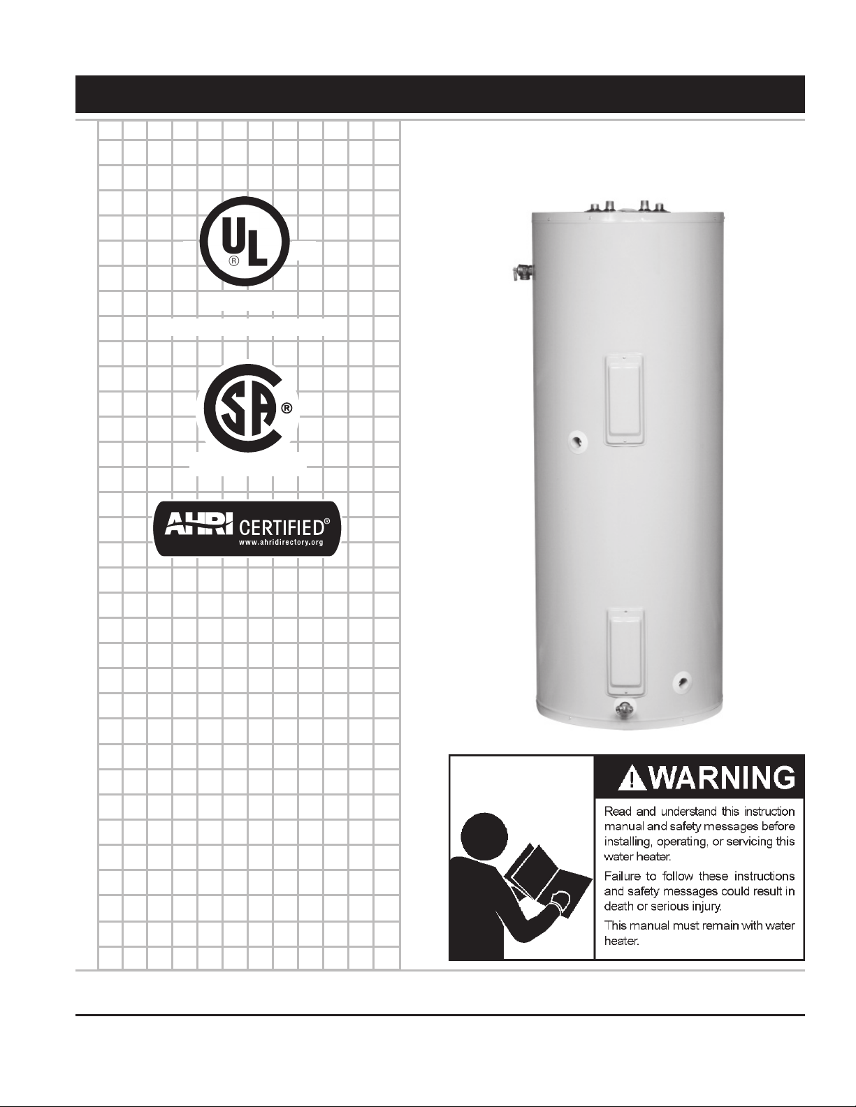
INSTALLATION - OPERATION - MAINTENANCE
Low Lead Content
C US
LISTED
Solar Water Heater
Instruction Manual
DIRECT SOLAR WATER HEATERS
FOR POTABLE WATER HEATING ONLY
ALL TECHNICAL AND WARRANTY QUESTIONS: SHOULD BE DIRECTED TO THE LOCAL DEALER FROM WHOM THE WATER HEATER WAS
PURCHASED. IF YOU ARE UNSUCCESSFUL, PLEASE WRITE TO THE COMPANY LISTED ON THE RATING PLATE ON THE WATER HEATER.
PRINTED 1215 184441-005
KEEP THIS MANUAL IN THE POCKET ON HEATER FOR FUTURE REFERENCE
WHENEVER MAINTENANCE ADJUSTMENT OR SERVICE IS REQUIRED.
1
1
Page 2
SAFE INSTALLATION, USE AND SERVICE
Your safety and the safety of others is extremely important in the installation, use, and servicing of this water heater.
Many safety-related messages and instructions have been provided in this manual and on your own water heater to
warn you and others of a potential injury hazard. Read and obey all safety messages and instructions throughout this
manual. It is very important that the meaning of each safety message is understood by you and others who install, use,
or service this water heater.
This is the safety alert symbol. It is used to alert
you to potential personal injury hazards. Obey all
safety messages that follow this symbol to avoid
possible injury or death.
DANGER
WARNING
CAUTION
CAUTION
All safety messages will generally tell you about the type of hazard, what can happen if you do not follow the safety
message, and how to avoid the risk of injury.
DANGER indicates an imminently hazardous situation
which, if not avoided, will result in death or injury.
WARNING indicates a potentially hazardous situation
which, if not avoided, could result in death or injury.
CAUTION indicates a potentially hazardous situation
which, if not avoided, could result in minor or moderate
injury.
CAUTION used without the safety alert symbol
indicates a potentially hazardous situation which, if
not avoided, could result in property damage.
IMPORTANT DEFINITIONS
• QualiedInstaller:A qualied installer must have ability equivalent to a licensed tradesman in the elds of plumbing and electrical
installation of these appliances. This would include a thorough understanding of the requirements of the National Electrical Code and
applicable local electrical and plumbing codes (and tools necessary to conrm proper installation and operation of the water heater) as
they relate to the installation of electric water heaters. The qualied installer must have a thorough understanding of the water heater
Instruction Manual.
• Service Agency: A service agency also must have ability equivalent to a licensed tradesman in the elds of plumbing and electrical
installation of these appliances. This would include a thorough understanding of the requirements of the National Electrical Code and
applicable local electrical and plumbing codes (and tools necessary to conrm proper installation and operation of the water heater) as
they relate to the installation of electric water heaters. The service agency must have a thorough understanding of the water heater
Instruction Manual.
2
Page 3
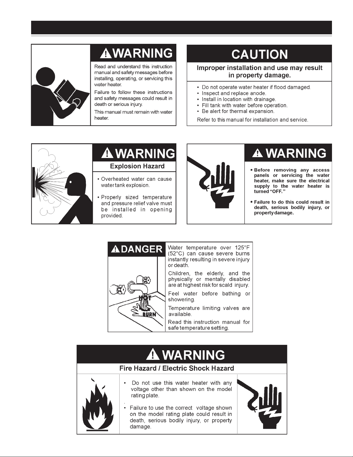
GENERAL SAFETY
3
3
Page 4

INTRODUCTION
Thank You for purchasing this solar water heater. Properly
installed and maintained, it should give you years of trouble
free service.
Abbreviations Found In This Instruction Manual:
• ANSI - American National Standards Institute
• ASME - American Society of Mechanical Engineers
• AHRI - Air-Conditioning, Heating, and Refrigeration Institute
• NEC - National Electrical Code
• NFPA - National Fire Protection Association
• UL - Underwriters Laboratories Inc.
• CSA - Canadian Standards Association
PREPARING FOR THE INSTALLATION
1. Read the “General Safety” section of this manual rst and then
the entire manual carefully. If you don’t follow the safety rules,
the solar water heater will not operate properly. It could cause
DEATH, SERIOUS BODILY INJURY, AND/OR PROPERTY
DAMAGE.
This manual contains instructions for the installation,
operation, and maintenance of the electric water heater. It also
contains warnings throughout the manual that you must read
and understand. All warnings and all instructions are essential
to the proper operation of the water heater and your safety.
READ THE ENTIRE MANUAL BEFORE ATTEMPTING TO
INSTALL OR OPERATE THE SOLAR WATER HEATER.
2. The installation must conform with these instructions and the
local code authority having jurisdiction and the requirements of
the power company. In the absence of local code requirements
follow NFPA-70, the National Electrical Code (current
edition), which may be ordered from: National Fire Protection
Association, 1 Batterymarch Park, Quincy, MA 02269.
3. If after reading this manual you have any questions or do not
understand any portion of the instructions, call the local utility
or the manufacturer whose name appears on the rating plate.
4. Carefully plan your intended placement of the water
heater. INSTALLATION OR SERVICE OF THIS WATER
HEATER REQUIRES ABILITY EQUIVALENT TO
THAT OF A LICENSED TRADESMAN IN THE FIELD
INVOLVED. PLUMBING AND ELECTRICAL WORK
ARE REQUIRED.
Examine the location to ensure the water heater complies with
the “Facts to Consider About the Location” section in this manual.
5. For California installation this water heater must be braced,
anchored, or strapped to avoid falling or moving during
an earthquake. See instructions for correct installation
procedures. Instructions may be obtained from California
Ofce of the State Architect, 400 P Street, Sacramento, CA
95814.
6. Massachusetts Code requires this water heater to be installed
in accordance with Massachusetts 248-CMR 2.00: State
Plumbing Code and 248-CMR 5.00.
TABLE OF CONTENTS
SAFE INSTALLATION, USE AND SERVICE............................2
GENERAL SAFETY..................................................................3
INTRODUCTION ...................................................................... 4
Preparing for the Installation...............................................4
TABLE OF CONTENTS ............................................................ 4
TYPICAL INSTALLATION ......................................................... 5
LOCATING THE NEW SOLAR WATER HEATER ....................6
Facts to Consider About the Installation .............................6
Insulation Blankets .............................................................6
INSTALLING THE NEW SOLAR WATER HEATER ............6-11
Local Codes........................................................................6
Temperature-Pressure Relief Valve .................................6-8
Closed System/Thermal Expansion ...................................8
Locating the Solar Water Heater ........................................8
Water Piping ..................................................................8-10
Filling the Solar Water Heater with Water .........................10
T&P Valve and Pipe Insulation (Selected Models) ........... 10
Wiring of Element ........................................................ 10-11
Thermostat ....................................................................... 11
Tank Sensor...................................................................... 11
OPERATION ........................................................................... 12
Temperature Regulation ................................................... 12
Temperature Settings .......................................................12
Temperature Adjustment...................................................12
FOR YOUR INFORMATION ...................................................13
Thermal Expansion...........................................................13
Strange Sounds ................................................................ 13
Water Odor .......................................................................13
“Air” in Hot Water Faucets ................................................13
High Temperature Shut Off System ..................................13
MAINTENANCE ................................................................14-15
Draining & Flushing .......................................................... 14
Element ............................................................................14
Heating Element Replacement ......................................... 14
Thermostat Removal / Replacement ................................ 14
Anode Rod Inspection ...................................................... 15
Temperature-Pressure Relief Valve Operation .................15
Water Heater Sounds .......................................................15
REPAIR PARTS ......................................................................16
Repair Parts Schedule......................................................16
4
Page 5
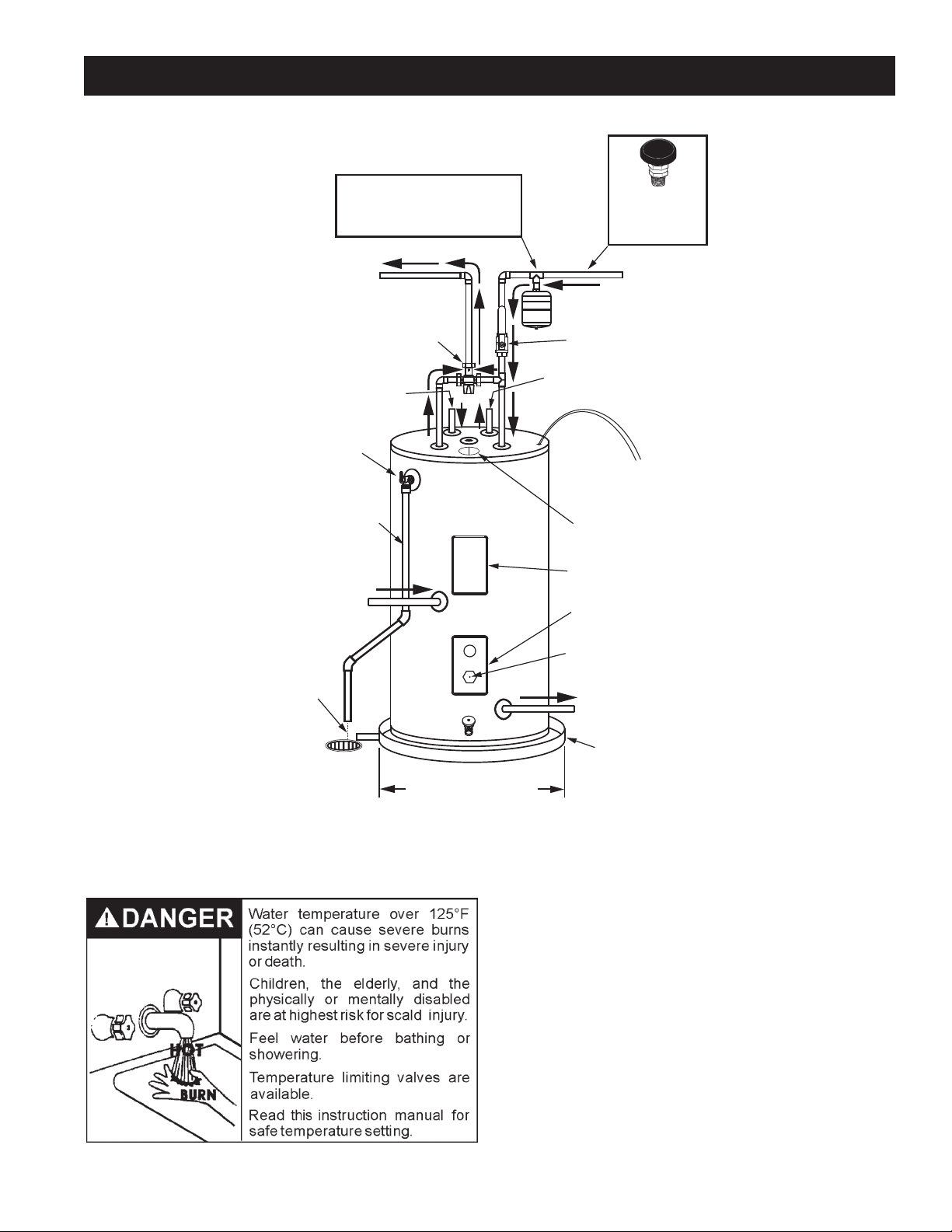
TYPICAL INSTALLATION
Check all connections for leaks. Consult the local utility company to examine installation for propriety and safety.
INSTALL THERMAL EXPANSION
TANK IF WATER HEATER IS
INSTALLED IN A CLOSED
TEMPERED
WATER
OUTLET
FROM
COLLECTOR
(SOLAR LOOP)
TEMPERATURE
PRESSURE
RELIEF VALVE
DISCHARGE PIPE
(DO NOT PLUG)
FROM
COLLECTOR
(SOLAR LOOP)
(ALTERNATE)
WATER SYSTEM
MIXING
VALV E
VACUUM RELIEF
VALV E
INSTALL PER
LOCAL CODES
COLD
WATER
INLET
WATER INLET
SHUTOFF
VALV E
TO PUMP
(SOLAR LOOP)
SENSOR
WIRES
ELECTRICAL
JUNCTION BOX
HEATING ELEMENT
ACCESS COVER
TANK SENSOR STUD
ACCESS COVER
6” AIR GAP
TO SUITABLE
DRAIN
DRAIN
VALV E
AT LEAST 2” GREATER
THAN THE DIAMETER
OF THE WATER HEATER.
Figure 1.
Water (Potable) Heating: All models are considered suitable
for water (potable) heating only.
TANK SENSOR STUD
TO PUMP
(SOLAR LOOP)
(ALTERNATE)
SUITABLE DRAIN PAN
HOTTER WATER CAN SCALD:
Water heaters are intended to produce hot water. Water heated to a
temperature which will satisfy space heating, clothes washing, dish
washing, and other sanitizing needs can scald and permanently injure
you upon contact. Some people are more likely to be permanently
injured by hot water than others. These include the elderly, children,
the inrm, or physically/mentally disabled. If anyone using hot water
in your home ts into one of these groups or if there is a local code
or state law requiring a certain temperature water at the hot water
tap, then you must take special precautions. In addition to using
the lowest possible temperature setting that satises your hot water
needs, a means such as a mixing valve should be used at the hot
water taps used by these people or at the water heater. Mixing valves
are available from your local plumbing contractor. Consult a Qualied
Installer or Service Agency. Follow mixing valve manufacturer’s
instructions for installation of the valves. Before changing the factory
setting on the thermostat, read the “Temperature Regulation” section
in this manual.
5
5
Page 6
LOCATING THE NEW SOLAR WATER HEATER
FACTS TO CONSIDER ABOUT THE LOCATION
Carefully choose an indoor location for the new solar water
heater, because the placement is a very important consideration
for the safety of the occupants in the building and for the most
economical use of the water heater.
Whether replacing an old water heater or putting the water
heater in a new location, the following critical points must
be observed:
1. Select a location indoors as close as practical or centralized
to the water piping system as possible. The solar water
heater should be located in an area not subject to freezing
temperatures.
2. Selected location must provide adequate clearances (4”/101.6
mm) for servicing parts such as the thermostats, drain valve, and
relief valve. Adequate clearance for servicing this water heater
should be considered before installation, such as changing the
anodes, etc.
3. The solar water heater should be located so it is not subject to
physical damage by moving vehicles or area ooding.
Installation of the solar water heater must be accomplished in
such a manner that if the tank or any connections should leak,
the ow will not cause damage to the structure. For this reason,
it is not advisable to install the solar water heater in an attic or
upper oor. When such locations cannot be avoided, a suitable
metal drain pan should be installed under the solar water heater.
Drain pans are available from your local plumbing contractor.
Such a drain pan must have a minimum length and width of at
least 2 inches (51 mm) greater that the water heater dimensions
and must be piped to an adequate drain.
Water heater life depends upon water quality, water pressure and the
environment in which the water heater is installed. Water heaters are
sometimes installed in locations where leakage may result in property
damage, even with the use of a drain pan piped to a drain. However,
unanticipated damage can be reduced or prevented by a leak detector
or water shut-off device used in conjunction with a piped drain pan.
These devices are available from some plumbing supply wholesalers
and retailers, and detect and react to leakage in various ways:
• Sensors mounted in the drain pan that trigger an alarm or turn off
the incoming water to the water heater when leakage is detected.
• Sensors mounted in the drain pan that turn off the water supply to
the entire home when water is detected in the drain pan.
• Water supply shut-off devices that activate based on the
water pressure differential between the cold water and hot
water pipes connected to the water heater.
INSULATION BLANKETS
Insulation blankets are available to the general public for external
use on electric water heaters but are not necessary with this
product. The purpose of an insulation blanket is to reduce the
standby heat loss encountered with storage tank heaters. Your
water heater meets or exceeds the National Appliance Energy
Conservation Act standards with respect to insulation and standby
loss requirements, making an insulation blanket unnecessary.
Should you choose to apply an insulation blanket to this heater,
you should follow these instructions below. Failure to follow these
instructions can result in re, serious personal injury, or death.
• Do not cover the temperature and pressure relief (T & P) valve
with an insulation blanket.
• Do not cover the instruction manual. Keep it on the side of the
water heater or nearby for future reference.
• Do obtain new warning and instruction labels for placement on
the blanket directly over the existing labels.
INSTALLING THE NEW SOLAR WATER HEATER
LOCAL CODES
The installation of solar water heater must be in accordance with
these instructions and all applicable local codes and electric utility
requirements. In the absence of local codes, install in accordance
with the current edition of the National Electrical Code (NFPA-70).
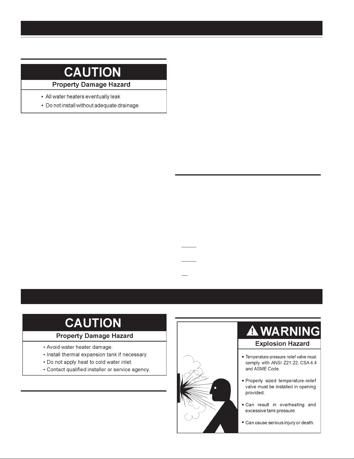
TEMPERATURE-PRESSURE RELIEF VALVE
6
Page 7

This heater is provided with a properly certied combination
temperature - pressure relief valve by the manufacturer.
The valve is certied by a nationally recognized testing laboratory
that maintains periodic inspection of production of listed equipment
of materials as meeting the requirements for Relief Valves for Hot
Water Supply Systems, ANSI Z21.22 • CSA 4.4, and the code
requirements of ASME.
7If replaced, the valve must meet the requirements of local codes,
but not less than a combination temperature and pressure relief
valve certied as indicated in the above paragraph.
The valve must be marked with a maximum set pressure
not to exceed the marked hydrostatic working pressure of
the water heater (150 psi = 1,034.21 kPa) and a discharge
capacity not less than the water heater input rate as shown
on the model rating plate (Electric heaters - watts x 3.412
equal BTU/hr rate).
For safe operation of the water heater, the relief valve must
not be removed from its designated opening nor plugged.
The temperature-pressure relief valve must be installed directly
into the tting of the water heater designed for the relief valve.
Position the valve downward and provide tubing so that any
discharge will exit only within 6 inches (152.4 mm) above an
adequate drain, or external to the building or structure. Be
certain that no contact is made with any live electrical part. The
discharge opening must not be blocked or reduced in size under
any circumstances. Excessive length, over 30 feet (9.14 m), or
use of more than four elbows can cause restriction and reduce
the discharge capacity of the valve.
No valve or other obstruction is to be placed between the relief
valve and the tank. Do not connect tubing directly to discharge
drain unless a 6 inch air gap is provided. The relief valve must
be allowed to discharge water in sufcient quantities, should
circumstances demand, to prevent bodily injury, hazard to life,
or property damage. If the discharge pipe is not connected
to a drain or other suitable means, the water ow may cause
property damage.
• Must not be capped, blocked, plugged or contain any valve
between the relief valve and the end of the discharge line.
• Must terminate a maximum of six inches above a oor drain
or external to the building. In cold climates, it is recommended
that the discharge line be terminated at an adequate drain
inside the building.
• Must be capable of withstanding 250°F (121°C) without
distortion.
• Must be installed to allow complete drainage of both the valve
and discharge line.
WATER INLET
SHUTOFF
VALV E
TEMPERATURE
PRESSURE
RELIEF VALV E
The Temperature & Pressure Relief Valve:
• Must not be in contact with any electrical part.
• Must be connected to an adequate discharge line.
• Must be rated higher than the working pressure shown on the
rating plate of the water heater
The Discharge Pipe:
• Must not be smaller than the pipe size of the relief valve or
have any reducing coupling installed in the discharge line.
6” AIR GAP
TO SUITABLE
7
7
DISCHARGE PIPE
(DO NOT PLUG)
DRAIN
DRAIN
VALV E
Figure 2.
Page 8

Figure 3.
WARNING: The temperature-pressure relief valve should be
manually opened once a year. Caution should be taken to ensure that
(1) no one is in front of or around the outlet of the temperaturepressure relief valve discharge line, and (2) the water manually
discharged will not cause any bodily injury or property damage
because the water may be extremely hot.
If after manually operating the valve, it fails to completely reset and
continues to release water, immediately close the cold water inlet
to the water heater, follow the draining instructions, and replace
the temperature-pressure relief valve with a new one.
WARNING: If the temperature-pressure relief valve on the water
heater weeps this may be due to thermal expansion. The water
supply serving this solar water heater may have a check valve
installed. Contact the water supplier or local plumbing contractor
on how to control this situation. Do not plug the temperaturepressure relief valve.
CLOSED SYSTEM/THERMAL EXPANSION
sized expansion tank in a closed system will void the warranty
on the water heater in the event of tank failure. It is important
to follow the thermal expansion tank manufacturers’ installation
instructions and to adjust the expansion tank pressure to match
the water supply pressure. Contact a plumbing service agency
or your retail supplier regarding the installation of a thermal
expansion tank.
LOCATING THE SOLAR WATER HEATER
If you have a choice of where to install the solar water heater,
these ideas may help you decide.
1. Put the solar water heater indoors as close as possible to where
you use the most hot water. This water heater is not
intended for outdoor installation.
2. It is handy to have a oor drain, tub or sink nearby. That will
make it easy to drain water from the water heater. It is also a
good place to end the drain line of the temperature-pressure
relief (T & P) valve.
3. The solar water heater or the pipes and the connections may,
in time, leak. Put the water heater in a place where a water
leak will not damage anything.
4. You must not put the water heater in an area where it might
freeze. You must turn off the electricity to the water heater
before you drain it, to protect the heating elements.
5. Make sure that you are able to reach the drain valve and all
access panels when the water heater is in place. This will make
it easy to service the water heater.
6. The water heater must be level before you begin the piping.
Most public water systems in North America are required to
prevent water owing from points of use (residences, businesses,
etc.) back into the supply system in order to maintain water quality.
To accomplish this, back ow preventers such as check valves,
are installed in the water line going to each point of use. Typically
the back ow preventer will be installed at the water meter or
inside a building where the supply line enters the building. This
device allows water to ow into the residence but does not allow
it to ow back into the water supply. This creates what is known
as a “Closed System”. As water is heated by the water heater,
the water in the system attempts to expand, but has nowhere to
go resulting in an increase in pressure. This increase in pressure
in the system may cause the temperature-pressure relief valve to
open to relieve the pressure. Water will drip from the temperature
and pressure relief valve. Premature tank failure will result if this
condition is not corrected. To prevent this condition, a properlysized thermal expansion tank should be installed in the cold
water supply to the water heater. Failure to install a properly
WATER HEATERS EVENTUALLY LEAK. The installation of the
water heater must be accomplished in such a manner that if the
tank or any connections should leak, the ow of water will not
cause damage to the area adjoining the water heater or to lower
oors of the structure. When such locations can’t be avoided, a
suitable drain pan should be installed under the water heater. Such
a pan should be no greater than 1-1/2 (45mm) inches deep, have
a minimum length and width of at least two inches (51mm) greater
than the water heater dimensions and must be piped to an
adequate drain.
WATER PIPING
8
Page 9

HOTTER WATER CAN SCALD:
Water heaters are intended to produce hot water. Water heated to
a temperature which will satisfy space heating, clothes washing,
dish washing, cleaning and other sanitizing needs can scald and
permanently injure you upon contact. Some people are more likely to
be permanently injured by hot water than others. These include the
elderly, children, the inrm, or physically/mentally disabled. If anyone
using hot water in your home ts into one of these groups or if there is
a local code or state law requiring a certain temperature water at the
hot water tap, then you must take special precautions. In addition to
using the lowest possible temperature setting that satises your hot
water needs, a means such as a mixing valve should be used at the
hot water taps used by these people or at the water heater. Valves
for reducing point of use temperature by mixing cold and hot water
are also available.
Consult a Qualified Installer or Service Agency. Follow
manufacturer’s instructions for installation of the valves.
Before changing the factory setting on the thermostat, read the
“Temperature Regulation” section in this manual.
This water heater shall not be connected to any heating systems
or component(s) used with a non-potable water heating appliance.
Use properly sized water heaters for spa or hot tub use.
Toxic chemicals, such as those used for boiler treatment shall not
be introduced into this system.
As water is heated, it expands (thermal expansion). In a closed
system, the volume of water will grow. As the volume of water
grows, there will be a corresponding increase in water pressure
due to thermal expansion. Thermal expansion can cause premature
tank failure (leakage). This type of failure is not covered under the
limited warranty. Thermal expansion can also cause intermittent
temperature-pressure relief valve operation: water discharged from
the valve due to excessive pressure build up. The temperaturepressure relief valve is not intended for the constant relief of thermal
expansion. This condition is not covered under the limited warranty
WARNING: Toxic chemicals such as used for treatment of boilers
or non-potable water heating appliances shall never be introduced
into a potable water space heating system.
Figure 4.
The solar water heater will work better if you keep the hot water
runs short. You will also get hot water faster and with less heat loss.
The illustration shows the correct valves and ttings that you
will need to install the solar water heater. Threaded (3/4”) water
connections are supplied through the tank top.
Figure 5.
A properly-sized thermal expansion tank should be installed on all
closed systems to control the harmful effects of thermal expansion.
Thermal expansion tanks are available through a local plumbing
contractor. Contact the local plumbing inspector, water supplier
and/or service agency for assistance in controlling these situations.
This water heater is design certied to be used with a potable
water system. When connecting water piping with solder joints
use only lead free solder.
WARNING: This solar water heater shall not be connected to any
heating systems or component(s) previously used with a nonpotable water heating appliance.
If this solar water heater is also used for space heating applications,
all piping and components connected to the solar water heater
shall be suitable for use with potable water.
This water heater has been design certied as a solar water heater
complying with Standards for Safety - UL 174/CAN/CSA C-22.2.
The particular application of this water heater described (above
paragraph) may be subject to review and approval by local code
ofcials.
1. Purchase the ttings that you need to connect the pipes.
Remember that you have to connect both the hot and cold
water pipes.
2. Apply a light covering of pipe joint compound to each outside
thread before making connection.
3. Connect the cold water supply pipe to the cold water inlet of
your solar water heater as follows:
a. Look at the top cover of the solar water heater. The hot
and cold connections are marked there.
b. A non-metallic dip tube is supplied to carry cold water from
the tank top to the bottom. Be sure that it is in the cold water
inlet.
c. If using copper tubing, solder tubing to an adapter
BEFORE you attach the adapter to the cold water inlet.
DO NOT solder the cold water supply pipe directly to
the cold water inlet connection. It might harm the dip tube.
d.
The cold water supply line must have a shut-off valve and union
4. Use a union to connect the hot water supply pipe to the solar
9
9
.
Page 10

water heater’s hot water outlet.
CAUTION: Operating an empty or partially lled solar water heater
will result in damage to the tank.
If a solar water heater is installed in a closed water system; such as
one having a back ow preventer, check valve or water meter with
check valve in the cold water supply line, means shall be provided
to control thermal expansion. Contact the water supplier or local
plumbing contractor on how to control this situation.
INSTALLATION IN RESIDENTIAL GARAGES: The solar water
heater must be located and/or protected so it is not subject to
physical damage by a moving vehicle.
FILLING THE SOLAR WATER HEATER WITH WATER
5. Never alter or modify the certied construction of the water
heater system or its components, or bypass any safety
features. Doing so voids all warranties.
T&P VALVE and PIPE INSULATION (Selected Models)
TEMPERED
WATER
OUTLET
FROM
COLLECTOR
(SOLAR LOOP)
FROM
COLLECTOR
(SOLAR LOOP)
(ALTERNATE)
DRAIN
VALV E
WATER INLET
SHUTOFF
VALV E
TO PUMP
(SOLAR LOOP)
TO PUMP
(SOLAR LOOP)
(ALTERNATE)
COLD
WATER
INLET
Remove insulation for T&P Valve and pipe connections from
carton.
Fit pipe insulation over the incoming cold water line and the hot
water line. Make sure that the insulation is against the top cover of
the heater.
Fit T&P Valve insulation over valve. Make sure that the insulation
does not interfere with the lever or outlet of the T&P valve.
Secure all insulation using tape.
Figure 6.
Before lling the solar water heater with water, the pump station
storage tank loop must be connected to the water heater.
The solar water heater is equipped with top and side pump station
water loop connections. Cap or plug the connections that are not
used in your application.
1. Close the solar water heater drain valve. The drain valve is on
the lower front of the solar water heater.
2. Open the cold water supply to the solar water heater. NOTE:
THIS VALVE MUST BE LEFT OPEN WHEN THE SOLAR
WATER HEATER IS IN USE.
3. Fill the solar water heater until a constant ow of water runs out
an opened hot water faucet. This will let out air in the solar
water heater and the piping. Close the faucet and solar loop
air vent after all air has been purged and the water comes out
with constant ow. You must not turn the electricity on until
the solar water heater is full of water. IF ANY AIR IS LEFT
IN THE TOP OF THE SOLAR WATER HEATER OR IN THE
PUMP STATION STORAGE TANK LOOP THE HEATING
ELEMENT WILL BURN OUT IMMEDIATELY.
4. Check all the new water piping for leaks. Fix as needed.
Figure 7.
WIRING OF ELEMENT
Never use water heater unless it is completely full of water. To
prevent damage to the tank and heating element, the tank must
be lled with water. Water must ow from the hot water faucet
before turning on power.
You must provide all wiring of the proper size outside of the
water heater. You must obey local codes and electric company
requirements when you install this wiring.
If you are not familiar with electric codes and practices, or if you
10
Page 11

have any doubt, even the slightest doubt, in your ability to connect
the wiring to this water heater, obtain the service of a competent
electrician. Contact a local electrical contractor and/or the local
electric utility.
WATER HEATERS EQUIPPED FOR ONE VOLTAGE ONLY: This
water heater is equipped for one type voltage only. Check the
rating plate near the bottom access panel for the correct voltage.
DO NOT use this water heater with any voltage other than the
one shown on the model rating plate. Failure to use the correct
voltage can cause problems which can result in DEATH, SERIOUS
BODILY INJURY, OR PROPERTY DAMAGE. If you have any
questions or doubts consult your electric company.
If wiring from your fuse box or circuit breaker box was aluminum
for your old water heater, replace it with copper wire. If you wish
to reuse the existing aluminum wire, have the connection at the
water heater made by a competent electrician. Contact a local
electrical contractor and/or the local electric utility.
1. Provide a way to easily shut off the electric power when working
on the water heater. This could be with a circuit breaker or
fuse block in the entrance box or a separate disconnect switch.
2. Install and connect a circuit directly from the main fuse or circuit
breaker box. This circuit must be the right size and have its
own fuse or circuit breaker.
3. If metal conduit is used for the grounding conductor:
A. The grounding electrode conductor shall be of copper,
aluminum, or copperclad aluminum. The material shall be of
one continuous length without a splice or joint.
B. Rigid metal conduit, intermediate metal conduit, or electrical,
metallic tubing may be used for the grounding means if conduit
or tubing is terminated in ttings approved for grounding.
C. Flexible metal conduit or exible metallic tubing shall
be permitted for grounding if all the following conditions
are met:
• The length in any ground return path does not exceed 6 feet
(1.8 m).
• The circuit conductors contained therein are protected by
overcurrent devices rated at 20 amperes or less.
• The conduit or tubing is terminated in ttings approved
for grounding.
• For complete grounding details and all allowable
exceptions, refer to the current edition of the Nation
Electrical Code NFPA 70.
4. A standard 1/2” (1.27 cm) conduit opening has been made in
the water heater junction box for the conduit connections.
5. Use wire nuts and connect the power supply wiring to the wires
inside the water heater’s junction box.
6. The water heater must be electrically “grounded” by the installer.
A green ground screw has been provided on the water heater’s
junction box. Connect ground wire to this location.
7. Replace the wiring junction cover using the screw provided.
Figure 8.
CAUTION: If wiring from the fuse box or circuit breaker box was
aluminum for the old tank, replace it with copper wire. If you wish
to reuse the existing aluminum wire, have the connection at the
solar water heater made by a competent electrician. Contact your
local utility to arrange for a professional electrician.
BLACK
RED
F
C)(49
F
(60 C)
F
C)(66
BLACK
RED
ELEMENT
Figure 9.
THERMOSTAT
Each thermostat is factory preset at 120°F (49°C) to reduce the
risk of scald injury. This setting has proven by experience to be
most satisfactory from the standpoint of operational costs and
household needs.
Solar water heaters installed in Florida require the thermostat(s)
to be set at 125°F (52°C). If you wish to adjust the settings, see
the “Temperature Adjustment” section of this installation manual.
TANK SENSOR
The surface mount tank sensor should be attached to the sensor
stud behind the lower door by placing the hole in the sensor over
the stud provided and securing in place with a nut. The end of the
tank sensor shall be connected to the red wires in the opening with
wire nuts (with no regard for polarity). The other ends of the red
temperature sensor extension extend from the top of the tank and
shall be connected to the controller in the tank sensor position.
11
11
Page 12

THERMOSTAT
HIGH LIMIT
OPERATION
TEMPERATURE REGULATION
HOTTER WATER CAN SCALD: Solar water heaters are intended
to produce hot water. Water heated to a temperature which will
satisfy clothes washing, dish washing, and other sanitizing needs
can cause scalds resulting in serious personal injury and/or death.
Some people are more likely to be permanently injured by hot water
than others. These include the elderly, children, the inrmed, or
physically handicapped. If anyone using hot water in your home
ts into one of these groups or if there is a local code or state
law requiring a certain temperature water at the hot water tap,
then you must take special precautions. In addition to using the
lowest possible temperature setting that satises your hot water
needs, some type of tempering device, such as a mixing valve
should be used at the hot water taps used by these people or at
the solar water heater. Mixing valves are available at plumbing
supply or hardware stores. Follow manufacturers instructions for
installation of the valves. Before changing the factory setting of
the thermostat, read the Temperature Adjustment section.
KEEPING THE THERMOSTAT SETTING AT 120°F (49°C) WILL
REDUCE THE RISK OF SCALDS. Never allow small children to
use a hot water tap, or to draw their own bath water. Never leave
a child or handicapped person unattended in a bathtub or shower.
TEMPERATURE SETTINGS
NOTE: Residential solar water heaters will not supply sanitizing
hot water for dishwashers.
The thermostat is factory set at its lowest position which
approximates 120°F (49°C) (Hot) and is adjustable if a different
water temperature is desired. Read all warnings in this manual
and on the solar water heater before proceeding.
CONTROL
RESET
BUTTON
ADJUSTABLE
WITH
HIGH LIMIT
Water
Temperature
°F(°C)
110 (43)
116 (47)
116 (47)
122 (50)
131 (55)
140 (60)
149 (65)
154 (68)
(U.S. Government Memorandum, C.P.S.C., Peter L. Armstrong, 9/15/1978)
Time for 1st Degree
Burn
(Less Severe Burns)
(normal shower temp.)
(pain threshold)
35 minutes
1 minute
5 seconds
2 seconds
1 second
Instantaneous
Time for Perma-
nent Burns 2nd &
3rd Degree (Most
Severe Burns)
45 minutes
5 minutes
25 seconds
5 seconds
2 seconds
1 seconds
Figure 10.
TEMPERATURE ADJUSTMENT
To adjust the temperature setting:
1. Turn off the heater electrical supply. Do not attempt to adjust
thermostat with power on.
2. Remove the thermostat access panel(s) and fold up insulation
to expose the thermostats. Do not remove the plastic personnel
protectors covering the thermostats.
3. Using a at tip screwdriver, rotate the adjustment knob to the
desired temperature setting.
4. Replace the insulation and access panels and turn on heater
electrical supply.
A non-adjustable high temperature limit control operates before
steam temperatures are reached. The high limit is in the same
area as the upper thermostat and must be reset manually when it
operates. BECAUSE THE HIGH LIMIT OPERATES ONLY WHEN
ABNORMALLY HIGH WATER TEMPERATURES ARE PRESENT,
IT IS IMPORTANT THAT A QUALIFIED SERVICE AGENT BE
CONTACTED TO DETERMINE THE REASON FOR OPERATION
BEFORE RESETTING.
12
Page 13

FOR YOUR INFORMATION
THERMAL EXPANSION
As water is heated, it expands (thermal expansion). In a closed
system, the volume of water will grow. As the volume of water
grows, there will be a corresponding increase in water pressure
due to thermal expansion. Thermal expansion can cause premature
tank failure (leakage). This type of failure is not covered under the
limited warranty. Thermal expansion can also cause intermittent
temperature-pressure relief valve operation: water discharged from
the valve due to excessive pressure build up. The temperaturepressure relief valve is not intended for the constant relief of thermal
expansion. This condition is not covered under the limited warranty
A properly-sized thermal expansion tank should be installed on all
closed systems to control the harmful effects of thermal expansion.
Thermal expansion tanks are available through a local plumbing
contractor. Contact the local plumbing inspector, water supplier
and/or service agency for assistance in controlling these situations.
STRANGE SOUNDS
Possible noises due to expansion and contraction of some metal
parts during periods of heat-up and cool-down do not necessarily
represent harmful or dangerous conditions.
WATER ODOR
In each water heater there is installed at least one anode rod (see
parts sections) for corrosion protection of the tank. Certain water
conditions will cause a reaction between this rod and the water.
The most common complaint associated with the anode rod is one
of a “rotten egg smell” in the hot water. This odor is derived from
hydrogen sulde gas dissolved in the water. The smell is the result
of four factors which must all be present for the odor to develop:
“AIR” IN HOT WATER FAUCETS
HYDROGEN GAS: Hydrogen gas can be produced in a hot
water system that has not been used for a long period of time
(generally two weeks or more). Hydrogen gas is extremely
ammable and explosive. To prevent the possibility of injury
under these conditions, we recommend the hot water faucet,
located farthest away, be opened for several minutes before any
electrical appliances which are connected to the hot water system
are used (such as a dishwasher or washing machine). If hydrogen
gas is present, there will probably be an unusual sound similar to
air escaping through the pipe as the hot water faucet is opened.
There must be no smoking or open ame near the faucet at the
time it is open.
HIGH WATER TEMPERATURE SHUT OFF SYSTEM
A non-adjustable high temperature limit control operates
before steam temperatures are reached. The high limit is
in the same area as the upper thermostat and must be
reset manually when it operates. BECAUSE THE HIGH LIMIT
OPERATES ONLY WHEN ABNORMALLY HIGH WATER
TEMPERATURES ARE PRESENT, IT IS IMPORTANT THAT A
QUALIFIED SERVICE AGENT BE CONTACTED TO DETERMINE
THE REASON FOR OPERATION BEFORE RESETTING.
A. A concentration of sulfate in the supply water.
B. Little or no dissolved oxygen in the water.
C. A sulfate reducing bacteria which has accumulated within the
water heater (this harmless bacteria is nontoxic to humans).
D. An excess of active hydrogen in the tank. This is caused by
the corrosion protective action of the anode.
Smelly water may be eliminated or reduced in some water heater
models by replacing the anode(s) with one of less active material,
and then chlorinating the water heater tank and all hot water lines.
Contact the local water heater supplier or service agency for
further information concerning an Anode Replacement Kit and this
chlorination treatment. If the smelly water persists after the anode
replacement and chlorination treatment, we can only suggest that
chlorination or aeration of the water supply be considered to eliminate
the water problem.
Do not remove the anode leaving the tank unprotected. By
doing so, all warranty on the water heater tank is voided.
• Turn off the heater electrical supply. Do not attempt to reset
thermostat with power on.
• Remove the screw securing the outer door and remove door.
• Fold up the insulation to expose the reset button.
• Reset the high limit by pushing in the red button marked
“RESET”.
13
13
Page 14

MAINTENANCE
DRAINING & FLUSHING
and wattage rating by matching it to the rating plate on the water
heater. Position the new gasket(s) on the element and insert
it into the water heater tank (Figure 12). Tighten the element
by turning it clockwise until secure.
7. Close the drain valve. Open the nearest hot water faucet and
allow the tank to ll completely with water. To purge the lines
of any excess air and sediment, keep the hot water faucet
The water heater should be drained if being shut down during
freezing temperatures. It is recommended that the tank be drained,
and ushed every 6 months to remove sediment which may buildup
during operation. To drain the tank perform the following steps:
1. Disconnect the electrical power to the water heater.
2. Open a hot water faucet until water is no longer hot.
3. Close the cold water inlet valve and open a hot water faucet.
4. Connect a hose to the drain valve and terminate it to an
adequate drain.
5. Open the water heater drain valve and the nearest hot water
faucet. Allow all the water to drain from the tank. Flush the tank
with water as needed to remove sediment.
6. Close the drain valve and completely rell the water heater tank.
7. Reconnect electrical power to the water heater. If the water
heater is going to be shut down for an extended period, the
drain valve should be left open.
open for 3 minutes after a constant ow of water is obtained.
8. Check for leaks around the element(s).
9. Reconnect the electrical wires to the element and securely
tighten the screws. Replace the plastic thermostat cover
making sure the attachment points are engaged on the
thermostat.
10. Replace the access cover(s).
11. Make certain the tank is lled with water. Applying electric
current to heater elements not submerged in water will destroy
them.
12. Reconnect electrical power to the water heater.
THERMOSTAT REMOVAL / REPLACEMENT
Figure 12
SCREW-IN
ELEMENT
SPUD
GASKET
ELEMENT
In some water areas, scale or mineral deposits will build up on
heating elements. This build up will cause a rumbling noise.
Follow the element replacement directions to remove the elements
from the tank. Soaking in vinegar and scraping will remove the
mineral deposit. Be careful not to bend the element.
HEATING ELEMENT REPLACEMENT
Replacement heating elements must be of the same style and
voltage/wattage rating as the ones presently in the water heater.
This information can be found on the ange or terminal block of
the element or on the water heater data plate.
1. Disconnect the electrical power to the water heater.
2. Drain water heater as directed in “Draining and Flushing” section.
3. Remove the access cover(s). Fold up the insulation from the
heater element(s). Remove the plastic thermostat cover from
the thermostat(s) making sure to disengage the attachment
point from the thermostat.
4. Disconnect the electrical wires from the heating element(s)
by loosening the screws (Figure 11). Remove the screw-in
element(s) by turning the element(s) counterclockwise with
a 1-1/2 inch socket wrench. Remove the existing gasket(s).
WIRES
ELEMENT
1. Turn “OFF” the electric power supply to the water heater.
2. Remove the outer door. Remove or fold up the insulation pad.
3. Models with Upper or Lower Thermostat with High Limit:
Lift out the tab as shown below to unclip the terminal cover
from the thermostat. The terminal cover can now be removed
from the thermostat.
SCREWS
Figure 11
5. Clean the area where the gasket(s) ts to the tank. If you
are replacing the bottom element, remove the accumulated
sediment on the bottom of the tank.
6. Make sure the replacement element(s) has the correct voltage
Figure 13
4. Disconnect wires from thermostat and slide out of the bracket.
5. Remove the thermostat from behind the thermostat bracket.
6. Place the new lower thermostat in the bracket making sure it
ts rmly against the tank.
14
Page 15

7. Attach the wires to the new thermostat.
NOTE: Some of the terminals may require straight-in wiring
through an eye-opening. If wires are now looped, recut and
strip wire 3/8” (9.525 mm) to a straight length and insert.
8. Put plastic terminal cover back in place.
9. Replace the insulation to cover the thermostat.
10. Replace outer door then turn the electric power on.
ANODE ROD INSPECTION
TEMPERATURE-PRESSURE RELIEF VALVE OPERATION
Each water heater contains at least one anode rod, which will
slowly deplete (due to electrolysis) prolonging the life of the water
heater by protecting the glass-lined tank from corrosion. Adverse
water quality, hotter water temperatures, high hot water usage,
and water softening methods can increase the rate of anode rod
depletion. Once the anode rod is depleted, the tank will start to
corrode, eventually developing a leak.
Certain water conditions will cause a reaction between the anode
rod and the water. The most common complaint associated with the
anode rod is a “rotten egg smell” produced from the presence of
hydrogen sulde gas dissolved in the water. IMPORTANT: Do not
remove this rod permanently as it will void any warranties. A special
anode rod may be available if water odor or discoloration occurs.
NOTE: This rod may reduce but not eliminate water odor problems.
The water supply system may require special ltration equipment
from a water conditioning company to successfully eliminate all
water odor problems.
Articially softened water is exceedingly corrosive because the
process substitutes sodium ions for magnesium and calcium ions.
The use of a water softener may decrease the life of the water
heater tank.
The anode rod should be removed from the water heater tank
every 3 years for inspection. NOTE: articially softened water
requires the anode rod to be inspected annually.
The following are typical (but not all) signs of a depleted anode rod:
• The majority of the rods diameter is less than 3/8” (9.5mm).
• Signicant sections of the support wire (approx. 1/3 or more
of the anode rod’s length) are visible.
If the anode rod show signs of either or both it should be replaced.
NOTE: Whether re-installing or replacing the anode rod, check for
any leaks and immediately correct if found.
In replacing the anode:
1. Turn off power to the water heater.
2. Shut off the water supply and open a
EXPOSED
SUPPORT
WIRE
nearby hot water faucet to depressurize
the water tank.
3. Drain approximately 5 gallons (19 L)
of water from tank. (Refer to “Draining
and Flushing” for proper procedures).
Close drain valve.
PITTED
ANODE
ROD
4. Remove old anode rod.
5. Use Teflon® tape or approved pipe
sealant on threads and install new
anode rod.
6. Turn on water supply and open a
nearby hot water faucet to purge air
from water system. Check for any
leaks and immediately correct any
if found.
7. Restart the water heater as directed
EXPOSED
SUPPORT
WIRE
Figure 14.
The temperature-pressure relief valve must be manually operated
at least once a year.
When checking the temperature-pressure relief valve operation,
make sure that (1) no one is in front of or around the outlet of the
temperature-pressure relief valve discharge line, and (2) that the
water discharge will not cause any property damage, as the water
may be extremely hot, see Figure 16.
If after manually operating the valve, it fails to completely reset and
continues to release water, immediately close the cold water inlet
to the water heater, follow the draining instructions, and replace
the temperature-pressure relief valve with a new one.
If the temperature-pressure relief valve on the water heater weeps
or discharges periodically, this may be due to thermal expansion.
You may have a check valve installed in the water line or a water
meter with a check valve. Consult your local water supplier or
service agency for further information. Do not plug or remove the
temperature-pressure relief valve.
WATER HEATER SOUNDS
1. The solar water heater is equipped with an immersion
heating element for fastest recovery. If the solar water
heater occasionally makes noises this is not a defect or a
safety hazard.
2. Lime or scale has accumulated on the heating element
causing a hissing sound. Element scale removal can be
accomplished by using vinegar or by scraping.
15
15
in this manual. See the Repair Parts Illustration for anode
rod location.
Figure 15.
Figure 16.
Page 16

REPAIR PARTS
REPAIR PARTS SCHEDULE
ORDERING REPAIR PARTS
The following parts may be ordered through the store you purchased the solar water heater from, or direct from the factory listed on
the model & rating plate located on the lower front of the solar water heater. Selling prices will be furnished on request or parts will
be shipped at prevailing prices and you will be billed accordingly. When ordering repair parts always give the following information:
(1) Part description, (2) Model serial number, (3) Element wattage, (4) Voltage, (5) Part number.
ITEM PART DESCRIPTION
1 Primary Anode 9003892005
2 Anode Outlet 9006827005
3 Primary Dip Tube 9002549005
4 Element w/Gasket 9003950115
5 Thermostat Bracket 9003898215
6 Thermostat w/High Limit 9007623015
7 Terminal Cover 9003914015
Access Panel
8
9 Sensor Mounting Plug 9007309005
10 Solar Loop Dip Tube (From Collector) 9006789005
11 Solar Loop Dip Tube w/Nipple (To Pump) 9006790005
12 Plastisert Nipple 9003976015
13 T&P Valve 9000728015
14 Drain Valve 9003906015
SERVICE
PART #
9003900005
RATING PLATE
A rating plate identifying the solar water heater will be found above the drain valve. When referring to the solar water heater, always
have the information listed on the rating plate readily available.
Fill in that information here:
MODEL NO. _______________________________________
SERIAL NO. _______________________________________
INSTALLATION DATE: _______________________________
16
Page 17

NOTES
17
17
Page 18

NOTES
18
Page 19

NOTES
19
19
Page 20

20
 Loading...