

Page 1
Wat er H ea te r
^Sm il h
Innovation has a name.
EWS
6,10,15, 25
®Smith
Utres
f
Use r Ma nu al
\
- - - - - - ml (23%) III
■ ^stronger/ '
i'
Page 2
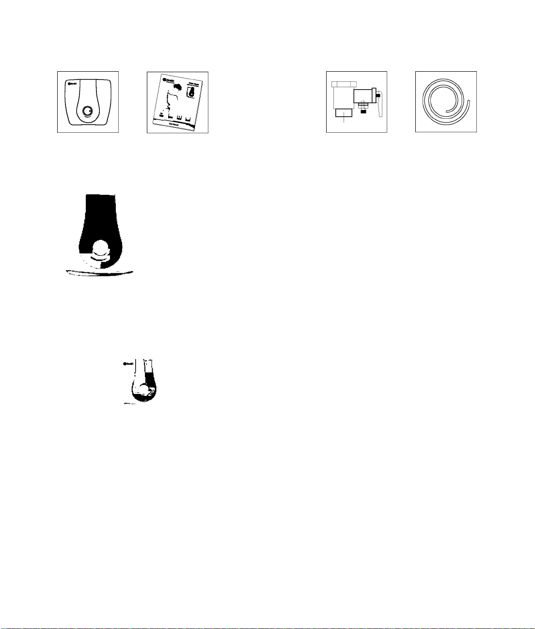
What's in the box?
Electric
Water Heater
User
Manual
Wall Mounting
Accessory
Safety Valve
Drain Pipe
A.O. Smith ColourMatch System Optional
®Smlth
The A.O. Smith ColourMatch System™ allows your water heater to match the colours of your home.
Call the A.O. Smith Customer Care Centre [1.800.103.2468] to order one of the decorative front panel
colour options and we will have it delivered free of charge.
o
White Blue
Ivory
Red Brick Olive
O
è
Steel Grey Lavender
•»nw •anw I \
■
Brown
Page 3

Contents
Specifications 2
Key Features 3
Glass Coated Element
Blue Diamond Glass Lining
Anode Rod Protection
Safety Valve
Thermal Cutout
Installation................................................................4
Mounting
Plumbing
Electrical Connections
Water Filling
Operation Instructions 5
Maintenance and Cleaning 6
Changing the Decorative Front Panel
...................
Troubleshooting 7
Circuit Diagram........................................................7
Warranty...................................................................8
6
Page 4
Specifications
Model EWS-6 EWS-10 EWS-15 EWS-25
Capacity [Itrs.] 6 10 15 25
◄
Power Supply
Wattage [kW] 2 2 2 2
--------------
---------
230V/50Hz
--------------
---------------
►
Max Stdg. Loss [kWh/24h/45°C diff.]
[as per ISI 2082:1993 amended in 2002]
Actual Stdg. Loss [kWh/24h/45°C diff.] 0.51 0.62 0.75 0.924
Reheating Time for 50°C rise [in min] 16 33 48 72
0.792
0.99 1.138 1.386
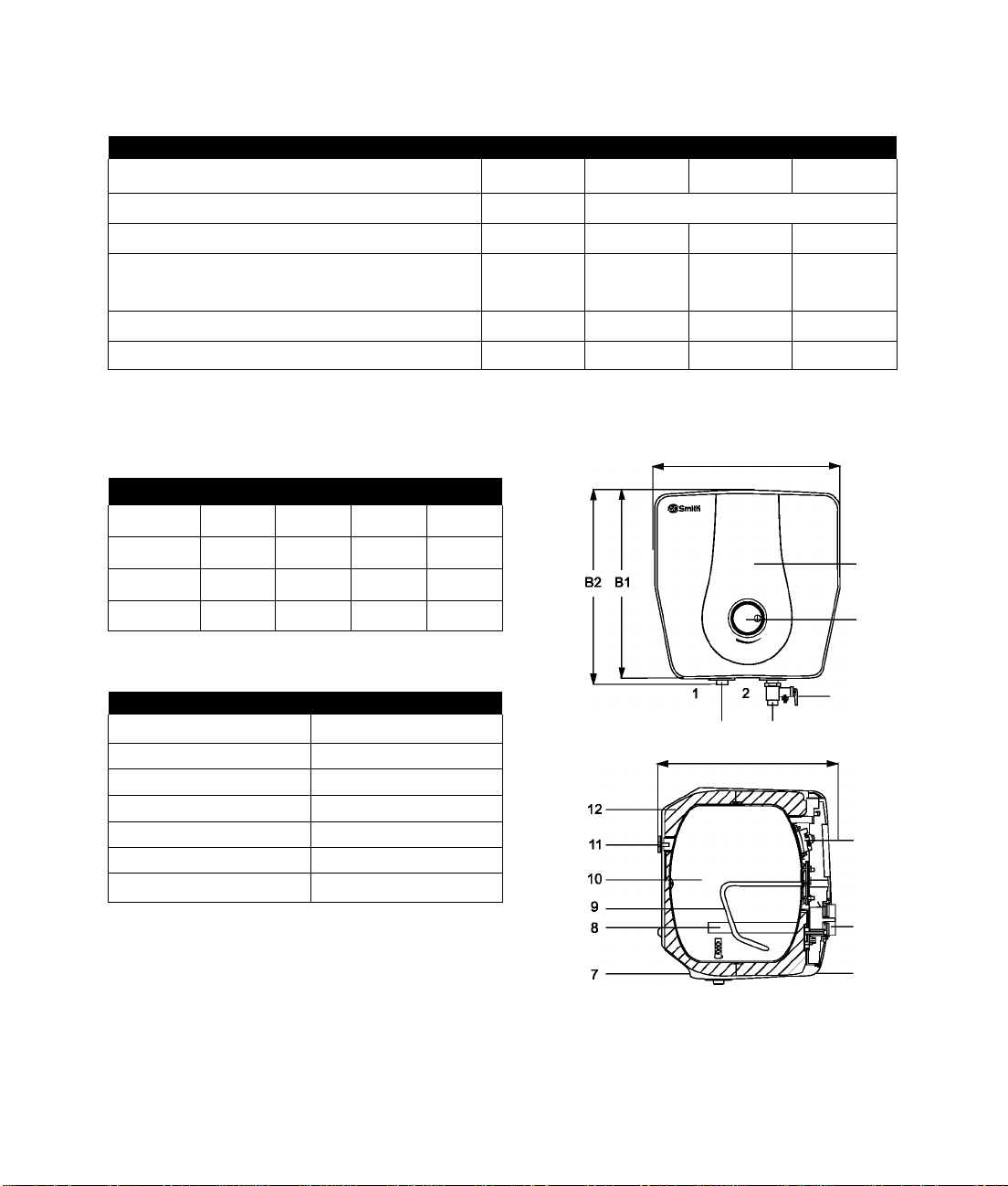
Dimensions and Parts
Model EWS-6 EWS-10 EWS-15 EWS-25
A [mm] 317 373 373 444
B1 [mm] 317 373 373 444
B2 [mm] 326 380 382 453
C [mm] 258 277 348 383
Part Descriptors
1 Outlet 8 Anode
2 Inlet 9 Pleating Element
3 Safety Val ve
4 Thermostat Knob 11 Installation Bracket
5 Decorative Front Panel 12 PU Insulation
6 Front Jacket 13 Thermal Cutout
7 BackJacket
10 Tank
13
Page 5

Key Features
Glass Coated Element reduces electricity bills and increases the life of the heating element
Scale and sediment build up on the surface of standard elements leading to higher
electricity bills and premature failure. An A. O. Smith Glass Coated Element helps to
prevent scale formation on the element reducing your electricity bill and extending
the life of the element.
Blue Diamond Glass Lining offers the best protection against tank corrosion
The new Blue Diamond technology with enhanced levels of zircon increases the life of
the water heater. The lining is proven to be stronger and more water-resistant than
any other in the industry.
Anode Rod protects the tank from corrosion
The tank has an anode rod system with a stainless-core that is designed to protect the
tank from corrosive elements. The system uses a special cathodic action to fight the
corrosive elements which in turn prolongs the life of the water heater.
Safety Valve discharges water in case pressure or temperature exceeds preset limits
This water heater has a temperature and pressure safety valve. This valve is designed
to automatically relieve and discharge water incase the pressure or temperature
overshoots the preset limits.
Thermal Cutout cuts off live line and zero line, in case of fault, ensuring safety
The breaker rapidly cuts off live line and zero line simultaneously to guarantee safety,
in case the water heater happens to be faulty and water temperature exceeds the
highest temperature preset in the thermostat.
Page 6

Installation
Mounting
1 Make sure that the wall can withstand at least twice the weight of water heater when completely filled
with water.
2 Before locating the position for installation, make sure that there is a clearance of no less than 300
mm between the front of the heater and the wall. This allows easy opening of the decorative front
panel for maintenance or to reset the thermal cutout when necessary.
3 Use a drill bit with diameter of 10mm to drill 4 holes at least 90mm deep in the wall. The four holes
should be aligned horizontally and vertically. The horizontal distance between the 2 holes should be
120mm and the vertical distance should be 57mm as shown in the above diagram.
4 Insert the expansion anchors into the holes. Place the wall bracket over the expansion anchors and
screw the four screws tight against the bracket.
5 Hang the water heater using the hanger hooks on the wall, through the 4 holes on its mounting
bracket. Move the water heater downward to ensure that the holes are pressed against the root of the
hanger hooks and ensure the water heater is fixed steadily.
Plumbing
1 Make necessary plumbing with reference to the installation diagram on the right page.
2 Connect the safety valve in the water inlet [blue]. It must be installed at the side of the inlet pipe. It
has been factory set at 0.8 MPa and is not adjustable. The discharge tube of this valve must face
downward and the discharged water must be piped up to or within 15cm above a suitable drain.
Under any circumstances, the drain line cannot be blocked and must be open to atmosphere.
Attention: The direction of arrow points to the water heater that indicates the direction of the water
flow current.
3 Connect the hot water pipe to the outlet [red].
Attention: Make sure a suitable sealing tape is used for all connections to prevent leakage. Meanwhile,
the safety valve must not be screwed too tight to prevent damage.
Page 7

Electrical Connections
The power cord and plug are connected with this water heater. Find a separate socket for power plug and
make sure the socket is in contact with the plug.
Filling Water
1 Open a hot water faucet nearby to permit the air
to escape.
2 Open the cold-water inlet valve fully, filling the
heater and the piping.
3 Close the hot-water faucet when water flows.
4 Check all the connections to see if there is any
leak. In case of a leak, drain the heater
completely, repair the leaking joint and then refill
the heater.
Operation Instructions
1 Switch on the water heater's power supply. The
yellow indicator light comes on.
2 Turn the thermostat knob clockwise for the device
to commence heating and change the set
temperature. A red light will come on. The set
temperature increases if the thermostat knob is
turned clockwise. Temperature can be set in the
range of 25°C to 75°C.
3 The red light's switching off indicates the heater
has been heated to the set temperature.
Page 8

Maintenance and Cleaning
Check proper functioning of the safety valve every two months by opening and closing the test lever. The
heating element should be checked annually for scale formation, caused by impurities in the water supply.
Also, the anode should be checked annually and replaced when worn out over 60%. For cleaning the
element or replacing the anode use the following procedure:
1 Switch off the electric supply to the water heater.
2
Open the hot water taps until the water is not hot any more.
3
Close cold water supply.
4
Drain the water heater by removing the safety valve in the direction
of the arrow as indicated in the diagram shown along side and open the hot water taps.
5
Take off the water heater from the hanger hook, when the water heater is empty.
6
Remove the decorative front panel, unscrew the heating assembly flange.
7
Clean the container and the heating element assembly from scale by using a suitable acid or by gently
scraping the scale.
8 Replace anode if required.
9 Remount the heating assembly flange.
10 Hang the water heater on the hanger hook on the wall through the 2 holes of its mounting bracket.
Move the water heater downward to ensure that the holes are pressed against the root of the hanger
hooks and ensure the water heater is fixed steadily.
11 Open cold water supply until water flows without interruption from hot water faucets.
12 Close the hot water taps and check for eventual leakage around the flange.
13 When there is no leakage, replace the decorative front panel. Then switch on electric supply.
Changing the Decorative Front Panel
Pull out the Knob Unscrew Remove the Decorative Front
panel to change
Panel
Page 9

Troubleshooting
Problem Cause(s) Action
Yellow and Red light
off
No hot water
Yellow light on Red
light off
No hot water
Water temperature is
too high
Water heats slowly Non-functioning element Element to be replaced
Thermostat does not
shut off
Piping connection leaks Connection not sealed Re-connect piping, using sealing tape
Leaky cover Tank or parts leak
No power to heater
Thermal cutout switch open
Control circuit or internal
wiring error
Non-functioning
thermostat
Control circuit or internal
wiring error
Thermostat set is too high Thermostat to be replaced
Thermal cutout trips Call Customer Care Center on 1.800.103.2468
Non-functioning
thermostat
Improper calibration Thermostat to be replaced
Turn on electrical switch. Check for
blown fuses or tripped breaker
Reset. Check for source of trouble and correct
Call Customer Care Center on 1.800.103.2468
Call Customer Care Center on 1.800.103.2468
Call Customer Care Center on 1.800.103.2468
Call Customer Care Center on 1.800.103.2468
Thermostat to be replaced
Call Customer Care Center on 1.800.103.2468
Call Customer Care Center on 1.800.103.2468
Shut off power immediately and
Call Customer Care Center on 1.800.103.2468
Circuit Diagram
High limit
Page 10

Warranty
1 Shall any part or component other than the tank and the heating
element be proved defective in material or workmanship within
two years after initial installation date, upon examination by
A. O. Smith or local authorized agent, A. O. Smith will repair or
supply such part or component through the local agent.
2 Shall the tank fail due to rust, corrosion or leakage, within seven
years of initial installation; A. 0. Smith will replace the tank free of
cost.
3 The warranty only applies if:
a. The water heater has been installed as per these instructions.
b. Maintenance has been carried out as instructed.
c. Safety valves and anodes have been kept in right working
condition.
4 The warranty is void if:
a. The tank has been damaged by external causes.
b. In case of misuse, neglect or incorrect use of the water heater.
c. In case of any unauthorized alteration, modification or repair.
5 The tank carries a warranty for 7 years and the heating element
for 4 years [2 + 2 years]. 2 years additional warranty on heating
element after registration within two months of purchase. The rest
of the parts carry a warranty of 2 years.
■years
Extended'
Warranty
Register your product with the
A. O. Smith Customer Care
Centre [1.800.103.2468] within
two months of purchase. You will
get an extended warranty on the
element [from 2 years to 4 years].
You can also get an additional
changeable Decorative Front
Panel in a color of your choice,
without cost.
Page 11

фЗгпиН
Innovation has a name.
T: 1.800.103.2468 www.aosmithindia.com
 Loading...