

A.O.Smith ESTT-40 OWNERS MANUAL
RESIDENTIAL ELECTRIC WATER HEATER
OWNER'S MANUAL
Thank you for buying this water heater from A.O. Smith Water Products
Company. We appreciate your confidence in our products.
Please read through this informative manual and pay special attention to
the following:
GENERAL SAFETY INFORMATION
CAUTION
TEXT PRINTED OR OUTLINED IN RED CONTAINS INFORMATION RELATIVE
TO YOUR SAFETY.
AND USING THIS APPLIANCE.
Do not operate the water heater until it has been fully checked out
by a qualified service technician, if the water heater:
• Has been exposed to fire or damage.
• Produces steam or unusually hot water.
If the water heater has been subject to flooding, it must be replaced.
PLEASE READ THOROUGHLY BEFORE INSTALLING
EXTERNAL DAMAGE
INSULATION BLANKETS
Insulation blankets available to the general public for external use on
electric water heaters are not necessary with A. O. Smith water heater.
The purpose of an insulation blanket is to reduce the standby heat loss
encountered with storage tank water heaters. Your A. O. Smith water
heater meets or exceeds the National Appliance Energy Conservation
Act standards with respect to insulation and standby loss requirements,
making an insulation blanket unnecessary.
WARNING
Should you choose to apply an insulation blanket to this heater, you
should follow these instructions (See Figure 1 for identification of
components mentioned below). Failure to follow these instructions can
result in fire, asphyxiation, serious personal injury or death.
•
Do not cover the temperature & pressure relief (T&P) valve.
•
Do not cover the instruction manual. Keep it on the side of the water
heater or nearby for future reference.
Do obtain new warning and instruction labels from A.O. Smith for
•
placement on the blanket directly over the existing labels.
EXTENDED NON-USE PERIODS
WARNING
Hydrogen gas can be produced in a hot water system served by this
heater that has not been used for a long period of time (generally two
weeks or more).
reduce the risk of injury under these conditions, it is recommended that
the hot water faucet be opened for several minutes at the kitchen sink
before using any electrical appliance connected to the hot water system.
If hydrogen is present, there will probably be an unusual sound such as
air escaping through the pipe as the water begins to flow. THERE
SHOULD BE NO SMOKING OR OPEN FLAME NEAR THE FAUCET AT THE
TIME IT IS OPEN.
HYDROGEN GAS IS EXTREMELY FLAMMABLE. To
ELECTRIC
TABLE OF CONTENTS
GENERAL SAFETY INFORMATION ............................ 1
GET TO KNOW YOUR WATER HEATER .................... 2
INSTALLATION ............................................................. 3
WIRING DIAGRAMS .................................................... 4
OPERATION .................................................................. 5
MAINTENANCE & TROUBLE SHOOTING .................. 6
INSTALLING POINT OF USE WATER HEATERS .....7-9
LEAKAGE CHECKPOINT ............................................ 10
WARRANTY ................................................................. 11
A DIVISION OF A.O. SMITH CORPORATION
WWW.HOTWATER.COM
PRINTED IN THE U.S.A. 0903
KEEP THIS MANUAL IN THE POCKET ON HEATER FOR FUTURE REFERENCE
WHENEVER MAINTENANCE ADJUSTMENT OR SERVICE IS REQUIRED.
1
SUPERSEDES PART NO. 183795-000
PART NO. 184551-000
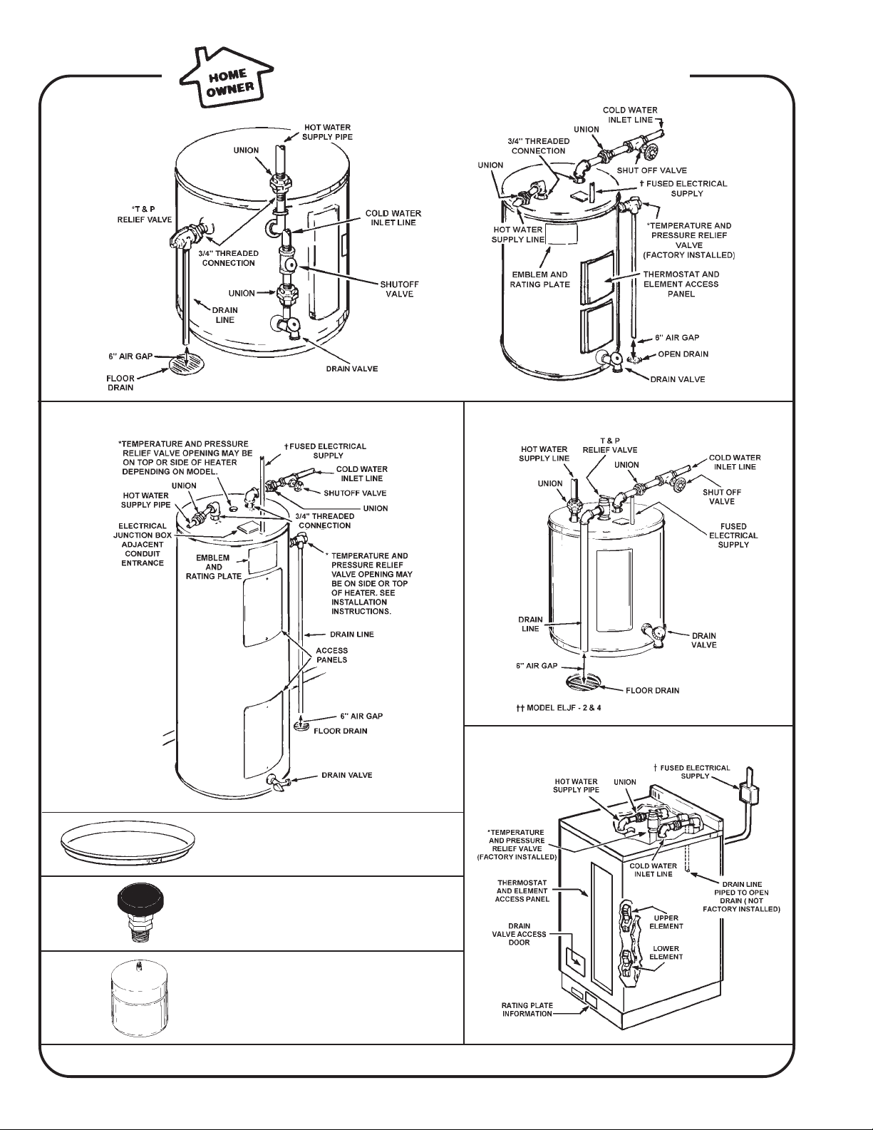
GET TO KNOW YOUR WATER HEATER
LOWBOYS
UPRIGHTS
POINT OF USE HEATERS
TABLE TOPS
INSTALL SUITABLE DRAIN PANS UNDER HEATERS
TO PREVENT DAMAGE DUE TO LEAKAGE. REFER
TO WATER HEATER LOCATION ON PAGE 3.
INSTALL VACUUM RELIEF IN COLD WATER
INLET LINE AS REQUIRED BY LOCAL CODES.
INSTALL THERMAL EXPANSION TANK OR DEVICE
IF WATER HEATER IS INSTALLED IN A CLOSED
WATER SYSTEM.
FIGURE 1
2
INSTALLATION
WARNING
FOR CALIFORNIA INSTALLATION THIS WATER HEATER MUST BE
BRACED, ANCHORED, OR STRAPPED TO AVOID FALLING OR MOVING
DURING AN EARTHQUAKE. SEE INSTRUCTIONS FOR CORRECT
INSTALLATION PROCEDURES. INSTRUCTIONS MAY BE OBTAINED FROM
YOUR LOCAL DEALER, WHOLESALER, PUBLIC UTILITIES OR
CALIFORNIA'S OFFICE OF THE STATE ARCHITECT, 400 P STREET,
SACRAMENTO, CA 95814.
REQUIRED ABILITY
INSTALLATION OR SERVICE OF THIS WATER HEATER REQUIRES ABILITY
EQUIVALENT TO THAT OF A LICENSED TRADESMAN IN THE FIELD
INVOLVED. PLUMBING AND ELECTRICAL WORK ARE REQUIRED.
GENERAL
The installation must conform to these instructions, the local code
authority having jurisdiction, and the requirements of the power company.
In the absence of code requirements follow NFPA-70 (current edition),
The National Electrical Code which may be ordered from: National Fire
Protection Association, 1 Batterymarch Park, Quincy, MA 02269.
WATER HEATER LOCATION
A minimum clearance of 4" must be allowed for access to replaceable
parts such as the thermostats, drain valve and relief valve.
TEMPERATURE AND PRESSURE RELIEF VALVE
A NEW TEMPERATURE AND PRESSURE RELIEF VALVE COMPLYING
WITH THE STANDARD FOR RELIEF VALVES FOR HOT WATER SUPPLY
SYSTEMS, ANSI Z21.22 MUST BE INSTALLED IN THE HEATER IN THE
MARKED OPENING PROVIDED. THE VALVE MUST BE OF A SIZE (INPUT
RATING) THAT WILL BE ADEQUATE FOR YOUR SIZE HEATER.
Check the metal tag on the relief valve and compare it to the heater’s
rating plate. The pressure rating of the relief valve must not exceed the
working pressure shown on the rating plate of the heater and the hourly
Btu rated temperature steam discharge capacity of the relief valve shall
not be less than the input rating of the heater. (Watts x 3.415 = Btu/hr.
rate) NO VALVE IS TO BE PLACED BETWEEN THE RELIEF VALVE AND
TANK. DO NOT PLUG THE RELIEF VALVE.
The drain line connected to this valve must not contain a reducing coupling
or other restriction and should terminate near a suitable drain to prevent
water damage during valve operation. Discharge line shall be installed
to allow complete drainage of both the valve and line. DO NOT THREAD,
PLUG OR CAP THE END OF THE DRAIN LINE.
CLOSED WATER SYSTEM
A closed system will exist if a back-flow preventer (check valve),
pressure reducing valve, or other similar device is installed in the cold
water line between the water heater and the street main (or well).
Excessive pressure may develop due to the thermal expansion of heated
water causing premature tank failure or intermittent relief valve operation.
This type of failure is not covered by the limited warranty. An expansion
tank or device may be necessary in the cold water supply to alleviate
this situation, see page 2. Contact the local plumbing authority.
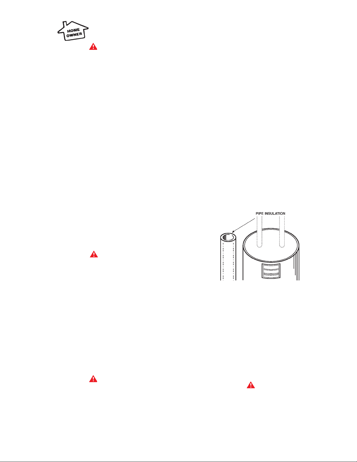
PIPE INSULATION - (SELECTED MODELS)
Adequate clearance for servicing this appliance should be considered
before installation, such as changing the anodes, etc.
The water heater should be located as close to or centralized to the
water piping system as possible. The water heater should be located in
an area not subject to freezing temperatures.
CAUTION
THE HEATER SHOULD BE LOCATED IN AN AREA WHERE LEAKAGE OF
THE TANK OR CONNECTIONS WILL NOT RESULT IN DAMAGE TO THE
AREA ADJACENT TO THE HEATER OR TO LOWER FLOORS OF THE
STRUCTURE. When such locations cannot be avoided, a suitable drain
pan piped to an adequate drain should be installed under the heater.
Such pans should have a minimum length and width of at least 2 inches
greater than the diameter of the heater and should be piped to an adequate
drain. Drain pans suitable for these heaters are available from your
distributor or Water Products Company, 5621 W. 115th Street, Alsip, IL
60803, or at www.hotwater.com/parts.
Under no circumstances is the manufacturer to be held liable for any
water damage in connection with this water heater.
HEATERS WITHOUT DRAIN VALVES:
For convenience of service, it is recommended that a drain valve be
installed in the inlet piping, as close to the heater as possible, see
page 2.
WARNING
AN ELECTRICAL GROUND IS REQUIRED TO REDUCE RISK OF ELECTRIC
SHOCK OR POSSIBLE ELECTROCUTION. THE GROUND SCREW AT THE
JUNCTION BOX IS FOR BONDING THE HEATER TO A GROUNDED SERVICE
ENTRANCE CONDUCTOR, A GROUNDED SERVICE ENTRANCE
RACEWAY, OR AN EARTH GROUNDING ELECTRODE CONDUCTOR.
WATER CONNECTIONS
See page 2 for typical installation. Make sure a suitable pipe thread
sealant is used to prevent leakage.
FIGURE 2
1. Remove pipe insulation from carton.
2. Fit pipe insulation over the incoming cold water line and the hot water
line. Make sure that the insulation is against top cover of the heater.
ELECTRICAL CONNECTIONS
The heater internal wiring conforms with one of the diagrams on
page 4. The heater data plate identifies this wiring by designation in the
space marked CIRCUIT. The voltage and wattage ratings are also shown
on the plate.
REMOVING PANELS FROM TABLE TOP MODELS
The drain valve, electrical components and wiring leads are situated
behind the two front covers (See page 2):
DANGER
1. Turn off the heater electrical supply.
2. For access to the thermostat and elements remove the two screws
on the tall front cover located on the right side facing the unit, then
remove cover. Then open the flap of installation to expose the
thermostat and element.
3. For access to the drain valve remove the one screw in the smaller
access door located in the bottom left hand side of the front panel.
4. To remove the top panel grasp the back splash and pull towards the
front sliding it toward you.
3
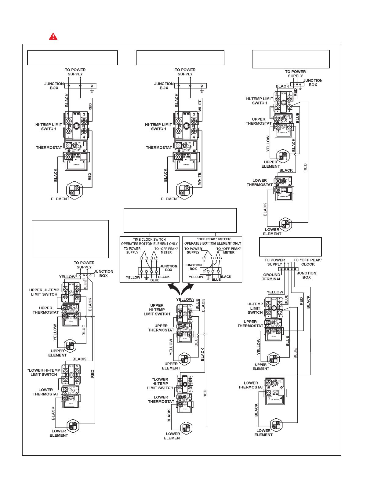
WIRING DIAGRAMS
DANGER: TURN OFF THE HEATER ELECTRICAL SUPPLY BEFORE SERVICING ANY ELECTRICAL COMPONENTS.
STANDARD SINGLE ELEMENT 240 VOLT
C-2
A-3
2 WIRE 240 VOLT POWER
SUPPLY NON-SIMULTANEOUS
OPERATION
WIRING FOR 3 WIRE
LEAD WATER HEATERS
STANDARD SINGLE ELEMENT 120 VOLT
C-2
A-3
240 VOLT “OFF PEAK” NON-SIMULTANEOUS
OPERATION BOTTOM ELEMENT ON SEPARATE TIME
CLOCK OR “OFF PEAK” METER
STANDARD WIRING FOR 2 WIRE
A-6
LEAD WATER HEATERS
A-4
WIRING FOR 4 WIRE
LEAD WATER HEATERS
*NOTE: Some Lower Hi-Temp.Limit Switches
may have 4 terminals. Use only the 2 terminals
on left.
FIGURE 3
4
*NOTE: If a 2 wire circuit is required, connect the red
and black wires together and cap. Apply power to the
blue and yellow leads only.
 Loading...