

A.O. Smith DRE 52-9, DRE 52-18, DRE 52-36, DRE 80-9, DRE 80-18 Installation And User Instructioins
...
HOT WATER STORAGE DEVICES
england
MODELS
DRE 52
DRE 80
DRE 120
INSTALLATION AND USER INSTRUCTIOINS

2
Read this manual carefully
Warning
Read this manual carefully before using the device. Not reading this manual and not
following the instructions in this manual may lead to personal injuries and damage to the
device.
Copyright © 2009 A.O. Smith Water Products Company
All rights reserved.
Nothing from this edition may be copied, reproduced and/or made public by means of
press, photocopying or in any other way without the prior written permission of A.O. Smith
Water Products Company.
A.O. Smith Water Products Company reserves the right to change the specifi cations as
mentioned in this manual.
Trademarks
All brand names mentioned in this manual are registered trademarks of the respective
suppliers.
Liability
A.O. Smith Water Products Company does not accept any liability for claims of third
parties as a result of incompetent use other than mentioned in this manual and in
conformity with the General Terms and Conditions as fi led with the Chamber of
Commerce.
For further information see the General Terms and Conditions. These can be obtained
from us free of charge.
Although utmost care has been taken in ensuring a correct and, where necessary,
complete description of the relevant parts, the manual may contain errors and some things
may be unclear.
Should you still discover faults or things which are unclear, please inform us about this. It
helps us to further improve the documentation.
Additional information
If you have any remarks or questions concerning specifi c subjects related to the device,
please do not hesitate to contact:
A.O. Smith Water Products Company
P.O. Box 70
5500 AB Veldhoven
The Netherlands
Telephone: (free) 0800 - AOSMITH
0800 - 267 64 84
General: +31 40 294 25 00
Fax: +31 40 294 25 39
E-Mail: info@aosmith.nl
Website: www.aosmithinternational.com
For problems with respect to connections to electricity and water supplies, please contact
the supplier/installation engineer of your installation.

3
TABLE OF CONTENTS
1. GENERAL ........................................................................................... 4
1.1 Device Description ............................................................................................ 4
1.2 Regulation and Safety ..................................................................................... 5
1.2.1 Boil Dry Protection ............................................................................................ 7
1.2.2 Checking the Float Switch ................................................................................ 8
1.3 Technical description ........................................................................................ 9
1.4 Technical Data ................................................................................................ 10
2. FOR THE INSTALLER ..................................................................... 12
2.1 Installation procedures .................................................................................... 12
2.1.1 General Installation ......................................................................................... 12
2.1.2 Water Connections ......................................................................................... 12
2.1.3 Electrical Connection ..................................................................................... 12
2.1.4 Electrical Diagrams ......................................................................................... 13
2.2 Putting into operation ...................................................................................... 17
2.2.1 Filling the Device ............................................................................................ 17
2.2.2 Putting Into Operation ..................................................................................... 17
2.2.3 Putting out of Operation .................................................................................. 17
2.2.4 Temperature Regulation ................................................................................. 18
2.3 Maintenance ................................................................................................... 18
2.3.1 Sacrifi cial anode ............................................................................................. 18
2.3.2 Descaling ........................................................................................................ 18
2.4 Steps When There is a Fault .......................................................................... 18
2.4.1 Water Temperature Not Good ......................................................................... 19
2.4.2 Presumed Water Leakage .............................................................................. 19
2.4.3 Fault Table ...................................................................................................... 20
2.5 Spare Parts ..................................................................................................... 20
3. FOR THE USER ...............................................................................21
3.1 Instructions for Use ......................................................................................... 21
3.1.1 Filling the Device ............................................................................................ 21
3.1.2 Putting into operation ...................................................................................... 21
3.1.3 Use ................................................................................................................. 21
3.1.4 Putting out of operation ................................................................................... 22
3.2 Maintenance ................................................................................................... 22
3.3 Faults .............................................................................................................. 22
4. WARRANTY ..................................................................................... 23
4.1 General Warranty............................................................................................ 23
4.2 Tank Warranty ................................................................................................. 23
4.3 Conditions of installation and use ................................................................... 23
4.4 Exclusions ....................................................................................................... 24
4.5 Extent of the warranty ..................................................................................... 24
4.6 Claims ............................................................................................................. 24
4.7 No obligations for A.O. Smith other than those specifi ed here. ...................... 24

4
1. GENERAL
1.1 Device Description
The structure and equipment for this
electrical heating device are in accordance
with the European standard for electrical
household devices (EN 60335-1:2002
+ A11:2004 + A1:2004 + A12:2006
+ A2:2006 en EN 60335-2-21:2003
+ A1:2005) The device thus meets
the European Directive for Electrical
Household Devices and has the right to
bear a CE mark.
The device is suitable to be used with
an operating pressure of up to 8 bar
(= 800 kPa). The tank is made of steel
plate, which has a glass lined coating
on the inside. The tank is also provided
with two sacrifi cial anodes to give extra
protection against corrosion. A thick CFC
free polyurethane insulation layer, covered
with a steel casing, prevents unnecessary
heat loss. The device is fully fi lled with
water and continually starts under water
pipe pressure. When hot water is drawn off
from the device, it is immediately topped
up with cold. Incoloy heating elements are
used for good transfer of heat.
To create extra comfort in case of long
pipelines, circulating piping with a
circulating pump may be connected to
the piping. The circulating pipeline can be
connected to the cold-water supply.
5
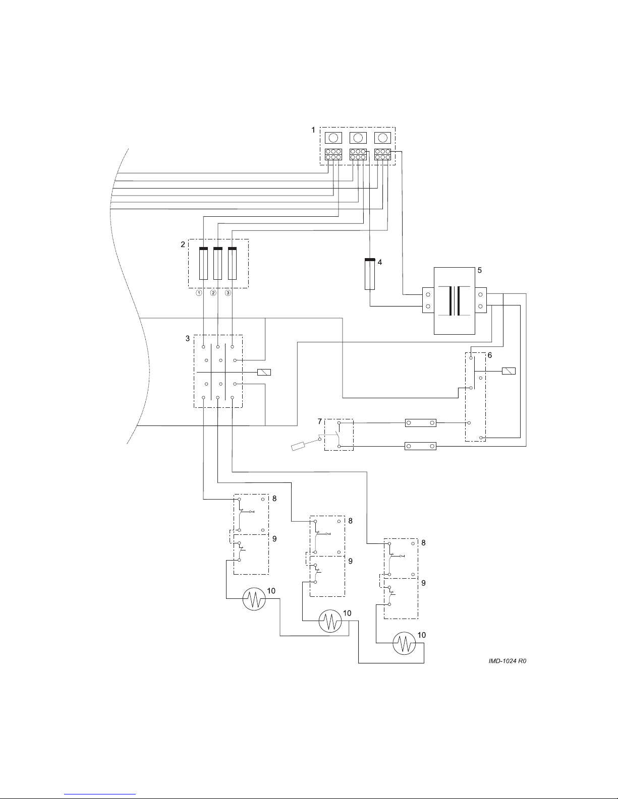
Fig. 1 - regulation and safety
1.2 Regulation and Safety
For clarifi cation see the diagram below:
(the image is an extract from the electrical
diagram further on)

6
3 relays (3) and a control current
transformer (5) are fed from the main
connection block (1). The main circuit
is protected by 30 Amp T fuses.
The transformer (400V to 24V) is
primarily secured with T0,2 A (4). A boil
dry protection mechanism (in the form of
a fl oat switch) (7) is included in the 24V
current control circuit. (The fl oat switch
is indicated diagrammatically. See boil
dry protection further on for more precise
explanation) The control current circuit is
closed if there is water in the device (fl oat
switch). In this case an auxiliary relay (6)
is used which in turn switches the relay
(3). The relays determine whether the
electrical elements are fed.
The elements are fed via the relay (3).
The wire goes to the maximum thermostat
(8) via the relays (2). The maximum
thermostat has a reset button. The output
from the maximum thermostat goes to the
regulating thermostat (9). The element
(10) is fed from the regulating thermostat.
During normal operation the regulating
thermostat (9) switches the element (10)
on and off. If a temperature of above
93°C occurs on an element the maximum
thermostat (8) locks the element. In order
to put the element back into operation the
reset button of the maximum thermostat
must be pressed in. The temperature
must have dropped by approximately
20°C before the maximum thermostat can
be reset.
If the temperature of the water above in
the tank exceeds 98°C for any reason,
the combined temperature and pressure
safety device (T&P valve) will open.
The safety control circuit will be interrupted
if the water level drops to below the fl oat
switch (7) or if the device is switched on
while empty.
The device is then switched off completely.
This is to prevent the elements coming
into operation while there is insuffi cient
water present in the device (boil dry
protection).
The safety fuses, 30 Amp T for 600 V can
be ordered retrospectively from A.O. Smith.
7
1.2.1 Boil Dry Protection
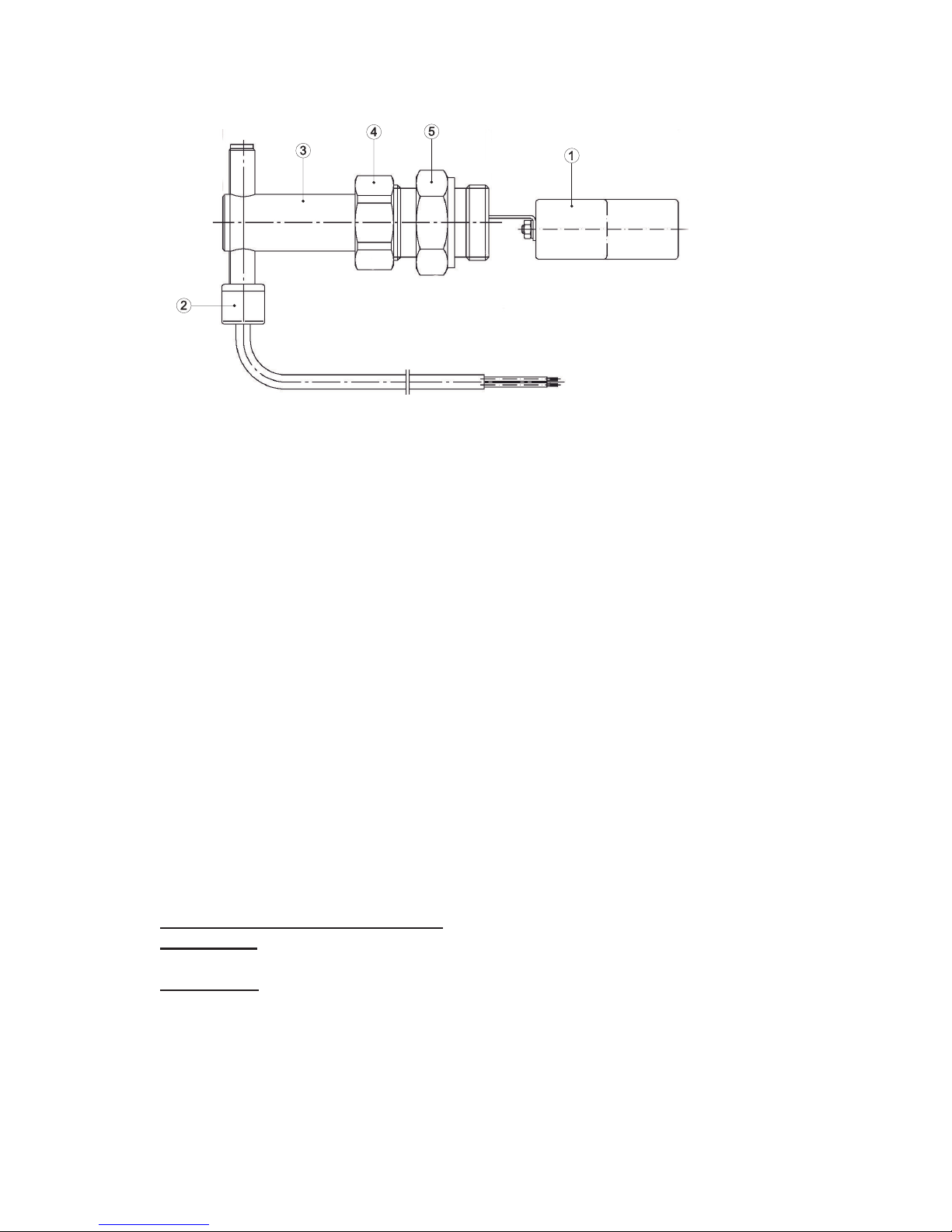
Fig. 2 - fl oat switch
The boil dry protection mechanism
consists of a fl oat switch which monitors
the water level approximately halfway
up the tank above the elements. If there
is insuffi cient water present in the tank,
then the fl oat (1) hangs down. If the tank
is fi lled with water then the fl oat is moved
upwards by the water. In the electrical
diagram the fl oat switch is reproduced
diagrammatically. The actual process
is as follows: the fl oat arm moves a
magnet with respect to the reed-contact
(2) which is located in the black plastic
tube at the end of the fl oat switch. The
movement of the magnet changes the
magnetic fi eld and the reed-contact is
closed.
The exposure height (3) of the reed
contact is very important.
This is 14 mm. This setting may not
be changed!
Explanation:
With an exposure height of 14 mm the
switch point is approximately halfway
along the stroke of the fl oat.
If the exposure height is set lower, then
the switch point shifts upwards. If the
exposure height is too small the contact
will no longer connect even if the fl oat
is completely above it. In this case the
device will not come into operation.
If the exposure height is set lower than
14 mm , then the switch point shifts
downwards. This means that the contact
will already connect upon a small
upwards movement of the fl oat. If the
exposure height is set too high then the
contact is permanently closed and the
safety mechanism does not work. This
means that the elements can come into
operation without there being suffi cient
water present in the device. This will lead
to the elements burning out in a very
short time and short circuit and leakage.
So never change the exposure height.
The reed contact and the fl oat must
always be vertical. The arrow on the
clamping plate on the front must point
upwards. The fl oat switch is secured in
the tank with nut (5). By loosening nut
(4) the fl oat switch can be set vertically.
Nut (4)
is sealed with an o-ring with respect to
nut (5). The fl oat switch must be taken
out of the device as a complete unit
for checking or replacement. (The fl oat
cannot be passed through the opening in
nut (5).) For this purpose the device thus
has to be drained.

8
1.2.2 Checking the Float Switch
Switch off the feed voltage and remove
the fuses from the elements. In this
way the control circuit can be tested
without the elements being put into
operation. Drain the device until the
water is defi nitely below the fl oat switch.
If desired the fl oat switch can now be
removed for visual inspection. Check
the resistance of the contacts with a
multimeter and check whether the switch
point is situated approximately halfway
along the stroke of the fl oat. (For new
contacts this resistance is between 1
and 1.5 Ohms). Screw the fl oat switch
back into the tank and place it vertically.
Check the exposure height. Close the
door and connect the feed voltage. The
safety relays must not come in. (The
tautening and release of the safety
relays is clearly audible.) Now allow
water to fl ow into the device. If the water
presses the fl oat upwards, the fl oat
switch closes the control circuit and the
safety relays will tauten. Then drain the
device once again. The lowering of the
water level will lead to the fl oat switch
blocking the control circuit once again
and the safety relays will release. Repeat
this operation at least one time.
Switch off the feed voltage and fi t the
fuses of the elements again. Close the
door and reconnect the feed voltage.
 Loading...