

A. O. Smith BTN-120 Service Manual
M O D E L S C O V E R E D
BTN Models 120 through 400 (A)
Series 100 through 108
(BTN Meets Low NOx Requirements
of SCAQMD Rules 1121 and 1146.2)
BTR Models 151, 201
Induced Draft Multi-Flue
Commercial Water Heaters
Part No. 317923-000 • Printed in the U.S.A. • 0810

BTN,BTR 151/201 TANK TYPE COMMERCIAL
GAS WATER HEATER SERVICE HANDBOOK
Table of Contents
BTN, BTR 151/201 SERVICE HANDBOOK INTRODUCTION..............................................2
QUALIFICATIONS..................................................................................................................3
TOOLS REQUIRED...............................................................................................................3
INSTALLATION CONSIDERATIONS - CLEARANCES.........................................................4
TOP AND FRONT VIEWS OF MINIMUM CLEARANCES TO COMBUSTIBLES..................4
MINIMUM CLEARANCE TO COMBUSTIBLES.....................................................................5
REQUIRED EXTERIOR CLEARANCES................................................................................6
AIR SUPPLY..........................................................................................................................7
INSUFFICIENT MAKEUP AIR ........ NEGATIVE AIR PRESSURE .....DOWNDRAFTS........7
MAKE-UP AIR – DIRECT COMMUNICATION WITH OUTDOORS.......................................8
CONTAMINATED AIR............................................................................................................9
AIR FOR COMBUSTION – FLAMMABLE ITEMS..................................................................9
GAS VALVE....................................................................................................................
GAS VALVE.........................................................................................................................11
VENTING.............................................................................................................................12
VENTING – MULTIPLE CATEGORY I GAS WATER HEATERS.........................................12
VENT TABLES FOR CATEGORY I - TYPE B GAS VENT..................................................13
VENT TABLES FOR CATEGORY I - TYPE B GAS VENT..................................................14
VENT TABLES FOR CATEGORY I - TYPE B GAS VENT..................................................15
VENT TABLES FOR CATEGORY I - TYPE B GAS VENT..................................................16
VENT TABLES FOR CATEGORY I - TYPE B GAS VENT..................................................17
BTN /BTR 151,201 SEQUENCE OF OPERATION..............................................................18
DRAFT PROVING PRESSURE SWITCH - SETTINGS.......................................................19
THERMOSTAT AND IGNITION CONTROL BOARD VIEW.................................................20
WHITE RODGERS INTEGRATED CONTROL - THERMOSTAT........................................21
WHITE RODGERS IGNITION CONTROL BOARD..............................................................22
GAS CONTROL VALVE/BURNER AREA VIEW..................................................................23
WIRING DIAGRAM..............................................................................................................24
ELECTRICAL SEQUENCE – BTN / BTR151,201................................................................25
OPERATING SEQUENCE – FLOW CHART........................................................................26
DIAGNOSTIC SEQUENCE OF OPERATION – FLOW CHART..........................................27
PRE-SERVICE CHECKLIST................................................................................................28
TEST 1 - 120 VAC CHECK TO HEATER.............................................................................29
HEATER CONTROL BOARD DIAGNOSTIC LED INTERPRETATION AND
TROUBLESHOOTING.........................................................................................................29
IGNITION CONTROL BOARD DIAGNOSTIC LED INTERPRETATION AND
.....10
A. O. Smith Water Heaters 1 Technical Training Department
Ashland City, Tennessee 7002 ©

BTN,BTR 151/201 TANK TYPE COMMERCIAL
GAS WATER HEATER SERVICE HANDBOOK
TROUBLESHOOTING..........................................................................................................30
TEST 2 - POLARITY CHECK...............................................................................................31
TEST 3 - CONTINUITY CHECK OF HIGH LIMIT (ECO)......................................................32
TEST 4 - UPPER TEMPERATURE PROBE CONTINUITY CHECK....................................33
TEST 5 - CALLING FOR HEAT – NO INDUCER OPERATION...........................................34
TEST 6 - INDUCER ON.............NO IGNITION.....................................................................35
TEST 7 - INDUCER ON – PROVER SWITCH AND LOW GAS SWITCH CLOSED
...................NO IGNITER OPERATION................................................................................36
TEST 8 - IGNITER HEATS – NO MAIN BURNER................................................................37
TEST 9 - IGNITER HEATS – NO MAIN BURNER................................................................38
TEST 10 - MAIN BURNER IGNITION FOR LESS THAN 5 SECONDS...............................39
TEST 11 - WATER HEATER SHUTTING OFF BELOW SETTIN
DISPLAY LIGHTS ON INTEGRATED HEATER CONTROL................................................41
GENERAL QUESTIONS AND ANSWERS ..........................................................................50
BTN, BTR 151/201 SERVICE HANDBOOK INTRODUCTION
This service handbook is a supplement to the BTN and BTR151/201 Installation and
Operation Manual. The handbook provides information on servicing and troubleshooting A.O.
Smith BTN/BTR151,201/ water heaters in the field. While this handbook is not intended to be
all inclusive, it contains:
G......................................40
• step-by-step procedures with illustrations to verify proper installation, operation,
and troubleshooting
• quick reference data to assist in servicing the product line
• answers to common questions encountered in the operation of the product line.
The handbook is intended to be used by licensed plumbing professionals. Reference should
be made to the installation manual accompanying the product. If you are experiencing a
problem not covered in this handbook, please contact the A.O. Smith Technical Information
Departmen
representative for further assistance. No duplication or reproduction of this book may be made
without the expressed written authorization of the A.O. Smith Water Products Company.
t at 1-800-527-1953 or your local A.O. Smith Water Products Company
A. O. Smith Water Heaters 2 Technical Training Department
Ashland City, Tennessee 7002 ©

BTN,BTR 151/201 TANK TYPE COMMERCIAL
GAS WATER HEATER SERVICE HANDBOOK
QUALIFICATIONS
Installation or service of this water heater requires ability equivalent to that of a licensed
tradesman in the field involved. Plumbing, air supply, venting, gas supply and electrical testing
skills are required.
TOOLS REQUIRED
• Phillips head screwdriver
• standard screwdrivers
• 3/8 and 7/16 inch open end wrench
• set of marked drill bits
• electrical multimeter tester capable of measuring continuity, AC voltage and DC
voltage
• gas pressure gauge or manometer
• water pressure gauge
• thermometer
• 1/2 inch socket with extension for removal of the clean out cover
• 1-1/16 inch socket with extension for anode removal
Rev. 1 - Adds multi-flue models. BTN and are identical except for nitrous
oxide (NOx) emission bars over main burner ports on BTN models.
Rev. 2 - Corrected clearance table illustration errors and clarified troubleshooting
procedures.
Rev. 3 Adds BTR 151 & 201 models. Adds BTN Series 108 to parts list. BTI models
no longer in production.
A. O. Smith Water Heaters 3 Technical Training Department
Ashland City, Tennessee 7002 ©
BTN,BTR 151/201 TANK TYPE COMMERCIAL
GAS WATER HEATER SERVICE HANDBOOK
INSTALLATION CONSIDERATIONS - CLEARANCES
This portion of the handbook reviews some often overlooked installation considerations
clearances, air supply, gas pressure requirements, and venting—taking note of necessary
installation requirements for BTN and BTR151,201 . The installation manual covers most of
these items in detail.
A 24-inch clearance for all serviceable parts is recommended. Clearances may vary between
models. See instruction manual or the label on the heater for clearances applicable to your
specific model.
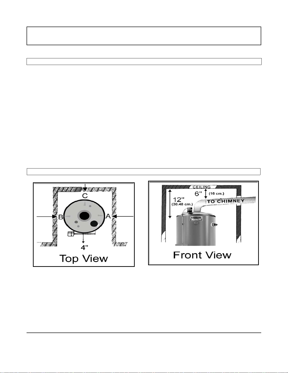
TOP AND FRONT VIEWS OF MINIMUM CLEARANCES TO COMBUSTIBLES
A. O. Smith Water Heaters 4 Technical Training Department
Ashland City, Tennessee 7002 ©

BTN,BTR 151/201 TANK TYPE COMMERCIAL
GAS WATER HEATER SERVICE HANDBOOK
MINIMUM CLEARANCE TO COMBUSTIBLES
Model Number "A" Right Side "B" Left Side "C" Back "D" Ceiling
-120 2" 2" 2" 12"
-154 1" 1" 1" 12"
-180 thru 199 3" 3" 3" 12"
-200/A thru 275/A 2" 2" 2" 12"
-310 thru 400/A 3" 3" 3" 12"
BTN-120 thru
200A
BTN-250/A thru
310/A
BTN-366 6" 6" 6" 6"
BTN-400 4" 4" 4" 4"
2" 2" 2" 12"
3" 3" 3" 12"
BTR 151 & 201 2” 2” 2” 12”
A, B, and C clearances to non-combustibles is “0” inches - a 12 inch clearance to cover remains
unchanged.
A. O. Smith Water Heaters 5 Technical Training Department
Ashland City, Tennessee 7002 ©
BTN,BTR 151/201 TANK TYPE COMMERCIAL
GAS WATER HEATER SERVICE HANDBOOK
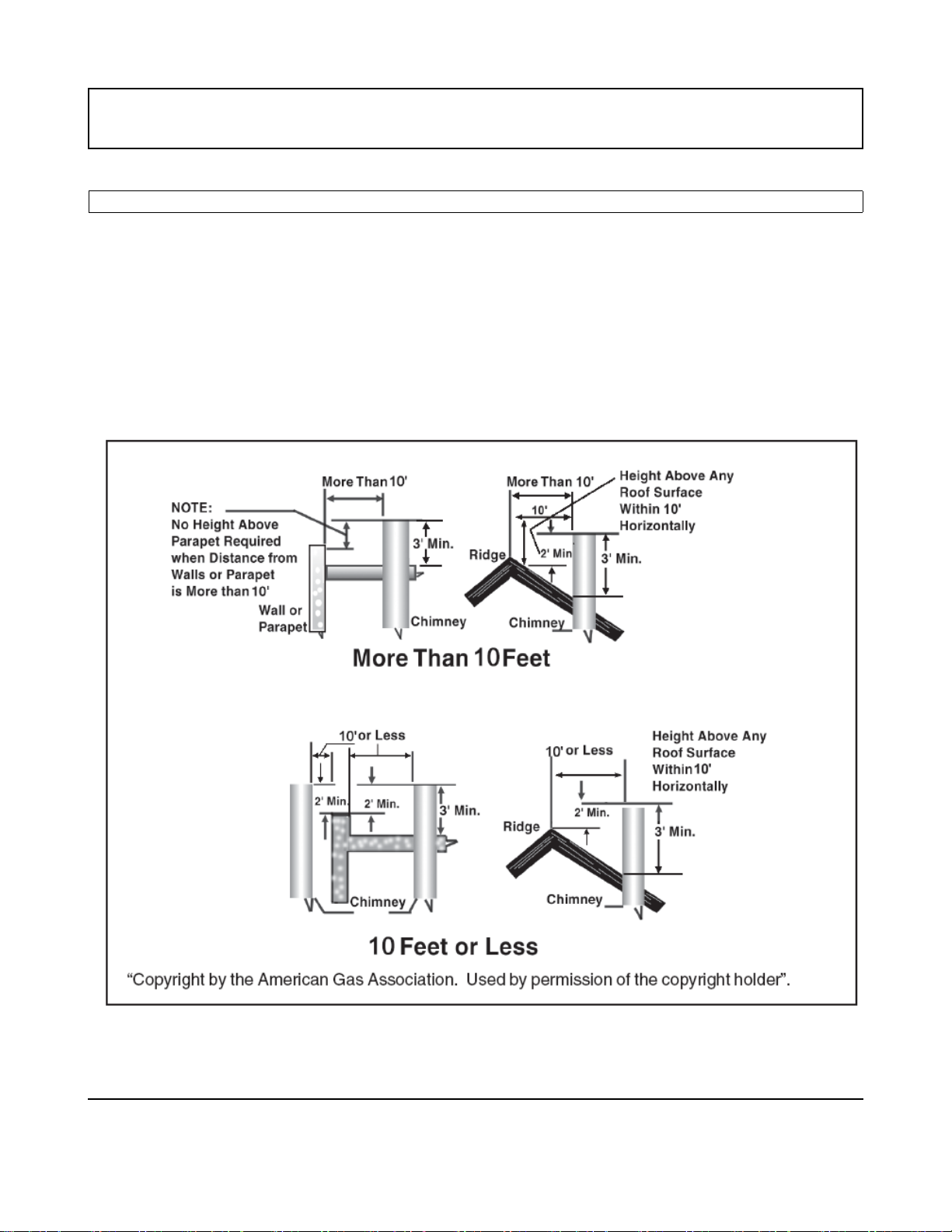
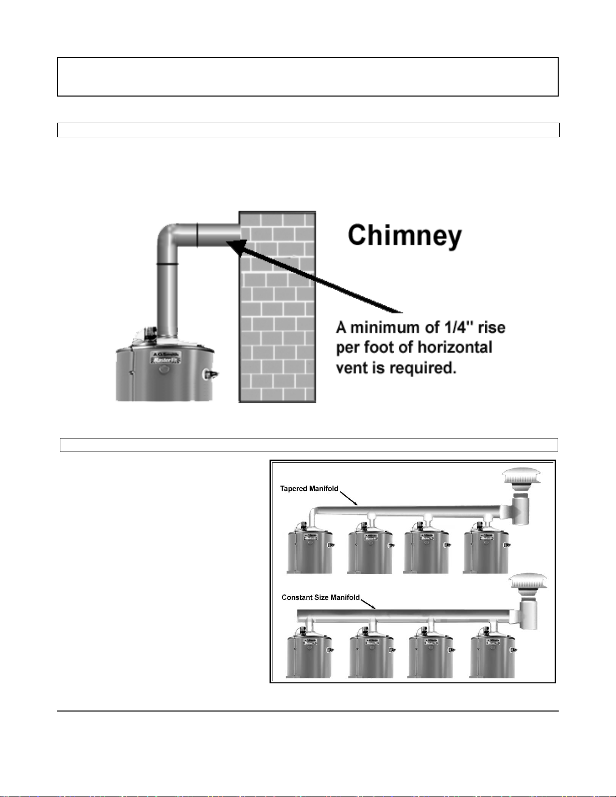
REQUIRED EXTERIOR CLEARANCES
The illustration below shows the required clearances for venting units using natural draft
venting.
The vent must extend at least 3 feet above the highest point where it passes through a roof of
a building and at least 2 feet higher than any portion of a building within a horizontal distance
of 10 feet (for vents of 12 inches in diameter or less).
References: NFPA 54 ANSI Z 223.1 may allow reduction to 8 feet with
a “listed vent cap.”
“
Copyright by the American Gas Association. Used by permission of the copyright holder”.
A. O. Smith Water Heaters 6 Technical Training Department
Ashland City, Tennessee 7002 ©
BTN,BTR 151/201 TANK TYPE COMMERCIAL
GAS WATER HEATER SERVICE HANDBOOK
AIR SUPPLY
Stoichiometric or theoretical complete combustion requires 10 cubic feet of air per 1,000
BTUH of gas supplied. The National Fuel Gas code also recommends an additional 2.5 cubic
User-Defined Index
feet of “excess” air. For information on minimum make-up air opening sizes for various
building installations, refer to the National Fuel Gas Code NFPA 54, ANSI Z223.1, Sec. 5.3
10 Cubic
10 Cubic
Feet
Feet
1,000
1,000
BTU
BTU
+
+
+
+
Com. Air
Com. Air
2.5 Cubic
2.5 Cubic
Feet
Feet
Excess
Excess
Air
Air
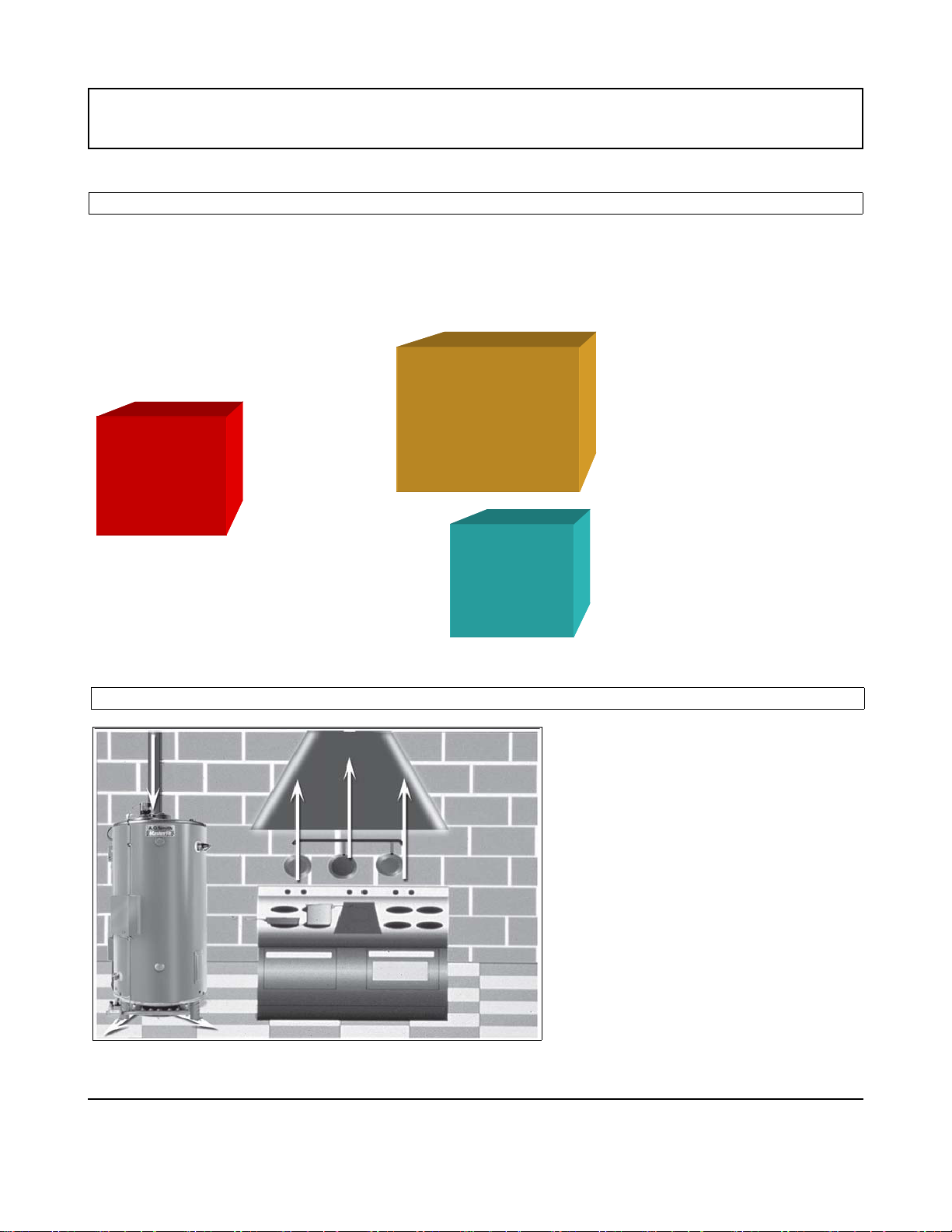
INSUFFICIENT MAKEUP AIR ........ NEGATIVE AIR PRESSURE .....DOWNDRAFTS
One common example is in a
restaurant installation where
exhaust vent equipment was not
considered in sizing make-up
requirements. This condition may
result in air being back drafted by
the restaurant exhaust equipment
through the heater causing the draft
proving switch to open and/or
erratic heater shutdown.
A. O. Smith Water Heaters 7 Technical Training Department
Ashland City, Tennessee 7002 ©
BTN,BTR 151/201 TANK TYPE COMMERCIAL
GAS WATER HEATER SERVICE HANDBOOK
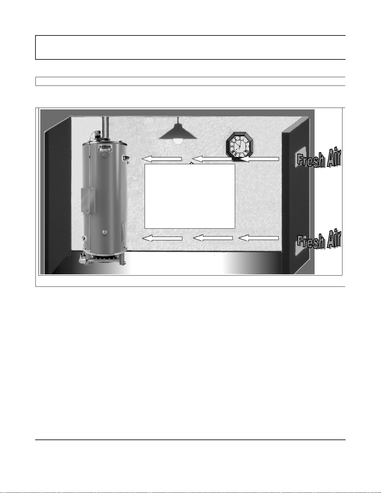
MAKE-UP AIR – DIRECT COMMUNICATION WITH OUTDOORS
A fresh supply of make-up air for combustion can be supplied to the heater through
make-up air ducts, which directly communicate with the outdoors.(Not Direct Vent)
1 SQUARE INCH PER
4,000 Btu FOR EACH
OPENING
Two openings are required: one within 12 inches of the top of the enclosure and one within 12
inches of the bottom of the enclosure. Each opening must have a free area of not less than 1 square
inch per 4,000 BTUH of the total input of all appliances within the enclosure. The lower opening
primarily provides combustion air. The upper opening provides vent dilution air and acts as a relie
opening for flue gases should the vent become obstructed or a downdraft condition occur.
Additionally, when the heater is installed in a confined space and communicating with the outdoor air,
one permanent opening, beginning with
permitted where the equipment has clearances of at least 1 inch (2.5 cm) from the sides and back
and 6 inches (16 cm) from the front of the appliance. The opening must directly communicate with the
outdoors and must communicate through a vertical or horizontal duct to the outdoors or spaces (crawl
or attic) that freely communicate with the outdoors, and must have a minimum free area of a) 1
inch per 3,000 BTUH (7cm2 per kW) of the tot
t
not less
han the sum of the areas of all vent connectors in the confined space.
in 12 inches (30 cm) of the top of the enclosure, must be
square
al input of all equipment located in the enclosure and b)
A. O. Smith Water Heaters 8 Technical Training Departmen
Ashland City, Tennessee 7002 ©
BTN,BTR 151/201 TANK TYPE COMMERCIAL
GAS WATER HEATER SERVICE HANDBOOK
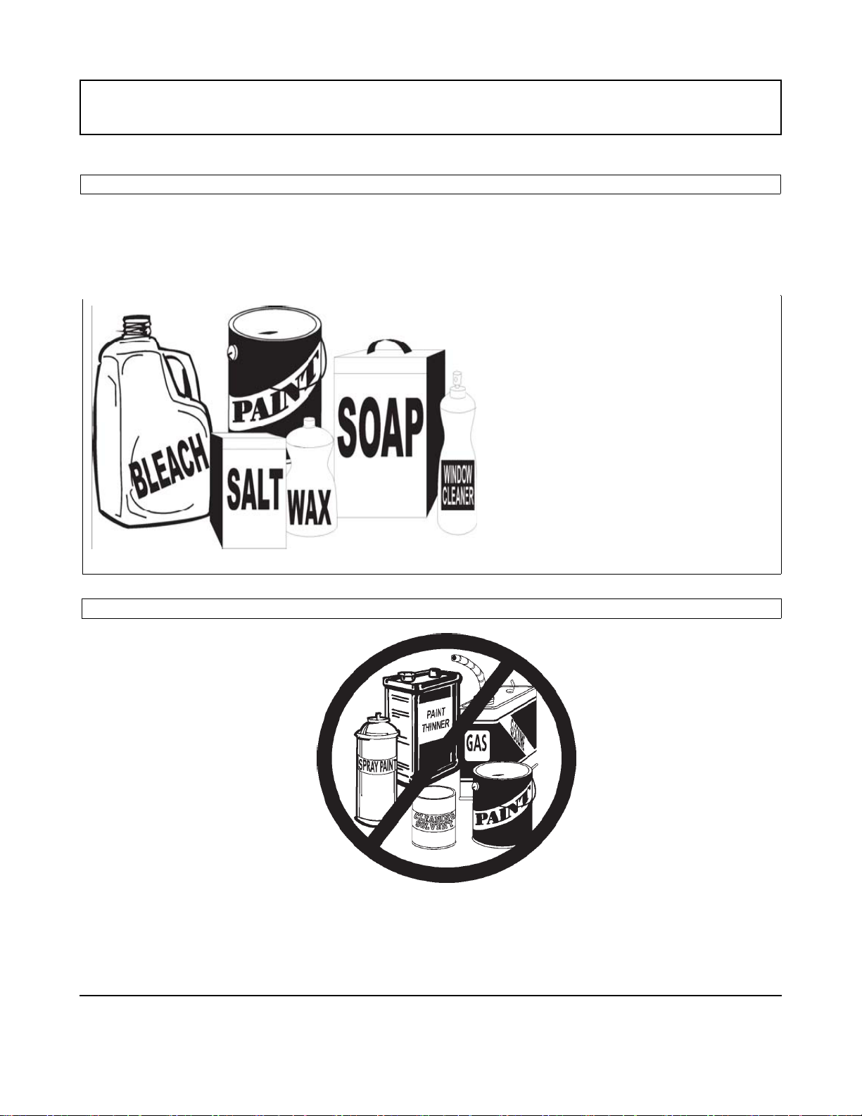
CONTAMINATED AIR
Along with adequate make-up air, the quality of the air is important. Contaminants in
combustion air can lead to premature heater failure. Vapors from bleaches, soaps, waxes,
salts, etc. are drawn into the combustion chamber with the make-up air and, once fired, mix
with water vapor in the gases to form extremely corrosive hydrochloric or hydrofluoric acid
and other corrosive by-products.
= Rust Chips
AIR FOR COMBUSTION – FLAMMABLE ITEMS
A. O. Smith Water Heaters 9 Technical Training Department
Ashland City, Tennessee 7002 ©
BTN,BTR 151/201 TANK TYPE COMMERCIAL
GAS WATER HEATER SERVICE HANDBOOK
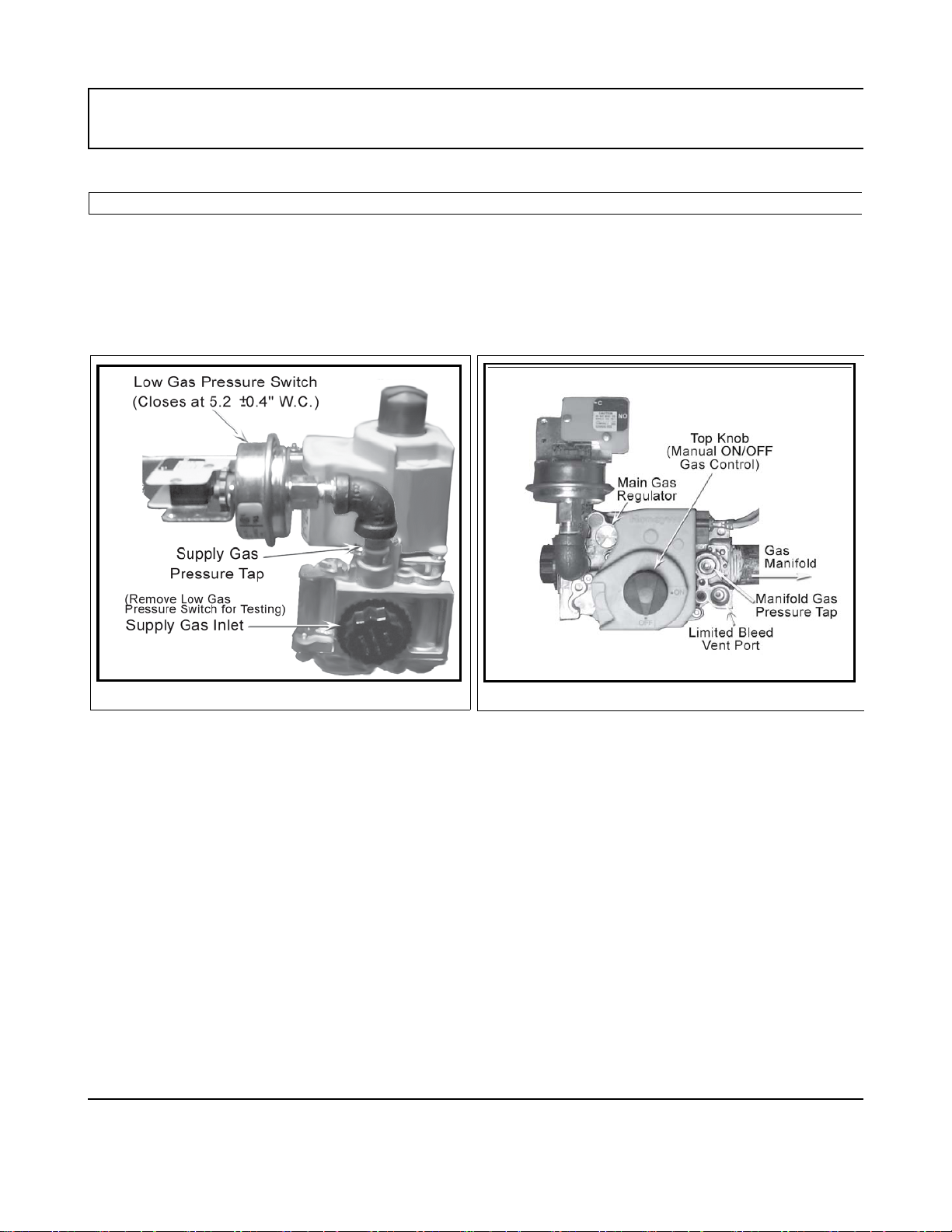
GAS VALVE
The supply gas pressure is normally measured at the gas valve inlet gas pressure tap, if
available, when the gas is flowing. The manifold gas pressure is measured at the manifold
pressure tap of the gas valve when the gas is flowing. Gas valves used are 24 volt AC
combination-step opening gas valves. They incorporate the main valve and gas pressure
regulator into one body. The Low Gas Pressure Switch, the Supply Gas Inlet, and the Supply
INLET VIEW
The top view of the gas valve, shown on the
Gas Pressure Tap are shown in the Inlet View to the right.
right, shows the Main Gas Regulator, Manifold Pressure Tap, Top Knob, and the Limited
Bleed Vent Port. The main gas regulator is found under the silver cap (silver cap for Natural
Gas or black cap for Propane) screw. It is factory preset to 3.5 inches W.C. and
adjusts gas pressure output from 3.0 to 5 inches water column.
manifold pressure at the outlet when the gas is flowing.
A. O. Smith Water Heaters 10 Technical Training Departmen
Ashland City, Tennessee 7002 ©
TOP VIEW
Caution: Always test the
BTN,BTR 151/201 TANK TYPE COMMERCIAL
GAS WATER HEATER SERVICE HANDBOOK
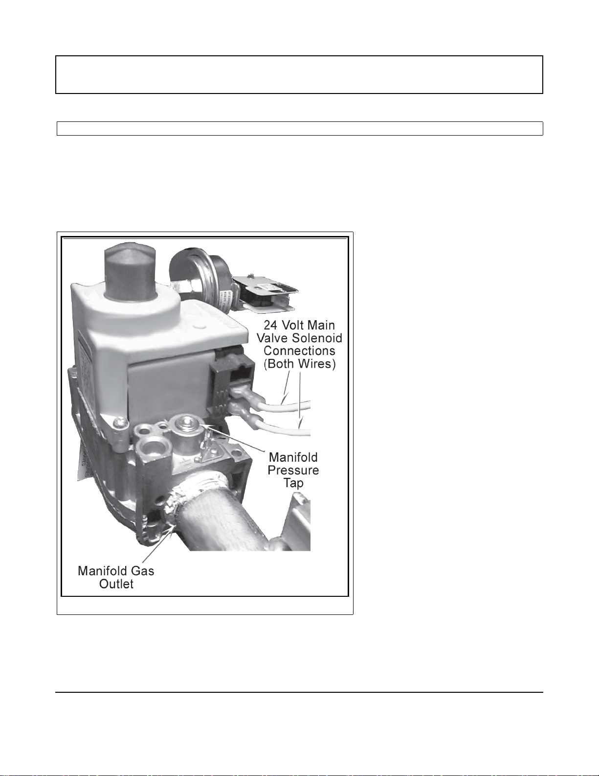
GAS VALVE
The outlet view of the Gas Valve, shown on the right, shows the Manifold Gas Outlet
Connection, the two 24 volt Main Valve (MV) Solenoid connections, and the Manifold
Pressure Tap. The two yellow wires from the 12-pin plug on the Ignition Board attach to the
MV terminals.
OUTLET VIEW
A. O. Smith Water Heaters 11 Technical Training Department
Ashland City, Tennessee 7002 ©
BTN,BTR 151/201 TANK TYPE COMMERCIAL
GAS WATER HEATER SERVICE HANDBOOK
VENTING
All , BTN, and BTR water heaters are classified by ANSI as Category I (non-condensing,
negative pressure venting) appliances. They are approved for type B vent. The draft inducer
does not pressurize the exhaust.
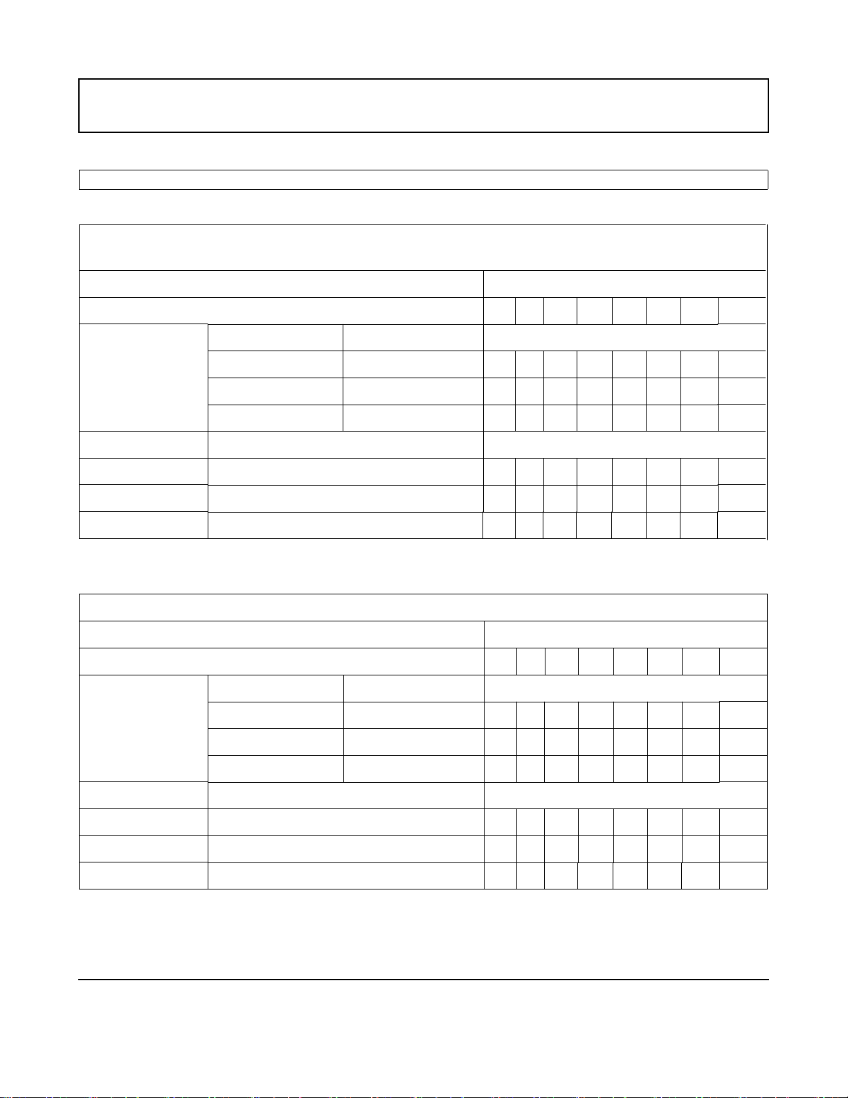
VENTING – MULTIPLE CATEGORY I GAS WATER HEATERS
For larger applications BTN and
BTR151,201 water heaters can be
common vented together, either in a
tapered manifold or constant size
manifold.
Follow the National Fuel Gas Codes
requirements for sizing and
installation of fan-assisted products.
,BTN, and BTR 151/201 models may
be common vented only with other
Category I appliances.
See the Venting Section in the
National Fuel Gas Code.
A. O. Smith Water Heaters 12 Technical Training Department
Ashland City, Tennessee 7002 ©

BTN,BTR 151/201 TANK TYPE COMMERCIAL
GAS WATER HEATER SERVICE HANDBOOK
VENT TABLES FOR CATEGORY I - TYPE B GAS VENT
Multiple Gas Fired Tank-Type Heaters
When venting multiple Category I tank type heaters using Type B vent pipe, follow the
installation tables below which give sizing and data based upon NFPA 54/ANSI Z223.1-2006.
Model: BTN/ 120
latoT.rh/utB 000,021:tupnI Vent Height (feet)
001050302510186”5 :eziS rotcennoC tneV
Input Btu/hr Rise Vent Connector Diameter (inches)
120,000 1' 6 6 5 5 5 5 5 5
120,000 2' 5 5 5 5 5 5 5 5
120,000 3' 5 5 5 5 5 5 5 5
No. of Units Combined Input (Btu/hr x 1,000) Combined Vent/Manifold Diameter
66666677000,0422
66677788000,0633
67788999000,0844
Model: BTN 154; BTR 151
T.rh/utB 000,451/000,051:tupnI otal Vent Height (feet)
001050302510186”6 :eziS rotcennoC tneV
Input Btu/hr Rise Vent Connector Diameter (inches)
150,000/154,000 1' 6 6 6 6 6 6 6 6
150,000/154,000 2' 6 6 6 6 6 6 6 6
150,000/154,000 3' 6 6 6 6 6 6 6 6
No. of Units Combined Input (Btu/hr x 1,000) Combined Vent/Manifold Diameter
2 300,000/ 308,000 7 7 6 6 6 6 6 6
3 450,000/ 462,000 8 8 7 7 7 6 6 6
4 600,000/ 616,000 9 9 9 8 8 7 7 6
A. O. Smith Water Heaters 13 Technical Training Department
Ashland City, Tennessee © 2007

BTN,BTR 151/201 TANK TYPE COMMERCIAL
GAS WATER HEATER SERVICE HANDBOOK
VENT TABLES FOR CATEGORY I - TYPE B GAS VENT
Model: BTN 180,199, 200; BTR 201
Input:180,000, 190,000 and 199,000 Btu/hr. Total Vent Height (feet)
Vent Connector Size: 6” 6 8 10 15 20 30 50 100
Input Btu/hr Rise Vent Connector Diameter (inches)
180,000 1' 7 7 6 6 6 6 6 6
190,000 1' 7 7 7 6 6 6 6 6
199,000 1' 7 7 7 6 6 6 6 6
180,000 2' 6 6 6 6 6 6 6 6
190,000 2' 7 6 6 6 6 6 6 6
199,000 2' 7 7 6 6 6 6 6 6
180,000 3' 6 6 6 6 6 6 6 6
190,000 3' 6 6 6 6 6 6 6 6
199,000 3' 6 6 6 6 6 6 6 6
No. of Units Combined Input (Btu/hr x 1,000) Combined Vent/Manifold Diameter
360,000
2
380,000
398,000
540,000
3
570,000
597,000
720,000
4
760,000
796,000
7 7 6 6 6 6 6 6
7 7 7 6 6 6 6 6
7 7 7 6 6 6 6 6
7 6 6 6 6 6 6 6
7 6 6 6 6 6 6 6
6 6 6 6 6 6 6 6
6 6 6 6 6 6 6 6
6 6 6 6 6 6 6 6
6 6 6 6 6 6 6 6
A. O. Smith Water Heaters 14 Technical Training Department
Ashland City, Tennessee © 2007
BTN,BTR 151/201 TANK TYPE COMMERCIAL
GAS WATER HEATER SERVICE HANDBOOK
VENT TABLES FOR CATEGORY I - TYPE B GAS VENT
Model: BTN 250
Input:250,000 Btu/hr. Total Vent Height (feet)
Vent Connector Size: 6” 6 8 10 15 20 30 50 100
Input Btu/hr Rise Vent Connector Diameter (inches)
250,000 1' 8 8 7 7 7 6 6 6
250,000 2' 7 7 7 7 6 6 6 6
250,000 3' 7 7 7 7 6 6 6 6
No. of Units Combined Input (Btu/hr x 1,000) Combined Vent/Manifold Diameter
2 500,000 9 9 9 8 8 7 7 7
3 750,000 12 12 10 10 10 9 8 8
4 1,000,000 14 14 12 12 10 10 9 9
Model: BTN 275
latoT.rh/utB 000,572:tupnI Vent Height (feet)
001050302510186”6 :eziS rotcennoC tneV
Input Btu/hr Rise Vent Connector Diameter (inches)
275,000 1' 8 8 7 7 6 6 6 6
275,000 2' 8 8 7 7 6 6 6 6
275,000 3' 7 7 7 7 6 6 6 6
No. of Units Combined Input (Btu/hr x 1,000) Combined Vent/Manifold Diameter
2 550,000 10 9 9 8 8 8 7 7
3 825,000 12 12 12 10 9 9 8 8
4 1,100,000 14 14 14 12 12 10 9 9
A. O. Smith Water Heaters 15 Technical Training Department
Ashland City, Tennessee © 2007
 Loading...