

Page 1

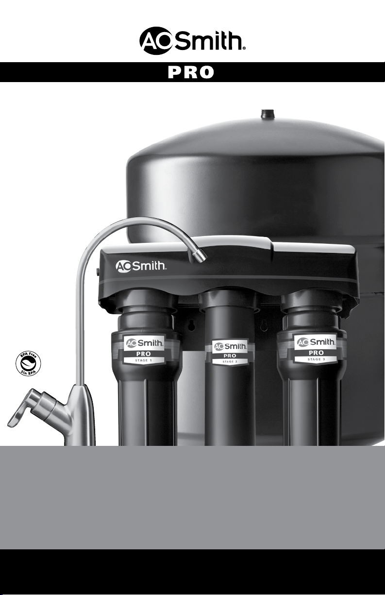
OWNER'S MANUAL
Use this owner's manual to reference installation,
troubleshooting and lter replacement information.
If you need help or have a question,
we've got you covered.
Give us a call at 833.232.9711
Page 2
AOW-3000
REVERSE OSMOSIS
With Claryum
Osmosis inversa con Claryum
Owner’s Manual / El manual del proprietario
®
®
Page 3
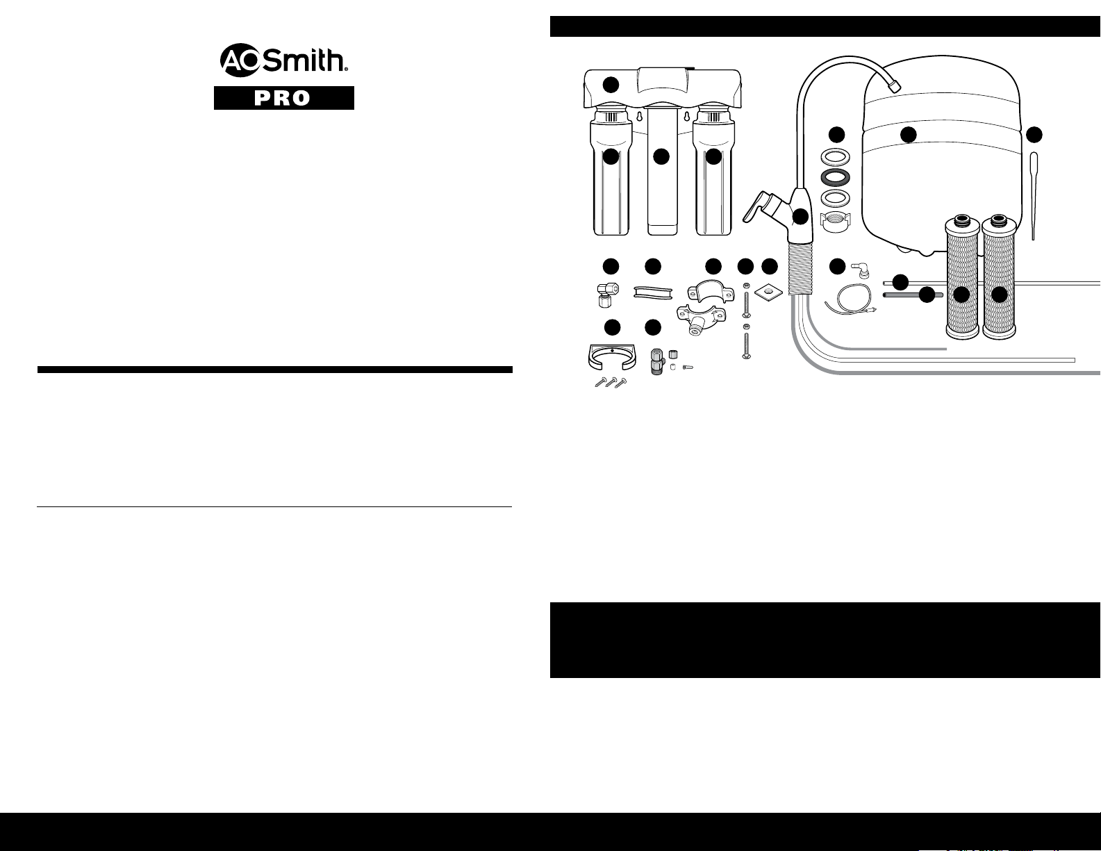
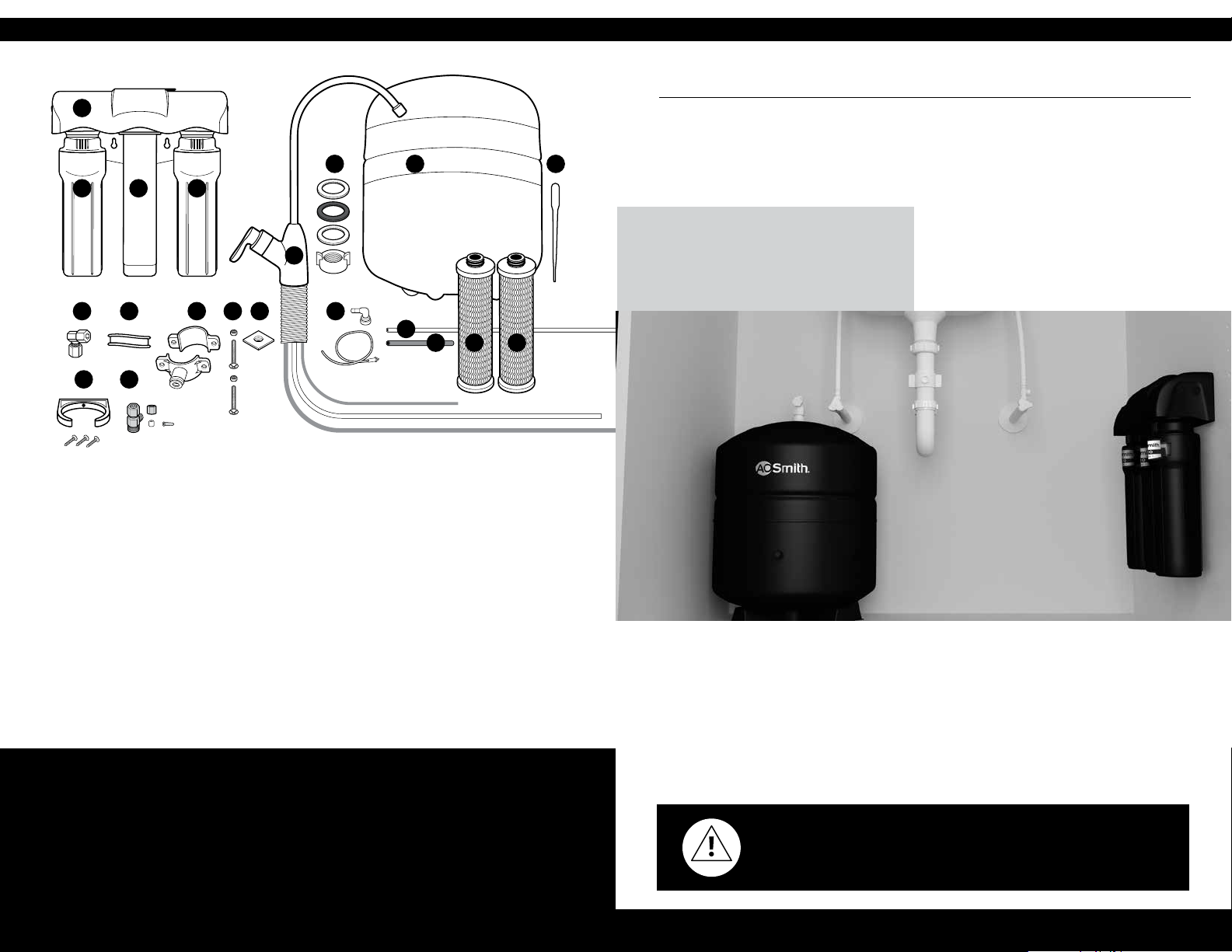
BOX CONTENTS
A
1
A. O. Smith has designed, engineered and built this ltration system to last. It
features Claryum
®
ltration that reduces harmful contaminants – those you can
see, smell and taste, and those you can’t – with no chemical additives. Whatever
your water need – from hydration to cooking, early morning coffee,
smoothies, or soup, you will now have ltered water.
Keep this owner’s manual to reference installation, troubleshooting
and lter replacement information.
If you need help or have a question, we’ve got you covered.
Give us a call at 833.232.9711.
AOW-3000
REVERSE OSMOSIS
With Claryum
TABLE OF CONTENTS
Box Contents ............................................................................................................1
®
B C D
JI J K
S T
A SYSTEM MANIFOLD
B CARBON FILTER SUMP
C MEMBRANE FILTER
CARTRIDGE
D CLARYUM
®
FILTER SUMP
E FAUCET WITH TUBING
F GASKET, NUT,
WASHER, SPACER
G WATER STORAGE TANK
F H
E
L
M
N
H EYEDROPPER
I TANK CONNECTOR
J PLUMBER’S TAPE
K DRAIN CONNECTOR
L NUTS & BOLTS
M FOAM SEAL
N FLOW RESTRICTOR
& 90° ELBOW
O TUBING ¼" WHITE
G
O
P Q R
1/4" RED
3/8" WHITE
3/8" RED
P TUBING 3/8" RED
Q CARBON FILTER
CARTRIDGE
R CLARYUM
CARTRIDGE (BLUE)
S SCREWS & BRACKET
T BRASS TEE
®
FILTER
Installation Guide ............................................................................................... 2-11
Care and Maintenance ..................................................................................... 12-14
Please read entire manual to ensure all parts listed are present before installation.
If any part is missing or damaged let us know by calling 833.232.9711.
Do not attempt to install the lter.
Performance Data Sheet ........................................................................................15
Warranty .................................................................................................................16
Spanish/Español ......................................................................................................17
Tools recommended for installation:
• Tape Measure
• Utility Knife
• Phillips Head Screwdriver
• 1/8" & 7/32" Drill Bits/Drill
• Adjustable Wrench
• Bleach
• Safety Glasses
• Pencil
• Masking Tape
• Pan or Bucket
Note: We recommend using
an approved or certied
professional if drilling is
required. Basic plumbing
knowledge is recommended
prior to installing this unit.
NEED HELP? GIVE US A CALL 833.232.9711 NEED HELP? GIVE US A CALL 833.232.9711
Page 4
2 3
INSTALLATION GUIDE
Prepare site and plan for installation
Prior to installation, read the entire manual to familiarize yourself with the System,
and determine the best location for installation. Ensure you check and comply with all
local plumbing codes.
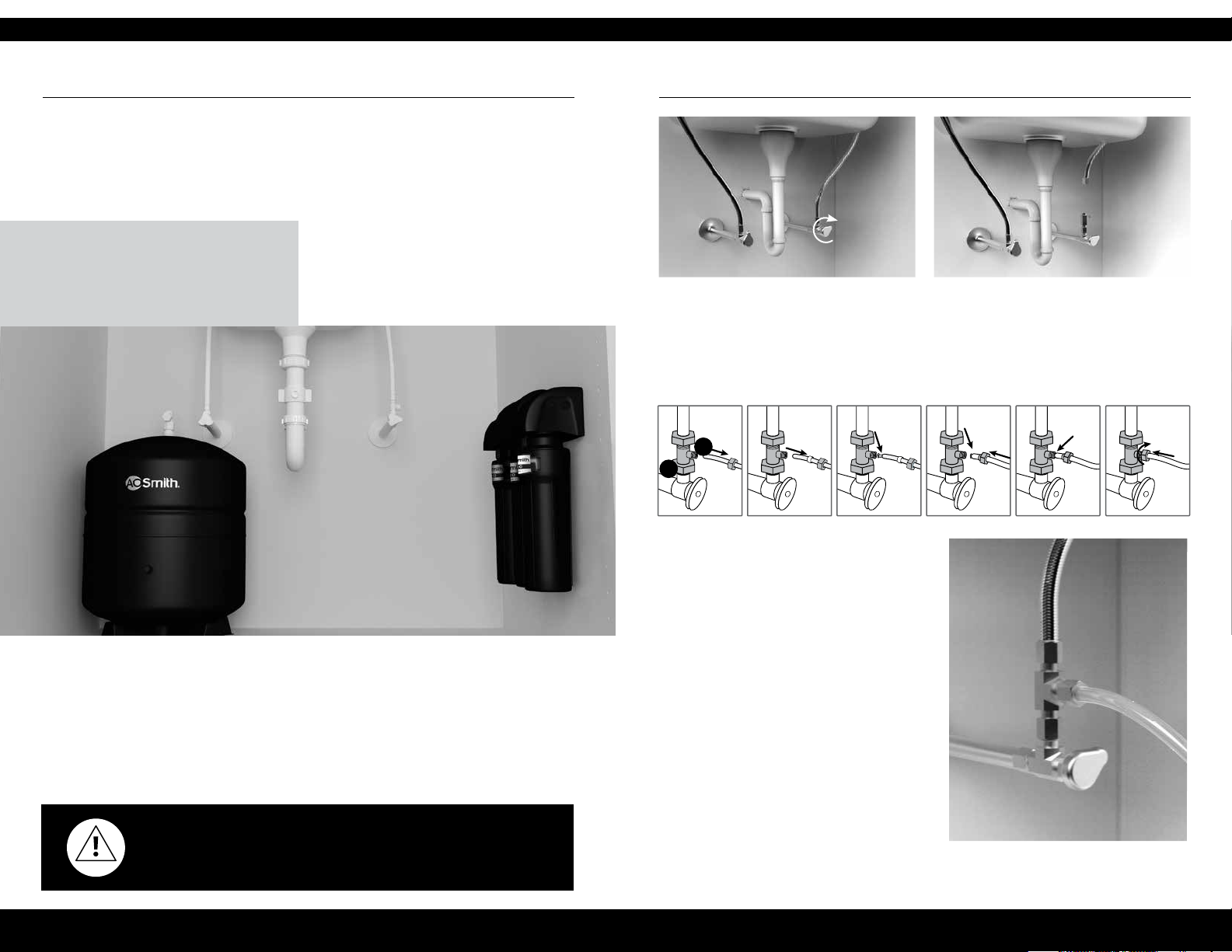
Note: If you have metal drain pipes,
TIP
Temporarily place System Manifold and Tank
into the under sink cabinet or desired location to
ensure adequate space and proper positioning.
consult a plumber for installation of
drain connection.
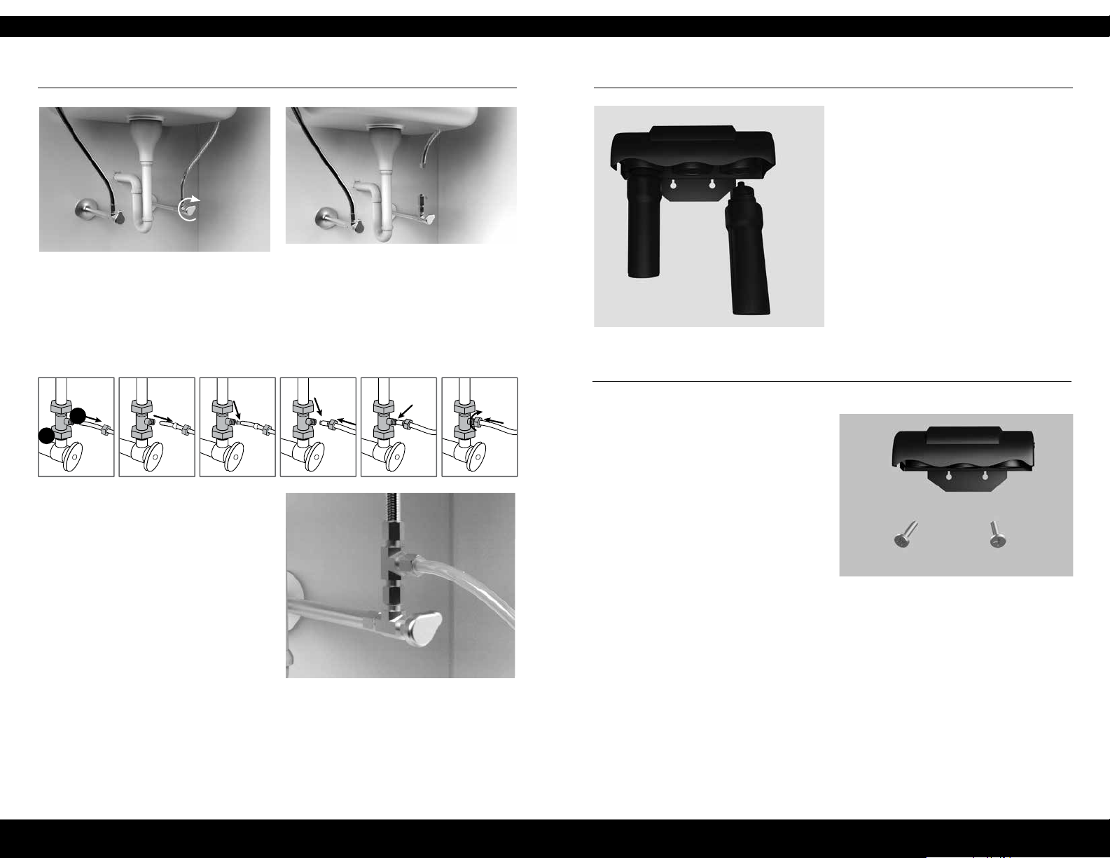
STEP 1 - Install Brass Tee Fitting
1 Turn off the cold water supply to
the sink.
2 Turn on the kitchen cold water faucet
to release pressure and allow water to
drain from the line.
P
U
A
3 Disconnect the cold water line from
the threaded stem on the cold water
shut-off valve. Attach threaded ends
of supplied brass tee to the cold water
supply line and shut-off valve; tighten
using an adjustable wrench.
4 Attach ¼" white tube to the brass tee: Slide
compression nut onto the white
tubing (with threads of nut facing end
of the tube).
Next, slide the plastic sleeve onto the
tube. Place brass insert into opening of
the white tube.
Pre-installed 3/8" white faucet tubing will be used to connect faucet to the Tank, then
to the Manifold. Measure the tubing from the faucet hole to the outlet of the System
Manifold. Ensure the remaining tubing will be sufcient to connect Manifold to Tank.
Do not cut tubing before following instructions below.
Remove System and Tank from under your sink to begin installation.
Push tip of the white tube into
opening of the brass tee.
Slide the compression nut onto
the threads of the brass tee.
While holding the white tube in place
inside the brass tee, tighten compression
nut to compress plastic sleeve and create
a seal.
WARNING: We recommend using an approved or certied professional.
Proper installation is the responsibility of the installer. Product failure due
to improper installation is not covered under the warranty.
Do not connect the other end at this time.
Note: Use a wrench to ensure complete seal. Avoid over-tightening.
NEED HELP? GIVE US A CALL 833.232.9711 NEED HELP? GIVE US A CALL 833.232.9711
Page 5
4 5
INSTALLATION GUIDE
STEP 2 - Install System Manifold
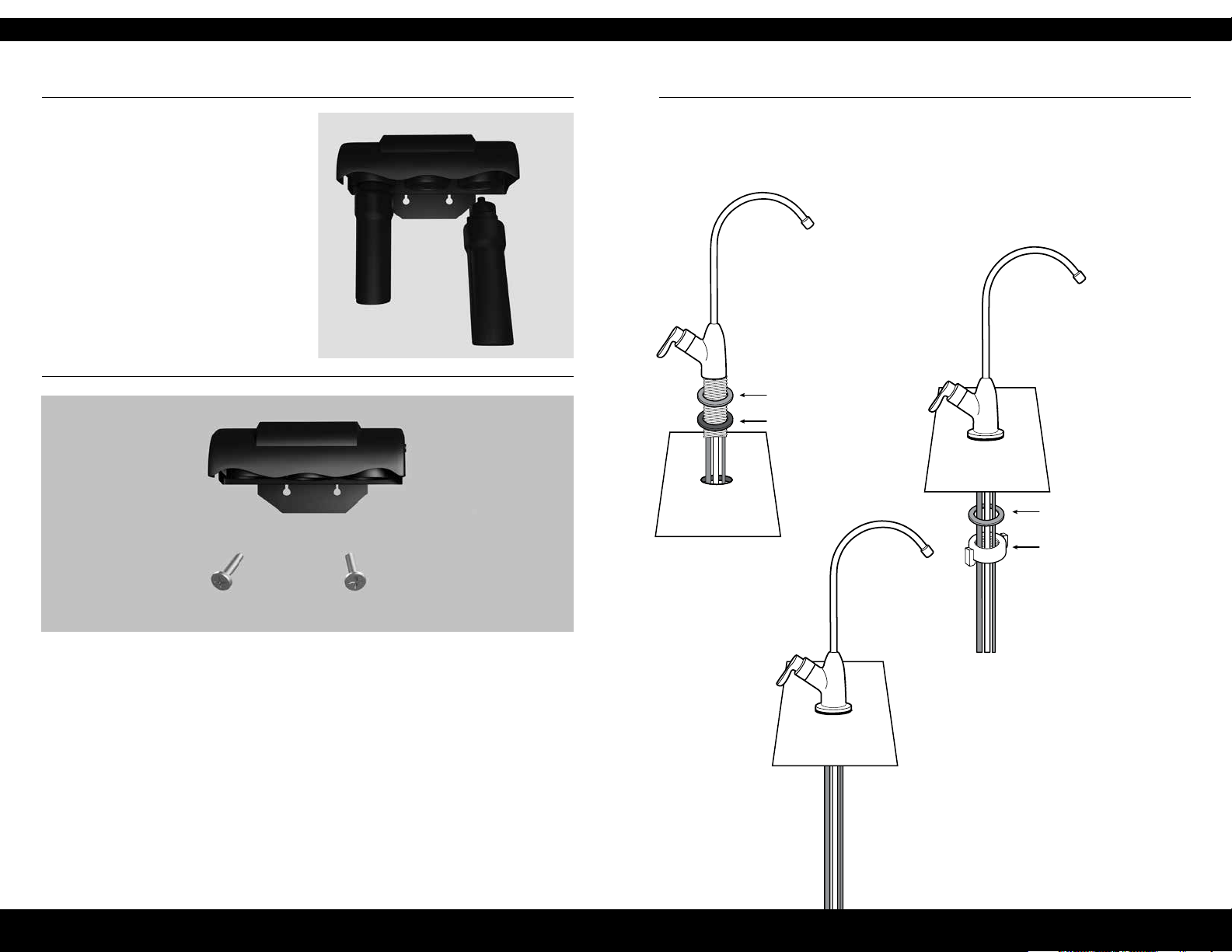
1 Select an easily accessible area under
sink to mount System Manifold. Allow
at least a 4-6" clearance to the oor
below lters to allow ample space for
lter changes.
To help gauge the right location for
your System Manifold, insert First and
Third Stage lter sumps into Manifold.
Insert sumps by aligning top connection
points and push up and to the right
until sumps are locked in.
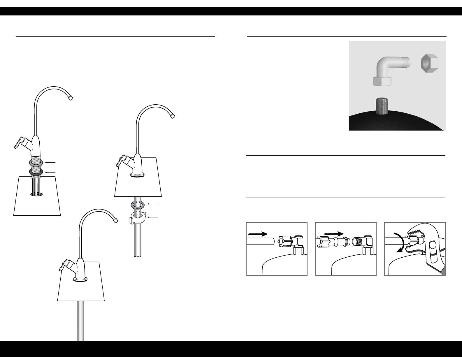
STEP 3 - Install RO faucet
You will need a sink top hole 1 1/4" in diameter for the faucet. If drilling a new
hole, ensure faucet body will mount at against surface and there is sufcient
tubing between faucet body and System Manifold.
1 Place the metal escutcheon
and black gasket on the faucet
base and feed the tubing and
faucet threads through the
countertop hole.
ESCUTCHEON
GASKET
2 Slide the metal washer
onto the faucet.
Thread the faucet
nut onto the faucet
threads. Tighten
by hand.
WASHER
FAUCET NUT
2 Mark wall placement for mounting
screws using the built-in bracket on
back of Manifold. Ensure holes are
as level as possible.
3 Drill two pilot holes for mounting
brackets using 1/8" drill bit for the
System Manifold.
Note: Do not drill into anything
beyond the cabinet wall.
Note: Drilling holes into solid surfaces or surfaces made of stone should only
be performed by a qualied and certied installer.
4 Insert anchors and mounting screws into
the wall leaving approximately 3/8" of
each screw exposed.
5 Remove First and Third lter sumps from
Manifold by turning each sump to the
left and pulling down before hanging
Manifold on wall. Mount Manifold on
wall and screw in place.
Note: Avoid over-tightening.
3 Measure the white 3/8" tubing from the
faucet to the manifold and cut to desired
length. Leftover tubing will connect
Manifold to Tank.
NEED HELP? GIVE US A CALL 833.232.9711 NEED HELP? GIVE US A CALL 833.232.9711
Page 6
6 7
INSTALLATION GUIDE
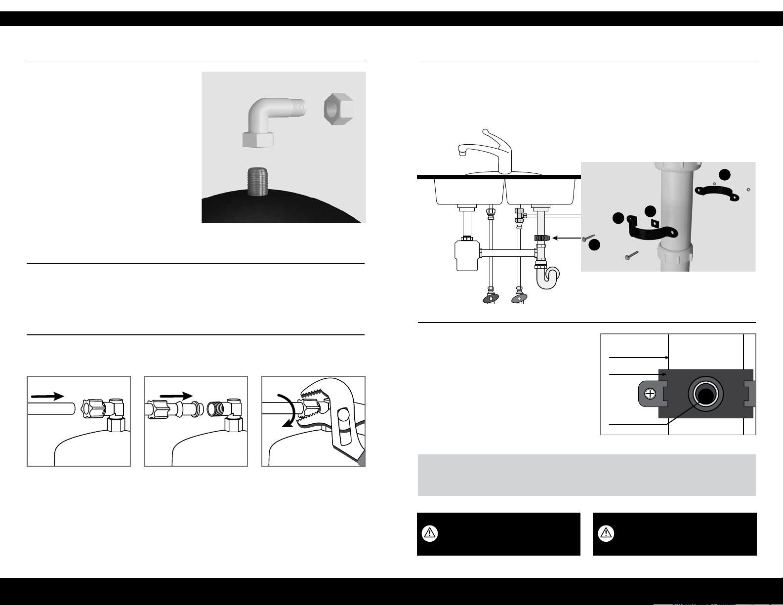
STEP 4 - Install water storage Tank
1 Apply plumber’s tape 4 or 5 times
clockwise around the nipple on top of
Tank in the same direction as threads.
2 Hand-tighten Tank connector onto
Tank nipple until secure.
Note: Do not cross thread or over-tighten.
3 Using mount stand, place Tank near the System Manifold. Using the 3/8" white
tubing leftover from the faucet install, connect one end to the Tank and the
other to the “Tank” port on the Manifold.
STEP 5 - Install drain connector
1 Identify drain outlet location. Do not install the drain connector onto the same
drain pipe as the garbage disposal. If drain-line must be installed on the same line
as garbage disposal, do not use the drain connector included. A garbage disposal
connector is recommended.
2 Remove protective cover from back of
foam seal (N).
M
L
M
N
3 Knock center hole out, align holes, and
attach to front plate of drain connector (L).
HOT COLD
4 Use drain connector to mark drill
4 Install the 3/8" white tubing to the Tank.
location on drain-line. Drill a 7/32" hole
on the drain pipe. Do not penetrate
opposite side of pipe.
DRAIN PIPE
BRACKET
5 Position the drain connector on sink
drain pipe above drain trap, allowing
room for drilling.
NEW HOLE
CAUTION Wear safety glasses to
protect eyes when drilling.
Push tubing through the
nut, collar and sleeve
into the connector.
Unscrew the compression
nut from Tank connector
to ensure tubing is
connected all the way
through the collar
and sleeve.
Slide nut to the
threads and tighten
with a wrench.
Note: Avoid
over-tightening.
6 Securely tighten nuts (M) and screws (M).
PRO TIP
If there is leakage from the drain bracket, loosen the bolts and slide the bracket up so the drilled hole is at
the bottom of the drain connector port.
WARNING Ensure that all electrical appliances
and outlets are turned off at the circuit breaker
before working in the cabinet area.
NEED HELP? GIVE US A CALL 833.232.9711 NEED HELP? GIVE US A CALL 833.232.9711
Page 7
8 9
INSTALLATION GUIDE
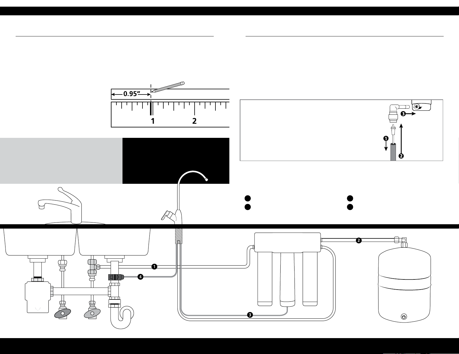
STEP 6 - Connect tubing
1 Brass Tee to Manifold “INLET”
(1/4" white tubing)
Take the white tubing leading from the
brass tee and insert it into the Manifold
port labeled “INLET”. Push the tubing
all the way in until it stops.
Diagram is actual size.
DO...
Insert tubing all the way (.95") to prevent leaking.
Wet end of tubing for an easy install into inlets and outlets.
Cut excess tubing to prevent crimping, kinks, loops or folds.
2 Manifold to Faucet
(3/8" white tubing already attached to faucet)
Insert the 3/8" white tubing (from
STEP 3 - Install RO faucet) from the
faucet into the Manifold port labeled
"FAUCET".
Depth to insert tubing
DO NOT...
Cut tubing too short. Always double-check
measurements before cutting.
Bend, crimp or kink tubing.
Discard excess tubing.
3 Manifold to Tank
(3/8" white tubing already attached to Tank)
Take the 3/8" white tubing leading from
the storage Tank and insert it into the
Manifold port labeled “Tank”. Push the
5 Faucet to Drain Connector
(3/8" red tubing from faucet)
Take the 3/8" red tubing from faucet
and insert it all the way into the drain
connector.
tubing all the way in until it stops.
4 Air Gap to RO Membrane
(1/4" red tubing from faucet)
1. Insert restrictor into the end of the red tubing.
2. Attach 1/4" red tubing to the 90° elbow until it stops.
3. Attach 1/4" 90° elbow to the membrane drain port.
Hose Connections
1/4" WHITE BRASS TEE TO MANIFOLD
1
3/8" WHITE MANIFOLD TO TANK
2
1/4" RED MEMBRANE TO FAUCET
3
3/8" RED FAUCET TO DRAIN CONNECTOR
4
WARNING:
Faucet will leak
if restrictor is not
installed.
HOT COLD
NEED HELP? GIVE US A CALL 833.232.9711 NEED HELP? GIVE US A CALL 833.232.9711
Page 8
10 11
INSTALLATION GUIDE
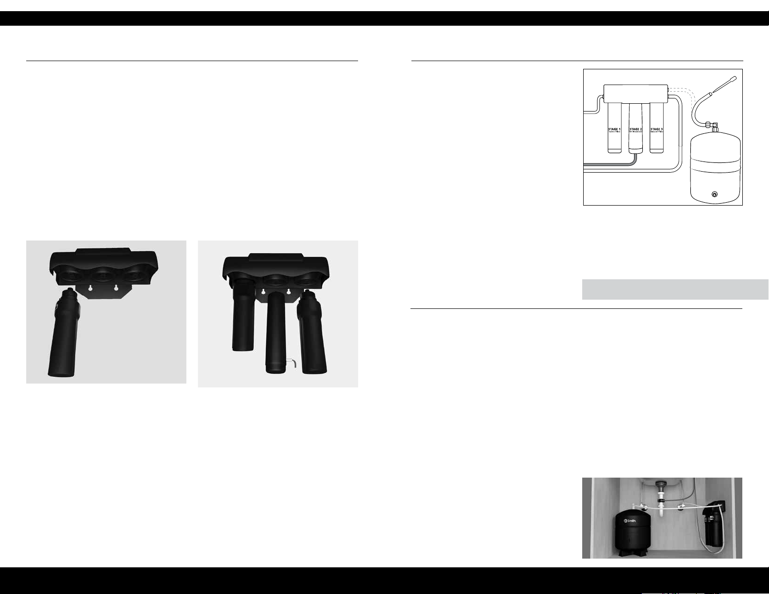
STEP 7 - Filter installation
Before you begin: Ensure the cold water valve is shut off and there is no pressure in
the System. Carbon (green caps with clear netting) and Claryum
®
(green caps with
blue netting) lter cartridges will come pre-installed in their cartridge sumps.
1 Attach Carbon sump to the First Stage
position on the inlet side of the System
Manifold. Ensure all connection points
are aligned and push the top of the
sump up and into the System Manifold.
2 Repeat step 1 for the Second Stage
RO Membrane that ts in the center,
and for the Claryum
Third Stage position on the outlet side
of the System Manifold.
®
cartridge in the
Turn the sump towards the right until
it locks.
STEP 8 - Sanitize, Test & Purge
Sanitize
1 Disconnect white tubing from the
Manifold outlet labeled “Tank”.
2 Add 3ml household bleach (5.25%)
into disconnected end of white tubing
using eyedropper (included).
Note: Handle bleach according to
manufacturer’s instructions.
3 Using the white tube, reconnect the
Tank to the Manifold outlet labeled
“Tank”. Push tubing in all the way.
4 Sanitation will be completed during
the following pressure test and purge.
Important: Bleach must be completely
removed from System before drinking
water. See purge instructions below.
Pressure Test
1 Turn on cold water supply valve to
RO Filter System.
2 Turn on kitchen faucet to purge air
from System. Turn off when water
runs smooth.
3 Conrm RO faucet is closed.
4 In approximately 2 hours, pressure will
start to build in the RO Filter System.
Carefully inspect all connections and
ttings while pressure buildup occurs.
5 Check for leaks. If leaks are found,
ensure all tubing is cut squarely and fully
inserted. Conrm there are no scratches,
dents or notches at tubing end. If so,
squarely cut 1" off of tubing and
re-insert.
Note: When RO Filter System is rst pressurized,
water may project from faucet air gap hole
until air is passed from RO Filter System.
Note: Sanitization is recommended
immediately after RO Filter System
installation and any inner-part servicing.
The person sanitizing must have clean
hands during this process.
IMPORTANT: Complete sanitization prior to pressure test.
Purge
1 Turn on RO faucet and let water
ow through System for 24 hours.
Note: Flow rate will be slow at this time.
2 Turn off RO faucet after purge
is complete.
Note: Your RO Filter System is ready for use when
purge is complete. However, you will not have ltered
water immediately. It takes 1-3 hours to completely ll
the Tank. The ow rate will be less than your kitchen
faucet. Water will run to the drain while the RO Filter
System is ltering water – even when not in use. This
is normal. Water going to drain will stop automatically
when Tank is at capacity.
NEED HELP? GIVE US A CALL 833.232.9711 NEED HELP? GIVE US A CALL 833.232.9711
Page 9

12
CARE AND MAINTENANCE
13
AOW-3000
Replacement cartridge AO-4000-CARBON
and AO-RO-RM-R
1
Membrane Production
Membrane TDS Reduction
System Production
TDS Reduction
Max TDS 1000 ppm
Max water hardness @ 6.9pH 10 gpg (2.64 gpL)
Max Chlorine in water 3.0 ppm
Supply water pH limits 4-10
Drain (reject water) Flow 3-5x product ow
Empty Storage Tank Precharge 5-7 psi air (35-48 kPa)
Storage Tank Capacity
Supply water pressure limits 40-100 psi (275-689 kPa)
Supply water temperature limits 40-100° F (5-37° C)
Efciency3 17.91%
4
Recovery
29.43%
35 gpd (132 lpd)
1
2
13.32 gpd (50.4 lpd)
2
96.3%+ average
2
3.2 gallons (12.11 liters)
95% minimum
Specications – Qualied System
Performance
Because the performance of a Reverse
Osmosis Membrane is highly dependent
upon pressure, temperature and Total
Dissolved Solids (TDS), the following should
be used for comparison purposes only.
Industry standards measure RO Membranes
performance with no back pressure on the
product water, at 60 psig (414 kPa) and 77°F
(25°C). Further conditions on the above are
250 ppm TDS and a 30.6% recovery rate.
Production rate and TDS reduction gures
are for a new Membrane that has been
rinsed for 24 hours. The production rate of
a new Membrane can decrease by 10% per
year or more, depending upon the scaling
and fouling tendencies of the Feed Water.
Measured at 50 psi, 77°±2°F, and 717 mg/l
TDS per NSF/ANSI Standard 58.
Efciency rating is the percentage of the
inuent water to the System that is available
to the user as reverse osmosis treated water.
This measurement is taken under operating
conditions that approximate typical
daily usage.
Recovery rating is the percentage of the
inuent water to the membrane portion
of the System that is available to the user
as reverse osmosis treated water when the
System is operated without a storage Tank
or when the storage Tank is bypassed.
CAPACITY AT VARIOUS WATER PRESSURE LEVELS (WITH 5 PSI PRECHARGE) U.S. GALLONS
TOTAL VOLUME 20 PSI 30 PSI 40 PSI 50 PSI 60 PSI 70 PSI
3.2 1.4 1.8 2.0 2.2 2.4 2.5
NON-POTABLE WATER SOURCES: Do not attempt to use this product to make safe drinking water from non-potable water sources.
Do not use the System on microbiologically unsafe water, or water of unknown quality without adequate disinfection before or after the
System. This System is certied for cyst reduction and may be used on disinfected water that may contain lterable cysts.
INSTALLATIONS IN THE COMMONWEALTH OF MASSACHUSETTS: The Commonwealth of Massachusetts requires installation be
performed by a licensed plumber and does not permit the use of saddle valves. Plumbing code 248—CMR of the Commonwealth of
Massachusetts must be followed in these cases.
Nitrate/Nitrite Test Kit:
This System is acceptable for treatment
of inuent concentration of no more
than 27 mg/L nitrate and 3 mg/L nitrite in
combination measured as N.* This System
is supplied with a nitrate/nitrite test kit.
Product water should be monitored
periodically according to the instructions
provided with the test kit.
Drain Flow Restrictor
The restrictor is vital for proper operation of
RO Membrane Cartridge as it keeps water
owing through the membrane at the
proper rate ensuring the water produced
is the best quality. It is recommended the
restrictor assembly be periodically inspected
to be sure it is clean and unrestricted.
If service is required on the drain ow
assembly, disassemble and reassemble as
outlined in Step 5.
Flow rate and output are determined
by 3 factors:
1 Incoming water temperature
2 Total dissolved solids (TDS) present in
supply water
3 Incoming water pressure
Lower temperatures are directly proportional to slower ow rate. All membranes
are tested at 77°F. Incoming water temperature should not exceed 100°F. The RO
Filter System should also not be installed
in a location susceptible to freezing. The
more TDS in the supply water, the more
lter time is required. Incoming TDS should
not exceed 1000 ppm. Higher water pressure enables a higher ow rate. Pressure
must be above 40 psi for proper system
operation. You may consider installing a
permeate pump or booster pump if your
pressure is below 40 psi.
Carbon Pre-Filter &
Claryum
®
Post-Filter
- Change every 6 months*
®
The Carbon and Claryum
lter cartridges
are replaceable activated carbon
cartridges located in Stages 1 and 3. It is
recommended replacing these cartridges
at least every 6 months. You may need to
replace more often with high water usage
or high sediment level. Timely replacement
of these cartridges will protect the RO
Membrane from high levels of chlorine
and/or sediment. As these lters build up
with sediment, you may notice slower
water output.
RO Membrane Cartridge
- Change every 12 months
The RO Membrane is located in Stage
2. This membrane reduces the dissolved
solids and organic matter. Most municipally
treated water has a 7.0-7.5 pH, in this
case you would need to replace your RO
Membrane every 12 months. Membrane
life depends on pH and supply water
hardness. Higher pH shortens membrane
life by causing pin-hole leaks. When
output, water quality and production rate
decrease, it is time to replace the lter.
Remineralizer
- Change every 12 months*
The Remineralizer is Stage 4. It is
designed to provide healthy amounts
of calcium, magnesium and potassium
for great-tasting water.
*Filter life depends on water usage and
water supply quality.
Do not use with water that is microbiologically unsafe or of unknown water quality without adequate disinfection before or after the System.
Systems certied for cyst reduction may be used on disinfected waters that may contain lterable cysts.
Filter is only to be used with cold water. Systems certied for cyst reduction may be used on disinfected water that may contain lterable cysts.
NEED HELP? GIVE US A CALL 833.232.9711 NEED HELP? GIVE US A CALL 833.232.9711
Page 10
14
CARE AND MAINTENANCE
This System has been tested for the treatment of water containing pentavalent arsenic
(also known as As(V), As(+5), or arsenate) at concentrations of 0.30 mg/L or less. This System
reduces pentavalent arsenic, but may not remove other forms of arsenic. This System is
to be used on water supplies containing a detectable free chlorine residual at the System
inlet or on water supplies that have been demonstrated to contain only pentavalent
arsenic. Treatment with chloramine (combined chlorine) is not sufcient to ensure complete
conversion of trivalent arsenic to pentavalent arsenic. Please see the Arsenic Facts section
of this Performance Data Sheet for further information.
Arsenic Facts
Arsenic (abbreviated As) is found naturally
in some well water. Arsenic in water has
no color, taste or odor. It is measured by
a laboratory test. Public water utilities
must have their water tested for arsenic.
You can get the results from your water
utility. If you have your own well, you
can have the water tested. The local
health department or the state environmental health agency can provide a list
of certied labs. The cost is typically $15
to $30. Information about arsenic in water can be found on the internet at the
U.S. Environmental Protection Agency
website: epa.gov/safewater/arsenic
There are two forms of arsenic:
pentavalent arsenic (As(V), As(+5), and
arsenate) and trivalent arsenic (also called
As(III), As(+3), and arsenite). In well water,
arsenic may be pentavalent, trivalent, or a
combination of both. Special sampling procedures are needed for a lab to determine
what type and how much of each type of
arsenic is in the water. Check with the labs
in your area to see if they can provide this
type of service.
Reverse osmosis (RO) water treatment Systems do not completely remove trivalent
arsenic from water. RO Systems are very
effective at removing pentavalent arsenic.
trivalent arsenic to pentavalent arsenic.
Other water treatment chemicals such as
ozone and potassium permanganate will
also change trivalent arsenic to pentavalent arsenic. A combined chlorine residual
(also called chloramine) may not convert all
the trivalent arsenic. If you get your water
from a public water utility, contact the utility to nd out if free chlorine or combined
chlorine is used in the water System. The
AO-US-RO-4000 System is designed to
remove pentavalent arsenic. It will not
convert trivalent arsenic to pentavalent
arsenic. This System was tested in a lab. Under testing conditions, the System reduced
[0.30 mg/L (ppm) or 0.050 mg/L (ppm)]
pentavalent arsenic to 0.010 mg/L (ppm)
(the USEPA standard for drinking water)
or less. The performance of the System
may be different with your installation.
Have the treated water tested for arsenic
to check whether the System is working
properly.
The RO component of the AO-US-RO-4000
System must be replaced every 1-3 years to
ensure the System will continue to remove
pentavalent arsenic. The component
identication and locations where you can
purchase the component are listed in the
installation/operation manual.
A free chlorine residual will rapidly convert
• Efciency rating is the percentage of
the inuent water to the System that
is available to the user as reverse
osmosis treated water under operating
conditions that approximate typical
daily usage.
• Recovery rating is the percentage of
the inuent water to the membrane
portion of the System that is available
to the user as reverse osmosis treated
water when the System is operated
without a storage Tank or when the
storage Tank is bypassed.
NEED HELP? GIVE US A CALL 833.232.9711
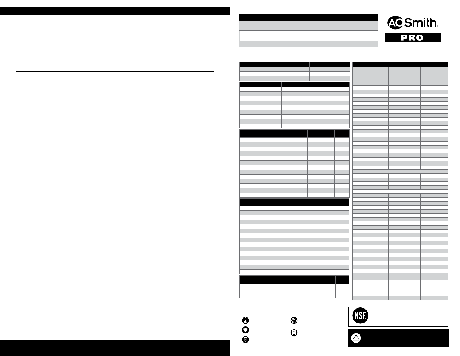
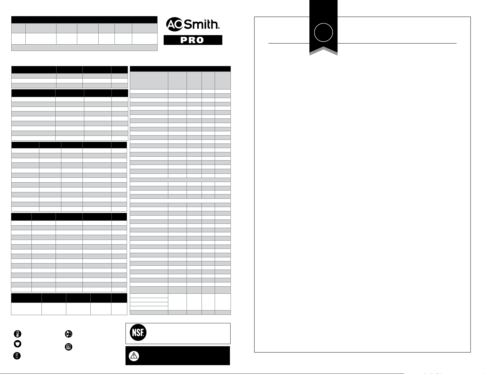
Performance Data for the Drinking Water System AO-US-RO-4000
Models Replacement Operating
AO-US-
AO-4000-CARBON
RO-4000
and AO-RO-RM-R
Manufactured by: A.O. Smith Corporation 11270 West Park Place | Milwaukee, WI 53224 | 877.333.7108
Testing Performed under NSF/ANSI Standards 42, 53, 58, 401 & P473 and in accordance with the California Department of Health Services Drinking Water Treatment Device Program.
This System has been tested according to NSF/ANSI 42, 53, 401 & P473 for reduction of the substances listed below. The concentration of the indicated substances in water entering
the System was reduced to a concentration less than or equal to the permissible limit for water leaving the System, as specied in NSF/ANSI 42, 53, 58, 401 & P473.
NSF/ANSI 42 Minimum Reduction Overall % Reduction Results
Chlorine Reduction, Free Available
Chloramine Reduction, Free Available
Particulate Reduction 85% 99.9% Pass
NSF/ANSI 53 Minimum Reduction Overall % Reduction Results
Cyst Live Cryptosporidium & Giardia 99.95% >99.99% Pass
Mercury Reduction pH 8.5 <2 ug/L >95.8% Pass
Mercury Reduction pH 6.5 <2 ug/L >96.5% Pass
Lead Reduction pH 6.5 <10 ug/L >99.4% Pass
Lead Reduction pH 8.5 <10 ug/L >99.3% Pass
MTBE Reduction <5 ug/L 86.6% Pass
Turbidity <0.5 NTU 99.1% Pass
VOC Surrogate Test 95% 99.4% Pass
Asbestos 99% >99% Pass
NSF/ANSI 58
Arsenic Pentavalent 0.30mg/L ± 10% 80.0% 97.6% Pass
Barium 10.0mg/L ± 10% 80.0% 95.2% Pass
Cadmium 0.30mg/L ± 10% 83.3% 95.3% Pass
Chromium Hexavalent 0.30mg/L ± 10% 66.7% 97.0% Pass
Chromium Trivalent 0.30mg/L ± 10% 66.7% 96.6% Pass
Copper 0.30mg/L ± 10% 56.7% 96.6% Pass
Fluoride 8.0mg/L ± 10% 81.2% 95.7% Pass
Lead .15mg/L ± 10% 93.3% 96.6% Pass
Nitrate/Nitrite 30.0mg/L ± 10% 66.7% 82.4% Pass
Radium 226/228 25pCi/L ± 10% 80.0% 80.0% Pass
Selenium 0.10mg/L ± 10% 50.0% 97.9% Pass
TDS 750mg/L ± 10% 75.0% 95.0% Pass
Turbidity 11 ± NTU 95.4% 99.1% Pass
NSF/ANSI 401
Atenolol 30 ng/L 94.2% 94.2% Pass
Bisphenol A 300 ng/L 98.80% 98.9% Pass
Carbamazepine 200 ng/L 98.6% 98.6% Pass
DEET 200 ng/L 98.7% 98.7% Pass
Estrone 20 ng/L 96.30% 96.5% Pass
Ibuprofen 60 ng/L 95.3% 95.4% Pass
Linuron 20 ng/L 96.6% 96.6% Pass
Meprobamate 60 ng/L 94.7% 94.7% Pass
Metolachlor 200 ng/L 98.6% 98.6% Pass
Naproxen 20 ng/L 96.3% 96.4% Pass
Nonyl phenol 200 ng/L 97.50% 97.5% Pass
Phenytoin 30 ng/L 95.50% 95.6% Pass
TCEP 700 ng/L 98% 98% Pass
TCPP 700 ng/L 97.8% 97.8% Pass
Trimethoprim 20 ng/L 96.7% 96.7% Pass
NSF P473
Peruorooctanoic
acid (PFOA) &
Peruorooctane
sulfonate (PFOS)
Maximum
Concentration
Inuent challenge
concentration
1.5 ±10% ug/L 0.07 ug/L 96% Pass
• All contaminants reduced by this lter are listed.
• Not all contaminants listed may be present in your water.
• Does not remove all contaminants that may be present in tap water.
Filter is only to be used
with cold water.
Filter usage must comply
with all state and local laws.
Testing was performed under
standard laboratory conditions,
actual performance may vary.
pressure range
40-100 psi
275-689 kPa
<0.5 mg/l 97.66% Pass
<0.5 mg/l 97.66% Pass
Maximum
Concentration
Minimum Reduction Overall % Reduction Results
Operating
temp. range
40-90° F
4.44-32.2° C
Minimum
Reduction
Maximum permissible
concentration
Overall % Reduction Results
Systems certied for cyst reduction
may be used on disinfected waters
that may contain lterable cysts.
See owner’s manual for general
installation conditions and needs plus
manufacturer’s limited warranty.
Recovery
Efciency
rating
rating
29.43% 17.91% 13.32 gallons
Overall %
reduction
Results
Daily
Production (DPR)
50.4 liters
Organic chemicals included by surrogate testing
VOCs
(by surrogate testing
using chloroform)
alachlor 0.002 0.050 0.001 >98%
atrazine 0.003 0.100 0.003 >97%
benzene 0.005 0.081 0.001 >99%
carbofuran 0.04 0.190 0.001 >99%
carbon tetrachloride 0.005 0.078 0.0018 98%
chlorobenzene 0.1 0.077 0.001 >99%
chloropicrin — 0.015 0.0002 99%
2,4-D 0.07 0.110 0.0017 98%
dibromochloropropane (DBCP) 0.0002 0.052 0.00002 >99%
o-dichlorobenzene 0.6 0.080 0.001 >99%
p-dichlorobenzene 0.075 0.040 0.001 >98%
1,2-dichloroethane 0.005 0.088 0.0048 95%
1,1-dichloroethylene 0.007 0.083 0.001 >99%
cis-1,2-dichloroethylene 0.07 0.170 0.0005 >99%
trans-1,2-dichloroethylene 0.1 0.086 0.001 >99%
1,2-dichloropropane 0.005 0.080 0.001 >99%
cis-1,3-dichloropropylene — 0.079 0.001 >99%
dinoseb 0.007 0.170 0.0002 99%
endrin 0.002 0.053 0.00059 99%
ethylbenzene 0.7 0.088 0.001 >99%
ethylene dibromide (EDB) 0.00005 0.044 0.00002 >99%
haloacetonitriles (HAN)
bromochloroacetontrile — 0.022 0.0005 98%
dibromoacetontrile — 0.024 0.0006 98%
dichloroacetontrile — 0.0096 0.0002 98%
trichloroacetontrile — 0.015 0.0003 98%
haloketones (HK)
1,1-dichloro-2-propanone — 0.0072 0.0001 99%
1,1,1-trichloro-2-propanone — 0.0082 0.0003 96%
heptachlor (H-34, Heptox) 0.0004 0.025 0.00001 >99%
heptachlor epoxide 0.0002 0.0107 0.0002 98%
hexachlorobutadiene — 0.044 0.001 >98%
hexachlorocyclopentadiene 0.05 0.060 0.000002 >99%
lindane 0.0002 0.055 0.00001 >99%
methoxychlor 0.04 0.050 0.0001 >99%
pentachlorophenol 0.001 0.096 0.001 >99%
simazine 0.004 0.120 0.004 >97%
styrene 0.1 0.150 0.0005 >99%
1,1,2,2-tetrachloroethane — 0.081 0.001 >99%
tetrachloroethylene 0.005 0.081 0.001 >99%
toluene 1 0.078 0.001 >99%
2,4,5-TP (silvex) 0.05 0.270 0.0016 99%
tribromoacetic acid — 0.042 0.001 >98%
1,2,4-trichlorobenzene 0.07 0.160 0.0005 >99%
1,1,1-trichloroethane 0.2 0.084 0.0046 95%
1,1,2-trichloroethane 0.005 0.150 0.0005 >99%
trichloroethylene 0.005 0.180 0.0010 >99%
trihalomethanes (THMs)
bromodichloromethane (THM)
bromoform (THM)
chloroform (THM)
chlorodibromomethane (THM)
xylenes (total) 10 0.070 0.001 >99%
System Tested and Certied by NSF International against
NSF/ANSI Standards 42, 53, 58 & 401 and conforms to
NSF protocol P473 for reduction of claims specied on the
Performance Data Sheet and at www.nsf.org.
COMPONENT
For use with municipally treated water only. Do not use with
water that is microbiologically unsafe or of unknown water
quality without adequate disinfection before or after the System.
Drinking
water
regulatory
level (MCL/
MAC) mg/L
0.080 0.300 0.015 95%
Inuent/
Unltered
Inuent/
Unltered
Efuent/
Filtered
Efuent/
Filtered
Percent
Reduction
Percent
Reduction
15
Page 11
16 17
LIMITED WARRANTY
What is covered:
This warranty covers defects in materials
or workmanship in manufacturing of
your A. O. Smith drinking water lter
Systems, except as provided below.
For how long:
This warranty runs for two years from
the date of purchase by a consumer
(“Warranty Period”).
What is not covered:
This warranty does not cover lter
cartridges and any products that were
not installed in compliance with the
instructions or that have been abused
or operated incorrectly. The limited
warranty stated herein is in lieu of any
and all warranties, expressed or implied,
whether written or oral, including but
not limited to the implied warranties of
tness for a particular purpose or the
implied warranty of merchantability.
A. O. Smith shall not be liable for any
incidental, consequential, special or
contingent damages arising directly
or indirectly from any defect or the
use of the System. Owner shall be
responsible for all labor and any other
expenses related to the removal, repair
or installation of the ltration System
or any component part. Finally, this
warranty is voided if the product is
used with parts that are not genuine
A. O. Smith parts. This includes, but
is not limited to: replacement lters,
faucets, and diverter valves.
2
YEAR
What A. O. Smith will do:
We will replace the defective part of
the covered product and send it to you
upon payment of $9.50 for shipping and
handling per incident.
How to get service:
To receive service under this
warranty, you must contact
A. O. Smith at 833-232-9711 or
[email protected]
within the Warranty Period and describe
the problem to a customer service
representative who will verify that the
product is under warranty and arrange
for delivery of a replacement part.
How state law applies:
This warranty gives you specic rights
but you may have other rights which
vary from state to state.
Some states do not allow the exclusion
or limitation of implied warranties or
incidental or consequential damages,
so the above limitation or exclusion
may not apply to you.
Warranty card:
Warranty registration is not required
for coverage under the A. O. Smith
Limited Warranty. If you purchased from
a retailer or dealer, please complete
the online warranty registration form
at www.AOSmithatLowes.com/register.
Once registered online, we will have a
record of your purchase and you will
not be required to produce a proof of
purchase for a warranty claim.
A. O. Smith diseñó este sistema de ltración minuciosamente para durar. Cuenta
con la ltración Claryum
®
que disminuye los contaminantes dañinos, aquellos que
puede y no puede ver, oler y sentir su sabor, sin usar aditivos químicos. Sin importar
para qué necesite el agua, para hidratarse, cocinar, para el café de la mañana, los
batidos o una sopa, ahora tendrá agua ltrada.
Conserve este manual del propietario como referencia para la instalación,
resolución de problemas e información de cambio del ltro.
AOW-3000
OSMOSIS INVERSA
con Claryum
TABLA DE CONTENIDO
Contenido de la caja ..............................................................................................18
Guía de instalación ........................................................................................... 19-30
Cuidado y mantenimiento ............................................................................... 31-35
Hoja de datos de rendimiento ..............................................................................36
Garantía ..................................................................................................................37
®
A. O. Smith Corporation P.O. Box 1597 | Johnson City, TN 37605-1597 | 833.232.9711
Page 12
18
CONTENIDO DE LA CAJA
A
B C D
F H
G
GUÍA DE INSTALACIÓN
Prepare el lugar y planique la instalación
Antes de la instalación, lea todo el manual para familiarizarse con el sistema y
determinar la mejor ubicación para la instalación. Asegúrese de revisar y cumplir con
todos los códigos de plomería locales.
19
19
E
JI J K L
S T
A COLECTOR DEL SISTEMA
B SUMIDERO DEL FILTRO
DE CARBÓN
C CARTUCHO DEL FILTRO
DE MEMBRANA
D SUMIDERO DEL FILTRO
CLARYUM
®
E LLAVE CON TUBOS
F JUNTA, TUERCA,
ARANDELA, SEPARADOR
Lea todo el manual antes de la instalación para asegurarse de que todas las piezas indicadas
Si falta una pieza o alguna está dañada, llámenos para avisarnos al 833.232.9711. No intente
M
G TANQUE DE
ALMACENAMIENTO DE
AGUA
H GOTERO
I CONECTOR DEL TANQUE
J CINTA DE TEFLÓN
K CONECTOR DE DRENAJE
L TUERCAS Y PERNOS
M SELLO DE ESPUMA
N LIMITADOR DE FLUJO Y
CODO EN 90°
estén presentes.
instalar el ltro.
N
O
P Q R
1/4" ROJO
3/8" BLANCO
3/8" ROJO
O TUBO DE ¼" BLANCO
P TUBO DE 3/8" ROJO
Q CARTUCHO DEL FILTRO DE
CARBÓN
R CARTUCHO DEL FILTRO
CLARYUM® (AZUL)
S TORNILLOS + SOPORTE
T T DE LATÓN
Herramientas recomendadas para la instalación:
• Cinta métrica
• Cuchilla
• Destornillador Phillips
• Taladro y brocas de
1/8" y 7/32"
• Llave ajustable
• Blanqueador
• Gafas de seguridad
• Lápiz
• Cinta de enmascarar
• Bandeja o cubeta
Nota: Recomendamos llamar
a un profesional autorizado o
certicado si es que se necesita
perforar. Se recomienda tener
conocimiento básico de plomería
antes de instalar esta unidad.
CONSEJO
Coloque temporalmente el colector del sistema,
el remineralizador y el tanque dentro del
gabinete bajo el fregadero o ubicación deseada
para garantizar un espacio adecuado y un
posicionamiento correcto.
Nota: Si tiene tuberías de drenaje de
metal, consulte con un plomero para
realizar la instalación de la conexión de
drenaje.
Se utilizará el tubo blanco de 3/8" de la llave, que viene instalado previamente, para
conectar al tanque y luego al colector. Mida el tubo desde el oricio de la llave hasta
la salida del colector del sistema. Asegúrese de que el tubo sobrante sea suciente
para conectar el colector al tanque. No corte el tubo sin antes seguir las instrucciones
a continuación.
Retire el sistema, el remineralizador y el tanque de abajo del fregadero para
comenzar la instalación.
ADVERTENCIA: Recomendamos llamar a un profesional autorizado o certicado. La
instalación adecuada es responsabilidad del instalador. La garantía no cubre fallas
del producto debido a una instalación incorrecta.
Page 13
20 21
GUÍA DE INSTALACIÓN
INSTALLATION GUIDE
3
PASO 1: Instalación del conector en T de latón
A
1 Corte el suministro de agua fría hacia
el fregadero.
2 Abra la llave de agua fría de la cocina
para liberar la presión y permitir que el
agua salga de la tubería.
P
U
3 Desconecte la tubería de agua fría del
vástago roscado en la válvula de cierre
de agua fría. Conecte los extremos
roscados de la T de latón incluida a la
tubería de suministro de agua fría y a
la válvula de cierre. Apriete con una
llave ajustable.
4 Conecte el tubo blanco de ¼" a la T de
latón, de la siguiente forma: Deslice
la tuerca de compresión en el tubo
blanco (con las roscas de la tuerca
orientadas hacia el extremo del tubo).
Luego, deslice el manguito de plástico
en el tubo. Coloque el inserto de latón
en la abertura del tubo blanco.
Empuje la punta blanca del tubo hacia
la abertura de la T de latón.
Deslice la tuerca de compresión en las
roscas de la T de latón.
Mientras sostiene el tubo blanco en su
lugar dentro de la T de latón, apriete la
tuerca de compresión para comprimir el
manguito de plástico y crear un sello.
Nota: Use una llave para garantizar un sello completo. Evite apretar demasiado.
No conecte el otro extremo en este
momento.
PASO 2: Instalación del colector del sistema
1 Seleccione un área fácilmente accesible
bajo el fregadero para montar el
soporte del colector del sistema. Deje
una separación como mínimo de 102
a 152mm (4 a 6") bajo los ltros con
respecto al suelo para que quede un
espacio amplio para los cambios de
ltro.
Para calcular la ubicación adecuada
para el colector del sistema, inserte
los sumideros de los ltros de primera
y tercera etapa en el colector. Para
insertar los sumideros, alinee los
puntos de conexión superiores y
presione hacia arriba y hacia la
derecha hasta que los sumideros estén
bloqueados.
2 Marque la ubicación en la pared para
los tornillos de montaje con el soporte
incorporado en la parte posterior del
colector. Asegúrese de que los oricios
estén nivelados.
3 Perfore dos oricios piloto para los
soportes de montaje del colector del
sistema con la broca de 1/8".
Nota: No perfore más allá de la pared del
gabinete.
4 Inserte los anclajes y tornillos
de montaje en la pared; deje
aproximadamente 10mm (3/8")
expuestos de cada tornillo.
Nota: Solo un instalador calicado y certicado debería perforar oricios en supercies
sólidas o supercies hechas de piedra.
5 Antes de colgar el colector en la pared,
retire los sumideros del primer y tercer
ltro del colector; para esto, gire cada
sumidero hacia la izquierda y tire de
ellos hacia abajo. Monte el colector en
la pared y atorníllelo en su lugar.
Nota: Evite apretar demasiado.
Page 14
22 23
GUÍA DE INSTALACIÓN
PASO 3: Instalación de la llave de osmosis inversa (OI)
Necesitará un oricio superior del fregadero de 32mm (1 1/4") de diámetro para
la llave. Si perforará un oricio nuevo, asegúrese de que el cuerpo de la llave se
monte a ras contra la supercie y que haya suciente tubo entre el cuerpo de la
llave y el colector del sistema.
1 Coloque el escudo de metal y
la junta negra en la base de
la llave y pase el tubo y las
roscas de la llave a través del
oricio de la encimera.
ESCUDO
JUNTA
2 Deslice la arandela
de metal en la llave.
Enrosque la tuerca de
la llave en las roscas
de la llave. Apriete
con la mano.
PASO 4: Instalación del tanque de almacenamiento de agua
1 Aplique 4 o 5 vueltas hacia la derecha
de cinta de Teón alrededor del niple
en la parte superior del tanque, en la
misma dirección que las roscas.
2 Apriete el conector del tanque con la
mano en el niple del tanque hasta que
esté rme.
Nota: No estropee la rosca ni apriete demasiado.
3 Con el soporte de montaje, coloque el tanque cerca del colector del sistema. Con el
tubo blanco de 3/8" que sobró de la instalación de la llave, conecte un extremo al
tanque y el otro al puerto etiquetado “Tank” (Tanque) en el colector.
ARANDELA
TUERCA DE LA LLAVE
3 Mida el tubo blanco de 3/8" desde la
llave hacia el colector y corte según
la longitud deseada. El tubo sobrante
conectará el colector al tanque.
4 Instale el tubo blanco de 3/8" en el tanque.
Pase el tubo a través
de la tuerca, el collarín
y el manguito para
introducirlo en el
conector.
Destornille la tuerca
de compresión del
conector del tanque
para asegurarse de que
el tubo esté conectado
completamente a través
del collarín y el manguito.
Deslice las tuercas en
las roscas y apriete
con una llave.
Nota: Evite apretar
demasiado.
Page 15
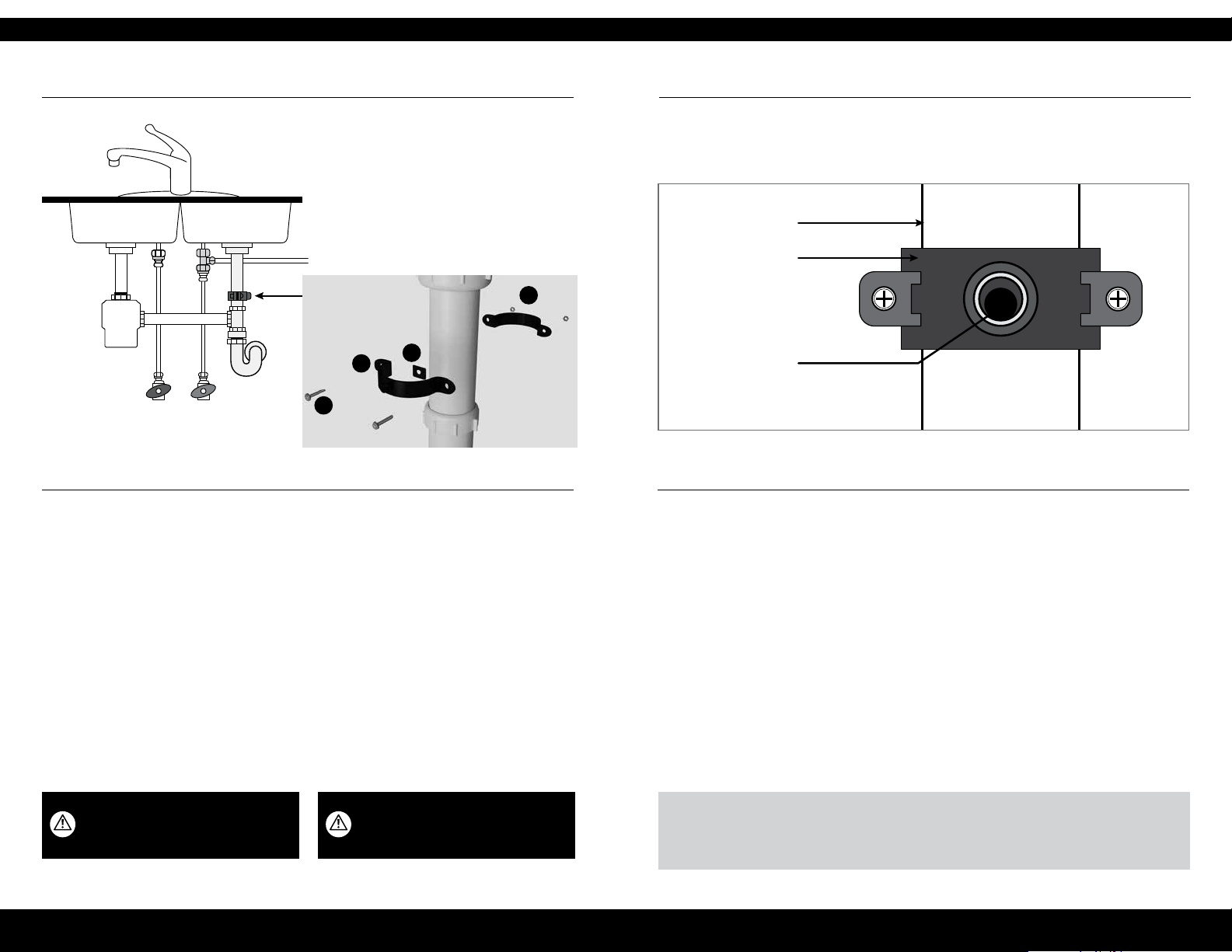
GUÍA DE INSTALACIÓN
PASO 5: Instalación del conector de drenaje
2524
TUBERÍA DE DRENAJE
SOPORTE
M
CALIENTE FRÍA
1 Identique la ubicación de la salida
de drenaje. No instale el conector de
drenaje en la misma tubería de drenaje
que el triturador de desperdicios de
comida. Si la tubería de drenaje se
debe instalar en la misma tubería
que el triturador de desperdicios de
comida, no use el conector de drenaje
que se incluye. Se recomienda el
conector del triturador de
desperdicios de comida.
L
M
N
2 Retire la cubierta protectora
de la parte posterior del sello
de espuma (N).
3 Abra el oricio central, alinee
los oricios e instálelo en la placa
delantera del conector de drenaje (L).
ORIFICIO NUEVO
4 Use el conector de drenaje para marcar
la ubicación de perforación en la
tubería de drenaje. Perfore un oricio
de 6mm (7/32") en la tubería de
drenaje. No penetre el lado opuesto de
la tubería.
5 Coloque el conector de drenaje en
la tubería de drenaje del fregadero,
sobre el sifón de drenaje, y deje
espacio para perforar.
6 Apriete rmemente las tuercas (M)
y los tornillos (M).
ADVERTENCIA Asegúrese de que todos los
artefactos eléctricos y tomacorrientes estén
apagados desde el disyuntor antes de realizar
trabajos en el área del gabinete.
PRECAUCIÓN Use gafas de seguridad para
proteger sus ojos mientras perfora.
CONSEJO PROFESIONAL
Si hay una fuga desde el soporte de drenaje, suelte los pernos y deslice el soporte hacia arriba, de modo que el
oricio perforado quede abajo del puerto del conector de drenaje.
Page 16
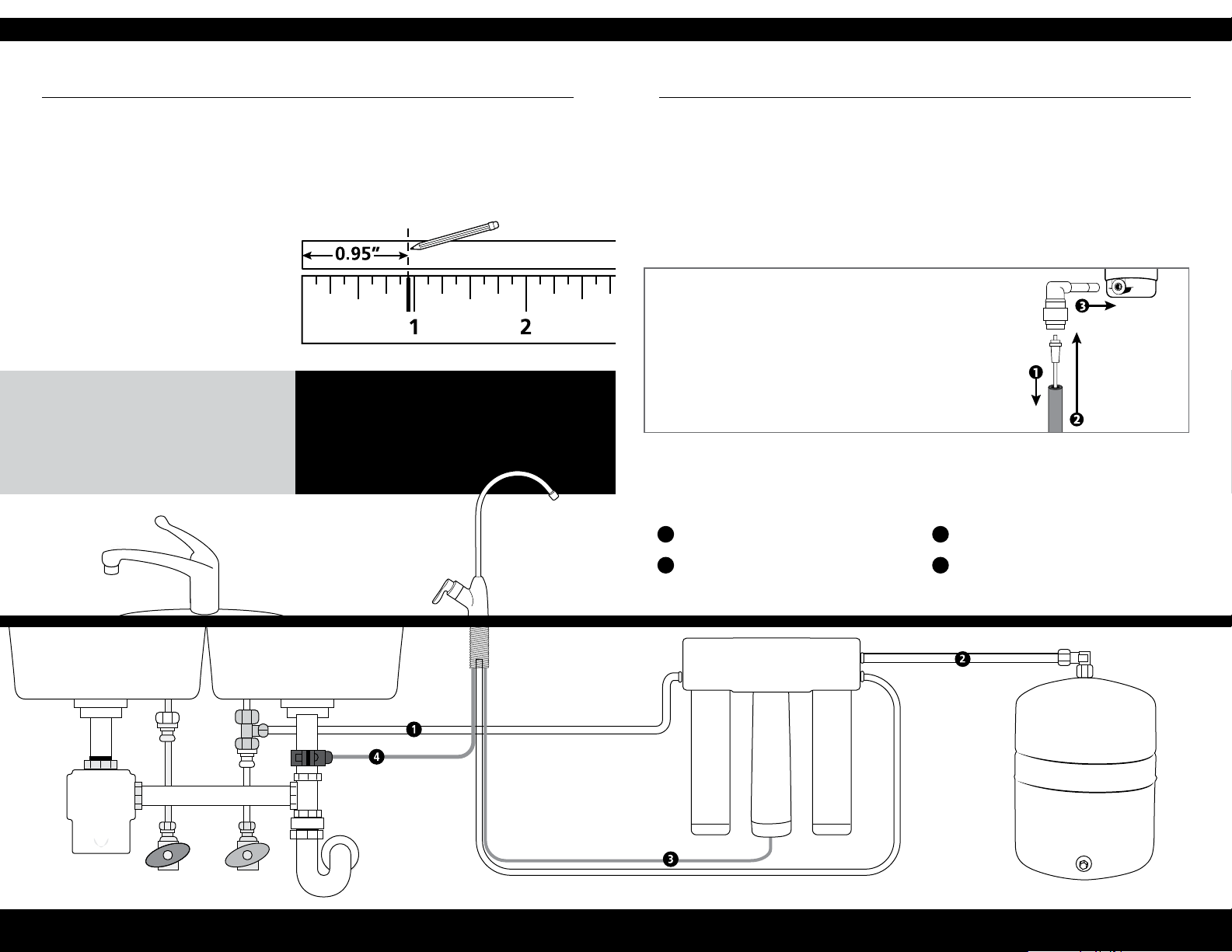
GUÍA DE INSTALACIÓN
PASO 6: Conexión de los tubos
2726
1 T de latón a “INLET” del colector
(tubo blanco de 1/4")
Tome el tubo blanco que va desde la
T de latón e insértelo en el puerto del
colector etiquetado “INLET” (Entrada).
Introduzca el tubo por completo hasta
que se detenga.
HAGA LO SIGUIENTE...
Inserte los tubos por completo (24.1mm [0.95"])
para evitar ltraciones.
Humedezca el extremo de los tubos para instalar
fácilmente en las entradas y salidas.
Corte el exceso de los tubos para evitar grietas,
torceduras, curvas o pliegues.
2 Conector a la llave
(tubo blanco de 3/8" ya conectado a la llave)
Inserte el tubo blanco de 3/8" (del PASO
3: Instalación de la llave de osmosis
inversa) desde la llave al puerto del
Colector etiquetado “FAUCET” (Llave).
Profundidad para insertar los tubos
El diagrama tiene la dimensión real.
NO HAGA LO SIGUIENTE....
Cortar los tubos demasiado cortos. Siempre
compruebe la medición antes de cortar.
Doblar, plegar o torcer los tubos.
Desechar el exceso de tubo.
3 Colector al tanque
(tubo blanco de 3/8" ya conectado al tanque)
Tome el tubo blanco de 3/8" que
sale del tanque de almacenamiento
e insértelo en el puerto del colector
5 Llave al conector de drenaje
(tubo rojo de 3/8" desde la llave)
Tome el tubo rojo de 3/8" desde la
llave e insértelo completamente en el
conector de drenaje.
etiquetado “Tank” (Tanque).
Introduzca el tubo por completo
hasta que se detenga.
4 Entrehierro a la membrana de osmosis inversa
(tubo rojo de 1/4" desde la llave)
1. Inserte el limitador en el extremo del tubo rojo.
2. Conecte el tubo rojo de 1/4" al codo en 90° hasta
que se detenga.
3. Conecte el codo en 90° de 1/4" al puerto de drenaje
de la membrana.
Conexiones de mangueras
BLANCA DE 1/4", T DE LATÓN AL
1
COLECTOR
BLANCA DE 3/8", COLECTOR
2
AL TANQUE
ROJA DE 1/4", MEMBRANA A
3
LA LLAVE
ROJA DE 3/8", LLAVE AL CONECTOR
4
DE DRENAJE
ADVERTENCIA:
La llave tendrá
fugas si no
se instala el
limitador.
CALIENTE
FRÍA
Page 17
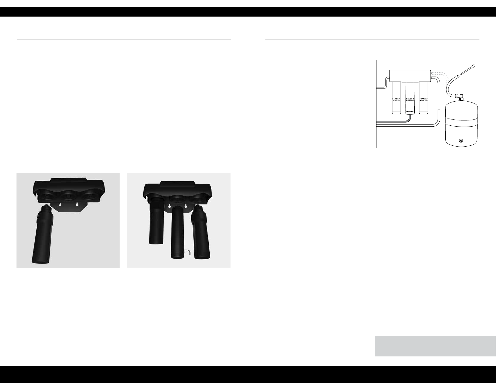
28 29
GUÍA DE INSTALACIÓN
PASO 7: Instalación del ltro
Antes de comenzar: Asegúrese de que la válvula de agua fría esté cerrada y que
no haya presión en el sistema. Los cartuchos de los ltros Claryum
con malla azul) y de carbón (tapas verdes con malla transparente) vienen instalados
previamente en los sumideros del cartucho.
1 Instale el sumidero de carbón en la
posición de primera etapa en el lado
de entrada del colector del sistema.
Asegúrese de que todos los puntos de
conexión estén alineados y empuje
la parte superior del sumidero hacia
arriba dentro del colector del sistema.
Gire el sumidero hacia la derecha hasta
que se bloquee.
2 Repita el paso 1 para la membrana de
osmosis inversa de segunda etapa que
encaja en el centro, y para el cartucho
de Claryum
etapa en el lado de salida del colector
del sistema.
®
(tapas verdes
®
en la posición de tercera
PASO 8: Desinfección, prueba y purga
Desinfección
1 Desconecte el tubo blanco de la salida
del colector etiquetada “Tank”.
2 Agregue 3ml de blanqueador
doméstico (5.25%) en el extremo
desconectado del tubo blanco con el
gotero (se incluye).
Nota: Manipule el blanqueador de
acuerdo con las instrucciones del
fabricante.
3 Use el tubo blanco para volver a
conectar el tanque en la salida del
colector etiquetada “Tank”. Introduzca
completamente el tubo.
4 La desinfección se completará durante
la siguiente prueba de presión y
purga. Importante: Se debe retirar
completamente el blanqueador
del sistema antes de beber agua.
Consulte las instrucciones de purga a
continuación.
Nota: Se recomienda desinfectar
inmediatamente después de la
instalación del sistema de ltro de OI y
después del mantenimiento de cualquier
pieza interna. La persona que desinfecte
debe tener las manos limpias durante
este proceso.
IMPORTANTE: Complete la desinfección antes de la
prueba de presión.
Page 18
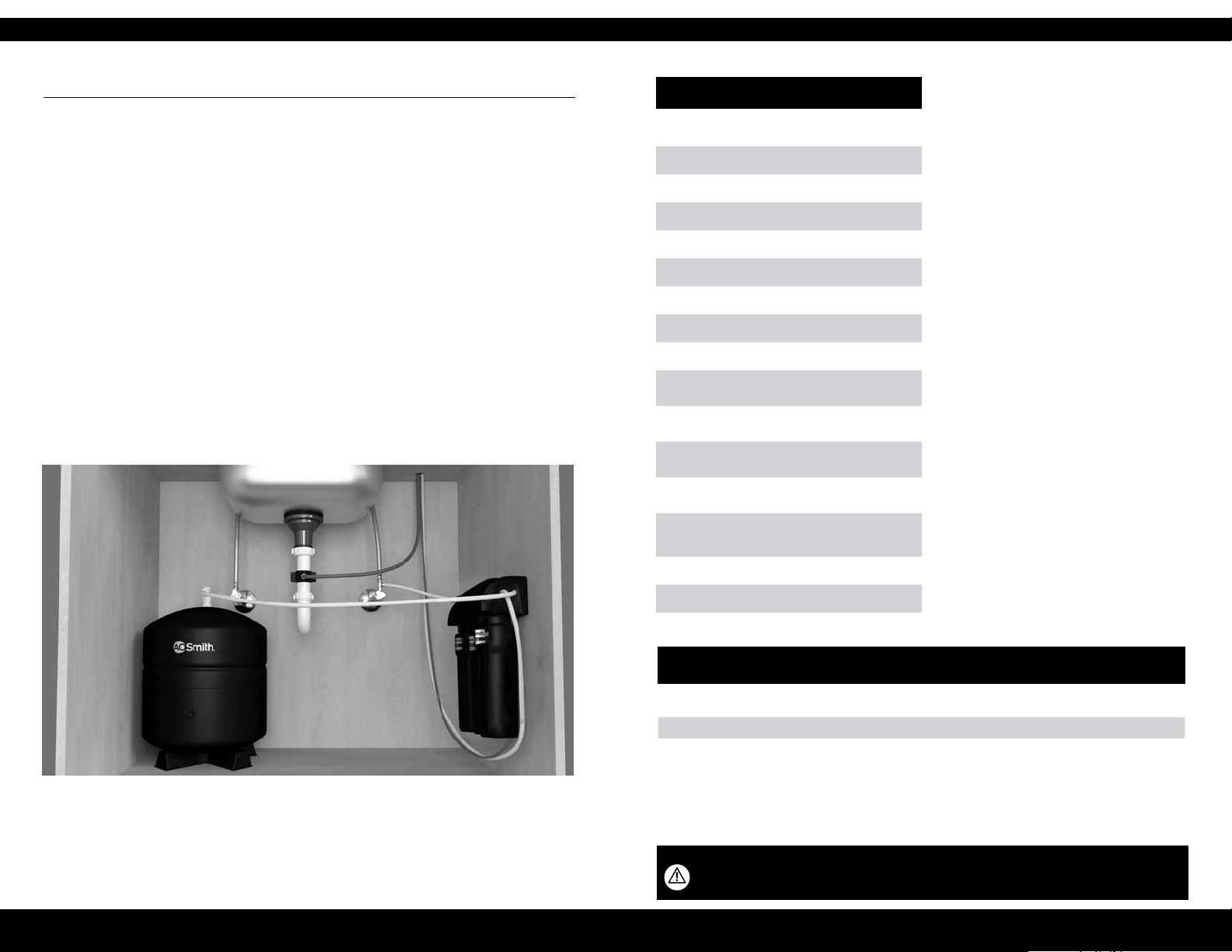
GUÍA DE INSTALACIÓN
CUIDADO Y MANTENIMIENTO
3130
PASO 8 - Desinfección, prueba y purga
Prueba de presión
1 Abra la válvula de suministro de agua
fría hacia el sistema del ltro de OI.
2 Abra la llave de la cocina para purgar
el aire del sistema. Cierre cuando el
agua uya de manera homogénea.
3 Conrme que la llave de OI esté
cerrada.
4 Dentro de aproximadamente 2 horas,
se comenzará a acumular presión en el
sistema del ltro de OI. Con cuidado,
inspeccione todas las conexiones y
conectores mientras se acumula la
presión.
Nota: Cuando se presuriza por primera vez
el sistema del ltro de OI, es posible que
el agua se proyecte desde el oricio de
entrehierro de la llave hasta que el aire pase
del sistema del ltro de OI.
5 Revise si hay fugas. Si encuentra fugas,
asegúrese de que todos los tubos
estén cortados rectos y que estén
completamente insertados. Conrme
que no haya rayas, abolladuras o
muescas en el extremo de los tubos. De
ser así, corte recto 25mm (1") del tubo
y vuelva a insertarlo.
Purga
1 Abra la llave de OI y permita que el
agua uya por el sistema por 24 horas.
Nota: El caudal será bajo en este
momento.
2 Cierre la llave de OI después de
nalizar la purga.
AOW-3000
Cartucho de repuesto AO-4000-CARBON y
AO-RO-RM-R
1
Producción de la membrana
Reducción de TDS de la membrana
Producción del sistema
Reducción de TDS
2
132lpd (35gpd)
1
2
50.4lpd (13.32gpd)
96.3%+ promedio
95% mínimo
TDS máx. 1000ppm
Dureza máx. del agua a pH6.9 2.64gpL (10gpg)
Máx. de cloro en el agua 3.0ppm
Límites de pH del agua de suministro 4 a 10
Flujo de drenaje (agua de rechazo) 3 a 5 veces el
ujo de producto
Precarga del tanque de almacenamiento vacío
35 a 48kPa de aire (5 a 7psi)
Capacidad del tanque de almacenamiento
2
12.11litros (3.2 galones)
Límites de presión del agua de suministro
275 a 689kPa (40 a 100psi)
Límites de temperatura del agua de suministro
5 a 37°C (40 a 100°F)
Eciencia3 17.91%
Recuperación
4
29.43%
Especicaciones: Rendimiento calicado
del sistema
Ya que el rendimiento de la membrana de
osmosis inversa depende mucho de la presión,
la temperatura y los sólidos totales disueltos
(TDS), lo siguiente se debe usar solo con nes
de comparación.
Las normas de la industria miden el
rendimiento de las membranas de osmosis
inversa sin contrapresión en el agua de
producto a 414 kPa (60psig) y 25°C (77°F).
Más condiciones acerca de lo anterior son TDS
de 250ppm y una velocidad de recuperación
de 30.6%. Las cifras de velocidad de producción
y reducción de TDS son para una membrana
nueva que se ha enjuagado durante 24 horas.
La velocidad de producción de una membrana
nueva puede disminuir en 10% o más por año,
según las tendencias de producción de sarro e
incrustaciones del agua de alimentación.
Medido a 345kPa (50psi), 25° ±1°C (77°± 2°F)
y 717mg/L de TDS según la norma NSF/ANSI 58.
La clasicación de eciencia es el porcentaje de
agua entrante al sistema que está disponible
para el usuario como agua tratada por osmosis
inversa. Esta medición se realiza en condiciones
de funcionamiento que se aproximan a un uso
diario típico.
La clasicación de recuperación es el porcentaje
de agua entrante a la parte de la membrana
del sistema que está disponible para el usuario
como agua tratada por osmosis inversa cuando
el sistema se hace funcionar sin un tanque de
almacenamiento o cuando este se omite.
Nota: El sistema de ltro de OI está listo para usar cuando se naliza la purga; sin embargo,
no tendrá agua ltrada inmediatamente. El llenado completo del tanque tardará entre 1
y 3 horas. El caudal será menor que en la llave de la cocina. El agua uirá hacia el drenaje
mientras el sistema del ltro de OI esté ltrando el agua, incluso cuando no esté en uso.
Esto es normal. El agua que va hacia el drenaje se detendrá automáticamente cuando el
tanque esté lleno.
CAPACIDAD EN DISTINTOS NIVELES DE PRESIÓN DE AGUA (CON PRECARGA DE 34KPA [5PSI])
LITROS (GALONES DE EE.UU.)
VOLUMEN TOTAL 138KPA
12.1 (3.2) 5.3 (1.4) 6.8 (1.8) 7.6 (2.0) 8.3 (2.2) 9.1 (2.4) 9.5 (2.5)
FUENTES DE AGUA NO POTABLE: No intente usar este producto para hacer que agua de fuentes no potables sea apta para el
consumo humano. No use el sistema en agua que no sea microbiológicamente segura o en agua de calidad desconocida sin la
desinfección adecuada antes o después del sistema. Este sistema está certicado para la reducción de quistes y se puede usar en
aguas desinfectadas que puedan tener quistes ltrables.
INSTALACIONES EN EL ESTADO DE MASSACHUSETTS: El Estado de Massachusetts exige que la instalación la realice un
plomero con licencia y no permite el uso de válvulas de silla. Se debe cumplir con el Código de plomería 248—CMR del Estado
de Massachusetts en estos casos.
No usar con agua que no sea microbiológicamente segura o cuya calidad sea desconocida sin la desinfección previa o posterior adecuada del
sistema. Es posible usar sistemas certicados para la reducción de quistes en aguas desinfectadas que puedan tener quistes ltrables.
El ltro solo se debe usar con agua fría. Es posible usar sistemas certicados para la reducción de quistes en agua desinfectada que pueda tener
quistes ltrables.
(20PSI)
207KPA
(30PSI)
276KPA
(40PSI)
345KPA
(50PSI)
414KPA
(60PSI)
483KPA
(70PSI)
Page 19

CUIDADO Y MANTENIMIENTO
3332
Kit de prueba de nitrato y nitrito:
Este sistema es aceptable para el
tratamiento de una concentración
entrante no mayor que 27mg/L
de nitrato y 3mg/L de nitrito, en
combinación medidos como N.* Este
sistema incluye un kit de prueba de
nitrato y nitrito. Se debe monitorear
periódicamente el agua del producto
de acuerdo con las instrucciones
proporcionadas con el kit de prueba.
Limitador de ujo de drenaje
El limitador es fundamental para el
funcionamiento correcto del Cartucho
de la membrana de osmosis inversa, ya
que mantiene el ujo de agua a través
de la membrana a la velocidad adecuada,
garantizando así que el agua producida
sea de la mejor calidad. Se recomienda
inspeccionar periódicamente el conjunto
de limitador para asegurarse de que
esté limpio y sin restricciones. Si se debe
realizar mantenimiento en el conjunto
de ujo de drenaje, desmonte y vuelva
a montar como se describe en el paso
cinco.
El caudal y la salida se determinan
mediante 3 factores:
1 Temperatura del agua entrante
2 Sólidos disueltos totales (TDS)
presentes en el agua de suministro
3 Presión del agua entrante
Las temperaturas más bajas son
directamente proporcionales a un caudal
más bajo. Todas las membranas se
prueban a 25°C (77°F). La temperatura
del agua entrante no debe exceder los
38°C (100°F). El sistema de ltro de
OI tampoco se debe instalar en una
ubicación susceptible a congelación.
Mientras más TDS haya en el agua de
suministro, mayor será el tiempo de
ltración necesario. Los TDS entrantes
no deben exceder las 1000ppm. La
mayor presión de agua permite un mayor
caudal. La presión debe estar sobre
276kPa (40psi) para un funcionamiento
adecuado del sistema. Puede considerar
la instalación de una bomba de
permeado o una bomba de refuerzo si la
presión está bajo los 276kPa (40psi).
Preltro de carbón y posltro Claryum®:
Cambiar cada 6 meses*
Los cartuchos del ltro de carbón y
®
Claryum
son cartuchos de carbón
activado reemplazables ubicados en las
etapas 1 y 3. Se recomienda cambiar
estos cartuchos al menos cada 6 meses.
Es posible que deba reemplazar con
más frecuencia en caso de un alto
consumo de agua o un alto nivel de
sedimentos. El reemplazo oportuno de
estos cartuchos protegerá la membrana
de osmosis inversa contra altos niveles de
cloro o sedimentos. Ya que se acumulan
sedimentos en estos ltros, observará un
caudal de agua más lento.
Cartucho de la membrana de osmosis
inversa: Cambiar cada 12 meses*
La membrana de osmosis inversa se
ubica en la etapa 2. Esta membrana
reduce los sólidos disueltos y la materia
orgánica. La mayoría del agua tratada
municipalmente tiene un pH de 7.0 a
7.5; en este caso, debería reemplazar
la membrana de osmosis inversa cada
12 meses. La vida útil de la membrana
depende del pH y la dureza del agua de
suministro. El mayor pH causa fugas por
oricios diminutos y acorta la vida útil de
la membrana. Cuando la salida, la calidad
del agua y la velocidad de producción
disminuyen, es tiempo de reemplazar.
Remineralizador:
Cambiar cada 12 meses*
El remineralizador es de etapa 4. Está
diseñado para proporcionar cantidades
saludables de calcio, magnesio y
potasio para obtener un agua de sabor
sensacional.
*La vida útil del ltro depende del uso
de agua y la calidad del suministro de
agua.
Page 20
34
CUIDADO Y MANTENIMIENTO
Este sistema se ha probado para el tratamiento de agua que contiene arsénico
pentavalente (también conocido como As(V), As(+5) o arseniato) en concentraciones
de 0.30mg/L o menos. El sistema reduce el arsénico pentavalente, pero es posible
que no elimine otras formas de arsénico. Este sistema se debe usar en suministros de
agua que contengan un cloro libre detectable residual en la entrada del sistema o en
suministros de agua que se haya demostrado que contengan solo arsénico pentavalente.
El tratamiento con cloramina (cloro combinado) no es suciente para garantiza la
conversión completa del arsénico trivalente a arsénico pentavalente. Consulte la sección
Datos del arsénico de esta Hoja de datos de rendimiento
para obtener más información.
Datos del arsénico
35
El arsénico (abreviado As) se encuentra
naturalmente en algunas aguas de pozo.
El arsénico en el agua no tiene color
sabor ni olor. Se mide con una prueba
de laboratorio. Los servicios públicos
de agua deben realizar pruebas de
arsénico en su agua. Puede consultar los
resultados con la empresa de servicios
públicos de agua. Si tiene su propio
pozo, puede realizar pruebas en el
agua. El Departamento de Salud local
o el organismo de salud ambiental
estatal pueden proporcionar una lista
de laboratorios certicados. El costo
generalmente es entre UDS15 y USD30.
La información acerca del arsénico en el
agua se puede encontrar en el sitio web
de la Agencia de Protección Ambiental de
EE.UU.: epa.gov/safewater/arsenic
Hay dos formas de arsénico: arsénico
pentavalente (As(V), As(+5) y arseniato)
y arsénico trivalente (también
llamado As(III), As(+3) y arsenito).
En agua de pozo, el arsénico puede
ser pentavalente, trivalente o una
combinación de ambos. Se necesitan
procedimientos de toma de muestras
para que un laboratorio determine
qué tipo y cuánto de cada tipo de
arsénico hay en el agua. Consulte con
los laboratorios de su área para ver si
ellos pueden proporcionar este tipo de
servicio.
Los sistemas de tratamiento de agua
de osmosis inversa (OI) no eliminan
completamente el arsénico trivalente
del agua. Los sistemas de OI son muy
ecaces en la eliminación del arsénico
pentavalente. Un cloro libre residual
convertirá rápidamente el arsénico
trivalente en arsénico pentavalente.
Otros tratamientos químicos de agua,
como ozono y permanganato de
potasio, también cambiarán el arsénico
trivalente a arsénico pentavalente. Es
posible que una combinación de cloro
residual (también llamada cloramina) no
convierta todo el arsénico trivalente. Si
obtiene el agua de un servicio público
de agua, comuníquese con la empresa
de servicios públicos para saber si se
usa cloro libre o cloro combinado en
el sistema de agua. El sistema AO-USRO-4000 está diseñado para eliminar
arsénico pentavalente. No convertirá
el arsénico trivalente en arsénico
pentavalente. Este sistema se probó
en un laboratorio. En condiciones de
• La clasicación de eciencia es el
porcentaje de agua entrante al sistema
que está disponible para el usuario
como agua tratada por osmosis inversa
en condiciones de funcionamiento que
se aproximan al uso típico diario.
prueba, el sistema redujo [0.30mg/L
(ppm) o 0.050mg/L (ppm)] de arsénico
pentavalente a 0.010mg/L (ppm) (la
norma de USEPA para el agua potable)
o menos. El rendimiento del sistema
puede ser distinto con su instalación.
Solicite la realización de pruebas de
arsénico en su agua tratada para revisar
si el sistema funciona correctamente.
El componente de OI del sistema
AO-US-RO-4000 se debe reemplazar
cada 1 a 3 años para garantizar que
el sistema siga eliminando el arsénico
pentavalente. La identicación de los
componentes y los lugares donde puede
comprarlos se indican en el manual de
instalación y operación.
• La clasicación de recuperación es el
porcentaje de agua entrante a la parte
de la membrana del sistema que está
disponible para el usuario como agua
tratada por osmosis inversa cuando
el sistema se hace funcionar sin un
tanque de almacenamiento o cuando
este se omite.
Page 21
36
Datos de rendimiento para el sistema para agua potable AO-US-RO-4000
Modelos Repuesto Rango de
AO-US-
AO-4000-CARBON
RO-4000
y AO-RO-RM-R
Fabricado por: A.O. Smith Corporation 11270 West Park Place | Milwaukee, WI 53224
Pruebas realizadas conforme a las normas NSF/ANSI 42, 53, 58, 401 y P473 y según el Programa de Dispositivos de Tratamiento de Agua Potable del Departamento de Servicios de Salud
de California. Este sistema se probó conforme a las normas NSF/ANSI 42, 53, 401 y P473 para la reducción de las sustancias que se indican más adelante. Se redujo la concentración de las
sustancias indicadas en el agua que entra al sistema a una concentración menor que o igual al límite permitido para el agua que sale del sistema, según se especica en las normas
NSF/ANSI 42, 53, 58, 401 y P473.
NSF/ANSI 42 Reducción mínima
Chlorine Reduction, Free Available
Chloramine Reduction, Free Available
Particulate Reduction 85% 99.9% Aprobado
NSF/ANSI 53 Reducción mínima
Cyst Live Cryptosporidium & Giardia 99.95% >99.99% Aprobado
Mercury Reduction pH 8.5 <2 ug/L >95.8% Aprobado
Mercury Reduction pH 6.5 <2 ug/L >96.5% Aprobado
Lead Reduction pH 6.5 <10 ug/L >99.4% Aprobado
Lead Reduction pH 8.5 <10 ug/L >99.3% Aprobado
MTBE Reduction <5 ug/L 86.6% Aprobado
Turbidity <0.5 NTU 99.1% Aprobado
VOC Surrogate Test 95% 99.4% Aprobado
Asbestos 99% >99% Aprobado
NSF/ANSI 58
Arsenic Pentavalent 0.30mg/L ± 10% 80.0% 97.6% Aprobado
Barium 10.0mg/L ± 10% 80.0% 95.2% Aprobado
Cadmium 0.30mg/L ± 10% 83.3% 95.3% Aprobado
Chromium Hexavalent 0.30mg/L ± 10% 66.7% 97.0% Aprobado
Chromium Trivalent 0.30mg/L ± 10% 66.7% 96.6% Aprobado
Copper 0.30mg/L ± 10% 56.7% 96.6% Aprobado
Fluoride 8.0mg/L ± 10% 81.2% 95.7% Aprobado
Lead .15mg/L ± 10% 93.3% 96.6% Aprobado
Nitrate/Nitrite 30.0mg/L ± 10% 66.7% 82.4% Aprobado
Radium 226/228 25pCi/L ± 10% 80.0% 80.0% Aprobado
Selenium 0.10mg/L ± 10% 50.0% 97.9% Aprobado
TDS 750mg/L ± 10% 75.0% 95.0% Aprobado
Turbidity 11 ± NTU 95.4% 99.1% Aprobado
NSF/ANSI 42
Atenolol 30 ng/L 94.2% 94.2% Aprobado
Bisphenol A 300 ng/L 98.80% 98.9% Aprobado
Carbamazepine 200 ng/L 98.6% 98.6% Aprobado
DEET 200 ng/L 98.7% 98.7% Aprobado
Estrone 20 ng/L 96.30% 96.5% Aprobado
Ibuprofen 60 ng/L 95.3% 95.4% Aprobado
Linuron 20 ng/L 96.6% 96.6% Aprobado
Meprobamate 60 ng/L 94.7% 94.7% Aprobado
Metolachlor 200 ng/L 98.6% 98.6% Aprobado
Naproxen 20 ng/L 96.3% 96.4% Aprobado
Nonyl phenol 200 ng/L 97.50% 97.5% Aprobado
Phenytoin 30 ng/L 95.50% 95.6% Aprobado
TCEP 700 ng/L 98% 98% Aprobado
TCPP 700 ng/L 97.8% 97.8% Aprobado
Trimethoprim 20 ng/L 96.7% 96.7% Aprobado
NSF P473
Peruorooctanoic acid
(PFOA) & Peruorooctane
sulfonate (PFOS)
• Se indican todos los contaminantes que reduce este ltro.
• Es posible que no todos los contaminantes indicados estén presentes en su agua.
• No elimina todos los contaminantes que pueden estar presentes en el agua de la llave.
Concentración
máxima
El ltro solo se debe usar con
agua fría.
El uso del ltro debe cumplir
con todas las leyes estatales y
locales.
Las pruebas se realizaron en
condiciones de laboratorio estándar,
el rendimiento real puede variar.
presión de
funcionamiento
275 a 689kPa
40 a 100psi
<0.5 mg/l 97.66% Aprobado
<0.5 mg/l 97.66% Aprobado
Concentración
máxima
Reducción mínima
Concentración de
riesgo de ingreso
1.5 ±10% ug/L 0.07 ug/L 96% Aprobado
Rango de
temp. de
funcionamiento
4.44 a 32.2°C
40 a 90°F
Porcentaje total de
reducción
Porcentaje total de
reducción
Reducción
mínima
Porcentaje total de
reducción
Porcentaje total de
reducción
Concentración
máxima permitida
Es posible usar sistemas certicados
para la reducción de quistes en
aguas desinfectadas que puedan
tener quistes ltrables.
Consulte el manual del propietario
para conocer las condiciones y
necesidades generales de instalación
más la garantía limitada del
fabricante.
Clasicación
Clasicación
de
de eciencia
recuperación
29.43% 17.91% 50.4litros
Resultados
Resultados
Resultados
Resultados
Porcentaje
total de
reducción
Resultados
Producción diaria
(DPR)
13.32galones
Productos químicos orgánicos incluidos por la prueba de sustitutos
COV (según la prueba de
sustitutos con el uso de
cloroformo)
alachlor 0.002 0.050 0.001 >98%
atrazine 0.003 0.100 0.003 >97%
benzene 0.005 0.081 0.001 >99%
carbofuran 0.04 0.190 0.001 >99%
carbon tetrachloride 0.005 0.078 0.0018 98%
chlorobenzene 0.1 0.077 0.001 >99%
chloropicrin — 0.015 0.0002 99%
2,4-D 0.07 0.110 0.0017 98%
dibromochloropropane (DBCP) 0.0002 0.052 0.00002 >99%
o-dichlorobenzene 0.6 0.080 0.001 >99%
p-dichlorobenzene 0.075 0.040 0.001 >98%
1,2-dichloroethane 0.005 0.088 0.0048 95%
1,1-dichloroethylene 0.007 0.083 0.001 >99%
cis-1,2-dichloroethylene 0.07 0.170 0.0005 >99%
trans-1,2-dichloroethylene 0.1 0.086 0.001 >99%
1,2-dichloropropane 0.005 0.080 0.001 >99%
cis-1,3-dichloropropylene — 0.079 0.001 >99%
dinoseb 0.007 0.170 0.0002 99%
endrin 0.002 0.053 0.00059 99%
ethylbenzene 0.7 0.088 0.001 >99%
ethylene dibromide (EDB) 0.00005 0.044 0.00002 >99%
haloacetonitriles (HAN)
bromochloroacetontrile — 0.022 0.0005 98%
dibromoacetontrile — 0.024 0.0006 98%
dichloroacetontrile — 0.0096 0.0002 98%
trichloroacetontrile — 0.015 0.0003 98%
haloketones (HK)
1,1-dichloro-2-propanone — 0.0072 0.0001 99%
1,1,1-trichloro-2-propanone — 0.0082 0.0003 96%
heptachlor (H-34, Heptox) 0.0004 0.025 0.00001 >99%
heptachlor epoxide 0.0002 0.0107 0.0002 98%
hexachlorobutadiene — 0.044 0.001 >98%
hexachlorocyclopentadiene 0.05 0.060 0.000002 >99%
lindane 0.0002 0.055 0.00001 >99%
methoxychlor 0.04 0.050 0.0001 >99%
pentachlorophenol 0.001 0.096 0.001 >99%
simazine 0.004 0.120 0.004 >97%
styrene 0.1 0.150 0.0005 >99%
1,1,2,2-tetrachloroethane — 0.081 0.001 >99%
tetrachloroethylene 0.005 0.081 0.001 >99%
toluene 1 0.078 0.001 >99%
2,4,5-TP (silvex) 0.05 0.270 0.0016 99%
tribromoacetic acid — 0.042 0.001 >98%
1,2,4-trichlorobenzene 0.07 0.160 0.0005 >99%
1,1,1-trichloroethane 0.2 0.084 0.0046 95%
1,1,2-trichloroethane 0.005 0.150 0.0005 >99%
trichloroethylene 0.005 0.180 0.0010 >99%
trihalomethanes (THMs)
bromodichloromethane (THM)
bromoform (THM)
chloroform (THM)
chlorodibromomethane (THM)
xylenes (total) 10 0.070 0.001 >99%
Sistema probado y certicado por NSF International según
las normas NSF/ANSI 42, 53, 58 y 401, y conforme al
protocolo P473 de NSF para la reducción de las declaraciones
especicadas en la Hoja de datos de rendimiento y en www.
COMPONENT
nsf.org.
Solo para uso con agua tratada localmente. No usar con agua que
no sea microbiológicamente segura o cuya calidad sea desconocida
sin la desinfección previa o posterior adecuada del sistema.
Nivel
normativo de
agua potable
(NMC/CMA)
mg/L
0.080 0.300 0.015 95%
Entrante/
Sin ltrar
Inuent/
Unltered
Saliente/
Filtrada
Efuent/
Filtered
Porcentaje
de
reducción
Percent
Reduction
GARANTÍA LIMITADA
2
AÑOS
Lo que está cubierto:
Esta garantía cubre defectos en
materiales o en la mano de obra de la
fabricación de sus sistemas de ltrado
de agua potable de A. O. Smith, salvo
según se estipula a continuación.
Duración:
Esta garantía dura dos años a partir
de la fecha de compra por parte del
consumidor (“Período de garantía”).
Lo que no está cubierto:
Esta garantía no cubre cartuchos
de ltro y ningún producto que se
haya instalado sin cumplir con las
instrucciones o que se haya abusado
u operado de manera incorrecta. La
garantía limitada que se indica en
este documento reemplaza cualquiera
y todas las garantías, expresas o
implícitas, ya sea por escrito o en
forma oral, lo que incluye, entre otras,
las garantías implícitas de idoneidad
para un propósito en particular o la
garantía implícita de comerciabilidad.
A. O. Smith no será responsable por
ningún daño indirecto, emergente,
especial o contingente que surja directa
o indirectamente de cualquier defecto
o uso del sistema. El propietario será
responsable por toda la mano de obra
y cualquier otro gasto relacionado con
el retiro, reparación o instalación del
sistema de ltración o de cualquier
pieza componente. Por último, se
anulará esta garantía si el producto se
usa con piezas que no sean originales
de A. O. Smith. Esto incluye, entre
otros, ltros de repuesto, llaves y
válvulas de cambio.
A. O. Smith Corporation P.O. Box 1597 | Johnson City, TN 37605-1597
37
Lo que A. O. Smith hará:
Reemplazaremos la pieza defectuosa
del producto cubierto y se la
enviaremos después del pago de USD
9.50 por el envío y manipulación por
incidente.
Cómo obtener el servicio: Para recibir
el servicio conforme a esta garantía,
debe comunicarse con A. O. Smith
por correo electrónico a
[email protected]
dentro del Período de garantía
y describir el problema a un
representante de servicio al cliente,
el que vericará que el producto esté
cubierto por la garantía y programará
el envío de un repuesto.
Cómo se aplica la ley estatal:
Esta garantía otorga derechos
especícos, pero es posible que
tenga otros derechos que varían
según el estado.
Algunos estados no permiten la
exclusión o limitación de garantías
implícitas o de daños indirectos o
consecutivos, por lo que es posible
que la limitación anterior no le
corresponda.
Tarjeta de garantía:
No es necesario registrar la garantía
para la cobertura conforme a la
garantía limitada de A. O. Smith.
Si realizó la compra a través de un
minorista o distribuidor, complete
el registro de garantía en línea en
aosmithatLowes.com/register. Una
vez registrada en línea, tendremos un
registro de su compra y no tendrá que
presentar un comprobante de compra
por una reclamación de garantía.
Page 22
The recommended replacement frequency
for the AOW-3000 Filtration System is:
Carbon blocks / every 6 months or 365 gallons
Membrane / once a year
La frecuencia de reemplazo recomendada para
el sistema de ltración AOW-3000 es la siguiente:
Bloques de carbón / cada 6 meses o 1382L (365galones)
Membrana / una vez al año
Get the most out of your lter by using
only genuine A. O. Smith replacements.
Visit www.aosmith.com/wholesale
to nd replacements or call 833.232.9711
to speak to a Wholesale Reprentative.
Aproveche al máximo su ltro con los repuestos originales de A. O. Smith.
Visite www.aosmith.com/wholesale para encontrar repuestos o llame al
833.232.9711 para comunicarse con un representante de Venta al por mayor.
This lter System is designed and tested for use with genuine A. O. Smith parts, including replacement lters, faucet and all
hardware. Use of parts from other manufacturers may result in loss of contaminant reduction performance, System damage or
failure. Use of parts from other manufacturers will also void your warranty. Please visit AOSmithAtLowes.com for replacement
parts. Installation must comply with state and local ordinances.
A. O. Smith is not liable for consequential or incidental damages due to improper installation.
Este sistema de ltrado está diseñado y probado para ser usado con piezas originales de A. O. Smith, lo que incluye los ltros, la llave y todas las piezas
metálicas de repuesto. El uso de piezas de otros fabricantes puede generar una pérdida en el rendimiento de la reducción de contaminantes, dañar
el sistema o causar fallas. El uso de piezas de otros fabricantes también anulará su garantía. Visite AOSmithAtLowes.com para pedir repuestos. La
instalación debe cumplir con las ordenanzas estatales y locales.
A. O. Smith no se hace responsable por daños indirectos o emergentes a causa de una instalación incorrecta.
System Tes ted and Certie d by NSF Internatio nal against NSF/A NSI Standards
42, 53, 58 & 4 01 and conforms to NSF P rotocol P473 for the re duction of the
claims sp ecied on the Perf ormance Data She et and at www.ns f.org.
Sistema pr obado y certifica do por NSF Internati onal según las norma s NSF/ANSI 42, 53,
58 y 401, y conform e al protocolo P473 de NSF p ara la reducción de las d eclaraciones
especifi cadas en la Hoja de dato s de rendimiento y en ww w.nsf.org.
AOW-3000_install_20190319
A. O. Smith Corporation P.O. Box 1597 | Johnson City, TN 37605-1597 | 833.232.9711
 Loading...