

Page 1
Chapter of Contents
Chapter of Contents
Chapter of Contents................................................................................................1
1.1 A Thank-you Note Before You Get Started............................................... 3
1.2 The Features Of This Manual..................................................................4
1.3 Preliminary Tools......................................................................................5
Chapter 2 What’s In The Box?................................................................................6
2.1 What’s In The Box?..................................................................................6
2.2 Accessory.................................................................................................7
2.3 What Specification Do We Got here?.......................................................8
2.4 What Features bundled here?................................................................10
Chapter 3 Start To Assemble ................................................................................ 1 1
3.1 Features of XC cube.............................................................................. 11
3.2 Starting installing....................................................................................12
3.3 Cooler, Hard Disk, Floppy Drives and DVD-RW devices.......................12
3.3.1 Taking Cooler out........................................................................12
3.3.2 Install Hard disk..........................................................................15
3.3.3 Install Floppy Drive.....................................................................15
3.3.4 Install DVD-RW Drive.................................................................15
3.4 Cables and Connectors..........................................................................16
3.5 Install CPU, CPU Cooler and CPU Fan Connector...............................18
3.6 Connecting DRAM to DIMM Sockets.....................................................20
3.7 Insert AGP card or PCI card to motherboard.........................................21
3.8 Putting Drives Cage back to Chassis.....................................................22
3.9 All Set .....................................................................................................23
3.10 How about all external peripheral? ......................................................24
Chapter 4 Turn On The Power!.............................................................................28
1
Page 2
Chapter 5 Wonderful Feature Provided From AOpen...........................................32
Postscripts.............................................................................................................34
Appendix...............................................................................................................35
2
Page 3
1.1 A Thank-you Note Before You Get Started
First of all, we would like to express our gratitude for purchasing our
XCcube. Once again, this bare-system is designed uniquely to meet all your personal needs with our
great industry-designing ability and our everlasting perseverance to the quality of all our products.
This manual is for those who want to set up computer by themselves. In other words, this is a
book for " Fresh drivers on the road." If you are already a veteran, this manual may not be suitable for
you. It is our hope that novices can build up their own computer step by step.
Now, we would like to invite you to personally experience this user-friendly manual and all of the
powerful functions this
The logos of Adobe and Acrobat are the registered trademarks of Adobe Systems Incorporated.
The logos of AMD, Athlon, and Duron are the registered trademarks of Advanced Micro Devices, Inc.
The logos of Intel, Intel Celeron and Pentium II&III are the registered trademarks of Intel Corporation.
The logos of nVidia are the registered trademarks of nVidia Corporation.
The logos of Microsoft, Windows are the registered trademarks of Microsoft Corporation in America and other
countries.
All the titles of the products and the trademarks mentioned in this manual are for the purpose of illustrative
conveniences and are possessed by their respective firms.
We regret not informing about any changes in usage standards and other related information. AOpen Company
reserves the right of altering or modifying the conte nt of thi s manual . In ca se o f any mist a ke s or in correct de scripti ons,
which include those on the products, AOpen makes no guarantee or commitments.
This document is based on the copyright laws in order to protect our company and reserve all rights.
Under no circumstances are any types of duplicating and loading this brochure in any databases and media
permitted except the permission signed on formal document by AOpen Company.
1996-2003 Copyrights, AOpen Ltd. All rights reserved.
http://www.aopen.com
AOpen
XCcube offers.
specially-designed
AOpen
3
Page 4
1.2 The Features Of This Manual
In this manual, you'll be able to learn how to:
set up a personal computer on your own.
correctly and safely put everything together and learn something about
hardware.
learn some practical techniques that make doing the job easier.
In addition, this manual DOES NOT offer you:
any sorts of back doors, such as overclocking.
a great deal of hardware standard that are hard to comprehend.
lengthy fanciful article or vague theories.
Instead, this manual explains profound theories in simple language by colorful illustrations.
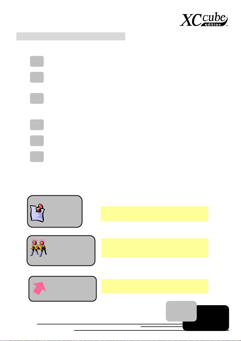
Therefore, you will see the icons below frequently:
Note mark
Warning mark
Force direction
Contains knowledge you should know in process of
assembling, or some helpful tips.
Please be careful when you see this mark. It highlights
mistakes that occur often during assembling, or
something you need to pay attention to.
This arrow shows the right direction the force should be
imposed, or the correct assembling direction.
4
Page 5
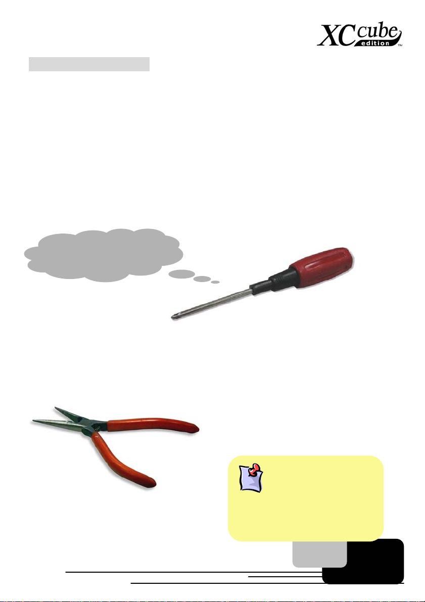
1.3 Preliminary Tools
"A workman must first sharpen his tools if he is to do his work well". Right before you start the
assembly, there are some tools that can't be spared.
Firstly, the most frequently-used too is cross screwdriver by which most interior components are
fixed. A suitable screwdriver can make the following job much easier. Being so, does any
screwdriver apply? Actually a magnetic tip one is suggested. That is because in the process of
setting up your PC, the situation is very likely to happen: you accidentally drop the screws into the
interior of the computer. In case of this, a magnetic screwdriver helps attracting the fallen screws that
are hard to reach by hands. Some scre w holes are placed where hands can hardly reach. At this
time, we need a magnetic screwdriver, too. In addition, the size of our tool also matters. Generally,
the
domestic 107 cross screwdriver
I can get it done!!
is the most appropriate one.
When putting things together, it is necessary to adjust Jumper. In most cases, things can be
done barehanded. But there comes a time always when your hands fail to reach in and fix the
problem. You'll thank God with a pliers on hand which keeps you away from any annoying trouble for
just setting one JUMPER.
What is Jumper?
Jumper is something generally referred to
" Jumping wire" that utilizes the short
circuit of the pins to tune up some
functions, such as FSB (front side bus),
ratio, and sound switches adjusting.
5
Page 6
Chapter 2 What’s In The Box?
Chapter 2 What’s In The Box?
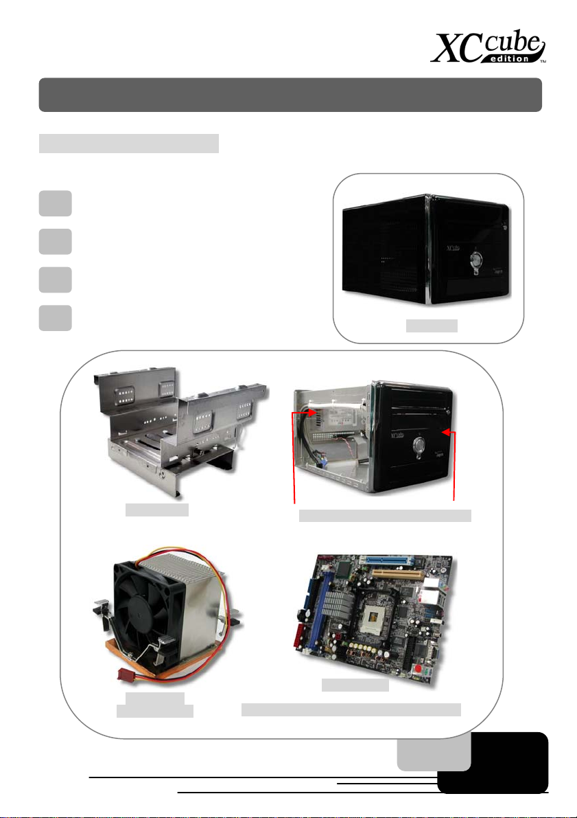
2.1 What’s In The Box?
Open the XCcube box, you will finds components as follow:
XCcube chassis / Drives Cage
CPU cooler
Motherboard
Power Supply
Drives Cage
All in One
Power Supply / XC cube chassis
CPU cooler
(EZ65 or EZ18)
[UX4SG-1394 (EZ65) / UK79G-1394 (EZ18)]
Motherboard
6
Page 7
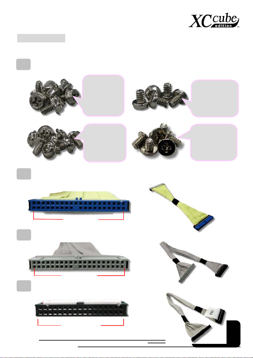
2.2 Accessory
Beside main components, you are supposed to see the following accessories:
Fixed screws:
screws:
IDE Cable:
IDE Cable:
Disk Drive Cable
After opening the accessory parcel, you'll see the following four different type of
As shown in the
picture, the
threads on
NO.1 screw are
wide and it has
a hexagonal
head
As shown in the
picture, threads
on NO.2 screw
are narrow and
there is a ring
on its head.
a 80 -pin connector to connect the hard disk with IDE interface.
80-wire hard disk
Connector
a 80 -pin connector to connect the DVD-RW IDE interface.
80-wire DVD-RW
Connector
: a 34-pin connector to connect disk drive.
As shown in the
picture, the NO.4
screw’s threads
are wide as well
but it has a flat
head.
As shown in the
picture, the NO.3
screw’s threads
are wide as well
but it has a round
head.
34-Pin Connector
7
Page 8
39
CPU
p
A
(ATA
X
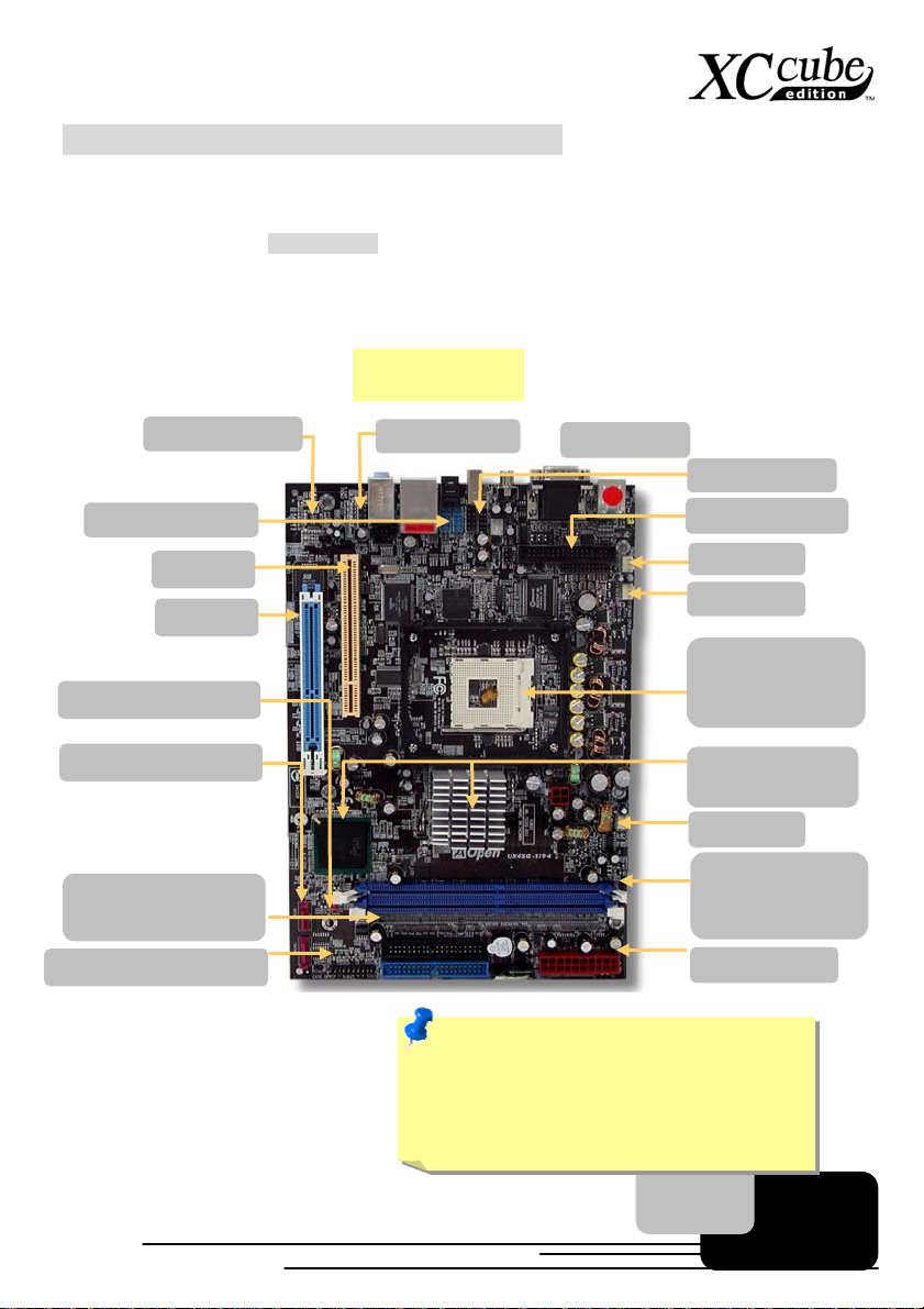
2.3 What Specification Do We Got here?
This XCcube comes with two type of motherboard for your selection. Let’s take a brief look at what
specification these two boards got.
For Intel lover, we provide UX4SG-1394 here.
Please refer to the Appendix chapter for motherboard details.
JP14 CMOS Jumper
AC’97 CODEC
USB Connectors
PCI slot
AGP 8X
X
U
4
S
G
-
1
3
9
X
U
4
S
U
4
S
44
G
-
1
3
9
G
-
1
3
9
4
Back Panel
IEEE1
FDD Connector
478-pin CPU
supports Intel®
Pentium® 4 CPU
4 x 2
FAN1
Serial ATA Ports X 2
IDE Connector x 2
33/66/100
Front Panel Co
nnector
Intel 865
Chi
set + ICH5
SYSFAN2
DDR400/333/266
DIMM x 2
Max. 2 GB
TX Power
Note: Intel 865G chipset don’t support
Willamette or Celeron (0.18u) processors.
Northwood processor would detect the clock
ratio automatically, you may not be able to
adjust the clock ratio in BIOS manually.
8
Page 9
o
A
y)
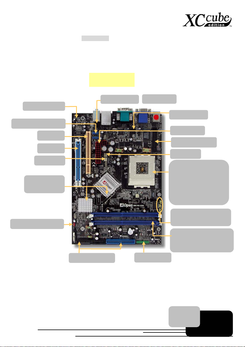
For Pro- AMD user, we provide UK79G-1394.
Please refer to the Appendix chapter for motherboard details.
AC’97 CODEC
USB connectors x 2
JP14 CMOS Jumper
PCI slot
AGP 8X
SYSFAN2
nForce2-GT
(IGP+ MCP-T)
U
K
7
U
K
7
U
K
7
IDE Connector
9
G
-
1
3
9
9
G
-
1
3
9
9
G
-
1
3
9
Front Audi
44
4
Back Panel
Front Panel
IEEE1394 x 2
TX Power
FDD Connector
SYSFAN3
462-pin CPU Socket
that supports AMD
Athlon / Duron / and
AthlonXP ( with CPU
Overheat Protection
circuit to AthlonXP
CPU onl
Dr.Voice II (JP15, J
& JP2
DDR400 (VGA Disabled)
/333/266 DIMM x 2
Max. 2 GB
P16)
9
Page 10
2.4 What Features bundled here?
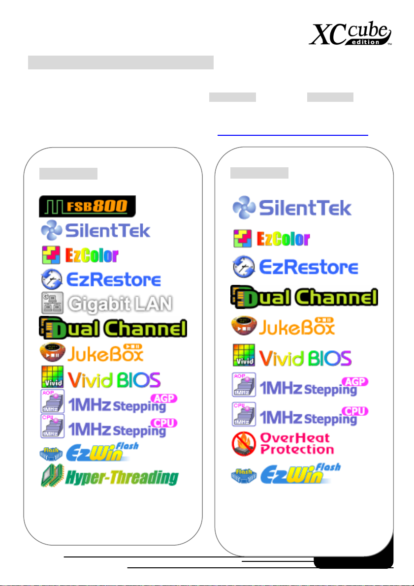
One of the advantages of AOpen motherboard is its inventive features, which bundled along with their
models. Various features had been included in UX4SG-1394 (EZ65) and UK79G-1394 (EZ18)
motherboard.
You may directly visit our technical website for details:
UX4SG-1394
http://english.aopen.com.tw/tech/techinside
UK79G-1394
10
Page 11
Chapter 3 Start To Assemble
Chapter 3 Start To Assemble
3.1 Features of XC cube
AOpen XC cube
may find that it is elegant among other traditional PC design that obviously highlighted your individual
style and taste with different color panel provided. In addition to it’s unique appearance, AOpen XC
cube is easy to move around in your house, suitable for decoration even in your living room. As light
and crispy as it is, it is definitely your choice for a PC.
Unique design that reflects your style and taste!
Color Panel changing that changes with your mood!
Space flexibility allows you to move it from living room or to your bedroom.
Silent Technology, PC that is quiet even in the middle of the night.
Easy Installation for any new hand assembling their first PC.
Mini housing which saves you almost 60% of housing space.
Hand-harmlessness design ensures you 100% security during assembling.
Equipped with a highly efficient power supply to keep your computer work
smoothly in most cases.
Conform to FCC ClassB/DoC and CE standards to guarantee your health.
Teamed with high-efficiency motherboard to make your job a great deal easier.
Great extensible function where you can optionally purchase AGP/PCI interfaces
with low-profile standards.
, designed as a Mini-PC, providing you as many advantages as it can. You
11 12
Page 12
3.2 Starting installing
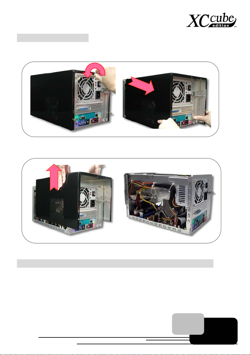
1. Unscrew all screws on the chassis. Use your thumb to push the chassis backward to you.
2. Lift the chassis up. Here you may see the internal of the chassis.
3.3 Cooler, Hard Disk, Floppy Drives and DVD-RW devices
3.3.1 Taking Cooler out
Before installing hard disk, floppy drives and DVD-RW into the XC cube chassis, let’s take the cooler
out from chassis first.
Page 13
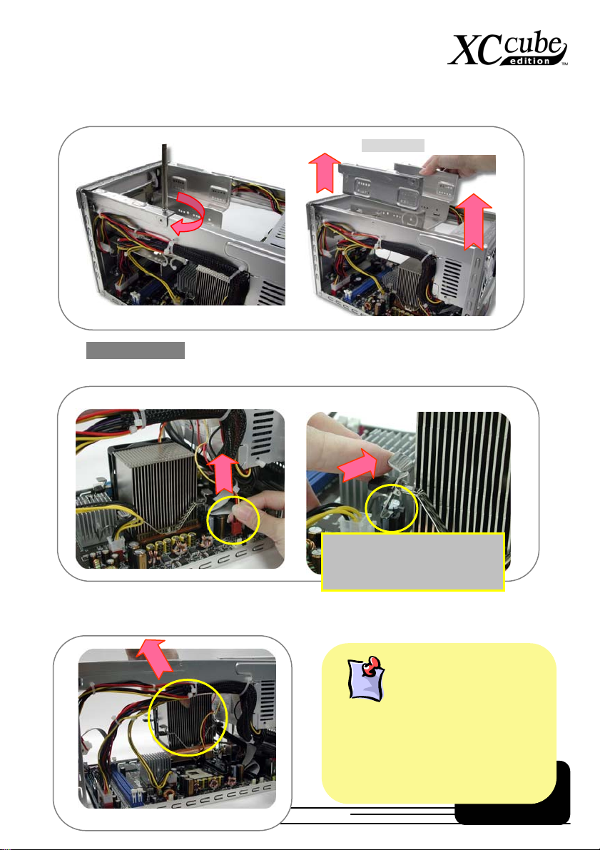
1. Take the screws off the chassis and then take the Drives Cage out.
2. For EZ65 XC cube PC,. Before taking AOpen-made Cooler out, please disconnect its connector
first. After that, unfasten AOpen-made Cooler.
Take the cooler out of the chassis. Put it aside for later use then.
Drives Cage
Pull the iron plate up and
relieve it from the hook of
retention module.
13
After thermal testing and confirmation, we
have chosen this model of AOpen cooler for
fitting with XC cube. It has been tested with
optimized air-flow and excellent heat
dissipation function for our XC cube system.
It is highly recommended
branded cooler to go with XC cube.
Why AOpen Fan Cooler?
to use other
not
Page 14

3. For EZ18 XC cube PC. Before taking AOpen-made Cooler out, please disconnect its connector
first. After that, unfasten AOpen-made Cooler.
The bottom of Cooler had been protected
with a plastic cover when shipped.
Please take it off when you want to put the
cooler on CPU.
It would be a lot of problem if we have had
installed the devices in the incorrect direction.
Therefore, please kindly pay attention to the
FRONT mark shown in the picture.
Where’s the direction?
Use a screwdriver to push
the iron lock down to relieve
it from the socket.
Take the cooler out of the chassis. Put it aside for later use then.
14
Page 15
3.3.2 Install Hard disk
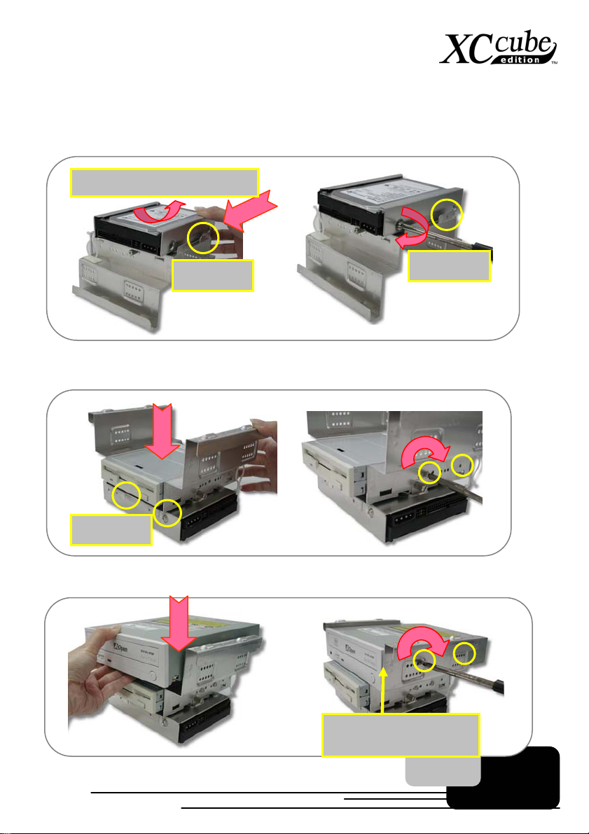
After taking out Cooler , let’ s focus on Inst alling Drives Cage. Slide hard disk into the Drives Cage,
and use screw no. 3 to screw it firmly to the cage.
Heat dissipation side face up.
Front mark
Front mark
3.3.3 Install Floppy Drive
1. Slide in the floppy drive as shown. Use screw no.2 to screw the 3rd and 6th hole separately.
Front Mark
3.3.4 Install DVD-RW Drive
1. Slide in the DVD-RW drive. Use screw no.2 to screw the DVD-RW firmly.
DVD-RW must aim at the
edge of Drives Cage.
15
Page 16
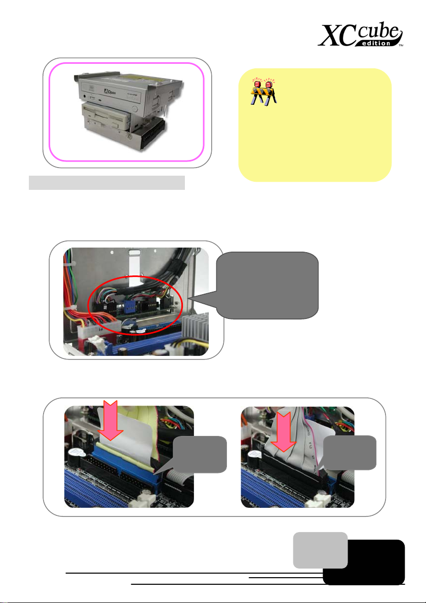
Don't mess up screws!!
Generally there are special screws for
hard disk in the parcel when you buy a
new hard disk. There will be no harm
done using those screws. If no screws
are attached, use those packed in the
accessory parcel. Make sure to use the
NO.2 screws. (See page 6)
3.4 Cables and Connectors
1. Before connecting necessary cables and connector to motherboard, you may found most of the
I/O panel connectors (IEEE1394, USB, Front Audio and S/PDIF) both at front panel and back
panel on motherboard have had been connected properly as shown.
I/O connectors have
had been inserted
previously.
2. Connecting floppy cable, hard disk and DVD-RW cable on motherboard for later use.
Hard disk
cable
DVD-RW
cable
16
Page 17
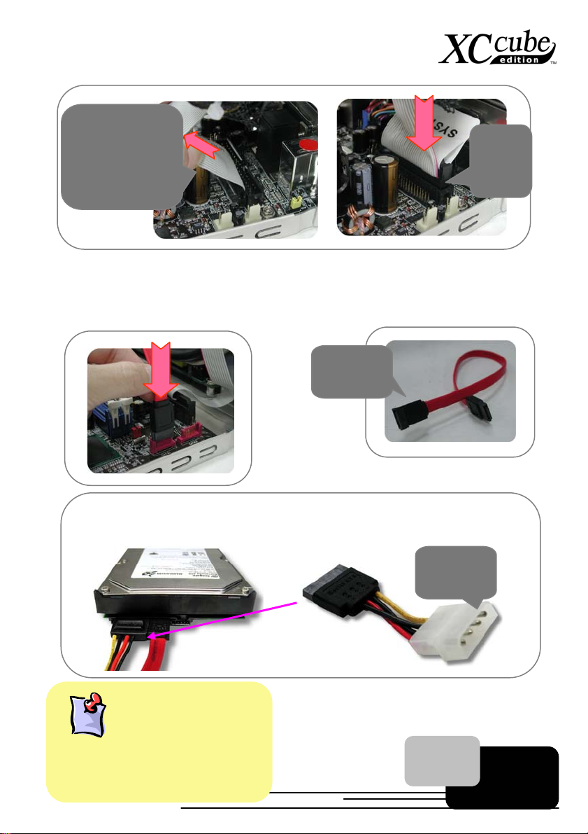
You might have to
pull Front Panel
Cable aside a bit
to find the FDD
connector.
3. If you happen to have Serial ATA hard disk, this motherboard comes with Serial ATA connectors
onboard as well. With EzColor design, you may easily find out the correct flame-red cable with
the correct header. You may kindly install the Serial ATA cables onto Serial ATA headers.
Serial ATA
Cables
Floppy
drive
cable
As Serial ATA hard disk comes with different power connector, please use our bundled
SATA power connector to connect the hard disk.
When connecting IDE cables, bear in mind to
aim the red side of IDE cables at the first pin
of the socket where there’s an ar row mark on
the motherboard. If you are still not sure,
Where is Pin1?
17
Power
Connector
Page 18
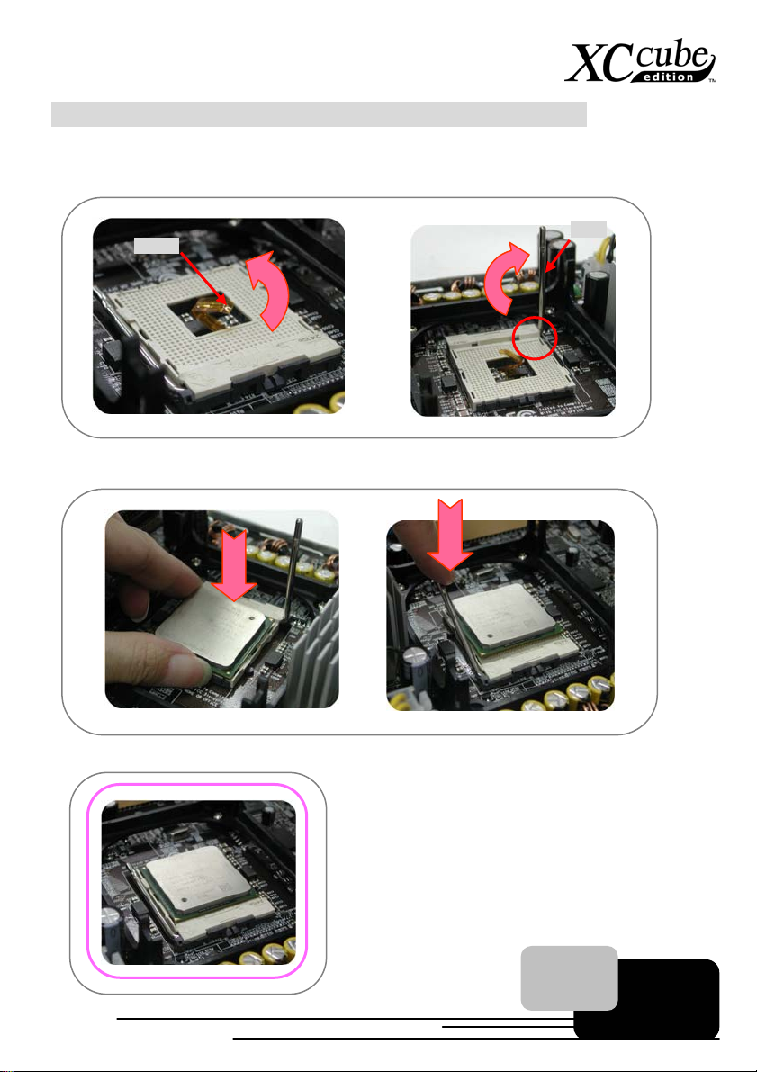
3.5 Install CPU, CPU Cooler and CPU Fan Connector
1. Erect sensor up a bit (it might have been folded while shipped in with Cooler on top of it). After
that, erect CPU socket lever up.
Sensor
2. Install CPU onto the CPU bracket. Press the lever back to CPU socket.
Lever
3. And it’s done.
18
Page 19
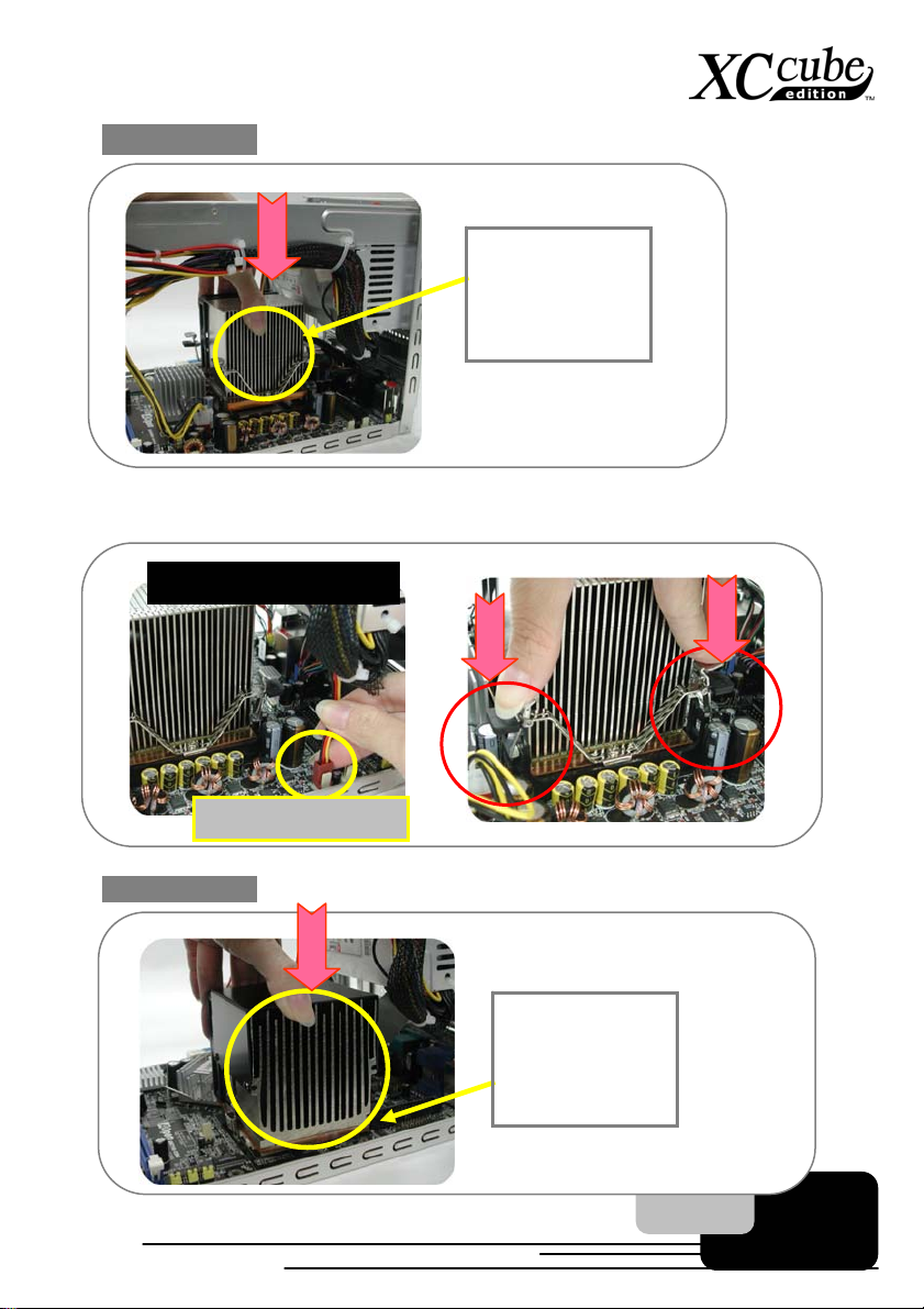
4. For EZ65 XC cube. Put CPU cooler firmly onto the CPU retention module.
The vertical side
of the Cooler
must be faced to
this side as
shown.
Connect the fan cable onto the CPU FAN connector onboard. Evenly press the iron plate
downward till you hear a “clip” sound
UX4SG-1394 motherboard
CPU Fan connector
5. For EZ18 XC cube. Put CPU cooler firmly onto the CPU retention module.
The vertical side
of the Cooler
must be faced to
this side as
shown.
19
Page 20
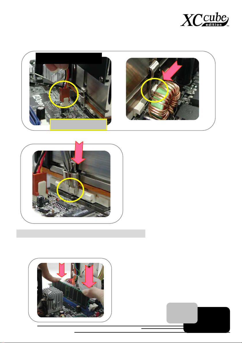
Connect the fan cable onto the fan connector onboard. Lock the right iron plate of cooler to the
socket as shown.
UX4SG-1394 motherboard
Use screwdriver to press the iron plate downward till the iron plate is firmly hooked to socket.
CPU Fan connector
3.6 Connecting DRAM to DIMM Sockets
1. DIMM socket is designed in Sky Blue color, which is very easy to recognize. Install memory
module evenly into DIMM.
20
Page 21
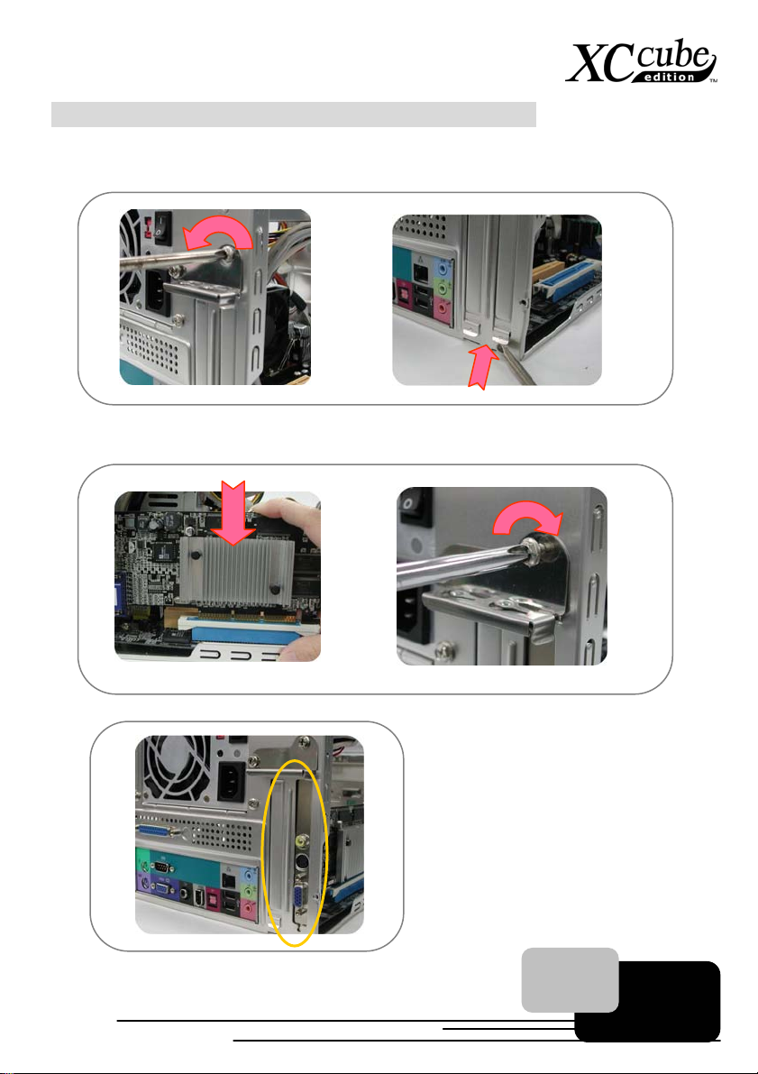
3.7 Insert AGP card or PCI card to motherboard
1. If you happen to have AGP card or PCI, you may insert them onto the AGP slot as shown.
Screw the iron plate off the back panel, and use the screwdriver to pry it out.
2. After that, please plug in the AGP card. Screw the iron lock on top of the AGP slot will do.
3. AGP card is done!
21
Page 22
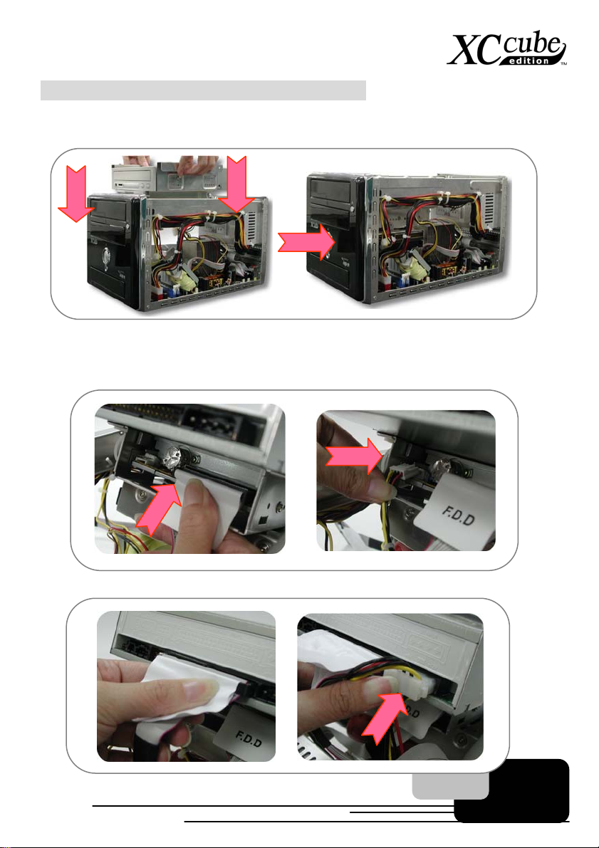
3.8 Putting Drives Cage back to Chassis
1. Putting all cables aside, and assemble the Drives Cage back to the chassis from top of the
chassis.
2. Lift the Drive Cage up at 45 degree for better installing DVD-RW and Floppy Drive.
Connecting Floppy drive and its power cord to Drive Cage:
Connecting DVD-RW drive/power cord to Drive Cage:
22
Page 23
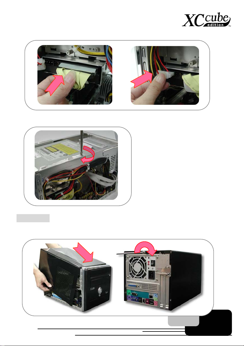
Connecting hard disk/power cord to Drive Cage:
Lock the Drives Cage with screw No. 2.
3.9 All Set
1. Assemble the housing back to the chassis. Screw the chassis back.
23 24
Page 24
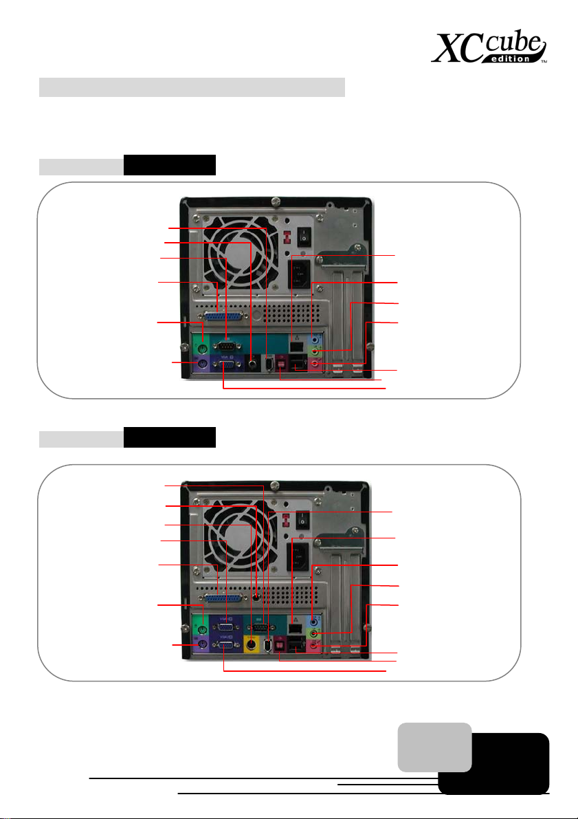
3.10 How about all external peripheral?
r
r
1. Let’s take a look at the Front Panel and Back Panel ports.
Back Panel – EZ65 XC cube
IEEE1394 connector
Coaxial RCA Port
Printer Port
keyboard connecto
PS/2
PS/2
connecto
mouse
Back Panel – EZ18 XC cube
Coaxial RCA Port
S-Video connector
VGA1 connector
Printer Port
mouse
PS/2
connecto
COM1
COM1
r
Ethernet network
r (RJ-45)
connecto
Line-In Jack
Multimedia speaker jack
Microphone jack
USB2.0 connector
S/PDIF IN port
Monitor connector
IEEE1394 connector
Ethernet network
connecto
Line-In Jack
Multimedia speaker jack
Microphone jack
r (RJ-45)
keyboard connecto
PS/2
r
USB2.0 connector
S/PDIF IN Port
VGA2 connector
Page 25
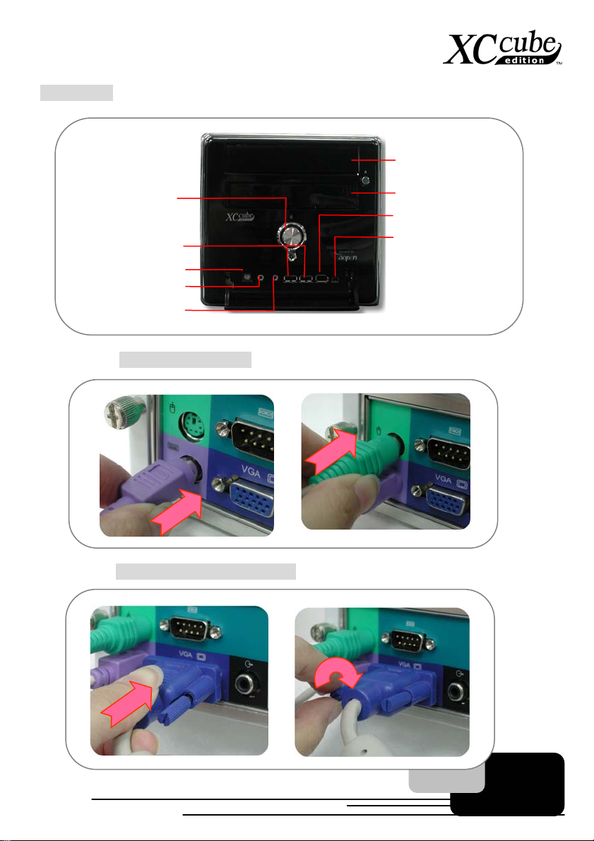
Front Panel
2. Connect keyboard and mouse.
On/Off button
USB2.0 ports
S/PDIF Out port
Speaker jack
Microphone jack
Optical Devices
Floppy Drive/Card Reader
IEEE1394 port
IEEE1394 port (4-pin)
3. Connect monitor and tighten screws
25
Page 26
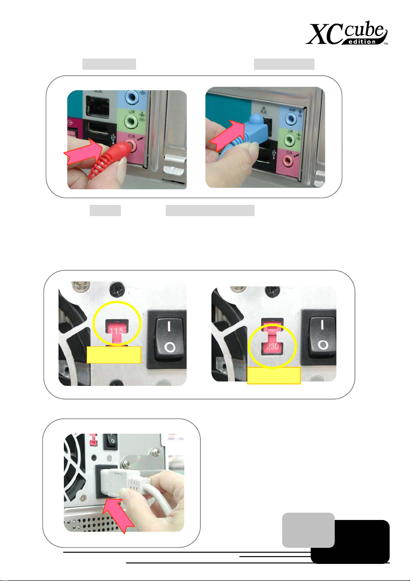
4. Connect Microphone (speaker or earphone) and network cable
5. Set proper voltage and connect power supply cable.
The voltage supplied by power outlet differs from countries or areas you dwell in. If the outlet
is supplied by 110V, please set the switch to 115V. If the outlet is supplied by 220V, please set
the switch to 230V.
Connect Power Cord Cable finally.
For 110/115V
For 220/230V
26
Page 27
[Note]
27
Page 28

Chapter 4 Turn On The Power!
Chapter 4 Turn On The Power!
1. Turn on the power.
Ok, all cables have been properly connected. Are you getting confident of assembling a
computer by yourself? The final stage is to turn on the power to check what you have done so
far. Now take a short break and have a drink. Then turn on the computer to see how things are
going.
2. Set BIOS (Basic Input/Output System).
Not long after activating the power, you'll expect to see the following screen and a line of
message saying " Press DEL to enter SETUP" at the bottom of the screen. Please press
Delete button:
Phoenix-AwardBIOS BIOS v6.00PG, An Energy Star Ally
Copyright (C) 2003, Phoenix Technologies, LTD.
L210 R0.05 July.16.2003 AOpen Inc.
Main Processor : AMD Ahtlon(tm) XP 3000+
Memory Testing : 491520K OK + 32M Shared Memory
DDR Dual Channel Enabled
Default / Setting Default / Setting
CPU 100MHz / 166MHz 1.650V / 1.650V
DRAM 333MHz / 333MHz AUTO / AUTO
AGP 66.67MHz / 66.67MHz 1.53V / 1.53V
PCI 33.33MHz / 33.33MHz 3.30V / 3.30V
Primary Master : ST30641A 3.01
Primary Slave : None
Secondary Master : None
Secondary Slave : AOpen CD-RW CRW1232PRO 1.2G
Press DEL to enter SETUP, ESC to skip memory test
07/16/2003-nVidia-nForce-6A61BABAC-00
28
Page 29
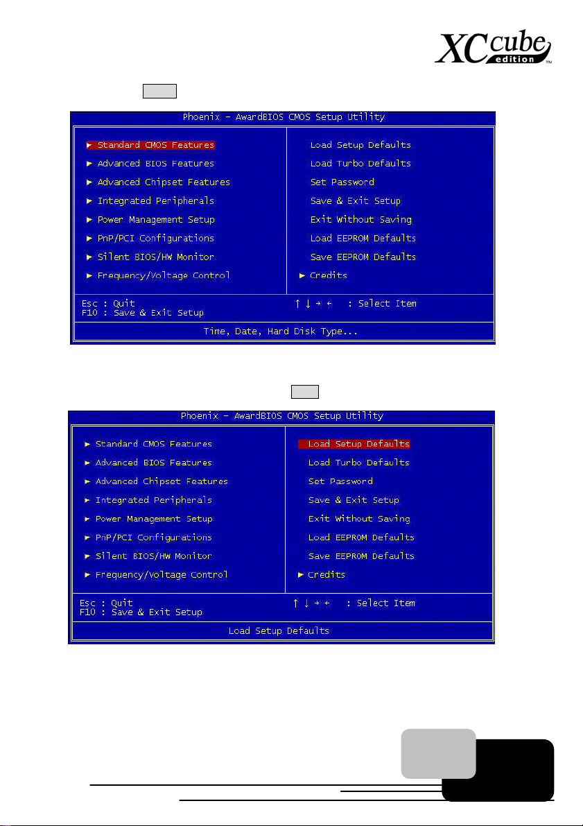
After pressing Delete, you'll see the following BIOS setup:
Now, you can move the cursor by using direction keys on the keyboard. Move the cursor to the
option item "Load Setup defaults" and press Enter
29
Page 30
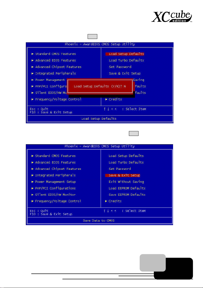
Then, the following dialogue screen will pop up to confirm the default BIOS values. Please
press "Y" to confirm and then press Enter
Finally, move the cursor to "Save & Exit Setup" and press Enter to save the parameters and
exit BIOS setup.
30
Page 31
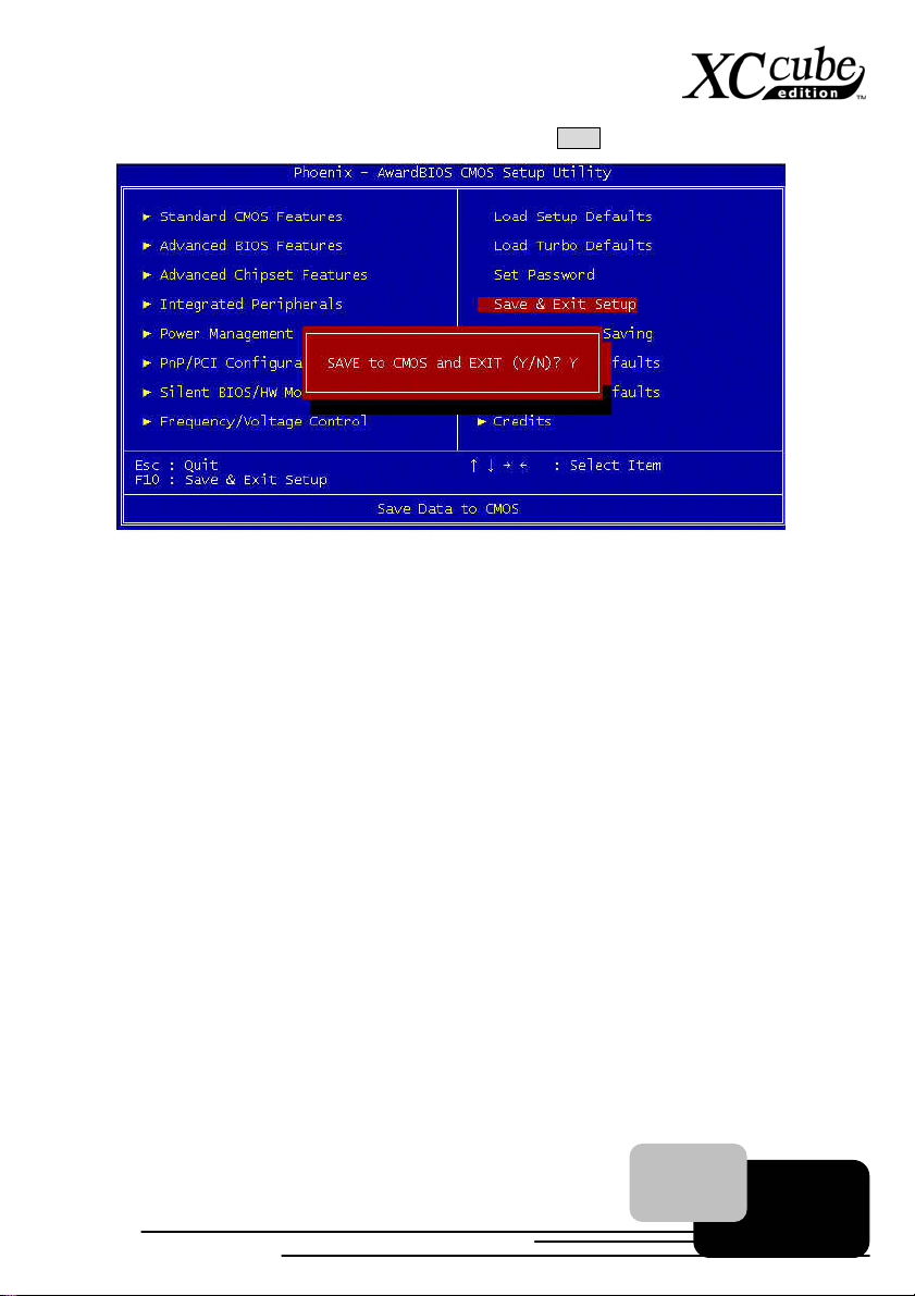
At the same time, type "Y" in the dialogue box and press Enter to exit.
Now everything is perfectly finished!!
31
Page 32
Chapter 5 Wonderful Feature Provided From AOpen
Chapter 5 Wonderful Feature Provided From AOpen
Except its unique appearance and its flexibility in moving, XC cube is equipped with many creative and
practical features. Simply introduce one of our wonderful features -- SilentTek.
SilentTek Noise Reduction Technology
1.
To get rid of unpleasant noise of the PC, SilentTek is definitely
the best helping hand you could find. Instead of adding fans onto
chipsets or any components with temperature getting higher with higher frequency given, SilentTek
allows you to monitor your system temperature and control CPU fan and system fan or even CD-ROM
speed control.
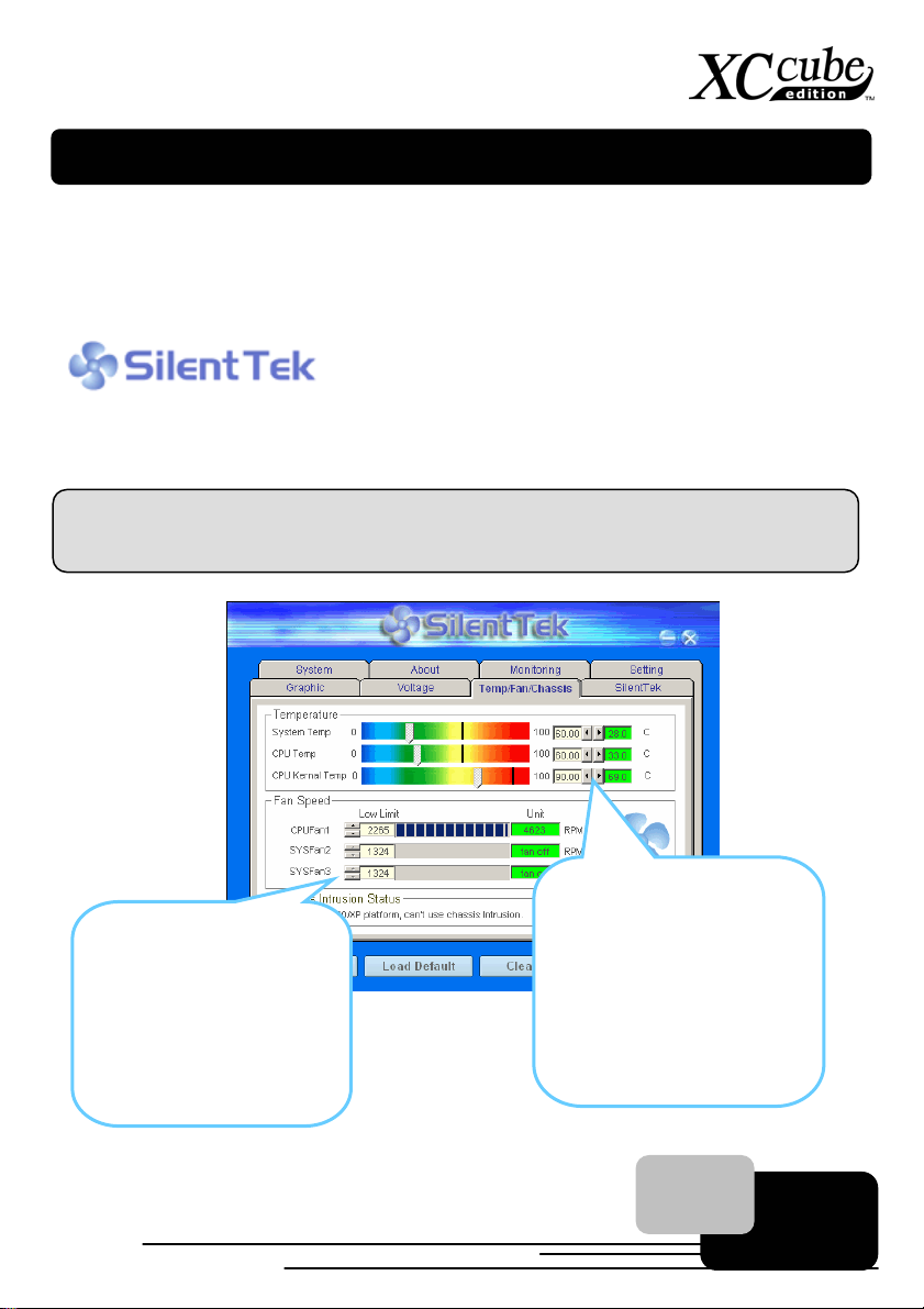
In “Temp/Fan/Case” page, you may get aware of the current temperature of CPU and the heat
inside chassis. Also, you can check if fans are running properly.
Of course, you may set a
defaulted lowest margin for
your fans. SilentTek would
also pop up a message box
to alarm you when the fan is
rotating slower than this
specified speed.
You may set the highest
margin of your CPU and
system temperature as
default, and SilentTek would
pop up a message box to alert
you with alarm when the
temperature goes beyond the
specified margin.
32
Page 33
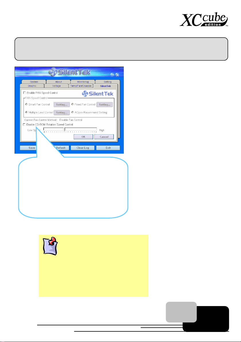
The following page is surely the most important part of this utility. You may control the rotation speed
of specific fans that you have got the options inside in this page.
CD-ROM Rotation Speed Control: by
enabling the CD-ROM Rotation Speed
Control, you can adjust the rotation speed of
your CD-ROM. When you set the speed to
high level, the CD-ROM will work at its fastest
speed and it will run at basic required speed
while you set the value to low speed.
1. Smart FAN Control: This is the default setting
of SilentTek and can be used for any branded
computer housing.
2. Fixed FAN Control: Under this setting, a
desired fan speed is set fixed when operating.
3. Multiple Level Control: This is the most
versatile setting that allows you to set fan
speed in relation to temperature.
4. AOpen Recommend Setting: This setting is
designed specifically for AOpen housing. A
series of lab tests were conducted under the
real world scenario to determine optimum fan
speed to reduce noise level within CPU
working condition and temperature.
Note:
Due to hundreds different brands of fan on the
market, inaccuracy may happen in some cases
when you had your rotation speed adjusted. It is
still under the criterion, but please rest assured
that it won’t cause any problem to your system.
33
Page 34

Postscripts
Postscripts
First of all we would like to congratulate your successful computer DIY. Now you can install an
operation system and some application software based on your personal requirements. However,
these are beyond discussions of this manual which mainly aims to teach you correct understanding of
DIY skills and enable you to assemble a computer step by step. As for the application part, you can
find all varieties of books with comprehensive introduction in bookstores.
Having a computer of your own is a beginning to the era of information. If this computer is
assembled yourself, it is uniquely meaningful to you. Through our introduction, you have learned the
key components a computer needs and what details you need to pay attention to when assembling.
We sincerely hope every customer who wants to assemble a computer on his or her own has a
wonderful beginning!
To learn more about AOpen XC cube, visit us at xc.aopen.com.tw
P/N:49.EZ101.0A1 Doc.no:EZ65EZ18B-OL-E0309A
34
Page 35
Appendix
Appendix
AOpen XC cube comes with two versions of motherboard for your selection, they are separately
UX4SG-1394 (EZ65) and UK79G-1394 (EZ18). To get to know the det ails of them, please refer to their
respective information as below.
UX4SG-1394 Motherboard
Setting CPU Voltage and Frequency
Full-range Adjustable CPU Core Voltage
This motherboard supports CPU VID function. The CPU core voltage will be automatically detected
and the range is from 1.1V to 1.85V. It is not necessary to set CPU Core Voltage.
Setting CPU Frequency
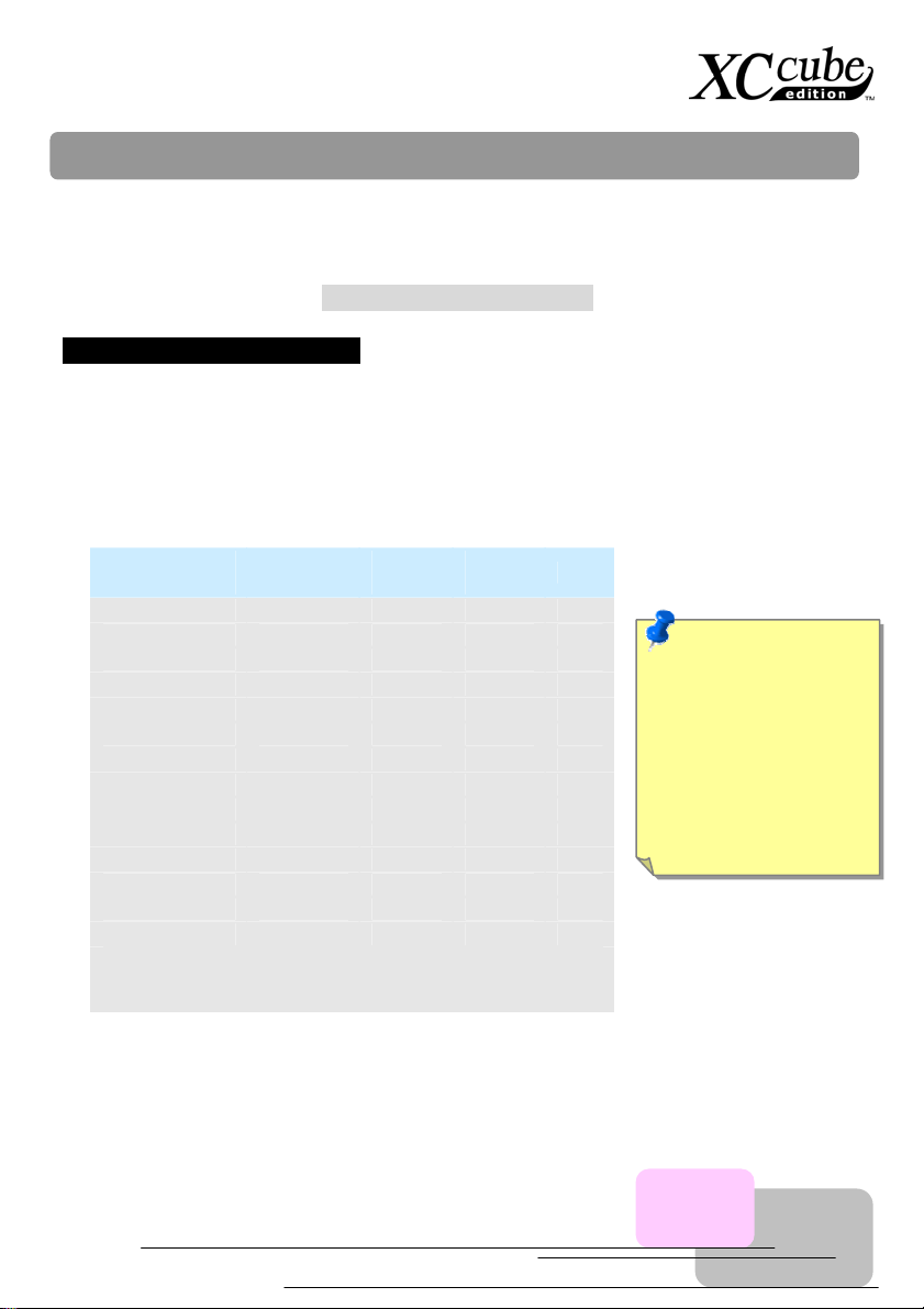
This motherboard is CPU jumper-less design, you can set CPU frequency through the BIOS setup,
and no jumpers or switches are needed.
Northwood
CPU
Pentium 4 1.8G 1800MHz 100MHz 400MHz 18x
Pentium 4 2.0G 2000MHz 100MHz 400MHz 20x
Pentium 4 2.2G 2200MHz 100MHz 400MHz 22x
Pentium 4 2.2G 2200MHz 133MHz 533MHz 16x
Pentium 4 2.26G 2260MHz 133MHz 533MHz 17x
Pentium 4 2.4G 2400MHz 100MHz 400MHz 24x
Pentium 4 2.4G 2400MHz 133MHz 533MHz 18x
Pentium 4 2.53G 2530MHz 133MHz 533MHz 19x
Pentium 4 2.6G 2600MHz 200MHz 800MHz 13x
Pentium 4 2.66G 2660MHz 133MHz 533MHz 20x
Pentium 4 2.8G 2800MHz 133MHz 533MHz 21x
Pentium 4 2.8G 2800MHz 200MHz 800MHz 14x
Pentium 4 3.06G 3000MHz 200MHz 800MHz 15x
Pentium 4 3.20G 3200MHz 200MHz 800MHz 16x
Note: With CPU speed changing rapidly, there might be fastest CPU on
the market by the time you received this installation guide. This table is
kindly for your references only.
CPU Core
Frequency
FSB
Clock
System
Bus
Ratio
Note: Intel 865G chipset
don’t support Willamette
or Celeron (0.18u)
processors. Northwood
processor would detect
the clock ratio
automatically, you may
not be able to adjust the
clock ratio in BIOS
manually.
35
Page 36
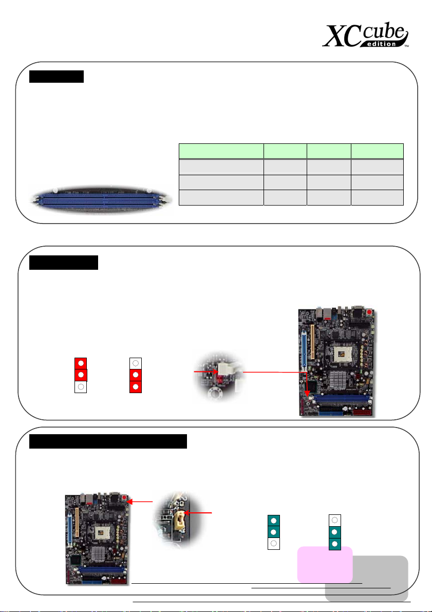
(
DIMM sockets
UX4SG-1394 allow you to install 128-bit dual channel DDR400, DDR333 or DDR266 memory up to
2GB. Only non-ECC DDR RAM is supported. Please install suitable modules; otherwise serious
damage may occur on memory sockets or you RAM modules. Please note that when you install
DDR333 memory module and have your CPU FSB set at 800MHz, the memory can only run with
the speed of DDR320. It is
limitation of Intel. For other
limitation of CPU types, please see
the table below.
JP14 Clear CMOS
Y ou can clear CMOS to restore system default setting. To clear the CMOS, follow the procedure below.
1. Turn off the system and unplug the AC power.
2. Remove ATX power cable from connector PWR2.
3. Locate JP14 and short pins 2-3 for a few seconds.
4. Return JP14 to its normal setting by shorting pin 1 & pin 2.
5. Connect ATX power cable back to connector PWR2.
1
1
Pin 1
Item DDR266 DDR333 DDR400
CPU FSB 400MHz V X X
CPU FSB 533MHz V V X
CPU FSB 800MHz V ☉ V
JP28 Keyboard/Mouse Wakeup Jumpers
You can use JP28 to enable or disable this function, which could resume your system from suspend
mode with keyboard or mouse. The factory default setting is “Disable” (1-2), and you may enable this
function by setting the jumper to 2-3.
Normal
default)
Clear CMOS
Pin 1
1 1
36
Disable
(Default)
Enable
Page 37
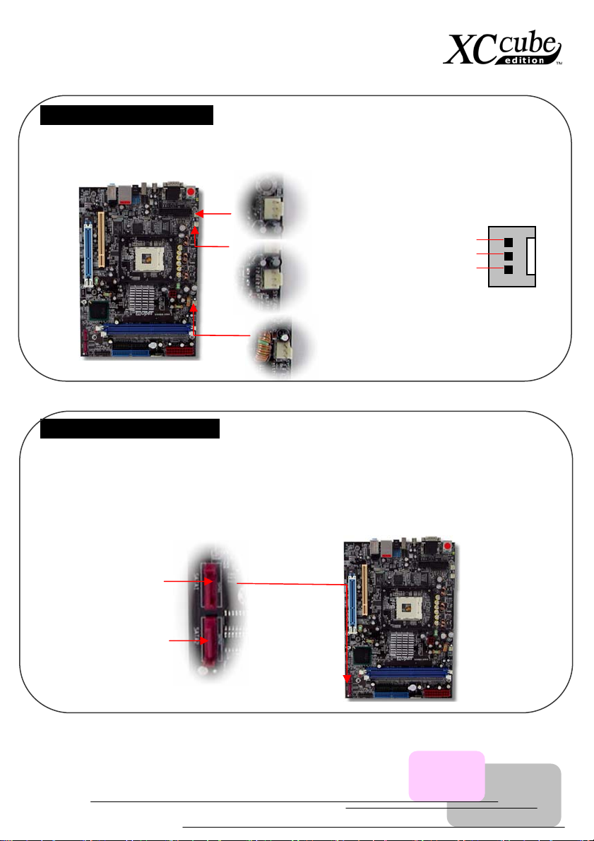
CPU and System Fan Connector
Plug in the CPU fan cable to the 3-pin CPUFAN1 connector . If you have chassis fan, you can also plug
it on SYSFAN2 or SYSFAN3 connector.
SYSFAN3 connector
CPUFAN connector
SYSFAN2 connector
GND
+12V
SENSOR
Connecting Serial ATA Connector
To connect a Serial ATA disk, you must use a 7-pin serial ATA cable. Connect two ends of the serial
ATA cable to the serial ATA header on the main board and the disk. Like every other traditional disk,
you also have to connect a power cable. Please note that it is a jumper free implement; you don’t
need to set jumpers to define a master or slave disk. When connecting two serial ATA disks, the
system will automatically take the one connected to “Serial ATA 1” header as a master disk.
SATA1 header
SATA2 header
37
Page 38
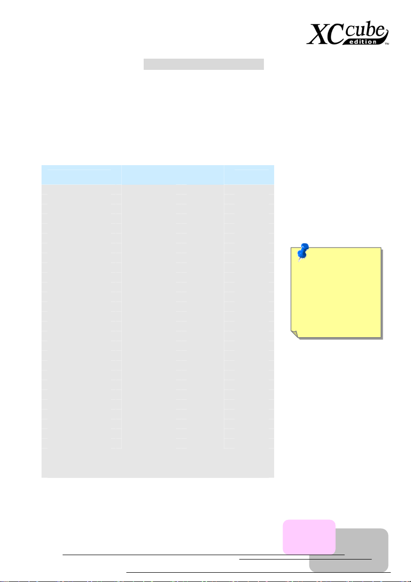
UK79G-1394 Motherboard
Full-range Adjustable CPU Core Voltage
This motherboard supports CPU VID function. The CPU core voltage will be automatically detected
and the range is from 1.1V to 1.85V. It is not necessary to set CPU Core Voltage.
Setting CPU Frequency
This motherboard is CPU jumper-less design, you can set CPU frequency through the BIOS setup,
and no jumpers or switches are needed.
CPU
Athlon 1G 1GHz 200MHz 10.0x
Athlon 1.1G 1.1GHz 200MHz 11.0x
Athlon 1.2G 1.2GHz 200MHz 12.0x
Athlon 1.3G 1.3GHz 200MHz 13.0x
Athlon 1G 1GHz 266MHz 7.5x
Athlon 1.13G 1.13GHz 266MHz 8.5x
Athlon 1.2G 1.2GHz 266MHz 9.0x
Athlon 1.33G 1.33GHz 266MHz 10.0x
Athlon 1.4G 1.4GHz 266MHz 10.5x
AthlonXP 1500+ 1.3GHz 266MHz 10.0x
AthlonXP 1600+ 1.4GHz 266MHz 10.5x
AthlonXP 1700+ 1.46GHz 266MHz 11.0x
AthlonXP 1800+ 1.53GHz 266MHz 11.5x
AthlonXP 1900+ 1.6GHz 266MHz 12.0x
AthlonXP 2000+ 1.667GHz 266MHz 12.5x
AthlonXP 2100+ 1.73GHz 266MHz 13x
AthlonXP 2200+ 1.80GHz 266MHz 13.5x
AthlonXP 2400+ 2.0GHz 266MHz 15x
AthlonXP 2600+ 2.13GHz 266MHz 16x
AthlonXP 2700+ 2.16GHz 333MHz 13x
AthlonXP 2800+ 2.25GHz 333MHz 13.5x
Duron 800 800MHz 200MHz 8.0x
Duron 850 850MHz 200MHz 8.5x
Duron 900 900MHz 200MHz 9.0x
Duron 950 950MHz 200MHz 9.5x
Duron 1G 1GHz 200MHz 10.0x
Duron 1.1G 1.1GHz 200MHz 11.0x
Note: With CPU speed changing rapidly, there might be fastest CPU on
the market by the time you received this installation guide. This table is
kindly for your references only.
CPU Core
Frequency
EV6 Bus
Clock
Ratio
Note: You have
to adjust CPU
FSB in BIOS after
installing CPU;
otherwise CPU
will run at default
speed of CPU
38
Page 39
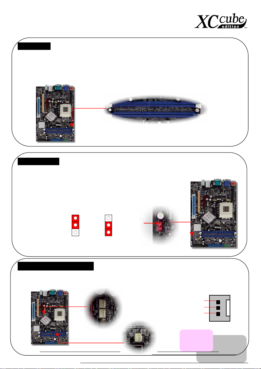
(
)
DIMM sockets
This motherboard supports DDR400/333/266 with Maximum capacity up to 2GB (When enabling VGA
onboard, memory can run max. up to 333MHz). Only Non-ECC DDR RAM is supported, otherwise, it
will cause serious damage on memory sockets or SDRAM module. For over clocking purpose, you can
adjust memory voltage in BIOS from 2.5V to 2.65V.
DIMMB1
DIMMA1
JP14 Clear CMOS
Y ou can clear CMOS to restore system default setting. To clear the CMOS, follow the procedure below.
1. Turn off the system and unplug the AC power.
2. Remove ATX power cable from connector PWR2.
3. Locate JP14 and short pins 2-3 for a few seconds.
4. Return JP14 to its normal setting by shorting pin 1 & pin 2.
5. Connect ATX power cable back to connector PWR2.
1
1
Pin 1
Normal
default
Clear CMOS
CPU and System Fan Connector
Plug in the CPU fan cable to the 3-pin CPUFAN1 connector. If you have chassis fan, you can also plug
it on SYSFAN2 or SYSFAN3 connector.
SYSFAN3 connector
SYSFAN2 connector
39
CPUFAN connector
GND
+12V
SENSOR
Page 40
Pin 1
(
)
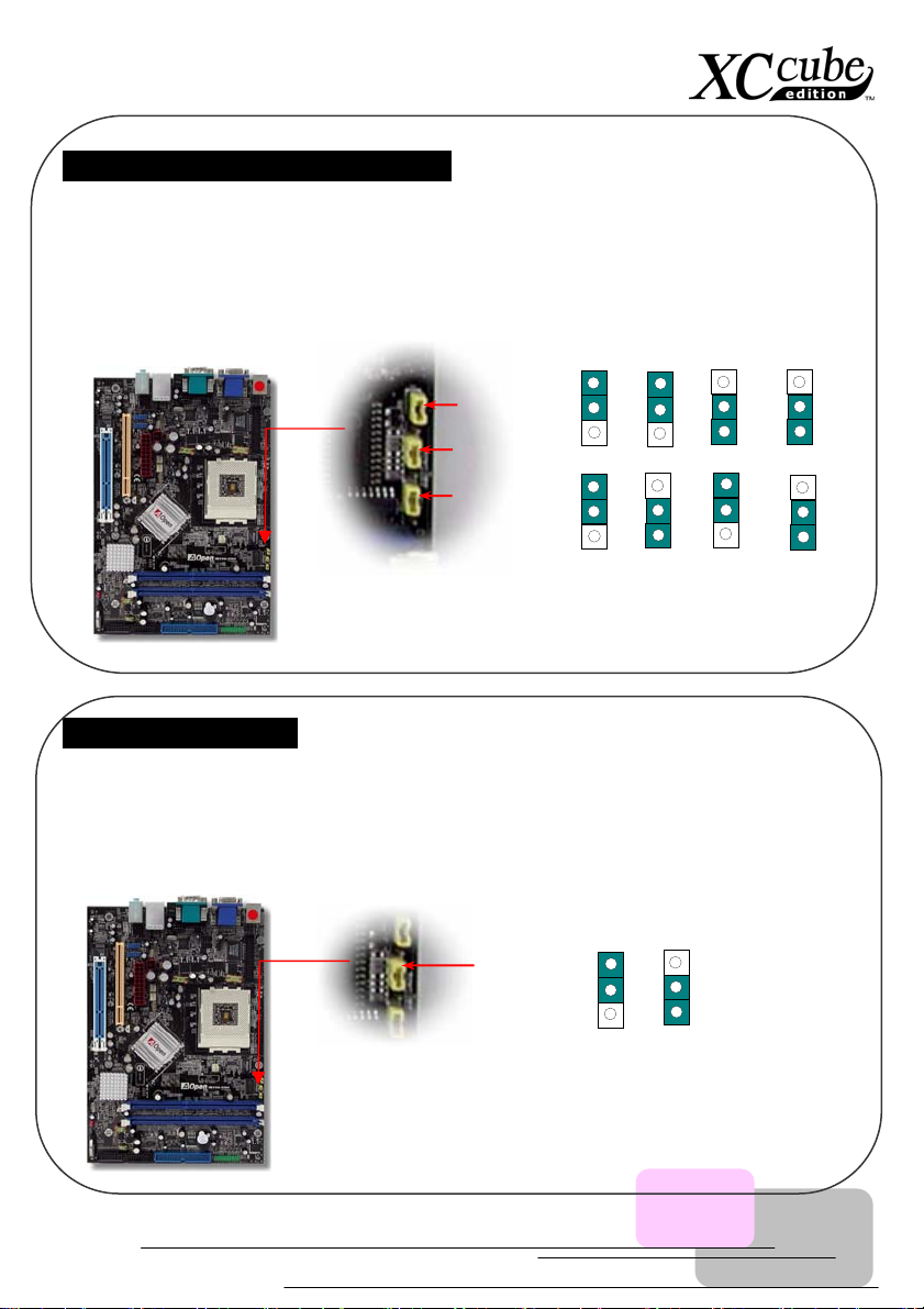
JP15/JP16 Dr. Voice Language Select Jumpers
Dr. Voice is a great feature, which can identify the problems you may encounter in the operating
system. It can clearly “tell you” whether the problem is caused from components or improper
installation such as CPU, memory module, VGA, PCI add-on card, FDD, HDD or keyboard. Dr. Voice
provides four language versions: English, German, Japanese and Chinese. You can select your
preferred language by JP15 & JP16 jumpers. However, you may also set JP2 to choose making out
voices from buzzer or speaker.
JP2 Speaker Output Jumper
This motherboard comes with another considerate option that allows you to turn off the voice from
buzzer and speaker. You can choose not to be bothered by the warning made from Dr. Voice when it
detects any error in operating system. You may also set JP2 to choose sending out voices from buzzer
or speaker.
JP16 jumper
JP2 jumper
JP15 jumper
JP16
JP15
English
(Default)
Japanese
Chinese
Pin1
Pin1
German
1
Speaker
JP2 jumper
1
Buzzer
default
40
 Loading...