

Page 1

DDXXPPNN--UU OOnnlliinnee MMaannuuaall
DXPN-U
DOC. NO.: DXPNU-OL-E0306A
Overview
Installation
Hardware
Drivers &
Utilities
BIOS Setup
Glossary
Troubleshooting &
Technical Support
1
Page 2

DDXXPPNN--UU OOnnlliinnee MMaannuuaall
WWhhaatt’’ss iinn tthhiiss mmaannuuaall
DXPN-U .........................................................................................................................................1
What’s in this manual ...................................................................................................................................................... 2
You Must Notice .............................................................................................................................................................. 7
Before You Start.............................................................................................................................................................. 8
Overview ......................................................................................................................................................................... 9
Feature Highlight........................................................................................................................................................... 10
Quick Installation Procedure .........................................................................................................................................13
Motherboard Map.......................................................................................................................................................... 14
Hardware Installation................................................................................................................15
About “User Upgrade Optional” and “Manufacture Upgrade Optional”… ....................................................................... 16
CPU Installation ............................................................................................................................................................ 17
Installing CPU and Housing Fans.................................................................................................................................. 18
AGP 8x (Accelerated Graphic Port) Expansion Slot ...................................................................................................... 19
DIMM Sockets ............................................................................................................................................................... 20
Multi Function Panel Connector .................................................................................................................................... 23
ATX Power Connector................................................................................................................................................... 24
AC Power Auto Recovery .............................................................................................................................................. 25
2
Page 3

DDXXPPNN--UU OOnnlliinnee MMaannuuaall
IDE and Floppy Connector ............................................................................................................................................ 26
ATA100 Supported ........................................................................................................................................................ 28
PC99 Color Coded Back Panel ..................................................................................................................................... 29
Chassis Intrusion Sensor ..............................................................................................................................................30
JP1 Check Password Jumper........................................................................................................................................ 31
JP3 Clear CMOS Jumper .............................................................................................................................................. 32
JP4 BIOS Configuration / Recovery Select Jumper....................................................................................................... 33
Support Two USB2.0 Channels (Four Ports) .................................................................................................................34
WOL (Wake on LAN) ..................................................................................................................................................... 36
STBY LED..................................................................................................................................................................... 38
Resettable Fuse ............................................................................................................................................................ 39
Low ESR Capacitor ....................................................................................................................................................... 40
Driver and Utility .......................................................................................................................41
BIOS Setup Utility ..................................................................................................................... 42
Entering Setup .............................................................................................................................................................. 43
System Information ....................................................................................................................................................... 46
Product Information....................................................................................................................................................... 51
Disk Devices .................................................................................................................................................................53
Onboard Peripherals ..................................................................................................................................................... 61
3
Page 4

DDXXPPNN--UU OOnnlliinnee MMaannuuaall
Power Management ...................................................................................................................................................... 68
Boot Options .................................................................................................................................................................75
Date and Time............................................................................................................................................................... 79
System Security ............................................................................................................................................................81
Health Monitor Status .................................................................................................................................................... 85
Load Default Settings.................................................................................................................................................... 86
Abort Settings Change .................................................................................................................................................. 87
Glossary ....................................................................................................................................88
AC97 CODEC ............................................................................................................................................................... 88
ACPI (Advanced Configuration & Power Interface) ....................................................................................................... 88
ACR (Advanced Communication Riser)......................................................................................................................... 88
AGP (Accelerated Graphic Port) ................................................................................................................................... 89
AMR (Audio/Modem Riser)............................................................................................................................................ 89
ATA (AT Attachment) ..................................................................................................................................................... 89
BIOS (Basic Input/Output System) ................................................................................................................................ 90
Bluetooth....................................................................................................................................................................... 90
CNR (Communication and Networking Riser)................................................................................................................ 91
DDR (Double Data Rate) RAM ...................................................................................................................................... 91
ECC (Error Checking and Correction) ........................................................................................................................... 92
4
Page 5

DDXXPPNN--UU OOnnlliinnee MMaannuuaall
EEPROM (Electronic Erasable Programmable ROM)....................................................................................................92
EPROM (Erasable Programmable ROM) ...................................................................................................................... 92
EV6 Bus ........................................................................................................................................................................ 92
FCC DoC (Declaration of Conformity) ........................................................................................................................... 93
FC-PGA (Flip Chip-Pin Grid Array)................................................................................................................................ 93
FC-PGA2 (Flip Chip-Pin Grid Array) .............................................................................................................................. 93
Flash ROM .................................................................................................................................................................... 93
Hyper Threading ........................................................................................................................................................... 93
IEEE 1394..................................................................................................................................................................... 94
Parity Bit .......................................................................................................................................................................94
PCI (Peripheral Component Interface) Bus ...................................................................................................................95
PDF Format................................................................................................................................................................... 95
PnP (Plug and Play)...................................................................................................................................................... 95
POST (Power-On Self Test) ..........................................................................................................................................95
PSB (Processor System Bus) Clock .............................................................................................................................. 96
RDRAM (Rambus Dynamic Random Access Memory).................................................................................................. 96
RIMM (Rambus Inline Memory Module) ........................................................................................................................96
SDRAM (Synchronous DRAM) ...................................................................................................................................... 96
SATA (Serial ATA) ......................................................................................................................................................... 97
5
Page 6

DDXXPPNN--UU OOnnlliinnee MMaannuuaall
SMBus (System Management Bus) ............................................................................................................................... 97
SPD (Serial Presence Detect) ....................................................................................................................................... 97
USB 2.0 (Universal Serial Bus) ..................................................................................................................................... 97
VCM (Virtual Channel Memory).....................................................................................................................................98
Wireless LAN – 802.11b ................................................................................................................................................ 98
ZIP file........................................................................................................................................................................... 98
Troubleshooting......................................................................................................................... 99
Technical Support ...................................................................................................................103
Product Registration ............................................................................................................... 107
How to Contact Us .................................................................................................................. 108
6
Page 7

DDXXPPNN--UU OOnnlliinnee MMaannuuaall
YYoouu MMuusstt NNoottiiccee
Adobe, the Adobe logo, Acrobat is trademarks of Adobe Systems Incorporated.
AMD, the AMD logo, Athlon and Duron are trademarks of Advanced Micro Devices, Inc.
Intel, the Intel logo, Intel Celeron, Pentium II, Pentium III, Pentium 4 and Xeon
Microsoft, Windows, and Windows logo are either registered trademarks or trademarks of Microsoft Corporation in the United
States and/or other countries.
All product and brand names used on this manual are used for identification purposes only and may be the registered
trademarks of their respective owners.
All of the specifications and information contained in this manual are subject to change without notice. AOpen reserves the right
to revise this publication and to make reasonable changes. AOpen assumes no responsibility for any errors or inaccuracies that
may appear in this manual, including the products and software described in it.
This documentation is protected by copyright law. All rights are reserved.
No part of this document may be used or reproduced in any form or by any means, or stored in a database or retrieval
system without prior written permission from AOpen Corporation.
Copyright
©
1996-2003, AOpen Inc. All Rights Reserved.
TM
are trademarks of Intel Corporation.
7
Page 8

DDXXPPNN--UU OOnnlliinnee MMaannuuaall
BBeeffoorree YYoouu SSttaarrtt
This Online Manual will introduce you how this product is installed. All useful information will be described in later chapters.
Please keep this manual carefully for future upgrades or system configuration changes. This Online Manual is saved in PDF
format, we recommend using Adobe Acrobat Reader 4.0 for online viewing, it is included in Bonus CD disc or you can get free
download from Adobe web site
Although this Online Manual is optimized for screen viewing, it is still capable for hardcopy printing, you can print it by A4 paper
size and set 2 pages per A4 sheet on your printer. To do so, choose File > Page Setup and follow the instruction of your printer
driver.
Thanks for the help of saving our earth.
.
8
Page 9

DDXXPPNN--UU OOnnlliinnee MMaannuuaall
OOvveerrvviieeww
Thank you for choosing AOpen DXPN-U motherboard. DXPN-U is Intel® Socket 604 motherboard (M/B) based on the BIG ATX
form factor featuring the Intel
®
Socket 604 Intel® Xeon™ and up to 533MHz Front Side Bus (FSB) clock.The DXPN-U also integrates the Intel® 82540
Intel
GbE PCI Ethernet controller that supports 1 Gbites function for better remote site management. According to different
customer’s requirements, the chipset memory interface supports ECC DDR RAM devices with densities of 64, 128, 256, 512Mb,
and 1Gb DDR RAM DIMM modules and the maximum memory size can be up to 4GB.
®
E7505 Chipset. As high performance chipset built in the M/B, DXPN-U motherboard can support
9
Page 10

DDXXPPNN--UU OOnnlliinnee MMaannuuaall
FFeeaattuurree HHiigghhlliigghhtt
CPU
Supports Intel® Xeon™ 1.8GHz above with up to FSB533MHz (Front Side Bus) designed for Socket 604 technology.
Chipset
With Intel® E7505 chipset is designed for use with the Intel® Xeon™ processor in the 604-pin package. It is optimized for the
®
Intel
Xeon™ processor, supporting Dual channel of DDR 200/266.
Expansion Slots
Including four 64-bit/66/100MHz PCI-X and one 32-bit/33MHz PCI slots.
Intel® 82540 GbE LAN controller
Another cost-effective feature for network solution is the integration of Intel 82540 GbE Fast Ethernet controllers. The Intel
82540 GbE integrates Intel’s fourth-generation Gigabit MAC design with fully integrated, physical-layer circuitry to provide a
standard IEEE 802.3 Ethernet interface for 1000BASE-T and 100BASE-TX applications.
Memory
The motherboard has four 184-pin DDR DIMM sockets. It supports DDR200/266MHz ECC unbuffered memory and is up to
10
Page 11

DDXXPPNN--UU OOnnlliinnee MMaannuuaall
4GB maxium. The socket can support 64, 128, 256, 512 and 1GB DDR DIMM modules.
USB2.0 Connectors
There are two connectors on the back pane for USB interface devices, such as mouse, keyboard, modem, scanner, etc. All two
USB Connectors support USB2.0. You can use proper cables to connect USB devices from PC99 back panel or connect the
second USB channel header to the front panel of chassis.
Power Management/Plug and Play
Supports the power management function that conforms to the power-saving standards of the U.S. Environmental Protection
Agency (EPA) Energy Star program. It also offers Plug-and-Play
system user-friendly.
, helping save users from configuration problems and makes the
Hardware Monitoring Management
Supports CPU or system fans’ status, temperature, voltage monitoring and alert through the on-board hardware monitor module.
Enhanced ACPI
The fully implemented ACPI standard is Windows® 2000 series compatible; it also supports S1, S3, S4, S5 features.
11
Page 12

DDXXPPNN--UU OOnnlliinnee MMaannuuaall
Super Multi-I/O
Provides two high-speed UART compatible serial ports and one parallel port with EPP and ECP capabilities. You can also
connect UART from COM1 to an Infrared Module for wireless connection.
12
Page 13

DDXXPPNN--UU OOnnlliinnee MMaannuuaall
QQuuiicckk IInnssttaallllaattiioonn PPrroocceedduurree
This page gives you a quick procedure on how to install your system. Follow each step accordingly.
1. Installing CPU and Fan
2. Installing System Memory (DIMM)
3. Connecting Front Panel Cable
4. Connecting IDE and Floppy Cable
5. Connecting ATX Power Cable
6. Connecting Back Panel Cable
7. Power-on and Load BIOS Setup Default
8. Setting CPU Frequency
9. Reboot
10. Installing Operating System
11. Installing Driver and Utility
13
Page 14
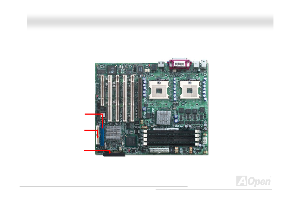
DDXXPPNN--UU OOnnlliinnee MMaannuuaall
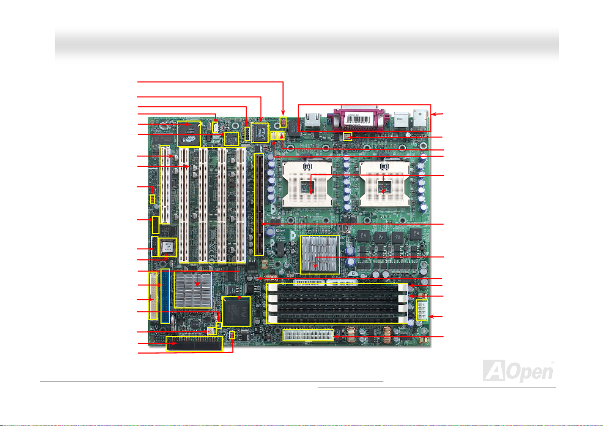
JP1 BIOS Password ON/OFF
Jumper
64bit/66/100MHz PCI-X Slot x4
JP4 BIOS Configuration /
Recovery Select Jumper
Multi function Panel Connector
South Bridge: Intel ICH4+P64H2
Primary IDE Connector(IDE1)
Secondary IDE Connector(IDE2)
Super I/O Controller
COM2 Connector
Wake On LAN Connector
ATI Rage XL Controller
Intel® 82540 GbE Ethern
32bit/33MHz 5V PCI Slot x1
Chassis Fan2 Connector
JP3 Clear CMOS Jumper
et Controller
USB2.0 connector
Flash ROM BIOS
FDD Connector
Standby LED
Motherboard Map
PC99 Back Panel
CPU1 Fan Connector
CPU2 Fan Connector
Chassis Fan 1 Connector
604-pin CPU socket x2 up to
FSB533 MHz Intel
CPU Supported
AGP 8X Pro Slot
Intel E7505 Chipset
184-pin DIMM Sockets x4
supports ECC, unbuffer,
DDR200/266 DDR RAM
EPS 8-pin 12V Power Connector
pin 12V Power Connector
EPS 24-
®
TM
Xeon
14
Page 15

DDXXPPNN--UU OOnnlliinnee MMaannuuaall
HHaarrddwwaarree IInnssttaallllaattiioonn
This chapter describes jumpers, connectors and hardware devices of this motherboard.
Note: Electrostatic discharge (ESD) can damage your processor, disk drives, expansion boards, and
other components. Always observe the following precautions before you install a system component.
1. Do not remove a component from its protective packaging until you are ready to install it.
2. Wear a wrist ground strap and attach it to a metal part of the system unit before handling a
component. If a wrist strap is not available, maintain contact with the system unit throughout any
procedure requiring ESD protection.
15
Page 16

DDXXPPNN--UU OOnnlliinnee MMaannuuaall
AAbboouutt ““UUsseerr UUppggrraaddee OOppttiioonnaall”” aanndd ““MMaannuuffaaccttuurree UUppggrraaddee
OOppttiioonnaall””……
When you read this online manual and start to assemble your computer system, you may notice that some of the functions are
marked as “User Upgrade Optional” or “Manufacture Upgrade Optional”. Although all of AOpen’s motherboards have included
many amazing and powerful features, sometimes not every user is familiar with these powerful features. As a result of this we
define features that can be upgraded by users as “User Upgrade Optional”. You can upgrade these functions by purchasing
additional devices. As for functions that cannot be upgraded by users, we define them as “Manufacture Upgrade Optional”. If
need be, you can contact our local distributors or resellers to purchase “Manufacture Upgrade Optional” components, and again
you are also welcome to visit our official website at Http://english.aopen.com.tw
for detail information.
16
Page 17
DDXXPPNN--UU OOnnl
liinnee MMaannuuaall
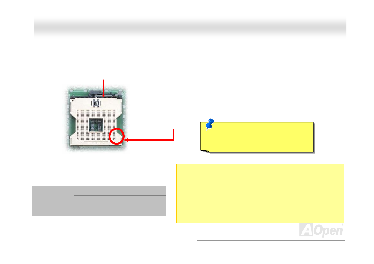
CCPPUU IInnssttaallllaattiioonn
This motherboard supports Intel® XeonTM Socket 604 series CPU. Be careful of CPU orientation when you plug it into CPU
socket.
Config1
Config2 V V
CPU socket lever
CPU1 CPU2
V N/A
CPU cut edge
1. Pull up the CPU socket level and up to 90-degree angle.
2. Locate Pin 1 in the socket and look for a (golden) cut
edge on the CPU upper interface. Match Pin 1 and cut
edge. Then insert the CPU into the socket.
3. Press down the CPU socket level and finish CPU
installation.
Caution: If you do no t match the CPU
socket Pin 1 and CPU cut edge well,
you may damage the CPU.
Notes:
1. Config1: CPU socket 1 is for single CPU setup
2. Config2: The same CPU frequency for both CPUs is a must!
17
Page 18
DDXXPPNN--UU OOnnlliinnee MMaannuuaall
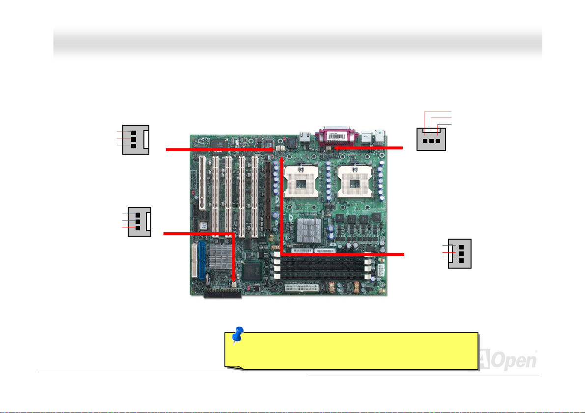
IInnssttaalllliinngg CCPPUU aanndd HHoouussiinngg FFaannss
Plug in the CPU fan cable to the 3-pin CPU FAN connector and System Fan cable to the Chassis Fan connectors.
SENSOR
+12V
GND
Chassis FAN1
SENSOR
+12V
GND
Chassis FAN2
Note: Some CPU fans do not have sensor pin, so that cannot
support fan monitoring.
SENSOR
+12V
GND
CPU1 Fan
GND
+12V
SENSOR
CPU2 FAN
18
Page 19
DDXXPPNN--UU OOnnlliinnee MMaannuuaall
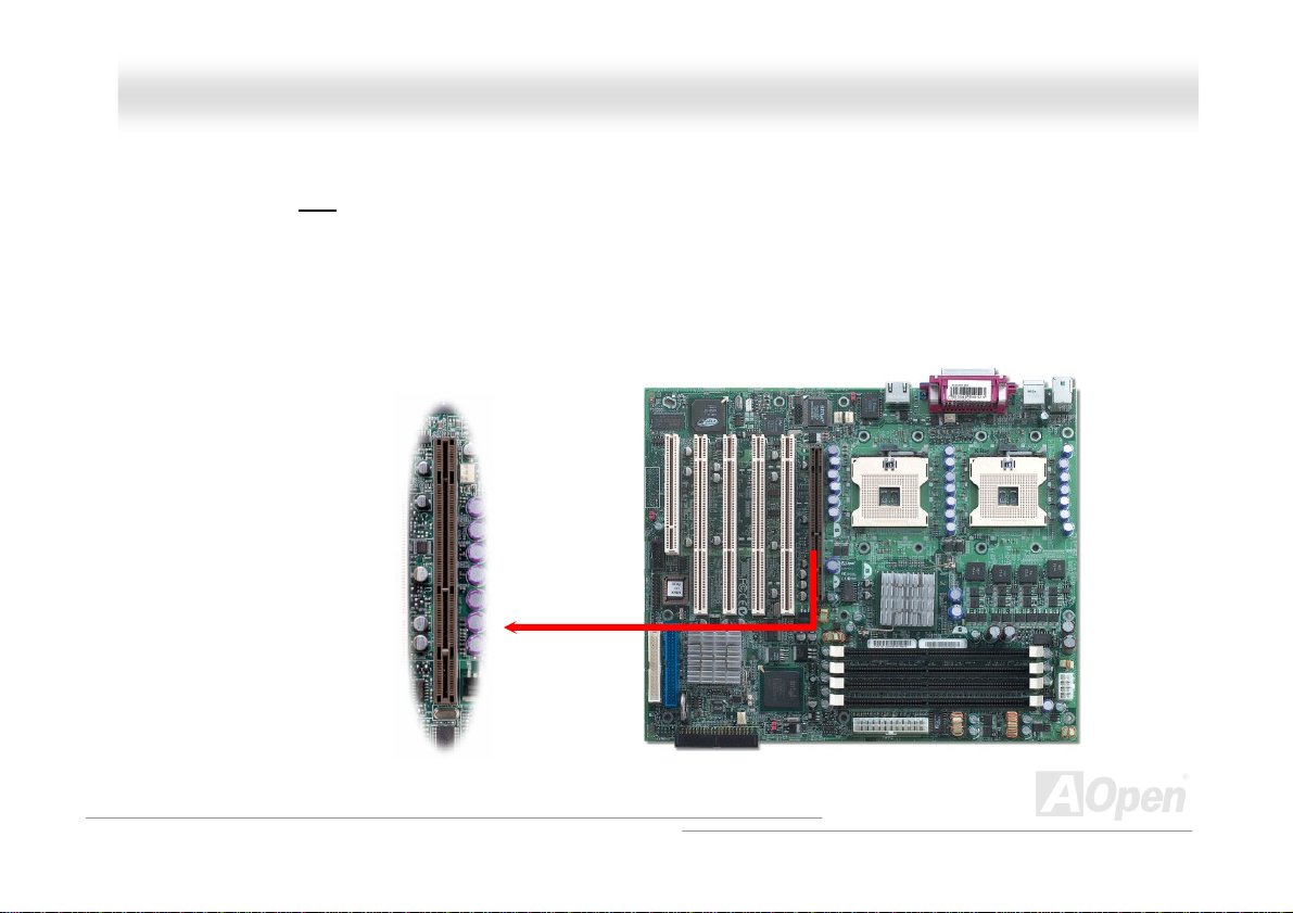
AAGGPP 88xx ((AAcccceelleerraatteedd GGrraapphhiicc PPoorrtt)) EExxppaannssiioonn SSlloott
DXPN-U provides an AGP 8x slot. Accelerated Graphics Port (AGP) is a high-performance, component level interface targeted
at 3D graphical display applications. Retaining backward compatibility with the older AGP 4x technology, AGP 8x doubles the
graphics bandwidth of the AGP interface to 2.1 gigabytes per second (GB/s) which is designed to benefit applications on today's
most popular workstation platforms.
19
Page 20
DDXXPPNN--UU OOnnlliinnee MMaannuuaall
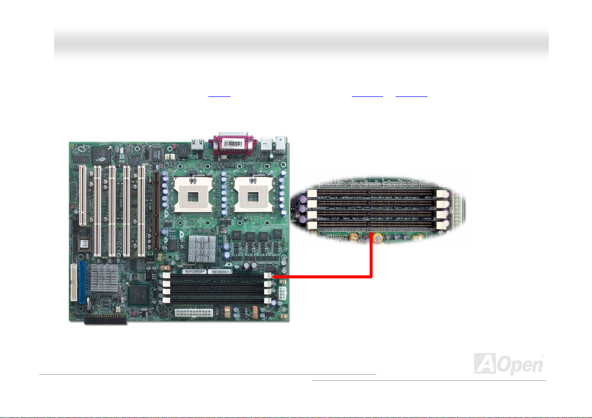
DDIIMMMM SSoocckkeettss
This motherboard has four 184-pin DDR DIMM sockets that allow you to install DDR200 or DDR266 ECC memory up to 4GB.
The unbuffer DDR RAM is supported.
DIMM 1
DIMM 2
DIMM 3
DIMM 4
20
Page 21

DDXXPPNN--UU OOnnl
Notes:
1. 256MB, 512MB, 1GB ECC un-buffer DIMM alternative
2. Config1: It is for RAM installation.
3. Config2: Both DIMMs need to be with the same manufacture and capacity.
4. Config3: Each group or these two groups needs the same manufacture and capacity.
5. Single bank shall be put in DIMM1/2. Double bank shall be put in DIMM3/4 while
Config1
Config2
Config3
installing them together.
DIMM1 DIMM2 DIMM3 DIMM4
V V N/A N/A
N/A N/A
V V V V
V V
liinnee MMaannuuaall
21
Page 22
DDXXPPNN--UU OOnnlliinnee MMaannuuaall
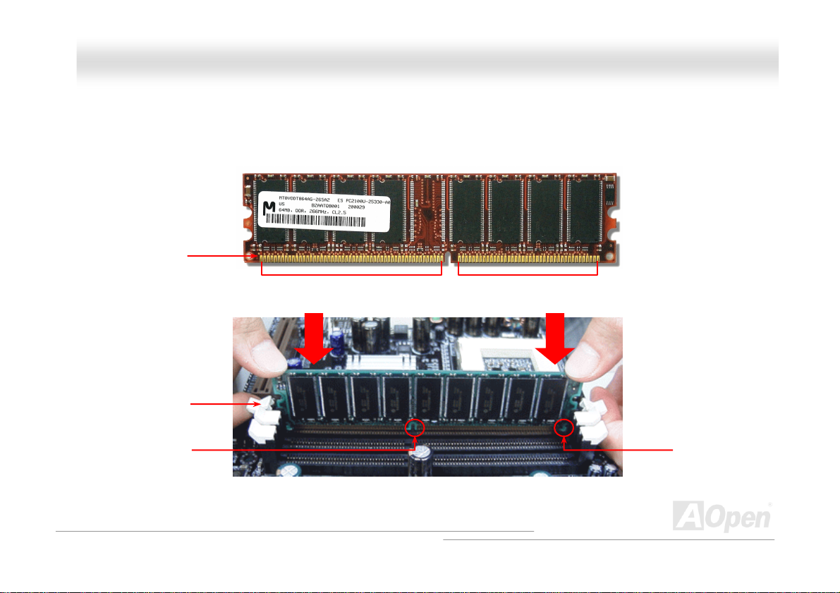
HHooww ttoo IInnssttaallll MMeemmoorryy MMoodduulleess
Please follow the procedure as shown below to finish memory installation.
1. Make sure the DIMM module’s pin face down and match the socket’s size as depicted below.
2. Insert the module straight down to the DIMM slot with both hands and press down firmly until the DIMM module is securely
in place.
3. Repeat step 2 to finish additional DIMM modules installation.
Pin 1
Ta b
Key
52 pins 40 pins
Pin 1
22
Page 23
DDXXPPNN--UU OOnnlliinnee MMaannuuaall
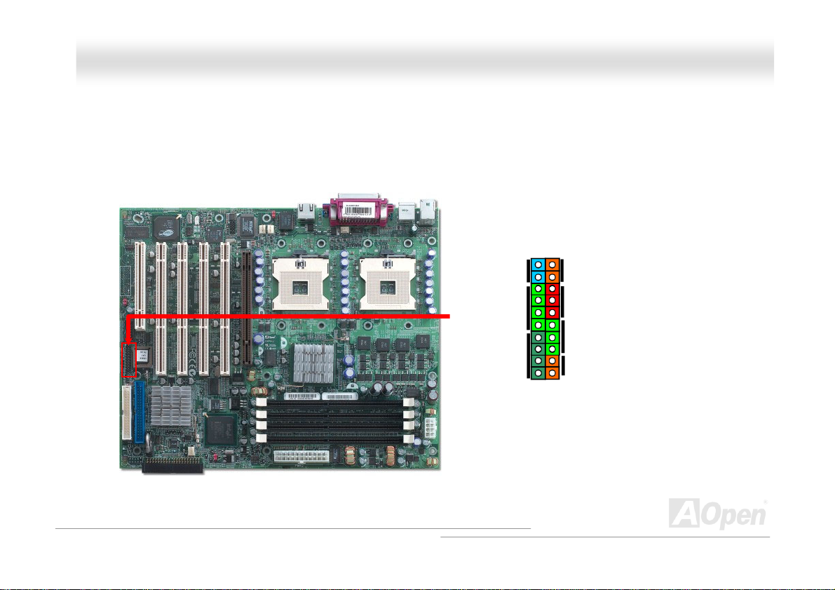
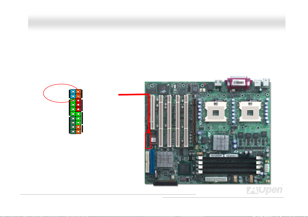
MMuullttii FFuunnccttiioonn PPaanneell CCoonnnneeccttoorr
Attaching such as power switch, reset switch, HDD LED connector, etc to corresponding pins. Locate the power switch
cable from your ATX housing. It is 2-pin female connector from the housing front panel. Plug this connector to the
soft-power switch connector marked SPWR.
1
Intruder
IDE LED
Spea ker
Power Switch
ACPI & Power LED
External NMI
Reset
23
Page 24
DDXXPPNN--UU OOnnlliinnee MMaannuuaall
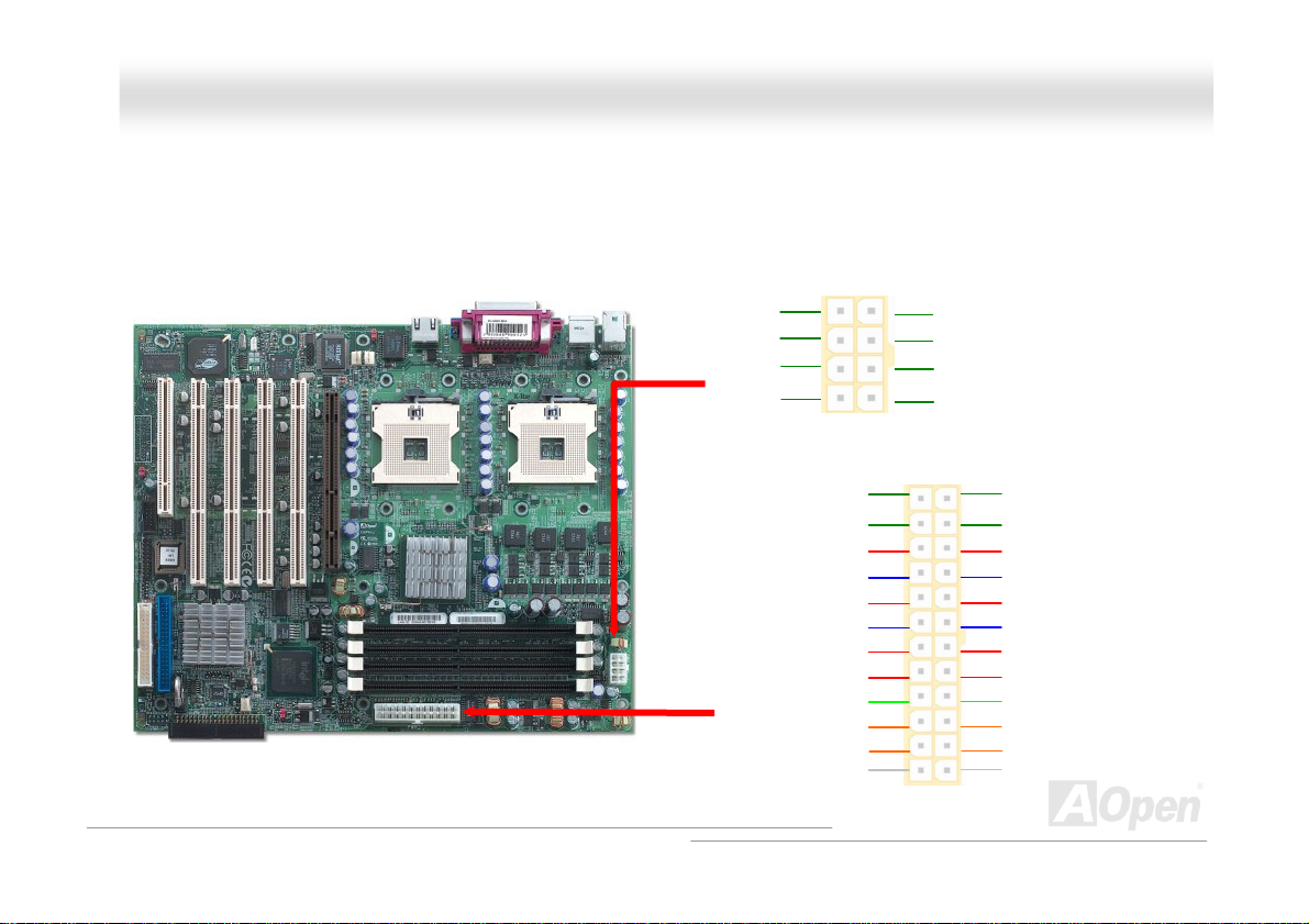
AATTXX PPoowweerr CCoonnnneeccttoorr
This motherboard comes with a 24-pin and 8-pin ATX power connector. Make sure you plug in the right direction. We strongly
recommend you to connect the 8-pin 12V ATX connector before connecting the 24-pin ATX power connector
GND
GND
GND
GND
+3.3V
+12V
+12V
+5Vsb
PWR_OK
Ground
+5V
Ground
+5V
Ground
+3.3V
+3.3V
+12V
+12V
+12V
+12V
2 1
Ground
+5V
+5V
+5V
NC
Ground
Ground
Ground
PS_ON
Ground
12V
+3.3V
24
Page 25

DDXXPPNN--UU OOnnlliinnee MMaannuuaall
AACC PPoowweerr AAuuttoo RReeccoovveerryy
A traditional ATX system remains at power off stage when AC power resumes from power failure. This design is inconvenient for
a network server or workstation without an UPS. This motherboard implements an AC Power Auto Recovery function to solve
this problem.
25
Page 26
DDXXPPNN--UU OOnnlliinnee MMaannuuaall
IIDDEE aanndd FFllooppppyy CCoonnnneeccttoorr
Connect 34-pin floppy cable and 40-pin IDE cable to floppy connector FDC and IDE connector. Pin1 of cable is normally marked
with red color.
Primary IDE Channel
FDD Connector
Secondary IDE Channel
26
Page 27
DDXXPPNN--UU OOnnlliinnee MMaannuuaall
IDE1 is also known as the primary channel and IDE2 as the secondary channel. Each channel supports two IDE devices that
make a total of four devices. In order to work together, the two devices on each channel must be set differently to Master and
Slave mode. Either one can be the hard disk or the CDROM. The setting as master or slave mode depends on the jumper on
your IDE device, so please refer to your hard disk and CDROM manual accordingly.
Warning: The specification of the IDE cable is a maximum of 46cm (18 inches);
make sure your cable does not exceed this length.
Tip:
1. For better signal quality, it is recommended to set the far end side device to
master mode and follow the suggested sequence to install your new
device. Please refer to above diagram
2. To achieve the best performance of Ultra DMA 66/100 hard disks, a special
80-wires IDE cable for Ultra DMA 66/100 is required.
27
Page 28
DDXXPPNN--UU OOnnlliinnee MMaannuuaall
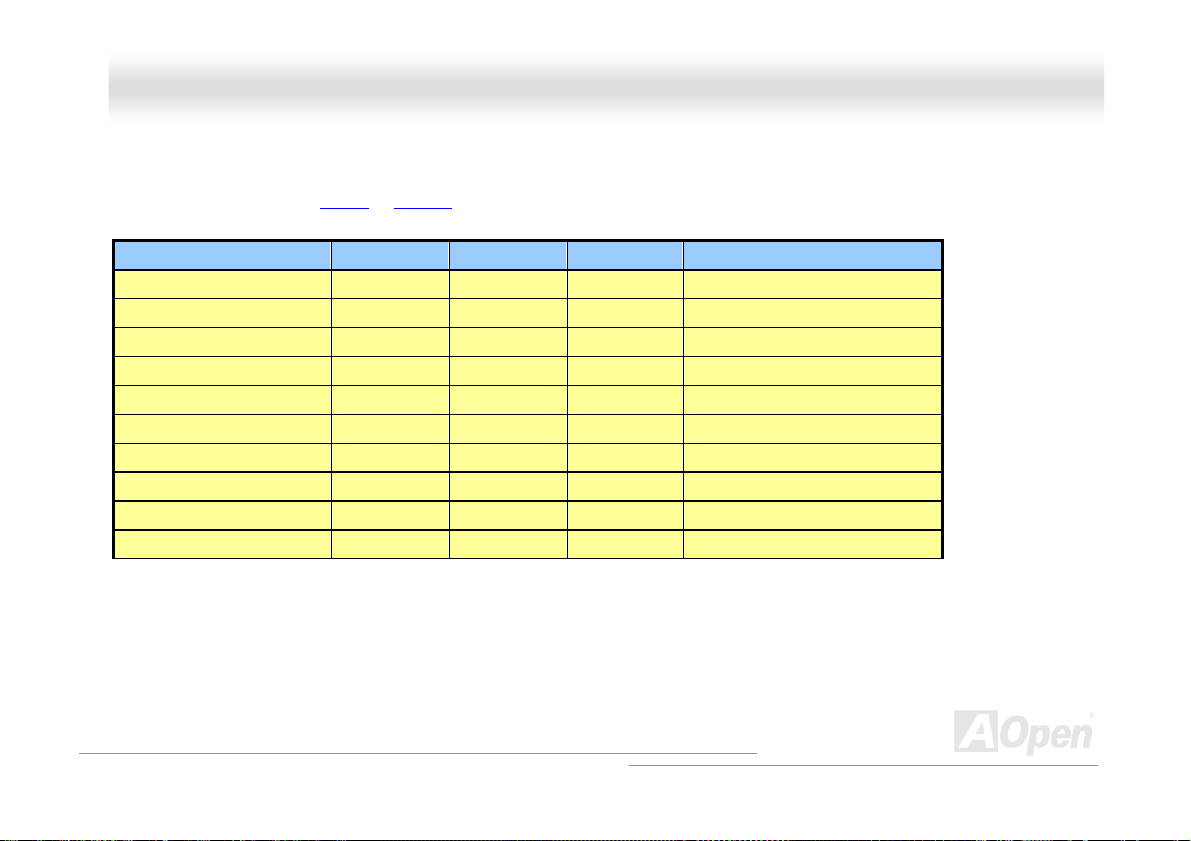
AATTAA110000 SSuuppppoorrtteedd
This motherboard supports ATA66 or ATA100 IDE devices. Following table lists the transfer rate of IDE PIO and DMA modes.
Mode Clock Period Clock Count Cycle Time Data Transfer Rate
PIO mode 0 30ns 20 600ns (1/600ns) x 2byte = 3.3MB/s
PIO mode 1 30ns 13 383ns (1/383ns) x 2byte = 5.2MB/s
PIO mode 2 30ns 8 240ns (1/240ns) x 2byte = 8.3MB/s
PIO mode 3 30ns 6 180ns (1/180ns) x 2byte = 11.1MB/s
PIO mode 4 30ns 4 120ns (1/120ns) x 2byte = 16.6MB/s
DMA mode 0 30ns 16 480ns (1/480ns) x 2byte = 4.16MB/s
DMA mode 1 30ns 5 150ns (1/150ns) x 2byte = 13.3MB/s
DMA mode 2 30ns 4 120ns (1/120ns) x 2byte = 16.6MB/s
DMA MODE3-4 (ATA 66) 30ns 2 60ns (1/60ns) x 2byte x2 = 66MB/s
DMA MODE5 (ATA 100) 20ns 2 40ns (1/40ns) x 2byte x2 = 100MB/s
28
Page 29
DDXXPPNN--UU OOnnlliinnee MMaannuuaall
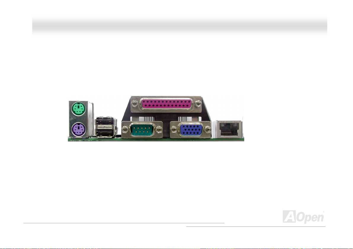
PPCC9999 CCoolloorr CCooddeedd BBaacckk PPaanneell
The onboard I/O devices are PS/2 Keyboard, PS/2 Mouse, COM1, VGA connector, Printer and USB2.0. The view
angle of drawing shown here is from the back panel of the housing.
PS/2 Mouse
Connector
USB2.0
Port
PS/2 Keyboard
Connector
PS/2 Keyboard: For standard keyboard, which is using a PS/2 plug.
PS/2 Mouse: For PC-Mouse, which is using a PS/2 plug.
USB Port: Available for connecting USB devices.
Parallel Port: To connect with SPP/ECP/EPP printer.
COM1: To connect with pointing devices, modem or others serial devices.
1GbE Ethernet Port: To connect RJ-45 Ethernet Cable.
VGA Connector: To connect monitor signal cable.
SPP/EPP/ECP Parallel Port
COM1 Port
VGA Connector
1 GbE
Ethernet
Port
29
Page 30
DDXXPPNN--UU OOnnlliinnee MMaannuuaall
CChhaassssiiss IInnttrruussiioonn SSeennssoorr
The “CASE OPEN” header provides chassis intrusion-monitoring function. This function will log an event in the system BIOS
when this header is connected. You can use the 2-pin chassis intrusion sensor to connect with this header, and enable the
chassis monitoring function of system BIOS.
Intruder
IDE LED
Spea ker
1
Power Switch
ACPI & Power LED
External NMI
Reset
30
Page 31

DDXXPPNN--UU OOnnlliinnee MMaannuuaall
JJPP11 CChheecckk PPaasssswwoorrdd JJuummppeerr
This motherboard provides check password function. You can use JP1 to enable or disable this function, which could prevent
your system from unauthorized invasion. The factory default setting is set to “Enable”(1-2), and you may disable this function by
setting the jumper to 2-3.
1
Password On (Default)
1
Password OFF
31
Page 32

DDXXPPNN--UU OOnnlliinnee MMaannuuaall
JJPP33 CClleeaarr CCMMOOSS JJuummppeerr
You can clear CMOS to restore system default setting. To clear the CMOS, follow the procedure below.
1. Turn off the system and unplug the AC power.
2. Remove ATX power cable from connector PWR2.
3. Locate JP3 and short pins 2-3 for a few seconds.
4. Return JP3 to its normal setting by shorting pin 1 & pin 2.
5. Connect ATX power cable back to connector PWR2.
1
Normal Operation
(default)
1
Clear CMOS
32
Page 33

DDXXPPNN--UU OOnnlliinnee MMaannuuaall
JJPP44 BBIIOOSS CCoonnffiigguurraattiioonn // RReeccoovveerryy SSeelleecctt JJuummppeerr
You can use JP4 to configure or recover your BIOS. The factory default setting is set to “Normal” (1-2), and you may configure
your BIOS bye by setting the jumper to 2-3, and recover your BIOS by removing the jumper.
1
Normal (default)
1
Recovery
1
Configure
33
Page 34

DDXXPPNN--UU OOnnlliinnee MMaannuuaall
SSuuppppoorrtt TTwwoo UUSSBB22..00 CChhaannnneellss ((FFoouurr PPoorrttss))
This motherboard provides two USB channels to link USB devices, such as mouse, keyboard, modem, printer, etc. There are
two connectors on the PC99 back panel. You can use proper cable to connect other USB connectors to the back panel or front
panel of chassis.
+5V
SBD2-
SBD2+
GND
KEY
1 2
+5V
SBD3-
SBD3+
GND
NC
34
Page 35

DDXXPPNN--UU OOnnlliinnee MMaannuuaall
SSuuppppoorrtt 11GGbbppss LLAANN oonnbbooaarrd
The Intel 82540 integrates Intel’s fourth-generation Gigabit MAC design with fully integrated, physical-layer circuitry to provide
a standard IEEE 802.3 Ethernet interface for 1000BASE-T and 100BASE-TX applications. The left green LED indicates the link
mode, it lights when linking to network and blinking when transferring data in 100Mbps mode. The right green LED indicates
the transfer mode, and it lights when data is transferring in 1Gbps mode.
d
Green/100
Green/1G
1GbE Ethernet Port
35
Page 36

DDXXPPNN--UU OOnnlliinnee MMaannuuaall
WWOOLL ((WWaakkee oonn LLAANN))
To use Wake On LAN function, you must have a network card with chipset that supports this feature, and connect a cable from
LAN card to motherboard WOL connector. The system identification information (probably IP address) is stored on network card
and because there is a lot of traffic on the Ethernet, you need to install network management software, such as ADM, for the
checking of how to wake up the system. Note that, at least 600mA ATX standby current is required to support the LAN card for
this function.
WOL connector
+5VSB
GND
LID
36
Page 37

DDXXPPNN--UU OOnnlliinnee MMaannuuaall
WOL Connector
(Motherboard Side)
Note: This picture is for example only; it may not exactly look the same with the motherboard you purchased.
WOL Connector
(Ethernet Card Side)
37
Page 38

DDXXPPNN--UU OOnnlliinnee MMaannuuaall
SSTTBBYY LLEEDD
STBY LED is AOpen’s considerate designs that we aim at providing you friendly system information. The STBY LED will light up
when power is provided to the motherboard. This is a convenient indication for you to check the system power status in many
circumstances such as power on/off, stand-by mode and RAM power status.
STBY LED
Warning: Do not install or
remove the DIMM module or
others devices when the STBY
38
Page 39

DDXXPPNN--UU OOnnlliinnee MMaannuuaall
RReesseettttaabbllee FFuussee
Traditional motherboard uses fuses to prevent Keyboard and USB port from over-current or shortage. These fuses are soldered
onboard that when it is broken (function to protect motherboard), user cannot replace them and result in malfunction of
motherboard.
With expensive Resettable Fuse, the motherboard can be resumed back to normal function even after the fuse had done its
protection job.
Resettable
Fuse
39
Page 40

DDXXPPNN--UU OOnnlliinnee MMaannuuaall
LLooww EESSRR CCaappaacciittoorr
The quality of low ESR capacitor (Low Equivalent Series Resistance) during high frequency operation is very important for
stability of CPU power. The location of where to put these capacitors is another know-how that requires experience and detail
calculation.
40
Page 41

DDXXPPNN--UU OOnnlliinnee MMaannuuaall
DDrriivveerr aanndd UUttiilliittyy
There are motherboard drivers and utilities included in AOpen Bonus CD. You don’t need to install all of them in order to boot
your system. But after you finish the hardware installation, you have to install your operation system first before you can install
any drivers or utilities. Please refer to your operation system’s installation guide.
41
Page 42

DDXXPPNN--UU OOnnlliinnee MMaannuuaall
BBIIOOSS SSeettuupp UUttiilliittyy
Most of system had already configured by the manufacturer or the dealer. There is no need to run
BIOS setup program when starting the computer unless you get a run setup program message.
The setup program loads configuration values into the battery-backed nonvolatile memory called
CMOS RAM. This memory area is not part of the system RAM.
42
Page 43

DDXXPPNN--UU OOnnlliinnee MMaannuuaall
If you repeatedly receive Run Setup messages, the battery
may be bad. In this case, the system cannot retain
configuration values in CMOS. Ask a qualified technician for
assistance.
The system will reboot immediately after you exit Setup.
EEnntteerriinngg SSeettuupp
To enter Setup, press the DELETE key.
You must press DELETE while the system is booting. This
key does not work during any other time.
The Setup Utility Main Menu appears:
43
Page 44

DDXXPPNN--UU OOnnlliinnee MMaannuuaall
The system supports two BIOS Utility levels: Basic and Advanced.
If you are an advanced user, you may want to check the detailed configuration of your system.
Detailed system configurations are contained in the Advanced Level. To view the Advanced Level,
press
.
44
Page 45

5
DDXXPPNN--UU OOnnlliinnee MMaannuuaall
The asterisk (*) mark indicates that the parameter appears
only when you are in the Advanced Level.
The parameters on the screens show default values.
These values may not be the same as those in your
system.
The grayed items on the screens have fixed settings and
are not user-configurable.
Use the arrow keys
Use
more than one page available.
Use
Press
to move to the next page or to return to the previous page if the setup screen has
, , “+” or “-” to select the options if they are available.
to return to the Main menu.
and to move around the Setup Utility screen.
4
Page 46

DDXXPPNN--UU OOnnlliinnee MMaannuuaall
SSyysstteemm IInnffoorrmmaattiioonn
The following screen appears if you select System Information from the Main menu:
46
Page 47

7
DDXXPPNN--UU OOnnlliinnee MMaannuuaall
The System Information menu shows the current basic configuration of your system.
The sections below explain the parameters.
Processor
The Processor parameter specifies the type of processor currently installed in your system. The
system supports Intel Xeon
TM
1.8 GHz above.
Processor Speed
The Processor Speed parameter specifies the speed of the processor currently installed in your
system.
Level 1 Cache
This parameter specifies the first-level or the internal fast accessed memory (i.e., the memory
integrated into the CPU) size, and whether it is enabled or disabled.
Level 2 Cache
This parameter specifies the second-level cache memory size that comes with the CPU. The
available cache size is 128 / 1024KB.
4
Page 48

DDXXPPNN--UU OOnnlliinnee MMaannuuaall
Floppy Drive A
This parameter specifies the system’s current diskette drive A settings.
Floppy Drive B
This parameter specifies the system’s current diskette drive B settings.
IDE Primary Channel Master
This parameter specifies the current configuration of the IDE device connected to the master port
of the primary IDE channel.
IDE Primary Channel Slave
This parameter specifies the current configuration of the IDE device connected to the slave port of
the primary IDE channel.
IDE Secondary Channel Master
This parameter specifies the current configuration of the IDE device connected to the master port
of the secondary IDE channel.
48
Page 49

DDXXPPNN--UU OOnnlliinnee MMaannuuaall
IDE Secondary Channel Slave
This parameter specifies the current configuration of the IDE device connected to the slave port of
the secondary IDE channel.
Total M emory
This parameter specifies the total amount of onboard memory. The memory size is automatically
detected by BIOS during the POST. If you install additional memory, the system automatically
adjusts this parameter to display the new memory size. Intel strongly commented the user using
double channel for DIMM plugged.
1st Bank/2nd Bank/3rd Bank/4th Bank
The 1st Bank, 2nd Bank, 3rd Bank, and 4th Bank parameters indicate the type and size of DRAM
installed in DIMM sockets 1, 2, 3 and 4 respectively. The “None” setting indicates that there is no
DRAM installed.
1st/2nd/3rd /4th Bank
Type and Size of DRAM installed in DIMM socket 1, 2, 3 and 4 respectively. The “None” setting
indicates that there is no DRAM installed.
49
Page 50

DDXXPPNN--UU OOnnlliinnee MMaannuuaall
Serial Port 1
This parameter shows the serial port 1 address and IRQ setting.
Serial Port 2
This parameter shows the serial port 2 address and IRQ setting.
Parallel Port
This parameter shows the parallel port address and IRQ setting.
PS/2 Mouse
The BIOS utility automatically detects if there is a pointing device connected to your system. If
there is, this parameter displays the “Installed” setting. Otherwise, this is set to “None”.
50
Page 51

DDXXPPNN--UU OOnnlliinnee MMaannuuaall
PPrroodduucctt IInnffoorrmmaattiioonn
The Product Information contains the general data about the system, such as the product name,
serial number, BIOS version, etc. This information is necessary for troubleshooting (may be
required when asking for technical support).
The following shows how the Product Information screen appears:
51
Page 52

DDXXPPNN--UU OOnnlliinnee MMaannuuaall
Product Name
This parameter specifies the official name of the system.
System S/N
This parameter specifies the system’s serial number.
Main Board ID
This parameter specifies the motherboard’s identification number.
System BIOS Version
This parameter specifies the version of the BIOS utility.
SMBIOS Version
This parameter specifies the version of the SMBIOS version.
52
Page 53

DDXXPPNN--UU OOnnlliinnee MMaannuuaall
DDiisskk DDeevviicceess
Select Disk Drives to input configuration values for disk drives.
The following screen shows the Disk Drives menu:
53
Page 54

DDXXPPNN--UU OOnnlliinnee MMaannuuaall
Floppy Drive A
To enter the configuration value for the first floppy drive, highlight the Floppy Drive A parameter.
Press
Drive A/Drive B
None
360KB 5.25"
1.2MB 5.25"
720KB 3.5"
1.44MB 3.5"
2.88MB 3.5"
Follow the same procedure to configure floppy drive B. Choose “None” if you do not have a second
floppy drive.
or
key to view the options and select the appropriate value.
,
These items select the floppy drive type. The available settings and
types supported by the motherboard are listed to the left.
54
Page 55

5
DDXXPPNN--UU OOnnlliinnee MMaannuuaall
IDE Drives
To configure the IDE drives connected to your system, select the parameter that represents the
channel and port where the desired hard disk to configure is connected. The options are:
IDE Primary Channel Master
This option lets you configure the hard disk drive connected to the master port of IDE channel 1.
5
Page 56

DDXXPPNN--UU OOnnlliinnee MMaannuuaall
IDE Primary Channel Slave
This option lets you configure the hard disk drive connected to the slave port of IDE channel 1.
56
Page 57

DDXXPPNN--UU OOnnlliinnee MMaannuuaall
IDE Secondary Channel Master
This option lets you configure the hard disk drive connected to the Master port of IDE channel 2.
57
Page 58

DDXXPPNN--UU OOnnlliinnee MMaannuuaall
IDE Secondary Channel Slave
This option lets you configure the hard disk drive connected to the Slave port of IDE channel 2.
58
Page 59

DDXXPPNN--UU OOnnlliinnee MMaannuuaall
The following screen appears if you select any of the IDE Drive parameters:
Device Detection Mode
Device Detection
Mode
Auto (Default)
User
None
If you select “Manual”, you need to fill in all remaining field, such as Cylinder,
Head, and Sector on this selected item. If the item “Auto” is selected, the
items will remain “0”. And when the system boot up, system will detect the
hard disk and configure it automatically. “None” means there is no device in
the channel.
Device Type
This parameter shows which type of IDE drive currently used.
Cylinder
This parameter specifies the number of cylinders of your hard disk, and is automatically set
depending on your Type parameter setting.
59
Page 60

DDXXPPNN--UU OOnnlliinnee MMaannuuaall
Head
This parameter specifies the number of heads of your hard disk, and is automatically set depending
on your Type parameter setting.
Sector
This parameter specifies the number of sectors of your hard disk, and is automatically set
depending on your Type parameter setting.
Size
This parameter specifies the size of your hard disk, in MB.
Hard Disk LBA Mode
Hard Disk Block
Mode
Auto (Default)
Disabled
This function enhances disk performance depending on the hard disk in
use. If you set this parameter to “Auto”, the BIOS utility automatically
detects if the installed hard disk drive supports the Block Mode function.
If supported, it allows data transfer in blocks (multiple sectors) at a rate
of 256 bytes per cycle. To disregard the feature, change the setting to
“Disable”.
60
Page 61

DDXXPPNN--UU OOnnlliinnee MMaannuuaall
OOnnbbooaarrdd PPeerriipphheerraallss
The Onboard Peripherals Configuration allows you to configure the onboard communication ports
and the onboard devices. Selecting this option displays the following screen:
61
Page 62

DDXXPPNN--UU OOnnlliinnee MMaannuuaall
Serial Ports 1 and 2
Serial Port 1 & 2
Enabled (Default)
Disabled
Base Address
Base Address
Serial Port 1:
3F8h (Default)
3E8h
2E8h
Serial Port 2:
2F8h (Default)
2E8h
3E8h
These parameters allow you to enable or disable serial
ports 1 and 2.
This item allows you to assign address and interrupt for the
board serial port.
62
Page 63

DDXXPPNN--UU OOnnlliinnee MMaannuuaall
IRQ
IRQ
Serial Port 1:
4 (Default), 11
Serial Port 2:
3 (Default), 10
This function lets you assign an interrupt for serial ports 1
and 2. The options for serial ports 1 are IRQ 4 and 11. The
options for serial port 2 are IRQ 3 and 10.
The Base Address and IRQ parameters for each port are
configurable only if the port is enabled.
Parallel Port
Parallel Port
Enabled (Default)
Disabled
This parameter allows you to enable or disable the parallel
port.
63
Page 64

DDXXPPNN--UU OOnnlliinnee MMaannuuaall
Base Address
Base Address
378h (Default)
3BCh
278h
IRQ
IRQ
7 (Default), 5
This item allows you to assign address and interrupt for the
board serial port.
This function lets you assign an interrupt for the parallel
port. The options are IRQ 5 and 7.
The Base Address and IRQ parameters are configurable only if
Parallel Port is enabled.
If you install an add-on card that has a parallel port whose
address conflicts with the onboard parallel port, a warning
appears on the screen.
Check the parallel port address of the add-on card and change
64
Page 65

5
DDXXPPNN--UU OOnnlliinnee MMaannuuaall
the address to one that does not conflict.
Operation Mode
Operation Mode
EPP (Default)
Bi-Directional
Standard
ECP
Setting Function
Standard Parallel Port (Standard) Allows normal speed one-way operation
Bi-directional Parallel Port
(Bi-directional)
Enhanced Parallel Port (EPP) Allows bi-directional parallel port operation at
This item lets you set the parallel port mode. The mode
options are Standard, Bi-directional, EPP (Enhanced Parallel
Port) and ECP (Extended Parallel Port).
Allows normal speed operation in a two-way
mode
maximum speed
6
Page 66

DDXXPPNN--UU OOnnlliinnee MMaannuuaall
Setting Function
Extended Capabilities Port (ECP) Allows parallel port to operate in
bi-directional mode and at a speed higher
than the maximum data transfer rate
ECP DMA Channel
ECP Mode Use DMA
3
1 (Default)
PS/2 Mouse Controller
PS/2 Mouse
Controller
Enabled (Default)
Disabled
This item becomes active only if you select Extended
Capabilities Port (ECP) as the operation mode. It allows you
to assign DMA channel 1 or DMA channel 3 for the ECP
parallel port function (as required in Windows 95).
This parameter enables or disables the onboard PS/2 mouse
controller.
66
Page 67

7
DDXXPPNN--UU OOnnlliinnee MMaannuuaall
USB Host Controller
USB Host
Controller
Enabled (Default)
Disabled
USB Legacy Mode
USB Legacy Mode
Enabled
Disabled (Default)
Onboard Ethernet Chip
On-board
Ethernet Chip
Enabled (Default)
Disabled
This parameter lets you enable or disable the USB controller on
board. When enabled, it activates the USB function of the
system. When disabled, it deactivates the function.
This parameter lets you enable or disable the USB controller on
board. When enabled, it activates the USB function of the
system. When disabled, it deactivates the function.
This parameter allows you to enable or disable the onboard
network feature.
6
Page 68

DDXXPPNN--UU OOnnlliinnee MMaannuuaall
PPoowweerr MMaannaaggeemmeenntt
The Power Management menu allows you to configure the system power-management feature.
The following screen shows the Power Management parameters and their default settings:
68
Page 69

DDXXPPNN--UU OOnnlliinnee MMaannuuaall
A parameter with an asterisk (*) mark indicates that the
parameter appears only when you are using in the Advanced
Level. See “Entering Setup” on Page
Power Management Mode
Power
Management
Mode
Enabled (Default)
Disabled
This parameter allows you to reduce power consumption.
When this parameter is set to “Enabled”, you can configure the
IDE hard disk and system timers. Setting it to “Disabled”
deactivates the power-management feature and its timers.
69
Page 70

DDXXPPNN--UU OOnnlliinnee MMaannuuaall
IDE Hard Disk Standby Timer
IDE Hard Disk
Standby Timer
Off (Default)
1 to 15min
System Sleep Timer
System Sleep
Timer
Off (Default)
120, 110, 100…20,
15, 10, 5, 2min
This parameter allows the hard disk to enter standby mode after
inactivity of 1 to 15 minutes, depending on your setting. When
you access the hard disk again, allow 3 to 5 seconds (depending
on the hard disk) for the disk to return to normal speed. Set this
parameter to “Off” if your hard disk does not support this
function.
This parameter sets the system to the lowest power-saving
mode after a specified period of inactivity. Any keyboard or
mouse action or any activity detected from the IRQ channels
resumes system operation.
70
Page 71

DDXXPPNN--UU OOnnlliinnee MMaannuuaall
Sleep Mode
Sleep Mode
Standby
Suspend (Default)
This parameter lets you specify the power-saving mode that the
system will enter after a specified period of inactivity. The options
are “Standby” and “Suspend” modes. This parameter becomes
configurable only if the System Sleep Timer is enabled. Any
keyboard or mouse action, or any enabled monitored activities
occurring through the IRQ channels resume system operation.
Power Switch < 4 sec.
Power Switch < 4
Sec.
Suspend
Power Off (Default)
When set to ”Power Off”, the system automatically turns off
when the power switch is pressed for less than 4 seconds. When
set to ”Suspend”, the system enters the suspend mode when
pressed for less than 4 seconds.
71
Page 72

DDXXPPNN--UU OOnnlliinnee MMaannuuaall
System Wake-up Event
The system wake-up event allows the system to resume operation when the modem ring indicator
is enabled.
Modem Ring Indicator
Modem Ring
Indicator
Enabled (Default)
Disabled
PCI Power Management
PCI Power
Management
Enabled (Default)
Disabled
When “Enabled” any fax/modem activity wakes up the system
from suspend mode. The default setting is “Enabled”.
This item allows you to enable or disable the PCI power
management function.
72
Page 73

DDXXPPNN--UU OOnnlliinnee MMaannuuaall
RTC Alarm
RTC Alarm
Enabled
Disabled (Default)
Resume Day
Resume Day
1 to 31
Resume Time
Resume Time
Hh:mm:ss
This item allows you to set a certain time on a certain day to
wake-up the system from suspend mode.
This item is displayed when you enable the “RTC Timer” option.
Here you can specify what date you want to wake up the system.
For example, setting to 15, the system will wake up on the 15
day of every month.
This item is displayed when you enable the RTC Wake Up Timer
option. Here you can specify what time you want to wake up the
system.
th
73
Page 74

DDXXPPNN--UU OOnnlliinnee MMaannuuaall
Restart On AC/Power Failure
Restart On
AC/Power Failure
Enabled (Default)
Disabled
Pre-State
When “Enabled”, the system automatically turns on when the
power comes back. When “Disabled” the system turns off and
does not turn on when the power comes back. When set to
“Pre-State”, the system maintains the last power state when the
power comes back.
74
Page 75

DDXXPPNN--UU OOnnlliinnee MMaannuuaall
BBoooott OOppttiioonnss
This option allows you to specify your preferred setting for boot up.
The following screen appears if you select Boot Options from the Basic Configuration menu:
75
Page 76

DDXXPPNN--UU OOnnlliinnee MMaannuuaall
Boot Sequence
This parameter allows you to specify the boot search sequence during POST.
st
. The system checks this drive first.
z 1
nd
. The system then checks this drive if it can not boot from the 1st specified drive.
z 2
rd
. If the 1st and 2nd searches fail then it boots from this drive.
z 3
th
. If the 1st, 2nd, and 3rd searches fail then it boots from this drive.
z 4
BIOS will display an error message if the drive(s) specified is not bootable.
Hyper-Threading Technology
Hyper-Threading
Technology
Enable (Default)
Disabled
This parameter allows the system to use hyper-threading
technology.
76
Page 77

7
DDXXPPNN--UU OOnnlliinnee MMaannuuaall
Fast Boot
Fast Boot
Auto (Default)
Disabled
Silent Boot
Silent Boot
Enabled (Default)
Disabled
This parameter allows the system to boot faster by skipping
some POST routines.
This parameter enables or disables the Silent Boot function.
When set to ”Enabled”, BIOS is in graphical mode and displays
only an identification logo during POST and while booting. After
booting the screen displays the operating system prompt (such
as DOS) or logo (such as Windows 95). If any error occurs while
booting, the system automatically switches to the text mode.
Even if your setting is ”Enabled”, you may also switch to the text
mode while booting by pressing
DELETE key to enter setup” message on the screen.
When set to “Disabled”, BIOS is in the conventional text mode
where you see the system initialization details on the screen.
7
when you see the “Press
Page 78

DDXXPPNN--UU OOnnlliinnee MMaannuuaall
Num Lock After Boot
Num Lock After
Boot
Enabled (Default)
Disabled
This parameter allows you to activate the Num Lock function
upon booting.
Memory Test
Memory Test
Enabled
Disabled (Default)
When set to ”Enabled”, this parameter allows the system to
perform a RAM test during the POST routine. When set to
“Disabled”, the system detects only the memory size and
bypasses the test routine.
Boot From LAN Desk (R) Service Agent
Boot From LAN
Desk(R) Service
Agent
Enabled
Disabled (Default)
When set to “Enabled”, this parameter allows system to boot
from LAN Desk (R) Service Agent.
78
Page 79

DDXXPPNN--UU OOnnlliinnee MMaannuuaall
DDaattee aanndd TTiimmee
The real-time clock keeps the system date and time. After setting the date and time, you do not
need to enter them every time you turn on the system. As long as the internal battery remains good
(approximately seven years) and connected, the clock continues to keep the date and time
accurately even when the power is off.
Date
Date
ww:mm:dd:yy
Valid values for weekday, month, day, and year are:
Highlight the items on the Date parameter and press
to set the date following the weekday-month-day-year
format.
or
79
Page 80

DDXXPPNN--UU OOnnlliinnee MMaannuuaall
z Weekday: Sun, Mon, Tue, Wed, Thu, Fri, Sat
z Month: Jan, Feb, Mar, Apr, May, Jun, Jul, Aug, Sep, Oct, Nov, Dec
z Day: 1 to 31
z Year: 1980 to 2079
Time
Time
hh:mm:ss
Valid values for hour, minute, and second are:
z Hour 00 to 23
z Minute 00 to 59
z Second 00 to 59
Highlight the items on the Time parameter and press
to set the time following the hour-minute-second format.
80
or
Page 81

DDXXPPNN--UU OOnnlliinnee MMaannuuaall
SSyysstteemm SSeeccuurriittyy
The Setup program has a number of security features to prevent unauthorized access to the
system and its data.
The following screen appears if you select System Security from the Main menu:
81
Page 82

DDXXPPNN--UU OOnnlliinnee MMaannuuaall
Supervisor Password
Supervisor
Password
None (Default)
Present
1. Enable the Supervisor Password parameter in the System Security menu by pressing the
ENTER key. The Supervisor Password windows will appear as shown above.
2. Type a password. The password may consist of up to seven characters.
3. Press the ENTER key. Re-type the password to verify your first entry then press ENTER key
again.
4. Highlight the “Set or change password” option and press ENTER key.
5. Press the ESC key to return the System Security screen.
6. Press the ESC key to exit setup. The Exit Setup screen will appear.
This item can prevent unauthorized access to the BIOS utility.
The “Present” setting allows you to set a setup password.
Be very careful when typing your password because the
actual characters do not appear on the screen.
82
Page 83

DDXXPPNN--UU OOnnlliinnee MMaannuuaall
7. Choose “Yes” to save your setting and exit Setup. Your password will be saved to CMOS.
8. If you want to remove the password, please select “Disabled” to disable this function.
User Password
User Password
None (Default)
Present
This item can secure your system against unauthorized use.
Once you set this password, you have to type it whenever you
boot the system. This item is available when only Supervisor
Password is set.
Disk Drive Controller
The disk drive control features allow you to control the floppy drive or the hard disk drive boot
function to prevent loading operating systems or other programs from a certain drive while the
other drives are operational (under DOS mode only).
The table below lists the drive control settings and their corresponding functions.
Floppy Drive
Setting Description
Normal Floppy drive functions normally
83
Page 84

DDXXPPNN--UU OOnnlliinnee MMaannuuaall
Write Protect All Sectors Disables the write function on all
sectors
Write Protect Boot Sector Disables the write function only on the
boot sector
Hard Disk Drive
Setting Description
Normal Hard disk drive functions normally
Write Protect All Sectors Disables the write function on all
sectors
Write Protect Boot Sector Disables the write function only on the
boot sector
84
Page 85

5
DDXXPPNN--UU OOnnlliinnee MMaannuuaall
HHeeaalltthh MMoonniittoorr SSttaattuuss
As you turn on your system, the health monitor status will continue to monitor your system’s
working voltage, fan status and CPU temperature. Selecting the option displays the following
screen:
8
Page 86

DDXXPPNN--UU OOnnlliinnee MMaannuuaall
LLooaadd DDeeffaauulltt SSeettttiinnggss
Use this option to load the default settings for the optimized system configuration. When you load
the default settings, some of the parameters are grayed-out with their fixed settings. These grayed
parameters are not user-configurable.
The following dialog box appears when you select Load Default Settings from the main menu:
Select “Yes” to load the default settings.
Select “No” to ignore the message and return to the BIOS utility.
86
Page 87

DDXXPPNN--UU OOnnlliinnee MMaannuuaall
AAbboorrtt SSeettttiinnggss CChhaannggee
Use this option to disregard your changes to the BIOS and reload your previous settings.
The following dialog box appears when you select Abort Settings Change from the main menu:
Select “Yes” to disregard your changes and reload your previous settings. After reload, the main
menu appears on screen.
Select “No” to ignore the message and return to the BIOS utility.
87
Page 88

DDXXPPNN--UU OOnnlliinnee MMaannuuaall
GGlloossssaarryy
AACC9977 CCOODDEECC
Basically, AC97 CODEC is the standard structure of PCI sound card. As we know, computer is digital-based, but music is based
on analog-based. Therefore, there must be a process to turn digital into analog during the last stage processing of sound in
computer. Hence, the component on sound card that play this important task is what we called CODEC.
Audio CODEC 97 (briefly called AC97) is the specification regulated by Intel, and it’s about the structure of audio conversion.
The special place about CODEC is that it is separated from sound card (CODEC is an independent chipset). Therefore, PCI
sound card could possess with 90db and do other application process as well. We called CODEC that meets this structure AC97
CODEC.
AACCPPII ((AAddvvaanncceedd CCoonnffiigguurraattiioonn && PPoowweerr IInntteerrffaaccee)
ACPI is the power management specification of PC97 (1997). It intends to save more power by taking full control of power
management to operating system and bypass BIOS
to operating system (such as Windows 98). This is a bit similar as the PnP
power switch to control the power state transition.
AACCRR ((AAddvvaanncceedd CCoommmmuunniiccaattiioonn RRiisseerr)
Building on the PC motherboard riser architecture, ACR slot is backward compatible with AMR but beyond the limitation of it.
The ACR specification is designed to support modem, audio, Local Area Network (LAN) and Digital Subscriber Line (DSL).
)
. The chipset or super I/O chip needs to provide standard register interface
register interface. ACPI defines ATX momentary soft
)
88
Page 89

DDXXPPNN--UU OOnnlliinnee MMaannuuaall
)
AAGGPP ((AAcccceelleerraatteedd GGrraapphhiicc PPoorrtt)
The main function of AGP simply put is to tell monitor what screen information had to be shown, a visual transmission device
actually. With the rapid developing of AGP card, we can see that it had been developed from single colorful AGP card to 2D and
3D graphic. AGP supports only memory read/write operation and single-master single-slave one-to-one only. Though AGP and
PCI share the same algorithm of 32-bit, its frequencies are 66MHz and 33MHz respectively. AGP interface had been
developed from 2X to 8x.
1X AGP, data transfer rate is 66MHz x 4byte x 1 = 264MB/s
2X AGP, data transfer rate is 66MHz x 4byte x 2 = 528MB/s
4X AGP, data transfer rate is 66MHz x 4byte x 4 = 1056MB/s.
8X AGP, data transfer rate is 66MHz x 4byte x 8 = 2112MB/s.
AAMMRR ((AAuuddiioo//MMooddeemm RRiisseerr)
The CODEC circuit of AC97 sound/modem solution can be put on motherboard or put on a riser card (AMR card) that connects
to motherboard through AMR connector.
)
AATTAA ((AATT AAttttaacchhmmeenntt)
Before talking about ATA (AT Attachment), we must understand DMA (Direct Memory Access), which allows devices to skip the
CPU devices and access memory directly. DMA specification could not only eliminate the workload of CPU, but also accelerate
the transmission of data. DMA begins with a data transfer rate of 16.6MB/Sec, but afterward developed to new data rate of
33.3MB/Sec, which is twice the data rate and we called it Ultra DMA. ATA details power and data signals between the drive
)
89
Page 90

DDXXPPNN--UU OOnnlliinnee MMaannuuaall
and integrated drive controller and the computer's motherboard. Two drives (master and slave) are supported. The ATA
specification allows the drive to connect directly to the ISA bus on the computer. ATA transfer rate then had been developed to
133MHz/Sec and would come out with fastest rate later (please refer to Serial ATA
DMA, data transfer rate is 16.6MHz/s.
Ultra DMA, data transfer rate is 16.6MHz x 2 = 33MB/s.
ATA/6 6, data transfer rate is 16.6MHz x 4 = 66MB/s.
ATA/100, data transfer rate is 16.6MHz x 6 = 100MB/s.
ATA/133, data transfer rate is 16.6MHz x 8 = 133MB/s.
(ATA/133 uses both rising edge and falling edge as ATA/66 but clock cycle time is reduced to 30ns.)
)
BBIIOOSS ((BBaassiicc IInnppuutt//OOuuttppuutt SSyysstteemm)
BIOS, is a set of assembly routine/program that reside in EPROM or Flash ROM. BIOS controls Input/output devices and other
hardware devices of motherboard. In general, to provide hardware independent portability, operation system and drivers is
required to access BIOS without directly access hardware devices.
h
BBlluueettooootth
Bluetooth is a wireless transferring technology that enables short-range wireless connections between desktop and laptop
computers, personal digital assistants (PDAs), cellular phones, printers, scanners, digital cameras and even home
appliances. The principle of Bluetooth (a chipset) is to transfer information and voices at the frequency of ISM Band. Every
Bluetooth technology devices do come with a standard address for you to connect one-to-one or one-to-seven (to form a
Pico-net), with transferring range up to 10 meters (100 meters to follow), using low power radio. Bluetooth do not only possess
).
90
Page 91

DDXXPPNN--UU OOnnlliinnee MMaannuuaall
high transfer rate of 1MB/s, it also could be encrypted with pin code. With hopping rate of 1600 hops per second, it’s difficult to
be intercepted and are less interrupted by electromagnetic wave.
)
CCNNRR ((CCoommmmuunniiccaattiioonn aanndd NNeettwwoorrkkiinngg RRiisseerr)
The CNR specification provides the PC industry the opportunity to deliver a flexible and cost reduced method of implementing
LAN, home networking, DSL, USB, wireless, audio and modem subsystems widely used in today's "connected PCs". The CNR
specification is an open industry specification and is supported by OEMs, IHV card manufacturers, silicon supplier and
Microsoft.
M
DDDDRR ((DDoouubbllee DDaattaa RRaattee)) RRAAM
DDR RAM utilizes the existing SDRAM (For ex, PC-100, PC-133) infrastructure and technology while doubling the nominal
bandwidth available to systems in an easy to design and simple to adopt way. Based on FSB frequency, DDR RAM on the
market are DDR200, DDR266 and DDR333 with more coming around soon.
DDR200, transfer bandwidth up to 200x64/8=1600MB/s (PC1600)
DDR266, transfer bandwidth up to 266x64/8=2100MB/s (PC2100)
DDR333, transfer bandwidth up to 333x64/8=2700MB/s (PC2700)
DDR400, transfer bandwidth up to 400x64/8=3200MB/s (PC3200)
91
Page 92

DDXXPPNN--UU OOnnlliinnee MMaannuuaall
EECCCC ((EErrrroorr CChheecckkiinngg aanndd CCoorrrreeccttiioonn))
The ECC mode needs 8 ECC bits for 64-bit data. Each time memory is accessed; ECC bits are updated and checked by a
special algorithm. The ECC algorithm has the ability to detect double-bit error and automatically correct single-bit error while
parity mode can only detect single-bit error.
EEEEPPRROOMM ((EElleeccttrroonniicc EErraassaabbllee PPrrooggrraammmmaabbllee RROOMM)
Also known as E2PROM. Both EEPROM and Flash ROM can be re-programmed by electronic signals, but the interface
technology is different. Size of EEPROM is much smaller than flash ROM.
EEPPRROOMM ((EErraassaabbllee PPrrooggrraammmmaabbllee RROOMM)
Traditional motherboard stores BIOS code in EPROM. EPROM can only be erased by ultra-violet (UV) light. If BIOS has to be
upgraded, you need to remove EPROM from motherboard, clear by UV light, re-program, and then insert back.
s
EEVV66 BBuus
EV6 Bus is the technology of Alpha processor from Digital Equipment Corporation. EV6 bus uses both rising and falling clock
edge to transfer data, similar as DDR RAM or ATA/66 IDE bus.
EV6 Bus Speed = CPU external bus clock x 2.
200 MHz EV6 bus, 200MHz = 100 MHz external bus clock x 2
)
)
92
Page 93

DDXXPPNN--UU OOnnlliinnee MMaannuuaall
FFCCCC DDooCC ((DDeeccllaarraattiioonn ooff CCoonnffoorrmmiittyy)
The DoC is component certification standard of FCC EMI regulations. This standard allows DIY component (such as
motherboard) to apply DoC label separately without a shielding of housing.
)
)
FFCC--PPGGAA ((FFlliipp CChhiipp--PPiinn GGrriidd AArrrraayy)
FC means Flip Chip, FC-PGA is a package of Intel for Pentium III for 0.18µm process CPU, which can be plugged into SKT370
socket.
FFCC--PPGGAA22 ((FFlliipp CChhiipp--PPiinn GGrriidd AArrrraayy)
After FC-PGA, FC-PGA2 is the package for 0.13µm process CPU developed by Intel, which can be plugged into SKT423/478
socket as well.
M
FFllaasshh RROOM
Flash ROM can be re-programmed by electronic signals. It is easier for BIOS to upgrade by a flash utility, but it is also easier to
be infected by virus. Because of increase of new functions, BIOS size is increased from 64KB to 512KB (4M bit).
HHyyppeerr TThhrreeaaddiinng
Hyper-Threading technology is an innovative design from Intel that enables multi-threaded software applications to process
threads in parallel within each processor resulting in increased utilization of processor execution resources. As a result, an
average improvement of ~40% in CPU resource utilization yields higher processing throughput.
g
)
93
Page 94

DDXXPPNN--UU OOnnlliinnee MMaannuuaall
4
IIEEEEEE 1133994
IEEE 1394, which also called Firewire, is a serial data transfer protocol and interconnection system. The main feature of the
Firewire that assures its adoption for the digital video and audio (A/V) consumer application is its low cost. Fire wire interface is
capable of supporting various high-end digital A/V applications, such as consumer A/V device control and signal routing, Digital
Video (DV) editing, home networking, and more than 32 channels of digital mixing. Gone are those days of expensive video
capture cards. Firewire allows for video capture from both newer DV camcorders with Firewire ports and older analog
equipment using A/V to Firewire converters.
The advantages of the IEEE1394:
High data transfer rate – Start from 400 Mbps, (with 800/1600/3200 Mbps coming soon), which is about 30 times faster than
USB 1.1.
Supports up to 63 devices (16 - daisy chained) with cable length up to about 4.5 m (14 feet).
Hot-pluggable (like USB). No need to turn of your device to connect or disconnect, and you don't need to reboot your PC. Also,
it is a plug-and-play bus.
IEEE1394 is very easy to connect (Like USB1.1/2/0).
PPaarriittyy BBiit
The parity mode uses 1 parity bit for each byte, normally it is even parity mode, that is, each time the memory data is updated,
parity bit will be adjusted to have even count "1" for each byte. When next time, if memory is read with odd number of "1", the
parity error is occurred and this is called single bit error detection.
t
94
Page 95

DDXXPPNN--UU OOnnlliinnee MMaannuuaall
PPCCII ((PPeerriipphheerraall CCoommppoonneenntt IInntteerrffaaccee)) BBuus
Developed by Intel, Peripheral Component Interconnect (PCI) is a local bus standard. A bus is a channel used to transfer data to
(input) and from (output) a computer and to or from a peripheral device. Most PCs have a PCI bus usually implemented at
32-bits providing a 33 MHz clock speed with a throughput rate of 133 MBps.
t
PPDDFF FFoorrmmaat
With PDF file, it is easy to do universal document exchange. Virtually any document may be converted in Portable Document
Format (PDF). Contents in PDF documents are exactly the same as the original file, including fonts and graphics, and they can
be distributed by e-mail or stored on the World Wide Web, an intranet, a file system, or a CD-ROM for other users to view on
any platforms. You may download Acrobat Reader in order to read PDF file from its website (www.adobe.com
PPnnPP ((PPlluugg aanndd PPllaayy)
Oversimplified, Plug-and-Play automatically tells the software (device drivers) where to find various pieces of hardware (devices)
such as modems, network cards, sound cards, etc. Plug-and-Play's task is to match up physical devices with the software
(device drivers) that operates them and to establish channels of communication between each physical device and its driver.
PPOOSSTT ((PPoowweerr--OOnn SSeellff TTeesstt)
The BIOS self-test procedure after power-on, sometimes, it is the first or the second screen shown on your monitor during
system boot.
)
)
s
).
95
Page 96

DDXXPPNN--UU OOnnlliinnee MMaannuuaall
PPSSBB ((PPrroocceessssoorr SSyysstteemm BBuuss)) CClloocck
PSB Clock means the external bus clock of CPU.
CPU internal clock = CPU PSB Clock x CPU Clock Ratio
RRDDRRAAMM ((RRaammbbuuss DDyynnaammiicc RRaannddoomm AAcccceessss MMeemmoorryy)
A DRAM technology developed by Rambus Corporation*, to achieve high speed of memory through the use of multiple channels
in parallel by 16-bits. Basically, RDRAM uses new structure of Multibank, which is quite different from FPM, EDO, SDRAM.
Using different memory module as well, RDRAM uses “RIMM” with transfer rate of 600/700/800MHz, providing bandwidth as
high to 1.6GB.
RRIIMMMM ((RRaammbbuuss IInnlliinnee MMeemmoorryy MMoodduullee)
184-pin memory module that supports RDRAM memory technology. A RIMM memory module may contain up to maximum of 16
RDRAM devices.
SSDDRRAAMM ((SSyynncchhrroonnoouuss DDRRAAMM))
SDRAM is one of the DRAM technologies that allow DRAM to use the same clock as the CPU host bus (EDO and FPM are
asynchronous and do not have clock signal). It is similar as PBSRAM to use burst mode transfer. SDRAM comes in 64-bit
168-pin DIMM and operates at 3.3V, and have been gradually replaced by DDR RAM.
k
)
)
96
Page 97

DDXXPPNN--UU OOnnlliinnee MMaannuuaall
SSAATTAA ((SSeerriiaall AATTAA)
The Serial ATA specification is designed to overcome speed limitations while enabling the storage interface to scale with the
growing media rate demands of PC platforms. Serial ATA is to replace parallel ATA
systems and drivers, adding performance headroom for years to come. It is developed with data transfer rate of 150
Mbytes/second, and 300M/bs, 600M/bs to come. It reduces voltage and pins count requirements and can be implemented with
thin and easy to route cables.
SSMMBBuuss ((SSyysstteemm MMaannaaggeemmeenntt BBuuss)
SMBus is also called I2C bus. It is a two-wire bus developed for component communication (especially for semiconductor IC).
For example, set clock of clock generator for jumper-less motherboard. The data transfer rate of SMBus is only 100Kbit/s, it
allows one host to communicate with CPU and many masters and slaves to send/receive message.
SSPPDD ((SSeerriiaall PPrreesseennccee DDeetteecctt)
SPD is a small ROM or EEPROM device resided on the DIMM or RIMM. SPD stores memory module information such as DRAM
timing and chip parameters. SPD can be used by BIOS
UUSSBB 22..00 ((UUnniivveerrssaall SSeerriiaall BBuuss)
A Universal Serial Bus (USB) is an external bus (an interconnection) standard that supports data transfer rates of 12 Mbps. A
single USB port can be used to connect up to 127 peripheral devices, such as mouse, modems and keyboards. Introduced in
1996, USB has completed replaced serial and parallel ports. It also supports plug-and-play installations and hot plugging
Plug-and-play is the ability to add and remove devices to a computer while the computer is running and have the operating
)
with the compatibility with existing operating
)
)
to decide best timing for this DIMM or RIMM.
)
97
Page 98

DDXXPPNN--UU OOnnlliinnee MMaannuuaall
system automatically recognize the change. USB 2.0, which supports data transfer rates of 480 Mbps, has been widely used in
motherboard these days.
)
VVCCMM ((VViirrttuuaall CChhaannnneell MMeemmoorryy)
NEC’s Virtual Channel Memory (VCM) is a new DRAM core architecture that dramatically improves the memory system’s ability
to service multimedia requirements. VCM increases memory bus efficiency and performance of any DRAM technology by
providing a set of fast static registers between the memory core and I/O pins. Using VCM technology results in reduced data
access latency and reduced power consumption.
WWiirreelleessss LLAANN –– 880022..1111b
802.11 is a specification developed by IEEE and Wireless LAN technology, which is an interface between a wireless client and a
base station or between two wireless clients.
802.11 family includes the following specifications and with more coming:
802.11 = 1 or 2 Mbps transmission in the 2.4 GHz band, using either frequency hopping spread spectrum (FHSS) or direct
sequence spread spectrum (DSSS)).
802.11a = 54 Mbps in the 5GHz band, using orthogonal frequency division multiplexing)
802.11b (11 Mbps transmission in the 2.4 GHz band, using direct sequence spread spectrum (DSSS).
e
ZZIIPP ffiille
A compressed file format to reduce file size. To unzip file, run shareware PKUNZIP (http://www.pkware.com/) for DOS and other
operating system or WINZIP (http://www.winzip.com/
b
) for windows environment.
98
Page 99

DDXXPPNN--UU OOnnlliinnee MMaannuuaall
TTrroouubblleesshhoooottiinngg
If you encounter any trouble to boot you system, follow the procedures accordingly to resolve the problem.
Note: If using some DIMMs beyond available list, press F10 key
when power on, may solve some DIMMs issues.
Start
Turn off the power and unplug the AC power cable, then remove all of the add-on
cards and cables, including VGA, IDE, FDD, COM1, COM2 and printer.
Next
99
Page 100

DDXXPPNN--UU OOnnlliinnee MMaannuuaall
Then connect your monitor and keyboard.
Next
Turn on the power
and check if the power
supply and CPU fan work
properly.
No Yes
The problem is probably caused by
power supply or motherboard failure
Please contact your reseller or local
distributor for repairing.
.
100
 Loading...