

Page 1

y
y
A
pp
ortress 9500/9300
DOC. NO. : DX3RPU-OL-E0201A
Instruction
Housing
Installation
Hardware
BIOS Setup
Utilit
SCSISelect™
Utilit
Technical su
Glossary &
Open
1
ort
Page 2

A
Copyright© 2000 AOpen Incorporated
All Rights Reserved.
AOpen Fortress 9500/9300
User’s Guide
Changes may be made periodically to the information in this publication without obligation to notify
any person of such revision or changes. Such changes will be incorporated in new editions of this
manual or supplementary documents and publications. This company makes no representations or
warranties either expressed or implied, with respect to the contents hereof and specifically
disclaims the im plied warranties of merchantability or fitness for a particular purpose.
No part of this publication may be reproduced., st ored in a retrieval system, or transm itted, in any
form or by any means, electronic, mechanical, photocopy, recording, or otherwise, without the prior
written permission of AOpen Incorporated.
All brand and product names mentioned in this manual are trademarks and/or registered
trademarks of their respective companies.
2
Open
Page 3

A
IImmppoorrttaanntt SSaaffeettyy IInnssttrruuccttiioonnss
1. Read these instructions carefully. Save these instructions for future reference.
2. Follow all warnings and instructions marked on the product.
3. Do not use this product near water.
4. Do not place this product on an unstable cart, stand, or table. The product may fall, causing
serious damage to the product.
5. Slots and openings in the cabinet and the back or bottom are provided for ventilation; to
ensure reliable operation of the product and to protect it from overheating, these openings
must not be blocked or covered. The openings should never block by placing the product on a
bed, sofa, rug, or other similar surface. This product should never be placed near or over a
radiator or heat register, or in a built-in installation unl ess proper ventilation is provided.
6. This product should be operated from the type of power indicated on the marking label. If
you are not sure of the type of power available, consult your dealer or local power company.
7. This product is equipped with a 3-wire grounding-type plug, a plug having a third (grounding)
pin. This plug will only fit into a grounding-type power outlet. This is a safety feature. If you are
unable to insert the plug into the outlet, contact your electrician to replace your obs olete outlet.
Do not defeat the purpose of the grounding-t ype plug.
8. Do not allow anything to res t on t he power cord. Do not locate t his product where persons will
3
Open
Page 4

A
walk on the cord.
9. If an extension cord is used with this product, make sure that the total ampere rating of the
equipment plugged into the extension cord does not exceed the extension cord ampere rating.
Also, make sure that the total rating of all products plugged into the wall outlet does not
exceed 15 amperes.
10. Never push objects of any kind into this product through cabinet slots as they may touch
dangerous voltage points or short out parts that could result in a fire or electric shock. Never
spill liquid of any kind on the product.
11. Do not att empt to service this product yourself, as opening or removing covers may expose
you to dangerous voltage points or other risks. Refer all servicing to qualified service
personnel.
12. Unplug this product from the wall outlet and refer servicing to qualified service personnel
under the following conditions:
a. When the power cord or plug is damaged or frayed
b. If liquid has been spilled into the product
c. If the product has been exposed to rain or water
d. If the product does not operate normally when the operating instructions are followed.
Adjust only those controls that are covered by the operating instructions since
improper adjustment of other controls may result in damage and will often require
4
Open
Page 5

A
extensive work by a qualified technician to restore the product to normal condition.
e. If the product has been dropped or the cabinet has been damaged
f. If the product exhibits a distinct change in perform ance, indicating a need for service
13. Replace the battery with the same type as the product's battery we recommend. Use of
another battery may present a risk of fire or explosion. Refer battery replacement to a
qualified serviceman.
14. Warning! The battery could explode if not handled properly. Do not recharge, disassemble or
dispose of it in fire. Keep it away from children and dispose of my used battery promptl y.
Use only the proper type of power supply cord set (provided in your keyboard/manual
accessories box) for this unit. It should be a detachable type: UL listed/CSA certified, type
SVT/SJT, rated 6A 125V minimum, VDE approved or its equivalent. Maximum length is 15
feet (4.6 meters).
5
Open
Page 6

A
CCDD--RROOMM SSaaffeettyy WWaarrnniinngg
DANGER
INVISIBLE RADIATION WHEN OPEN.
AVOID EXPOSURE TO BEAM.
CLASS 1 LASER PRODUCT
APPAREIL A LASER DE CLASSE 1
LASER KLASSE 1
LOUKAN 1 LASERLAITE
PRODUIT LASER
CATEGORIE 1
6
Open
Page 7

A
CCaauuttiioonn oonn LLiitthhiiuumm BBaatttteerriieess
CAUTION:
Danger of explosion if battery is incorrectly replaced. Replace only with the same or equivalent type
recommended by the manufacturer. Discard used batteries according to the manufacturer’s
instructions.
FFCCCC CCllaassss AA RRaaddiioo FFrreeqquueennccyy IInntteerrffeerreennccee
SSttaatteemmeenntt
Note:
This equipment has been tested and found to comply with the limits for a Class B digital device,
pursuant to Part 15 of FCC Rules. These limits are designed to provide reasonable protection
against harmful interference in a residential installation. This equipment generates, uses, and can
radiate radio frequency energy and, if not installed and used in accordance with the instruc tions,
may cause harmful interference to radio communications. However, there is no guarantee that
interference will not occur in a particular installation. If this equipment does cause harmful
interference to radio or television reception, which can be determined by turning the equipment off
and on, the user is encouraged to try to correct the interference by one or more of the following
measures:
1. Reorient or relocate the receiving antenna.
7
Open
Page 8

A
2. Increase the separation between the equipment and receiver.
3. Connect the equipment into an outlet on a circuit different from that to which the receiver
is connected.
4. Consult the dealer or an experienced radio/television technician for help.
Notice 1:
The changes or modifications not expressly approved by the party responsible for compliance
could void the user's authority to operate the equipment.
Notice 2:
Shielded interface cables , if any, must be used in order to comply with the emi ssion limits.
8
Open
Page 9

A
AAbboouutt tthhiiss MMaannuuaall
Purpose
This user’s guide aims to give you the informat i on you need to operate the system properly and
tells you how to install internal c omponents.
Manual Structure
This user’s guide cons i sts of four chapters.
Chapter 1 Fortress 9500/9300 Housing (SV520)
This chapter describes t he housing and all its major components. It contains instructions for
upgrade options and installation procedures.
Chapter 2 Fortress 9500/9300 Motherboard (DX3R Plus-U / DX3R-U)
This chapter describes t he motherboard and all its major components. It contains the motherboard
layout, jumper sett i ngs, cache and memory c onfigurations, and information on other internal
devices.
Chapter 3 BIOS Setup Utility
This chapter gives information about the system B IOS and tells how to configure the sys tem by
changing the settings of t he BIOS parameters.
Chapter 4 SCSI Select Configuration Utility
This chapter gives information about t he S CS I Select utility and tells how to configure the SCSI
configuration by changed the set tings of the SCSI parameters.
9
Open
Page 10
A
CCoonnvveennttiioonnss
The following conventions are used in this manual:
Text entered by user Represents text input by the user.
, , , etc….
Represent the actual keys that you have to
press on the keyboard.
NOTE
Gives bits and pieces of additi onal
information related to the current topic.
CAUTION
Gives precautionary measures to avoid
possible hardware or software problems.
IMPORTANT
Reminds you to take speci fic actions
relevant to the accompl i shment of
procedures.
10
Open
Page 11

A
WWhhaatt’’ss iinn tthhiiss mmaannuuaall
FORTRESS 9500/9300.................................................................................................................. 1
IMPORTANT SAFETY INSTRUCTIONS................................................................................................ 3
CD-ROM SAFETY WARNING......................................................................................................... 6
CAUTION ON LITHIUM BATTERIES................................................................................................... 7
FCC CLASS B RADIO FREQUENCY INTERFERENCE STATEMENT....................................................... 7
ABOUT THIS MANUAL .................................................................................................................... 9
CONVENTIONS.............................................................................................................................10
WHAT’S IN THIS MANUAL............................................................................................................... 11
CHAPTER 1 HOUSING INSTRUCTION (SV520).........................................................................24
1.1 INTRODUCTION......................................................................................................................24
1.2 FEATURES.............................................................................................................................25
1.2.1 Front Panel....................................................................................................................25
1.2.2 Real Panel.....................................................................................................................29
1.2.3 Internal Component.......................................................................................................32
1.2.4 BPL6 Jumpers and Connectors (Optional).....................................................................34
11
Open
Page 12

A
1.3 OPENING THE HOUSING PANELS.............................................................................................37
1.3.1 Opening the front panel door.........................................................................................37
1.3.2 Removing the front panel door.......................................................................................38
1.3.3 Removing the side panels.............................................................................................39
1.4 INSTALLING AND REMOVING DEVICE DRIVES ............................................................................40
1.4.1 Removing drive bay covers...........................................................................................40
1.4.2 Installing and Removing a 3.5” Device Drive .................................................................41
1.4.3 Installing and Removing a 5.25” Device Drive................................................................45
1.5 INSTALLING A HOT-SWAP CAGE (OPTIONAL).............................................................................48
1.5.1 Installing a HSC5 Hot-Swap Cage.................................................................................49
1.5.2 Hot-Swapping SCSI SCA Hard Disk Drive.....................................................................51
1.5.3 Hot-Swapping the Hot-Plug Fan-Sink Module................................................................54
1.6 HOT-SWAPPING REDUNDANT POWER SUPPLY .........................................................................56
1.7 REPLACING THE POWER SUPPLY FAN......................................................................................60
1.8 HOT SWAP REDUNDANT CHASSIS FAN.....................................................................................62
1.8.1 Hot-Swap Fan Base Board............................................................................................63
1.8.2 Replacing Housing Fans ...............................................................................................64
12
Open
Page 13

A
1.9 INSTALLING AN EXPANSION CARD............................................................................................66
CHAPTER 2 HARDWARE INSTALLATION..................................................................................68
2.1 OVERVIEW ............................................................................................................................68
2.2 FEATURE HIGHLIGHT..............................................................................................................70
CPU.......................................................................................................................................70
Chipset...................................................................................................................................70
Memory..................................................................................................................................70
Expansion Slo ts .....................................................................................................................71
SCSI On-board ......................................................................................................................71
Video Subsystem...................................................................................................................71
Intel 82550 LAN controller......................................................................................................72
Power Management/Plug and Play ........................................................................................73
Super Multi-I/O.......................................................................................................................73
2.3 MOTHERBOARD MAP..............................................................................................................74
2.4 BLOCK DIAGRAM ...................................................................................................................75
2.5 CONNECTORS AND JUMPERS ..................................................................................................76
2.6 HARDWARE...........................................................................................................................78
13
Open
Page 14

A
2.6.1 CPU Installation.............................................................................................................79
2.6.2 CPU Fan (3-pins) & Housing Fan (4-pins) Connector....................................................80
2.6.3 Thermal Sensse Connector...........................................................................................81
2.6.4 JP10 CPU Terminator Ju mper.......................................................................................82
2.6.5 DIMM Slots....................................................................................................................83
2.6.6 A T X Power Connector...................................................................................................85
2.6.7 Redundant SPS Connector...........................................................................................86
2.6.8 IDE and Floppy Connector............................................................................................87
2.6.9 68-pins Ultra160/50-pins Narrow SCSI Connector.........................................................90
2.6.10 JP6 SCSI Channel Terminator Control.........................................................................91
2.6.11 Front Panel Connector.................................................................................................92
2.6.12 WOL (Wake on LAN) Connector..................................................................................93
2.6.13 Support 2
2.6.14 NMI (Non-Maskable Interrupt) Switch Jumper.............................................................96
2.6.15 BP (Backplane) Connector ..........................................................................................97
2.6.16 External Speaker Connector........................................................................................98
2.6.17 JP5 System Event Clear Jumper.................................................................................99
nd
USB Port..................................................................................................95
14
Open
Page 15

A
2.6.18 JP8 System BIOS Password Check ..........................................................................100
2.6.19 Event LED Connector................................................................................................101
2.6.20 PC99 Color Coded Back Panel..................................................................................102
2.6.21 Low ESR Capacitor...................................................................................................103
CHAPTER 3 BIOS SETUP UTILITY...........................................................................................104
3.1 ENTERING SETUP ................................................................................................................105
3.2 SYSTEM INFORMATION.........................................................................................................107
3.2.1 Processor....................................................................................................................108
3.2.2 Processor Speed.........................................................................................................108
3.2.3 CPU/SDRAM BUS Frequency.....................................................................................108
3.2.4 Level 1 Cache .............................................................................................................108
3.2.5 Level 2 Cache .............................................................................................................109
3.2.6 Diskette Drive A...........................................................................................................109
3.2.7 Diskette Drive B...........................................................................................................109
3.2.8 IDE Primary Channel Master.......................................................................................109
3.2.9 IDE Primary Channel Slave.........................................................................................109
3.2.10 Total Memory.............................................................................................................110
15
Open
Page 16

A
3.2.11 1st/2nd/3
3.2.12 Serial Po r t 1..............................................................................................................110
3.2.13 Serial Po r t 2.............................................................................................................. 111
3.2.14 Parallel Po r t...............................................................................................................111
3.2.15 PS/2 Mou se.............................................................................................................. .111
3.3 PRODUCT INFORMATION.......................................................................................................112
3.3.1 Product Name.............................................................................................................113
3.3.2 System S/N.................................................................................................................113
3.3.3 Main Board ID.............................................................................................................113
3.3.4 Main Board S/N...........................................................................................................113
3.3.5 System BIO S Version..................................................................................................11 3
3.3.6 SMBIOS Version .........................................................................................................114
3.4 DISK DRIVES.......................................................................................................................115
3.4.1 Floppy Drives..............................................................................................................116
3.4.2 IDE Drive s...................................................................................................................116
3.5 ONBOARD PERIPHERALS......................................................................................................120
3.5.1 Serial Ports 1 and 2.....................................................................................................122
rd
Bank...........................................................................................................110
16
Open
Page 17

A
3.5.2 Parallel Por t.................................................................................................................123
3.5.3 Onboard Device Settings.............................................................................................127
3.6 POWER MANAGEMENT .........................................................................................................131
3.6.1 Power Management Mode...........................................................................................133
3.6.2 Power Switch < 4 sec..................................................................................................135
3.6.3 System W a ke - u p Eve nt ...............................................................................................135
3.7 BOOT OPTIONS ...................................................................................................................138
3.7.1 Boot Sequence............................................................................................................139
3.7.2 Primary Display Adapter..............................................................................................139
3.7.3 Fast Boot.....................................................................................................................140
3.7.4 Silent Boot...................................................................................................................140
3.7.5 Num Lock After Boot....................................................................................................141
3.7.6 Memory Test................................................................................................................141
3.7.7 Release All Blocked Memory.......................................................................................141
3.8 DATE AND TIME....................................................................................................................142
3.8.1 Date............................................................................................................................143
3.8.2 Time............................................................................................................................143
17
Open
Page 18

A
3.9 SYSTEM SECURITY ..............................................................................................................145
3.9.1 Supervisor Password...................................................................................................146
3.9.2 User Password............................................................................................................148
3.9.3 Disk Drive Control .......................................................................................................148
3.10 SYSTEM EVENT LOG..........................................................................................................150
3.10.1 System Event Logging...............................................................................................152
3.10.2 Event s Co n tr o l...........................................................................................................154
3.10.3 Event Process...........................................................................................................155
3.10.4 Thresho ld Eve nt Con trol............................................................................................156
3.10.5 Temperature Thresho ld Setting..................................................................................156
3.10.6 Voltage Threshold Setting..........................................................................................157
3.11 LOAD DEFAULT SETTINGS...................................................................................................158
3.12 ABORT SETTINGS CHANGE .................................................................................................159
CHAPTER 4 SCSISELECT™ UTILITY.......................................................................................160
Settings for the SCSI Controller and All Devices ..................................................................160
Individual Settings for SCSI Dr ives.......................................................................................161
When to Use the SCSISelect™ Utility ..................................................................................162
18
Open
Page 19

A
4.1 RUNNING THE SCSISELECT™ UTILITY..................................................................................163
4.2 UTILITY OPTIONS.................................................................................................................164
4.2.1 Configuring Channel A.................................................................................................165
4.3 CONFIGURE/VIEW HOST ADAPTER SETTINGS MENU............................................................... 168
4.3.1 Host Adapter SCSI ID..................................................................................................170
4.3.2 SCSI Parity Checking..................................................................................................173
4.3.3 Boot Device Options....................................................................................................175
4.3.4 Boot Channel Options.................................................................................................176
4.3.5 Boot SCSI ID Options..................................................................................................177
4.3.6 Boot LUN Number Options..........................................................................................178
4.3.7 Boot LUN Number.......................................................................................................179
4.4 ADVANCED CONFIGURATION OPTIONS ...................................................................................184
4.4.1 Host Adapter BIOS......................................................................................................186
4.4.2 Display <Ctrl-A> Message During BIOS Initialization...................................................186
4.4.3 Extended BIOS Translation for DOS Drives > 1 GByte................................................186
4.4.4 Support Removable Disks Under BIOS as Fixed Disks...............................................187
4.4.5 BIOS Support for Bootable CD- R OM...........................................................................188
19
Open
Page 20

A
4.4.6 BIOS Support for Int13 Extensions..............................................................................188
4.5 SCSI DISK UTILITIES ...........................................................................................................189
4.5.1 Format Disk.................................................................................................................191
4.5.2 Verify Media ................................................................................................................191
4.6 DISK DRIVES OVER 1 GBYTE ...............................................................................................193
4.6.1 Extended T r anslation...................................................................................................193
4.6.2 DOS 1 GByte Limit......................................................................................................193
4.7 WHEN TO USE THE EXTENDED TRANSLATION.........................................................................195
4.7.1 with DOS 5.0 and above..............................................................................................195
4.7.2 drives with mixed partitions..........................................................................................195
4.7.3 Using FDISK...............................................................................................................195
GLOSSARY................................................................................................................................196
AC97.......................................................................................................................................196
ACPI (ADVANCED CONFIGURATION & POWER INTERFACE)...........................................................196
AGP (ACCELERATED GRAPHIC PORT).........................................................................................197
AMR (AUDIO/MODEM RISER).....................................................................................................197
AOPEN BONUS PACK CD...........................................................................................................197
20
Open
Page 21

A
APM........................................................................................................................................198
ATA/66.....................................................................................................................................198
ATA/100...................................................................................................................................198
BIOS (BASIC INPUT/OUTPUT SYSTEM)........................................................................................199
BUS MASTER IDE (DMA MODE) .................................................................................................199
CODEC (CODING AND DECODING).............................................................................................199
DIMM (DUAL IN LINE MEMORY MODULE) ....................................................................................200
ECC (ERROR CHECKING AND CORRECTION)...............................................................................200
EDO (EXTENDED DATA OUTPUT) MEMORY .................................................................................200
EEPROM (ELECTRONIC ERASABLE PROGRAMMABLE ROM)........................................................201
EPROM (ERASABLE PROGRAMMABLE ROM)..............................................................................201
EV6 BUS..................................................................................................................................201
FCC DOC (DECLARATION OF CONFORMITY)...............................................................................202
FC-PGA...................................................................................................................................202
FLASH ROM .............................................................................................................................202
FSB (FRONT SIDE BUS) CLOCK .................................................................................................203
2
I
C BUS....................................................................................................................................203
21
Open
Page 22

A
P1394......................................................................................................................................203
PARITY BIT ................................................................................................................................203
PBSRAM (PIPELINED BURST SRAM).........................................................................................204
PC100 DIMM...........................................................................................................................204
PC133 DIMM...........................................................................................................................204
PDF FORMAT............................................................................................................................204
PNP (PLUG AND PLAY)...............................................................................................................205
POST (POWER-ON SELF TEST) .................................................................................................205
RDRAM (RAMBUS DRAM)........................................................................................................205
RIMM.......................................................................................................................................206
SDRAM (SYNCHRONOUS DRAM)..............................................................................................206
SIMM (SINGLE IN LINE MEMORY MODULE).................................................................................. 206
SMBUS (SYSTEM MANAGEMENT BUS)........................................................................................207
SPD (SERIAL PRESENCE DETECT).............................................................................................207
ULTRA DMA/33.........................................................................................................................207
USB (UNIVERSAL SERIAL BUS)...................................................................................................208
VCM (VIRTUAL CHANNEL MEMORY)............................................................................................208
22
Open
Page 23

A
ZIP FILE....................................................................................................................................208
TROUBLESHOOTING................................................................................................................209
PRODUCT REGISTRATION.......................................................................................................213
TECHNICAL SUPPORT .............................................................................................................215
PART NUMBER AND SERIAL NUMBER.......................................................................217
23
Open
Page 24

Instruction
A
Housing
CChhaapptteerr 11 HHoouussiinngg IInnssttrruuccttiioonn
((SSVV552200))
11..11 IInnttrroodduuccttiioonn
This installation guide desc ribes the features of the SV520 housing and tells you how to install the
basic system components such as disk drives, a motherboard, or expansion boards.
24
Open
Page 25
Instruction
A
Housing
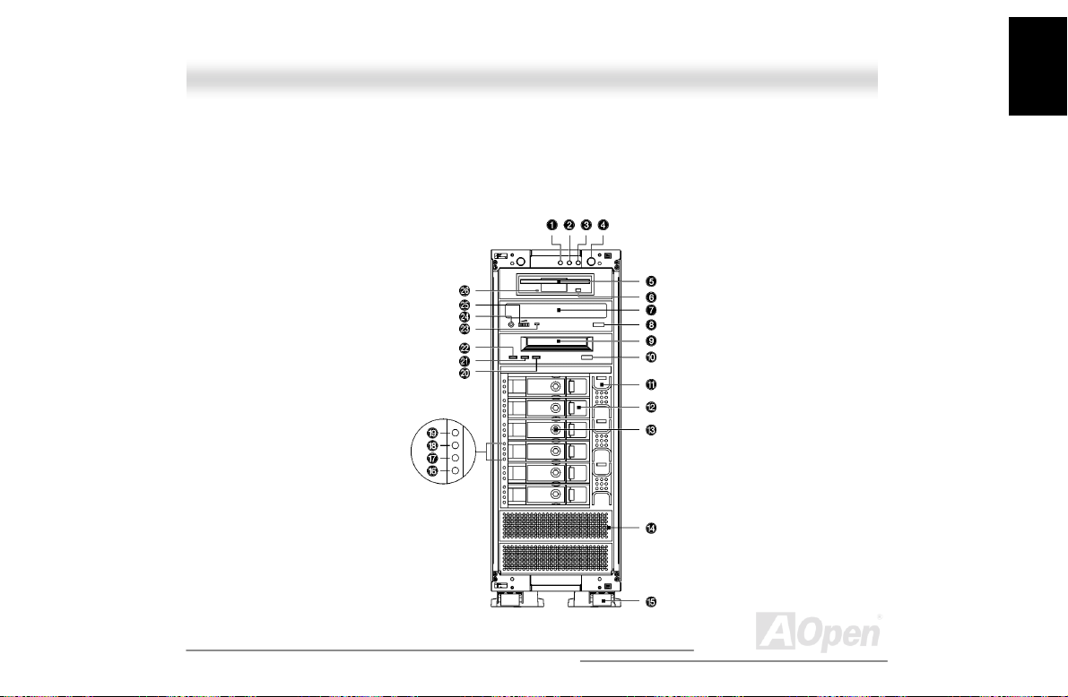
11..22 FFeeaattuurreess
1.2.1 Front Panel
Additional duplicate keys can be found at the back of t he system.
25
Open
Page 26
Instruction
A
Housing
No. Icon Item
1
2
3
4
5 3.5” FDD (Optional)
6 3.5” FDD eject button
7 CD-ROM tray (Optional)
8 CD-ROM tray eject button
9 Tape drive (Opt i onal )
10 Tape drive eject button
11 Hot-swap redundant BPL6 cage fan (Optional,
12 BPL6 HDD trays (Optional, s i x trays )
Event log LED
HDD access LED
Power/Suspend LED
Power button
three fans)
26
Open
Page 27
A
13 BPL6 HDD tray lock (Optional)
14 Drive bay cover
15 Housing wheels
Instruction
Housing
16
17
18
19
20 Drive LED (Amber)
21 Media LED (Green)
22 Clean LED (Green)
23 CD-ROM drive activity LED
24 Headphone/earphone port
25 Volume control
SCSI drive error LED
SCSI drive activity LE D
SCSI drive power LED
Hot-swap redundant fan fail LED
27
Open
Page 28

Instruction
A
Housing
26 3.5” FDD activity LED
28
Open
Page 29
A
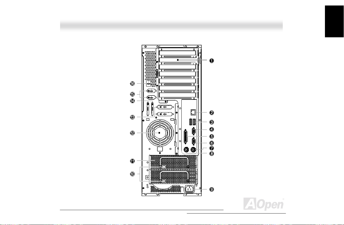
1.2.2 Real Panel
Instruction
Housing
29
Open
Page 30
Instruction
A
Housing
No. Item
1 Add-on card brackets
2 RJ45 LAN port
3 1st USB port
4 VGA D-sub 15-pins connector
5 Parallel port
6 Serial port (COM1)
7 PS/2 keyboard connector
8 PS/2 mouse connec t or
9 System power socket
10 Hot-swap power supply activity LED (Orange
when fail)
11 Hot-swap power supply (Redundant power
supply is optional)
12 Fan
30
Open
Page 31

A
13 Parallel port punch out hole
14 SCSI connector punch out hol e
15 Serial port punch out hole
16 NMI switch punch out hole
Instruction
Housing
31
Open
Page 32
Instruction
A
Housing
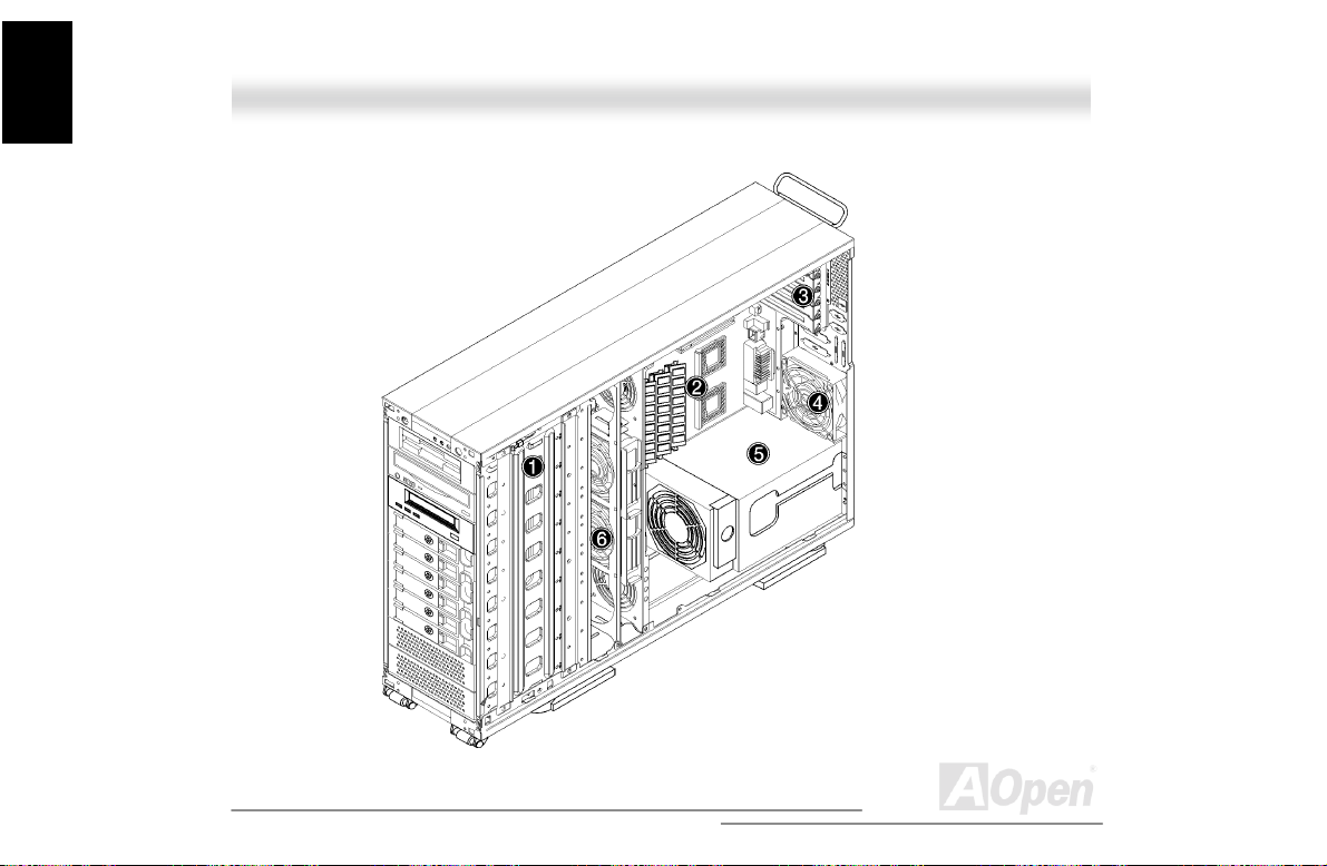
1.2.3 Internal Component
32
Open
Page 33
A
No. Item
1 Drive bays
2 DX3R Plus-U / DX3R-U M/B
3 Expansion brackets
4 Rear fan
5 Power supply
6 Front fans (Two fans)
Instruction
Housing
33
Open
Page 34
Instruction
A
Housing
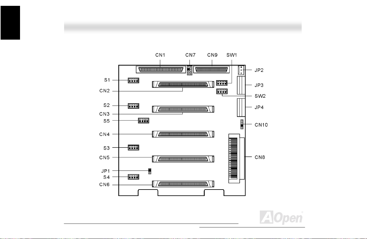
1.2.4 BPL6 Jumpers and Connectors (Optional)
34
Open
Page 35
A
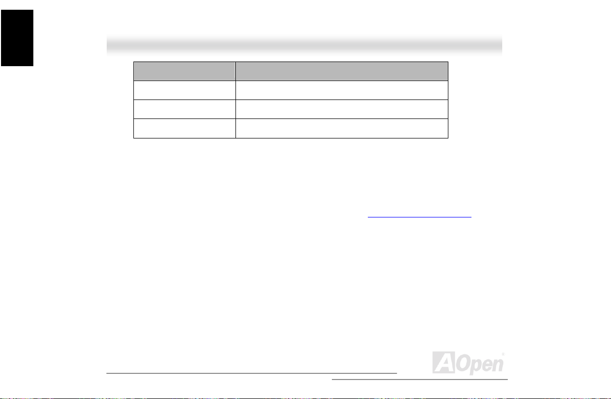
Connector or Jumper Description
CN1 I2C buffer connector
CN2 Front power LED connector
CN3 SCSI 68-pin P connector - Out
CN4 SCSI 68-pin P connector - Out
CN5 For SAF-TE card use
CN6 For SAF-TE card use
CN7 SCSI 68-pin P connector - In
CN8 SCSI 68-pin P connector - In
Fan 1 to 3 Hot-plug fan-sink connect or
JP1/JP4 Terminator power source
1. Short: Both from bac kplane and host
2. Open: Only from host
JP2 Power connector*
1
Instruction
Housing
35
Open
Page 36
Instruction
A
Housing
JP3 Power connector
Slot 1 to 6 SCSI hard disk slots
SW1 Slot 1 ID switch
SW2 Slot 2 ID switch
SW3 Slot 3 ID switch
SW4 Slot 4 ID switch
SW5 Slot 5 ID switch
SW6 Slot 6 ID switch
1. For the SCSI backplane board’s loading requirement, please insert t he i ndependent power
cable that don’t connect to other device to each power connector on back pl ane board.
2. When you use the LVD SCSI hot-swap cage to arrange your syst em hard drives, please
remove all the jumpers on each SCSI hard drive and use the switches on the backplane board
(SW1~SW6) to set the hard drive’s ID.
*2
36
Open
Page 37
Instruction
A
Housing
11..33 OOppeenniinngg tthhee HHoouussiinngg PPaanneellss
1.3.1 Opening the front panel door
To open front door:
1. Insert the key, push, and then turn it clock wise. If you are using the chassis for the first time,
you can find the key attach to t he rear of the chassis.
2. Press the latch and open the door
37
Open
Page 38

Instruction
A
Housing
1.3.2 Removing the front pane l door
The door is attached to the main housing by screw-less hinges. Follow these steps to remove the
door:
1. Unlock the door.
2. Open it up to a 45° angle.
3. Lift it up and pull out to detach.
38
Open
Page 39
A
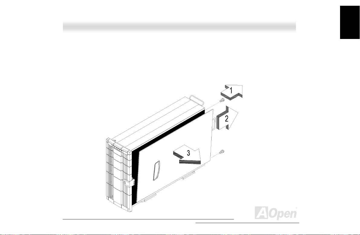
1.3.3 Removing the side panels
To remove the side panels:
1. Turn off the power to the system unit and unplug all c abl es.
2. Unscrew two thumbscrews located at t he back of the side panels.
3. Gently pull back the side panel and detach
Instruction
Housing
39
Open
Page 40

Instruction
A
Housing
11..44 IInnssttaalllliinngg aanndd RReemmoovviinngg DDeevviiccee DDrriivveess
The chassis has nine 5.25” drive bay. You can install additional storage devices like CD-ROM
drives, digital audiotape (DAT) drives or hard disk drives on the empty bays.
Turn off the power switch and unplug the power cord
before installing or removing dis kette drives.
1.4.1 Removing drive bay covers
The drive bay cover protects the inside of the chassis when the drive bay is not oc cupied.
To remove a drive bay cover:
1. Open the front panel door and remove the side panels. See “Opening the housing panel
page 38 for more information.
2. Detach the drive bay cover. Use a Phillips screwdriver to remove one screws located on the
right side of the drive bay cover.
3. Press the latch located on the left side of the drive bay using your finger. Pull out the drive bay
cover. Keep the drive bay cover for future use.
40
” on
Open
Page 41
A
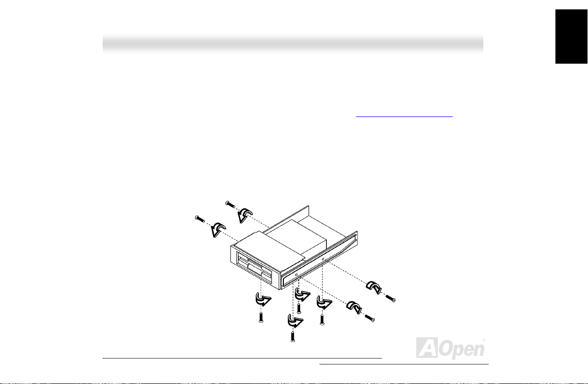
1.4.2 Installing and Removing a 3.5” Device Drive
The housing comes with a 5.25” plastic casing for installing 3.5” storage devices.
To install 3.5-inch device drives:
1. Open t he front panel of the housing. See “Opening the housing panel
page 38 for more information.
2. Attaching the 3.5” storage devices to the 5.25” plastic casing with four
screws.
3. Attaching the drive rail to one side of the plastic casing and secure it with
two screws. Do the same thing t o the other side.
” on
Instruction
Housing
41
Open
Page 42

Instruction
A
Housing
4. Insert the casing into the bay. If the drive bay has a cover, remove the
cover first. See “Removing drive bay covers
5. Secure the casing with two screws.
” on page 41.
42
Open
Page 43

Instruction
A
6. Connect the power cable and signal cables t o the storage devices.
7. Reinstall the side panel.
Housing
43
Open
Page 44

Instruction
A
Housing
To remove a 3.5” storage device:
1. Open the front panel door and remove the side panels. See “Opening the housing panels
page 38 for more information.
2. Disconnect the power and signal cabl es.
3. Us e a Phillips screwdriver to remove the screws locat ed on the right side of the plastic casing.
Gently pull out the plastic casing.
4. A gain, use a Phillips screwdriver to rem ove the sc rews located underneath t he storage device.
Detach the 3.5” storage device from the plastic casi ng.
5. Use the dri ve bay cover to cover the drive bay. Insert it into the empty drive bay and secure it
with one screw.
6. Reinstall the side panel.
” on
44
Open
Page 45

A
1.4.3 Installing and Removing a 5.25” Device Drive
You may install a CD-ROM, digital-audio tape (DAT), hard disk, diskette drive or any other
5.25-inch device into the drive bay.
To install 5.25-inch devices:
1. Open the front panel door and remove the side panels. See “Opening the housing panels
page 38 for more information.
2. Attach the driver rail to one side of the plastic casing and secure it with two screws. Do the
same thing to the other side.
3. Insert t he 5.25” storage drive into the bay. If the drive bay has a cover, remove the cover fi rst.
See “Removing drive bay covers
” on page 41.
” on
Instruction
Housing
45
Open
Page 46

Instruction
A
Housing
4. Secure the storage drive with two screws.
5. Connect the power cable and signal cables to the external devices.
6. Reinstall the side panels.
46
Open
Page 47

A
To remove a 5.25” storage device:
1. Open the front panel door and remove the side panels. See “Opening the housing panels
page 38 for more information.
2. Disconnect the power and signal cabl es.
3. Use a Phillips screwdriver to remove the screws located on the right side of the storage
device.
4. Gently pull out the storage drive to remove.
5. Use the dri ve bay cover to cover the drive bay. Insert it into the empty drive bay and secure it
with one screw.
6. Reinstall the side panel.
” on
Instruction
Housing
47
Open
Page 48

Instruction
A
Housing
11..55 IInnssttaalllliinngg aa HHoott--SSwwaapp CCaaggee ((OOppttiioonnaall))
The hot-swap cage occupied four drive bays. For more information about the backplane board,
please refer to “BPL6 Jum pers and Connectors
The BPL6 hot-swap cage includes the f ol l owing components:
” on page 35,
• One hot-s wap cage (with bac k plane board attached)
• Six hard disk drive trays
• Three hot-plug fan-sink modules
• One SCSI terminator
• Two SCSI cables
• One I
2
C cable.
48
Open
Page 49
A
1.5.1 Installing a HSC5 Hot-Swap Cage
To install the hot-swap cage into the housing:
1. Open the front panel door and remove the side panels. See “Opening the housing panels
page 38 for more information.
2. Attach two pairs of drive rails on each side of the hot-swap cage. Secure the rails with eight
screws.
3. Insert the hot-swap cage into t he dri ve bays and secure the hot-swap cage with four screws.
” on
Instruction
Housing
49
Open
Page 50
A
Instruction
Housing
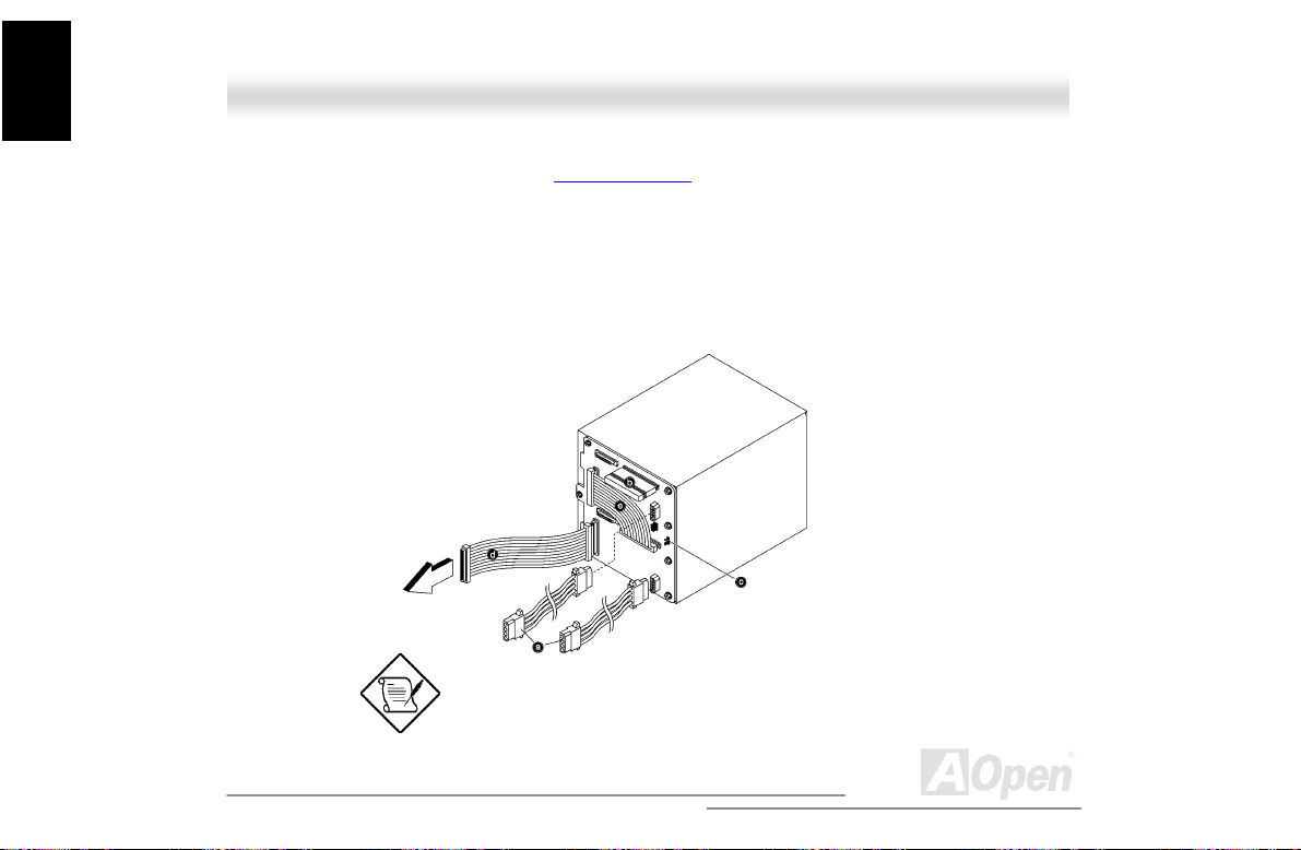
4. Attach the following to the BPL6 backplane board and attach the other end of the connector
cable to the motherboard (See “Motherboard Map
a. Power cables
b. SCSI terminator
2
C cable (CN1, connect to mot herboard)
c. I
d. SCSI cable (Connect to motherboard)
e. SCSI channel A to c hannel B connection cable
We suggest you use the lower four 5.25” bays for better heat
dissipation.
50
” on page 73).
Open
Page 51

A
1.5.2 Hot-Swapping SCSI SCA Hard Disk Drive
The hot-swap cage supports up to six hot-swapping SCSI SCA hard disk drives. You can hot-swap
(remove an replace) a hard disk drive any time when it fails to operate (indic ated by the yellow
LED).
Do not remove a hard disk drive when active. This may
cause undue damage to the hard disk drive.
Instruction
Housing
51
Open
Page 52
Instruction
A
Housing
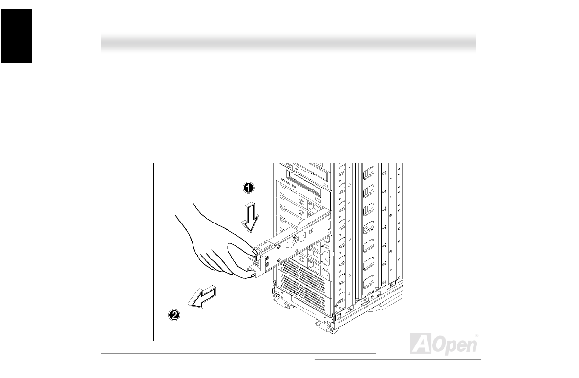
Follow these steps to install a hot swappable SCSI dri ve:
1. Use the hex key provided with the system to unlock the drive tray.
2. Use your finger to release the drive tray and t hen pul l i t out.
52
Open
Page 53

A
3. Place a hard disk on the tray. Secure it with four screws with the metal holder as shown below.
4. Insert the tray into the hot-swap cage with the lever still extended. Make sure that the drive is
properly inserted before closing t he l ever.
5. Push the lever back until it clicks into place.
Instruction
Housing
53
Open
Page 54
Instruction
A
Housing
1.5.3 Hot-Swapping the Hot-Plug Fan-Sink Module
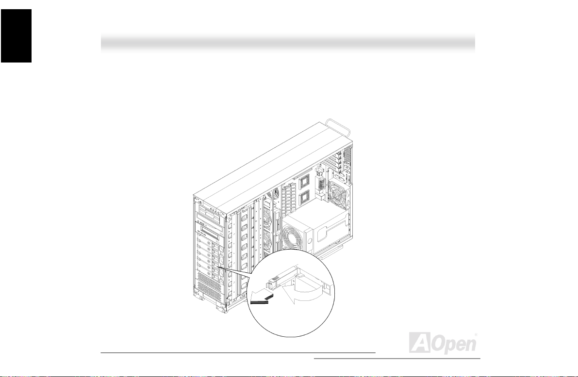
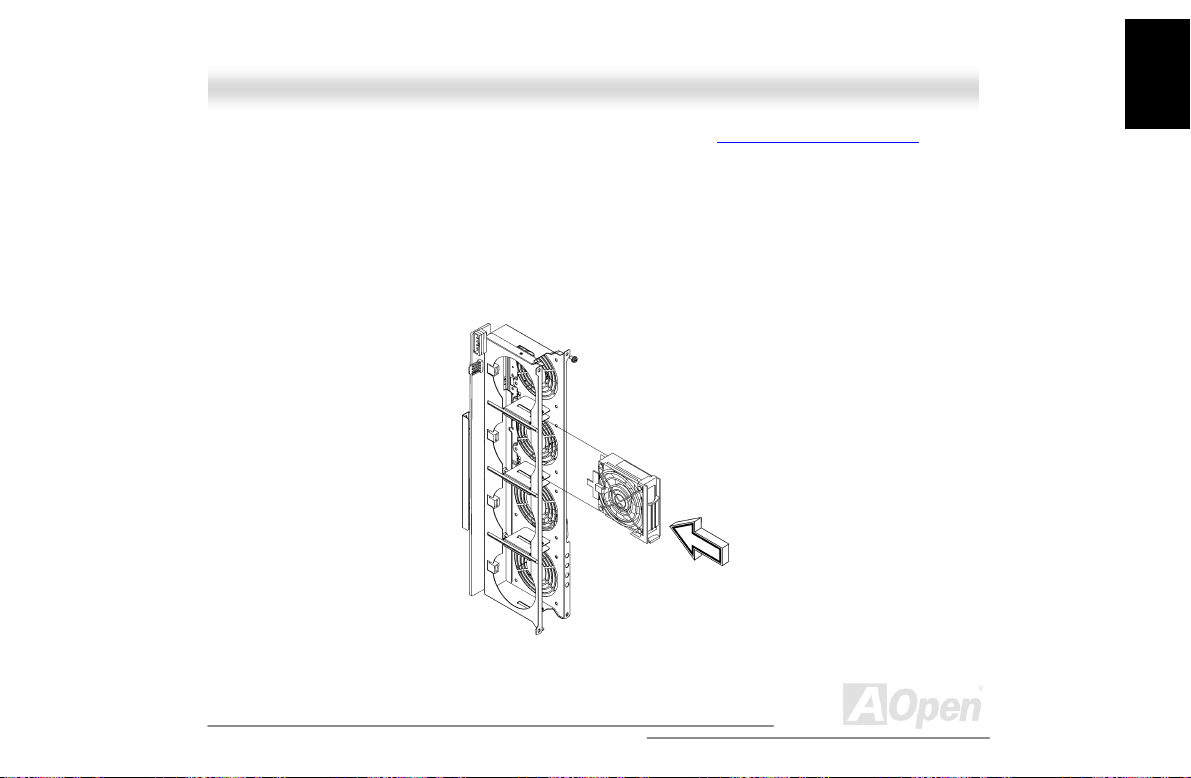
The hot-swap cage supports up to three hot-plug fan-sink modules to keep it cool. You can
hot-swap (remove and replace) a hot-plug fan-sink any time when it fails to operate (indicated by
the yellow LED).
Follow these steps to replace a hot-plug fan-sink module:
1. Insert your pointing finger and your thumb into the fan-sink module.
2. Squeeze the latch to release the fan and gently pull it out.
54
Open
Page 55
A
3. Insert a new fan-sink into the hot -swap cage. Push the fan-sink unt i l i t l o cks into place.
Instruction
Housing
55
Open
Page 56

Instruction
A
Housing
11..66 HHoott--SSwwaappppiinngg RReedduunnddaanntt PPoowweerr SSuuppppllyy
The power subsystem consists of two hot-swappable power supply module bays that allow the
installation of two 337-watts power supply modules in a hot-swappa ble redundant configuration. A
redundant power configuration enables a ful ly-configure system to continue running even if one
power supply fails.
The SV520 comes with one hot-swappable redundant power
supply installed.
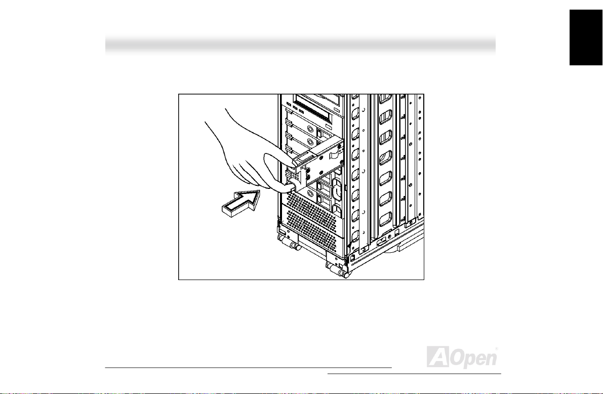
To install a hot-swappable redundant power supply:
1. Insert the power supply into the power supply c age
Make sure that the power supply is properly ins erted.
56
Open
Page 57
A
2. Secure the power supply with a screw.
Instruction
Housing
57
Open
Page 58

Instruction
A
Housing
To remove a hot-swappable redundant power supply:
An orange colored LED indicates a failed power supply.
1. Remove the screw using a Phillips screwdriver.
2. Press the latch to rel ease the power supply and gently pull it out using t he metal handle.
58
Open
Page 59

Instruction
A
The power supply subsystem shoul d supply a minimum of
337 Watts to the whole system. If you only have one power
supply or if you have tow power supplies and are planning to
remove both of them, remember to turn off the power first
and disconnect the power cord from t he el ectrical outlet.
Housing
59
Open
Page 60

Instruction
A
Housing
11..77 RReeppllaacciinngg tthhee PPoowweerr SSuuppppllyy FFaann
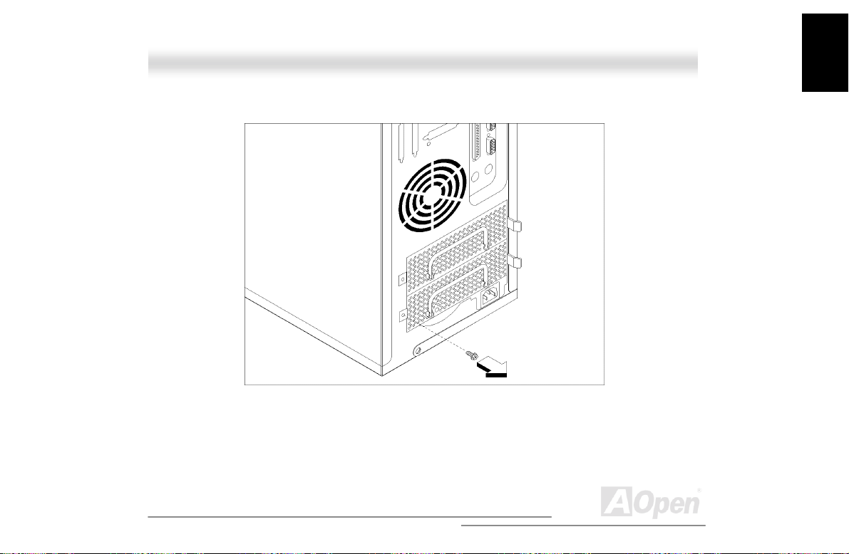
To replace the power supply fan:
1. Open the front panel door and remove the ri ght panel. See “Opening the housing panels
page 38 for more information.
2. Insert your pointing finger and thumb into the power supply fan.
3. Squeeze the latch to release the fan and gently pull it out.
60
” on
Open
Page 61

A
4. Insert a new fan and gently push it down until it l ocks into place.
Instruction
Housing
61
Open
Page 62

Instruction
A
Housing
11..88 HHoott SSwwaapp RReedduunnddaanntt CChhaassssiiss FFaann
The chassis can house five cooling fans, however, it only needs a minimum of three cooling fans to
operate properly. These fans are distributed inside the chassis to cool down the system (two in
front and one at the back). The rear-cooling fan is fixed and not hot swappable. You have to
shutdown the system before changing the rear-cooling fan. However, the cooling fans in front are
hot swappable. When the front cooling fans becomes defective, you can simple take it out and put
a new one in even when the system is operating.
Make sure that there are three cooling fans (two in front and
one at rear) distributed in the chassis to ensure proper
system operation. Also, remember to shutdown the system
when changing a defective rear-cooling fan.
62
Open
Page 63

A
1.8.1 Hot-Swap Fan Base Board
Instruction
Housing
63
Open
Page 64
Instruction
A
Housing
Connector or Jumper Description
JP1 Power connector
JP2 Signal cable (4-pin)
Fan1 to 4 Hot-plug fan connector
1.8.2 Replacing Housing Fans
To c hange a rear housing fan:
1. Shutdown the system
2. Open the front panel door and remove the side panels. See “Opening the housing panels
page 38 for more information.
3. Remove the fan cable from the motherboard.
4. Press the fan holder arm out ward until i t is loose enough for the cooling f an to come through.
5. Replace the defective cooli ng fan.
6. Reattach the fan cable to the motherboard.
7. Close the chassis panel and restart the system.
To c hange a f ront hot-swap housing fan:
” on
64
Open
Page 65
A
1. Open the front panel door and remove the side panels. See “Opening the housing panels” on
page 38 for more information.
2. See which of the fan is defect i ve. Refer to the LED located at t he bottom side of each fan.
3. Inse rt your forefinger int o the grasp hole and use your thum b to press the latch to release the
defective fan.
4. Pull out the fan and replace it with a good one. Make sure that the fan is operati ng properl y.
5. Close the chassis panel.
Instruction
Housing
65
Open
Page 66
Instruction
A
Housing
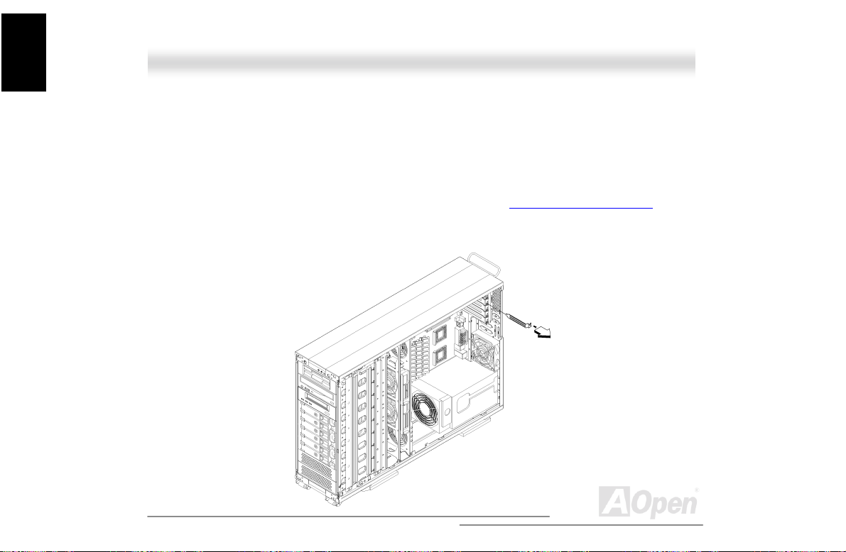
11..99 IInnssttaalllliinngg aann EExxppaannssiioonn CCaarrdd
The expansion card connects to the motherboard expansion slots. The number of expansion slots
available depends on the motherboard that you want to install. However, the chassis can only
accommodate a maximum of seven expansion cards.
To install an expansion card:
1. Open the front panel door and remove the side panels. See “Opening the housing panels
page 38 for more information.
2. Remove the expansion slot bracket opposite an empty expansion slot. Save the screw for
later use.
66
” on
Open
Page 67
A
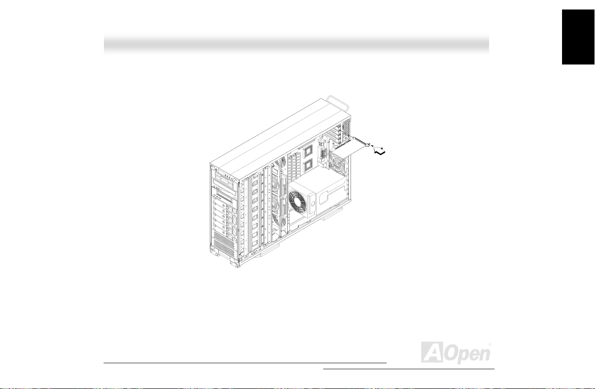
3. Align and insert the expansion card to the empty expansion slot.
4. Secure the expansion card to the chassi s with a screw.
5. Reinstall the side panel.
Instruction
Housing
67
Open
Page 68

Installation
A
Hardware
CChhaapptteerr 22 HHaarrddwwaarree
IInnssttaallllaattiioonn
22..11 OOvveerrvviieeww
Plus-U/DX3R-U also integrates the Intel
WOL
(Wake On LAN) function for better remote site management. For expandability, the DX3R
Plus-U/DX3R-U includes four 64bit/33MHz PCI slots, two 32bit/33MHz PCI s lots and four DIMM
slots that allows memory installation to a maximum of 4GB using four 1G (1024MB) SDRAM
(Synchronous DRAM). For Connectivity, the DX3R Plus-U/DX3R-U supports two USB connector, a
video port and other standard features such as two serial ports, one enhanced parallel port with
The AOpen DX3R Plus-U/DX3R-U is a PCI bus based dual
processor motherboard built on an extended ATX baseboard.
It comes with two socket 370 processor slots utilizing two
®
Intel
Pentium® III processors integrated with the Server
Works LE north and OSB4 south bridge chipsets. The dual
channel SCSI architecture supports Ultra160 SCSI
bandwidth of up to 160MB/s for each channel. The DX3R
®
82550 10/100Mbps PCI Ethernet chipset that supports
68
with
Open
Page 69

A
EPP/ECP feature, a dis kette drive interface and two embedded hard disk interfaces.
Installation
Hardware
69
Open
Page 70

A
Installation
Hardware
22..22 FFeeaattuurree HHiigghhlliigghhtt
CPU
Supports single/dual Intel® FC-PGA Pentium® III 533MHz~1.4GHz with 100/133MHz FSB (Front
Side Bus) designed for Socket 370 technology. FSB133 MHz Coppermine and Tualatin CPU are
also supported up to 1.2GHz
Chipset
The Server Works CNB30LE chipset incorporated as a north bridge is in charge of the host bus
interface and memory bus control. The memory bus control supports two and four way interleaved
of PC-100 and PC-133 SDRAM registered ECC
32bit PCI bus running at 33MHz and another sec ondary PCI bus running at 33/66MHz.
DIMM up to 4GB. The north bridge provides one
Memory
The four DIMM sockets on board allow memory upgrade to a maximum of 4GB using four 1024MB
registered SDRAM (Synchronous DRAM) DIMMs. For data integrity, the default setting of the ECC
(Error-Correcting Code) function of the memory system in BIOS is enabled. The DX3R
Plus-U/DX3R-U supports both 100 and 133MHz registered SDRAM only, 66MHz SDRAM is not
supported.
70
Open
Page 71

A
Expansion Slots
Including four 64-bit/33MHz, two 32-bit/33MHz PCI and one AGP Pro slots. The PCI local bus
throughput can be up to 264MB/s. The Intel
display sophistication and speed. The AGP Pro video cards support data transfer rates up to
1066MB/s. As DX3R Plus-U/DX3R-U include one AGP Pro expansion slot for a bus mastering AGP
graphics card. For AD and SBA signaling, DX3R Plus-U/DX3R-U can supports 133MHz 2X/4X
mode.
®
AGP Pro specification provides a new level of video
SCSI On-board (DX3R Plus-U only)
The dual channel Adaptec AIC-7899 chip host adapter delivers Ultra160/m SCSI data transfer rates
which doubles the Ultra3 SCSI data transfer rate of up to 160MB/s. W ith two channels, it del ivers a
total of 320MB/s bandwidth. In addition, the AIC-7899 features a 66MHz, 64bit P CI interface that
supports zero wait-state memory that also operates on 33MHz, 32bit PCI buses. It supports up to
15 devices on a 12 meters cable (or 25 meters in a point to point configurat ion), making it i deal for
both clustering and RAID c onf i gurations.
Video Subsystem
The ATI Rage XL harbors 2D and 3D display capacities that bring life to any multimedia and work
applications. With a remarkable color depths and high resolutions of up to 1280*1024 for an
Installation
Hardware
71
Open
Page 72

A
Installation
Hardware
enhanced visual experience on your system. The on-board ATI Rage XL chipset comes with 4MB
of video memory and supports up to 1280*1024 display mode at high colors with a maximum of
4MB video memory option.
Intel 82550 LAN controller
Another cost-effecti ve f eature for network solution is the integration of Intel 82550 10/100 Mbps
Fast Ethernet controller that supports:
1. Advanced Configuration and Power Interfac e (ACPI
2. Wake on Magic Packet.
3. Wake on interesting packet .
4. Advanced System Management B us (SMB) based manageability.
5. Wired for Management (WfM) 2.0 compl i ance.
6. IP checksum assist.
7. PCI 2.2 compliance.
8. PC99 compliance.
) 1.20A based power management.
72
Open
Page 73

A
Power Management/Plug and Play
The DX3R Plus-U/DX3R-U supports the power management function that confirms to the
power-saving standards of the U.S. Environmental Protection Agency (EPA) Energy Star program.
It also offers Plug-and-Play that helps save users from configuration problems, thus making to
system user-friendl i er.
Super Multi-I/O
The DX3R Plus-U/DX3R-U provides two high-speed UART compatible serial ports and one parallel
port with EPP and ECP capabilities. UART2 can also be directed from COM2 to the Infrared
Module for the wireless connections .
Installation
Hardware
73
Open
Page 74

A
A
A
r
p
r
r
r
r
r
r
r
r
r
r
Installation
Hardware
22..33 MMootthheerrbbooaarrdd MMaapp
JP10 CPU Terminator Jumpe
BP (Backplane) Connecto
WOL (Wake On LAN) Connect
32bit PCI Slot x2
64bit PCI Slot x4
External S
JP5 System Event Clear Jumpe
Adaptec AIC-7899 Ultra160
JP8 Password Check Jumpe
System Event LED Connecto
JP6 SCSI terminator Jumpe
eaker Connecto
4Mb Flash ROM BIOS
FDD Connecto
SCSI Controlle
68-pin SCSI connector x2
2nd USB Connecto
50-pin SCSI Connecto
CPU 2
IDE Connector
NMI Switch Connector
System Fan Connector (4-pins)
CPU 1 CPU 2
RJ45 LAN Jack
PC99 Colored Back Panel
COM2 Port Connector
®
82550 10/100Mbps
Intel
Ethernet Controller
TI Rage XL Video Chip with 4MB
Video RAM onboard
TX Power Connector
Low ESR Capacitor (1500uF)
370-pin CPU Socket x2 (Pentium III, Tualatin and
Coppermine CPU supported)
CPU Fan Connector with H/W Monitoring x2
Thermal Sensor Connector x2
®
Server Works
PC 100/133 DIMM x4 (Maximum up
to 4GB, 1GB per DIMM slot)
Redundant SPS Connector
Front Panel Connector
ServerSet™ III LE Chipset
Open
74
Page 75

A
22..44 BBlloocckk DDiiaaggrraamm
Secondary PCI Bus
(64b/33/66MHz)
Adaptec
AIC-7899
Ultra160
SCSI
ASM
Socket
Coppermine,Tualatin
USB E-IDE
UDMA/33
Front Side Bus @ 100MHz/133MHz
CNB30LE
Host Bridge
I2C Bus
100/133MHz
Up to 1.0 GB/s
Memory Bandwidth
OSB4
PCI-ISA Bridge
BIOS
75
Socket
Coppermine,Tualatin
Up to 4GB SDRAM
Primary PCI Bus (32b/33MHz)
Intel
82550
ISA Bus
Super I/O
(SMC)
VGA
Open
Installation
Hardware
Page 76

A
Installation
Hardware
22..55 CCoonnnneeccttoorrss aanndd JJuummppeerrss
The table below lists the different connectors or jumpers on the motherboard and their respective
functions.
Connector or
Jumper
CN3 ATX Power Connector 76
CN4 Keyboard/Mouse Connector 93
CN5 Serial Port Connector 93
CN7/CN25 CPU1/CPU2 Thermal Sense Connector 72
CN8/CN24 CPU1/CPU2 Fan Connector 71
CN9 Redundant SPS Connector 77
CN10 Printer/VGA/RS232 Connector 93
CN13/19/20/23/28 System Fan Connector (4-pins) 71
CN14 USB 1/2 Connector 93
CN15 Front Panel Connector 83
CN16 RJ45 LAN Connector 93
CN18 NMI Switch Connector 87
CN21 IDE Connector 78
Description Page
76
Open
Page 77

A
Connector or
Jumper
CN29 50-pins Narrow SCSI Connector 81
CN30 2nd USB Connector 86
CN35/CN38 68-pins SCSI Connector 81
CN37 WOL Connector 84
CN40 FDD Connector 78
CN41 System Event LED Connec tor 92
CN42 BP (Backplane) Connector 88
CN46 External Speaker Connector 89
JP5 System Event Clear Jumper 92
JP6 SCSI Terminator Jumper 82
JP8 Password Check Jumper 91
JP10 CPU Terminator Jumper 73
Description Page
77
Open
Installation
Hardware
Page 78

A
k
e
u
m
Installation
Hardware
22..66 HHaarrddwwaarree
This chapter describes j umpers, connectors and hardware devices of this motherboard.
Note: Electrostatic discharge (E SD) can damage your processor, dis
drives, expansion boards, and other components. Always observe th
following precautions before you install a system component.
1.Do not remove a component from its protective packaging until yo
are ready to install it.
2.Wear a wrist ground strap and attach it to a metal part of the syste
unit before handling a component. If a wrist strap is not available,
maintain contact with the system unit throughout any procedure
requiring ESD protection.
78
Open
Page 79

A
2.6.1 CPU Installation
CPU Pin 1 and cut edge
CPU socket level
1. Pull up the CPU socket level and up to 90-degree
angle.
2. Locate Pin 1 in the socket and l ook for a (golden)
cut edge on the CPU upper interface. Match Pin 1
and cut edge. Then insert the CPU into the socket.
3. Press down the CPU socket level and finish CPU
installation.
Note: If you do not match t he CP U socket
Pin 1 and CPU cut edge well, i t may
damage the CPU.
Installation
Hardware
79
Open
Page 80

A
Installation
Hardware
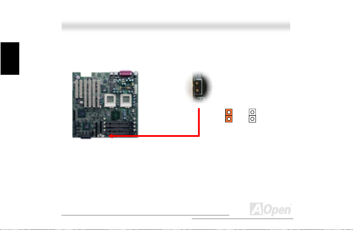
2.6.2 CPU Fan (3-pins) & Housing Fan (4-pins) Connector
Plug in the CPU fan cable to t he 3-pi n CPU FAN connector and housing fan cable to the Housing
Fan connector.
System fan connector
CPU fan connector
+12V
Fan Off
Fan Fail
Sense
Note: Some CPU fans do not have
sense pin, so that cannot support fan
monitoring.
GND
+12V
Sense
80
Open
Page 81

A
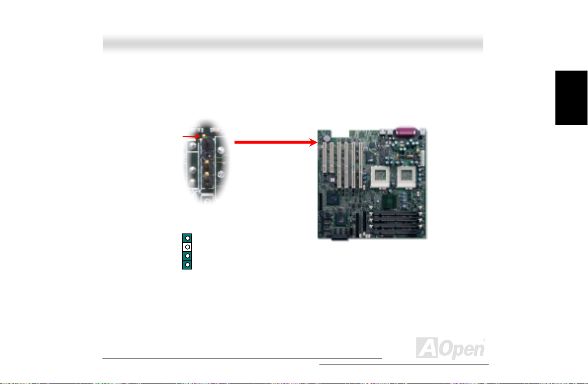
2.6.3 Thermal Sensse Connector
The Thermal Sense Connector (CN7 & CN25) provides you to use the thermal sensor to detect the
temperature of the components on the motherboard.
Sense
GND
Thermal Sense connector
Installation
Hardware
81
Open
Page 82
A
(
)
Installation
Hardware
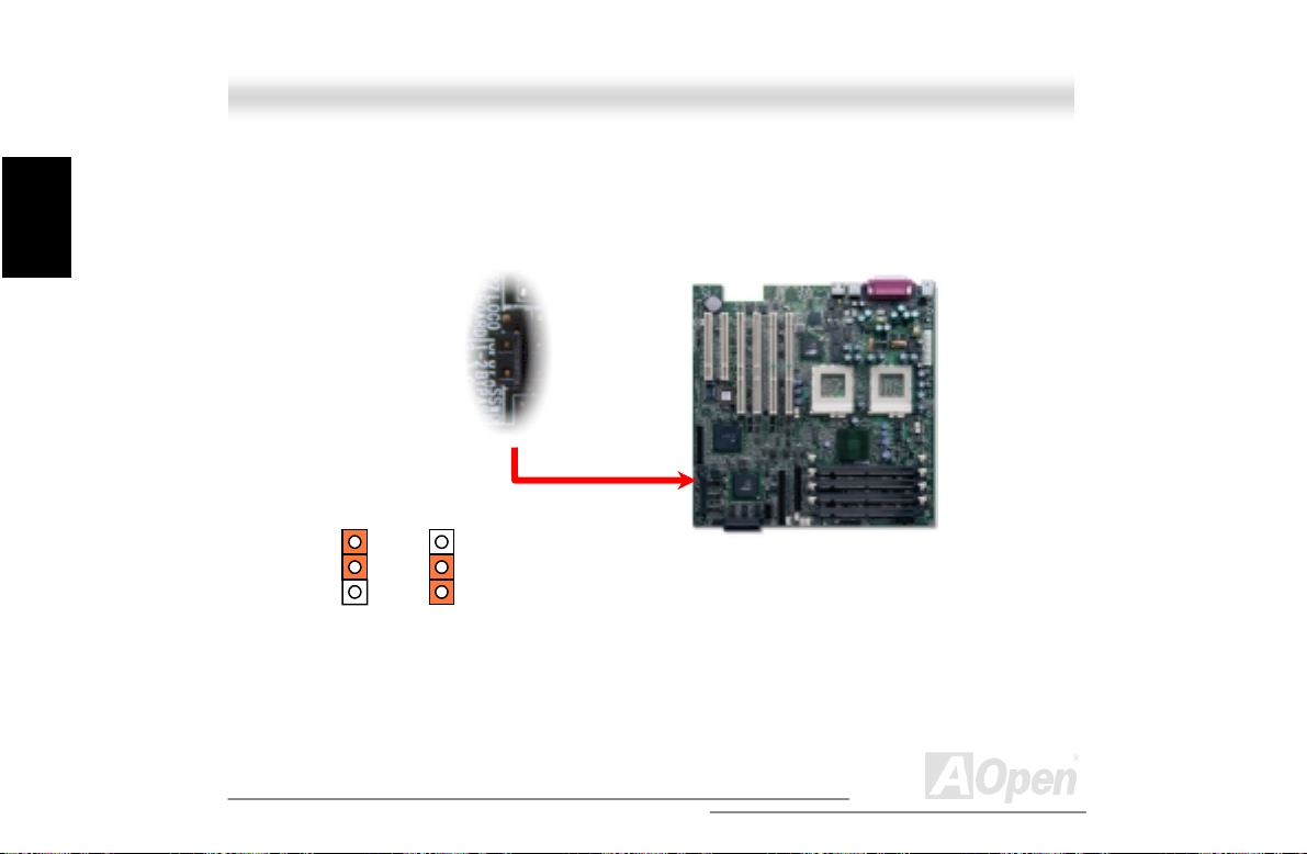
2.6.4 JP10 CPU Terminator Jumper
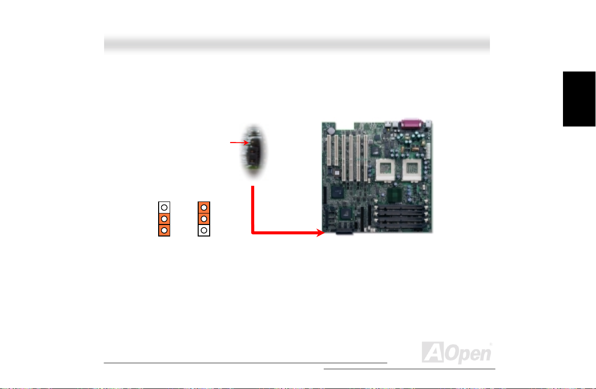
When you are using single Intel® Pentium III/Celeron CPU with DX3R Plus-U/DX3R-U, you must
short the pin-1 and pin-2 to enable CPU terminator function.
Disable
(Default)
Enable
Default
82
Open
Page 83
A
2.6.5 DIMM Slots
This motherboard has four 168-pin DIMM sockets that allow you to install PC100 or PC133
Registered memory up to 4.0GB.
DIMM can be single side or double side; i t has 64 bit data and 2 or 4 clock signals. We strongly
Note: The ServerSet™ III LE chipset
only allows you using the Registered
SRAM with it.
83
DIMM 1
DIMM 2
DIMM 3
Open
Installation
Hardware
Page 84
A
t
M
Installation
Hardware
recommend choosing 4-cl oc k SDRAM for its reliability
Tip: To identify 2-clock and 4-clock DIM M , you may
check if there are traces connected to the golden
finger pins 79 and 163 of the SDRAM. If there are
traces, the SDRAM is probably 4-clock; otherwise, i
is 2-clock.
Tip: To identify single-side or double-side DIMM,
check golden finger pin 114 and pin 129. If there are
traces connected to pin 114 and pin 129, the DIM
is probably double side; otherwise, it is single-side.
84
Open
Page 85
A
V
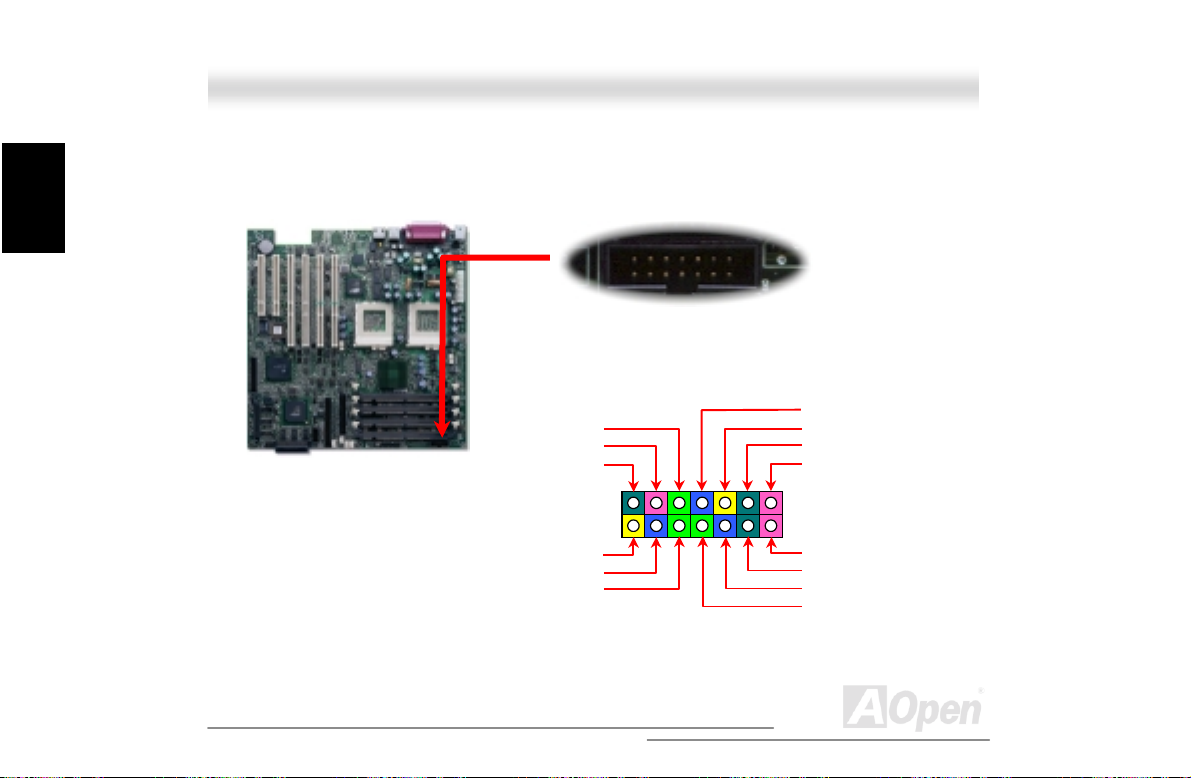
2.6.6 ATX Power Connector
The DX3R Plus-U/DX3R-U uses 20-pins ATX power connector. Make sure you plug the connector
in the right direction.
+3.3
-12V
COM
PS-ON
COM
COM
COM
-5V
+5V
+5V
+3.3V
+3.3V
COM
+5V
COM
+5V
COM
PWR OK
5VSB
+12V
Installation
Hardware
85
Open
Page 86
A
A
Installation
Hardware
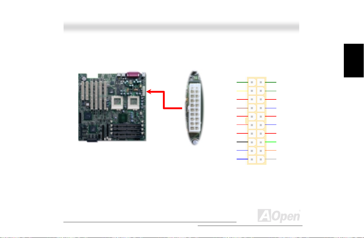
2.6.7 Redundant SPS Connector
The Redundant SPS connector provides the signal to hardware monitoring modul e i f i t had fail.
1
214
Present 1
2
C CLK
I
Fan 1 Fail
PS 1 Fail
PS 2 Fail
Fan 2 Fail
Present 2
5VSB
PS_ON
PS 3 Fail
Fan 3 Fail
2
I
CD
Present 3
GND
13
86
Open
Page 87
A
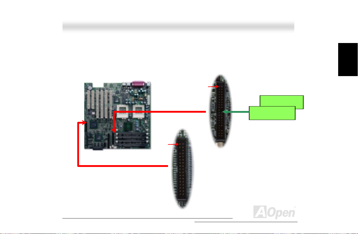
2.6.8 IDE and Floppy Connector
Connect 34-pin floppy cable and 40-pin IDE cable to floppy connector FDC and IDE connector.
Pin1 of cable is normally marked with red color. Be careful of the pin1 orientation. Wrong
orientation may cause system damage.
Pin 1
Pin 1
IDE Slave (2nd)
IDE Master (1st)
IDE
Connector
FDD
Connector
Installation
Hardware
87
Open
Page 88
A
d
d
r
Installation
Hardware
As known, each IDE channel supports two IDE devices. In order to work together, the two devices
on each channel must be set differently to Master and Slave mode. Either one can be the hard
disk or the CDROM. The setting as master or slave mode depends on the jumper on your IDE
device, so please refer to your hard di sk and CDROM manual accordingly.
Warning: The specification of the IDE cable i s a
maximum of 46cm (18 inches), make sure your c abl e
does not exceed this lengt h.
Tip: For better signal quality, it is recommende
to set the far end side device to master mode an
follow the suggested sequence to install you
new device. Please ref er to above diagram.
88
Open
Page 89
A
This motherboard supports Ultra DMA /33 mode. Following table lists the trans f er rate of IDE PIO
and DMA modes. The IDE bus is 16-bit, which means every transfer is two bytes.
Mode
PIO mode 0 30ns 20 600ns (1/600ns) x 2byte = 3.3MB/s
PIO mode 1 30ns 13 383ns (1/383ns) x 2byte = 5.2MB/s
PIO mode 2 30ns 8 240ns (1/240ns) x 2byte = 8.3MB/s
PIO mode 3 30ns 6 180ns (1/180ns) x 2byte = 11. 1MB/s
PIO mode 4 30ns 4 120ns (1/120ns) x 2byte = 16.6MB/s
DMA mode 0 30ns 16 480ns (1/480ns) x 2byte = 4.16MB/s
DMA mode 1 30ns 5 150ns (1/150ns) x 2byte = 13.3MB/s
DMA mode 2 30ns 4 120ns (1/120ns) x 2byte = 16.6MB/s
UDMA/33 30ns 4 120ns (1/120ns) x 2byte x2 = 33MB/s
Clock per
33MHz PCI
Clock
Count
Cycle Time Data Transfer Rate
Installation
Hardware
89
Open
Page 90

A
Installation
Hardware
2.6.9 68-pins Ultra160/50-pins Narrow SCSI Connector (DX3R Plus-U only)
The DX3R Plus-U provides two 68-pins Ultra Wide/Ultra2/3 and one 50-pins Narrow SCSI
connectors for 8/16-bit or 16-bi t differential SCSI devices .
50-pins
Narrow
SCSI
68-pins
Ultra160
SCSI
90
Open
Page 91
A
2.6.10 JP6 SCSI Channel Terminator Control (DX3R Plus-U only)
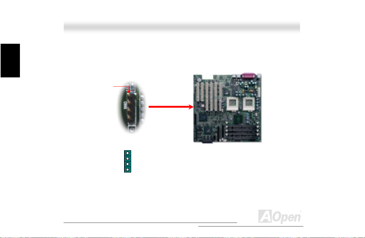
The JP6 allows you to enable or disable the on-board S CS I terminator control function.
On
(Default)
Pin 1
11
Off
Installation
Hardware
91
Open
Page 92

A
R
Installation
Hardware
2.6.11 Front Panel Connector
Attaching such as power LED, speak er, reset switch, power switc h connector, etc.… to
corresponding pins.
+5V
GND
PW
+5VS
GND
+5V
HDD LED
HDD LED
+5V
ATX
1
2
1
2
Power LED
Reset Switch HDD LED
Chassis
21
22
RST S/W
INT S/W
21
22
GND
GND
92
Open
Page 93

A
2.6.12 WOL (Wake on LAN) Connector
To use Wake On LAN function, you must have a Ethernet card with chipset that supports this
feature, and connect a cable from LAN card to motherboard WOL connector. The system
identification information (probably IP address) is stored on network card and because there is a lot
of traffic on the Ethernet, you need to install network management software, such as ADM, for the
checking of how to wake up the system. Note that, at least 600mA ATX standby current is required
to support the LAN card for th i s function.
+5VSB
GND
LID
93
Open
Installation
Hardware
Page 94

A
Installation
Hardware
The picture shown below is only for your reference.
WOL Connector
(Motherboard Side)
WOL Connector
(Ethernet Card Side)
94
Open
Page 95

A
2.6.13 Support 2nd USB Port
This motherboard supports four USB ports. Two of them are on back panel connector, the other two
are on the left-bottom area of this motherboard. With proper cable, you can connect them to front
panel.
USBPWR6
USBP2-
USBP2+ USBP3+
USBPWR8 USBP3-
GND USBPWR5
GND
USBPWR7
Installation
Hardware
95
Open
Page 96
A
Installation
Hardware
2.6.14 NMI (Non-Maskable Interrupt) Switch Jumper
Non- Maskable Interrupt used for event handling. When event is occurred, system will receive an
NMI and execute a unique task. To disable this function, please short CN18 by jumper cap.
Close
Open
(Default)
96
Open
Page 97
A
2.6.15 BP (Backplane) Connector
The BP connector provides the signals of BPL6 backplane to ASM (Advanced Server Management)
software monitoring program, such as storage category, HDD fault, fan present, fan fault.
Pin 1
GND
1
N/C
2
C CLK
I
I2CDA
97
Open
Installation
Hardware
Page 98
A
Installation
Hardware
2.6.16 External Speaker Connector
If you want to use external case-mounted speaker instead of internal buzzer, the 4-pins external
speaker connector can let you connect with external case-mounted speaker.
Pin 1
GND
N/C
N/C
+5V
98
Open
Page 99

A
2.6.17 JP5 System Event Clear Jumper
The JP5 allows you to clear the system event log record whenever the event log area is full.
Please short the JP5 by j umper cap if you want to clear all of the event logs.
Clear
Normal
(Default)
Installation
Hardware
99
Open
Page 100
A
Installation
Hardware
2.6.18 JP8 System BIOS Password Check
There is one jumper cap over pin2 and pin3 of JP8 for system BIOS password check. If you want to
use the system without BIOS password check, please remove the jumper c ap to short pin1 and
pin2.
1
Disabled
1
Enabled
(Default)
100
Open
 Loading...