

Page 1
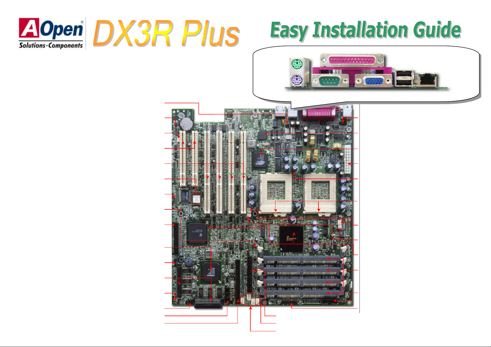
COM2 Port Connector
Low ESR Capacitor (1500uF)
ATX Power Connector
4MB Video RAM
onboard
Ethernet Controller
370-pin CPU Socket x2
CPU Fan Connector with H/W Monitoring x2
Server Works
®
Serv
erSet™ III LE Chipset
Thermal Sensor Connector x2
Redundant SPS Connector
Front Panel Connector
BP (Backplane) Connector
WOL (Wake On LAN) Connector
32bit PCI Slot x2
64bit PCI Slot x4
4Mb Flash ROM BIOS
Ext
ernal Speaker Connector
JP5 System Event Clear Jumper
FDD Connector
JP8 Password Check Jumper
IDE Connector
SCSI Controller
System Event LED Connector
68-pin SCSI connector x2
JP6 SCSI terminator Jumper
2nd USB Connector
NMI Switch Connector
JP10 CPU Terminator Jumper
50-pin SCSI Connector
System Fan Connector (4
-
pins)
PS/2 Mouse
Connector
SPP/ECP/EPP Print Port
USB
Connector
RJ45 LAN
Connector
Adaptec AIC-7899 Ultra160
CPU 2
PS/2 Keyboard
Connector
COM1 Port
CPU 1
VGA Connector
Intel® 82559 10/100Mbps
ATI Rage XL Video Chip with
PC 100/133 DIMM x4 (Maximum up
to 4GB, 1GB per DIMM slot)
Page 2
Everything you need to boot this
motherboard is included in this
Easy Installation Guide. For more
information, a complete
Online
can be found in the
. Thanks for
If you do not match the CPU
socket Pin 1 and CPU cut edge
+12V Fan Off
(GND)
Fan Fail
Sens
or
GND
Sensor
+12V
connector
User's Manual
Bonus Pack CD Disc
the help of saving our earth!
Ø Hard Drive IDE Cable x 1
Ø Ultra 160 SCSI 68 pin Cable x 1
Ø Ultra Narrow 50 pin Cable x 1
Ø 2nd USB cable x 1
Ø COM Port Cable x 1
Ø Bonus Pack CD x 1
Ø Norton Anti-Virus CD x 1
Ø ASM Lite CD x 1
Ø CPU Terminator x 1
Ø IO Bracket for SV520 x 1
Ø IO Bracket for Open Market Housing x 1
Ø SCSI Utility Diskette Pack x 1
Ø Screw Pack x 1
Ø User Manual x 1
Ø This Easy Installation Guide x 1
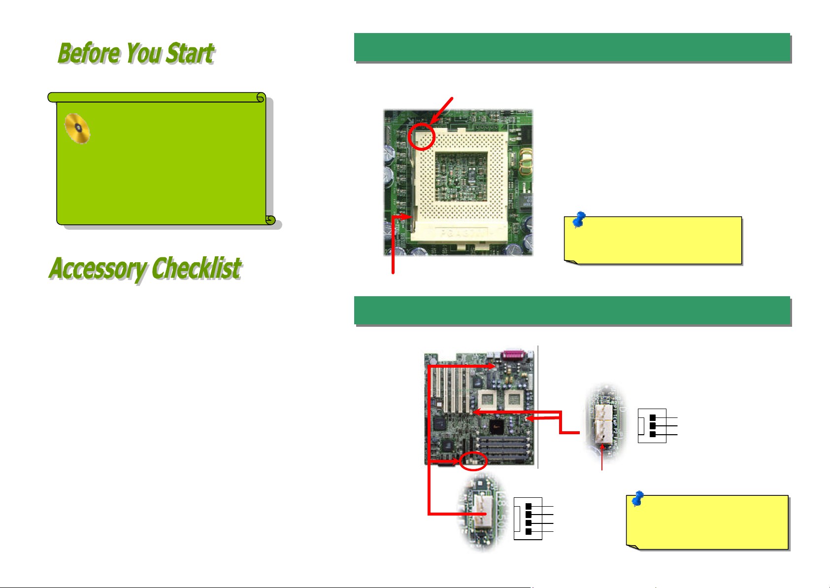
1. Installing CPU
1. Pull up the CPU socket level and up to
CPU Pin 1 and cut edge
CPU socket lever
90-degree angle.
2. Locate Pin 1 in the socket and look for a
(golden) cut edge on the CPU upper interface.
Match Pin 1 and cut edge. Then insert the
CPU into the socket.
3. Press down the CPU socket level and finish
CPU installation.
Note:
well, it may damage the CPU.
2. Installing CPU & Housing Fan
Plug in the CPU fan cable to the 3-pin CPU FAN connector and housing fan cable to the Housing Fan
connector.
CPU fan
Note: Some CPU fans do not
have sensor pin, so that cannot
support fan monitoring.
PART NO: 90.58C01.002 DOC. NO: DX3R-EG-E0104B
System fan
Page 3
plug the
jumper cap to
pin DIMM sockets that allow you to install PC100 or
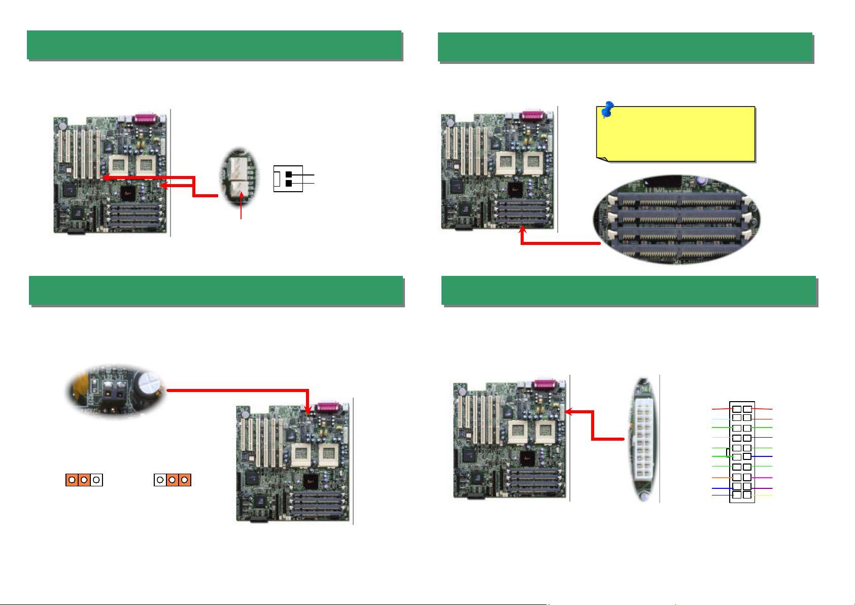
3. Installing Thermal Sensor
Connector (CN7 & CN25) provides you to use the thermal sensor
GND
Sensor
1 1
chipset only allows you using the
1 20 19 13
pins ATX power connector. Make sure you plug the connector in
5. Install DIMM Modules
The Thermal Sens or
to detect the temperature of the components on the motherboard.
Thermal Sensor connector
4. JP10 CPU Terminator Jumper
When you are using SINGLE Intel® Pentium!!! CPU with DX3R Plus, you must
the pin1-2 and install the CPU terminator to the unoccupied socket.
This motherboard has four 168PC133 Registered memory up to 4.0GB.
Note: The ServerSet™ III LE
Registered SRAM with it.
DIMM 1
DIMM 2
DIMM 3
DIMM 4
6. Connecting ATX Power Connector
The DX3R Plus uses 20the right direction.
Dual Processor
Single Processor
(Default)
+3.3V
-12V
COM
PS-ON
COM
COM
COM
-5V
+5V
+5V
+3.3V
+3.3V
COM
+5V
COM
+5V
COM
PWR OK
5VSB
+12V
Page 4

expansibility
watts power supply module
configure
2 14 13
CDA
pin IDE cable to floppy connector FDC and IDE
Be careful of the pin1
pins Narrow SCSI
7. Connecting Redundant SPS Connector
This motherboard implements Redundant SPS connector to provide better
on superior server. It is feasible to install an additional 337(optional) in a hot-swappable redundant configuration , which enables a fullysystem to continue running even if one power module fails.
PS_ON
PS 3 Fail
Fan 3 Fail
2
I
Present 3
GND
Connect 34-pin floppy cable and 40connector. Pin1 of cable is normally marked with red color.
orientation. Wrong orientation may cause system damage.
8. Connecting IDE and Floppy Cables
Pin 1
IDE Master
(1st)
Pin 1
FDD
Connector
IDE Connector
(Primary channel only)
Present 1
I2C CLK
Fan 1 Fail
PS 1 Fail
1
PS 2 Fail
Fan 2 Fail
Present 2
5VSB
IDE Slave
(2nd)
9. Connecting Ultra160 Narrow SCSI Cables
The DX3R Plus provides two 68 -pins Ultra Wide/Ultra2/3 and one 50connectors for 8/16-bit or 16-bit differential SCSI devices.
50-pins
Narrow
SCSI
68-pins
Ultra160
SCSI
10. JP6 SCSI Channel Terminator Control
The JP6 allows you to enable or disable the on-board SCSI terminator control function.
11
On
(Default)
Pin 1
Off
Page 5

11. Connecting Front Panel Connector
Attaching such as power LED, reset switch, power switch connector, etc.… to
To use Wake On LAN function, you must have an Ethernet card with chipset that
re, and connect a cable from LAN card to motherboard WOL
connector. The system identification information (probably IP address) is stored on
network card and because there is a lot of traffic on the Ethernet, you need to install
, such as ADM, for the checking of how to wake up the
Maskable Interrupt used for event handling. When event is occurred, system will
cute a unique task. To disable this function, please short CN18
the
bottom area of this motherboard. With proper cable, you can
ATX
Power LED
Reset Switch
HDD LED
Chassis
1 2 21 22
+5VSB
GND HDD LED
GND +5V +5V PWR LED
HDD LED
+5V INT S/W
RST S/W
GND GND
1 2 21 22
corresponding pins.
Power Switch
Intrusion Switch
13. Support 2nd USB Port
This motherboard supports four USB ports. Two of them are on back panel connector,
other two are on the leftconnect them to front panel.
12. WOL (Wake on LAN) Connector
supports this featu
network management software
system.
USBPWR6
USBP2-
USBP2+ USBP3+
USBPWR8 USBP3-
GND USBPWR5
GND
USBPWR7
14. NMI (Non-Maskable Interrupt) Switch Jumper
Nonreceive an NMI and exe
by jumper cap.
+5VSB
GND
LID
Close
Open
(Default)
Page 6

back plane to ASM (Advanced
such as storage category, HDD
pins
15. BP (Backplane) Connector
After you finish the setting of jumpers and connect correct cables. Power on and
ST (Power On Self Test). Choose
Turbo Defaults", unless you are sure your
system components (CPU, DRAM, HDD,
+5V
The DX3R Plus BIOS supports the system monitored event logs recording function. If
Event LED
will keep flash to warn you.
The BP connector provides the signals of BPL6 / BPL5
Server Management) software monitoring program,
fault, fan present, and fan fault.
17. Event LED Connector
there is any event happens or hard disk fails when you operate your system, the
Pin 1
GND
1
N/C
I2C CLK
I2CDA
16. External Speaker Connector
If you want to use external case-mounted speaker instead of internal buzzer , the 4external speaker connector can let you connect with external case -mounted speaker.
Pin 1
Pin 1
1
To LED
GND
18. Power-On and Load BIOS Setup
enter the BIOS Setup, press <Del> during PO
"Load Default Setting" for recommended optimal performance.
Del
GND
N/C
N/C
Warning: Please avoid of using "Load
etc.) are good enough for turbo setting.
Page 7

If you encou
nter any trouble to boot you system, follow the
The Part Number and Serial number are printed on bar code label. You can find this
bar code label on the outside packing, on ISA/CPU slot or on component side of PCB.
The problem was probably caused
by power supply or motherboard
failure. Please contact your reseller
Perhaps your VGA card or monitor
It is very possible that your keyboard
During system rebooting, press Del to enter BIOS Setup. Choose
caused by the
C power cable, then remove all
of the addon cards and cables, including VGA, IDE, FDD, COM1,
No
procedures accordingly to resolve the problem.
Turn off the power and unplug the A
COM2 and Printer.
Make sure if the jumper settings for CPU and DRAMs are correct.
Install the VGA card. Then connect your monitor and keyboard.
Start
Clear CMOS.
Part Number and Serial Number
For example:
P/N: 91.88110.201 is part number, S/N: 91949378KN73 is serial number.
Turn on the power, and check if
the power supply and CPU fan
work properly.
Check if there is display.
Press Ctrl, and Alt key at the
same time, hold them and then
press Del to see if the
system reboots.
“Load Setup Default".
Turn off the system and
re-connect the IDE cable.
Check if the system can
reboot successfully.
Re-install Windows 95, Windows 98 or Windows NT.
Yes
Yes
Yes
Yes
End
No
or local distributor for repairing.
No
is defective.
is defective.
No
The problem should be
IDE cables or HDD itself.
Page 8

Web Site:
Dear Customer,
Thanks for choosing AOpen products. To provide the best and fastest service to
our customer is our first priority. However, we receive numerous emails and
phone-calls worldwide everyday, it is very hard for us to serve everyone on time.
We recommend you follow the procedures below and seek help before contact
us. With your help, we can then continue to provide the best quality service to
more customers.
Thanks very much for your understanding!
AOpen Technical Supporting Team
1
1
Online Manual: Please check the manual carefully and make sure the
jumper settings and installation procedure are correct.
http://www.aopen.com/tech/download/manual/default.htm
Test Report: We recommend to choose board/card/device from the
compatibility test reports for assembling your PC.
http://www.aopen.com/tech/report/default.htm
F AQ: The latest FAQ (Frequently Asked Questions) may contain a
solution to your problem.
http://www.aopen.com/tech/faq/default.htm
3
3
2
2
Pacific Rim
AOpen Inc.
Tel: 886-2-2696-1333
Fax: 886-2-8691-2233
China
艾????上海(股)有限公司
Tel: 49-2102-157700
Fax: 49-2102-157799
America
AOpen America Inc.
Tel: 1-510-498-8928
Fax: 1-408-922-2935, 1-408-432-0496
www.aopen.com
E-mail: Send us email by going through the contact form below.
English http://www.aopen.com.tw/tech/contact/techusa.htm
Japanese http://www.aopen.co.jp/tech/contact/techjp.htm
Chinese http://www.aopen.com.tw/tech/contact/techtw.htm
German http://www.aopencom.de/tech/contact/techde.htm
French http://france.aopen.com.tw/tech/contact/techfr.htm
Simplified Chinese http://www.aopen.com.cn/tech/contact/techcn.htm
Europe
AOpen Computer b.v.
Tel: 31-73-645-9516
Fax: 31-73-645-9604
Germany
AOpen Computer GmbH.
Tel: 49-2102-157700
Fax: 49-2102-157799
5
5
Download Software: Check out this table to get the latest updated
4
4
News Group: Your problem probably had been answered by our support
engineer or professional users on the news group.
http://www.aopen.com/tech/newsgrp/default.htm
7
7
BIOS/utility and drivers.
http://www.aopen.com/tech/download/default.htm
Contact Distributors/Resellers: We sell our products through resellers
6
6
and integrators. They should know your system configuration very well and
should be able to solve your problem more efficien n important reference for
you if next time you want to buy something else from them.
Contact Us : Please prepare detail system configuration and error symptom
before contacting us. The part number, serial number and BIOS version
are also very helpful.
 Loading...