

Page 1

FFoorrttrreessss 77770000//77990000 OOnnlliinnee MMaannuuaall
DOC. NO. : DX37PU-OL-E0112B
Instr
uction
Installation
Utilit
y
Utilit
y
Tech
nical su
Ho
using
Hardware
BIOS Setup
SCSISelect™
G
lossary &
pport
A
Open
1
Page 2

FFoorrttrreessss 77770000//77990000 OOnnlliinnee MMaannuuaall
Copyright© 2001 AOpen Incorporated
All Rights Reserved.
AOpen Fortress 7700/7900
User’s Guide
Changes may be made periodically to the information in this publication without obligation to notify any person of such revision or
changes. Such changes will be incorporated in new editions of this manual or supplementary documents and publications. This
company makes no representations or warranties either expressed or implied, with respect to the contents hereof and specifically
disclaims the implied warranties of merchantability or fitness for a particular purpose.
No part of this publication may be reproduced., stored in a retrieval system, or transmitted, in any form or by any means, electronic,
mechanical, photocopy, recording, or otherwise, without the prior written permission of Aopen Incorporated.
All brand and product names mentioned in this manual are trademarks and/or registered trademarks of their respective companies.
A
Open
2
Page 3

FFoorrttrreessss 77770000//77990000 OOnnlliinnee MMaannuuaall
IImmppoorrttaanntt SSaaffeettyy IInnssttrruuccttiioonnss
1. Read these instructions carefully. Save these instructions for future reference.
2. Follow all warnings and instructions marked on the product.
3. Do not use this product near water.
4. Do not place this product on an unstable cart, stand, or table. The product may fall, causing serious damage to the product.
5. Slots and openings in the cabinet and the back or bottom are provided for ventilation; to ensure reliable operation of the product
and to protect it from overheating, these openings must not be blocked or covered. The openings should never block by placing the
product on a bed, sofa, rug, or other similar surface. This product should never be placed near or over a radiator or heat register, or
in a built-in installation unless proper ventilation is provided.
6. This product should be operated from the type of power indicated on the marking label. If you are not sure of the type of power
available, consult your dealer or local power company.
7. This product is equipped with a 3-wire grounding-type plug, a plug having a third (grounding) pin. This plug will only fit into a
grounding-type power outlet. This is a safety feature. If you are unable to insert the plug into the outlet, contact your electrician to
replace your obsolete outlet. Do not defeat the purpose of the grounding-type plug.
8. Do not allow anything to rest on the power cord. Do not locate this product where persons will walk on the cord.
9. If an extension cord is used with this product, make sure that the total ampere rating of the equipment plugged into the extension
cord does not exceed the extension cord ampere rating. Also, make sure that the total rating of all products plugged into the wall
outlet does not exceed 15 amperes.
10. Never push objects of any kind into this product through cabinet slots as they may touch dangerous voltage points or short out
parts that could result in a fire or electric shock. Never spill liquid of any kind on the product.
11. Do not attempt to service this product yourself, as opening or removing covers may expose you to dangerous voltage points or
other risks. Refer all servicing to qualified service personnel.
A
3
Open
Page 4

FFoorrttrreessss 77770000//77990000 OOnnlliinnee MMaannuuaall
12. Unplug this product from the wall outlet and refer servicing to qualified service personnel under the following conditions:
a. When the power cord or plug is damaged or frayed
b. If liquid has been spilled into the product
c. If the product has been exposed to rain or water
d. If the product does not operate normally when the operating instructions are followed. Adjust only those controls that are
covered by the operating instructions since improper adjustment of other controls may result in damage and will often
require extensive work by a qualified technician to restore the product to normal condition.
e. If the product has been dropped or the cabinet has been damaged
f. If the product exhibits a distinct change in performance, indicating a need for service
13. Replace the battery with the same type as the product's battery we recommend. Use of another battery may present a risk of fire or
explosion. Refer battery replacement to a qualified serviceman.
14. Warning! The battery could explode if not handled properly. Do not recharge, disassemble or dispose of it in fire. Keep it away
from children and dispose of my used battery promptly.
Use only the proper type of power supply cord set (provided in your keyboard/manual accessories box) for this unit. It should
be a detachable type: UL listed/CSA certified, type SVT/SJT, rated 6A 125V minimum, VDE approved or its equivalent.
Maximum length is 15 feet (4.6 meters).
A
4
Open
Page 5

FFoorrttrreessss 77770000//77990000 OOnnlliinnee MMaannuuaall
CCDD--RROOMM SSaaffeettyy WWaarrnniinngg
DANGER
INVISIBLE RADIATION WHEN OPEN.
AVOID EXPOSURE TO BEAM.
CLASS 1 LASER PRODUCT
APPAREIL A LASER DE CLASSE 1
LASER KLASSE 1
LOUKAN 1 LASERLAITE
PRODUIT LASER
CATEGORIE 1
A
5
Open
Page 6

FFoorrttrreessss 77770000//77990000 OOnnlliinnee MMaannuuaall
CCaauuttiioonn oonn LLiitthhiiuumm BBaatttteerriieess
CAUTION:
Danger of explosion if battery is incorrectly replaced. Replace only with the same or equivalent type recommended by the manufacturer.
Discard used batteries according to the manufacturer’s instructions.
FFCCCC CCllaassss BB RRaaddiioo FFrreeqquueennccyy IInntteerrffeerreennccee SSttaatteemmeenntt
Note:
This equipment has been tested and found to comply with the limits for a Class B digital device, pursuant to Part 15 of FCC Rules.
These limits are designed to provide reasonable protection against harmful interference in a residential installation. This equipment
generates, uses, and can radiate radio frequency energy and, if not installed and used in accordance with the instructions, may cause
harmful interference to radio communications. However, there is no guarantee that interference will not occur in a particular installation.
If this equipment does cause harmful interference to radio or television reception, which can be determined by turning the equipment off
and on, the user is encouraged to try to correct the interference by one or more of the following measures:
1. Reorient or relocate the receiving antenna.
2. Increase the separation between the equipment and receiver.
3. Connect the equipment into an outlet on a circuit different from that to which the receiver is connected.
4. Consult the dealer or an experienced radio/television technician for help.
Notice 1:
The changes or modifications not expressly approved by the party responsible for compliance could void the user's authority to operate
the equipment.
A
6
Open
Page 7

FFoorrttrreessss 77770000//77990000 OOnnlliinnee MMaannuuaall
Notice 2:
Shielded interface cables, if any, must be used in order to comply with the emission limits.
AAbboouutt tthhiiss MMaannuuaall
Purpose
This user’s guide aims to give you the information you need to operate the system properly and tells you how to install internal
components.
Manual Structure
This user’s guide consists of four chapters.
Chapter 1 Fortress 7700/7900 Housing (SV320)
This chapter describes the housing and all its major components. It contains instructions for upgrade options and installation
procedures.
Chapter 2 Fortress 7700/7900 Motherboard (DX37 Plus-U / DX37-U)
This chapter describes the motherboard and all its major components. It contains the motherboard layout, jumper settings,
cache and memory configurations, and information on other internal devices.
Chapter 3 BIOS Setup Utility
This chapter gives information about the system BIOS and tells how to configure the system by changing the settings of the
BIOS parameters.
Chapter 4 SCSI Select Configuration Utility
This chapter gives information about the SCSI Select utility and tells how to configure the SCSI configuration by changed the
settings of the SCSI parameters.
A
7
Open
Page 8
FFoorrttrreessss 77770000//77990000 OOnnlliinnee MMaannuuaall
CCoonnvveennttiioonnss
The following conventions are used in this manual:
Text entered by user Represents text input by the user.
, , , etc….
Represent the actual keys that you have to
press on the keyboard.
NOTE
Gives bits and pieces of additional
information related to the current topic.
CAUTION
Gives precautionary measures to avoid
possible hardware or software problems.
IMPORTANT
Reminds you to take specific actions
relevant to the accomplishment of
procedures.
A
8
Open
Page 9

FFoorrttrreessss 77770000//77990000 OOnnlliinnee MMaannuuaall
WWhhaatt’’ss iinn tthhiiss mmaannuuaall
Fortress 7700/7900 …………………………………………………………………………………………………………………………………..1
I
MPORTANT SAFETY INSTRUCTIONS ..............................................................................................................................................................................3
CD-ROM SAFETY WARNING ........................................................................................................................................................................................ 5
CAUTION ON LITHIUM BATTERIES................................................................................................................................................................................. 6
FCC CLASS B RADIO FREQUENCY INTERFERENCE STATEMENT.................................................................................................................................... 6
ABOUT THIS MANUAL ...................................................................................................................................................................................................7
CONVENTIONS............................................................................................................................................................................................................... 8
WHAT’S IN THIS MANUAL .............................................................................................................................................................................................. 9
CHAPTER 1 HOUSING INSTRUCTION (SV320) .................................................................................................................................................. 20
1.1 INTRODUCTION......................................................................................................................................................................................................20
1.2 STANDALONE SYSTEM...........................................................................................................................................................................................20
1.3.1 Front Panel .................................................................................................................................................................................................... 21
1.3.2 Rear Panel ..................................................................................................................................................................................................... 22
1.3.3 Internal Structure ...........................................................................................................................................................................................23
1.4 OPENING THE HOUSING PANELS ............................................................................................................................................................................24
1.4.1 Front Panel .................................................................................................................................................................................................... 24
1.4.2 Left Panel ....................................................................................................................................................................................................... 25
1.5 INSTALLING DEVICE DRIVES .................................................................................................................................................................................26
A
9
Open
Page 10

FFoorrttrreessss 77770000//77990000 OOnnlliinnee MMaannuuaall
1.5.1 3.5-inch Device Drive .................................................................................................................................................................................... 26
1.5.2 5.25-inch Device Drives.................................................................................................................................................................................28
1.6 INSTALLING HOT-SWAP CAGES..............................................................................................................................................................................30
1.6.1 Installing a HSC5 Hot-Swap Cage................................................................................................................................................................. 30
1.6.2 Installing and Removing a HSC5 Hard Disk Drive Tray................................................................................................................................ 33
1.6.3 HSC5 LVD SCSI Backpanel Board ................................................................................................................................................................34
1.6.4 HSC5 Jumpers and Connectors......................................................................................................................................................................35
1.7 INSTALLING AND REMOVING A HOT-SWAPPABLE REDUNDANT POWER SUPPLY MODULE ......................................................................................38
1.8 INSTALLING AN EXTERNAL REDUNDANT SYSTEM FAN (OPTIONAL)...................................................................................................................... 41
1.9 INSTALLING A MOTHERBOARD .............................................................................................................................................................................. 43
1.10 INSTALLING AN EXPANSION CARD .......................................................................................................................................................................44
CHAPTER 2 HARDWARE INSTALLATION.......................................................................................................................................................... 45
2.1 OVERVIEW .............................................................................................................................................................................................................45
2.2 FEATURE HIGHLIGHT .............................................................................................................................................................................................46
CPU ........................................................................................................................................................................................................................ 46
Chipset.................................................................................................................................................................................................................... 46
Memory................................................................................................................................................................................................................... 46
Expansion Slots.......................................................................................................................................................................................................46
SCSI On-board (DX37 Plus-U only).......................................................................................................................................................................47
10
A
Open
Page 11

FFoorrttrreessss 77770000//77990000 OOnnlliinnee MMaannuuaall
Ultra DMA 33/66/100 Bus Mater IDE....................................................................................................................................................................47
Intel 82550 LAN controller ..................................................................................................................................................................................... 47
Power Management/Plug and Play......................................................................................................................................................................... 48
Hardware Monitoring Management........................................................................................................................................................................48
Super Multi-I/O.......................................................................................................................................................................................................48
2.3 MOTHERBOARD MAP ............................................................................................................................................................................................ 49
2.4 BLOCK DIAGRAM ..................................................................................................................................................................................................50
2.5 CONNECTORS AND JUMPERS.................................................................................................................................................................................. 51
2.6 HARDWARE ...........................................................................................................................................................................................................53
2.6.2 CPU Installation ............................................................................................................................................................................................ 55
2.6.3 CPU & System Fan Connector.......................................................................................................................................................................56
2.6.4 Supported CPU Type...................................................................................................................................................................................... 57
2.6.5 Setting CPU Voltage and Frequency ..............................................................................................................................................................58
2.6.6 DIMM Socket ................................................................................................................................................................................................. 60
22..66..66..11 HHooww ttoo IInnssttaallll MMeemmoorryy MMoodduullees
2.6.7 ATX Power Connector and AGP Pro Power Connector .................................................................................................................................62
2.6.8 Redundant SPS Monitoring Connector .......................................................................................................................................................... 63
2.6.9 IDE and Floppy Connector ............................................................................................................................................................................64
2.6.10 68-pin Ultra 160 SCSI Connector (DX37 Plus-U only)................................................................................................................................67
2.6.11 Front Panel Connector.................................................................................................................................................................................68
s ................................................................................................................................................................. 61
11
A
Open
Page 12

FFoorrttrreessss 77770000//77990000 OOnnlliinnee MMaannuuaall
2.6.12 WOL (Wake on LAN)....................................................................................................................................................................................69
2.6.13 Support 4 USB Connectors...........................................................................................................................................................................71
2.6.14 SCSI LED Connector (For SCSI/RAID Card, DX37 Plus-U Only)..............................................................................................................72
2.6.15 CD/AUX Connector .....................................................................................................................................................................................73
2.6.16 PC99 Color Coded Back Panel....................................................................................................................................................................74
2.6.17 Support 10/100 Mbps LAN onboard.............................................................................................................................................................75
2.6.18 Low ESR Capacitor...................................................................................................................................................................................... 76
CHAPTER 3 BIOS SETUP UTILITY ....................................................................................................................................................................... 77
3.1 ENTERING SETUP...................................................................................................................................................................................................78
3.2 SYSTEM INFORMATION ..........................................................................................................................................................................................80
3.2.1 Processor .......................................................................................................................................................................................................80
3.2.2 Processor Speed ............................................................................................................................................................................................. 81
3.2.3 CPU/SDRAM BUS Frequency........................................................................................................................................................................ 81
3.2.4 Level 1 Cache................................................................................................................................................................................................. 81
3.2.5 Level 2 Cache................................................................................................................................................................................................. 81
3.2.6 Diskette Drive A.............................................................................................................................................................................................81
3.2.7 Diskette Drive B.............................................................................................................................................................................................81
3.2.8 IDE Primary Channel Master........................................................................................................................................................................82
3.2.9 IDE Primary Channel Slave...........................................................................................................................................................................82
12
A
Open
Page 13

FFoorrttrreessss 77770000//77990000 OOnnlliinnee MMaannuuaall
3.2.10 IDE Secondary Channel Master................................................................................................................................................................... 82
3.2.11 IDE Secondary Channel Slave......................................................................................................................................................................82
3.2.12 Total Memory ...............................................................................................................................................................................................82
3.2.13 Serial Port 1 ................................................................................................................................................................................................. 83
3.2.14 Serial Port 2 ................................................................................................................................................................................................. 83
3.2.15 Parallel Port ................................................................................................................................................................................................83
3.2.16 PS/2 Mouse ..................................................................................................................................................................................................83
3.3 PRODUCT INFORMATION ........................................................................................................................................................................................84
3.3.1 Product Name ................................................................................................................................................................................................84
3.3.2 System S/N......................................................................................................................................................................................................85
3.3.3 Main Board ID............................................................................................................................................................................................... 85
3.3.4 Main Board S/N.............................................................................................................................................................................................. 85
3.3.5 System BIOS Version ......................................................................................................................................................................................85
3.3.6 SMBIOS Version.............................................................................................................................................................................................85
3.4 DISK DRIVES .........................................................................................................................................................................................................86
3.4.1 Floppy Drives................................................................................................................................................................................................. 86
3.4.2 IDE Drives ..................................................................................................................................................................................................... 87
3.5 ONBOARD PERIPHERALS .......................................................................................................................................................................................90
3.5.1 Serial Ports 1 and 2........................................................................................................................................................................................ 90
3.5.2 Parallel Port .................................................................................................................................................................................................. 92
13
A
Open
Page 14

FFoorrttrreessss 77770000//77990000 OOnnlliinnee MMaannuuaall
3.5.3 Onboard Device Settings................................................................................................................................................................................94
3.6 POWER MANAGEMENT .......................................................................................................................................................................................... 98
3.6.1 Power Management Mode..............................................................................................................................................................................99
3.6.2 Power Switch < 4 sec................................................................................................................................................................................... 100
3.6.3 System Wake-up Event.................................................................................................................................................................................. 101
3.7 BOOT OPTIONS .................................................................................................................................................................................................... 103
3.7.1 Boot Sequence .............................................................................................................................................................................................. 104
3.7.2 Fast Boot......................................................................................................................................................................................................104
3.7.3 Silent Boot .................................................................................................................................................................................................... 105
3.7.4 Num Lock After Boot.................................................................................................................................................................................... 105
3.7.5 Memory Test ................................................................................................................................................................................................. 106
3.7.6 Release All Blocked Memory........................................................................................................................................................................106
3.8 DATE AND TIME ...................................................................................................................................................................................................107
3.8.1 Date ............................................................................................................................................................................................................. 108
3.8.2 Time.............................................................................................................................................................................................................. 108
3.9 SYSTEM SECURITY ..............................................................................................................................................................................................109
3.9.1 Supervisor Password.................................................................................................................................................................................... 110
3.9.2 User Password ..............................................................................................................................................................................................111
3.9.3 Disk Drive Control........................................................................................................................................................................................111
14
A
Open
Page 15

FFoorrttrreessss 77770000//77990000 OOnnlliinnee MMaannuuaall
3.9.4 Processor Serial Number .............................................................................................................................................................................112
3.10 SYSTEM EVENT LOG..........................................................................................................................................................................................113
3.10.1 System Event Logging ................................................................................................................................................................................114
3.10.2 Events Control............................................................................................................................................................................................ 115
3.10.3 Event Process............................................................................................................................................................................................. 116
3.11 LOAD DEFAULT SETTINGS ................................................................................................................................................................................. 117
3.12 ABORT SETTINGS CHANGE ................................................................................................................................................................................ 118
CHAPTER 4 SCSISELECT™ UTILITY (DX37 PLUS-U ONLY).........................................................................................................................119
Settings for the SCSI Controller and All Devices .................................................................................................................................................. 119
Individual Settings for SCSI Drives.......................................................................................................................................................................120
When to Use the SCSISelect™ Utility ...................................................................................................................................................................120
4.1 RUNNING THE SCSISELECT™ UTILITY (DX37 PLUS-U ONLY)........................................................................................................................... 121
4.2 UTILITY OPTIONS ................................................................................................................................................................................................ 122
4.2.1 Configuring Channel A ................................................................................................................................................................................122
4.3 CONFIGURE/VIEW HOST ADAPTER SETTINGS MENU........................................................................................................................................... 125
4.3.1 Host Adapter SCSI ID..................................................................................................................................................................................126
4.3.2 SCSI Parity Checking................................................................................................................................................................................... 128
4.3.3 Boot Device Options ....................................................................................................................................................................................129
4.3.4 Boot Channel Options..................................................................................................................................................................................130
4.3.5 Boot SCSI ID Options ..................................................................................................................................................................................131
15
A
Open
Page 16

FFoorrttrreessss 77770000//77990000 OOnnlliinnee MMaannuuaall
4.3.6 Boot LUN Number Options..........................................................................................................................................................................132
4.3.7 Boot LUN Number ....................................................................................................................................................................................... 133
4.4 ADVANCED CONFIGURATION OPTIONS ................................................................................................................................................................137
4.4.1 Host Adapter BIOS....................................................................................................................................................................................... 138
4.4.2 Display <Ctrl-A> Message During BIOS Initialization...............................................................................................................................138
4.4.3 Extended BIOS Translation for DOS Drives > 1 GByte ............................................................................................................................... 138
4.4.4 Support Removable Disks Under BIOS as Fixed Disks ................................................................................................................................ 139
4.4.5 BIOS Support for Bootable CD-ROM .......................................................................................................................................................... 140
4.4.6 BIOS Support for Int13 Extensions .............................................................................................................................................................. 140
4.5 SCSI DISK UTILITIES (DX37 PLUS-U ONLY).......................................................................................................................................................141
4.5.1 Format Disk .................................................................................................................................................................................................143
4.5.2 Verify Media................................................................................................................................................................................................. 143
4.6 DISK DRIVES OVER 1 GBYTE.............................................................................................................................................................................. 144
4.6.1 Extended Translation....................................................................................................................................................................................144
4.6.2 DOS 1 GByte Limit.......................................................................................................................................................................................144
4.7 WHEN TO USE THE EXTENDED TRANSLATION ..................................................................................................................................................... 145
4.7.1 with DOS 5.0 and above............................................................................................................................................................................... 145
4.7.2 drives with mixed partitions ......................................................................................................................................................................... 145
4.7.3 Using FDISK................................................................................................................................................................................................ 145
16
A
Open
Page 17

FFoorrttrreessss 77770000//77990000 OOnnlliinnee MMaannuuaall
GLOSSARY ................................................................................................................................................................................................................146
AC97 ........................................................................................................................................................................................................................146
ACPI (ADVANCED CONFIGURATION & POWER INTERFACE) .....................................................................................................................................146
AGP (ACCELERATED GRAPHIC PORT) .......................................................................................................................................................................146
AMR (AUDIO/MODEM RISER) .................................................................................................................................................................................. 147
AOPEN BONUS PACK CD ..........................................................................................................................................................................................147
APM .........................................................................................................................................................................................................................147
ATA/66......................................................................................................................................................................................................................147
ATA/100....................................................................................................................................................................................................................147
BIOS (BASIC INPUT/OUTPUT SYSTEM)..................................................................................................................................................................... 148
BUS MASTER IDE (DMA MODE)...............................................................................................................................................................................148
CODEC (CODING AND DECODING)...........................................................................................................................................................................148
DIMM (DUAL IN LINE MEMORY MODULE) ..............................................................................................................................................................148
ECC (ERROR CHECKING AND CORRECTION)............................................................................................................................................................. 149
EDO (EXTENDED DATA OUTPUT) MEMORY.............................................................................................................................................................. 149
EEPROM (ELECTRONIC ERASABLE PROGRAMMABLE ROM) ..................................................................................................................................149
EPROM (ERASABLE PROGRAMMABLE ROM).......................................................................................................................................................... 149
EV6 BUS ................................................................................................................................................................................................................... 150
FCC DOC (DECLARATION OF CONFORMITY)............................................................................................................................................................150
FC-PGA.................................................................................................................................................................................................................... 150
17
A
Open
Page 18

FFoorrttrreessss 77770000//77990000 OOnnlliinnee MMaannuuaall
FLASH ROM..............................................................................................................................................................................................................150
FSB (FRONT SIDE BUS) CLOCK ................................................................................................................................................................................151
I2C BUS .....................................................................................................................................................................................................................151
P1394........................................................................................................................................................................................................................ 151
PAR ITY BIT................................................................................................................................................................................................................ 151
PBSRAM (PIPELINED BURST SRAM) ......................................................................................................................................................................151
PC100 DIMM........................................................................................................................................................................................................... 152
PC133 DIMM........................................................................................................................................................................................................... 152
PDF FORMAT ............................................................................................................................................................................................................ 152
PNP (PLUG AND PLAY) .............................................................................................................................................................................................. 152
POST (POWER-ON SELF TEST) ................................................................................................................................................................................. 152
RDRAM (RAMBUS DRAM) .....................................................................................................................................................................................153
RIMM....................................................................................................................................................................................................................... 153
SDRAM (SYNCHRONOUS DRAM) ...........................................................................................................................................................................153
SIMM (SINGLE IN LINE MEMORY MODULE).............................................................................................................................................................153
SMBUS (SYSTEM MANAGEMENT BUS) ..................................................................................................................................................................... 154
SPD (SERIAL PRESENCE DETECT)............................................................................................................................................................................. 154
ULT RA DMA/33 ........................................................................................................................................................................................................ 154
USB (UNIVERSAL SERIAL BUS) ................................................................................................................................................................................ 154
18
A
Open
Page 19

FFoorrttrreessss 77770000//77990000 OOnnlliinnee MMaannuuaall
VCM (VIRTUAL CHANNEL MEMORY).......................................................................................................................................................................155
ZIP FILE ....................................................................................................................................................................................................................155
TROUBLESHOOTING ...................................................................................................................................................................................156
TECHNICAL SUPPORT...........................................................................................................................................................................................160
PART NUMBER AND SERIAL NUMBER ..................................................................................................................................................161
PRODUCT REGISTRATION ...................................................................................................................................................................................162
HOW TO CONTACT US...........................................................................................................................................................................................163
19
A
Open
Page 20
FFoorrttrreessss 77770000//77990000 OOnnlliinnee MMaannuuaall
CChhaapptteerr 11 HHoouussiinngg IInnssttrruuccttiioonn ((SSVV332200))
11..11 IInnttrroodduuccttiioonn
This installation guide describes the features of the SV320 housing and tells you how to install the basic system components such as
disk drives, a motherboard, or expansion boards.
11..22 SSttaannddaalloonnee SSyysstteemm
The SV320 housing is designed both as standalone and rackmount system housing. Rotate the feet outward to stabilize it when
placed as standalone housing.1.3 Features
If you receive a complete system, the basic components
are already installed.
20
A
Open
Page 21
FFoorrttrreessss 77770000//77990000 OOnnlliinnee MMaannuuaall
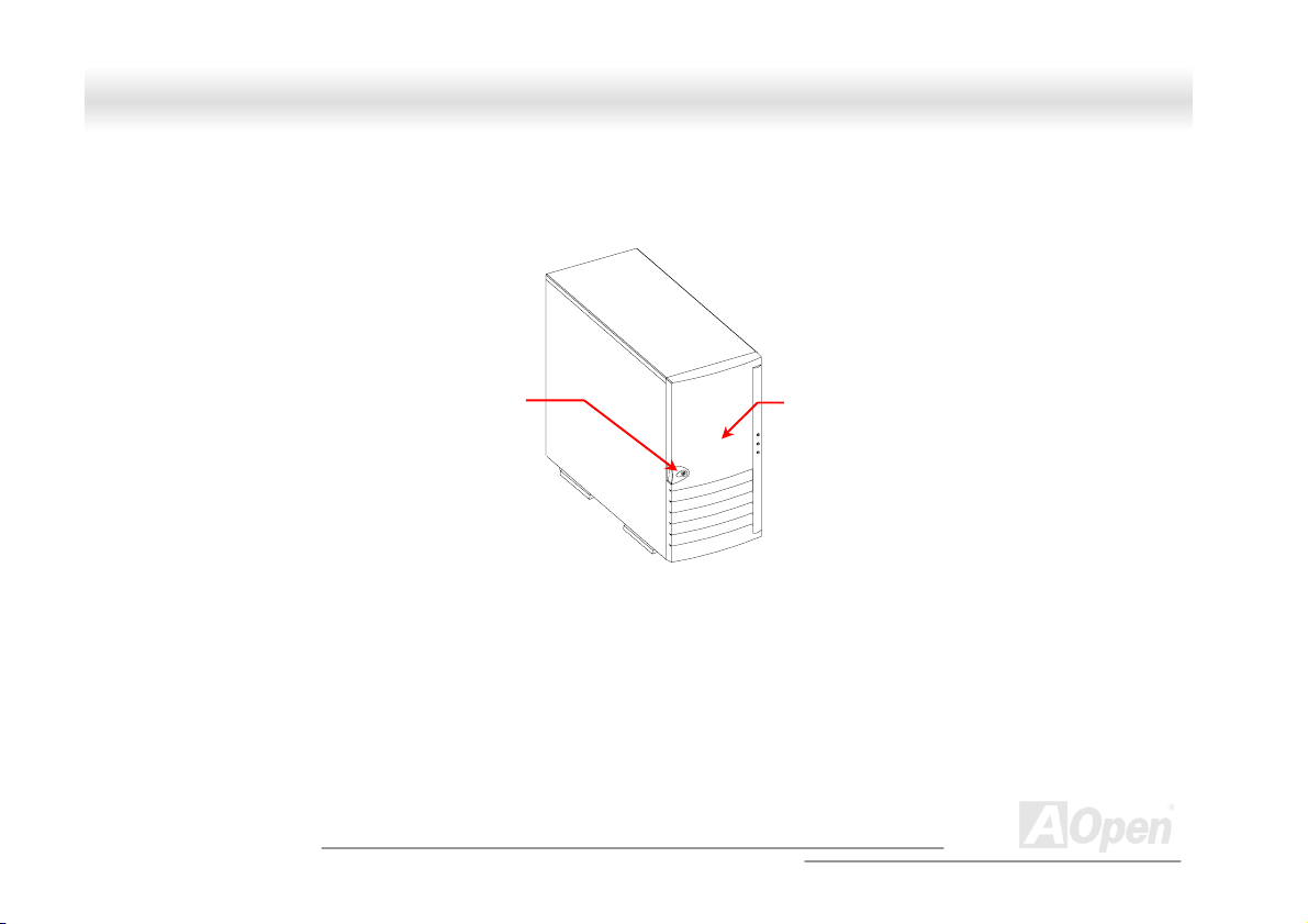
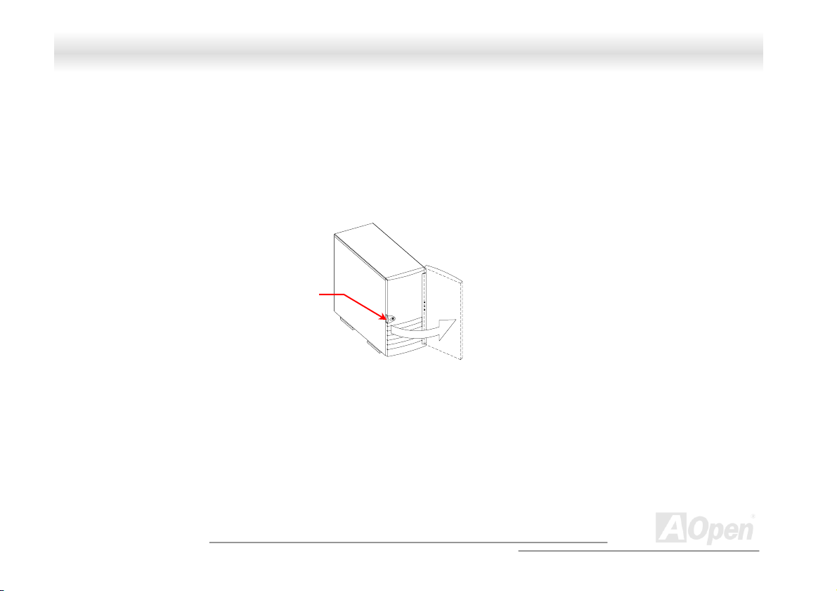
1.3.1 Front Panel
Key lock
21
Panel Door
A
Open
Page 22
FFoorrttrreessss 77770000//77990000 OOnnlliinnee MMaannuuaall
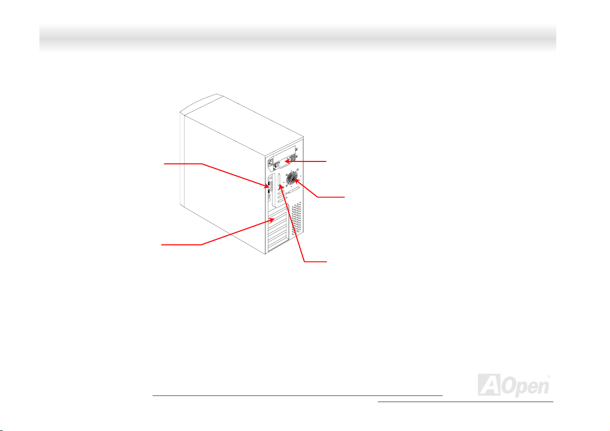
1.3.2 Rear Panel
COM port
Outlets
Expansion Slots
Hot-Swap Redundant
Power Supply
SCSI Expansion Slots
22
Housing Fan
(Optional)
A
Open
Page 23
r
y
d
d
5
-
y
FFoorrttrreessss 77770000//77990000 OOnnlliinnee MMaannuuaall
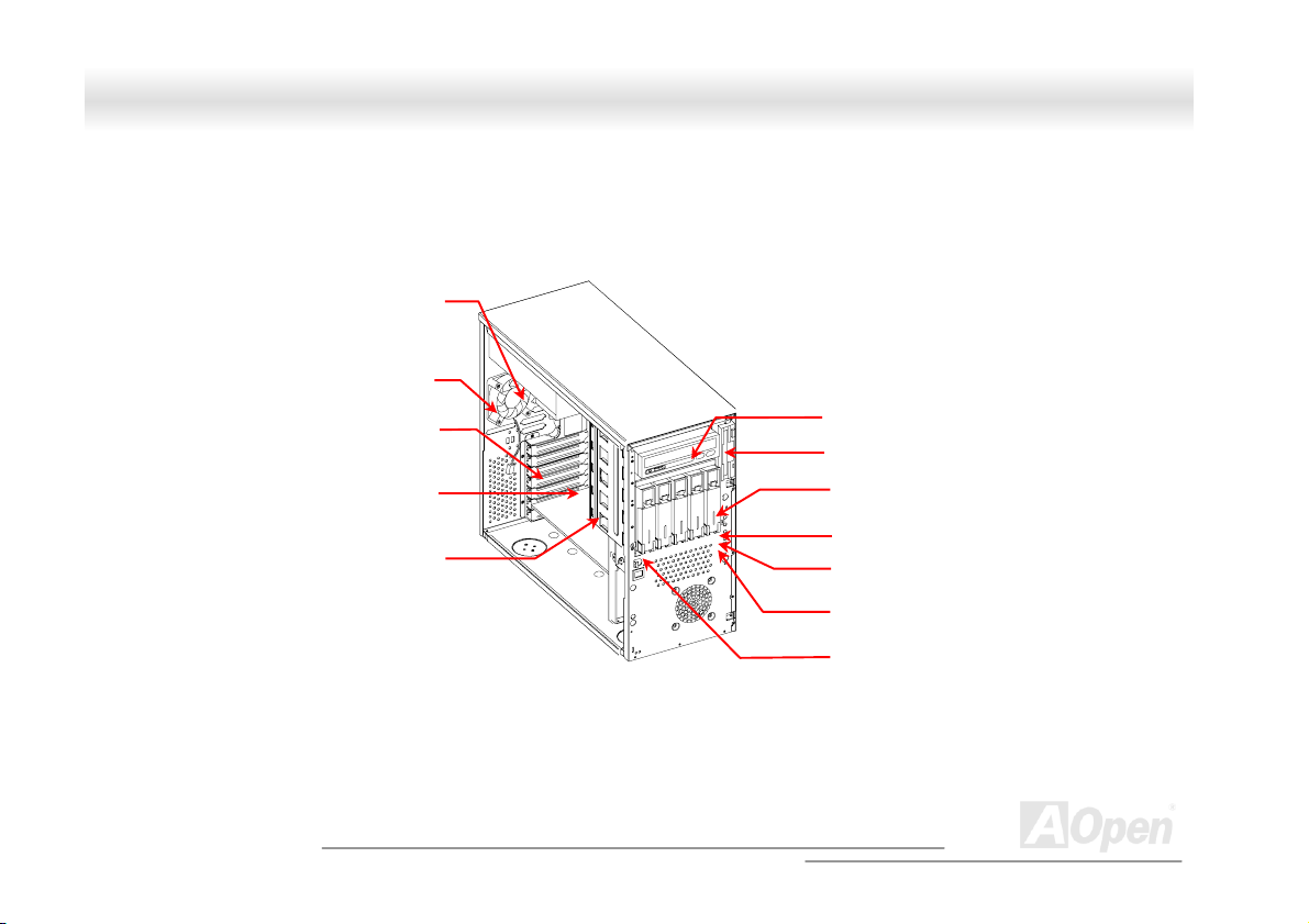
1.3.3 Internal Structure
Redundant Powe
Back-plane Boar
Hot-swap
Suppl
Housing Fan
Expansion Car
Slots
Hot-Swap Cage
(SCSI)
5.25-inch Drive Bays
3.
inch Drive Ba
Power Switch
Power LED
Hard Disk Drive LED
System Status LED
(reserved)
Removable Hard Disk
Drive Trays
A
23
Open
Page 24
k
FFoorrttrreessss 77770000//77990000 OOnnlliinnee MMaannuuaall
11..44 OOppeenniinngg tthhee HHoouussiinngg PPaanneellss
1.4.1 Front Panel
Key loc
To open the front panel, use the key to unlock and then pull the panel as shown in the illustration above.
A
24
Open
Page 25
FFoorrttrreessss 77770000//77990000 OOnnlliinnee MMaannuuaall
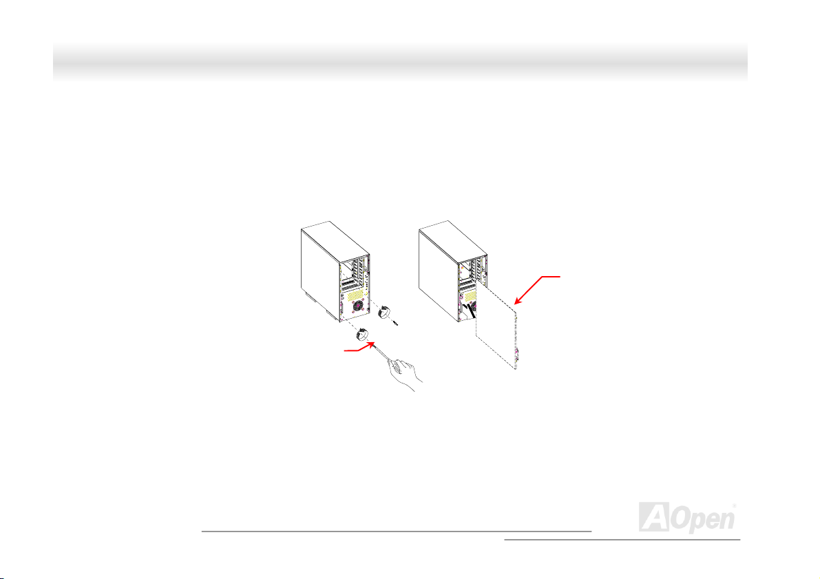
1.4.2 Left Panel
To remove the left panel:
1. Use a screwdriver to remove the two front screws. Keep them in a safe place for later use.
2. Pull the panel handle out and use it to remove the left panel from the housing.
Screw
Left Panel Handle
25
Left panel
A
Open
Page 26
FFoorrttrreessss 77770000//77990000 OOnnlliinnee MMaannuuaall
11..55 IInnssttaalllliinngg DDeevviiccee DDrriivveess
Turn off the power switch and unplug the power cord
before installing or removing diskette drives.
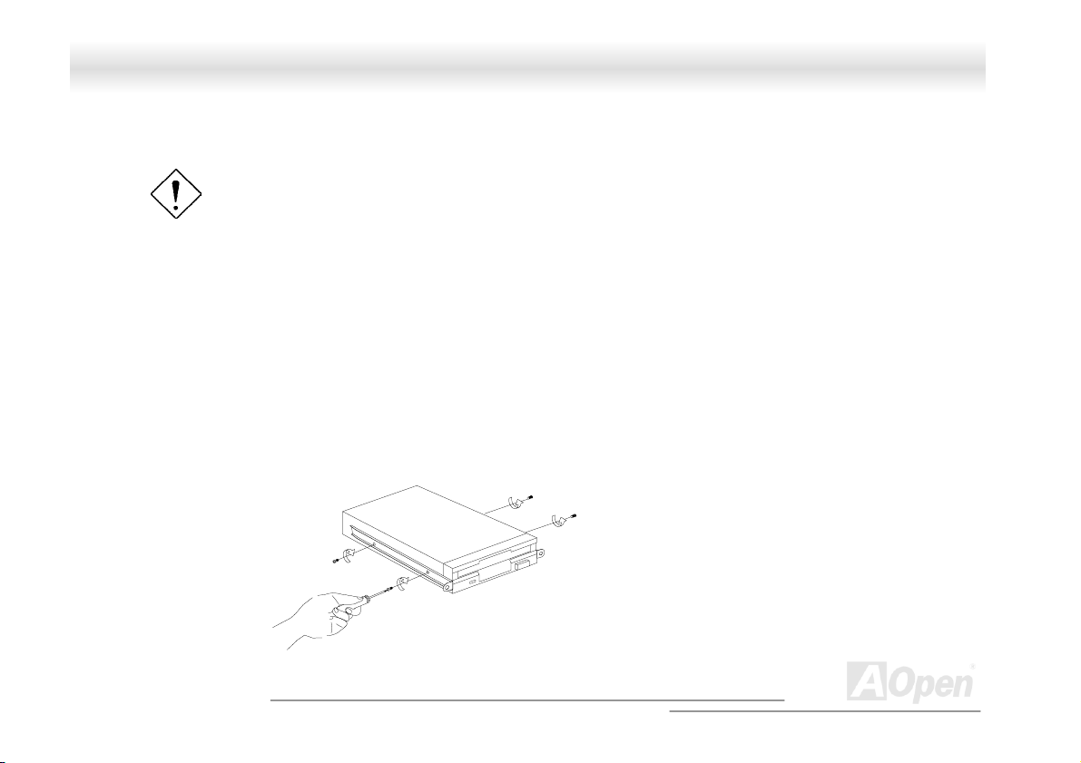
1.5.1 3.5-inch Device Drive
To install 3.5-inch device drives:
1. Open the front panel of the housing. See section 1.4.1 for more information on opening the housing panel.
2. Detached the 3.5-inch drive frame (2 pieces) from the housing by removing two screws. Keep the screws for
later use.
3. Attached the drive frames to the 3.5-inch drive securing it with four screws as shown below.
26
A
Open
Page 27
FFoorrttrreessss 77770000//77990000 OOnnlliinnee MMaannuuaall
4. Insert the drive into the drive bay and secure it with two screws.
5. Connect the diskette drive cables and close the housing panels.
27
A
Open
Page 28
FFoorrttrreessss 77770000//77990000 OOnnlliinnee MMaannuuaall
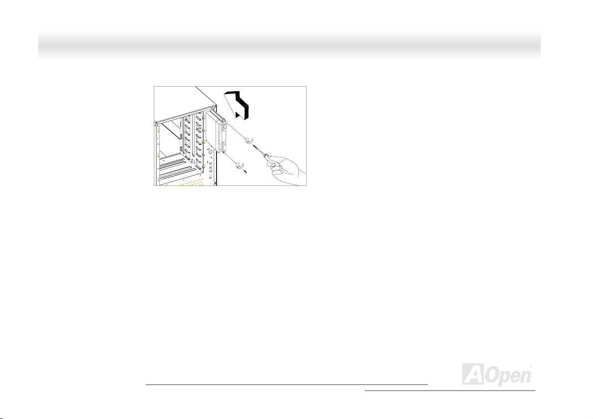
1.5.2 5.25-inch Device Drives
You may install a CD-ROM, digital-audio tape (DAT), hard disk, diskette drive or any other 5.25-inch device into the drive bay.
To install 5.25-inch devices:
1. Open the front panel. See section 1.4.1 for more information on opening the housing panel.
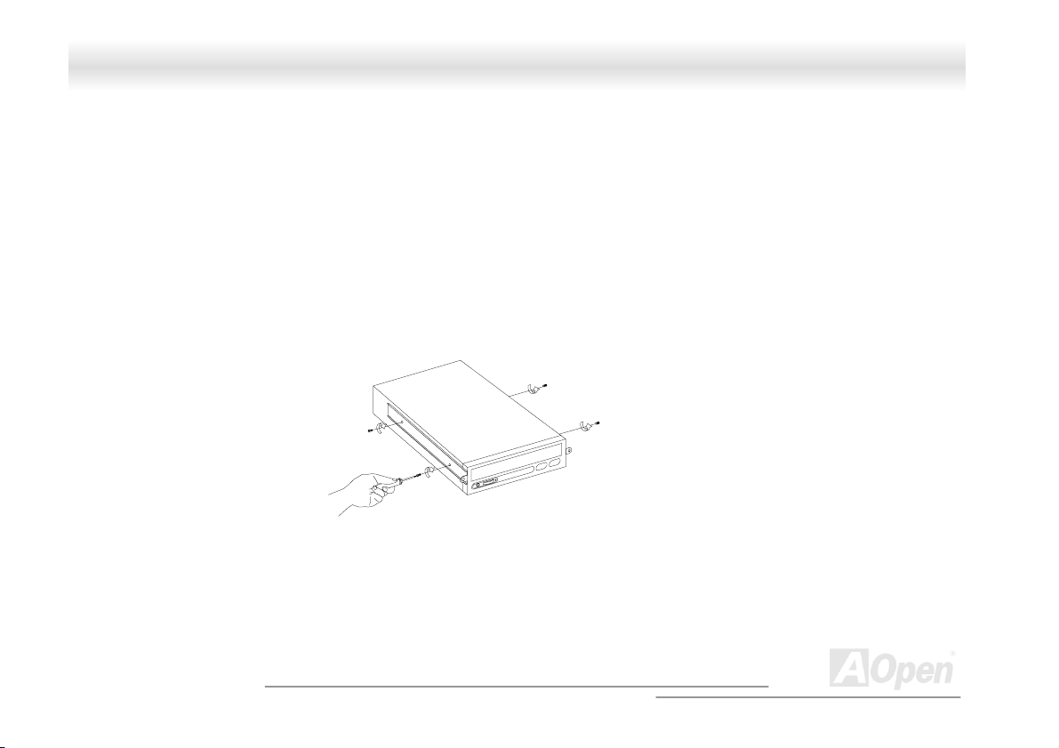
2. Detached the 5.25-inch drive frame (2 pieces) from the housing by removing two screws. Keep the screws for later use.
3. Attached the drive frames to the 5.25-inch device drive securing it with four screws as shown below.
28
A
Open
Page 29
FFoorrttrreessss 77770000//77990000 OOnnlliinnee MMaannuuaall
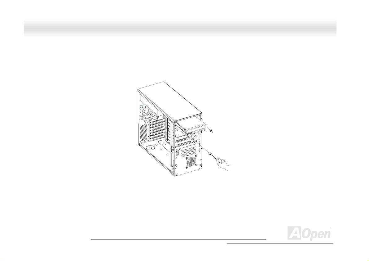
4. Insert the drive into the drive bay and secure it with two screws.
5. Connect the signal and power cables to the drive and close the housing panels.
29
A
Open
Page 30

FFoorrttrreessss 77770000//77990000 OOnnlliinnee MMaannuuaall
11..66 IInnssttaalllliinngg HHoott--SSwwaapp CCaaggeess
The SV320 system housing comes with one HSC5 hot-swap cage. The HSC5 hot-swap cage box includes the following components:
• One hot-swap cage (with back plane board attached)
• Five hard disk drive tray
• One SCSI terminator
1.6.1 Installing a HSC5 Hot-Swap Cage
To install the hot-swap cage into the housing:
1. Open the front panel and remove the left panel of the housing. See section 1.4.1 for more information on opening
the housing panels.
2. Insert the hot-swap cage into the housing and secure the hot-swap cage with two screws as shown below.
30
A
Open
Page 31

FFoorrttrreessss 77770000//77990000 OOnnlliinnee MMaannuuaall
We suggest you use the lower three 5.25” bays.
3. Locate the LVD SCSI cable and remove the terminator located at the end of the LVD SCSI cable.
31
A
Open
Page 32

r
FFoorrttrreessss 77770000//77990000 OOnnlliinnee MMaannuuaall
4. Attach the power cable and the LVD SCSI cable to the backpanel board. The LVD SCSI cable can be
connected to either onboard SCSI channel A or B (channel B recommended), or RAID card to form a RAID
configuration.
SCSI Terminator
Connect to either onboard
SCSI channel A or B
(channel B recommended)
or RAID card
LVD SCSI cable
Power connecto
Connect to the system
power supply
Remove the terminator and
connect to the HSC5 hot-swap
cage
A
32
Open
Page 33

FFoorrttrreessss 77770000//77990000 OOnnlliinnee MMaannuuaall
1.6.2 Installing and Removing a HSC5 Hard Disk Drive Tray
To remove and install a HSC5 Hard Disk Drive Tray:
1. Use your finger to release the drive tray and then
pull it out.
2. Remove all jum
Secure it with fo
pers on the hard disk and place it on the tray.
ur screws.
3. Insert the tray int ke sure that the drive is properly inserted before closing the
lever.
o the hot-swap cage with the lever still extended. Ma
33
A
Open
Page 34

FFoorrttrreessss 77770000//77990000 OOnnlliinnee MMaannuuaall
1.6.3 HSC5 LVD SCSI Backpanel Board
The HSC5 LVD SCSI hot-swap cage supports five 1-inch SCA SCSI hard drives in one channel. The SCA connector design allows for
the addition and removal of SCSI drives without shutting down the system.
34
A
Open
Page 35

FFoorrttrreessss 77770000//77990000 OOnnlliinnee MMaannuuaall
Backpanel Features
The backpanel board has the following major features:
• “Hot-swap” feature that allows replacement of hard drives even when the system is still on.
• Indicates hard disk drive failure through a front panel board LED on cage.
• Supports ultra-2 SCSI SCA (Single Connector Attachment) disk drives.
SCSI ID strapping that allows SCSI HDD ID configuration through the backpanel switches, instead of configuring the individual drive
IDs.
1.6.4 HSC5 Jumpers and Connectors
35
A
Open
Page 36

FFoorrttrreessss 77770000//77990000 OOnnlliinnee MMaannuuaall
Jumper Setting Function
JP1 Short/Open
SW1 & SW2
Connector Description
CN1 SCSI 68-pin connector - Out
CN2 Slot 1
CN3 Slot 2
CN4 Slot 3
CN5 Slot 4
CN6 Slot 5
CN7 Front panel LED connector (reserved)
CN8 SCSI 68-pin connector - In
CN9 Reserved
CN10 HDD fault LED connector (reserved)
JP2 FAN connector
JP31
Terminator Power Source
Both from Backpanel and Host
Only from Host
Reserved
Power connector
36
A
Open
Page 37

FFoorrttrreessss 77770000//77990000 OOnnlliinnee MMaannuuaall
Connector Description
JP4 Power connector
JP5 Reserved
S12
S2 Slot 2 ID switch
S3 Slot 3 ID switch
S4 Slot 4 ID switch
S5 Slot 5 ID switch
1 For HSC5 power loading requirement, please use independent power connectors to connect HSC5. If there is more
than one connector on the same wire, those additional connectors should not be used.
2 Please remove all jumpers on each SCSI hard drive before installing. Use the switches on the backpanel board
(S1~S5) to configure the hard drive? ID.
Slot 1 ID switch
37
A
Open
Page 38

FFoorrttrreessss 77770000//77990000 OOnnlliinnee MMaannuuaall
11..77 IInnssttaalllliinngg aanndd RReemmoovviinngg aa HHoott--sswwaappppaabbllee RReedduunnddaanntt PPoowweerr SSuuppppllyy
MMoodduullee
The power subsystem consists of two hot-swappable power supply module bays that allow the installation of two 337-watts power
supply modules in a hot-swappable redundant configuration. A redundant power configuration enables a fully-configure system to
continue running even if one power supply fails.
To install a hot-swappable redundant power supply, please follow the steps as shown below.
The SV320 comes with one hot-swappable redundant power
supply installed.
38
A
Open
Page 39

FFoorrttrreessss 77770000//77990000 OOnnlliinnee MMaannuuaall
1. Insert the power supply into the housing.
Make sure that the power supply is properly inserted.
2. Secure the power supply with a screw.
39
A
Open
Page 40

FFoorrttrreessss 77770000//77990000 OOnnlliinnee MMaannuuaall
To remove a hot-swappable redundant power supply, please follow the steps as shown below.
1. Using a flat-head screwdriver, turn the screw counter clockwise to loosen the power supply.
2. Push the metal lock towards the power supply as shown below and gently pull out the power supply using the metal handle.
40
The power supply subsystem
should supply a minimum of
337-Watts to the whole
system. If you only have
one power supply or if you
have two power supplies and
are planning to remove both
of them, remember to turn off
the power first and disconnect
the power cord from the
electrical outlet.
A
Open
Page 41

FFoorrttrreessss 77770000//77990000 OOnnlliinnee MMaannuuaall
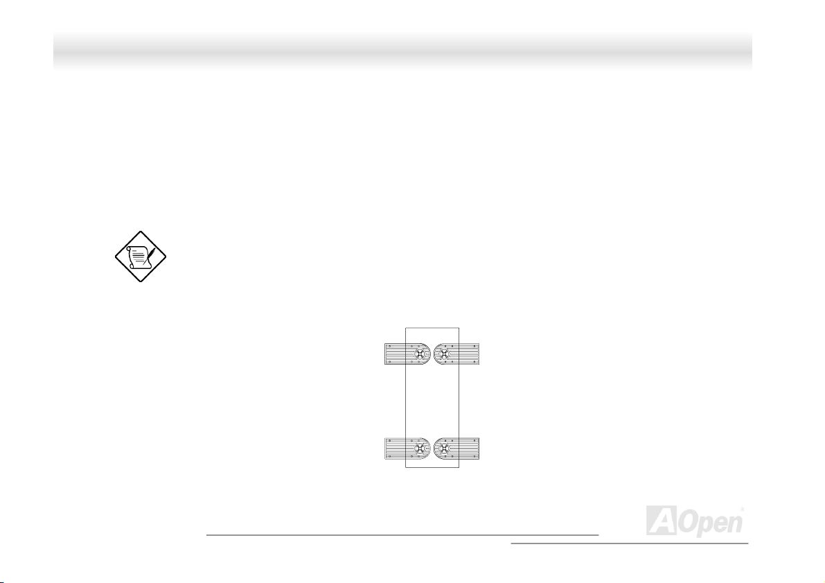
11..88 IInnssttaalllliinngg aann EExxtteerrnnaall RReedduunnddaanntt SSyysstteemm FFaann ((OOppttiioonnaall))
An additional external redundant fan can be installed behind the system housing. This allows the system to operate properly even
though the internal housing fan failed.
To install an external redundant fan:
1. Open the front panel and remove the left panel of the housing. See section 1.4.1 for more information on opening the housing
panels.
2. Use the screwdriver to push open the plastic peg located below the internal system fan module.
3. Insert the redundant fan into the fan cage and attach the fan cage to the system housing with four screws as shown below.
41
A
Open
Page 42

FFoorrttrreessss 77770000//77990000 OOnnlliinnee MMaannuuaall
Redundant Fan
Screw
4. Insert the fan cable into the peg hole and attach the cable to the motherboard. The fan can be connected to the motherboard fan
connector.
42
A
Open
Page 43

d
FFoorrttrreessss 77770000//77990000 OOnnlliinnee MMaannuuaall
11..99 IInnssttaalllliinngg aa MMootthheerrbbooaarrdd
The housing accommodates various motherboard sizes. You can rearrange the stand-offs on the motherboard plate to fit the board
that you wish to install.
Motherboar
Align the motherboard holes to the pegs with the external ports facing the rear of the housing. Secure the board with eight screws.
A
43
Open
Page 44

FFoorrttrreessss 77770000//77990000 OOnnlliinnee MMaannuuaall
11..1100 IInnssttaalllliinngg aann EExxppaannssiioonn ccaarrdd
To install an expansion card:
2. Remove an expansion slot bracket cover. Save the screw to secure the expansion card.
3. Align an expansion board with the open slot and insert the golden fingers into the expansion bus connector.
4. Secure the board with the screw.
44
A
Open
Page 45

FFoorrttrreessss 77770000//77990000 OOnnlliinnee MMaannuuaall
CChhaapptteerr 22 HHaarrddwwaarree IInnssttaallllaattiioonn
22..11 OOvveerrvviieeww
Thank you for choosing AOpen DX37-U / DX37 Plus-U. The DX37-U / DX37 Plus-U is Intel® Socket 370 motherboard (M/B) based on
the ATX form factor featuring the VIA Apollo Pro266T chipset. As high performance chipset built in the M/B, the DX37-U / DX37 Plus-U
can support Intel
In the AGP
The maximum SDRAM memory size can be up to 2 GB. The DX37
Plus-U only has on-board Adaptec 7899W dual channel Ultra 160 SCSI
controller that provides the highest data transformation between
interfaces up to 160MB/s. Now, enjoy all features from AOpen DX37-U /
DX37 Plus-U.
performance, it supports AGP 1X/2X/4X/PRO mode and pipelined spilt-transaction long burst transfer up to 1056MB/sec.
®
Socket 370 series Pentium III™ (Both Coppermine & Tualatin are supported) and 100/133 CPU Front Side Bus (FSB).
45
A
Open
Page 46

FFoorrttrreessss 77770000//77990000 OOnnlliinnee MMaannuuaall
22..22 FFeeaattuurree HHiigghhlliigghhtt
CPU
Supports single/dual Intel® FC-PGA Pentium III (Both Coppermine & Tualatin are supported) 600MHz~1.26GHz with 100/133MHz FSB
(Front Side Bus) designed for Socket 370 technology.
Chipset
Uses the high performance the VIA® Apollo 266T chipset in DX37-U / DX37 Plus-U. This chipset contains the various controller inclusive
32-bit Accelerated Graphics Port (AGP)
CPU Front Side Bus (FSB) of DX37-U / DX37 Plus-U can operate easily at 100 and at 133MHz This chipset also supports Ultra DMA
33/66/100 EIDE, USB and keyboard/ PS2 Mouse interface plus RTC/CMOS on chip.
, 32-bit PCI bus and 64-bit advanced high performance DRAM. Because of its powerful features,
Memory
With VIA Apollo Pro266T chipset, the DX37-U / DX37 Plus-U can support Double-Data-Rate (DDR) SDRAM. The DDR SDRAM
interface allows zero wait state bursting between the SDRAM and the data buffers at 66/100/133MHz. The eight banks of DDR SDRAM
can be composed of an arbitrary mixture of 64/128/256/512/1024 MB DDR SDRAM and maximum up to 4 GB.
Expansion Slots
Including five 32-bit PCI and one AGP Pro slots. The PCI local bus throughput can be up to 132MB/s. The Intel® AGP Pro specification
provides a new level of video display sophistication and speed. The AGP Pro video cards support data transfer rates up to 1056MB/s.
As DX37-U / DX37 Plus-U include one AGP Pro expansion slot for a bus mastering AGP graphics card. For AD and SBA signaling,
DX37-U / DX37 Plus-U can supports 133MHz 2X/4X mode.
46
A
Open
Page 47

FFoorrttrreessss 77770000//77990000 OOnnlliinnee MMaannuuaall
SCSI On-board (DX37 Plus-U only)
The dual channel Adaptec 7899W chip host adapter delivers Ultra160/m SCSI data transfer rates which doubles the Ultra SCSI data
transfer rate of up to 160MB/s. With two channels, it delivers a total of 320MB/s bandwidth. In addition, the AIC-7899 features a 66MHz,
64bit PCI interface that supports zero wait-state memory which also operates on 33MHz, 32bit PCI buses. It supports up to 15 devices
on a 12 meters cable (or 25 meters in a point to point configuration), making it ideal for both clustering and RAID configurations.
Ultra DMA 33/66/100 Bus Mater IDE
Comes with an on-board PCI Bus Master IDE controller with two connectors that supports four IDE devices in two channels, supports
Ultra DMA 33/66/100, PIO Modes 3 and 4 and Bus Master IDE DMA Mode 4, and supports Enhanced IDE devices.
Intel 82550 LAN controller
Another cost-effective feature for network solution is the integration of Intel 82550 10/100 Mbps Fast Ethernet controller which supports:
1. Advanced Configuration and Power Interface (ACPI
2. Wake on Magic Packet.
3. Wake on interesting packet.
4. Advanced System Management Bus (SMB) based manageability.
5. Wired for Management (WfM) 2.0 compliance.
6. IP checksum assist.
7. PCI 2.2 compliance.
8. PC99 compliance.
) 1.20A based power management.
47
A
Open
Page 48

FFoorrttrreessss 77770000//77990000 OOnnlliinnee MMaannuuaall
Power Management/Plug and Play
The DX37-U / DX37 Plus-U supports the power management function that confirms to the power-saving standards of the U.S.
Environmental Protection Agency (EPA) Energy Star program. It also offers Plug-and-Play which helps save users from configuration
problems, thus making to system more user-friendly.
Hardware Monitoring Management
The DX37-U / DX37 Plus-U additional feature includes hardware support for ASM (Advanced Server Management). ASM detects
problems in CPU thermal condition, CPU working voltage detection (±12V/±5V/ 3.3V/1.5V), and PCI bus utilization calculation. It also
detects if the CPU fan or the chassis fan malfunctions.
Super Multi-I/O
The DX37-U / DX37 Plus-U provides two high-speed UART compatible serial ports and one parallel port with EPP and ECP capabilities.
UART can also be directed from COM2 to the Infrared Module for the wireless connections.
48
A
Open
Page 49

r
r
r
r
r
r
A
r
r
A
FFoorrttrreessss 77770000//77990000 OOnnlliinnee MMaannuuaall
Fan3 Connecto
AUX-IN
Fan2 Connecto
Intel 82550 10/100 LAN
32 Bit PCI Slot x 5
4Mbit Flash BIOS
Game Port Connecto
Adaptec 7899W SCSI Controller
(DX37 Plus-U only)
Dual Channel Ultra
160 SCSI Connector
(DX37 Plus-U only)
CD-IN
Controlle
USB Connecto
Fan1 Connecto
WOL Connecto
22..33 MMootthheerrbbooaarrdd MMaapp
CPU #2 CPU #1
PC 99 Back Panel
Low ESR Capacitor
CPU1 Fan Connector
Dual CPU Sockets
CPU2 Fan Connector
TX 20-pin Power Connector
VIA Apollo Pro 266T Chipset
GP Pro Power Connector
184-pin DIMM Socket x4
supports PC-1600/2100 DDR
SDRAM maximum up to 4 GB
JP14 CMOS Clear Jumper
Redundant SPS Connector
ATA/66/100 IDE Connecto
FDD Connector
Front Panel Connector
SCSI LED Connector
(DX37 Plus-U only)
A
49
Open
Page 50

FFoorrttrreessss 77770000//77990000 OOnnlliinnee MMaannuuaall
22..44 BBlloocckk DDiiaaggrraamm
Socket 370 Intel
Pentium III (Both Tualatin
with 512K Cache &
Coppermine are
suppo rted)
CPU
100/133MHz
System Bus
AGP 4X Slot
LAN connect Component
Floppy Disk Drive x2
PC-1600/2100 DDR
SDRAM Up to 4GB
DIMM Socket x4
North Bridge
VIA VT8653
USB
Connector
x4
PCI Bus
1stUSB Port
2ndUSB Port
Intel
82550
PHY
32-bit PCI Slot x5
ATA
33/66100
Primary
Channel
Secondary
Channel
South
Bridge
VIA VT8233
AC’97 Link
Modem CODEC
4Mbit Flash EEPRO M
Parallel Port
Serial Port x2
IDE Drive x4
Audio CODEC
50
A
Open
Page 51

FFoorrttrreessss 77770000//77990000 OOnnlliinnee MMaannuuaall
22..55 CCoonnnneeccttoorrss aanndd JJuummppeerrss
The table below lists the different connectors or jumpers on the motherboard and their respective functions.
Connector Function
BU1 Internal buzzer
BT1 Battery
CN1 20 pin ATX power supply connector
CN3 6 pin AUX power supply connector
CN4 Rear USB ports 1
CN6 CPU1 Fan connector
CN7-10 DIMM slots
CN11 LAN Jack (RJ-45) connector
CN16 CD-IN
CN17 CPU2 Fan connector
CN18 Fan3 connector
CN19 AGP slot
CN21 Wake on LAN connector
CN22 SCSI LED connector
CN27 AUX-IN
CN28 68 pin SCSI 160 Channel B
CN30 Fan1 connector
CN31 Fan2 connector
CN32 USB 2
51
A
Open
Page 52

FFoorrttrreessss 77770000//77990000 OOnnlliinnee MMaannuuaall
Connector Function
CN33 68pin SCSI 160 channel A
CNX2 Game port connector (16 pin)
JP14 Clear CMOS
PCI 1 to 5 32-bit PCI slot
U6 CPU 1 socket
U10 VIA Pro266T chipset (NB : VT8653)
U14 CPU 2 socket
U23 Intel 82550 LAN chipset
U32 VIA Pro266T chipset (NB : VT8233)
U44 Super IO
U46 Audio (AC97 Codec AD1885)
U47 Adaptec AIC-7899W
SW1 (3) ON : Disable SCSI Ch A Terminator
SW1 (4) ON : Disable SCSI Ch B Terminator
52
A
Open
Page 53

k
u
FFoorrttrreessss 77770000//77990000 OOnnlliinnee MMaannuuaall
22..66 HHaarrddwwaarree
This chapter describes jumpers, connectors and hardware devices of this motherboard.
Note: Electrostatic discharge (ESD) can damage your processor, dis
drives, expansion boards, and other components. Always observe the
following precautions before you install a system component.
1.Do not remove a component from its protective packaging until yo
are ready to install it.
2.Wear a wrist ground strap and attach it to a metal part of the system
unit before handling a component. If a wrist strap is not available,
maintain contact with the system unit throughout any procedure
requiring ESD protection.
A
53
Open
Page 54

(
FFoorrttrreessss 77770000//77990000 OOnnlliinnee MMaannuuaall
2.6.1 JP14 Clear CMOS
You can clear CMOS to restore system default setting. To clear the CMOS, follow the procedure below.
1. Turn off the system and unplug the AC power.
2. Remove ATX power cable from connector PWR2.
3. Locate JP14 and short pins 2-3 for a few seconds.
4. Return JP14 to its normal setting by shorting pin 1 & pin 2.
5. Connect ATX power cable back to connector PWR2.
Normal
default)
Clear CMOS
54
A
Open
Page 55

FFoorrttrreessss 77770000//77990000 OOnnlliinnee MMaannuuaall
2.6.2 CPU Installation
CPU socket lever
CPU Pin 1 and cut edge
1. Pull up the CPU socket level and up to 90-degree angle.
2. Locate Pin 1 in the socket and look for a (golden) cut edge on the
CPU upper interface. Match Pin 1 and cut edge. Then insert the CPU
into the socket.
3. Press down the CPU socket level and finish CPU installation.
Note: If you do not match the CPU
socket Pin 1 and CPU cut edge well, it
may damage the CPU.
55
A
Open
Page 56

p
FFoorrttrreessss 77770000//77990000 OOnnlliinnee MMaannuuaall
2.6.3 CPU & System Fan Connector
Plug in the CPU fan cable to the 3-pin CPU1 FAN and CPU2 FAN connector. If you have chassis fan, you can also plug it on System
FAN (FAN2) or AUX FAN (FAN3) connector.
FAN3 Connector
GND
+12V
Sensor
FAN2
Connector
GND
+12V
Sensor
FAN1 Connector
56
CPU2 FAN Connector
Note: Some CPU fans do not have sensor
in so they cannot support fan monitoring.
CPU1 Fan Connector
GND
+12V
SENSOR
A
Open
Page 57

FFoorrttrreessss 77770000//77990000 OOnnlliinnee MMaannuuaall
2.6.4 Supported CPU Type 2.6.4 Supported CPU Type
The DX37-U / DX37 Plus-U supports Intel® Socket 370 Pentium III series CPU. Including the code name Tualatin 512K cache CPU
for dual CPU configuration.
Processor Name Processor Name CPU Package CPU Package
Single Processor Pentium !!! All
Dual Processor
Pentium !!!
Pentium !!! 512K
Coppermine
Tualatin
57
A
Open
Page 58

FFoorrttrreessss 77770000//77990000 OOnnlliinnee MMaannuuaall
2.6.5 Setting CPU Voltage and Frequency
Setting CPU Core Voltage
This motherboard supports CPU VID function. The CPU core voltage will be automatically detected and the range is from 1.05V to
1.825V. It is not necessary to set CPU Core Voltage
Setting CPU Frequency
This motherboard is CPU jumper-less design, you can set CPU frequency through the BIOS setup, no jumpers or switches are needed.
BIOS Setup > Frequency / Voltage Control > CPU Speed Setup
Core Frequency = CPU FSB Clock * CPU Ratio
CPU Ratio
CPU FSB
(By BIOS Table)
3x, 3.5x, 4x, 4.5x, 5x, 5.5x, 6x, 6.5x, 7x, 7.5x, 8x, 8.5x, 9x, 9.5x, 10x, 10.5x, 11x, 11.5x,
12x, 12.5x, 13x, 13.5x, 14x, 14.5x, 15x, 15.5x and 16x
100 and 133 MHz
58
A
Open
Page 59

FFoorrttrreessss 77770000//77990000 OOnnlliinnee MMaannuuaall
CPU CPU Core Frequency FSB Clock Ratio
Pentium III 600E 600MHz 100MHz 6x
Pentium III 650E 650MHz 100MHz 6.5x
Pentium III 700E 700MHz 100MHz 7x
Pentium III 750E 750MHz 100MHz 7.5
Pentium III 800E 800MHz 100MHz 8x
Pentium III 850E 850MHz 100MHz 8.5x
Pentium III 533EB 533MHz 133MHz 4x
Pentium III 600EB 600MHz 133MHz 4.5x
Pentium III 667EB 667MHz 133MHz 5x
Pentium III 733EB 733MHz 133MHz 5.5
Pentium III 800EB 800MHz 133MHz 6x
Pentium III 866EB 866MHz 133MHz 6.5
Pentium III 933EB 933MHz 133MHz 7x
Pentium III 1G 1GHz 133MHz 7.5x
Pentium III 1.13G 1.13GHz 133MHz 8.5x
Pentium III 1.26G 1.26GHz 133MHz 9x
59
A
Open
Page 60

FFoorrttrreessss 77770000//77990000 OOnnlliinnee MMaannuuaall
2.6.6 DIMM Socket
This motherboard has four 184-pin DIMM sockets that allow you to install PC1600 or PC2100 memory up to 4GB.
DIMM 1
DIMM 2
DIMM 3
DIMM 4
60
A
Open
Page 61

FFoorrttrreessss 77770000//77990000 OOnnlliinnee MMaannuuaall
22..66..66..11 HHooww ttoo IInnssttaallll MMeemmoorryy MMoodduulleess
Please follow the procedure as shown below to finish memory installation.
1. Make sure the DIMM module’s pin face down and match the socket’s size as depicted below.
2. Insert the module straight down to the DIMM slot with both hands and press down firmly until the DIMM module is securely in
place.
Repeat step 2 to finish additional DIMM modules installation.
Pin 1
Ta b
Key
52 pins
40 pins
Note: The tabs of the DIMM slot will
close-up to hold the DIMM in place
when the DIMM touches the slot’s
bottom.
Pin 1
61
A
Open
Page 62

K
CO
FFoorrttrreessss 77770000//77990000 OOnnlliinnee MMaannuuaall
2.6.7 ATX Power Connector and AGP Pro Power Connector
The DX37-U / DX37 Plus-U uses Intel® SSI (Server System Infrastructure) type 24-pin ATX power connector. The 6-pin AGP Pro Power
connector provides extra +5V and +3.3V power for AGP Pro VGA card. Make sure you plug in the right direction.
+12V
5VSB
PW-O
+5V
M
+5V
COM
+3.3V
+
GND
+5V
+5V
-5V
COM
COM
COM
PS-ON
COM
-12V
+3.3V
+3.3
V
A
62
Open
Page 63

FFoorrttrreessss 77770000//77990000 OOnnlliinnee MMaannuuaall
2.6.8 Redundant SPS Monitoring Connector
This motherboard implements Redundant SPS monitoring connector to provide hardware monitoring signals. It is feasible to install an
additional 337-watt power supply module (optional with AOpen Server Housing) in a hot swappable configuration. If any SPS failed, a
signal will be sent to a hardware monitoring device.
+12V
Present 3
GND
5VSB
Present 2
Fan 2 Fail
PS 2 Fail
14 13
2 1
Fan 3 Fail
PS 3 Fail
PS ON
Present1
I2C CLK
Fan 1 Fail
PS1 Fail
63
A
Open
Page 64

FFoorrttrreessss 77770000//77990000 OOnnlliinnee MMaannuuaall
2.6.9 IDE and Floppy Connector
Connect 34-pin floppy cable and 40-pin ATA66 or ATA33 IDE cable to floppy connector FDC and IDE connector IDE1, IDE2. Pin1 of
cable is normally marked with red color. Be careful of the pin1 orientation. Wrong orientation may cause system damage.
ATA 33/66/100
IDE Connector
Pin 1
Pin 1
64
Primary
Slave (2nd)
Secondary
Slave (4th)
Primary Master
Secondary
Master (3rd)
FDD Connector
(1st)
IDE 1 (Primary)
IDE 2 (Secondary)
A
Open
Page 65

FFoorrttrreessss 77770000//77990000 OOnnlliinnee MMaannuuaall
IDE1 is also known as the primary channel and IDE2 as the secondary channel. Each channel supports two IDE devices that make a
total of four devices. In order to work together, the two devices on each channel must be set differently to Master and Slave mode.
Either one can be the hard disk or the CDROM. The setting as master or slave mode depends on the jumper on your IDE device, so
please refer to your hard disk and CDROM manual accordingly.
Warning: The specification of the IDE cable is a
maximum of 46cm (18 inches), make sure your cable
does not exceed this length.
Tip: For better signal quality, it is recommended
to set the far end side device to master mode
and follow the suggested sequence to install
your new device. Please refer to above diagram.
65
A
Open
Page 66

FFoorrttrreessss 77770000//77990000 OOnnlliinnee MMaannuuaall
This motherboard supports ATA 33 , ATA6 6 or ATA100 IDE devices. Following table lists the transfer rate of IDE PIO and DMA modes.
The IDE bus is 16-bit, which means every transfer is two bytes.
Mode Clock Period Clock
PIO mode 0 30ns 20 600ns (1/600ns) x 2byte = 3.3MB/s
PIO mode 1 30ns 13 383ns (1/383ns) x 2byte = 5.2MB/s
PIO mode 2 30ns 8 240ns (1/240ns) x 2byte = 8.3MB/s
PIO mode 3 30ns 6 180ns (1/180ns) x 2byte = 11.1MB/s
PIO mode 4 30ns 4 120ns (1/120ns) x 2byte = 16.6MB/s
DMA mode 0 30ns 16 480ns (1/480ns) x 2byte = 4.16MB/s
DMA mode 1 30ns 5 150ns (1/150ns) x 2byte = 13.3MB/s
DMA mode 2 30ns 4 120ns (1/120ns) x 2byte = 16.6MB/s
UDMA 33 30ns 4 120ns (1/120ns) x 2byte x2 = 33MB/s
UDMA 66 30ns 2 60ns (1/60ns) x 2byte x2 = 66MB/s
UDMA100 20ns 2 40ns (1/40ns) x 2byte x2 = 100MB/s
Warning: The specification of the IDE cable is a maximum of 46cm (18 inches);
make sure your cable does not exceed this length.
Count
Cycle Time Data Transfer Rate
66
A
Open
Page 67

A
FFoorrttrreessss 77770000//77990000 OOnnlliinnee MMaannuuaall
2.6.10 68-pin Ultra 160 SCSI Connector (DX37 Plus-U only)
The DX37 Plus-U provides two 68-pin Ultra Wide/Ultra 2/3 SCSI connectors for 16-bit or 16-bit differential SCSI devices.
SW1(3)
SW1(4)
Terminator
B Terminator
67
Disable SCSI Ch A
On
Disable SCSI Ch B
On
Terminator
Terminator
A
Open
Page 68

A
V
FFoorrttrreessss 77770000//77990000 OOnnlliinnee MMaannuuaall
2.6.11 Front Panel Connector
Attaching such as power LED, speaker, reset switch, power switch connector, etc.… to corresponding pins. The green cap on pin 19 &
20 is to disable Chassis Intrusion Switch, you may just take it off to able this function.
Ch ssis Intrusion
a
Switch
Power LED
TX Power
Switch
21 22
1 2
21 22
Reset Switch
HDD LED
1 2
GND
GND
+5V
HDD LED
HDD LED
+5V
GND
A
Open
INT S/W
Pin 1
68
RST S/W
+5
GND
PWR LED
+5VSB
Page 69

FFoorrttrreessss 77770000//77990000 OOnnlliinnee MMaannuuaall
2.6.12 WOL (Wake on LAN)
To use Wake On LAN function, you must have a network card with chipset that supports this feature, and connect a cable from LAN card
to motherboard WOL connector. The system identification information (probably IP address) is stored on network card and because
there is a lot of traffic on the Ethernet, you need to install a network management software, such as ADM, for the checking of how to
wake up the system. Note that, at least 600mA ATX standby current is required to support the LAN card for this function.
+5VSB
GND
LID
69
A
Open
Page 70

FFoorrttrreessss 77770000//77990000 OOnnlliinnee MMaannuuaall
WOL Connector
(Motherboard Side)
Note: These pictures are for example only, it may not exactly be the same motherboard.
WOL Connector
(Ethernet Card Side)
70
A
Open
Page 71

V
FFoorrttrreessss 77770000//77990000 OOnnlliinnee MMaannuuaall
2.6.13 Support 4 USB Connectors
This motherboard provides four USB connectors to connect USB devices, such as mouse, keyboard, modem, printer, etc. There are two
connectors on the PC99 back panel. You can use proper cable to connect other USB connectors to the back panel or front panel of
chassis.
Pin 1
NC
GND
SBD3+
SBD3-
+5
KEY
GND
SBD2+
SBD2-
+5V
1
A
71
Open
Page 72

+
+
FFoorrttrreessss 77770000//77990000 OOnnlliinnee MMaannuuaall
2.6.14 SCSI LED Connector (For SCSI/RAID Card, DX37 Plus-U Only)
The 4-pin SCSI LED connector can be connected to a PCI SCSI control card activity LED connector. Read or write activity by devices
connected to the SCSI card will transfer a signal to Front Panel and thus making the LED lighting up.
SCSI Card
-
-
A
72
Open
Page 73

FFoorrttrreessss 77770000//77990000 OOnnlliinnee MMaannuuaall
2.6.15 CD/AUX Connector
The AUX-IN connector is used to connect MPEG Audio cable from MPEG card to onboard sound.
The CD-IN connector is used to connect CD Audio cable from CDROM or DVD drive to onboard sound.
CD-IN (Black)
AUX-IN
(Gray)
Connector Pin1 Pin2 Pin3 Pin4
AUX-IN
CD-IN
Left GND GND Right
Left GND GND Right
73
A
Open
Page 74

FFoorrttrreessss 77770000//77990000 OOnnlliinnee MMaannuuaall
2.6.16 PC99 Color Coded Back Panel
The onboard I/O devices are PS/2 Keyboard, PS/2 Mouse, serial ports COM1 and COM2, Printer, USB, RJ45 LAN. The view angle of
drawing shown here is from the back panel of the housing.
PS/2 Keyboard: For standard keyboard, which is using a PS/2 plug.
PS/2 Mouse: For PC-Mouse, which is using a PS/2 plug.
USB Port: Available for connecting USB devices.
Parallel Port: To connect with SPP/ECP/EPP printer.
COM1 Port: To connect with pointing devices, modem or others serial devices.
PS/2 Mouse
Connector
PS/2 Keyboard
Connector
USB
Connector
SPP/ECP/EPP Print Port
COM 2 Port
COM 1 Port
RJ45 10/100 LA
Jack
(Optional)
Speaker Out
N
Line-In MIC-In
A
74
Open
Page 75

FFoorrttrreessss 77770000//77990000 OOnnlliinnee MMaannuuaall
2.6.17 Support 10/100 Mbps LAN onboard
The South Bridge V8233 of VIA Apollo Pro266T chipset includes a fast Ethernet controller on chip. On the strength of Intel 82550
PHY on board, which is a highly-integrated Platform LAN Connect device, it provides 10/100M bps Ethernet for office and home use,
the Ethernet RJ45 connector is located on the back panel. The green LED indicates the link mode, it lights when linking to network
and blinking when transferring data. The orange LED indicates the transfer mode, and it lights when data is transferring in 100Mbps
mode. To enable or disable this function, you may simply adjust it through BIOS.
Green/ACT
Orange/Speed
75
A
Open
Page 76

FFoorrttrreessss 77770000//77990000 OOnnlliinnee MMaannuuaall
2.6.18 Low ESR Capacitor
The quality of low ESR capacitor (Low Equivalent Series Resistor) during high frequency operation is very important for stability of CPU
power. The location of where to put these capacitors is another knowhow that requires experience and detail calculation.
76
A
Open
Page 77

FFoorrttrreessss 77770000//77990000 OOnnlliinnee MMaannuuaall
CChhaapptteerr 33 BBIIOOSS SSeettuupp UUttiilliittyy
Most of system had already configured by the manufacturer or the dealer. There is no need to run BIOS setup program when starting
the computer unless you get a run setup program message.
The setup program loads configuration values into the battery-backed nonvolatile memory called CMOS RAM. This memory area is not
part of the system RAM.
If you repeatedly receive Run Setup messages, the
battery may be bad. In this case, the system cannot
retain configuration values in CMOS. Ask a qualified
technician for assistance.
The system will reboot immediately after you exit Setup.
77
A
Open
Page 78

FFoorrttrreessss 77770000//77990000 OOnnlliinnee MMaannuuaall
33..11 EEnntteerriinngg SSeettuupp
To enter Setup, press the DELETE key.
You must press DELETE while the system is booting.
This key does not work during any other time.
The Setup Utility Main Menu appears:
78
A
Open
Page 79

FFoorrttrreessss 77770000//77990000 OOnnlliinnee MMaannuuaall
The system supports two BIOS Utility levels: Basic and Advanced.
If you are an advanced user, you may want to check the detailed configuration of your system. Detailed system configurations are
contained in the Advanced Level. To view the Advanced Level, press
The asterisk (*) mark indicates that the parameter appears
only when you are in the Advanced Level.
The parameters on the screens show default values.
These values may not be the same as those in your
system.
The grayed items on the screens have fixed settings and
are not user-configurable.
.
Use the arrow keys
Use
Use
Press
to move to the next page or to return to the previous page if the setup screen has more than one page available.
, , “+” or “-” to select the options if they are available.
to return to the Main menu.
and to move around the Setup Utility screen.
79
A
Open
Page 80

FFoorrttrreessss 77770000//77990000 OOnnlliinnee MMaannuuaall
33..22 SSyysstteemm IInnffoorrmmaattiioonn
The following screen appears if you select System Information from the Main menu:
The System Information menu shows the current basic configuration of your system.
The sections below explain the parameters.
3.2.1 Processor
The Processor parameter specifies the type of processor currently installed in your system. The system supports Intel Pentium II and
Pentium III processors.
80
A
Open
Page 81

FFoorrttrreessss 77770000//77990000 OOnnlliinnee MMaannuuaall
3.2.2 Processor Speed
The Processor Speed parameter specifies the speed of the processor currently installed in your system.
3.2.3 CPU/SDRAM BUS Frequency
This parameter specifies the currently FSB (Front Side Bus) frequency of the CPU/SDRAM.
3.2.4 Level 1 Cache
This parameter specifies the first-level or the internal fast accessed memory (i.e., the memory integrated into the CPU) size, and
whether it is enabled or disabled.
3.2.5 Level 2 Cache
This parameter specifies the second-level cache memory size that comes with the CPU. The available cache size is 256/512 KB.
3.2.6 Diskette Drive A
This parameter specifies the system’s current diskette drive A settings.
3.2.7 Diskette Drive B
This parameter specifies the system’s current diskette drive B settings.
81
A
Open
Page 82

FFoorrttrreessss 77770000//77990000 OOnnlliinnee MMaannuuaall
3.2.8 IDE Primary Channel Master
This parameter specifies the current configuration of the IDE device connected to the master port of the primary IDE channel.
3.2.9 IDE Primary Channel Slave
This parameter specifies the current configuration of the IDE device connected to the slave port of the primary IDE channel.
3.2.10 IDE Secondary Channel Master
This parameter specifies the current configuration of the IDE device connected to the master port of the secondary IDE channel.
3.2.11 IDE Secondary Channel Slave
This parameter specifies the current configuration of the IDE device connected to the slave port of the secondary IDE channel.
3.2.12 Total Memory
This parameter specifies the total amount of onboard memory. The memory size is automatically detected by BIOS during the POST. If
you install additional memory, the system automatically adjusts this parameter to display the new memory size.
1st Bank/2nd Bank/3rd Bank
The 1st Bank, 2nd Bank, and 3rd Bank parameters indicate the type and size of DRAM installed in DIMM sockets 1, 2, and 3
respectively. The “None” setting indicates that there is no DRAM installed. For the location of the DIMM sockets, refer to section 2.3 or
2.4.
82
A
Open
Page 83

FFoorrttrreessss 77770000//77990000 OOnnlliinnee MMaannuuaall
3.2.13 Serial Port 1
This parameter shows the serial port 1 address and IRQ setting.
3.2.14 Serial Port 2
This parameter shows the serial port 2 address and IRQ setting.
3.2.15 Parallel Port
This parameter shows the parallel port address and IRQ setting.
3.2.16 PS/2 Mouse
The BIOS utility automatically detects if there is a pointing device connected to your system. If there is, this parameter displays the
“Installed” setting. Otherwise, this is set to “None”.
83
A
Open
Page 84

FFoorrttrreessss 77770000//77990000 OOnnlliinnee MMaannuuaall
33..33 PPrroodduucctt IInnffoorrmmaattiioonn
The Product Information contains the general data about the system, such as the product name, serial number, BIOS version, etc. This
information is necessary for troubleshooting (may be required when asking for technical support).
The following shows how the Product Information screen appears:
3.3.1 Product Name
This parameter specifies the official name of the system.
84
A
Open
Page 85

FFoorrttrreessss 77770000//77990000 OOnnlliinnee MMaannuuaall
3.3.2 System S/N
This parameter specifies the system’s serial number.
3.3.3 Main Board ID
This parameter specifies the motherboard’s identification number.
3.3.4 Main Board S/N
This parameter specifies the motherboard’s serial number.
3.3.5 System BIOS Version
This parameter specifies the version of the BIOS utility.
3.3.6 SMBIOS Version
This parameter specifies the version of the SMBIOS version.
85
A
Open
Page 86

FFoorrttrreessss 77770000//77990000 OOnnlliinnee MMaannuuaall
33..44 DDiisskk DDrriivveess
Select Disk Drives to input configuration values for disk drives.
The following screen shows the Disk Drives menu:
3.4.1 Floppy Drives
To enter the configuration value for the first floppy drive, highlight the Floppy Drive A parameter. Press
the options and select the appropriate value.
Drive A/Drive B
None
These items select the floppy drive type. The available settings and
types supported by the motherboard are listed to the left.
or
key to view
,
86
A
Open
Page 87

FFoorrttrreessss 77770000//77990000 OOnnlliinnee MMaannuuaall
360KB 5.25"
1.2MB 5.25"
720KB 3.5"
1.44MB 3.5"
2.88MB 3.5"
Follow the same procedure to configure floppy drive B. Choose “None” if you do not have a second floppy drive.
3.4.2 IDE Drives
To configure the IDE drives connected to your system, select the parameter that represents the channel and port where the desired hard
disk to configure is connected. The options are:
IDE Primary Channel Master
This option lets you configure the hard disk drive connected to the master port of IDE channel 1.
IDE Primary Channel Slave
This option lets you configure the hard disk drive connected to the slave port of IDE channel 1.
IDE Secondary Channel Master
This option lets you configure the hard disk drive connected to the master port of IDE channel 2.
IDE Secondary Channel Slave
This option lets you configure the hard disk drive connected to the slave port of IDE channel 2.
87
A
Open
Page 88

FFoorrttrreessss 77770000//77990000 OOnnlliinnee MMaannuuaall
The following screen appears if you select any of the IDE Drive parameters:
Device Detection Mode
Device Detection
Mode
Auto (Default)
Manual
None
Device Type
This parameter shows which type of IDE drive currently used.
If you select “Manual”, you need to fill in all remaining field, such as Cylinder,
Head, and Sector on this selected item. If the item “Auto” is selected, the
items will remain “0”. And when the system boot up, system will detect the
hard disk and configure it automatically. “None” means there is no device in
the channel.
88
A
Open
Page 89

FFoorrttrreessss 77770000//77990000 OOnnlliinnee MMaannuuaall
Cylinder
This parameter specifies the number of cylinders of your hard disk, and is automatically set depending on your Type parameter setting.
Head
This parameter specifies the number of heads of your hard disk, and is automatically set depending on your Type parameter setting.
Sector
This parameter specifies the number of sectors of your hard disk, and is automatically set depending on your Type parameter setting.
Size
This parameter specifies the size of your hard disk, in MB.
Hard Disk LBA Mode
Hard Disk Block
Mode
Auto (Default)
Disabled
This function enhances disk performance depending on the hard disk in use.
If you set this parameter to “Auto”, the BIOS utility automatically detects if
the installed hard disk drive supports the Block Mode function. If supported, it
allows data transfer in blocks (multiple sectors) at a rate of 256 bytes per
cycle. To disregard the feature, change the setting to “Disable”.
89
A
Open
Page 90

FFoorrttrreessss 77770000//77990000 OOnnlliinnee MMaannuuaall
33..55 OOnnbbooaarrdd PPeerriipphheerraallss
The Onboard Peripheral Configuration allows you to configure the onboard communication ports and the onboard devices. Selecting this
option displays the following screen:
3.5.1 Serial Ports 1 and 2
Serial Port 1 & 2
Enabled (Default)
Disabled
These parameters allow you to enable or disable serial
ports 1 and 2.
90
A
Open
Page 91

FFoorrttrreessss 77770000//77990000 OOnnlliinnee MMaannuuaall
3.5.1.1 Base Address
Base Address
Serial Port 1:
3F8h (Default)
3E8h
2E8h
Serial Port 2:
2F8h (Default)
2E8h
3E8h
3.5.1.2 IRQ
IRQ
Serial Port 1:
4 (Default), 11
Serial Port 2:
3 (Default), 10
This item allows you to assign address and interrupt for the
board serial port.
This function lets you assign an interrupt for serial ports 1
and 2. The options for serial ports 1 are IRQ 4 and 11. The
options for serial port 2 are IRQ 3 and 10.
The Base Address and IRQ parameters for each port are
configurable only if the port is enabled.
91
A
Open
Page 92

FFoorrttrreessss 77770000//77990000 OOnnlliinnee MMaannuuaall
3.5.2 Parallel Port
Parallel Port
Enabled (Default)
Disabled
3.5.2.1 Base Address
Base Address
378h (Default)
3BCh
278h
3.5.2.2 IRQ
IRQ
7 (Default), 5
This parameter allows you to enable or disable the parallel
port.
This item allows you to assign address and interrupt for the
board serial port.
This function lets you assign an interrupt for the parallel
port. The options are IRQ 5 and 7.
The Base Address and IRQ parameters are configurable only if
Parallel Port is enabled.
If you install an add-on card that has a parallel port whose
address conflicts with the onboard parallel port, a warning
92
A
Open
Page 93

FFoorrttrreessss 77770000//77990000 OOnnlliinnee MMaannuuaall
appears on the screen.
Check the parallel port address of the add-on card and change
the address to one that does not conflict.
3.5.2.3 Operation Mode
Operation Mode
EPP (Default)
Bi-Directional
Standard
ECP
Setting Function
Standard Parallel Port (Standard) Allows normal speed one-way operation
Bi-directional Parallel Port
(Bi-directional)
Enhanced Parallel Port (EPP) Allows bi-directional parallel port operation at
Extended Capabilities Port (ECP) Allows parallel port to operate in
This item lets you set the parallel port mode. The mode
options are Standard, Bi-directional, EPP (Enhanced Parallel
Port) and ECP (Extended Parallel Port).
Allows normal speed operation in a two-way
mode
maximum speed
bi-directional mode and at a speed higher
than the maximum data transfer rate
A
93
Open
Page 94

FFoorrttrreessss 77770000//77990000 OOnnlliinnee MMaannuuaall
3.5.2.4 ECP DMA Channel
ECP Mode Use DMA
3
1 (Default)
3.5.3 Onboard Device Settings
The Onboard Device Settings menu allows you to configure the onboard communication ports and the onboard devices. Selecting this
option from the Onboard Peripherals menu displays the following screen:
This item becomes active only if you select Extended
Capabilities Port (ECP) as the operation mode. It allows you
to assign DMA channel 1 or DMA channel 3 for the ECP
parallel port function (as required in Windows 95).
94
A
Open
Page 95

FFoorrttrreessss 77770000//77990000 OOnnlliinnee MMaannuuaall
3.5.3.1 Floppy Disk Controller
Floppy Disk
Controller
Enabled (Default)
Disabled
3.5.3.2 IDE Controller
IDE Controller
Both (Default)
Primary
Disabled
3.5.3.3 PS/2 Mouse Controller
PS/2 Mouse
Controller
Enabled (Default)
Disabled
3.5.3.4 USB Host Controller
This parameter lets you enable or disable the onboard floppy
disk controller.
Set this parameter to “Primary” to enable only the primary IDE
controller; “Both” to enable both primary and secondary IDE
controllers; or “Disabled” to disable all IDE controllers.
This parameter enables or disables the onboard PS/2 mouse
controller.
95
A
Open
Page 96

FFoorrttrreessss 77770000//77990000 OOnnlliinnee MMaannuuaall
USB Host
Controller
Enabled (Default)
Disabled
3.5.3.5 USB Legacy Mode
USB Legacy Mode
Enabled
Disabled (Default)
3.5.3.6 On-board Audio Chip
On-board Audio
Chip
Enabled (Default)
Disabled
3.5.3.7 On-board SCSI
On-board SCSI
Enabled (Default)
Disabled
This parameter lets you enable or disable the USB controller on
board. When enabled, it activates the USB function of the
system. When disabled, it deactivates the function.
This parameter lets you enable or disable the USB controller on
board. When enabled, it activates the USB function of the
system. When disabled, it deactivates the function.
This parameter lets you enable or disable the on-board audio
chip. When enabled, it activates the audio function of the
system. When disabled, it deactivates the function.
This parameter lets you enable or disable the SCSI controller on
board. When enabled, it activates the SCSI function of the
system. When disabled, it also deactivates the function.
96
A
Open
Page 97

FFoorrttrreessss 77770000//77990000 OOnnlliinnee MMaannuuaall
3.5.3.8 Onboard Ethernet Chip
On-board
Ethernet Chip
Enabled
Disabled (Default)
This parameter allows you to enable or disable the onboard
network feature.
97
A
Open
Page 98

FFoorrttrreessss 77770000//77990000 OOnnlliinnee MMaannuuaall
33..66 PPoowweerr MMaannaaggeemmeenntt
The Power Management menu allows you to configure the system power-management feature.
The following screen shows the Power Management parameters and their default settings:
98
A
Open
Page 99

FFoorrttrreessss 77770000//77990000 OOnnlliinnee MMaannuuaall
3.6.1 Power Management Mode
Power
Management
Mode
Enabled (Default)
Disabled
3.6.1.1 IDE Hard Disk Standby Timer
IDE Hard Disk
Standby Timer
Off (Default)
1 to 15min
This parameter allows you to reduce power consumption.
When this parameter is set to “Enabled”, you can configure the
IDE hard disk and system timers. Setting it to “Disabled”
deactivates the power-management feature and its timers.
This parameter allows the hard disk to enter standby mode after
inactivity of 1 to 15 minutes, depending on your setting. When
you access the hard disk again, allow 3 to 5 seconds (depending
on the hard disk) for the disk to return to normal speed. et this
parameter to “Off” if your hard disk does not support this
function.
99
A
Open
Page 100

FFoorrttrreessss 77770000//77990000 OOnnlliinnee MMaannuuaall
3.6.1.2 System Sleep Timer
System Sleep
Timer
Off (Default)
120, 110, 100…20,
15, 10, 5, 2min
3.6.1.3 Sleep Mode
Sleep Mode
Standby
Suspend (Default)
3.6.2 Power Switch < 4 sec.
Power Switch < 4
Sec.
Suspend
Power Off (Default)
This parameter sets the system to the lowest power-saving
mode after a specified period of inactivity. Any keyboard or
mouse action or any activity detected from the IRQ channels
resumes system operation.
This parameter lets you specify the power-saving mode that the
system will enter after a specified period of inactivity. The
options are “Standby” and “Suspend” modes. This parameter
becomes configurable only if the System Sleep Timer is enabled.
Any keyboard or mouse action, or any enabled monitored
activities occurring through the IRQ channels resume system
operation.
When set to ”Power Off”, the system automatically turns off
when the power switch is pressed for less than 4 seconds.
When set to ”Suspend”, the system enters the suspend mode
when pressed for less than 4 seconds.
100
A
Open
 Loading...