

Page 1

Copyr igh t
Copyright 1998 by this company. All rights reserved. No part of this publication may
be reproduced, transmitted, transcribed, stored in a retrieval system, or translated
into any language or computer language, in any form or by any means, electronic,
mechanical, magnetic, optical, chemical, manual or otherwise, without the prior
written permission of this company.
Discla imer
This company makes no representations or warranties, either expressed or implied,
with respect to the contents hereof and specifically disclaims any warranties,
merchantability or fitness for any particular purpose. Any software described in this
manual is sold or licensed "as is". Should the programs prove defective following
their purchase, the buyer (and not this company, its distributor, or its dealer) assumes
the entire cost of all necessary servicing, repair, and any incidental or consequential
damages resulting from any defect in the software. Further, this company reserves
the right to revise this publication and to make changes from time to time in the
contents hereof without obligation to notify any person of such revision or changes.
Federal Communications Commission
Radio Frequency Interfaces Statement
Note: This equipment has been tested and found to comply with the limits for a Class
B digital device, pursuant to Part 15 of the FCC Rules. These limits are designed to
provide reasonable protection against harmful interference when the equipment is
operated in a residential installation. This equipment generates, uses, and can
radiate radio frequency energy and if not installed and used in accordance with the
instruction manual may cause harmful interference will not occur in a particular
installation. If this equipment does cause harmful interference to radio or television
reception, which can be determined by turning the equipment off and on, the user is
encouraged to try to correct the interference by one or more of the following
measured:
q REORIENT OR RELOCATE THE RECEIVING ANTENNA.
q INCREASE THE SEPARATION BETWEEN THE EQUIPMENT AND RECEIVER.
q CONNECT THE EQUIPMENT INTO AN OUTLET ON A CIRCUIT DIFFERENT FROM THAT TO
WHICH THE RECEIVER IS CONNECTED.
q CONSULT THE DEALER OR AN EXPERIENCED RADIO TV TECHNICIAN FOR HELP.
Notice:
This changes or modifications not expressly approved by this party responsible for
compliance could void the user’s authority to operate the equipment.
2
Page 2
SSppeecciiffiiccaattiioon
Transfer Rate DVD-ROM data: maximum 8310KB/s. (6X CAV mode speed)
Data Buffer 512 KB.
Drive Interface Type E-IDE
Disc Data Capacity DVD:
Data Type
(Data Format)
Audio Sampling
Frequency
Audio Quantization 16 bit linear
n
CD-ROM data: maximum 4800KB/s. (32x CAV mode speed)
Single Layer 4.7GB
Dual Layer 8.5GB
CD:
Mode 1 656MB
Mode 2 748MB
DVD:
DVD-5, DVD-9, DVD-10, DVD-R and DVD-RW.
CD:
CD-Audio, CD-ROM (mode 1 and mode 2), CD-ROM XA
(mode 2, form 1 and form 2), CD-I (mode 2, form 1 and form
2), CD-I Ready, CD-I Bridge, CD-WO, CD-RW, Photo CD,
Video CD, Enhanced Music CD
44.1 KHz
IInnssttaalllliinnggtthheeDDVVDD--RROOMMDDrriivve
First, turn off the system power, then please follow below steps to install the DVDROM drive.
1. Adjust the Configuration jumpers on the rear side of the DVD-ROM drive as
necessary. (The factory default of the slave mode normally should not be
changed.)
2. Screw the DVD-ROM drive unit into a free 5.25-inch drive bay.
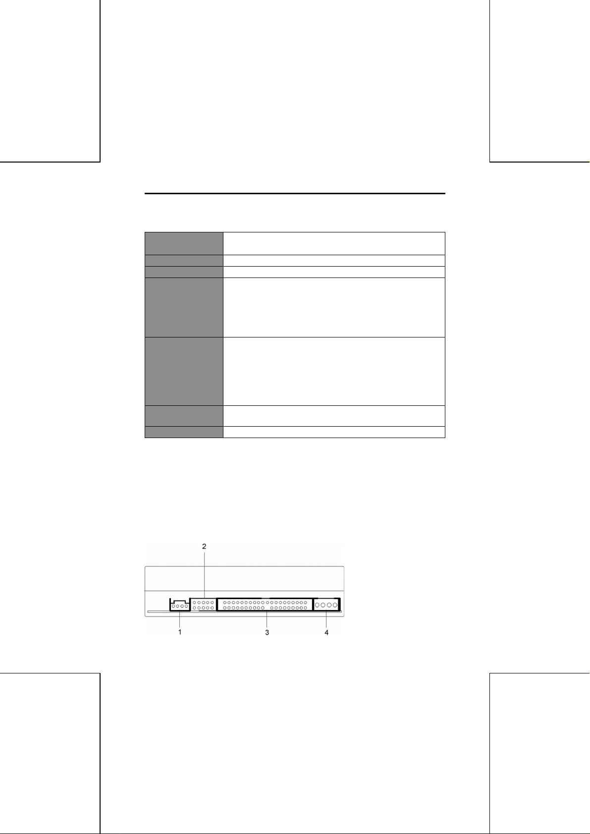
3. Plug connectors to the sockets on the rear side of DVD-ROM drive.
e
1. Audio Connector
2. Configuration Jumper
3. IDE Connector
4. Power Connector
3
Page 3

The Configuration jumper is for selection of the drive use mode and supporting PC.
Pin
Name
Function
1MAON
The drive is used in master mode.
2SLON
The drive is used in slave mode.
3CSON
Mode for drive setting by CSEL of the IDE interface.
4
Reserved.
ON
Stay in RPC Phase I mode.
Short-circuit socket is attached for the setting. (attached -> on; not attached -> off)
RPC
5
SET
NOTE: For a DVD Video playback system (computer) for Phase I, please use with
Phase I. When the DVD Video playback system (computer) and the drive
have different region codes. DVD Video playback is not possible. Set the
jumper switch to OFF only when use of a drive corresponding to Phase II has
been specified clearly for the DVD Video playback system (computer). This
drive will be initialized automatically and will operate in Phase II mode.
NOTE: Normall y, the red edge of the IDE cable corresponds to pin 1 of the IDE
interface on the DVD-ROM drive.
NOTE: The DVD-ROM drive supports Ultra DMA/33 mode to improve IDE data
transfer rate. To implement this function, you also need to make sure your
motherboard supports UDMA mode and the bus master IDE driver has been
installed properly.
Start RPC Phase II mode (Never return to Phase I mode
OFF
after Phase II mode is used.)
UUssiinnggtthheeDDVVDD--RROOMMDDrriivve
In most cases, software applications that utilize DVD-ROM drives control the DVDROM drive operations directly. However, you can control the drive manually using the
front-panel controls.
1. Headphone Jack
2. Volume Control
3. Power-on/Busy LED
4. Load/Eject Button
5. Disc Tray
e
4
 Loading...