

Page 1

Chapter 1
Overview
The AX53 is a high-performance Pentium-based system board that utilizes
the PCI/ISA architecture. It has four single in-line memory module (SIMM)
sockets that allow memory expansion up to a maximum of 512 MB. It also
comes either with 256-KB or 512-KB pipelined-burst cache.
To further enhance system performance, the board also integrates the Intel
430HX PCIset, a super I/O controller and a PCI mode 4 enhanced IDE
controller with bus master support.
One main feature of AX53 is the green power-management function that
extends energy conservation from system components to display monitor. It
complies with the power-saving standards of the U.S. Environmental
Protection Agency (EPA) Energy Star program.
The AX53 board measures 284 mm x 208 mm (11.2 in. x 8.2 in., mini-ATX
form).
1-1
Page 2
Overview
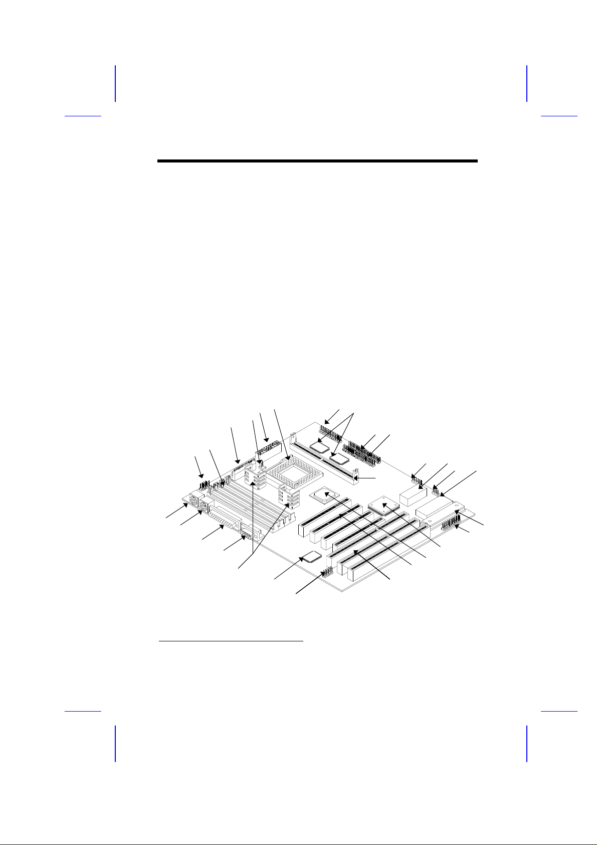
1.1 Board Layout
1 COM1 port connector 16 Keyboard controller
2 72-pin SIMM sockets 17 Multifunction connector
3 PS/2 power connector 18 Intel 82371SB ASIC
4 Two-pin fan connector 19 Intel 82439HX ASIC
5 ATX power connector 20 PCI slots
6 CPU socket 21 ISA slots
7 Floppy drive connector 22 Universal Serial Bus (USB)
8 Pipelined-burst cache connector
9 IDE1 connector 23 Super I/O controller
10 IDE2 connector 24 Voltage regulators with heatsink
11 COAST1 cache upgrade socket 25 COM2 port
12 IR connector 26 Parallel port
13 Real-time clock (RTC) 27 PS/2-mouse port
14 HDD LED connector 28 PS/2-keyboard port
15 System BIOS
6
1
2
5
4
3
7
8
9 10
12 13
11
14
15
28
27
26
25
24
1
Cache module type
1-2
23
22
21
20
19
18
17
16
Page 3

1.2 Specifications
Overview
Microprocessor
Memory
SIMM Sockets
ASICs
Bus Architecture
Expansion Slots
Connectors
Secondary Cache
BIOS
RTC & Battery
Board Size
Intel Pentium Processor
P54C
75/90/100/120/133/150/166/200 MHz
P55C
150/166/200 MHz
Cyrix 6x86 series
P120+, P133+, P150+
AMD K5 series
PR75, PR90, PR100
512 MB (maximum)
72-pin SIMM x 4
Intel 430HX PCIset
ISA, PCI
Three ISA and four PCI slots
One parallel connector (SPP/ECP/EPP)
Two serial connectors (UART 16C550)
Two dual-channel PCI mode 4 IDE connectors
(bus master transfer support)
One USB connector that supports two ports
One floppy disk drive connector
(360 KB/720 KB, 1.2 MB/1.44 MB/2.88 MB)
256-KB pipelined-burst cache, upgradable to
a maximum of 512-KB via cache upgrade
socket
AMI Plug-and-Play Flash ROM BIOS
Dallas DS12887A
284 mm x 108 mm (11.2 in. x 8.2 in.)
1-3
Page 4

Overview
1.3 System Board Parts
1.3.1 Microprocessor
The AX53 system board supports Intel Pentium, AMD K5 and Cyrix 6x86
processors. Chapter 2 tells how to install and upgrade the processor.
1.3.2 ASICs
The application-specific integrated circuits (ASICs) are the Intel 82439HX and
Intel 82371SB that belong to the Intel 430HX PCIset. This chipset allows the
system to support a higher memory (512 MB) and a pipelined-burst cache. It
also offers an error checking and correction (ECC) feature that enables the
system to detect, as well as correct the DRAM errors.
The Intel 82439HX that comes in a unique ball-grid array (BGA) packaging,
acts as the memory controller data path and the DRAM data bus buffer. The
BGA packaging offers better stability than the regular quad-flat packaging
(QFP).
The Intel 82371SB operates as the PCI/ISA bridge and IDE controller.
1.3.3 BIOS
The board supports the AMI basic input-output system (BIOS). The BIOS is a
program that performs the power-on self test (POST) upon booting. During
POST, this program activates the peripheral devices, tests onboard memory
and prepares the system for operation. For more information on AMI BIOS,
see Chapter 3.
1.3.4 Expansion Slots
The board has two ISA, three PCI and one PCI-/ISA-shared slots. The ISA
expansion slots are the black parallel bars on the system board. The PCI slots
are those with white color and are shorter than the ISA slots. There are rows
of golden pins inside each slot that serve as a clutch to secure the contacts of
the expansion board. For information on how to install the expansion boards,
see Chapter 2.
1-4
Page 5

Overview
1.3.5 DRAM Sockets
The system board has four 72-pin SIMM sockets that allow you to expand
system memory to a maximum of 512 MB. These sockets accept both singledensity and double-density SIMMs. Chapter 2 tells how to install memory
modules and the different memory configurations available.
1.3.6 Second-level Cache
The AX53 motherboard may come with 256-KB or 512-KB pipelined-burst
second-level cache. The board with 256-KB second-level cache also comes
with a COAST cache upgrade socket. The cache upgrade socket enables you
to upgrade cache to 512 KB.
The pipelined-burst cache improves system performance by shortening the
DRAM read prefetch time resulting to a faster data transfer rate.
1.3.7 Dual-channel PCI Mode 4 Enhanced IDE
Connectors
The AX53 board integrates two dual-channel PCI mode 4 enhanced integrated
drive electronics (E-IDE) connectors that allow the system to support four
E-IDE devices (including hard disks with more than 528-MB capacity). This
feature offers users increased data storage capacity.
1.3.8 Super I/O Controller
The onboard super I/O controller accommodates the following:
• Two UART 16450/16550-compatible fast serial ports
• A parallel port with standard parallel port (SPP), enhanced parallel port
(EPP) or extended capabilities port (ECP) support. Both the EPP and
ECP comply with the IEEE 1284 standards.
• 3.5-inch floppy disk drives with 720-KB, 1.44-MB or 2.88-MB format.
• 5.25-inch floppy disk drives with 360-KB, 1.2-MB format
1-5
Page 6

Overview
1.3.9 USB Connector
The onboard Universal Serial Bus (USB) connector enables AX53 to support
additional peripheral devices. See Chapter 2 for more details.
1.3.10 Keyboard Port
The keyboard port allows you to connect any PS/2-compatible keyboard. See
the board layout figure for the location of the keyboard port. Chapter 2 tells
how to connect a PS/2 keyboard.
1.3.11 Mouse Port
The board supports a PS/2 mouse port. See Chapter 2 for details on how to
connect a PS/2 mouse.
1-6
 Loading...