

Page 1

AAXX44SSPPEE MMaaxx OOnnlliinnee
AX4SPE Max
DOC. NO.: AX4SPEMAX-OL-E0306B
1
MMaannuuaall
Overview
Installation
Hardware
Drivers &
Utilities
BIOS Setup
AWARD
Glossary
Troubleshooting &
Technical Support
Page 2

AAXX44SSPPEE MMaaxx OOn
nlliinnee MMaannuuaall
WWhhaatt’’ss iinn tthhiiss mmaannuuaall
TUAX4SPE MaxUT.............................................................................................................................................1
TUWhat’s in this manualUT .................................................................................................................................................................... 2
TUYou Must NoticeUT ............................................................................................................................................................................ 9
TUBefore You StartUT .......................................................................................................................................................................... 10
TUOverviewUT ......................................................................................................................................................................................11
TUFeature HighlightUT ......................................................................................................................................................................... 12
TUQuick Installation ProcedureUT ....................................................................................................................................................... 17
TUMotherboard MapUT ........................................................................................................................................................................ 18
TUBlock DiagramUT ............................................................................................................................................................................. 19
TUHardware InstallationUT ............................................................................................................................20
TUAbout “User Upgrade Optional” and “Manufacture Upgrade Optional”…UT ................................................................................... 21
TUJP14 Clear CMOS DataUT .............................................................................................................................................................. 22
TUCPU InstallationUT...........................................................................................................................................................................23
TUCPU Fan InstallationUT ...................................................................................................................................................................25
TUCPU Jumper-less DesignUT ............................................................................................................................................................ 26
TUCPU Over-current ProtectionUT ......................................................................................................................................................27
TUBattery-less and Long Life DesignUT ..............................................................................................................................................28
TUAOpen “Watch Dog ABS”UT............................................................................................................................................................ 29
2
Page 3

AAXX44SSPPEE MMaaxx OOn
TUFull-range Adjustable CPU Core VoltageUT ....................................................................................................................................30
TUCPU and System Fan Connector (with H/W Monitoring)UT ............................................................................................................ 32
TUJP28 Keyboard/Mouse Wake-up JumperUT....................................................................................................................................33
TUDIMM SocketsUT ............................................................................................................................................................................. 34
TUATX Power ConnectorUT.................................................................................................................................................................36
TUAC Power Auto RecoveryUT............................................................................................................................................................36
TUIDE and Floppy ConnectorUT .......................................................................................................................................................... 37
TUSerial ATA SupportedUT ..................................................................................................................................................................39
TUConnecting Serial ATA DiskUT......................................................................................................................................................... 40
TUSupport RAID 0 and RAID 1UT........................................................................................................................................................43
TUFront Panel ConnectorUT ................................................................................................................................................................ 44
TUAGP (Accelerated Graphic Port) 8X Expansion SlotUT................................................................................................................... 45
TUAGP Protection Technology and AGP LEDUT .................................................................................................................................46
TUWOL (Wake on LAN)UT...................................................................................................................................................................47
TUIrDA ConnectorUT............................................................................................................................................................................49
TUSupport 10/100/1000 Mbps LAN onboardUT................................................................................................................................... 50
TUSupport USB 2.0 PortsUT ................................................................................................................................................................ 51
TUIEEE 1394 ConnectorsUT................................................................................................................................................................ 52
TUGame Port Bracket SupportedUT .................................................................................................................................................... 53
nlliinnee MMaannuuaall
3
Page 4

AAXX44SSPPEE MMaaxx OOn
TUColor Coded Back PanelUT ............................................................................................................................................................. 54
TUS/PDIF (Sony/Philips Digital Interface) ConnectorUT ...................................................................................................................... 55
TUSuper 5.1 Channel Audio EffectUT .................................................................................................................................................. 56
TUFront Audio ConnectorUT ................................................................................................................................................................57
TUDie-Hard BIOSUT ............................................................................................................................................................................58
TUJP15/JP16 Dr. Voice Language Select JumpersUT.........................................................................................................................60
TUJP2 Speaker Output JumperUT ....................................................................................................................................................... 61
TUCD Audio ConnectorUT ................................................................................................................................................................... 62
TUAUX-IN ConnectorUT.......................................................................................................................................................................63
TUCase Open ConnectorUT.................................................................................................................................................................64
TUSTBY LED (Standby LED)UT...........................................................................................................................................................65
TUResetable FuseUT ........................................................................................................................................................................... 66
TUEnlarged Aluminum HeatsinkUT ...................................................................................................................................................... 67
TULow ESR CapacitorUT ..................................................................................................................................................................... 68
TUThe noise is gone!! ---- SilentTekUT ................................................................................................................................................ 70
TUEzClockUT .......................................................................................................................................................................................73
TUHyper Threading T echnologyUT ......................................................................................................................................................77
TUAOConfig UtilityUT ........................................................................................................................................................................... 79
TURAID IntroductionUT ..................................................................................................................................81
nlliinnee MMaannuuaall
4
Page 5

AAXX44SSPPEE MMaaxx OOn
TUWhat’s RAID?UT.............................................................................................................................................................................. 81
TUWhat are the RAID levels?UT .......................................................................................................................................................... 82
TUHDD Capacity of RAID LevelsUT.....................................................................................................................................................85
TUSerial ATA RAID for Intel ICH5RUT..................................................................................................................................................86
TUSerial ATA RAID for Silicon Image 3112AUT ...................................................................................................................................88
TUPhoenix-AWARD BIOSUT ............................................................................................................................93
TUHow To Use Phoenix-Award™ BIOS Setup ProgramUT ................................................................................................................. 94
TUHow To Enter BIOS SetupUT........................................................................................................................................................... 95
TUWinBIOS UtilityUT............................................................................................................................................................................ 96
TUBIOS Upgrade under Windows environmentUT ..............................................................................................................................98
TUVivid BIOS technologyUT...............................................................................................................................................................100
TUDriver and UtilityUT ..................................................................................................................................101
TUAuto-run Menu from Bonus CDUT ................................................................................................................................................. 101
®
TUInstalling IntelUPU
TUInstalling Onboard Sound DriverUT ............................................................................................................................................... 103
TUInstalling Intel Application Accelerator RAID Edition Driver in Windows 2000/XPUT .............................................................................104
TUInstalling LAN DriverUT..................................................................................................................................................................105
TUInstalling USB 2.0 DriverUT ............................................................................................................................................................112
TUInstalling Silicon Image SiI3112A SATA Raid DriverUT...................................................................................................................117
UPU
Chipset Software Installation UtilityUT .................................................................................................................. 102
nlliinnee MMaannuuaall
5
Page 6

AAXX44SSPPEE MMaaxx OOn
TUGlossaryUT ...............................................................................................................................................124
TUAC97 CODECUT ...........................................................................................................................................................................124
TUACPI (Advanced Configuration & Power Interface)UT .................................................................................................................. 124
TUACR (Advanced Communication Riser)UT .................................................................................................................................... 124
TUAGP (Accelerated Graphic Port)UT ............................................................................................................................................... 125
TUAMR (Audio/Modem Riser)UT .......................................................................................................................................................125
TUATA (AT Attachment)UT ................................................................................................................................................................. 125
TUBIOS (Basic Input/Output System)UT............................................................................................................................................ 126
TUBluetoothUT ................................................................................................................................................................................... 126
TUCNR (Communication and Networking Riser)UT........................................................................................................................... 127
TUDDR (Double Data Rate) RAMUT.................................................................................................................................................. 127
TUECC (Error Checking and Correction)UT....................................................................................................................................... 127
TUEEPROM (Electronic Erasable Programmable ROM)UT .............................................................................................................. 127
TUEPROM (Erasable Programmable ROM)UT..................................................................................................................................128
TUEV6 BusUT ....................................................................................................................................................................................128
TUFCC DoC (Declaration of Conformity)UT .......................................................................................................................................128
TUFC-PGA (Flip Chip-Pin Grid Array)UT............................................................................................................................................128
TUFC-PGA2 (Flip Chip-Pin Grid Array)UT ......................................................................................................................................... 128
TUFlash ROMUT ................................................................................................................................................................................ 129
nlliinnee MMaannuuaall
6
Page 7

AAXX44SSPPEE MMaaxx OOn
TUHyper ThreadingUT........................................................................................................................................................................ 129
TUIEEE 1394UT ................................................................................................................................................................................. 129
TUParity BitUT .................................................................................................................................................................................... 130
TUPCI (Peripheral Component Interface) BusUT............................................................................................................................... 130
TUPDF FormatUT............................................................................................................................................................................... 130
TUPnP (Plug and Play)UT .................................................................................................................................................................. 130
TUPOST (Power-On Self Test)UT ......................................................................................................................................................131
TUPSB (Processor System Bus) ClockUT .........................................................................................................................................131
TURDRAM (Rambus Dynamic Random Access Memory)UT ............................................................................................................ 131
TURIMM (Rambus Inline Memory Module)UT....................................................................................................................................131
TUSDRAM (Synchronous DRAM)UT .................................................................................................................................................131
TUSATA (Serial ATA)UT......................................................................................................................................................................132
TUSMBus (System Management Bus)UT ..........................................................................................................................................132
TUSPD (Serial Presence Detect)UT................................................................................................................................................... 132
TUUSB 2.0 (Universal Serial Bus)UT .................................................................................................................................................132
TUVCM (Virtual Channel Memory)UT ................................................................................................................................................133
TUWireless LAN – 802.11bUT ............................................................................................................................................................ 133
TUZIP fileUT .......................................................................................................................................................................................133
TUTroubleshootingUT ...................................................................................................................................134
nlliinnee MMaannuuaall
7
Page 8

AAXX44SSPPEE MMaaxx OOn
TUTechnical SupportUT ................................................................................................................................138
TUProduct RegistrationUT............................................................................................................................142
TUHow to Contact UsUT...............................................................................................................................143
nlliinnee MMaannuuaall
8
Page 9

AAXX44SSPPEE MMaaxx OOn
nlliinnee MMaannuuaall
YYoouu MMuusstt NNoottiiccee
Adobe, the Adobe logo, Acrobat is trademarks of Adobe Systems Incorporated.
AMD, the AMD logo, Athlon and Duron are trademarks of Advanced Micro Devices, Inc.
Intel, the Intel logo, Intel Celeron, Pentium II, Pentium III and Pentium 4 are trademarks of Intel Corporation.
Microsoft, Windows, and Windows logo are either registered trademarks or trademarks of Microsoft Corporation in the United States and/or
other countries.
All product and brand names used on this manual are used for identification purposes only and may be the registered trade marks of their
respective owners.
All of the specifications and information contained in this manual are subject to change without notice. AOpen reserves the right to revise
this publication and to make reasonable changes. AOpen assumes no responsibility for any errors or inaccuracies that may appear in this
manual, including the products and software described in it.
This documentation is protected by copyright law. All rights are reserved.
No part of this document may be used or reproduced in a ny form or by any means, or stored in a database or retrieval system
without prior written permission from AOpen Corporation.
Copyright
©
P
P
1996-2003, AOpen Inc. All Rights Reserved.
9
Page 10

AAXX44SSPPEE MMaaxx OOn
nlliinnee MMaannuuaall
BBeeffoorree YYoouu SSttaarrtt
This Online Manual will introduce to the user how this product is installed. All useful information will be described in later chapters. Please
keep this manual carefully for future upgrades or system configuration changes. This Online Manual is saved in
recommend using Adobe Acrobat Reader 5.0 for online viewing, it is included in
siteUTH.
Although this Online Manual is optimized for screen viewing, it is still capable for hardcopy printing, you can print it by A4 paper size and set
2 pages per A4 sheet on your printer. To do so, choose File > Page Setup and follow the instruction of your printer driver.
Thanks for the help of saving our earth.
HTUPDF formatUTH, we
HBonus CDH or you can get free download from HTUAdobe web
10
Page 11

AAXX44SSPPEE MMaaxx OOn
nlliinnee MMaannuuaall
OOvveerrvviieeww
Thank you for choosing AOpen AX4SPE Max motherboard. AX4SPE Max is IntelP
factor featuring the
Socket 478 Pentium
which brings additional intelligence to systems. In the
spilt-transaction long burst transfer up to 2112MB/sec. According to different customer’s requirements, this motherboard supports
HTUDDR333UTH and HTUDDR400UTH RAM up to 4GB maximum. The onboard IDE controller supports HTUUltra DMA 33/66/100UTH mode, HTUSerial ATAUTH 150 MB/s
®
P
Socket 478 motherboard (M/B) based on the ATX form
HTUIntel Springdale-PE chipsetsUTH. As high performance chipset built in the M/B, AX4SPE Max motherboard supports IntelP
®
P
P
4 1.6GHz~3.06GHz. It supports 400/533/800MHz Front Side Bus (HTUFSBUTH) clock and HTUHyper-ThreadingUTH Technology
HTUAGP UTHperformance, it has one AGP slot to support AGP 8X/4X mode and pipelined
HTUDDR266UTH,
and IDE Raid 0, Raid 1 mode. There are 6 PCI slots provided
on this board and two
UTH ports on the back panel and one connector on the board
2.0
HTUIEEE1394 UTHconnectors. A total of 6 HTUUSB
give you the best use of all USB devices with the fancy speed
up to 480Mbps. More than that, on the strength of integrated
Broadcom LAN controller on board, which is a highly integrated
platform LAN connect devices, it provides 10/100/1000M bps
Ethernet for office and home use. Besides, AX4SPE Max has
S/PDIF connector and an
HTUAC97 CODEC RealTek ALC650UHT
chipset onboard, providing high performance and magic
surround stereo sound to let people enjoy working with it. Now,
let’s enjoy all features from AOpen AX4SPE Max motherboard.
®
P
11
Page 12

AAXX44SSPPEE MMaaxx OOn
nlliinnee MMaannuuaall
FFeeaattuurree HHiigghhlliigghhtt
CPU
Supports IntelP
478 technology.
®
P
Socket 478 PentiumP
®
P
4 (Northwood) 1.6GHz~3.06GHz+ with 400/533/800MHz Front Side Bus (FSB) designed for Socket
Chipset
Springdale-PE is a Memory Controller Hub (MCH) designed for use with the Pentium 4 processor with 512-KB L2 cache on 0.13 micron
processor. It provides CPU, DDR, AGP, Hub and CSA Interfaces. The CPU interface supports Pentium 4 processor subset of the Extended
Mode of the Scalable Bus Protocol. The MCH memory interface supports one up to two channels of DDR, and the AGP interface supports
0.8/1.5V signaling with 8X/4X data transfers and 8X/4X AGP Fast Writes. The Springdale-PE platform supports the fifth generation I/O
Controller Hub (ICH5R).
The ICH5R integrates an Ultra ATA 100 controller, two Serial ATA host controllers, one EHCI host controller and four UHCI host controllers
supporting eight external USB 2.0 ports, LPC interface controller; flash BIOS interface controller, PCI interface controller, AC’97 digital
controller, integrated LAN controller, integrated 1394 controller, an ASF controller and a hub interface for communication with the
Springdale-PE MCH.
Memory
With Springdale-PE chipset, this motherboard can support dual channel HTUDouble-Data-Rate (DDR) RAMUTH. The dual channel mode allows
chipsets to get data in 128 bit and zero wait state bursting between the RAM. The data transfer at 266/333/400MHz. The four slots of DDR
RAM can be composed of an arbitrary mixture of 64, 128, 256, 512 MB or 1GB DDR RAM and maximum up to 4GB.
12
Page 13

AAXX44SSPPEE MMaaxx OOn
nlliinnee MMaannuuaall
Expansion Slots
Including six 32-bit/33MHz PCI and one AGP 8X/4X slots. The HTUPCIUTH local bus throughput can be up to 132MB/s. Of six PCI slots provided,
all of them are master PCI slots with arbitration and decoding for all integrated functions and LPC bus. AX4SPE Max motherboard includes
one AGP expansion slot for a bus mastering AGP graphic card. The
video display sophistication and speed. The AGP video cards support data transfer rate up to 2112MB/s.
HTUAccelerated Graphics Port (AGP)UTH specification provides a new level of
AGP Protection Technology
With AGP Protection Technology implemented, this motherboard will automatically detect the voltage of AGP card and prevent your
chipsets from being burnt out.
Hyper-Threading Technology
Support Hyper-Threading Technology which brings additional intelligence to systems so that multiple tasks received from the processor can
be managed and prioritized more effectively.
Watch Dog ABS
Includes AOpen “Watch Dog ABS” function that can auto-reset system in 4.8 seconds when you fail the system overclocking.
13
Page 14

AAXX44SSPPEE MMaaxx OOn
nlliinnee MMaannuuaall
1MHz Stepping CPU Frequency Adjustment
Provides “1MHz Stepping CPU Frequency Adjustment” function in the BIOS. This magic function allows you to adjust CPU FSB frequency
from 100~400MHz by 1MHz stepping adjustment, and helps your system get maximum performance.
LAN Port
On the strength of Broadcom BCM5705, a fourth-generation triple-speed 10/100/1000 base-T Ethernet LAN Controller solution for
high-performance network applications, this motherboard provides 10/100/1000M bps Ethernet for office and home use.
Ultra DMA 33/66/100 Bus Mater IDE
Comes with an on-board PCI Bus Master IDE controller with two connectors that support four IDE devices in two channels, supports Ultra
DMA 33/66/100, PIO Modes 3 and 4 and Bus Master IDE DMA Mode 5, and supports Enhanced IDE devices.
Serial A TA
Integrated in ICH5R that contains independent DMA operation on two ports, the SATA controllers are completely software transparent with
the IDE interface, while providing a lower pin count and higher performance. The IC H5R SATA interface supports data transfer rates up to
150MB/s and RAID 0 and RAID 1. On the strength of the Silicon Image SATA controller, this motherboard provides two other SATA ports
(port 3 and port 4). This two ports support RAID 0 and RAID 1.
14
Page 15

AAXX44SSPPEE MMaaxx OOn
nlliinnee MMaannuuaall
On-board AC’97 Sound
AX4SPE Max uses RealTek AC97 CODEC RealTek ALC650 sound chip. This on-board audio includes a complete audio recording and
playback system.
Eight USB 2.0 Ports
Provides six ports on the back panel and one USB 2.0 connector on the board, providing a total of eight USB 2.0 interface to connect
devices such as mouse, keyboard, modem, scanner, etc.
Dr. Voice II
The Dr. Voice II can identify what kind of problems had occurred in the operating system. It provides four kinds language versions.
S/PDIF Connector
S/PDIF (Sony/Philips Digital Interface) is the newest audio transfer file format, which provides impressive quality through optical fiber and
allows you to enjoy digital audio instead of analog audio.
Power Management/Plug and Play
Supports the power management function which confirms to the power-saving standards of the U.S. Environmental Protection Agency (EPA)
Energy Star program. It also offers
user-friendlier.
HTUPlug-and-PlayUTH, which helps save users from configuration problems, thus making the system much
15
Page 16

AAXX44SSPPEE MMaaxx OOn
nlliinnee MMaannuuaall
Hardware Monitoring Management
Supports CPU or system fans status, temperature and voltage monitoring and alert, through the on-board hardware monitor module.
SilentTek
Combines “Hardware-Status Monitoring”, “Overheat Warning” and “Fan Speed Control” with user-friendly interfaces to provide a perfect
balance among noises, system performance and stability.
Enhanced ACPI
®
Fully implement the HTUACPIUTH standard for WindowsP
STD (Suspend to Disk, S4) and S5 features.
P
98/ME/2000/XP series compatibility, and supports Soft-Off, STR (Suspend to RAM, S3),
16
Page 17

AAXX44SSPPEE MMaaxx OOn
nlliinnee MMaannuuaall
QQuuiicckk IInnssttaallllaattiioonn PPrroocceedduurree
This page gives you a quick procedure on how to install your system. Follow each step accordingly.
1. Installing HTUCPUUTH and HTUFanUTH
2. HTUInstalling System Memory (DIMMUTH)
3. HTUConnecting Front Panel CableUTH
4. HTUConnecting IDE and Floppy CableUTH
5. HTUConnecting ATX Power CableUTH
6. HTUConnecting Back Panel CableUTH
7. HTUPower-on and Load BIOS Setup DefaultUTH
8. HTUSetting CPU FrequencyUTH
9. Reboot
10. Installing Operating System (such as Windows XP)
11. HTUInstalling Driver and UtilityUTH
17
Page 18
AAXX44SSPPEE MMaaxx OOn
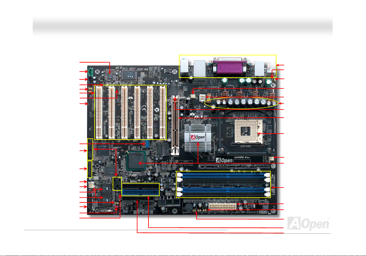
Motherboard Map
AC’97 CODEC
HTAUX-INTH Connector
CD-IN Connector
S/PDIF Connector
HT
Front Audio ConnectorTH
HT32-bit PCI Expansion Slot x6TH
IrDA Connector
Game Port Connector
USB 2.0 ConnectorTH
HT
SATA Port x 4
IEEE1394 Connector x 2
Wake on LAN Connector
SYSHTFAN3 ConnectorTH
JP24 BIOS Rescue Jumper
HT
Front Panel ConnectorTH
JP14 CMOS Clear JumperTH
HT
HTCase Open ConnectorTH
STBY LED
-
18
nlliinnee MMaannuuaall
HTColored Back PanelTH
Resetable FuseTH
HT
JP28 Keyboard/Mouse
Wakeup Jumper
HTFAN2TH Connector
SYS
HT
4-pin 12V. ATX Power ConnectorTH
HT
Low ESR CapacitorsTH
AGP Protection LED
HTAGP 8x Expansion SlotTH
HT478-pin CPU socket (Northwood)
with Voltage and Frequency
Auto-detection that supports Intel
®
P
Pentium
P
4 1.6~3.06GHz+ CPUTH
CPUFAN1 connector
Springdale-PE Chipset that
supports 400/533/800MHz
FSB,
H184-pin DIMMx4 support
DDR400/333/266 SDRAM
maximum up to 4GB
ATX Power ConnectorTH
HT
JP2 Speaker Output Connector
JP15/JP16 Dr. Voice II
Language Select Jumper
HT
ATA66/100 IDE Connector x2TH
FDD ConnectorTH
HT
®
P
P
H
Page 19
AAXX44SSPPEE MMaaxx OOn
nlliinnee MMaannuuaall
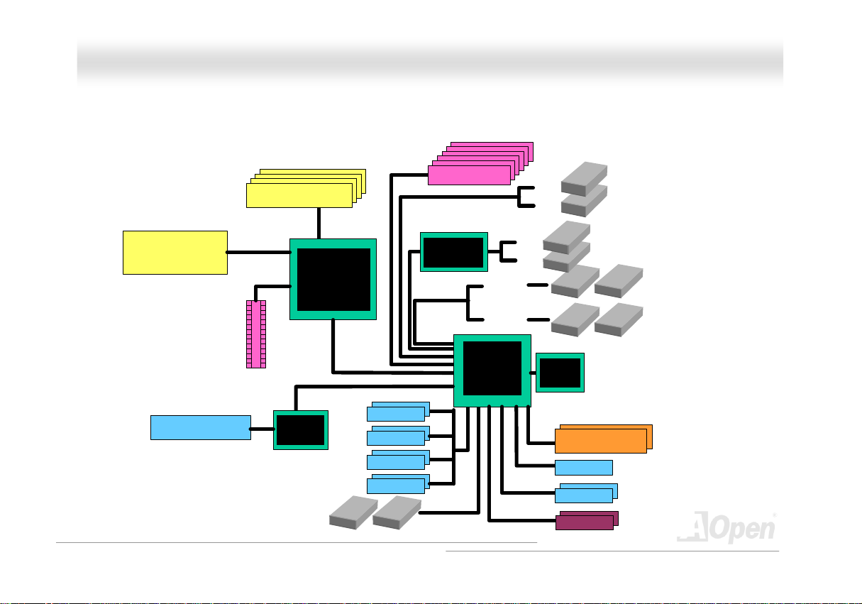
BBlloocckk DDiiaaggrraamm
Socket 478
Intel Pentiu m 4
CPU (Northwood)
AGP 8X Sl ot
LAN connect Component
533/800MHz
System Bus
AGP bus
Floppy Disk Drive x2
DDR400/333/266 Dual Channel
RAM Up to 4GB
DIMM Socket x4
Intel
Springdale-PE
Broadcom
BCM5705
USB Port x8
PCI Bus
USB Port
USB Port
USB Port
USB Port
32-bit PCI Slot x6
2 Serial AT A Por ts
150MB/s
Silicon Imag e
SATA Controller
ATA 66/100
Primary
Channel
Secondary
Channel
ICH5R
SATA 3
SATA 4
SATA 1
SATA 2
RealTek
AC97
CODEC
4Mbit Flash EEPROM
4Mbit Flash EEPROM
Parallel Port
Serial Port x2
IEEE1394 x2
IEEE1394 x2
IDE Drive x4
19
Page 20

AAXX44SSPPEE MMaaxx OOn
nlliinnee MMaannuuaall
HHaarrddwwaarree IInnssttaallllaattiioonn
This chapter describes jumpers, connectors and hardware devices of this motherboard.
Note: Electrostatic discharge (ESD) can damage your processor, disk drives, expansion boards, and other
components. Always observe the following precautions before you install a system component.
1. Do not remove a component from its protective packaging until you are ready to install it.
2. Wear a wrist ground strap and attach it to a metal part of the system unit before handling a component. If
a wrist strap is not available, maintain contact with the system unit throughout any procedure requiring
ESD protection.
20
Page 21

AAXX44SSPPEE MMaaxx OOn
nlliinnee MMaannuuaall
AAbboouutt ““UUsseerr UUppggrraaddee OOppttiioonnaall”” aanndd ““MMaannuuffaaccttuurree UUppggr
When you read this online manual and start to assemble your computer system, you may notice that some of the functions are marked as
“User Upgrade Optional” or “Manufacture Upgrade Optional”. Although all of AOpen’s motherboards have included many amazing and
powerful features, sometimes not every user is familiar with these powerful features. As a result of this we define features that can be
upgraded by users as “User Upgrade Optional”. You can upgrade these functions by purchasing additional devices. As for functions that
cannot be upgraded by users, we define them as “Manufacture Upgrade Optional”. If need be, you can contact our local distributors or
resellers to purchase “Manufacture Upgrade Optional” components, and again you are also welcome to visit our official website at
HTUenglish.aopen.com.twUTH for detail information.
raaddee OOppttiioonnaall””……
21
Page 22
(
AAXX44SSPPEE MMaaxx OOn
nlliinnee MMaannuuaall
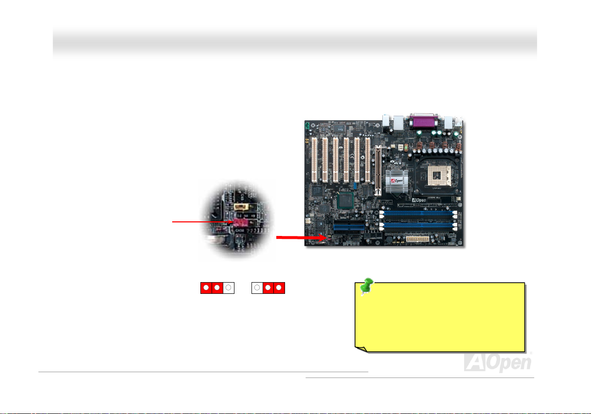
JJPP1144 CClleeaarr CCMMOOSS DDaattaa
You can clear CMOS to restore system default setting. To clear the CMOS, follow the procedure below.
1. Turn off the system and unplug the AC power.
2. Remove ATX power cable from connector PWR2.
3. Locate JP14 and short pins 2-3 for a few seconds.
4. Return JP14 to its normal setting by shorting pin1 & pin2.
5. Connect ATX power cable back to connector PWR2.
Pin 1
1
Normal
default)
1
Clear CMOS
Tip: When should I Clear CMOS?
1. Boot fails because of overclocking…
2. Forget password…
3. Troubleshooting…
22
Page 23
AAXX44SSPPEE MMaaxx OOn
nlliinnee MMaannuuaall
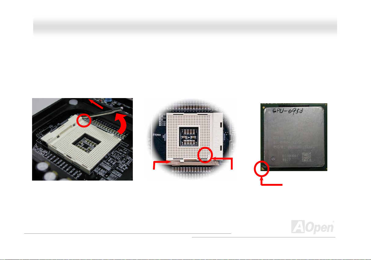
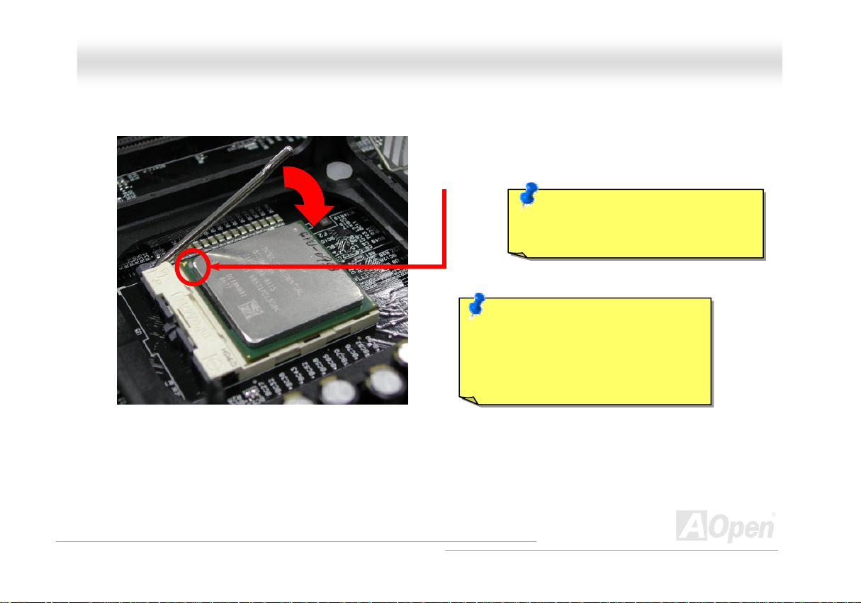
CCPPUU IInnssttaallllaattiioonn
This motherboard supports IntelP
socket.
1. Pull up the CPU socket lever and
up to 90-degree angle.
®
P
Pentium 4 Socket 478 series CPU (Willamette). Be careful of CPU orientation when you plug it into CPU
2. Locate Pin 1 in the socket and look for mark on the CPU upper interface.
Match Pin 1 and cut edge, then insert the CPU into the socket.
Note: Those pictures are for example only; they may not look the same with the motherboard you purchased.
CPU socket
Lever
CPU pin 1 and
cut edge
CPU cut edge
23
Page 24
y
AAXX44SSPPEE MMaaxx OOn
3. Press down the CPU socket lever and finish CPU
installation.
Note: This picture is for example only; it may not look the same with the motherboard you purchased.
CPU cut edge
Note: If you do not match the CPU
socket Pin 1 and CPU cut edge well, you
ma
damage the CPU.
Note: This socket supports
Micro-FC-PGA2 package CPU, which is
the latest CPU package developed by
Intel. Other forms of CPU package are
impossible to be fitted in.
nlliinnee MMaannuuaall
24
Page 25
AAXX44SSPPEE MMaaxx OOn
nlliinnee MMaannuuaall
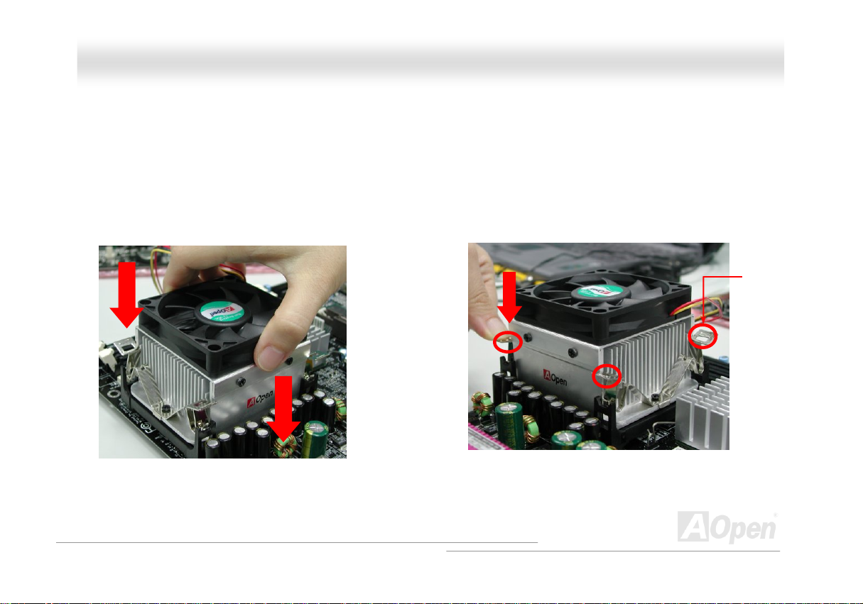
CCPPUU FFaann IInnssttaallllaattiioonn
This motherboard comes with a retention module attached on the CPU socket when shipped, we strongly recommend you to install AOpen
special designed CPU Fan as shown below on the retention module for better heat dissipation. Please install the CPU Fan correctly as the
following pictures shown.
1. Gently put the CPU Fan down on the
retention module with clips aligning correctly
to the four corners.
Note: The picture above may look different from the product you purchased.
2. Pressing down the four clips with force one by one
on the retention module.
Clip
25
Page 26
AAXX44SSPPEE MMaaxx OOn
nlliinnee MMaannuuaall
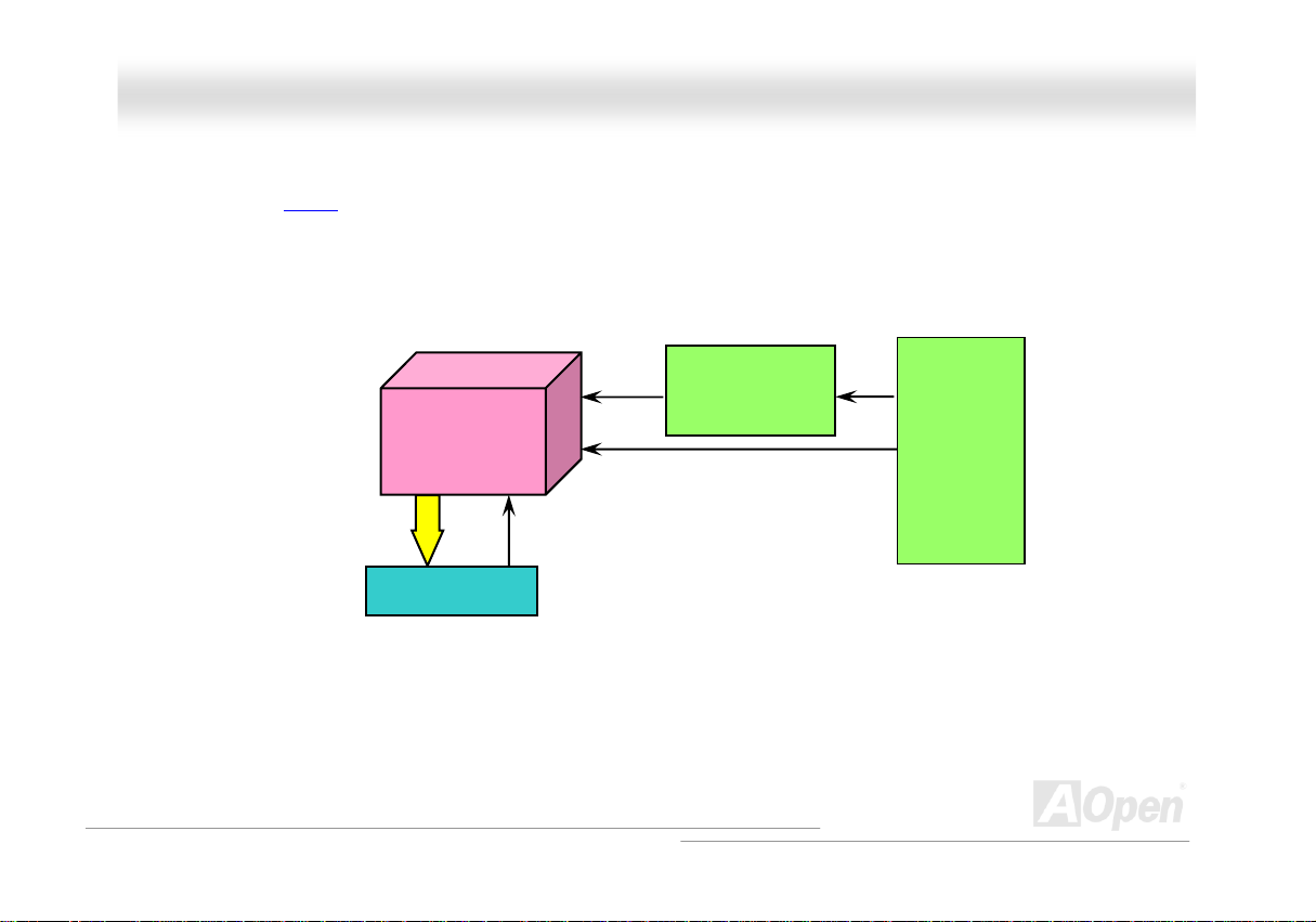
CCPPUU JJuummppeerr--lleessss DDeessiiggnn
CPU VID signal and HTUSMbusUTH clock generator provide CPU voltage auto-detection and allows the user to set the CPU frequency through the
BIOS setup, therefore no jumpers or switches are used. The disadvantages of the Pentium based jumper-less designs are eliminated.
There will be no worry of wrong CPU voltage detection.
CPU VID signal
(Automatically generates CPU voltage)
IntelP
Power Regulator
®
P
Socket 478
Pentium 4
CPU voltage
Clock Generator
CPU Freq. Ratio
BIOS
Controlled
Circuit
26
Page 27
AAXX44SSPPEE MMaaxx OOn
nlliinnee MMaannuuaall
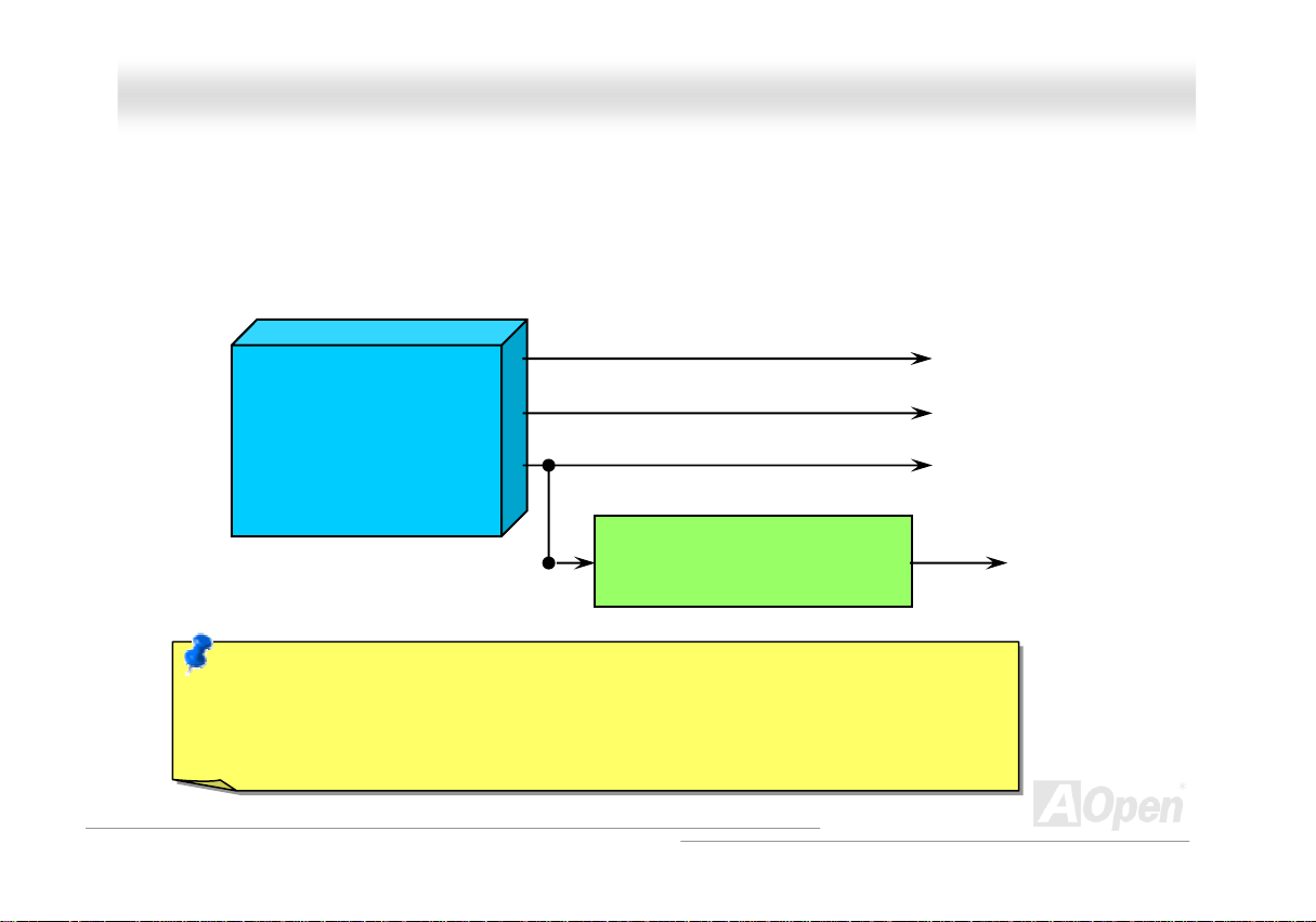
CCPPUU OOvveerr--ccuurrrreenntt PPrrootteeccttiioonn
The Over Current Protection is a popular implementation on ATX 3.3V/5V/12V switching power supply. However, the new generation CPU
uses different voltage with a regulator to transfer 12V to CPU voltage (for example, 2.0V), and thus makes 5V over current protection
useless. This motherboard is with switching regulator onboard supporting CPU over-current protection; in conjunction with 3.3V/5V/12V
power supply provide the full line over-current protection.
ATX Switching Power Supply
Note: Although we have implemented protection circuit try to prevent any human operating mistake,
there is still certain risk that CPU, memory, HDD, add-on cards installed on this motherboard may be
damaged because of component failure, human operating error or unknown nature reason. AOpen
cannot guaranty the protection circuit will always work perfectly.
12V (Protected by power supply)
3.3V (Protected by power supply)
5V (Protected by power supply)
Onboard Power Regulator
(Over-Current Protection)
CPU Core Voltage
27
Page 28
AAXX44SSPPEE MMaaxx OOn
nlliinnee MMaannuuaall
BBaatttteerryy--lleessss aanndd LLoonngg LLiiffee DDeessiiggnn
This Motherboard implements a HTUFlash ROMUTH and a special circuit that provide you no batter power consumption of current CPU and CMOS
Setup configurations. The RTC (real time clock) can also keep running as long as the power cord is plugged. If you lose your CMOS data
by accident, you can just reload the CMOS configurations from Flash ROM and the system will recover as usual.
ATX Stand-by Power
Battery
Flash ROM
(Real Time Clock)
Auto Switch
RTC
00:00:00
CMOS
Auto switch to ATX standby
power as long as AC power line
is plugged. This smart design
increases battery life if you still
plug battery on motherboard.
Backup by EEPROM
28
Page 29
AAXX44SSPPEE MMaaxx OOn
nlliinnee MMaannuuaall
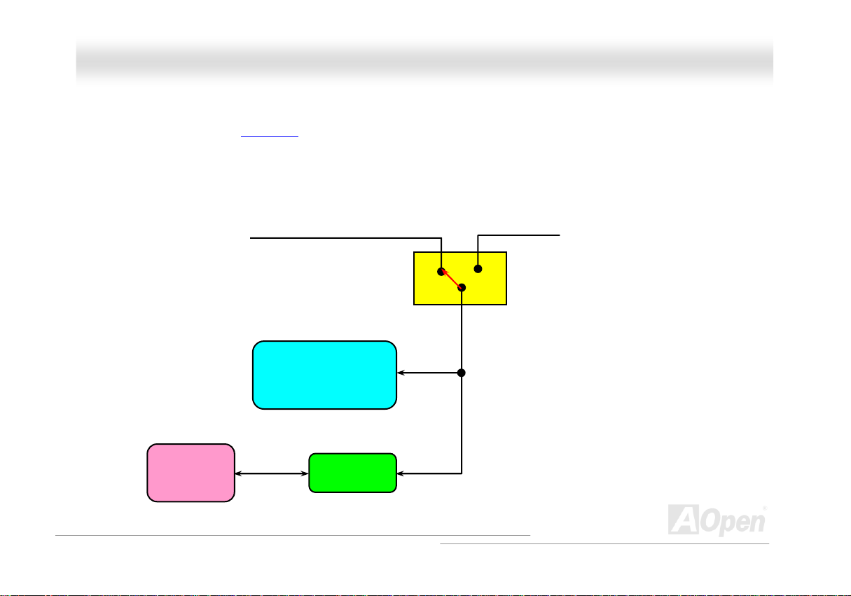
AAOOppeenn ““WWaattcchh DDoogg AABBSS””
user’s settings stored in the BIOS. If system failed in BIOS POST, the “Watch Dog Timer” will reset the system to reboot in five seconds.
Then, BIOS will detect the CPU’s default frequency and POST again. With this special feature, you can easily overclock your system to get
a higher system performance without removing the system housing and save the hassle from setting the jumper to clear CMOS data when
system hangs.
AOpen
Watch Dog ABS
Enable/Disable Signal from
AOpen provides a special and useful feature on this motherboard for overclockers. When you
power-on the system, the BIOS will check last system
enable “Watch Dog ABS” function immediately, and set the CPU FSB frequency according to
BIOS
BIOS
Reset Signal
Clock Generator
Countdown about
5 seconds if fails
in POST
CPU
HTUPOSTUTH status. If it succeeded, the BIOS will
CPU ID Signal
29
Page 30

AAXX44SSPPEE MMaaxx OOn
nlliinnee MMaannuuaall
FFuullll--rraannggee AAddjjuussttaabbllee CCPPUU CCoorree VVoollttaaggee
This function is dedicated to overclockers and supports Adjustable CPU Core Voltage from 1.10V to 2.025V. However, this motherboard can
also automatically detect CPU VID signal and generates proper CPU core voltage.
SSeettttiinngg CCPPUU FFrreeqquueennccyy
BIOS Setup > Frequency/Voltage Control > CPU Bus Frequency
This motherboard is CPU jumper-less design, you can set CPU frequency in BIOS; no jumpers or switches are needed. The default setting
is "table select mode". You can adjust the FSB from "CPU Host/RAM/PCI Clock" for overclocking.
Core Frequency = CPU FSB Clock * CPU Ratio
PCI Clock = CPU FSB Clock / Clock Ratio
AGP Clock = PCI Clock x 2
CPU Ratio 8x, 10x… 21x, 22x, 23x, 24x
CPU FSB (By BIOS table) 100-400MHz
30
Page 31

AAXX44SSPPEE MMaaxx OOn
nlliinnee MMaannuuaall
Northwood CPU
Pentium 4 1.6G 1600MHz 100MHz 400MHz 16x
Pentium 4 1.6G 1600MHz 133MHz 533MHz 12x
Pentium 4 1.7G 1700MHz 133MHz 533MHz 13x
Pentium 4 1.8G 1800MHz 100MHz 400MHz 18x
Pentium 4 2.0G 2000MHz 100MHz 400MHz 20x
Pentium 4 2.2G 2200MHz 100MHz 400MHz 22x
Pentium 4 2.2G 2200MHz 133MHz 533MHz 16x
Pentium 4 2.26G 2260MHz 133MHz 533MHz 17x
Pentium 4 2.4G 2400MHz 100MHz 400MHz 24x
Pentium 4 2.4G 2400MHz 133MHz 533MHz 18x
CPU Core
Frequency
FSB
Clock
System
Bus
Ratio
Note: Intel Springdale-PE chipset only
support Northwood processors, and don’t
support Willamette or Celeron processors.
Northwood processor would detect the
clock ratio automatically, you may not be
able to adjust the clock ratio in BIOS
manually.
Pentium 4 2.53G 2530MHz 133MHz 533MHz 19x
Pentium 4 2.6G 2600MHz 200MHz 800MHz 13x
Pentium 4 2.66G 2660MHz 133MHz 533MHz 20x
Pentium 4 2.8G 2800MHz 133MHz 533MHz 21x
Pentium 4 2.8G 2800MHz 200MHz 800MHz 14x
Pentium 4 3.06G 3000MHz 200MHz 800MHz 15x
Warning: Intel Springdale-PE chipset
supports maximum 800MHz (200MHz*4)
system bus and 66MHz AGP clock; higher
clock setting may cause serious system
damage.
31
Page 32

AAXX44SSPPEE MMaaxx OOn
nlliinnee MMaannuuaall
CCPPUU aanndd SSyysstteemm FFaann CCoonnnneeccttoorr ((wwiitthh HH//WW MMoonniittoorriinngg))
Plug in the CPU fan cable to the 3-pin CPUFAN1 connector. If you have chassis fan, you can also plug it on SYSFAN2 or SYSFAN3
connector.
SYSFAN2 Connector
CPUFAN1 Connector
GND
+12V
SENSOR
Note: Some CPU fans do not have
sensor pin, so that they cannot support
hardware monitoring function.
SYSFAN3 Connector
32
Page 33

AAXX44SSPPEE MMaaxx OOn
nlliinnee MMaannuuaall
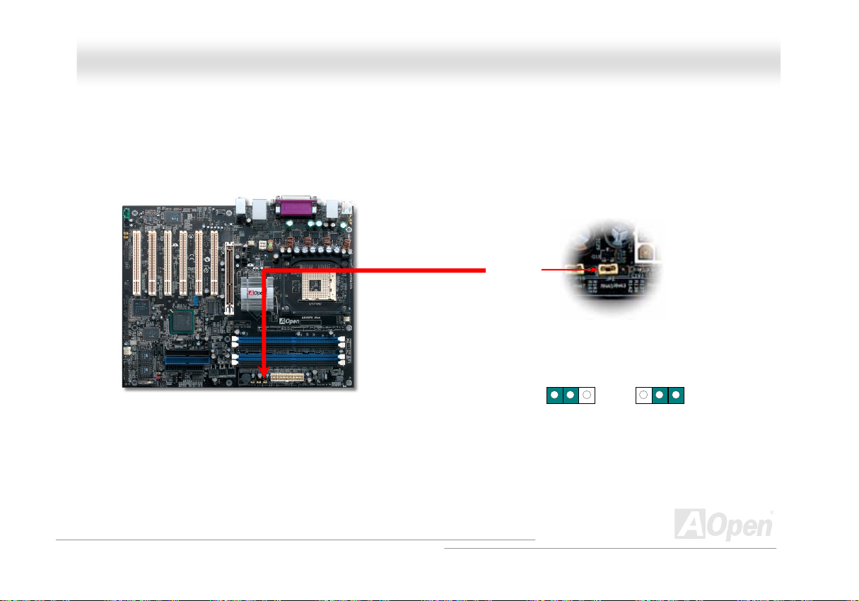
JJPP2288 KKeeyybbooaarrdd//MMoouussee WWaakkee--uupp JJuummppeerr
This motherboard provides PS2 keyboard / mouse wake-up function. You can use JP28 to enable or disable this function, which could
resume your system from suspend mode with keyboard or mouse. The factory default setting is set to “Disable” (1-2), and you may en able
this function by setting the jumper to 2-3.
Pin 1
1 1
Disable
(Default)
Enable
33
Page 34

AAXX44SSPPEE MMaaxx OOn
nlliinnee MMaannuuaall
DDIIMMMM SSoocckkeettss
This motherboard has four 184-pin DDR HTDIMMTH sockets that allow you to install 128-bit dual channel HTUDDR400UTH, HTUDDR333UTH or HTUDDR266UTH memory
up to 4GB. Only non-ECC DDR RAM is supported. Please install suitable modules; otherwise serious damage may occur on memory
sockets or you RAM modules. Please note that when you install DDR333 memory module and have y our CPU FSB set at 800MHz,
the memory can only run with the spe ed of DDR320. It is limitation of Intel. For other limitation of CPU types, please see the table
below.
Warning: This motherboard supports DDR RAM. Please do
not install the SDRAM on the DDR RAM sockets; otherwise it
will cause serious damage on memory sockets or SDRAM
module.
Item
CPU FSB 400MHz V X X
CPU FSB 533MHz V V X
CPU FSB 800MHz V
DDR266 DDR333 DDR400
⊙
Note: To run dual channel speed, you have to use
the same type memory modules installed on two
DIMMs. If you install two different sized modules,
the system can only run single channel mode and
with the speed of that lower memory module.
V
DIMMA1
DIMMA2
DIMMB1
DIMMB2
34
Page 35

’
AAXX44SSPPEE MMaaxx OOn
nlliinnee MMaannuuaall
HHooww ttoo IInnssttaallll MMeemmoorryy MMoodduulleess
Please follow the procedure as shown below to finish memory installation.
1. Make sure the DIMM module’s pin face down and match the socket’s size as depicted below.
2. Insert the module straight down to the DIMM slot with both hands and press down firmly until the DIMM module is securely in place.
3. Repeat step 2 to finish additional DIMM modules installation.
Note: These images are for example only; they may not be exactly the same as the motherboard you purchased.
Tab
Key
40 pins 52 pins
Note: Please pay attention to
the Blue slots. To run dual
channel speed, you should
insert the RAM in the slot of
DIMM A1 and DIMM B1 or
DIMM A2 and DIMM B2.
Please don't use the
different frequency DIMM on
dual channel
Note: The tabs of the DIMM slot
will close-up to hold the DIMM in
place when the DIMM touches the
s bottom.
slot
Pin 1
35
Page 36

AAXX44SSPPEE MMaaxx OOn
nlliinnee MMaannuuaall
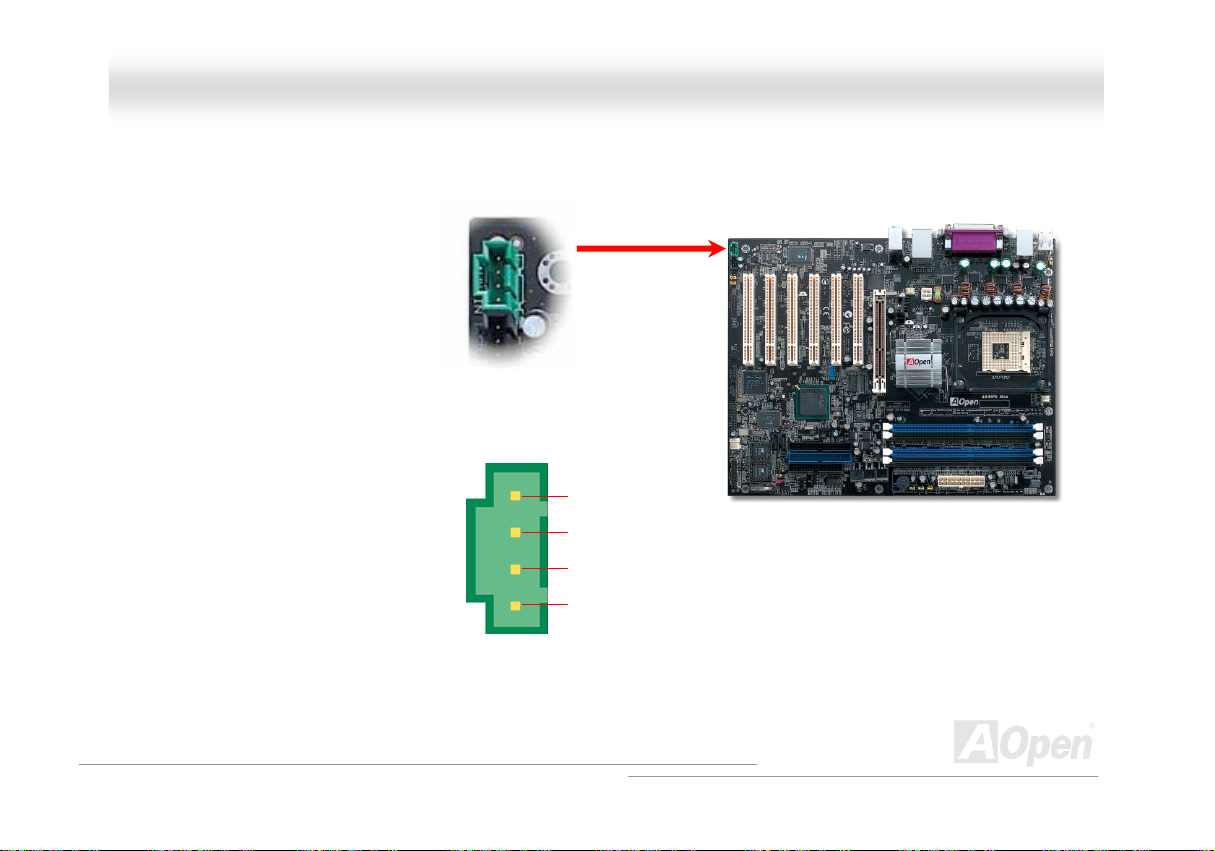
AATTXX PPoowweerr CCoonnnneeccttoorr
This motherboard comes with a 20-pin and 4-pin ATX power connector. Make sure you plug in the right direction. We strongly recommend
you to connect the 4-pin 12V ATX connector before connecting the 20-pin ATX power connector and use standard power supply specially
designed for Pentium 4 system.
AACC PPoowweerr AAuuttoo RReeccoovveerryy
A traditional ATX system should remain at power off stage when AC power resumes from power failure. This design is inconvenient for a
network server or workstation, without an UPS, that needs to keep power-on. This motherboard implements an AC Power Auto Rec overy
function to solve this problem.
36
Page 37

AAXX44SSPPEE MMaaxx OOn
nlliinnee MMaannuuaall
IIDDEE aanndd FFllooppppyy CCoonnnneeccttoorr
Connect 34-pin floppy cable and 40-pin IDE cable to floppy connector FDD and IDE connector. Be careful of the pin1 orientation. Wrong
orientation may cause system damage.
Secondary
Slave (4th)
Secondary
Master (3rd)
Pin 1
FDD Connector
Pin 1
Primary
Slave (2nd)
ATA 66/100 IDE
Connector
IDE 2 (Secondary)
IDE 1 (Primary)
Primary
Master (1st)
37
Page 38

AAXX44SSPPEE MMaaxx OOn
IDE1 is also known as the primary channel and IDE2 as the secondary channel. Each channel supports two IDE devices that make a total
of four devices. In order to work together, the two devices on each channel must be set differently to Master and Slave mode. Either one
can be the hard disk or the CDROM. The setting as master or slave mode depends on the jumper on your IDE device, so please refer to
your hard disk and CDROM manual accordingly.
Tip:
1. For better signal quality, it is recommended to set the far end side device to
master mode and follow the suggested sequence to install your new device.
Please refer to above diagram
2. To achieve the best performance of Ultra DMA 66/100 hard disks, a special
80-wires IDE cable for Ultra DMA 66/100 is required.
Warning: The specification of the IDE cable is a maximum of 46cm (18 inches);
make sure your cable does not exceed this length.
nlliinnee MMaannuuaall
38
Page 39

AAXX44SSPPEE MMaaxx OOn
nlliinnee MMaannuuaall
SSeerriiaall AATTAA SSuuppppoorrtteedd
The traditional parallel ATA specification has defined the standard storage interface for PCs with its original speed of just 3 Mbytes/second
since the protocol was introduced in the 1980s. And the latest generation of the interface, Ultra ATA-133, has been developed further with a
burst data transfer rate of 133 Mbytes/second. However, while ATA has enjoyed an illustrious track record, the specification is now showing
its age and imposes some serious design issues on today’s developers, including a 5-volt signaling requirement, high pin count, and
serious cabling headaches.
The Serial ATA specification is designed to overcome these design limitations while enabling the storage interface to scale with the growing
media rate demands of PC platforms. Serial ATA is to replace parallel ATA with the compatibility with existing operating systems and drivers,
adding performance headroom for years to come. It reduces voltage and pins count requirements and can be implemented with thin and
easy to route cables.
SATA port 1 (ICH5R)
SATA port 4 (Sil 3112)
Serial ATA Ports
SATA port 3 (Sil 3112)
SATA port 2 (ICH5R)
39
Page 40

AAXX44SSPPEE MMaaxx OOn
nlliinnee MMaannuuaall
CCoonnnneeccttiinngg SSeerriiaall AATTAA DDiisskk
To connect a Serial ATA disk, you have to have a 7-pin serial ATA cable. Connect two ends of the serial ATA cable to the serial ATA header
on the motherboard and the disk. Like every other traditional disk, you also have to connect a power cable. Please be noted that it is a
jumper free implement; you don’t need to set jumpers to define a master or slave disk. When serial ATA hard disks are installed on serial
ATA ports, the one connected on Port 0(SATA 1) will be set as the first boot device automatically. Please be noted that it doesn’t support
Hot-Plug in function.
Item Parallel ATA Serial A TA
Bandwidth 100/133 MB/Sec 150/300/600 MB/Sec
Volts 5V 250mV
Pins 40 7
Length Limitation 18 inch (45.72cm) 1 meter (100cm)
Cable Wide Thin
Ventilation Bad Good
Peer-to-Peer No Yes
Comparison between Parallel ATA and Serial ATA
40
Page 41

AAXX44SSPPEE MMaaxx OOn
nlliinnee MMaannuuaall
AAddjjuussttiinngg YYoouurr HHaarrdd DDiisskk
Except its original 2 sets of parallel IDE, this motherboard does come with the support for the latest Serial ATA hard disk. If you are unable
to find your newly installed Serial ATA hard disks on your operating system after you have had installed them on, the problem mainly lies in
the BIOS setting. You may simply adjust BIOS settings to have them work properly.
After having properly installed your hard disks, you may directly get into the BIOS setting screen for adjustment. You may simpl y press
“Integrated Peripherals Æ On-Chip IDE Device Æ On-Chip Serial ATA” to choose your preferable mode. If you have no intention of
changing its setting, the default would be Auto.
41
Page 42

AAXX44SSPPEE MMaaxx OOn
If you intend to change the default setting, simply press Enter for a list of selection:
1. Disabled: You may choose this item if you’re sure that only traditional IDE hard
disks had been installed on your system. Disabling this item may also cancel the
detection to Serial ATA hard disk during POST, which theoretically, could speed up
your boot-up timing for a little bit; however, please remember to re-adjust the
settings here if you intend to use Serial ATA hard disk later.
2. Auto: This is the default setting upon receipt of the motherboard. Basically, if your
system functions properly, it’s not necessary to change it. The system will
automatically recognize the first hard disk on IDE1 as the first boot device.
Note: Please be informed that when you are using Windows98/ME with six hard disks fully installed, Auto mode is not able to function
properly, it’s just because Windows98/Me is not able to energize Enhanced Mode to detect all hard disks.
3. Combined Mode: If you have had installed traditional IDE hard disks and Serial ATA hard disks at the same time, then you may
choose this Combined Mode. Under this mode, you may randomly choose either IDE hard disks or Serial ATA had disk as your first
boot device. But please be aware that Serial ATA will exist with IDE in a mapping way, which also means it will occupy one of the IDE
Channel and left you with one IDE Channel only.
4. Enhanced Mode: If you are using the latest operating system (say, Windows XP, Windows.NET Server), it is highly recommended to
select Enhanced Mode. The system would be able to detect all six devices (traditional IDE x4, Serial ATA x 2) completely and functions
perfectly under this mode. But please be noted that it is defaulted with using traditional IDE as the first boot device.
Note: From our practical lab tests, we found no obvious problem or mistakes happened under Windows2000 operating system, but,
however, it is not within the regulation recommended by Intel.
5. SATA Only: You may select this SATA Only mode if you have had installed Serial ATA hard disks only. It also allows you to select
booting sequence from Port0 (SerialATA1) or Port1 (SerialATA2).
nlliinnee MMaannuuaall
42
Page 43

AAXX44SSPPEE MMaaxx OOn
nlliinnee MMaannuuaall
SSuuppppoorrtt RRAAIIDD 00 aanndd RRAAIIDD 11
With Intel ICH5R chipset and Silicon Image Sil3112A onboard, this motherboard provides a cost-effective, high performance striping (RAID
0) and mirroring (RAID 1) solution. With striping, identical drives can read and write data in parallel to increase performance. Mirroring
increase read performance through load balancing and elevator seeking while creating a complete backup of your files. When supporting
RAID 0 or RAID 1, you should connect SATA hard driver disks to SATA Header 1and 2. You can set in BIOS which mode you want to
support.
43
Page 44

AAXX44SSPPEE MMaaxx OOn
nlliinnee MMaannuuaall
FFrroonntt PPaanneell CCoonnnneeccttoorr
Pin1
Attach the power LED, Keylock, speaker, power and reset switch connectors to the
corresponding pins. If you enable “Suspend Mode” item in BIOS Setup, the ACPI &
Power LED will keep flashing while the system is in suspend mode.
Locate the power switch cable from your ATX housing. It is 2-pin female connector
from the housing front panel. Plug this connector to the soft-power switch connector
marked SPWR.
Suspend Type ACPI LED
Power on Suspend (S1) or Suspend to RAM (S3) Flashing for every second
Suspend to Disk (S4) The LED will be turned off
1
NC
NC
+5V
+5V
+5V
GND
NC
5VSB
SPWR
ACPI LED GND
ACPILED
NC
ACPI_B
GND
RESET
GND
IDE LED
Speaker
1
SPWR
IDE LED
ACPI & PWR LED
ACPI LED (BLUE)
Reset
IDE LED
SPEAKER
44
Page 45

AAXX44SSPPEE MMaaxx OOn
nlliinnee MMaannuuaall
AAGGPP ((AAcccceelleerraatteedd GGrraapphhiicc PPoorrtt)) 88XX EExxppaannssiioonn SSlloott
AX4SPE Max provides an HTUAGPUTH 8x slot. The AGP 8X is a bus interface targeted for high-performance 3D graphic. AGP uses both rising and
falling edge of the 66MHz clock, for 4X AGP, the data transfer rate is 66MHz x 4bytes x 4 = 1056MB/s. AGP is now moving to AGP 8x mode,
which is 66MHz x 4bytes x 8 =2112MB/s. You can adjust AGP voltage in BIOS within a rage from 1.5V to 1.7V.
Warning: It is strongly
recommended not to adjust
voltage/clock of AGP/PCI
when connecting any SATA
service. It is because when
the voltage/clock for
AGP/PCI is adjusted, the
clock for SATA couldn’t
keep 100MHz, and the
45
Page 46
AAXX44SSPPEE MMaaxx OOn
nlliinnee MMaannuuaall
AAGGPP PPrrootteeccttiioonn TTeecchhnnoollooggyy aanndd AAGGPP LLEEDD
With the outstanding R&D ability of AOpen and its specially developed circuit, this motherboard implements a blend new technology to
protect your motherboard from being damaged by over-voltaging of AGP card. When AGP Protection Technology is implemented, this
motherboard will automatically detect the voltage of AGP card and prevent your chipsets from being burnt out. Please note that if you install
a AGP card with 3.3V, which is not supported by Intel Springdale-PE chipset, the AGP LED on the motherboard will light up to warn you the
possible damage of the exceeding voltage. You may contact your AGP card vendor for further support.
AGP LED (Under the slot)
Warning: It is strongly recommended not to
install a 3.3V AGP card, which is not
supported by Intel Spingdale-PE. When you
do so, the AGP LED on the motherboard will
light up to warn you the possible damage.
46
Page 47

AAXX44SSPPEE MMaaxx OOn
nlliinnee MMaannuuaall
WWOOLL ((WWaakkee oonn LLAANN))
To use Wake on LAN function, you must have a network card with chipset that supports this feature, and connect a cable from LAN card to
motherboard WOL connector. The system identification information (probably IP address) is stored on network card and because there is a
lot of traffic on the Ethernet, you need to install network management software, such as ADM, for the checking of how to wake up the
system. Note that, at least 600mA ATX standby current is required to support the LAN card for this function.
+5VSB
GND
LID
WOL Connector
47
Page 48

AAXX44SSPPEE MMaaxx OOn
WOL Connector
(Motherboard Side)
Note: This picture is for example only, it may not exactly be the same motherboard.
nlliinnee MMaannuuaall
WOL Connector
(Ethernet Card Side)
48
Page 49

r
AAXX44SSPPEE MMaaxx OOn
nlliinnee MMaannuuaall
IIrrDDAA CCoonnnneeccttoorr
The IrDA connector can be configured to support wireless infrared module, with this module and application software such as Laplink or
Windows 98 Direct Cable Connection, the user can transfer files to or from laptops, notebooks, PDA devices and printers. This connector
supports HPSIR (115.2Kbps, 2 meters) and ASK-IR (56Kbps).
Install the infrared module onto the IrDA connector and enable the infrared function from BIOS Setup, UART Mode, make sure to have the
correct orientation when you plug in the IrDA connector.
Pin 1
IrDA Connecto
1
NC
+5V
IR_TX
KEY
GND
IR_RX
49
Page 50

AAXX44SSPPEE MMaaxx OOn
nlliinnee MMaannuuaall
SSuuppppoorrtt 1100//110000//11000000 MMbbppss LLAANN oonnbbooaarrdd
On the strength of BCM5705, a fourth-generation triple-speed 10/100/1000 base-T Ethernet LAN Controller solution for high-performance
network applications, this motherboard provides 10/100/1000M bps Ethernet for office and home use. The Ethernet RJ45 connector is
located on top of USB connectors. The right hand side LED indicates link mode, it lights in orange whenever linking to network. The left
hand side LED indicates the transfer mode and it lights in green when data is transferring in 100Mbps (never lights while in 10Mbps), but
lights in orange when transferring in Gigabit’s mode. To enable or disable this function, you may simply adjust it through BIOS.
Transferring (Left)
Green 100Mbps
Orange Gigabit
Linking (Right)
Orange
50
Page 51

AAXX44SSPPEE MMaaxx OOn
nlliinnee MMaannuuaall
SSuuppppoorrtt UUSSBB 22..00 PPoorrttss
This motherboard provides eight HTUUSBUTH 2.0 ports to connect USB devices such as mouse, keyboard, modem, printer, etc. There are one USB
connector on the board for you to connect two USB devices and six other ports on the back panel. You can use proper cables to connect
USB devices from back panel or connect the front USB connector to the front panel of chassis.
Compared to traditional USB 1.0/1.1 with the speed of 12Mbps, USB 2.0 has a fancy speed up to 480Mbps which is 40 times faster than
the traditional one. Except for the speed increase, USB 2.0 supports old USB 1.0/1.1 software and peripherals, offering impressive and
even better compatibility to customers. On this motherboard, all eight ports support USB 2.0 function.
SBD6+
1
+5V
SBD6-
GND
KEY
USB 2.0 Connector
Note: Please note that if you would like to use
USB devices (Example: keyboard, mouse etc.)
under DOS environment, you must install driver
that comes with the devices to make it work.
+5V
SBD7SBD7+
GND
NC
Pin 1
51
Page 52

AAXX44SSPPEE MMaaxx OOn
nlliinnee MMaannuuaall
IIEEEEEE 11339944 CCoonnnneeccttoorrss
With HTUIEEE1394 UTHMAC Embedded in Intel ICH5R (with AGERE FW323), the IEEE 1 394 provides data transfer rate up to 400Mb/s, and US B
1.0/1.1 just has 12Mbps. Hence, the IEEE 1394 interface can connect with the devices that need high data transferring performance, such
as digital camera, scanner or others IEEE 1394 devices. Please use the proper cable to connect with devices.
SHIED GND
+12V (Fused)
10 9
+12V (Fused)
TPB-
GND
TPA-
Warning: Please be noted that
Hot-Plug in is not allowed on
IEEE 1394 header, because it
will burn the IC of the controller
and damage the motherboard.
TPB+
GND
TPA+
2 1
Pin 1
Pin 1
IEEE 1394
Port 1 & 2
52
Page 53

AAXX44SSPPEE MMaaxx OOn
nlliinnee MMaannuuaall
GGaammee PPoorrtt BBrraacckkeett SSuuppppoorrtteedd
This motherboard comes with a game port (Joystick-Midi) for you to connect any midi devices or joysticks. To use this function you have to
have a joystick module and connect it with a game port cable to this port on the motherboard.
Note: This picture is for example only; it may not exactly look the same with the motherboard you purchased.
Joystick Module
(User Upgrade Optional)
Pin1
Game Port Connector
+5V
JAB1
JACX
GND
GND
JACY
JAB2
+5V
1
+5V
JBB1
JBCX
MIDI_TXD
JBCY
JBB2
MIDI_RXD
KEY
53
Page 54

r
AAXX44SSPPEE MMaaxx OOn
nlliinnee MMaannuuaall
CCoolloorr CCooddeedd BBaacckk PPaanneell
The onboard I/O devices are PS/2 Keyboard, PS/2 Mouse, RJ-45 LAN Connector, COM1, Printer, USB, AC97 sound and game ports. The
view angle of drawing shown here is from the back panel of the housing.
PS/2 Mouse
Connecto
PS/2 Keyboard
PS/2 Keyboard: For standard keyboard, which use a PS/2 plug.
PS/2 Mouse: For PC-Mouse, which use a PS/2 plug.
USB Port: Available for connecting USB devices.
Parallel Port: To connect with SPP/ECP/EPP printer.
COM Port: To connect with pointing devices, modem or others serial devices.
RJ-45 LAN connector To connect Ethernet for home or office use.
Speaker Out: To External Speaker, Earphone or Amplifier.
Line-In: Comes from the signal sources, such as CD/Tape player.
MIC-In: From Microphone.
Connector
USB 2.0
Ports
COM 1 Port
SPP/EPP/ECP
Parallel Port
COM 2 Port
RJ-45 LAN
Connector
USB 2.0 Ports
Line-In
Speaker Out
MIC-In
54
Page 55

AAXX44SSPPEE MMaaxx OOn
nlliinnee MMaannuuaall
SS//PPDDIIFF ((SSoonnyy//PPhhiilliippss DDiiggiittaall IInntteerrffaaccee)) CCoonnnneeccttoorr
S/PDIF (Sony/Philips Digital Interface) is a latest audio transfer file format that provides impressive quality through optical fiber and allows
you to enjoy digital audio instead of analog. Normally there are two S/PDIF outputs as shown, one for RCA connector, the most common
one used for consumer audio products, and the other for optical connector with a even better audio quality. Through a specific audio cable,
you can connect the S/PDIF connector to a S/PDIF audio module bearing S/PDIF digital output. However, you must have a S/PDIF
supported speaker with S/PDIF digital input to make the most of this function.
S/PDIF OUT
S/PDIF OUT
S/PDIF Cable
S/PDIF IN
S/PDIF IN
(Optical)
S/PDIF Module
(User Upgrade Optional)
Pin 1
S/PDIF Connector
1
+5V
NC
SPDIFOUT
GND
SPDIFIN
5
55
Page 56

AAXX44SSPPEE MMaaxx OOn
nlliinnee MMaannuuaall
SSuuppeerr 55..11 CChhaannnneell AAuuddiioo EEffffeecctt
This motherboard comes with an ALC650E CODEC, which supports high quality of 5.1 Channel audio effects, bringing you a brand new
audio experience. On the strength of the innovative design of ALC650, you're able to use standard line-jacks for surround audio output
without connecting any external module. To apply this function, you have to install the audio driver in the Bonus Pack CD as well as an
audio application supporting 5.1 Channel. Picture bellow represents the standard location of all speakers in 5.1 Channel sound tracks.
Please connect the plug of your front speakers to the green “Speaker out” port, rear speakers’ plug to the blue “Line in” port and both of the
center and subwoofer speakers to the red “MIC in” port.
56
Page 57

AAXX44SSPPEE MMaaxx OOn
nlliinnee MMaannuuaall
FFrroonntt AAuuddiioo CCoonnnneeccttoorr
If the housing has been designed with an audio port on the front panel, you’ll be able to connect onboard audio to front panel throug h this
connector. By the way, please remove the jumper cap from the Front Audio Connector before you connect the cable. Do not remove this
yellow jumper cap if your housing doesn’t have an audio port on the front panel.
Pin 1
AUD_MIC
AUD_MIC_BIAS
AUD_FPOUT_R
AUD_FPOUT_L
1
AUD_GND
AUD_VCC
AUD_RET_R
NC
KEY
AUD_RET_L
Note: Please remove the jumper cap from the front audio connector before you
connect the cable. Do not remove this yellow jumper cap if your housing doesn’t
have an audio port on the front panel.
Front Audio Connector
57
Page 58

AAXX44SSPPEE MMaaxx OOn
nlliinnee MMaannuuaall
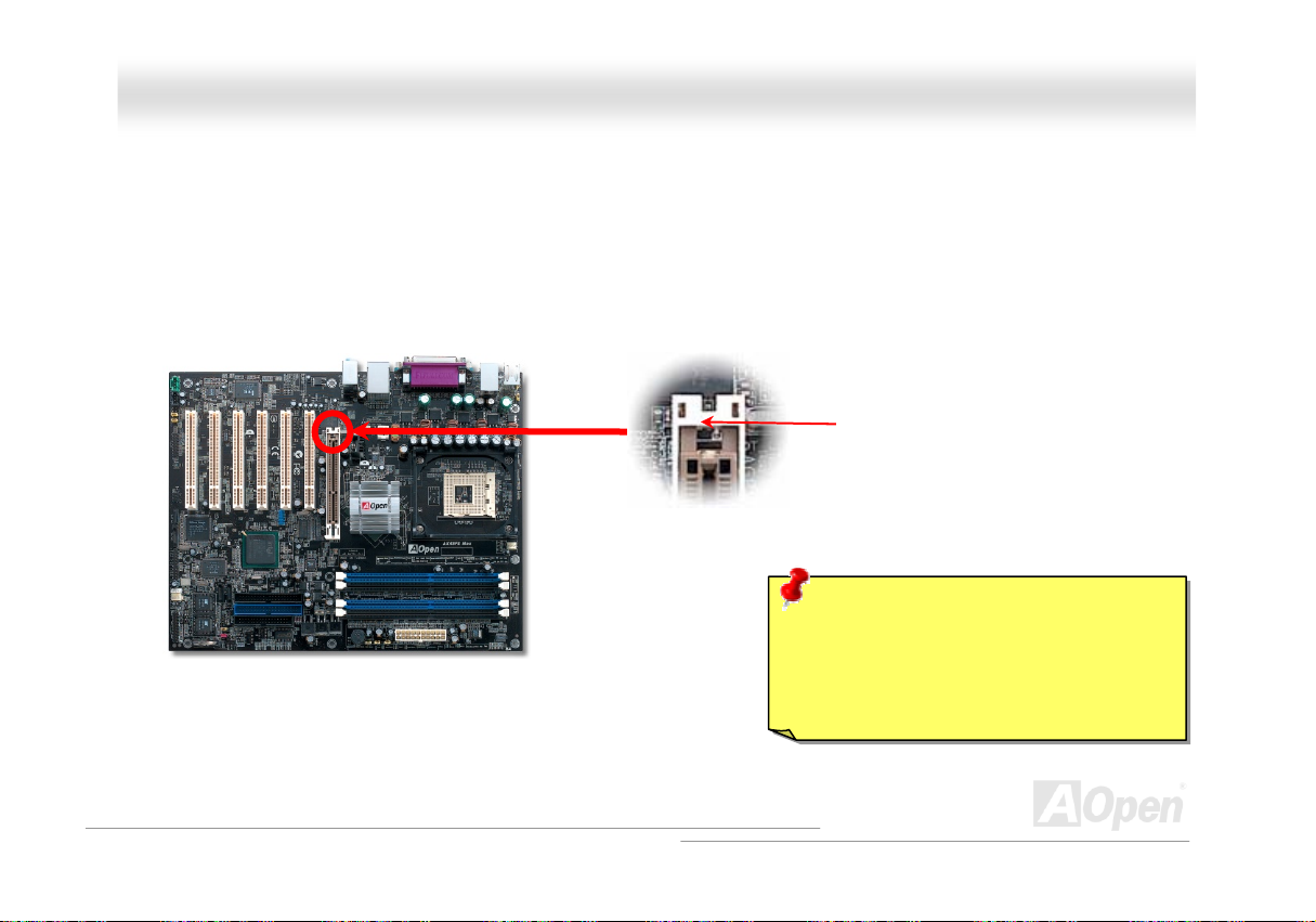
DDiiee--HHaarrdd BBIIOOSS
Many viruses have been found that they may destroy bios code and data area lately. This motherboard implements a very effective
hardware protection method without any software or BIOS coding involved, therefore it is 100% virus free. You may restore the originally
mounted BIOS with 2
may contact our local distributors or resellers for purchasing an extra BIOS ROM. Please visit our website at
nd
P
P
BIOS ROM by setting JP24 to pin 2-3 if it fails to work properly. This motherboard comes with one BIOS ROM, you
HTUwww.aopen.comUTH for details.
Pin1
1
Normal Rescue ROM
1
JP24
JP24
58
Page 59

AAXX44SSPPEE MMaaxx OOn
nlliinnee MMaannuuaall
59
Page 60

p
AAXX44SSPPEE MMaaxx OOn
nlliinnee MMaannuuaall
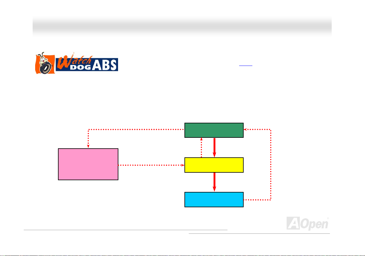
JJPP1155//JJPP1166 DDrr.. VVooiiccee LLaanngguuaaggee SSeelleecctt JJuummppeerrss
Dr. Voice is a great feature of AX4SPE Max, which can identify the problems you may encounter in the operating system. It can
clearly “tell you” whether the problem is caused from components or improper installation such as CPU, memory module, VGA,
PCI add-on card, FDD, HDD or keyboard. Dr. Voice provides four language versions: English, German, Japanese and Chinese.
You can select your preferred language by JP15 & JP16 jumpers. However, you may also set JP2 to choose making out voices
from buzzer or speaker.
JP15
Pin1
Pin1
Dr. Voice Language
Select Jum
er
(Default)
Japanese
Chinese
German
English
JP16
JP15
JP16
Pin1 Pin1
60
Page 61
(
)
AAXX44SSPPEE MMaaxx OOn
nlliinnee MMaannuuaall
JJPP22 SSppeeaakkeerr OOuuttppuutt JJuummppeerr
This motherboard comes with another considerate option that allows you to turn off the voice from buzzer and speaker. You can choose not
to be bothered by the warning made from Dr. Voice when it detects any error in operating system. You may also set JP2 to choose sending
out voices from buzzer or speaker.
Pin 1
JP2 Speaker Output Jumper
1
Buzzer
default
1
Speaker
61
Page 62

AAXX44SSPPEE MMaaxx OOn
nlliinnee MMaannuuaall
CCDD AAuuddiioo CCoonnnneeccttoorr
This connector is used to connect CD Audio cable from CDROM or DVD drive to onboard sound.
CD-IN Connector
L
GND
GND
R
Note: Though some of the latest versions of Windows
support “Digital Audio” through IDE bus. However, in
order to use Open Jukebox player, which is driven under
BIOS, it is a MUST to connect audio cable to CD-IN
connector on the motherboard.
62
Page 63
AAXX44SSPPEE MMaaxx OOn
nlliinnee MMaannuuaall
AAUUXX--IINN CCoonnnneeccttoorr
This connector is used to connect MPEG Audio cable from MPEG card to onboard sound.
L
GND
GND
R
AUX-IN Connector
63
Page 64

AAXX44SSPPEE MMaaxx OOn
nlliinnee MMaannuuaall
CCaassee OOppeenn CCoonnnneeccttoorr
The “CASE OPEN” header provides chassis intrusion-monitoring function. To make this function works, you have to enable it in the system
BIOS, connect this header to a sensor somewhere on the chassis. So, whenever the sensor is triggered by lights or by the opening of the
chassis, the system will beep to inform you. Please be informed that this useful function only applies to advanced chassis, you may
purchase an extra sensor, attach it on your chassis, and make a good use of this function.
1
GND
Sensor
Pin 1
Case Open Connector
64
Page 65

AAXX44SSPPEE MMaaxx OOn
nlliinnee MMaannuuaall
SSTTBBYY LLEEDD ((SSttaannddbbyy LLEEDD))
STBY LED is AOpen’s considerate design that we aim at providing you friendly system information. The STBY LED will light up when power
is provided to the motherboard. This is a convenient indication for you to check the system power status in many circumstances such as
power on/off, stand-by mode and RAM power status during Suspend to RAM mode.
Warning: Do not install or remove the
DIMM module or others devices when the
STBY LED lights on.
STBY LED
65
Page 66

AAXX44SSPPEE MMaaxx OOn
nlliinnee MMaannuuaall
RReesseettaabbllee FFuussee
Traditional motherboard uses fuses to prevent Keyboard and USB port from over-current or shortage. These fuses are soldered onboard
that when it is broken (function to protect motherboard), user cannot replace them and result in malfunction of motherboard.
With expensive Resetable Fuse, the motherboard can be resumed back to normal function even after the fuse had done its protection job.
Resetable Fuse
66
Page 67

AAXX44SSPPEE MMaaxx OOn
nlliinnee MMaannuuaall
EEnnllaarrggeedd AAlluummiinnuumm HHeeaattssiinnkk
Cool down CPU and Chipset are important for system reliability. Enlarged aluminum heat sink provides better heat consumption especially
when you are trying to over-clock the CPU.
67
Page 68

AAXX44SSPPEE MMaaxx OOn
nlliinnee MMaannuuaall
LLooww EESSRR CCaappaacciittoorr
The quality of low ESR capacitor (Low Equivalent Series Resistance) during high frequency operation is very important for the stability of
CPU power. The idea of where to put these capacitors is another know-how that requires experience and detail calculation.
Not only that, AX4SPE Max implements 3300μF capacitors, which is much larger than normal capacitor (1000 & 1500μF) and it provi des
better stability for CPU power.
68
Page 69

AAXX44SSPPEE MMaaxx OOn
The power circuit of the CPU core voltage must be checked to ensure system stability for high speed CPUs. A typical CPU core voltage is
2.0V, so a good design should control voltage between 1.860V and 2.140V. That is, the transient must be below 280mV. Below is a timing
diagram captured by a Digital Storage Scope, it shows the voltage transient is only 143mv even when maximum 60A current is applied.
Note: This diagram for example only, it may not be exactly the same as the motherboard you purchased.
nlliinnee MMaannuuaall
69
Page 70

AAXX44SSPPEE MMaaxx OOn
nlliinnee MMaannuuaall
TThhee nnooiissee iiss ggoonnee!!!! -------- SSiilleennttTTeekk
As the clock of CPU keeps rocketing higher and higher, it inevitably brings higher heat and
system temperature in a relative way. The way we deal with this heat problem, however, is to
spare no effort to add one fan after another to protect our pampered system, expecting these
fans could cool down our machine as much as they could.
But at the same time, we believe that same users are affected terribly by the irritating noises of these fans while working with their
PC. As a matter of fact, we do not have to get our fans running at such a high speed in most cases; on the contrary, we discovered
that having your fans running at appropriate
time and speed not only reduces the noise,
but also consumes the least power the
system needs, so as to prevent over-wasting
of energy resource.
Today, AOpen Motherboard is honored to
bring you a new overall solution, SilentTek, to
make your system quiet. To collocate with
hardware circuit, BIOS and the utility under
Windows, SilentTek combined
“Hardware-Status Monitoring”, “Overheat
Warning” and “Fan Speed Control” with
user-friendly interfaces to provide you a
perfect balance among noises, system
performance and stability.
70
Page 71

AAXX44SSPPEE MMaaxx OOn
nlliinnee MMaannuuaall
The first image you have here is the Voltage Status
page. You can find current status of all voltages and set
your expected margins of warning level.
You may check your
system voltage from the
indicating bar here.
In “Temp/Fan/Case” page, you may get aware of the
current temperature of CPU and the heat inside chassis.
Also, you can check if fans are running properly.
Of course, you may set your
defaulted lowest margin for
your fans and SilentTek would
also pop up a message box to
alarm you when the fan is
rotating slower than this
specified speed.
You may set the highest
margin of your CPU and
system temperature as
default, and SilentTek would
pop up a message box to alert
you with alarm when the
temperature goes beyond the
specified margin.
71
Page 72

AAXX44SSPPEE MMaaxx OOn
The following page is surely the most important part of this utility. You may control the rotation speed of specific fans that you have got the
options inside in this page.
CD-ROM Rotation Speed Control: by enabling the CD-ROM
Rotation Speed Control, you can adjust the rotation speed of your
CD-ROM. When you set the speed to high level, the CD-ROM will
work at its fastest speed and it will run at basic required speed
while you set the value to low speed.
1. Smart FAN Control: This is the default setting of
SilentTek and can be used for any branded computer
housing. With a special algorithm developed by AOpen,
the fan speed is automatically adjusted by the factors of
CPU and ambient temperature. Ease-of-use and trouble
free at your service.
2. Fixed FAN Control: Under this setting, a desired fan
speed is set fixed when operating.
3. Multiple Level Control: This is the most versatile
setting that allows you to set fan speed in relation to
temperature. You may find that this setting fits you best.
4. AOpen Recommend Setting: This setting is designed
specifically for AOpen housing. A series of lab tests were
conducted under the real world scenario to determine
optimum fan speed to reduce noise level within CPU
working condition and temperature. Most of the time, the
fan would remain still when CPU is not fully utilized.
Note: Due to hundreds different brands of fan on the
market, inaccuracy may happen in some cases when you
had your rotation speed adjusted. It is still under the
criterion and please rest assured that it won’t cause any
problem to your system.
nlliinnee MMaannuuaall
72
Page 73

AAXX44SSPPEE MMaaxx OOn
nlliinnee MMaannuuaall
EEzzCClloocckk
Have you ever thought how great it would be if you can adjust the frequency setting on your motherb oard under Windows environme nt an d
be a real master of your system? Everybody knows that the ratio and frequency setting are key factors to influence the system performance,
however, it’s absolutely not an easy task for an
amateur to adjust the setting value. On most
traditional motherboards, you have to get into BIOS
screen for the frequency and reboot the system
again and again. But from now on, you don’t have to
surfer the boring stuffs anymore.
With brand-new and user-friendly EzClock that
AOpen specially designs for his users, you can
adjust those important values as you please and
think of suitable. This tailor-made EzClock allows you
to set the voltage and frequency of CPU, VGA, PCI
and memory under Windows environment as well as
in BIOS setting page; even better, those settings will
be displayed realtime. Having this handy EzClock,
you can monitor the system when you’re fine-tuning
the performance of your system. It provides you
detailed and necessary information. Now let’s take a
look how it works on utility, BIOS and POST.
73
Page 74
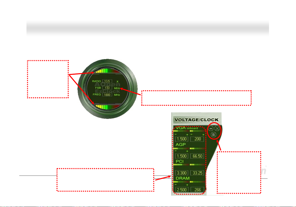
AAXX44SSPPEE MMaaxx OOn
nlliinnee MMaannuuaall
How You Adjust the Settings in EzClock Utility
In EzClock utility, you can adjust CPU Front Side Bus (FSB), the voltage and frequency of VGA, AGP, PCI and DRAM. Besides, the CPU
related information such as CPU voltage, temperature and CPUFAN rotation speed will also be displayed on this utility.
CPU Color Bars:
The color bar will
light on and show
different colors as
values change. On
default values, it
will show green.
On the right part of the panel is the section that you adjust the settings of
VGA, AGP, PCI and memory. To adjust the voltage and clock frequency of
those installments, you can press “-“ or “+” on corresponding items. The
color parts represent the situation of values. The higher value you set, the
light on the color bar goes to right and turns red. After finishing those value
settings, you can press “S” button on the upper right hand corner to save
changes to CMOS.
VGA, AGP, PCI and DRAM Voltage / Clock Area:
Pressing “_” and “+” buttons, you can adjust the
voltage and clock frequency values of onboard
VGA, AGP, PCI and DRAM.
On the left circle area shows Ratio, FSB and frequency information
about CPU. When the values are set to factory default, the light on
the top and bottom of the circle will show green and it will vary as you
change these CPU settings.
CPU Ratio, FSB and frequency displaying area:
You can adjust CPU FSB here by entering preferred value.
74
Control buttons:
“_” button allows
you to minimize the
utility and “X” button
to close the utility.
Pressing “S” button
you can save the
changes to CMOS.
Page 75

p
AAXX44SSPPEE MMaaxx OOn
On the bottom rectangular panel represents CPU fan speed, CPU voltage and CPU temperature. The three color bars on the right hand
side will light on according to operation temperature. Please refer to the picture shown above.
CPU Color Bars:
The color bars will light on
according to CPU operation
erature.
tem
CPU Fan, Voltage and Temperature:
representing CPU fan speed, CPU
voltage and CPU temperature in
Celsius and Fahrenheit degrees.
nlliinnee MMaannuuaall
How You Adjust the Settings in BIOS
Apart from EzClock utility, the voltage and frequency values of CPU, PCI and memory can also be adjusted on BIOS page. By pressing “+”,
“-“, “PgUp” or “PgDn” keys, you can adjust
the frequency values of CPU Bus, PCI Bus
and DRAM.
Also, the same keys help you adjust the
voltage of CPU and DDR settings. Some
values may change while you adjust the
settings. You can press “F10” to save the
changes you’ve made.
Function Keys
Description
75
Page 76
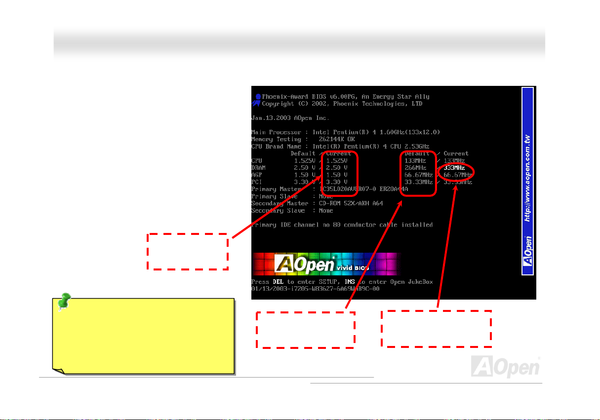
AAXX44SSPPEE MMaaxx OOn
How Your Boot Screen Looks Like
After you finish setting BIOS, these setting values will
be displayed on the boot screen like the shown
picture here.
Every time you boot your system, both default and
current settings will pop up on the screen. Your
personal settings that had been adjusted earlier will
be highlighted; thus, you can have clear idea how
your system functions and monitor your system more
easily.
NOTE: Due to BIOS versions are updated
in an extremely fast speed, it's strongly
recommended to download the latest
version of EzClock from our website for best
compatibility.
Current values of
your system
Default settings of this
motherboard
The highlighted setting
value you manually adjust
nlliinnee MMaannuuaall
76
Page 77

AAXX44SSPPEE MMaaxx OOn
nlliinnee MMaannuuaall
HHyyppeerr TThhrreeaaddiinngg TTeecchhnnoollooggyy
What is Hyper-Threading?
Hyper-Threading technology is an innovative design from Intel that enables multi-threaded software applications to process threads in
parallel within each processor resulting in increased utilization of processor execution resources. As a result, an average improvement of
~40% in CPU resource utilization yields higher processing throughput.
How Hyper-Threading Works
A form of simultaneous multi-threading technology (SMT), Hyper-Threading technology allows multiple threads of software applications to
be run simultaneously on one processor by
duplicating the architectural state on each
processor while the same processor execution
resources is shared. The figure below
represents how a Hyper-Threading based
processor differentiates a traditional
multiprocessor. The left-hand configuration
shows a traditional multiprocessor system with
two physical processors. Each processor has its
own independent execution resources and
architectural state. The right-hand configuration
represents an Intel Hyper-Threading technology
based processor. You can see that the
architectural state for each processor is
duplicated, while the execution resources is
shared.
77
Page 78

AAXX44SSPPEE MMaaxx OOn
For multiprocessor-capable software applications, the Hyper-Threading based processor is considered two separate logical processors on
which the software applications can
run without modification. Also, each
logical processor responds to
interrupts independently. The first
logical processor can track one
software thread, while the second
logical processor tracks another
software thread simultaneously.
Because the two threads share the
same execution resources, the second
thread can use resources that would
be otherwise idle if only one thread
was executing. This results in an
increased utilization of the execution
resources within each physical
processor.
The figure below represents how
Hyper-Threading saves time when it
works. With two logical processors available on every single physical processor, multi-threaded applications can now take advantage of
thread-level parallelism on each physical processor for additional performance. As software applications continue to be optimized to take
greater advantage of processor parallelism, Hyper-Threading technology provides an additional boost for newer capabilities and the
growing needs of today’s users.
nlliinnee MMaannuuaall
78
Page 79

AAXX44SSPPEE MMaaxx OOn
nlliinnee MMaannuuaall
AAOOCCoonnffiigg UUttiilliittyy
AOpen always dedicated to provide users a much friendly computer environment. We now
bring you a comprehensive system detection utility. AOConfig is a Windows based utility with
user-friendly interface that allows users to obtain information of the operation system and
hardware such as motherboard, CPU, memory, PCI devices and IDE devices. The powerful utility also displays the version of BIOS and
firmware for your convenience of maintenance.
Moreover, AOConfig allows users to save information in *.BMP or *.TXT format which users may collect the system information in detail and
send them to AOpen directly for technical support or for further diagnose of system problems.
1. The system page shows the
detailed information of the
motherboard, operating
system, processor, and
BIOS version.
2. The PCI device page shows
the configurations of all PCI
devices installed in your
motherboard.
79
Page 80

AAXX44SSPPEE MMaaxx OOn
3. This page presents the IDE
device information, such as
serial number, manufacturer,
firmware version, and capacity.
4. From this page, users can
obtain the technical support
information of AOpen. Moreover,
detailed information could be
saved in .bmp or .txt format.
NOTE:
AOConfig can be used under Windows 98SE/ME, NT4.0/2000, or Windows XP. Please also note that AOConfig can
only be operated in a system equipped with an AOpen motherboard. Before running AOConfig, all applications must
be closed.
nlliinnee MMaannuuaall
80
Page 81

AAXX44SSPPEE MMaaxx OOn
nlliinnee MMaannuuaall
RRAAIIDD IInnttrroodduuccttiioonn
WWhhaatt’’ss RRAAIIDD??
Two major challenges facing the storage industry today are keeping pace with the increasing performance demands of computer systems
by improving disk I/O throughput and providing data accessibility in the face of hard disk failures.
The idea of RAID (Redundant Array of Independent Disks) was first introduced by David A. Patterson, Garth Gibson and Randy H. Katz at
the University California at Berkeley in 1988. RAID is a purpose of storing the same data in different places on multiple
improves storage subsystem performance. The advantage of RAID is to provide better throughput performance and/or data fault tolerance.
Better performance is accomplished by sharing the workload in parallel among multiple physical hard drives. Fault-tolerance is achieved
through data redundant operation where if one (or more) drive fails or has a sector failure, a mirrored copy of the data can be found on
another drive(s).
A RAID appears to the operating system to be a single logical hard disk. The RAID controller manages how the data is stored and
accessed across the physical and logical arrays. The RAID controller help users to ensure that the operating system only sees the logical
drives and users do not need to worry about managing the complicated schema.
For optimal performance results, select identical hard drives to install in disk arrays. The drives’ matched performance allows the array to
function better as a single drive.
Warning: The Serial ATA RAID function
can be supported under Windows XP and
Windows .Net environments.
Hhard diskHs and
81
Page 82

AAXX44SSPPEE MMaaxx OOn
nlliinnee MMaannuuaall
WWhhaatt aarree tthhee RRAAIIDD lleevveellss??
SSttrriippiinngg // SSppaann ((RRAAIIDD 00))
RAID level 0, which is the fastest drive array you can have, is a performance-oriented disk mapping method. The data in this array gets
written across a stripe or different disks for a faster transfer. This technique has striping but no redundancy of data. It offers the best
performance but no fault-tolerance. Reads and writes sector of data interleaved between multiple drives. When any disk member fails, it
affects the entire array. Performance is better than a single drive since the workload is balanced between the array members. This array
type is for high performance systems. Identical drives are recommended for perfor mance as well as data storage efficiency. The disk array
data capacity is equal to the number of members times the smallest member capacity. For example, one 40GB and one 60GB drives will
form an 80GB (40GBx2) disk array.
Block 1
Block 2
Block 3
Block 4
Striping
Block 1
Block 3
Block 5
Block 7
Block 5
Block 6
Block 7
Block 8
Block 2
Block 4
Block 6
Block 8
Logical Drive
82
Physical Disks
Page 83

AAXX44SSPPEE MMaaxx OOn
nlliinnee MMaannuuaall
MMiirrrroorriinngg ((RRAAIIDD 11))
RAID level 1 uses at least two duplicate hard drives and store the exact same
blocks of information between them. This is the slowest form of fault
tolerance because the data has to be replicated onto two disks at the same
time. However, this is the simplest way to provide high reliability.
If one of the mirrored drives suffers a mechanical failure or does not respond,
the remaining drive will continue to serve and provide correct data. If one
drive has a physical sector error, the mirrored drive will continue to function.
Due to redundancy, the drive capacity of the array is half the total drive
capacity. For example, two 40GB drives that have a combined capacity of
80GB would have 40GB of usable storage. With drives of different capacities,
there may be unused capacity on the larger drive. RAID 1 increases cost as it
takes twice as much hard drives to build our arrays.
Block 1
Block 2
Block 3
Block 4
Block 5
Block 6
Block 7
Block 8
Logical Drive
Mirroring
Block 1
Block 2
Block 3
Block 4
Block 5
Block 6
Block 7
Block 8
Block 1
Block 2
Block 3
Block 4
Block 5
Block 6
Block 7
Block 8
83
Physical Disks
Page 84

AAXX44SSPPEE MMaaxx OOn
nlliinnee MMaannuuaall
SSttrriippiinngg wwiitthh MMiirrrroorriinngg ((RRAAIIDD 00++11))
As the name would suggest, RAID 0+1 is striping and mirroring combined. This RAID combines the best of both RAID 0 and RAID 1. It
takes a Disk stripe using two disks, and mirrors it to another set of disks for fault tolerance. Data is stripped across several disks, each disk
has partner with exactly the same data on it. You get the benefits of fast data access as in RAID 0, with the fault tolerance of RAID 1. This
configuration provides optimal speed and reliability. You need double the number of disks as a RAID 0, half for each side of the mirror. At
least 4 hard disks are needed while performing RAID 0+1. There is other RAID configurations in addition to those described here, but th ese
are the types most commonly used in the industry.
Block 1
Block 2
Block 3
Block 4
Block 5
Block 6
Block 7
Block 8
Logical Drive
Striping
Block 1
Block 3
Block 5
Block 7
Block 2
Block 4
Block 6
Block 8
Physical Disks
Mirroring
Mirroring
Physical Disks
Block 1
Block 3
Block 5
Block 7
Block 2
Block 4
Block 6
Block 8
84
Page 85

AAXX44SSPPEE MMaaxx OOn
nlliinnee MMaannuuaall
HHDDDD CCaappaacciittyy ooff RRAAIIDD LLeevveellss
SSttrriippiinngg // SSppaann ((RRAAIIDD 00)) S
Physical Disks
40 GB
MMiirrrroorriinngg ((RRAAIIDD 11))
Physical Disks
40 GB
Physical Disks
40 GB
Physical Disks
40 GB
Logical Drive
80 GB
Logical Drive
40 GB
Sttrriippiinngg wwiitthh MMiirrrroorriinngg ((RRAAIIDD 00 ++11))
Striping
Physical Disks 40GB
Physical Disks 40GB
Striping
Physical Disks 40 GB
Mirroring
Physical Disks 40 GB
Logical Drive
80 GB
85
Page 86

AAXX44SSPPEE MMaaxx OOn
nlliinnee MMaannuuaall
SSeerriiaall AATTAA RRAAIIDD ffoorr IInntteell IICCHH55RR
With the latest chipsets implemented, Intel ICH5R provides RAID 0 and RAID 1 function for the Serial ATA hard disks. You may follow the
steps shown below to setup your disk array.
AArroouussee RRAAIIDD ffuunnccttiioonn iinn BBIIOOSS
After having properly installed your Serial ATA hard disks, you may directly get into the BIOS setting screen for adjustment. You may simply
press “Integrated Peripherals Æ On-Chip IDE Device Æ On-Chip Serial ATA” to choose Enhanced mode. In order to utilize Serial ATA
function, please select RAID in SATA Mode. Finally, do save the changes and exit BIOS setup screen.
86
Page 87

AAXX44SSPPEE MMaaxx OOn
nlliinnee MMaannuuaall
RRAAIIDD CCoonnffiigguurraattiioonn UUttiilliittyy
In order to make sure your system can recognize and operate Serial ATA RAID device smoothly, we have to enter RAID Configuration Utility
to do some configuration. After finishing the BIOS setup and reboot, you will see [Press CTRL + I to enter configuration Utility] about half
way through the boot up. Please press these two buttons simultaneously. When you enter you will be presented with a screen as shown
below:
1. Create RAID Volume:
This section allows users to choose the strip
size and disk volume of RAID.
2. Delete RAID Volume:
This section allows users to delete the volume of
RAID. Please be noted that deleting a volume
will destroy volume data and cause any member
disks to become available as non-RAID disks.
3. Reset Disks to Non-RAID:
Users can remove any internal RAID structures
from all RAID disks, including disks with working
volume. Select “Yes” will cause all data on any
disk to be lost.
87
Page 88

AAXX44SSPPEE MMaaxx OOn
nlliinnee MMaannuuaall
SSeerriiaall AATTAA RRAAIIDD ffoorr SSiilliiccoonn IImmaaggee 33111122AA
TM
Silicon Image’s SATARaidP
PCI-to-SATA host controller product.
Standard with SATARaid software is a Graphical User Interface (GUI) that provides easy-to-use configurations for the different RAID Sets
supported.
IInnssttaalllliinngg DDrriivveerrss aanndd SSAATTAARRaaiidd GGUUII iinn WWiinnddoowwss 9988//M
The driver is located on the provided floppy disk. Insert the floppy disk into the floppy disk drive and click Browse. Most floppy disk drives
are configured as [A:]. Choose the [A:] drive in your browser and the Si3112r.inf file for the SiI 3112. Select the file and click Open.
For Windows NT system, please select the file Oemsetup.inf and click Open. The next window allows you to select which driver to install.
Select SiI 3112 Raid Controller and click on OK.
For Windows 98/ME, please use the driver installation files (siI3112r.sys) on the provided floppy disk if necessary.
Now, a window verifying that the new Driver for the board has been properly installed. Click Finish.
It is always good to restart the computer after an installation. When asked to do so, click yes.
To install SATARaid, use Windows InstallShield by performing the following:
1. After computer restarts, insert CD in disk drive.
2. Double-click on Install SATARaid.exe.
3. Follow on-screen instructions to complete installation.
Note: Do NOT install in the Start Up folder. Choose the Default folder (normally Accessories or Administrative Tools or something similar).
P
provides Serial ATA Software RAID including Striping and Mirroring to enhance the industry’s first proven
MEE//22000000//NNTT//XXPP
88
Page 89

AAXX44SSPPEE MMaaxx OOn
nlliinnee MMaannuuaall
89
Page 90

AAXX44SSPPEE MMaaxx OOn
CCrreeaattiinngg aanndd DDeelleettiinngg RRaaiidd SSeetts
Creating and Deleting RAID Sets is a function set in the BIOS and please press <CRTL-S> or F4 to enter RAID utility during boot.
Creating RAID Sets
1. Select “Create RAID Set”.
2. Choose either a “Striped” or “Mirrored” RAID Set.
3. Select if you want the utility to Auto Configure the RAID Set or if you want to manually configure the RAID Set.
For Striped Sets, you can change the chunk size. For Mirrored Sets, you assign which is the Source and Target drives, as well as if you
want Disk Copy.
The utility will ask “Are You Sure?” before completing the configuration.
Deleting RAID Sets
1. To remove one or more RAID sets, select “Delete RAID Set”.
2. Select desired set and press Y when asked “Are You Sure?”
s
nlliinnee MMaannuuaall
90
Page 91

AAXX44SSPPEE MMaaxx OOn
nlliinnee MMaannuuaall
CCrreeaattiinngg aanndd NNaammiinngg PPaarrttiittiioonnss
The creating and naming of partitions is something done within the Windows operating system. Windows XP/2000 and Windows NT both
use the Disk Management window to start this work. And Windows 98/ME uses FDISK to realize this function.
Windows XP/2000
SECTION 1: System listing of all formatted and available disks/RAID Sets.
SECTION 2: Report of physical connection of disks/RAID Sets.
SECTION 3: Report of partition status, disk letter, and volume name.
Windows NT
Button 1: opens the Disk Administrator Volumes window which lists the
recognizable Volumes, their capacity, free space, type of format, etc.
Button 2: opens the Disk Configuration window (shown above), detailing
all disks (or RAID Sets), partitions, and allows he sure to format and
name each partition and volume.
Section 1: reports the size of each disk (or RAID Set).
Section 2: reports on each partition, and allows the user to format or
delete partitions.
91
Page 92

AAXX44SSPPEE MMaaxx OOn
nlliinnee MMaannuuaall
UUssiinngg SSiilliiccoonn IImmaaggee SSAATTAARRaaiidd GGUUII
The SATARaid GUI offers the user the ability to easily monitor your RAID Set. To launch the GUI, simply double-click on the icon located in
the bottom right hand corner of the Desktop.
92
Page 93

AAXX44SSPPEE MMaaxx OOn
nlliinnee MMaannuuaall
PPhhooeenniixx--AAWWAARRDD BBIIOOSS
System parameters can be modified by going into HTUBIOSUTH Setup menu, this menu allows you to configure the system parameters and save
the configuration into the 128 bytes CMOS area, (normally in the RTC chip or in the main chipset).
Phoenix-Award BIOS™ installed in the
provides critical low-level support for standard devices such as hard disk drives, serial and parallel ports.
Most BIOS settings of AX4SPE Max have been optimized by AOpen’s R&D engineering team. But, the default setting of BIOS still can’t
fine-tune the chipset controlling entire system. Therefore, the rest of this chapter intends to guide you the process of configuring your
system setup.
To enter to BIOS setup menu, press <Del> when
HTUFlash ROMUTH of the motherboard is a custom version of an industry standard BIOS. The BIOS
HTUPOST (Power-On Self Test)UTH screen is shown on your monitor.
Note: Because the BIOS code is the most often
changed part of the motherboard design, the BIOS
information contained in this manual may be different
with actual BIOS that come with your motherboard.
93
Page 94

AAXX44SSPPEE MMaaxx OOn
nlliinnee MMaannuuaall
HHooww TToo UUssee PPhhooeenniixx--AAwwaarrdd™™ BBIIOOSS SSeettuupp PPrrooggrraamm
Generally, you can use arrow keys to highlight items that you want to choose, then press <Enter> key to select, and use the <Page Up>
and <Page Down> key to change setting values. You can press <Esc> key to quit Phoenix-Award™ BIOS setup program. The following
table provides details about how to use keyboard in the Phoenix-Award BIOS setup program. Alternatively, it's strongly recommended to
install AOpen’s newest
HTUWinBIOS UtilityUTH to get more detailed description, further powerful functions and advanced setting of BIOS.
Key Description
Page Up or + Changing setting to next value or increase the value.
Page Down or - Changing setting to previous value or decrease value.
Enter Select the item.
Esc 1. In main menu: Quit and don’t save any change.
2. In sub menu: Exit current menu to main menu.
Up Arrow Highlight previous item.
Down Arrow Highlight next item.
Left Arrow Move the light bar to left side of menu.
Right Arrow Move the light bar to right side of menu.
F6 Load fail-save setting value from CMOS.
F7 Load turbo setting value from CMOS.
F10 Save changed setting and exit setup program.
94
Page 95

AAXX44SSPPEE MMaaxx OOn
nlliinnee MMaannuuaall
HHooww TToo EEnntteerr BBIIOOSS SSeettuupp
After you finish jumper settings and connect correct cables, power on and enter the BIOS Setup. Press <Del> during HTUPOSTUTH (Power-On Self
Test) and choose "Load Setup Defaults" for recommended optimal performance.
Del
Warning: Pleas e avoid of using "Load Turbo Defaults", unless you
are sure your system components (CPU, DRAM, HDD, etc.) are
good enough for turbo setting.
95
Page 96

AAXX44SSPPEE MMaaxx OOn
nlliinnee MMaannuuaall
WWiinnBBIIOOSS UUttiilliittyy
timing during POST (Power-On-Self-Test) screen to get into the
BIOS, which is inconvenient and clumsy. From now on, AOpen
provides an easier way to configure your BIOS. WinBIOS is a
customized utility for running exclusively on AOpen motherboards,
which allows you to setup your BIOS under Windows environment.
Designed with traditional-BIOS-alike interface, you may adjust BIOS
parameter with clear descriptions for each item.
WinBIOS is natively designed with multi-language support. There
are various widely-use languages provided on our website for your
downloading, which also helps to prevent wrong settings caused by
misunderstanding of the languages. The only thing you have to do
is to visit our official website and download your respective
language pack (of few KB size), then double-click on it to activate
the support with your chosen language.
Moreover, with high scalability, either for newly bought motherboard or the latest BIOS version with new function, you don’t have to
re-install the whole program again and again. All you have to do is to grab the latest profile from our website, simply double-click on
it as well to support the latest version of your BIOS. You don’t have to spend any extra effort to have your motherboard supported
by WinBIOS.
In the past, users have to keep
punching the DEL key at a good
96
Page 97

AAXX44SSPPEE MMaaxx OOn
nlliinnee MMaannuuaall
Function keys:
It’s definitely easy to handle WinBIOS as if you’re using traditional
BIOS setting. Users can use the arrow keys such as
to move around the items in WinBIOS screen. And use
“+” or “-” to change the setting value if they are available. Press
get back to the previous screen. Furthermore, the hotkeys shown in the
table may help you and save your time. Some settings may not come
into effect until you reboot your system.
TCaution: After updating your BIOS, please remember to update
WinBIOS profile as well. If the upgraded BIOS version is newer
than WinBIOS profile, WinBIOS will not be able to launch and a
dialog box with error message will pop up. This verification is
designed on purpose to protect your BIOS from damaged by
wrong profile version.
For the latest WinBIOS profile and language pack modules, you may
find them from AOpen official web site as shown below:
HTUhttp://english.aopen.com.tw/tech/download/WinBIOS/default.htmUTH)
(
Note: Due to BIOS versions are updated in an extremely fast speed, it's strongly recommended to download the latest BIOS
version and WinBIOS profile from our website upon receipt of the motherboard.
Hotkey Function Description
F1 Get help description.
F2 Item Help
,
F3 Changing menu language.
to
F5 Load previous setting
F6 Load setup default setting
F7 Load turbo setting
F10 Save changed setting and exit setup program.
F12 Full Screen / Normal Mode
97
Page 98

AAXX44SSPPEE MMaaxx OOn
nlliinnee MMaannuuaall
BBIIOOSS UUppggrraaddee uunnddeerr WWiinnddoowwss eennvviirroonnmmeenntt
With outstanding R&D ability of AOpen, we now bring you a whole new BIOS Flash wizard ----
EzWinFlash. With an eye to users convenience, EzWinFlash combines the BIOS binary code
and flash module together, so the only thing you have to do is just clicking on the utility you downloaded from web and let it helps you
complete the flash process automatically. EzWinFlash detects your motherboard and checks the BIOS version cleverly to prevent your
system from any possible failure. Moreover, EzWinFlash has been taken into consideration to go with any windows platform you might be
using, no matter if you’re using Windows 95/98, 98SE/ME, NT4.0/2000, or Windows XP.
In the meanwhile, in order to provide a much more user-friendly operating environment, AOpen EzWinFlash is natively designed to have
multi-language function to provide easier way for users’ usage in changing BIOS setting.
TCaution: TBy updating your motherboard,
you are taking a risk of BIOS flash failure. If
your motherboard is working stable, and
there are no major bugs that had been fixed
by a latter BIOS revision, we recommend
that you DO NOT try to upgrade your BIOS.
If you intent on upgrading, PLEASE BE
SURE to get the right BIOS revision for the
right motherboard model to avoid any
possibility failure.
98
Page 99

AAXX44SSPPEE MMaaxx OOn
You may accomplish BIOS upgrade procedure with EzWinFlash by the following steps, and it’s STRONGLY RECOMMENDED to close all
the applications before you start the upgrading.
1. Download the new version of BIOS package
2. Unzip the download BIOS package (ex: WSPEMAX102.ZIP) with WinZip (
3. Save the unzipped files into a folder, for example, WSPEMAX102.EXE & WSPEMAX102.BIN.
4. Double click on the WSPEMAX102.EXE; EzWinFlash will detect the model name and BIOS version of your motherboard. If you had
got the wrong BIOS, you will not be allowed to proceed with the flash steps.
5. You may select preferred language in the main menu, then click [Start Flash] to start the BIOS upgrade procedure.
6. EzWinFlash will complete all the process automatically, and a dialogue box will pop up to ask you to restart Windows. You may click
[YES] to reboot Windows.
7. Press <Del> at POST to enter BIOS setup; choose "Load Setup Defaults", then “Save & Exit Setup”. Done!
It is strongly recommended NOT to turn off the power or run any application during FLASH PROCESS.
Warning: The new BIOS upgrade will permanently replace your
original BIOS’s settings when flashing. You may need to reconfigure
your BIOS setting so that your system can go back to work as normal.
HTUzipUTH file from AOpen official web site. (ex: HTUhttp://www.aopen.comUTH)
HTUhttp://www.winzip.comUTH) in Windows environment.
nlliinnee MMaannuuaall
99
Page 100

AAXX44SSPPEE MMaaxx OOn
nlliinnee MMaannuuaall
VViivviidd BBIIOOSS tteecchhnnoollooggyy
Unlike earlier graphic POST screen which could occupy the whole screen and mask text information during POST, AOpen VividBIOS deals
with graphics and texts separately, and makes them running simultaneously during POST. With this innovative design, VividBIOS now
brings you a beautiful and sleek 256 colours screen without missing any important information shown on POST screen.
In addition, the limited space of BIOS ROM is another big issue. When all of the traditional BIOS can only show space-consuming and
uncompressed Bitmap, AOpen has considerately tuned the BIOS to next generation, to recognize the smaller-sized GIF format and even
dynamic-showing GIF animation.
Vivid BIOS shares the same fundamental technology with Open JukeBox CD Player, you may use the same EzSkin utility to change your
Vivid BIOS screen or to download your favourite Open JukeBox skin. If you see this little logo
the BIOS download page,
innovative feature!
HTUhttp://english.aopen.com.tw/tech/download/skinUTH, it is assured that your motherboard supports this
Have you been fed up with the conservative and immutable POST screen? Let’s rule out the tradition
idea that POST screen are stiff and frigid, and let AOpen show you the newly developed VividBIOS to
experience the lively vivid colourful POST screen!
shown beside your model name on
100
 Loading...