

Page 1
N17XA22-2
S
S
E
E
R
R
VII
V
C
C
E
E
M
M
A
A
N
N
U
U
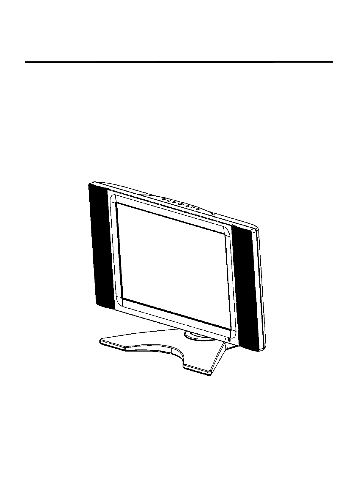
LCD TV MONITOR
N17XA22-2
A
A
L
L
THESE DOCUMENTS ARE FOR REPAIR SERVICE INFORMATION ONLY. EVERY REASONABLE EFFORT
HAS BEEN MADE TO ENSURE THE ACCURACY OF THIS MANUAL; WE CANNOT GUARANTEE THE
ACCURACY OF THIS INFORMATION AFTER THE DATE OF PUBLICATION AND DISCLAIMS RELIABILITY
FOR CHANGES, ERRORS OR OMISSIONS.
-1-
Page 2

N17XA22-2
2
Table of Content
Revision List…………………………………………………………………………………………………………
3
1. General Specifications…………………………………………………………………………………………..
4
2. Operating Instructions…………………………………………………………………………………………..
5
2.1 The Use Of Remote Control……………………………………………………………….…………………
5
2.2 To Use The Menus……………………………………………………………………………….……………
6
2.3 LCD TV Description……………………………………………………………………………………………
10
2.4 Interface Connector…………………………………………………………………………………………..
10
3. Precautions and Notes………………………………………………………………………………………….
11
3.1 Assembly Precaution……………………………………………………………….…………………………
11
3.2 Operation Precaution………………………………………………………………….………………………
11
3.3 Storage Precaution……………………………………………………………………………………………
11
3.4 High Voltage Warning………………………………………………………………………………………..
11
4. D-SUB Pin Distribution……………………………………………………………………………….…………
12
4.1 D-SUB Connector……………………………………………………………………………………………..
12
4.2 Factory Preset Display Modes………………………………………………………………………………
13
5. Adjustment………………………………………………………………………………………………….…….
14
5.1 Adjustment Control Function…………………………………………………………………………………
14
5.2 Front Panel Control Knobs…………………………………………………………………………………...
14
6. Repair Flow Chart………………………………………………………………………………….…………….
15
7. White-Balance, Luminance adjustment…………………………………………………………….………..
19
8. Parts List of Cabinet……………………………………………………………………………………………..
21
9. PCB Layout………………………………………………………………………………………………………
44
9.1 Main Board ……………………………………………………………………………………………………
44
9.2 Power Board ………………………………………….……………………………………………………….
46
9.3 Key Board ………………………………….………………………………………………………………….
48
9.4 Headphone Board …………………………….………………………………………………………………
48
9.5 IR Board ……………………….………………………………………………………………………………
48
10. Block Diagram…………………………………………………………………………………………………..
49
10.1 Main Board……………………………………………………………………………………………………
49
10.2 Power Board………………………………………….………………………………………………………
50
11. Schematic Diagram…………………………………………………………………………………………….
51
11.1 Main Board……………………………………………………………………………………………………
51
11.2 Power Board…………………………………………………………………………….……………………
64
11.3 Key Board……………………………………………….…………………………………………………….
67
11.4 Headphone Board………………………………………………………………………….………………
67
11.5 IR Board Board……………………………………………….………………………………………………
68
- -
Page 3

N17XA22-2
3
Version
Date
Revision History
TPV Model Name
A00
May-19-06
Initial Release
E764FSNBA2N22M
Revision List
- -
Page 4
N17XA22-2
4
Items
Specification
LCD Panel
Screen Size
17” TFT-LCD Panel
Aspect Ratio
15:9
Resolution
1280 x 768 (WXGA)
Display Area (opening) H x V
369mm x 221mm
Pixel Pitch
0.288mm x 0.288mm
Display colors
16.7 million
Contrast Ratio
400:1
Brightness
450cd / m²
Viewing Angle
170° (Horizontal)/ 170° (Vertical)
Response Time
25ms
Lamp Type/Life
60000 hr
Color Temperature
Cool / Warm
TV Function
TV Standard
PAL B/G, D/K, I and SECAML/L’
Full Channel with Electronic PLL Tuner
Sound systems
NICAM/ A2
Video Inputs
SCART
RGB or CVBS ×1
Audio L/R x 1
RCA
CVBS (Composite) ×1
Audio L/R x 1
S-Video
S-Videox1
Share with CVBS
(RCA)
PC Input
Signal Input
Analog: D-Sub 15 pin (detachable cable)
PnP compatibility
DDC 2B
Input frequency
Analog: FH: 31.5kHz to 48.36kHz
FV: 60Hz to 75Hz
Recommended
Analog: 1024 x 768 (60Hz)
Input Audio
Headphone Mini-jack for stereo (3.5ø)
Audio Output
Audio Output: L / R
Speaker (built-in): Two 2 watt speakers
Headphone Mini-jack for stereo (3.5ø)
Line Output (RCA L/R)
OSD language
English / French / German / Italian / Spanish / Portuguese
Table Stand
Included
Wall Mount
VESA 100 x 100 mm
Power
Power Supply
AC100V~240V, 50/60Hz
Power Consumption
<70W
Panel Tilt
Forwards/Backwards/
Rotation
- 5° / + 20° / ± 30°
Dimension
W x H x D (with stand)
560 x 338 x 184 (mm)
Weight (net)
Kg (w/o Accessories)
6 Kg
Accessories
Remote Controller, Batteries (x2), AC Power Cord, D-sub Signal Cable, Audio
cable, Operation Manual
1. General Specifications
- -
Page 5
N17XA22-2
5
POWER
Press to turn on/off the
TV. The TV is never
completely powered off
unless it is physically
unplugged.
CH
Press ▲ or ▼ (or ▲ or
▼ button) to browse
through the TV channels
0~9 Digit buttons
Press To select a TV
channel.
VOL
Press + or –(or or )
to adjust the volume.
SOUND
To select Mono /Stereo
from TV RF input.
SLEEP
With this key you can set
a time period after which
the TV should switch itself
to standby. Press the key
repeatedly to select the
number of minutes. The
counter runs from 0, 30,
60, 90,120 minutes. The
timer begins to count
down from the number of
minutes selected after the
display has disappeared.
PIP/ POP3
Press to enable
the screen of
Video on Graphic
(option)
MENU
Press repeatedly to display
OSD menu.
SIZE2
I Includes 3 modes. Press
repeatedly to select 4:3: to
16:9 (Linear) / 4:3 to 16:9
(non-Linear) /16:9 (option)
MUTE
Temporarily interrupt
the sound or restore it.
DISPLAY
(1) Display Channel number
when use RF input.
(2) Display input source
when use other input
except TV RF input.
TV/VIDEO
Select your input source: press
repeatedly to select TV, AV,
S-VIDEO or SCART mode,
according to where you connected
your external source.
PC
Select your input source to PC.
SWAP
1
Press to swap the two screens
when PIP is work (option)
SUBPAGE
Teletext Subpage function.
PRE-CH
To display the previously selected
TV channel.
2. Operating Instructions
2.1. The Use Of Remote Control
Note 1,3: SWAP, POP functions are not available on all model.
2: SIZE functions (option).
- -
Page 6
N17XA22-2
6
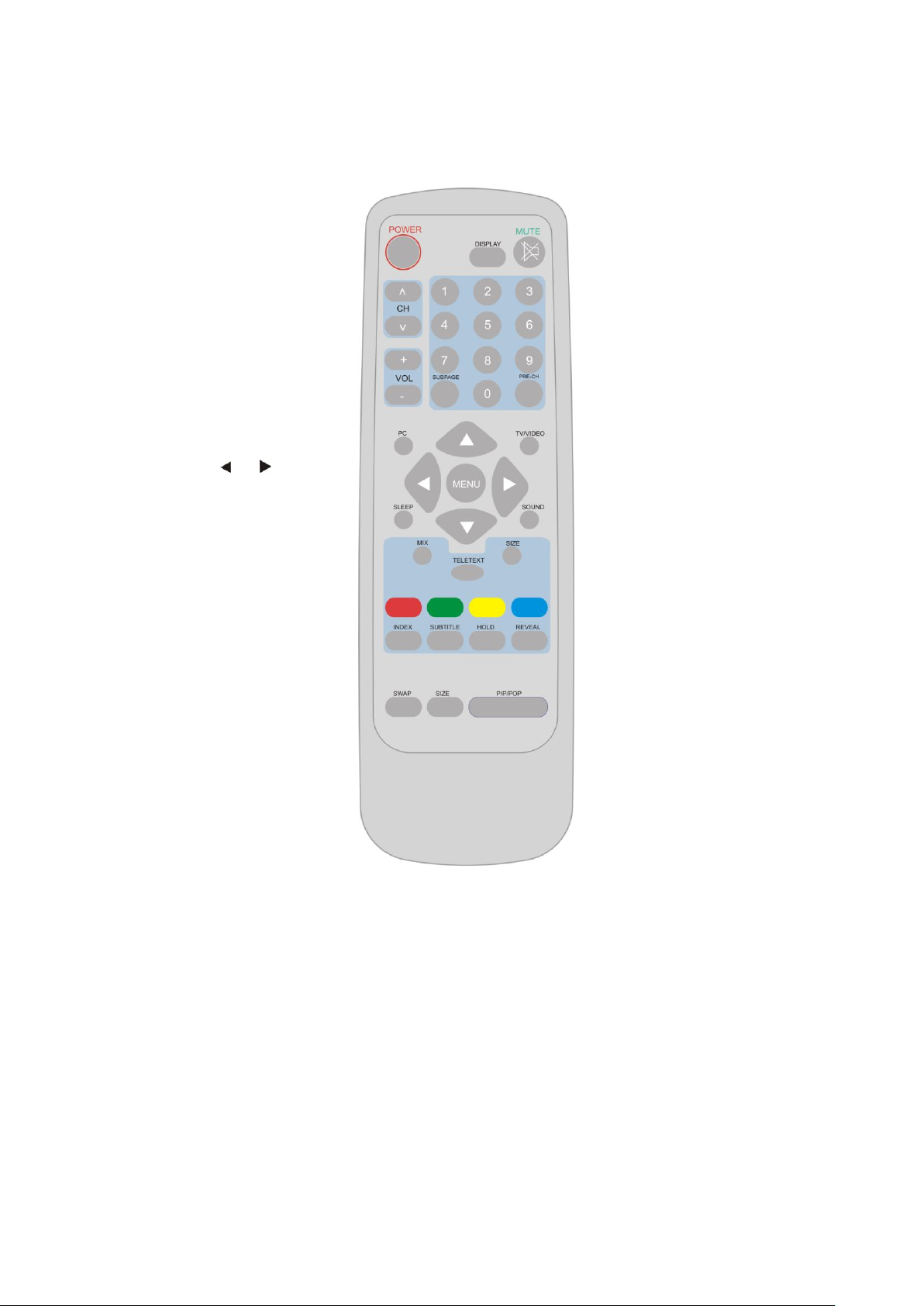
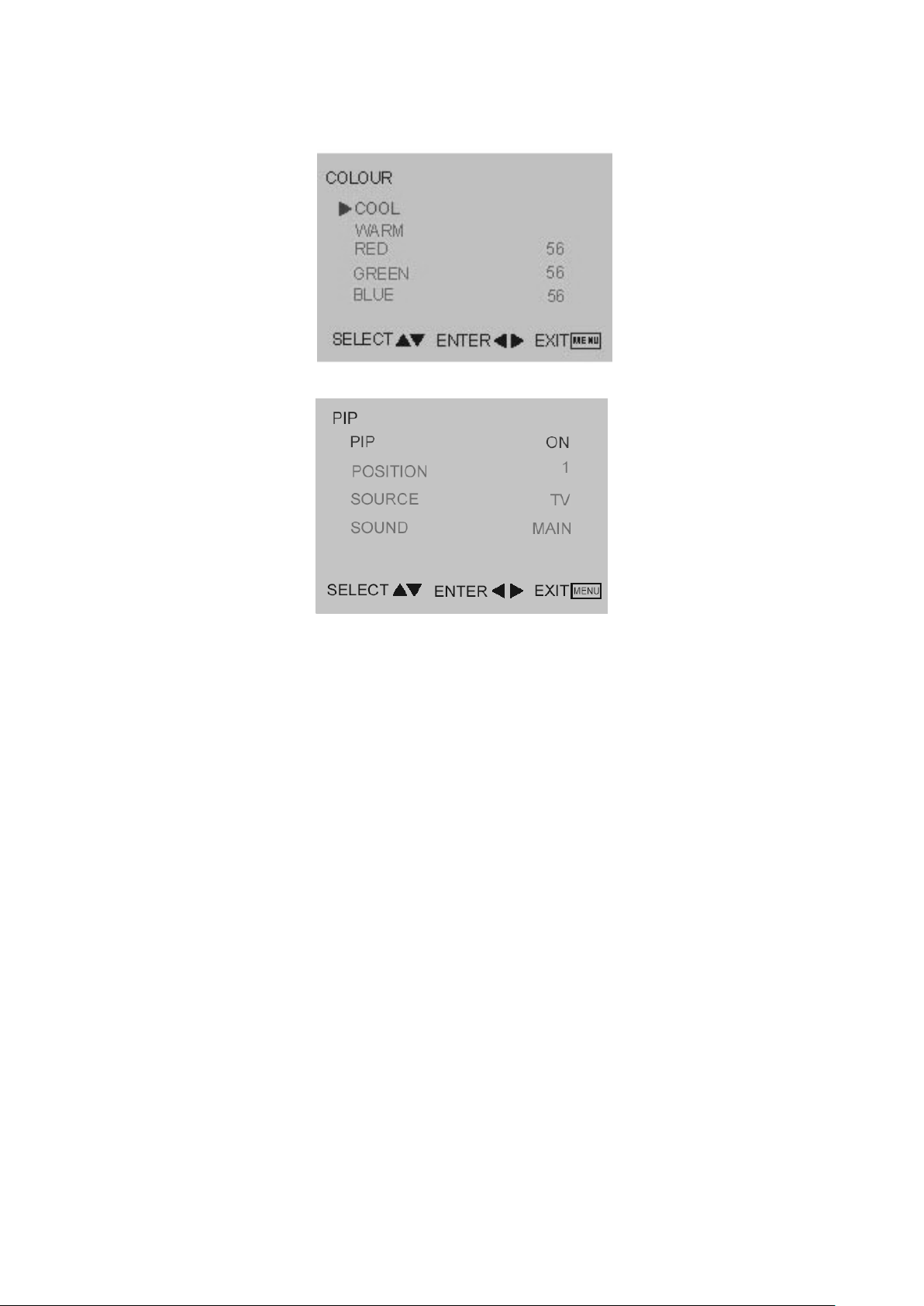
2.2 To Use The Menus
1. Press the MENU button repeatedly to display each menu
2. Use the cursor up/down to select a menu item or adjust the setting of Menu item.
3. Use the cursor left/right to enter a submenu or enable the function.
4. Press the MENU button to exit the menu.
Main Menu
Press the MENU button into the main OSD (On Screen Display). Adjust item include VIDEO, AUDIO, TV (only in
the TV mode), PC and PIP (only in the PC mode) and SETUP.
Video Adjust
1. Contrast, Brightness , COLOUR and TINT are adjusted from 0 to 100.
2. Black Level is adjusted from 0 to 100.
3. Sharpness is adjusted from -5 to+5.
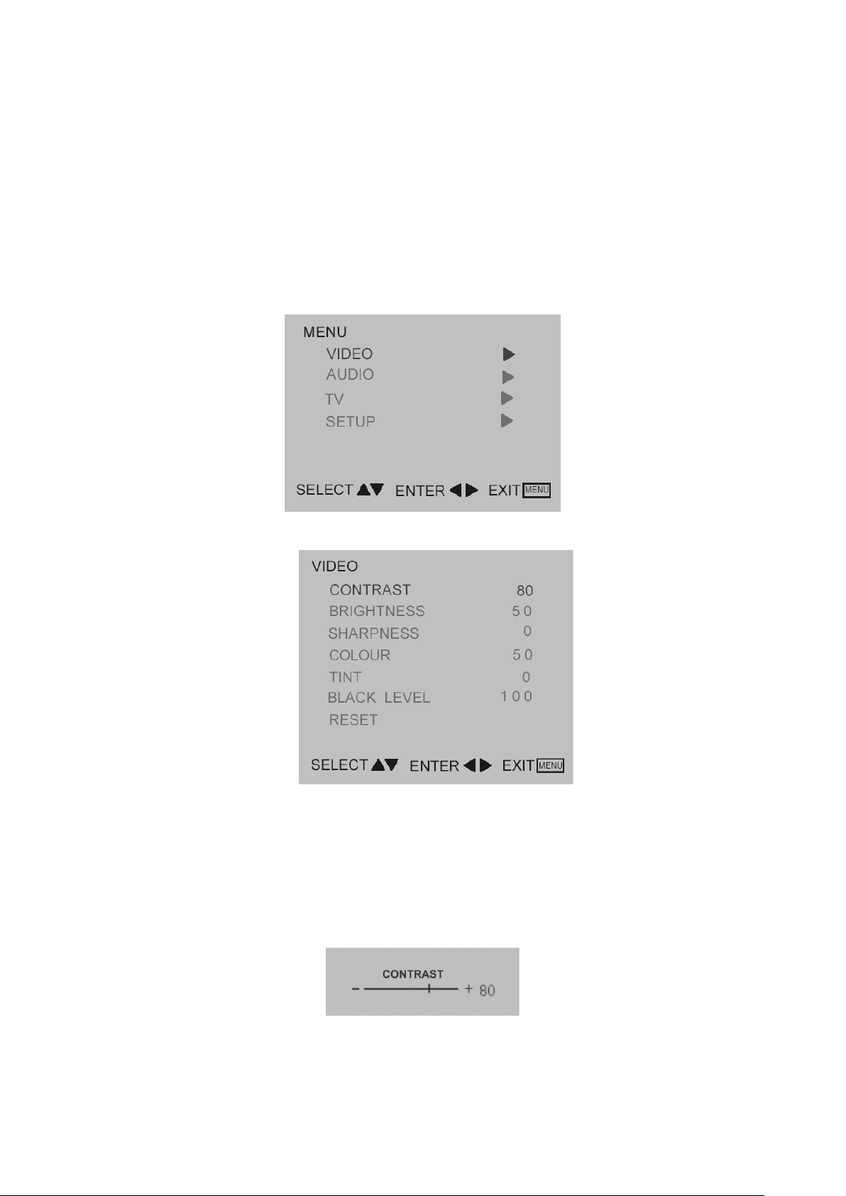
You can adjust picture contrast, brightness, color, tint and sharpness to the levels you prefer.
4. Reset is set up to default value.
Note: TINT only work in NTSC video signal input.
When adjust any item sub-OSD will show up like this.
- -
Page 7

N17XA22-2
7
Audio Adjust
1. Volume is adjusted from 0 to 100.
2. Bass and Treble are adjusted from 0 to 100.
You can adjust picture Volume, Bass and Treble to the levels you prefer.
When adjust any item sub-OSD will show up like this.
3. SRS for turn on / off SRS function. SRS is audio technology makes everything sound better
TV
Quick Installation
1. Use COUNTRY to select your country first.
2. Move to SCAN and scan the program.
3. After scan finished, user can use SKIP to skip the unlike program.
PROGRAM Editing
Using PROGRAM, FREQENCY, SWAP, and INSERT for program edit.
1. Move to PROGRAM, select the program you want to edit
2. Move to FREQENCY, use RIGHT or LEFT button for program search.
3. User can use SWAP for program swap.
4. Use INSERT to insert current program into selected position.
- -
Page 8
N17XA22-2
8
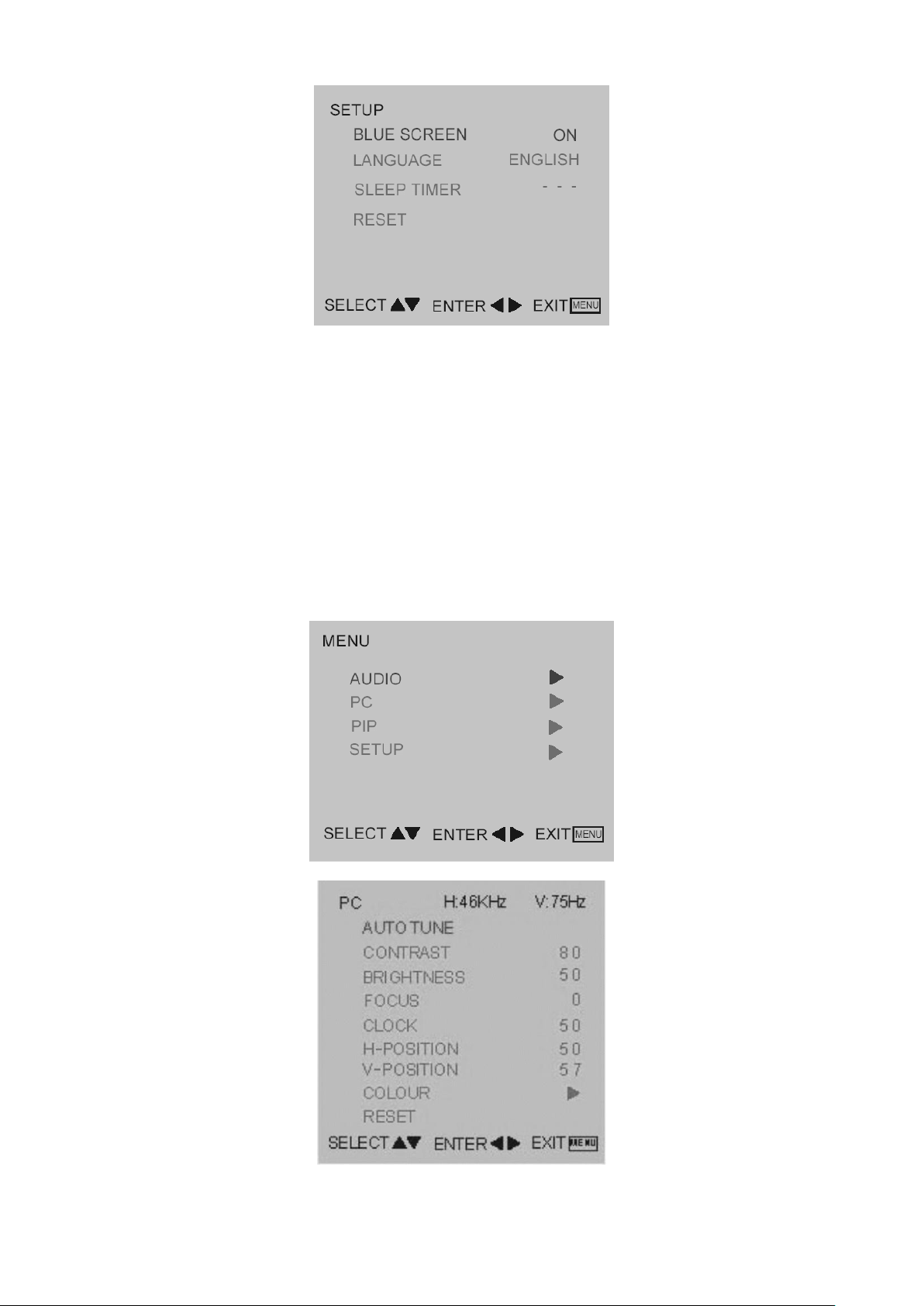
Set up
1. Blue screen: when no video input ,screen will be blue or blank. If it’s ON, the screen will be in blue. If it’s OFF,
the screen will be blank. Preset is ON.
2. Language: For different language OSD MENU. Preset is English.
3. SLEEP TIMER is for set a time period after which the TV should switch itself to standby. The counter runs from
0>30>60>90>120 minutes.
4. Reset is set up to default value of BLUE SCREEN and SLEEP TIMER.
Note: To view the remaining time, press the SLEEP button once. To cancel the sleep time, repeatedly press the
SLEEP button until… APPEARS. If you turn the TV off after setting the sleep time, the setting will be erased. Set it
again.
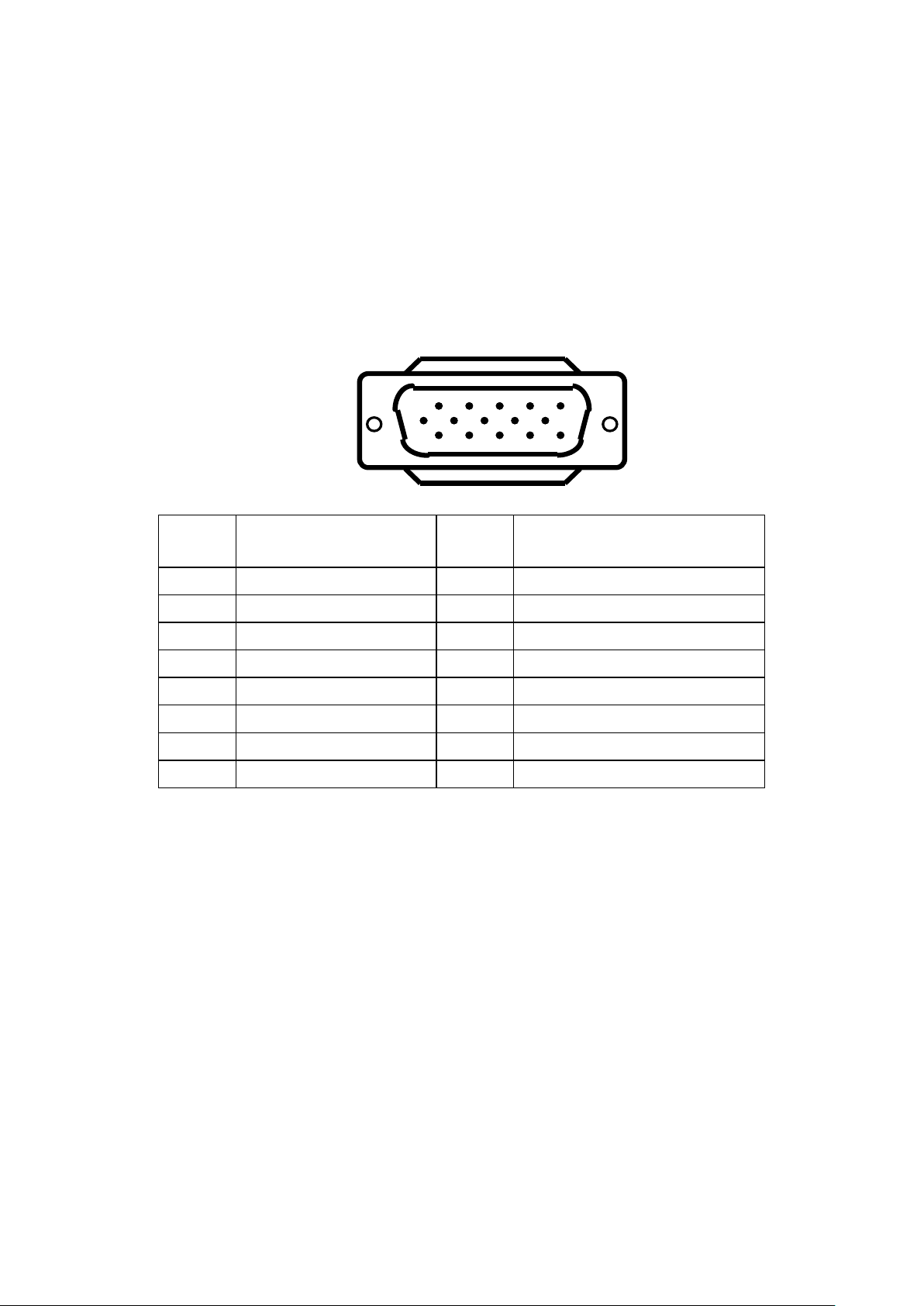
PC Setup
PC Adjust
1. Auto tune is the function auto-sizing for VGA input.
2. Contrast, Brightness, Focus, Clock, H Position, V Position and Color are the functions for PC adjustment.
- -
Page 9
N17XA22-2
9
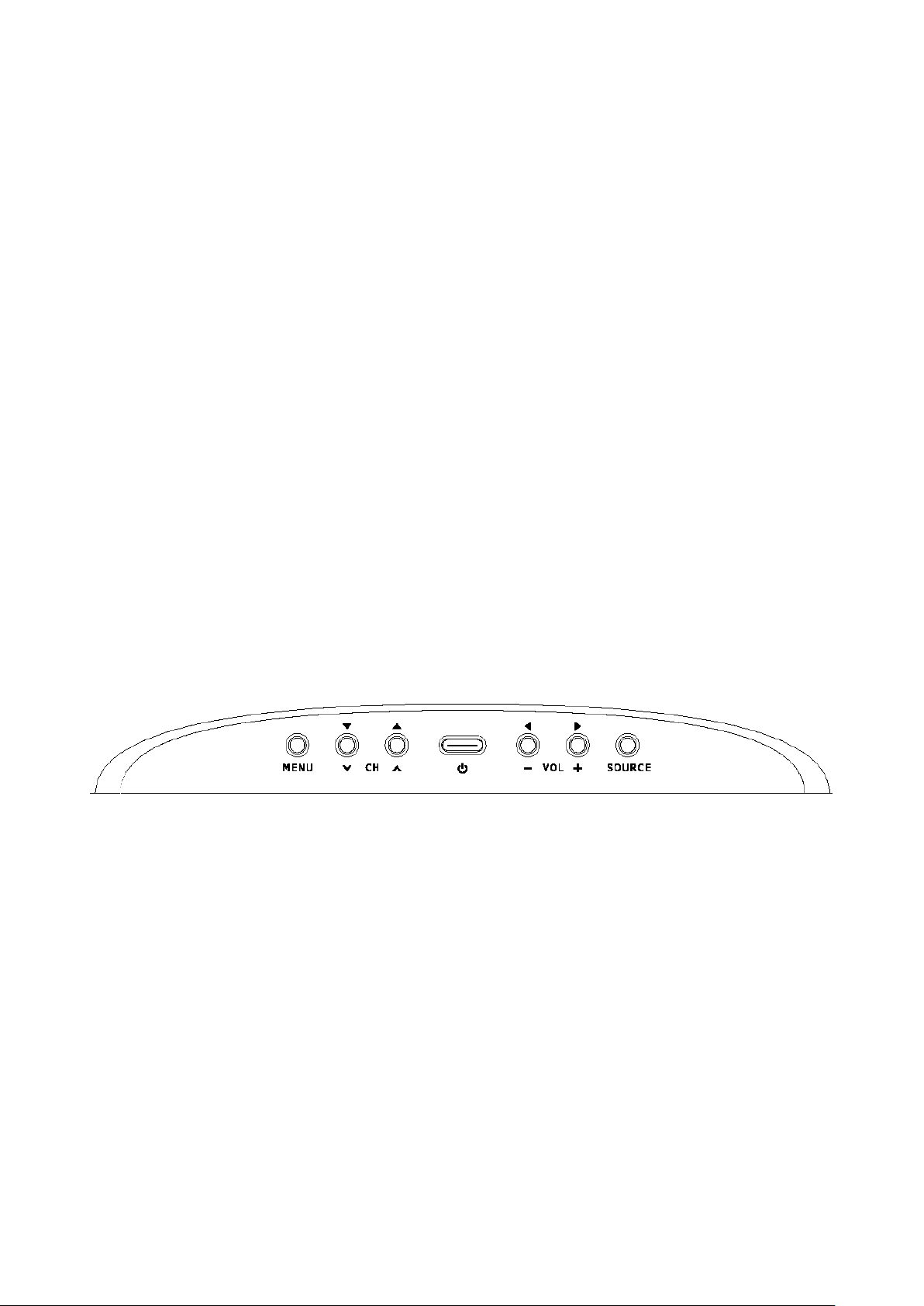
COLOUR
Colour for you can adjust the colour temperature you prefer.
PIP
PIP
1. PIP for turn on / off small picture function.
2. POSITION for change the position of small picture.
3. SOURCE for select video source of small picture.
4. SOUND for select audio source form MAIN (PC) or SUB (Video).
- -
Page 10

N17XA22-2
10
2.3 LCD TV Description
The LCD TV will contain a main board (include audio), a switching power board (include an inverter board),
an IR board, a function keyboard, a headphone Board. The main board and power board will house the flat
panel to control logic I²C bus, DDC, brightness control logic for LCD panel, DC-DC conversion to supply the
appropriate power to the whole board and transmitting TTL level signals into LCD Module to drive the LCD
display circuit.
The inverter board will drive the four CCFLs (Cold Cathode Fluorescent Tube).
The switching power board will provides the power ON/OFF to control the TV and control LED indicator for
DPMS.
The function keyboard and Remote Control will provide the OSD control signal to the Main Board.
2.4 Interface Connector
(A) Power Cord Connector.
(B) RF Signal Connector.
(C) Video / Audio Signal Connectors.
(D) PC D-sub 15 pin Connector.
(E) PC Audio Connector.
- -
Page 11

N17XA22-2
11
3. Precautions and Notices
3.1 Assembly Precaution
(1) Please do not press or scratch LCD panel surface with anything hard. And do not soil LCD panel surface
by touching with bare hands (Polarize film, surface of LCD panel is easy to be flawed)
In the LCD panel, the gap between two glass plates is kept perfectly even to maintain display
characteristic and reliability. If this panel is subject to hard pressing, the following occurs:
(a) Uniform color (b) Orientation of liquid crystal becomes disorder
(2) Please wipe out LCD panel surface with absorbent cotton or soft cloth in case of it being soiled.
(3) Please wipe out drops of adhesive like saliva and water in LCD panel surface immediately.
They might damage to cause panel surface variation and color change.
(4) Do not apply any strong mechanical shock to the LCD panel.
3.2 Operating Precaution
(1) Please be sure to unplug the power cord before remove the back-cover. (Be sure the power button is
turn-off)
(2) Please do not change variable resistance settings in MAIN-BOARD; they are adjusted to the most
suitable value. If they are changed, it might happen LUMINANCE does not satisfy the white balance
spec.
(3) Please consider that LCD backlight takes longer time to become stable of radiation characteristic in low
temperature than in room temperature.
(4) Please pay attention to displaying the same pattern for very long-time. Image might stick on LCD.
3.3 Storage Precaution
(1) When you store LCD for a long time, it is recommended to keep the temperature between 0°C -40°C
without the exposure of sunlight and to keep the humidity less than 85% RH.
(2) Please do not leave the LCD in the environment of high humidity and high temperature such as 60°C,
85%RH.
(3) Please do not leave the LCD in the environment of low temperature: below -25°C.
3.4 High Voltage Warning
The high voltage was only generated by INVERTER module on Power Board, if carelessly contacted the
transformer on this module, can cause a serious shock. (The lamp voltage after stable around 600V, with
lamp current around 8mA, and the lamp starting voltage was around 1500V, at Ta=25°C)
- -
Page 12
N17XA22-2
12
Pin No.
Description
Pin No.
Description
1
Red Video
9
VGA_5V
2
Green Video
10
Sync Ground
3
Blue Video
11
RXD (for ISP)
4
TXD (for ISP)
12
Serial Data for DDC
5
Ground
13
H-Sync.
6
Red Ground
14
V-Sync.
7
Green Ground
15
Serial Clock for DDC
8
Blue Ground
1611
15
5
10
4. D-SUB Pin Distribution
4.1 D-SUB Connector
This procedure gives you instructions for installing and using the LCD TV display.
1. Position the display on the desired operation and plug the power cord into a convenient AC outlet.
Three-wire power cord must be shielded and is provided as a safety precaution as it connects the
chassis and cabinet to the electrical conduct ground. If the AC outlet in your location does not have
provisions for the grounded type plug, the installer should attach the proper adapter to ensure a safe
ground potential.
2. Connect the 15-pin color display shielded signal cable to your signal system device and lock both
screws on the connector to ensure firm grounding. The connector information is as follow:
15 - Pin Color Display Signal Cable
3. S-Video ( Y /C ): TV rear side : 4 pin Mini-DIN female
Component Video: TV rear side : RCA female ( Red / Blue / Green )
TV: TV rear side : IEC type female
AV1,AV2 : TV rear side : RCA female (Yellow )
Audio: TV rear side : RCA female (Red / White )
PC Input audio: 3.5mm Stereo female
Audio Input for AV1,AV2,S-Video, Component Video : RCA female ( Red / White )
Headphone 3.5mm female
Audio line Out ( to another speaker ) : RCA female ( Red / White )
4. Apply power to the display by turning the power switch to the "ON" position and allow about ten seconds
for Panel warm-up. The Power-On indicator lights "GREEN" when the display is on.
5. With proper signals feed to the display, a pattern or data should appear on the screen, adjust the
brightness and contrast to the most pleasing display, or press auto-adjust to get the best picture-quality.
6. This TV (with PC function) has power saving function following the VESA DPMS. Be sure to connect the
signal cable to the PC.
7. If your TV requires service, it must be returned with the power cord.
- -
Page 13

N17XA22-2
13
VESA MODES
Horizontal
Vertical
Mode
Resolution
Nominal
Frequency
(KHz)
Sync
Polarity
Nominal
Freq.
(Hz)
Sync
Polarity
DOS
720x400@70Hz
31.5
N
70.1
N
VGA
640x480@60Hz
31.469
N
59.940
N
640x480@72Hz
37.861
N
72.809
N
640x480@75Hz
37.500
N
75.00
N
SVGA
800x600@60Hz
37.879
P
60.317
P
800x600@72Hz
48.077
P
72.188
P
800x600@75Hz
46.875
P
75.000
P
1024 x768@60Hz
48.360
P
60.000
P
4.2 Factory Preset Display Modes:
Analog RGB Signal Timing
- -
Page 14
N17XA22-2
14
5. Adjustment
5.1 Adjustment Control Function
Adjustments items as below:
5.1.1 Power On / Off.
5.1.2 PC
Auto adjustment for Brightness, Contrast, Pixel Clock Frequency, Focus,
Picture H / V Position and Color Temperature.
Recall Cool, Warn and User color adjust for Color Temperature.
5.1.3 PIP
Position Select, Video source select, Audio main/sub Select.
5.1.4 TV
Channel Up / Down, Channel Search, Volume Bass / Treble adjusts.
Blue screen / Language / System / CH swap /Manual scan / CH Del Add
Reset.
5.1.5 Video
Brightness and Contrast adjust, Saturation adjust,
Sharpness and Black level adjust, reset
5.2 Front Panel Control Knobs
Power Key: Press to turn on or off the TV.
MENU Key: Press to show the OSD menu and exit OSD menu at the TV.
Down/Up Key: Press to perform select function and channel.
-/+ Key : Press to confirm your function selection and adjustment.
Source Key : Press to select your input source.
- -
Page 15
N17XA22-2
15
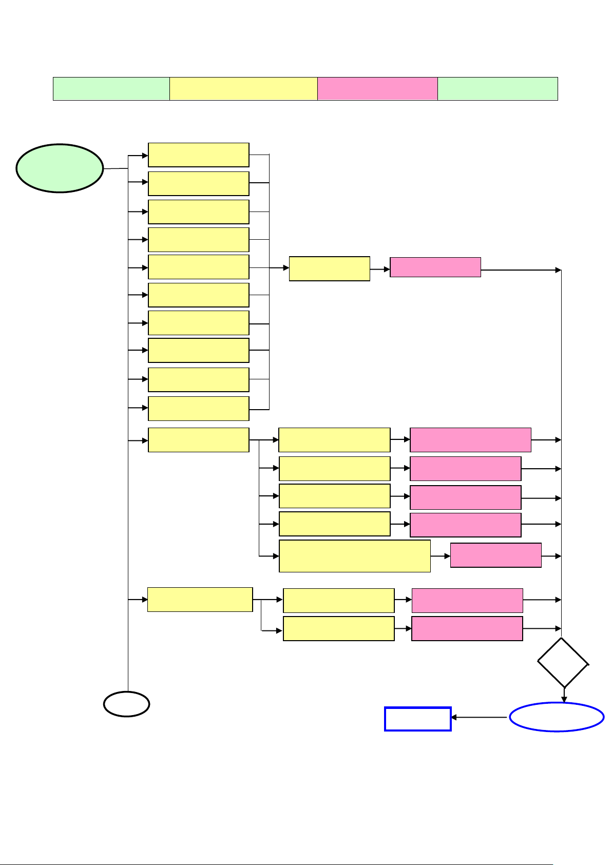
Defect Mode
Failure Analysis
Repair
Testing
Completed
NG
Next Step
Missing Line
Bright Dot
Dark Dot
Light Leakage
Mura
Image Sticking
Dot Defect
Brightness Spot
Dot Defect
Particle
Check Panel
Panel Change
No display
Check Power Board
Check Main board
Check Panel
Change Panel
Change Main board
Change Power Board
Check Keyboard
Change Keyboard
Check Line Connected
Power board and Minored
Change Wires
Noise
Check Main board
Check Panel
Change Main board
Change Panel
A
Abnormal
Display
Test
6. Repair Flow Chart
- -
Page 16
N17XA22-2
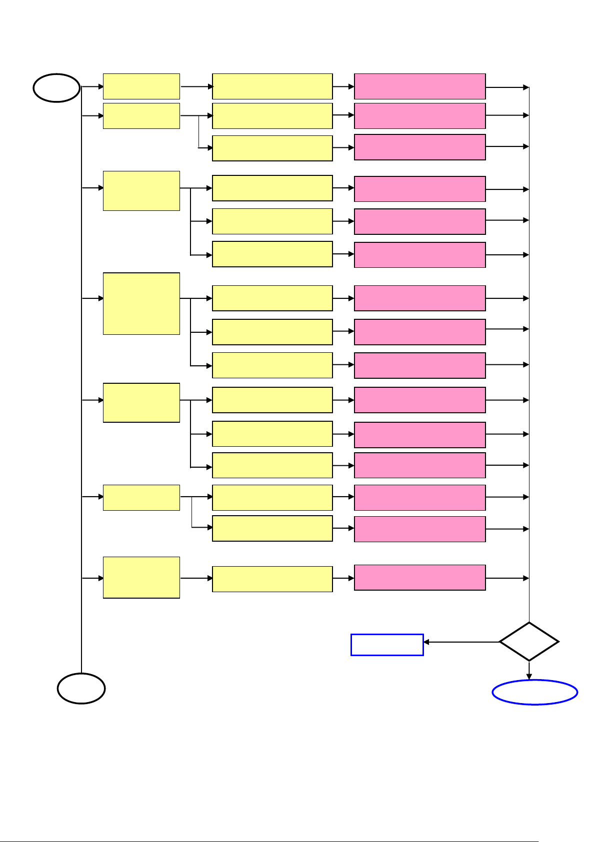
16
Test
Complete
A
A
Noise
Check Single Cable
Change Single Cable
Flicker
Check Main board
Change Main board
Check Panel
Change Panel
Abnormal
Gray
Check Main board
Change Main board
Check Panel
Change Panel
Check LVD Cable
Change LVDS Cable
R\G\B
Display
Abnormal
Check Single Cable
Change Single Cable
Check Main board
Change Main board
Check Panel
Change Panel
Monitor
Shut Down
Check Power board
Change Power board
Check Keyboard
Change Keyboard
Check Main board
Change Main board
No signal
Check Single Cable
Change Single Cable
Check Main board
Change Main board
Power on
Display
Abnormal
Check Main board
Change Main board
Next
- -
Page 17
N17XA22-2
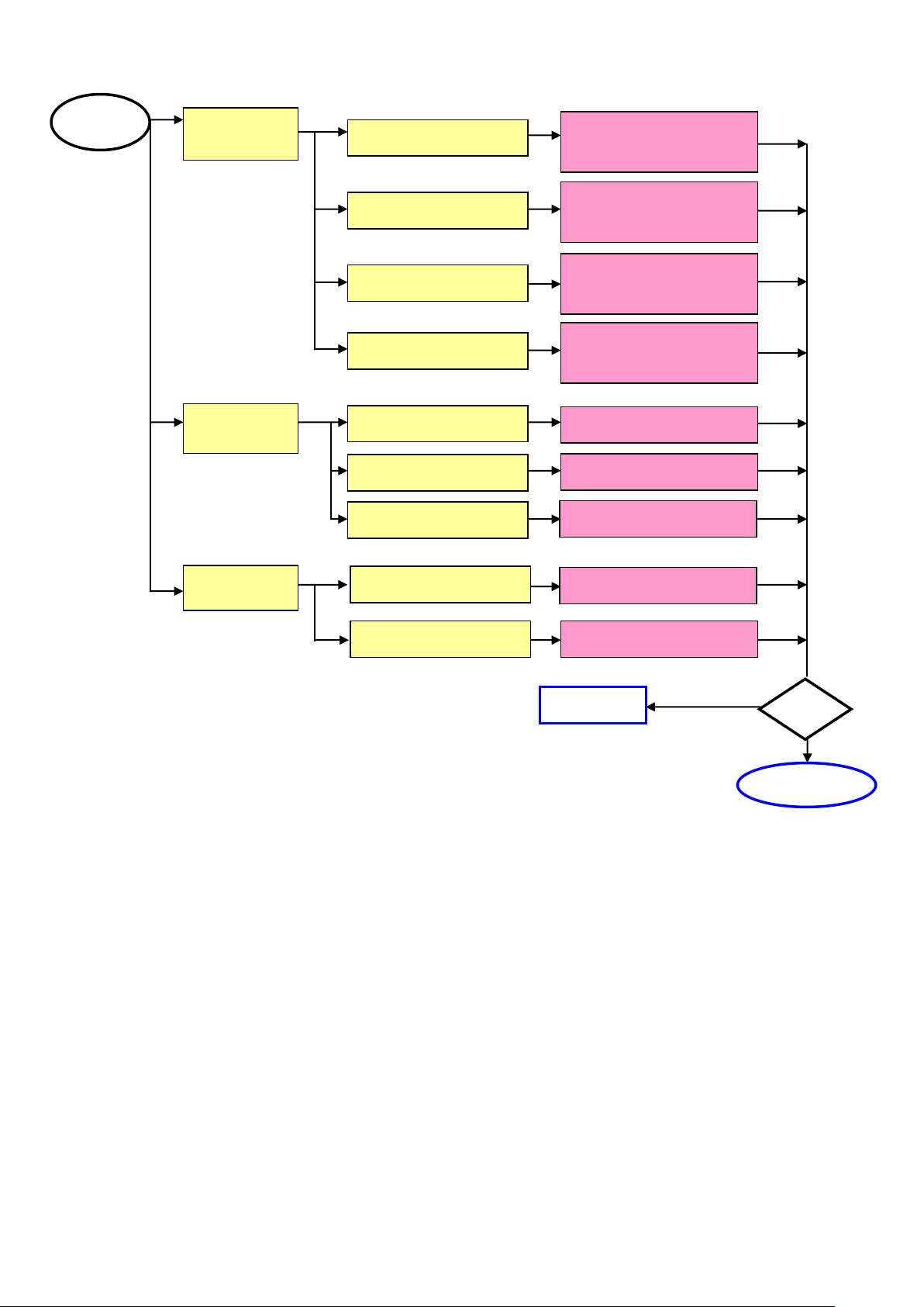
17
Change Keyboard or
Main board
Change Keyboard or
Main board or wire
Change Keyboard
Change Main board
Change Main board
Change LVDS Wire
LED Off
Change Keyboard or
Main board or wire
Change Keyboard or
Main board or wire
A
Change Wires
LED Abnormal
LED Dark
LED Display
Abnormal
LED Flicker
Abnormal
Keyboard
Check Wires
Check Keyboard
Check Main board
Abnormal
OSD
Check Main board
Check LVDS Wire
Test
Next step
Complete
- -
Page 18
N17XA22-2
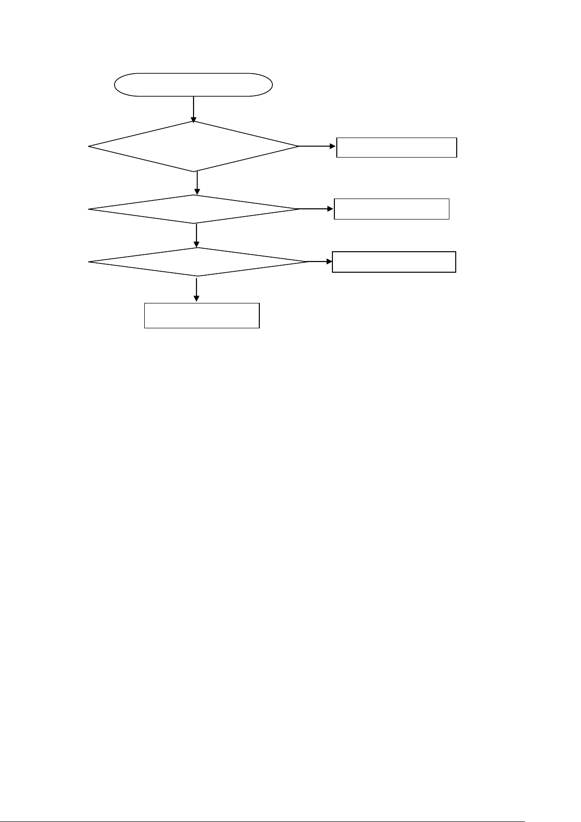
18
OSD is unstable or not working
Is Key Pad Board connecting normally?
Connect Key Pad Board
Is Button Switch normally?
Replace Button Switch
Y
N
N
Is Key Pad Board Normally?
Replace Key Pad Board
Y N Y
Check Main Board
Key Board
- -
Page 19

N17XA22-2
19
Color Temp.
PC 7800K
PC 6500K
AV 7800K
X
0.296
0.313
0.296
Y
0.311
0.329
0.311
Y
250±7
250±7
250±7
7. White-Balance, Luminance adjustment
Approximately 30 minutes should be allowed for warm up before proceeding white balance adjustment.
Before started adjust white balance, please setting the Chroma-7120 MEM. Channel 1 to PC 7800K colors,
MEM. Channel 2 to PC 6500K color, and MEM. Channel 3 to AV 7800 colors, (PC 7800 parameter is
x = 296 ± 15, y = 311 ± 15, Y = 250 ± 7 cd/m2; PC 6500K parameter is x = 313 ± 15, y = 329 ± 15,
Y = 250± 7 cd/m2 ; AV 7800K parameter is x = 296 ± 15, y = 311 ± 15,Y = 250± 7 cd/m2)
How to setting MEM. channel you can reference to Chroma-7120 user guide or simple use “ SC” key and
“ NEXT” key to modify x, y, Y value and use “ID” key to modify the TEXT description
Following is the procedure to do white-balance adjust
˙Press Number key 100 9 9 9 will into the factory mode, and press Menu key the OSD will show menu
and a word F at Right top of Menu.
˙In the factory mode select MORE function will into Bias and Gain adjustment.
1. ADC Adjustment:
AL Auto level adjust.
RG, GG, BG R, G, B Gain adjusts.
RB, GB, BB R, G, B Bias adjusts.
2. SCALER Adjustment:
CO, BR Contrast and Brightness adjust.
RG, GG, BG R, G, B Gain adjusts.
RB, GB, BB R, G, B Bias adjusts.
S9, S6, ST, SH Save 9300, 6500, 9300 color temperature.
R9, R6, RT, RH Recall 9300, 6500, 9300-color temperature.
BI Setup Burn-in mode ON / OFF.
ISP Set ISP ON/OFF.
PP Set PIP ON/OFF.
WH Set Wireless Headphone ON/OFF.
SR Set SRS ON/OFF.
CC Set Close Caption ON/OFF.
VC Set V Chip ON/OFF.
EX Exit MORE function to factory mode menu.
II. Bias (Low luminance) adjustment:
1. Press “ AUTO” button,
2. Set the contrast on OSD window to the value=51, color (user) R, G, B set to “50”
3. Adjust the brightness on OSD until chroma 7120 measurement reach the value Y>350 cd/m2
III. Gain adjustment:
A. Adjust PC 7800K color-temperature:
1. Set the Contrast of OSD function to 45 and Adjust Brightness to chroma-7120 Y>390 cd/m2
2. Switch the chroma-7120 to RGB-mode (with press “MODE” button)
3. Switch the MEM. channel to Channel 01 (with up or down arrow on chroma-7120)
4. The LCD-indicator on chroma-7120 will show x = 296 ± 15, y = 311 ± 15, Y = 250 ± 7 cd/m2
5. Adjust the Color(user)Mode: RED on OSD window, until chroma 7120 indicator reached the value R=100
6. Adjust the Color (user) Mode: GREEN on OSD window, until chroma-7120 indicator reached the value
G=100
7. Adjust the Color (user) Mode: BLUE on OSD window, until chroma-7120 indicator reached the value
B=100
8. Repeat above procedure (Item 5,6,7) until chroma-7120 RGB value meet the tolerance =100±2
9. switch the chroma-7120 to xyY mode With press “MODE” button
10. Press Color (9300) on OSD window to save the adjustment result
- -
Page 20

N17XA22-2
20
B. Adjust PC 6500K color-temperature:
1. Set the Contrast of OSD function to 45 and Adjust Brightness to chroma-7120 Y>390 cd/m2
2. Switch the chroma-7120 to RGB-mode (with press “MODE” button)
3. Switch the MEM. channel to Channel 02 (with up or down arrow on chroma-7120)
4. The LCD-indicator on chroma-7120 will show x = 313 ± 15, y = 329 ± 15, Y = 250 ± 7 cd/m2
5. Adjust the Color (user) Mode: RED on OSD window, until chroma 7120 indicator reached the value R=100
6. Adjust the Color (user) Mode: GREEN on OSD window, until chroma-7120 indicator reached the value
G=100
7. Adjust the Color (user) Mode: BLUE on OSD window, until chroma-7120 indicator reached the value B=100
8. Repeat above procedure (item 5,6,7) until chroma-7120 RGB value meet the tolerance =100 ± 2
9. Switch the chroma-7120 to xyY mode with press “MODE” button
10.Press Color (6500) on OSD window to save the adjustment result
C. Adjust AV 7800K color-temperature:
1. Set the Contrast of OSD function to 45 and Adjust Brightness to chroma-7120 Y>250 cd/m2
2. Switch the chroma-7120 to RGB-mode (with press “MODE” button)
3. Switch the MEM. channel to Channel 03 (with up or down arrow on chroma-7120)
4. The LCD-indicator on chroma-7120 will show x = 296 ± 15, y = 311 ± 15, Y = 250 ± 7 cd/m2
5. Adjust the Color (user) Mode: RED on OSD window, until chroma 7120 indicator reached the value R=100
6. Adjust the Color (user) Mode: GREEN on OSD window, until chroma-7120 indicator reached the value
G=100
7. Adjust the Color (user) Mode: BLUE on OSD window, until chroma-7120 indicator reached the value B=100
8. Repeat above procedure (item 5,6,7) until chroma-7120 RGB value meet the tolerance =100 ± 2
9. Switch the chroma-7120 to xyY mode with press “MODE” button
10. Press Color (9300) on OSD window to save the adjustment result
Turn the POWER-button off to on to quit from factory mode (in USER-mode, the OSD window location was
placed at middle of screen)
- -
Page 21

N17XA22-2
21
Location
Part No. for TPV
Description
Quantity
Unit
PWTV1742FJB2
POWER BOARD
1
PCS
M1V1130 6128
SCREW
4
PCS
M1V1130 6128
SCREW
5
PCS
CBPF764BFSA3
CONVERSION BOARD
1
PCS
11V6043 1
SPACER
1
PCS
15V5928 14
MAIN FRAME
1
PCS
15V5930 3
BKT CONNECTOR
1
PCS
15V8024 1
BRACKET MAIN
1
PCS
26T 800504 8
BARCODE
1
PCS
34V1205 GM L
COVER CABLE
1
PCS
34V1206 GN 3L
COVER HINGE
1
PCS
33V4657 GN L
COVER STAND F
1
PCS
34V1208 GN L
STAND
1
PCS
34V1209 GN L
COVER STAND B
1
PCS
37V 479 1
HINGE
1
PCS
Q1V 130 12120
SCREW 3MMX12
4
PCS
Q1V 330 8120
SCREW 3X8mm
3
PCS
Q1V 330 12120
SCREW 3X12mm
1
PCS
40T 170624 4B
ID LABEL
1
PCS
40T 583 13
I/O LABEL
1
PCS
41T2001624 1B
MANUAL
1
PCS
41T780062414C
QSG 1 PCS
44T1702 1
EPS 1 PCS
44T1702 2
EPS 1 PCS
44T3231 15
EVA WASHER
2
PCS
44T3719600 1A
CARTON
1
PCS
45T 76 28 RN
PE BAG FOR MANUAL
1
PCS
45T 76 34 RN
PE BAG FOR BASE
1.05
PCS
45T 88609 7
EPE COVER
1
PCS
45T 88626 4
PE BAG FOR MONITOR
1.05
PCS
50T 500 1
CABLE TIE
2
PCS
52T 1150 C
WHITE TAPE
80
CM
52T 1185
MIDDLE TAPE FOR CARTON
50
CM
52T 1186
SMALL TAPE
10
CM
52T 1205 A
ALUMINIUM TAPE
2
PCS
52T 1208 A
ALUMINIUM TAPE
6
PCS
52T 1211 A
ADHESIVE TYPE
3
PCS
52T 1211516
ALUMINUM TAPE
2
PCS
52T6020 7
PROTECT FILM
1
PCS
52T6025 11690
INSULATE SHEET
1
PCS
85V 653 1
SHIELD CONNETDR
1.1
PCS
85V 665 4
SHELD
1
PCS
89T 173 56 22
PHONE PLUG
1
PCS
89T404A18N IS
POWER CORD
1
PCS
92TB1JX1A31GF
BATTERY
2
PCS
95T8014 8 15
HARNESS 8P-4P+4P 400mm
1
PCS
95T8018 20513
HARNESS 20P-20P 160mm
1
PCS
98TR7SW7NT F
Remote Control
1
PCS
M1V 140 10120
SCREW M4X10
4.2
PCS
8. Parts List of Cabinet
E764FSNBA2N22M
- -
Page 22

N17XA22-2
22
M1V 330 4128
SCREW M3X4
2
PCS
M1V 330 4128
SCREW M3X4
2.35
PCS
M1V 330 4128
SCREW M3X4
2
PCS
M1V 330 4128
SCREW M3X4
1
PCS
M1V 330 6128
SCREW
1
PCS
M1V 330 6128
SCREW
1.1
PCS
M1V 340 10120
SCREW
4.2
PCS
M1V1130 6128
SCREW
1.5
PCS
M1V1140 4128
SCREW 4X6
1.05
PCS
Q1V 330 12120
SCREW 3X12mm
5.25
PCS
Q1V 930 6128
SCREW (T3X6)
2.1
PCS
Q1V1030 12128
SCREW
7.35
PCS
705L764FB34S01
ASS'Y
1
PCS
750VVF70W02
FUJITCU 17" PANEL
1
PCS
E089B
89T1738GAA D1
SIGNAL CABLE
1
PCS
705L764FB34S01
12T 394 3
RUBBER FOOT
9
PCS
15V5932 1
BKT BASE
1
PCS
Q1V 130 8120
SCREW
10
PCS
T34T1375 GN L
BASE-S2
1
PCS
PWTV1742FJB2
PW1742FJB2SMT
POWER BOARD FOR SMT
1
PCS
40T 45762420A
S/N LABEL
1.03
PCS
52T 1174
TYPE
12
CM
705L 20 93 16
D910/D911 ASS'Y
1
PCS
705L 780 87 20
CN901 ASS'Y
1
PCS
705L780K 57 03
Q901 ASS'Y
1
PCS
BD901
93T 50460 16
U4KB80R
1
PCS
C101
67T215H102 3N
KY16VB1000M-L 10*20
1
PCS
C108
67T215L471 3N GP
105尼んLOWESR 470UF +
1
PCS
C110
67T215L471 3N GP
105尼んLOWESR 470UF +
1
PCS
C201
67T 2154714NT
KY25VB470M-TP5 8*20
1
PCS
C204
65V 3J1206ET
12PF 5% SL 3KV TDK
1
PCS
C205
65V 3J1206ET
12PF 5% SL 3KV TDK
1
PCS
C225
67T 2154714NT
KY25VB470M-TP5 8*20
1
PCS
C236
65V 3J1206ET
12PF 5% SL 3KV TDK
1
PCS
C237
65V 3J1206ET
12PF 5% SL 3KV TDK
1
PCS
C901
65T306M1022BM
Y1.CAP.001UF 250VAC MUR
1
PCS
C902
65T306M1022BM
Y1.CAP.001UF 250VAC MUR
1
PCS
C905
67T215S10115N GP
EC CAP 450V/100
1
PCS
C914
67T215L102 4N GP
KY25VB1000M-L 12.5*20
1
PCS
C915
67T215L222 4N
KY25VB2200M-L 12.5*35
1
PCS
C916
67T 2154714NT
KY25VB470M-TP5 8*20
1
PCS
C921
65T306M4722BP
4700PF +-20% 400VAC
1
PCS
C922
67T 2154797NT GP
KY, 4.7UF +-20% 50V 105
1
PCS
C923
65T306M1022BM
Y1.CAP.001UF 250VAC MUR
1
PCS
CN201
33T8020 4D U
WAFER
1
PCS
CN202
33T8020 4D U
WAFER
1
PCS
CN902A
73G 174 61 L
CHOKE
1
PCS
CN902B
73G 174 61 L
CHOKE
1
PCS
CN903
33T800910Q H
PIN HEADER 1*10P R/A
1
PCS
IC902
56T 139 3A
PC123Y22FZOF
1
PCS
L101
73T 253151 T
CHOKE COIL
1
PCS
- -
Page 23

N17XA22-2
23
L902
73G 174 60 LH
LINEFIL TER BY LITAI
1
PCS
L903
73T 253 91 LS
CHOKE BY LI SHIN
1
PCS
L904
73L 174 40LSG
LINE FILTER
1
PCS
NR901
61T 5810T
8 OHM 4A NTCR BY THINKI
1
PCS
P051
51T 6 4502
RTV 2 G
PT201
80LL17T 17DNG
LH-10 DARFON
1
PCS
PT202
80LL17T 17DNG
LH-10 DARFON
1
PCS
PT203
80LL17T 17DNG
LH-10 DARFON
1
PCS
PT204
80LL17T 17DNG
LH-10 DARFON
1
PCS
R903
61T152M10458F6267
100K OHM 5% 2W
1
PCS
R914
61T152M278 64
0.27 OHM 5% 2W
1
PCS
T901
80LL17T 19 TG
X'FMR
1
PCS
PW1742FJB2AI
POWER BOARD FOR AI
1
PCS
C102
65T0805104 32
CHIP 0.1U 50V X7R
1
PCS
C103
61V0805000
CHIP 0OHM 1/10W
1
PCS
C104
65T0805104 32
CHIP 0.1U 50V X7R
1
PCS
C109
65T0805104 32
CHIP 0.1U 50V X7R
1
PCS
C114
65T0805104 32
CHIP 0.1U 50V X7R
1
PCS
C115
65T0805104 32
CHIP 0.1U 50V X7R
1
PCS
C202
65T0805104 32
CHIP 0.1U 50V X7R
1
PCS
C203
65T1206225 17
1206 2.2UF -20%~+80% 16
1
PCS
C206
65T1206225 17
1206 2.2UF -20%~+80% 16
1
PCS
C207
65T1206225 17
1206 2.2UF -20%~+80% 16
1
PCS
C210
65T0805104 32
CHIP 0.1U 50V X7R
1
PCS
C211
65T0805105 27
CHIP 1UF 25V Y5V 0805
1
PCS
C212
65T0805104 27
CHIP CAP 1UF 25V Y5V
1
PCS
C213
65T0805105 27
CHIP 1UF 25V Y5V 0805
1
PCS
C214
65T0805473 22
SMD 47nf +-10%25V XTR
1
PCS
C217
65T0805104 22
0.1UF +-10% 25V X7R 080
1
PCS
C219
65T0805105 22
CHIP 1UF 25V X7R 0805
1
PCS
C220
65T0805221 21
220PF 25V 5%
1
PCS
C221
65T0805473 22
SMD 47nf +-10%25V XTR
1
PCS
C222
65T0805225 27
2.2UF 1 PCS
C224
65T0805472 22
CHIP 0.0047UF 25V X7R 0
1
PCS
C226
65T0805105 22
CHIP 1UF 25V X7R 0805
1
PCS
C227
65T0805104 22
0.1UF +-10% 25V X7R 080
1
PCS
C228
65T0805682 22
0805 6800PF +-10% 25V X
1
PCS
C229
65T0805104 32
CHIP 0.1U 50V X7R
1
PCS
C230
65T0805473 22
SMD 47nf +-10%25V XTR
1
PCS
C231
65T1206225 17
1206 2.2UF -20%~+80% 16
1
PCS
C232
65T0805152 22
CHIP 0.005UF 25V X7R 08
1
PCS
C233
65T1206225 17
1206 2.2UF -20%~+80% 16
1
PCS
C234
65T1206225 17
1206 2.2UF -20%~+80% 16
1
PCS
C235
65T0805104 32
CHIP 0.1U 50V X7R
1
PCS
C240
65T0805104 22
0.1UF +-10% 25V X7R 080
1
PCS
C243
65T0805104 22
0.1UF +-10% 25V X7R 080
1
PCS
C244
65T0805104 32
CHIP 0.1U 50V X7R
1
PCS
C245
65T0805104 22
0.1UF +-10% 25V X7R 080
1
PCS
C246
65T0805104 22
0.1UF +-10% 25V X7R 080
1
PCS
C247
65T0805104 22
0.1UF +-10% 25V X7R 080
1
PCS
C908
65T0805104 32
CHIP 0.1U 50V X7R
1
PCS
C910
65T0805102 31
1000PF 50V NPO
1
PCS
C911
65T0805104 32
CHIP 0.1U 50V X7R
1
PCS
C912
65T0805104 32
CHIP 0.1U 50V X7R
1
PCS
- -
Page 24

N17XA22-2
24
C913
65T1206102 72
CHIP 1000PF 500V X7R
1
PCS
C917
65T0805104 32
CHIP 0.1U 50V X7R
1
PCS
C918
65T0805104 32
CHIP 0.1U 50V X7R
1
PCS
C924
65T0805104 32
CHIP 0.1U 50V X7R
1
PCS
D101
93T3004 2
SR34 PAN JIT
1
PCS
D201
93T 6433P
BAV99
1
PCS
D202
93T 6433P
BAV99
1
PCS
D203
93T 6433P
BAV99
1
PCS
D204
93T 6433P
BAV99
1
PCS
D206
93T 6433P
BAV99
1
PCS
D207
93T 6433P
BAV99
1
PCS
D208
93T 6432V
LL4148-GSO8 SMD BY VISH
1
PCS
D209
93T 6433P
BAV99
1
PCS
D210
93T 6433P
BAV99
1
PCS
D211
93T 6433P
BAV99
1
PCS
D212
93T 6433P
BAV99
1
PCS
D903
93T 6432V
LL4148-GSO8 SMD BY VISH
1
PCS
D905
93T 6432V
LL4148-GSO8 SMD BY VISH
1
PCS
F902
61V1206000 7
7A 0 OHM
1
PCS
IC101
56T 379 37
FP5001DR-LR
1
PCS
IC201
56T 608 6
02 960G SOP20
1
PCS
IC901
56T 379 33
SG6841SZ
1
PCS
Q101
57T 763 3
AO4411L SO-8 BY AOS SMT
1
PCS
Q102
57T 417 4
CHIP PMBS3904 BY PHILIP
1
PCS
Q103
57T 417 6
PMBS3906/PHILIPS-SMT
1
PCS
Q201
57T 759 2
RK7002
1
PCS
Q202
57T 759 2
RK7002
1
PCS
Q203
57T 417 6
PMBS3906/PHILIPS-SMT
1
PCS
Q204
57T 600 40
MOSFET
1
PCS
Q205
57T 760 4
DTA144WKA BY ROHM SMT
1
PCS
Q206
57T 417 4
CHIP PMBS3904 BY PHILIP
1
PCS
Q207
57T 760 5
DTC144WKA BY FOHM SMT
1
PCS
Q208
57T 600 40
MOSFET
1
PCS
Q209
57T 600 40
MOSFET
1
PCS
Q210
57T 600 40
MOSFET
1
PCS
Q211
57T 759 2
RK7002
1
PCS
Q212
57T 759 2
RK7002
1
PCS
Q213
57T 759 2
RK7002
1
PCS
Q214
57T 759 2
RK7002
1
PCS
Q215
57T 759 2
RK7002
1
PCS
Q902
57T 417 4
CHIP PMBS3904 BY PHILIP
1
PCS
Q903
57T 417 6
PMBS3906/PHILIPS-SMT
1
PCS
R106
61V0603333
CHIP 33K OHM 1/10W
1
PCS
R108
61V0603473
CHIP 47K OHM 1/16W
1
PCS
R109
61V0603300 1F
CHIP 3KOHM 1/16W 1%
1
PCS
R110
61V0603360 1F
CHIP 3.6KOHM 1% 1/10W
1
PCS
R111
61V0805153
CHIPR 15K OHM+-5% 1/8W
1
PCS
R112
61V0805272
CHIP 2.7K OHM 1/8W
1
PCS
R113
61V0603101
CHIPR 100 OHM+-5% 1/10W
1
PCS
R114
61V0603102
CHIPR 1K OHM+-5% 1/10W
1
PCS
R115
61V0603220
CHIPR 22 OHM+-5% 1/10W
1
PCS
R116
61V0603332
CHIP 3.3K OHM 1/10W
1
PCS
R201
61V0805242
CHIP 2.4KOHM 1% 1/8W
1
PCS
R202
61V1206000
CHIP 0 OHM 1/8W
1
PCS
- -
Page 25

N17XA22-2
25
R203
61V0805103
CHIP 10K OHM 1/10W
1
PCS
R204
61V0805103
CHIP 10K OHM 1/10W
1
PCS
R206
61V0805204
200K OHM 1/8W
1
PCS
R207
61V0805103
CHIP 10K OHM 1/10W
1
PCS
R209
61V0805220
CHIP 22 OHM 5% 0805 1/8
1
PCS
R210
61V0805103
CHIP 10K OHM 1/10W
1
PCS
R214
61V0805000
CHIP 0OHM 1/10W
1
PCS
R217
61V0805623
CHIPR 62K OHM +-5% 1/8W
1
PCS
R220
61V0805220
CHIP 22 OHM 5% 0805 1/8
1
PCS
R221
61V0805333
CHIP 33KOHM 1% 1/8W
1
PCS
R222
61V0805513
CHIP 51KOHM 1/8W
1
PCS
R223
61V0805105
CHIP 1M OHM 5% 1/8W
1
PCS
R225
61V0805104
CHIPR 100K OHM+-5% 1/8W
1
PCS
R226
61V0805823
chip 82kohm 1/8w
1
PCS
R227
61V0805103
CHIP 10K OHM 1/10W
1
PCS
R229
61V0805561
CHIP 560 OHM 1/8W
1
PCS
R230
61V0805000
CHIP 0OHM 1/10W
1
PCS
R231
61V0805105
CHIP 1M OHM 5% 1/8W
1
PCS
R235
61V0805000
CHIP 0OHM 1/10W
1
PCS
R237
61V0805124
CHIP 120KOHM 1/8W
1
PCS
R238
61V0805105
CHIP 1M OHM 5% 1/8W
1
PCS
R240
61V0805000
CHIP 0OHM 1/10W
1
PCS
R241
61V0805105
CHIP 1M OHM 5% 1/8W
1
PCS
R242
61V0805000
CHIP 0OHM 1/10W
1
PCS
R243
61V0805105
CHIP 1M OHM 5% 1/8W
1
PCS
R244
61V1206471
CHIP 470OHM 1/8W
1
PCS
R248
61V0805221
CHIPR 220 OHM +-5% 1/8W
1
PCS
R249
61V0805472
CHIRP 4.7K OHM +-5% 1/8
1
PCS
R251
61V0805161
chip 160 ohm 5% 1/8w
1
PCS
R252
61V0805221
CHIPR 220 OHM +-5% 1/8W
1
PCS
R253
61V0805472
CHIRP 4.7K OHM +-5% 1/8
1
PCS
R255
61V0805221
CHIPR 220 OHM +-5% 1/8W
1
PCS
R256
61V0805472
CHIRP 4.7K OHM +-5% 1/8
1
PCS
R258
61V0805161
chip 160 ohm 5% 1/8w
1
PCS
R259
61V0805221
CHIPR 220 OHM +-5% 1/8W
1
PCS
R260
61V0805472
CHIRP 4.7K OHM +-5% 1/8
1
PCS
R262
61V0805124
CHIP 120KOHM 1/8W
1
PCS
R263
61V0805102
CHIPR 1K OHM +-5% 1/8W
1
PCS
R900
61V1206684
CHIP 680K OHM 1/8W
1
PCS
R901
61V1206684
CHIP 680K OHM 1/8W
1
PCS
R902
61V1206684
CHIP 680K OHM 1/8W
1
PCS
R904
61V1206105
CHIP 1MOHM 5% 1/4W
1
PCS
R905
61V1206105
CHIP 1MOHM 5% 1/4W
1
PCS
R906
61V1206105
CHIP 1MOHM 5% 1/4W
1
PCS
R907
61V1206105
CHIP 1MOHM 5% 1/4W
1
PCS
R908
61V1206339
CHIP 3.3OHM 1/4W
1
PCS
R909
61V1206100
CHIP 10 OHM 1/8W
1
PCS
R910
61V1206000
CHIP 0 OHM 1/8W
1
PCS
R911
61V0805240 2F
CHIP 24KOHM 1% 1/8W
1
PCS
R912
61V0805203
CHIPR 20KOHM +-5% 1/8W
1
PCS
R913
61V0805203
CHIPR 20KOHM +-5% 1/8W
1
PCS
R916
61V0805472
CHIRP 4.7K OHM +-5% 1/8
1
PCS
R917
61V0805101
CHIPR 100 OHM +-5% 1/8W
1
PCS
R918
61V0805472
CHIRP 4.7K OHM +-5% 1/8
1
PCS
- -
Page 26

N17XA22-2
26
R919
61V1206470
CHIP 47OHM 5% 1/4W
1
PCS
R920
61V1206470
CHIP 47OHM 5% 1/4W
1
PCS
R921
61V1206301
CHIP 300 OHM 5% 1/8W
1
PCS
R922
61V0805102
CHIPR 1K OHM +-5% 1/8W
1
PCS
R923
61V0805222
CHIP 2.2KOHM 5% 0805 1/
1
PCS
R924
61V0805102
CHIPR 1K OHM +-5% 1/8W
1
PCS
R925
61V0805102
CHIPR 1K OHM +-5% 1/8W
1
PCS
R926
61V0805931 1F
CHIP 9.31K OHM 1/8W 1%
1
PCS
R927
61V0805243 1F
CHIP 2.43K OHM 1/8W 1%
1
PCS
R928
61V0805203
CHIPR 20KOHM +-5% 1/8W
1
PCS
ZD201
93T 39S 24 T
RLZ 5.6B LLDS
1
PCS
ZD202
93T 39S 24 T
RLZ 5.6B LLDS
1
PCS
ZD203
93T 39S 24 T
RLZ 5.6B LLDS
1
PCS
ZD204
93T 39S 35 T
RLZ 9.1C LLDS
1
PCS
ZD901
93T 39S 12 T
RLZ20B LLDS
1
PCS
ZD902
93T 39S 17 T
RLZ12B LLDS
1
PCS
715L1275 2 2
PCB BOARD
1
PCS
C905
6V 31502
1.5MM RIVET
2
PCS
C906
65T 1K152 1T
1.5NF/1KV Z5F+-10%
1
PCS
C907
67T 2154707NT GP
KY 50VB 47M-L 6.3*11
1
PCS
CN901
6V 31500
EYELET
2
PCS
D213
93T 521ZJ26T
SB240
1
PCS
D214
93T 521ZJ26T
SB240
1
PCS
D215
93T 521ZJ26T
SB240
1
PCS
D216
93T 521ZJ26T
SB240
1
PCS
D217
93T 521ZJ26T
SB240
1
PCS
D218
93T 521ZJ26T
SB240
1
PCS
D219
93T 521ZJ26T
SB240
1
PCS
D220
93T 521ZJ26T
SB240
1
PCS
D901
93T 6026T52T
FR107
1
PCS
D902
93T 6038P52T
PS102R
1
PCS
D904
93T 64 1152T
1N4148
1
PCS
F901
84T 56 1
FUSE 2A 250V WICKMANN
1
PCS
FB101
71T 55 29
BEAD 1 PCS
FB901
71T 55 29
BEAD 1 PCS
IC903
56T 158 4 T
H431BA
1
PCS
J957
71T 55 29
BEAD 1 PCS
L904
6V 31502
1.5MM RIVET
4
PCS
NR901
6V 31502
1.5MM RIVET
2
PCS
PT201
6V 31502
1.5MM RIVET
2
PCS
PT202
6V 31502
1.5MM RIVET
2
PCS
PT203
6V 31502
1.5MM RIVET
2
PCS
PT204
6V 31502
1.5MM RIVET
2
PCS
Q901
6V 31502
1.5MM RIVET
1
PCS
R208
61T212Y305 KT
MGFR 3M OHM +-5% 1/2W
1
PCS
R224
61T212Y305 KT
MGFR 3M OHM +-5% 1/2W
1
PCS
R236
61T 60122452T
220KOHM +-2% 1/6W
1
PCS
R246
61T212Y305 KT
MGFR 3M OHM +-5% 1/2W
1
PCS
R247
61T212Y305 KT
MGFR 3M OHM +-5% 1/2W
1
PCS
R915
61T 17230352T
30K OHM5%1/4W
1
PCS
T901
6V 31502
1.5MM RIVET
4
PCS
90V6104 1
HEAT SINK
1
PCS
M1V1730 8128
SCREW M3x8
2
PCS
D910
93T 60262
STPS20H100CFP
1
PCS
- -
Page 27

N17XA22-2
27
D911
93T 60262
STPS20H100CFP
1
PCS
95T 900567
WIRE HARNESS
1
PCS
96T 29 6
SHRINK TUBE UL/CSA
20
MM
CN901
87T 501 22 RF
AC SOCKET
1
PCS
90V6105 1
heat sink
1
PCS
M1V1730 8128
SCREW M3x8
1
PCS
Q901
57T 724 4
2SK2996
1
PCS
CBPF764BFSA3
SMTF764BFSA3
MAIN BOARD
1
PCS
40T 457624 1B
CPU LABEL
1
PCS
40T 45762412B
CBPC LABEL
1
PCS
44T3231508512
CHIELD D-SUB
1
PCS
85T 583501504
GASKET
1
PCS
85T 583510
GASKET
1
PCS
90V6068 2
HEAT SINK
1
PCS
C644
67T 305221 3T
220uf/16V
1
PCS
CN102
33T802210A H
HEADER FEMALE 1*10P R/A
1
PCS
CN107
33T3802 8H
WAFER 8P RIGHT ANGLE PI
1
PCS
CN111
33T3802 3H
WAFER 3P RIGHT ANGLE
1
PCS
CN112
33T3802 2H
WAFER 2P RIGHT ANGLE
1
PCS
CN501
88T 35315FHAS
D-SUB 15PIN
1
PCS
CN600
33T3802 5H
WAFER 5P RIGHT ANELE PI
1
PCS
CN601
88T 30214K
PHONE JACK
1
PCS
CN800
33T801720A H
PIN HEADER 20P 2.0MM
1
PCS
J100
88T 78 13 2C
RCA JACK
1
PCS
J102
88T 35521A HC
SCART CONN.R/A 21PIN
1
PCS
J105
88T 78 13 4C
RCA JACK 1*2 W/R
1
PCS
JP100
88T 100 6 TO
4PIN MINI DIN JACK
1
PCS
L701
73V 253137 ER
CHOKE COIL
1
PCS
L707
73V 253137 ER
CHOKE COIL
1
PCS
R102
61T152M259 64
2.5 OHM 5% W2
1
PCS
R103
61T152M259 64
2.5 OHM 5% W2
1
PCS
R643
61T153M399 59
3.9 OHM+-5% 3W
1
PCS
R644
61T153M399 59
3.9 OHM+-5% 3W
1
PCS
R654
61T153M399 59
3.9 OHM+-5% 3W
1
PCS
R655
61T153M399 59
3.9 OHM+-5% 3W
1
PCS
R718
61T 208629 64
6.2OHM +-5% 1W
1
PCS
R719
61T 208629 64
6.2OHM +-5% 1W
1
PCS
TU100
94VPASEALL P
FQ1216ME/IH-3
1
PCS
X200
93T 2265B J
20.250 AE13F-BK4
1
PCS
X300
93T 2251B J
NXS12.000AC30F-BT-2
1
PCS
X301
93T 22 61 J
CRYSTAL 32.768 KHZ 3*9
1
PCS
X400
93T 2251B
12MHZ/20PF/49US
1
PCS
X600
93T 22D60 BH
18.432MHZ/12PF/49U
1
PCS
715V1250 B 2
MAIN BOARD PCB
1
PCS
C1
65T0603104 12
CHIP 0.1UF 50V X7R
1
PCS
C101
65T0603470 31
CHIP 47PF 50V NPO
1
PCS
C102
65T0603470 31
CHIP 47PF 50V NPO
1
PCS
C103
65T0603104 12
CHIP 0.1UF 50V X7R
1
PCS
C104
67T 312101 3
SMD EC 100UF 16V 85C D
1
PCS
C105
67T 312100 3
SMD EC 10UF 16V 85C B
1
PCS
C106
65T0603104 12
CHIP 0.1UF 50V X7R
1
PCS
C107
67T 312100 3
SMD EC 10UF 16V 85C B
1
PCS
- -
Page 28

N17XA22-2
28
C108
67T 312101 3
SMD EC 100UF 16V 85C D
1
PCS
C109
65T0603104 12
CHIP 0.1UF 50V X7R
1
PCS
C110
65T0603470 31
CHIP 47PF 50V NPO
1
PCS
C114
67T 312100 3
SMD EC 10UF 16V 85C B
1
PCS
C115
67T 312100 3
SMD EC 10UF 16V 85C B
1
PCS
C116
67T 312100 3
SMD EC 10UF 16V 85C B
1
PCS
C117
67T 312100 3
SMD EC 10UF 16V 85C B
1
PCS
C118
67T 312100 3
SMD EC 10UF 16V 85C B
1
PCS
C119
67T 312100 3
SMD EC 10UF 16V 85C B
1
PCS
C120
67T 312100 3
SMD EC 10UF 16V 85C B
1
PCS
C121
65T0603104 12
CHIP 0.1UF 50V X7R
1
PCS
C124
67T 312100 3
SMD EC 10UF 16V 85C B
1
PCS
C134
65T0603102 32
CHIP 1000PF 50V X7R
1
PCS
C136
65T0603104 12
CHIP 0.1UF 50V X7R
1
PCS
C143
65T0603104 12
CHIP 0.1UF 50V X7R
1
PCS
C144
65T0603104 12
CHIP 0.1UF 50V X7R
1
PCS
C145
65T0603104 12
CHIP 0.1UF 50V X7R
1
PCS
C146
65T0603471 31
CHIP 470PF 50V NPO
1
PCS
C147
65T0603471 31
CHIP 470PF 50V NPO
1
PCS
C148
65T0603471 31
CHIP 470PF 50V NPO
1
PCS
C149
65T0603471 31
CHIP 470PF 50V NPO
1
PCS
C151
65T0603101 31
CHIP 100PF 50V NPO
1
PCS
C152
65T0603101 31
CHIP 100PF 50V NPO
1
PCS
C153
65T0603471 31
CHIP 470PF 50V NPO
1
PCS
C154
65T0603471 31
CHIP 470PF 50V NPO
1
PCS
C155
65T0603471 31
CHIP 470PF 50V NPO
1
PCS
C156
65T0603471 31
CHIP 470PF 50V NPO
1
PCS
C157
65T0603680 31
CHIP 68PF 50V NPO
1
PCS
C158
65T0603680 31
CHIP 68PF 50V NPO
1
PCS
C159
65T0603680 31
CHIP 68PF 50V NPO
1
PCS
C160
65T0603104 12
CHIP 0.1UF 50V X7R
1
PCS
C169
65T0603331 32
CHIP 330PF 50V X7R
1
PCS
C170
65T0603331 32
CHIP 330PF 50V X7R
1
PCS
C2
65T0603104 12
CHIP 0.1UF 50V X7R
1
PCS
C200
65T0603152 32
CHIP 1500PF 50V X7R
1
PCS
C201
65T0603339 31
CHIP 3.3PF 50V NPO
1
PCS
C202
65T0603339 31
CHIP 3.3PF 50V NPO
1
PCS
C203
65T0603102 32
CHIP 1000PF 50V X7R
1
PCS
C204
67T 312479 6
SMD 85尼ん 4.7UF +-20
1
PCS
C205
65T0805684 17
CHIP 0.68UF 16V Y5V
1
PCS
C206
65T0805684 17
CHIP 0.68UF 16V Y5V
1
PCS
C207
65T0603473 32
CHIP 0.047UF 50V X7R
1
PCS
C208
65T0805684 17
CHIP 0.68UF 16V Y5V
1
PCS
C209
65T0603220 31
CHIP 22PF 50V NPO
1
PCS
C210
65T0603220 31
CHIP 22PF 50V NPO
1
PCS
C212
67T 312479 6
SMD 85尼ん 4.7UF +-20
1
PCS
C213
65T0603220 31
CHIP 22PF 50V NPO
1
PCS
C214
65T0603473 32
CHIP 0.047UF 50V X7R
1
PCS
C215
65T0805473 32
CHIP 0.04IF 50V X7R
1
PCS
C216
65T0603474 17
CHIP 0.47UF 16V Y5V
1
PCS
C217
65T0603474 17
CHIP 0.47UF 16V Y5V
1
PCS
C218
65T0603474 17
CHIP 0.47UF 16V Y5V
1
PCS
C219
65T0603224 17
CHIP 0.22UF 16V Y5V
1
PCS
- -
Page 29

N17XA22-2
29
C220
65T0603224 17
CHIP 0.22UF 16V Y5V
1
PCS
C221
65T0603224 17
CHIP 0.22UF 16V Y5V
1
PCS
C223
65T0603683 32
CHIP 0.068UF 50V X7R
1
PCS
C224
65T0603331 32
CHIP 330PF 50V X7R
1
PCS
C225
65T0603331 32
CHIP 330PF 50V X7R
1
PCS
C226
65T0603331 32
CHIP 330PF 50V X7R
1
PCS
C227
65T0603152 32
CHIP 1500PF 50V X7R
1
PCS
C228
65T0603391 31
CHIP 390PF 50V NPO
1
PCS
C229
65T0603224 17
CHIP 0.22UF 16V Y5V
1
PCS
C230
67T 312101 3
SMD EC 100UF 16V 85C D
1
PCS
C231
67T 312100 3
SMD EC 10UF 16V 85C B
1
PCS
C232
65T0603104 12
CHIP 0.1UF 50V X7R
1
PCS
C233
65T0603104 12
CHIP 0.1UF 50V X7R
1
PCS
C234
65T0603104 12
CHIP 0.1UF 50V X7R
1
PCS
C235
65T0603104 12
CHIP 0.1UF 50V X7R
1
PCS
C236
65T0603104 12
CHIP 0.1UF 50V X7R
1
PCS
C237
65T0603104 12
CHIP 0.1UF 50V X7R
1
PCS
C238
65T0603104 12
CHIP 0.1UF 50V X7R
1
PCS
C239
65T0603104 12
CHIP 0.1UF 50V X7R
1
PCS
C240
65T0603104 12
CHIP 0.1UF 50V X7R
1
PCS
C241
65T0603220 31
CHIP 22PF 50V NPO
1
PCS
C242
65T0603104 32
CHIP 0.1UF 50V X7R
1
PCS
C245
65T0603101 31
CHIP 100PF 50V NPO
1
PCS
C246
65T0603101 31
CHIP 100PF 50V NPO
1
PCS
C247
65T0603220 31
CHIP 22PF 50V NPO
1
PCS
C248
65T0603220 31
CHIP 22PF 50V NPO
1
PCS
C249
65T0603220 31
CHIP 22PF 50V NPO
1
PCS
C3
65T0603104 12
CHIP 0.1UF 50V X7R
1
PCS
C300
65T0603104 12
CHIP 0.1UF 50V X7R
1
PCS
C301
65T0603104 12
CHIP 0.1UF 50V X7R
1
PCS
C302
65T0603104 12
CHIP 0.1UF 50V X7R
1
PCS
C303
65T0603104 12
CHIP 0.1UF 50V X7R
1
PCS
C304
65T0603104 12
CHIP 0.1UF 50V X7R
1
PCS
C305
65T0603104 12
CHIP 0.1UF 50V X7R
1
PCS
C306
65T0603104 12
CHIP 0.1UF 50V X7R
1
PCS
C307
65T0603104 12
CHIP 0.1UF 50V X7R
1
PCS
C308
65T0603104 12
CHIP 0.1UF 50V X7R
1
PCS
C309
65T0603104 12
CHIP 0.1UF 50V X7R
1
PCS
C310
65T0603104 12
CHIP 0.1UF 50V X7R
1
PCS
C311
65T0603104 12
CHIP 0.1UF 50V X7R
1
PCS
C312
65T0603104 12
CHIP 0.1UF 50V X7R
1
PCS
C313
65T0603104 12
CHIP 0.1UF 50V X7R
1
PCS
C314
65T0603104 12
CHIP 0.1UF 50V X7R
1
PCS
C315
65T0603104 12
CHIP 0.1UF 50V X7R
1
PCS
C316
65T0603104 12
CHIP 0.1UF 50V X7R
1
PCS
C317
65T0603104 12
CHIP 0.1UF 50V X7R
1
PCS
C318
65T0603104 12
CHIP 0.1UF 50V X7R
1
PCS
C319
65T0603104 12
CHIP 0.1UF 50V X7R
1
PCS
C320
65T0603104 12
CHIP 0.1UF 50V X7R
1
PCS
C321
65T0603104 12
CHIP 0.1UF 50V X7R
1
PCS
C322
65T0603104 12
CHIP 0.1UF 50V X7R
1
PCS
C323
65T0603104 12
CHIP 0.1UF 50V X7R
1
PCS
C324
67T 312100 3
SMD EC 10UF 16V 85C B
1
PCS
C325
67T 312100 3
SMD EC 10UF 16V 85C B
1
PCS
- -
Page 30

N17XA22-2
30
C326
65T0603104 12
CHIP 0.1UF 50V X7R
1
PCS
C327
65T0603104 12
CHIP 0.1UF 50V X7R
1
PCS
C328
65T0603104 12
CHIP 0.1UF 50V X7R
1
PCS
C329
65T0603104 12
CHIP 0.1UF 50V X7R
1
PCS
C330
67T 312100 3
SMD EC 10UF 16V 85C B
1
PCS
C331
67T 312100 3
SMD EC 10UF 16V 85C B
1
PCS
C332
65T0603104 12
CHIP 0.1UF 50V X7R
1
PCS
C333
65T0603104 12
CHIP 0.1UF 50V X7R
1
PCS
C334
65T0603104 12
CHIP 0.1UF 50V X7R
1
PCS
C335
65T0603104 12
CHIP 0.1UF 50V X7R
1
PCS
C336
65T0603104 12
CHIP 0.1UF 50V X7R
1
PCS
C337
65T0603104 12
CHIP 0.1UF 50V X7R
1
PCS
C338
65T0603104 12
CHIP 0.1UF 50V X7R
1
PCS
C339
65T0603104 12
CHIP 0.1UF 50V X7R
1
PCS
C340
65T0603104 12
CHIP 0.1UF 50V X7R
1
PCS
C341
65T0603104 12
CHIP 0.1UF 50V X7R
1
PCS
C342
65T0603104 12
CHIP 0.1UF 50V X7R
1
PCS
C343
65T0603104 12
CHIP 0.1UF 50V X7R
1
PCS
C344
65T0603104 12
CHIP 0.1UF 50V X7R
1
PCS
C345
65T0603104 12
CHIP 0.1UF 50V X7R
1
PCS
C346
65T0603104 12
CHIP 0.1UF 50V X7R
1
PCS
C347
67T 312100 3
SMD EC 10UF 16V 85C B
1
PCS
C348
67T 312100 3
SMD EC 10UF 16V 85C B
1
PCS
C349
65T0603104 12
CHIP 0.1UF 50V X7R
1
PCS
C350
65T0603104 12
CHIP 0.1UF 50V X7R
1
PCS
C351
65T0603104 12
CHIP 0.1UF 50V X7R
1
PCS
C352
65T0603104 12
CHIP 0.1UF 50V X7R
1
PCS
C353
67T 312100 3
SMD EC 10UF 16V 85C B
1
PCS
C354
67T 312100 3
SMD EC 10UF 16V 85C B
1
PCS
C355
65T0603104 12
CHIP 0.1UF 50V X7R
1
PCS
C356
65T0603104 12
CHIP 0.1UF 50V X7R
1
PCS
C357
65T0603104 12
CHIP 0.1UF 50V X7R
1
PCS
C358
65T0603104 12
CHIP 0.1UF 50V X7R
1
PCS
C360
65T0603104 12
CHIP 0.1UF 50V X7R
1
PCS
C361
65T0603104 12
CHIP 0.1UF 50V X7R
1
PCS
C362
65T0603104 12
CHIP 0.1UF 50V X7R
1
PCS
C364
67T 312100 3
SMD EC 10UF 16V 85C B
1
PCS
C365
65T0603104 32
CHIP 0.1UF 50V X7R
1
PCS
C366
67T 312101 3
SMD EC 100UF 16V 85C D
1
PCS
C367
65T0603150 31
CHIP 15PF 50V NPO
1
PCS
C368
65T0603150 31
CHIP 15PF 50V NPO
1
PCS
C369
65T0603150 31
CHIP 15PF 50V NPO
1
PCS
C370
65T0603150 31
CHIP 15PF 50V NPO
1
PCS
C371
67T 312109 7
SMD EC 1UF 50V 85C
1
PCS
C372
65T0603104 12
CHIP 0.1UF 50V X7R
1
PCS
C373
65T0603104 12
CHIP 0.1UF 50V X7R
1
PCS
C374
65T0603104 12
CHIP 0.1UF 50V X7R
1
PCS
C375
65T0603104 12
CHIP 0.1UF 50V X7R
1
PCS
C376
65T0603104 12
CHIP 0.1UF 50V X7R
1
PCS
C377
65T0603104 12
CHIP 0.1UF 50V X7R
1
PCS
C378
65T0603104 12
CHIP 0.1UF 50V X7R
1
PCS
C387
65T0603220 31
CHIP 22PF 50V NPO
1
PCS
C388
65T0603220 31
CHIP 22PF 50V NPO
1
PCS
C389
65T0603220 31
CHIP 22PF 50V NPO
1
PCS
- -
Page 31

N17XA22-2
31
C390
65T0603220 31
CHIP 22PF 50V NPO
1
PCS
C391
65T0603220 31
CHIP 22PF 50V NPO
1
PCS
C398
67T 312101 3
SMD EC 100UF 16V 85C D
1
PCS
C4
65T0603102 31
CHIP 1000PF 50V NPO
1
PCS
C410
67T 312100 3
SMD EC 10UF 16V 85C B
1
PCS
C411
65T0603104 12
CHIP 0.1UF 50V X7R
1
PCS
C412
65T0603104 12
CHIP 0.1UF 50V X7R
1
PCS
C413
65T0603104 12
CHIP 0.1UF 50V X7R
1
PCS
C414
67T 312100 3
SMD EC 10UF 16V 85C B
1
PCS
C415
65T0603104 12
CHIP 0.1UF 50V X7R
1
PCS
C416
67T 312100 3
SMD EC 10UF 16V 85C B
1
PCS
C417
67T 312100 3
SMD EC 10UF 16V 85C B
1
PCS
C421
65T0603104 12
CHIP 0.1UF 50V X7R
1
PCS
C424
67T 312100 3
SMD EC 10UF 16V 85C B
1
PCS
C426
65T0603104 12
CHIP 0.1UF 50V X7R
1
PCS
C427
65T0603220 31
CHIP 22PF 50V NPO
1
PCS
C428
65T0603220 31
CHIP 22PF 50V NPO
1
PCS
C433
65T0603104 12
CHIP 0.1UF 50V X7R
1
PCS
C434
67T 312100 3
SMD EC 10UF 16V 85C B
1
PCS
C5
65T0603102 31
CHIP 1000PF 50V NPO
1
PCS
C500
65T0603822 32
CHIP 8200PF 50V X7R
1
PCS
C501
65T0603150 31
CHIP 15PF 50V NPO
1
PCS
C502
65T0603104 12
CHIP 0.1UF 50V X7R
1
PCS
C503
65T0603823 32
CHIP 0.047UF 50V X7R
1
PCS
C504
65T0603330 31
CHIP 33PF 50V NPO
1
PCS
C505
65T0603474 17
CHIP 0.47UF 16V Y5V
1
PCS
C506
65T0603474 17
CHIP 0.47UF 16V Y5V
1
PCS
C507
65T0603102 31
CHIP 1000PF 50V NPO
1
PCS
C508
65T0603474 17
CHIP 0.47UF 16V Y5V
1
PCS
C509
65T0603104 12
CHIP 0.1UF 50V X7R
1
PCS
C510
65T0603100 31
CHIP 10PF 50V NPO
1
PCS
C511
65T0603101 32
CHIP 100PF 50V X7R
1
PCS
C512
65T0603101 32
CHIP 100PF 50V X7R
1
PCS
C513
67T 312101 3
SMD EC 100UF 16V 85C D
1
PCS
C514
65T0603104 12
CHIP 0.1UF 50V X7R
1
PCS
C515
65T0603104 12
CHIP 0.1UF 50V X7R
1
PCS
C516
65T0603104 12
CHIP 0.1UF 50V X7R
1
PCS
C517
65T0603104 12
CHIP 0.1UF 50V X7R
1
PCS
C518
65T0603104 12
CHIP 0.1UF 50V X7R
1
PCS
C519
65T0603104 12
CHIP 0.1UF 50V X7R
1
PCS
C520
65T0603104 12
CHIP 0.1UF 50V X7R
1
PCS
C521
65T0603104 12
CHIP 0.1UF 50V X7R
1
PCS
C522
65T0603104 12
CHIP 0.1UF 50V X7R
1
PCS
C523
65T0603104 12
CHIP 0.1UF 50V X7R
1
PCS
C524
67T 312100 3
SMD EC 10UF 16V 85C B
1
PCS
C525
67T 312101 3
SMD EC 100UF 16V 85C D
1
PCS
C526
65T0603104 12
CHIP 0.1UF 50V X7R
1
PCS
C527
65T0603104 12
CHIP 0.1UF 50V X7R
1
PCS
C528
65T0603104 12
CHIP 0.1UF 50V X7R
1
PCS
C529
65T0603104 12
CHIP 0.1UF 50V X7R
1
PCS
C530
65T0603104 12
CHIP 0.1UF 50V X7R
1
PCS
C531
65T0603104 12
CHIP 0.1UF 50V X7R
1
PCS
C532
65T0603104 12
CHIP 0.1UF 50V X7R
1
PCS
C533
65T0603104 12
CHIP 0.1UF 50V X7R
1
PCS
- -
Page 32

N17XA22-2
32
C534
65T0603104 12
CHIP 0.1UF 50V X7R
1
PCS
C535
65T0603104 12
CHIP 0.1UF 50V X7R
1
PCS
C536
65T0603104 12
CHIP 0.1UF 50V X7R
1
PCS
C537
65T0603104 32
CHIP 0.1UF 50V X7R
1
PCS
C538
65T0603271 31
CHIP 270PF 50V NPO
1
PCS
C539
65T0603104 12
CHIP 0.1UF 50V X7R
1
PCS
C600
65T0603152 32
CHIP 1500PF 50V X7R
1
PCS
C601
65T0603509 31
CHIP 5PF 50V NPO
1
PCS
C602
65T0603509 31
CHIP 5PF 50V NPO
1
PCS
C603
65T0603560 31
CHIP 56PF 50V NPO
1
PCS
C604
65T0603560 31
CHIP 56PF 50V NPO
1
PCS
C605
67T 312101 3
SMD EC 100UF 16V 85C D
1
PCS
C606
65T0603471 32
CHIP 470PF 50V NPO
1
PCS
C607
65T0603152 32
CHIP 1500PF 50V X7R
1
PCS
C608
65T0603104 12
CHIP 0.1UF 50V X7R
1
PCS
C609
67T 312100 3
SMD EC 10UF 16V 85C B
1
PCS
C610
67T 312109 7
SMD EC 1UF 50V 85C
1
PCS
C611
67T 312109 7
SMD EC 1UF 50V 85C
1
PCS
C612
67T 312109 7
SMD EC 1UF 50V 85C
1
PCS
C613
67T 312109 7
SMD EC 1UF 50V 85C
1
PCS
C614
67T 312100 3
SMD EC 10UF 16V 85C B
1
PCS
C615
65T0603152 32
CHIP 1500PF 50V X7R
1
PCS
C616
65T0603221 31
CHIP 220PF 50V NPO
1
PCS
C617
65T0603471 32
CHIP 470PF 50V NPO
1
PCS
C618
65T0603331 32
CHIP 330PF 50V X7R
1
PCS
C619
65T0603331 32
CHIP 330PF 50V X7R
1
PCS
C620
65T0603331 32
CHIP 330PF 50V X7R
1
PCS
C621
65T0603331 32
CHIP 330PF 50V X7R
1
PCS
C622
65T0603104 12
CHIP 0.1UF 50V X7R
1
PCS
C623
67T 312220 3
SMD EC 22UF 16V 85C
1
PCS
C624
67T 312339 7
SMD EC 3.3 UF 50V 85C
1
PCS
C625
67T 312100 3
SMD EC 10UF 16V 85C B
1
PCS
C626
67T 312100 3
SMD EC 10UF 16V 85C B
1
PCS
C627
67T 312109 7
SMD EC 1UF 50V 85C
1
PCS
C628
65T0603471 32
CHIP 470PF 50V NPO
1
PCS
C629
67T 312109 7
SMD EC 1UF 50V 85C
1
PCS
C630
65T0603103 32
CHIP 0.01UF 50V X7R
1
PCS
C631
65T0603103 32
CHIP 0.01UF 50V X7R
1
PCS
C632
65T0603101 31
CHIP 100PF 50V NPO
1
PCS
C634
65T0603561 31
CHIP 560PF 50V NPO
1
PCS
C635
65T0603561 31
CHIP 560PF 50V NPO
1
PCS
C638
67T 312220 3
SMD EC 22UF 16V 85C
1
PCS
C639
65T0603474 17
CHIP 0.47UF 16V Y5V
1
PCS
C640
65T0603474 17
CHIP 0.47UF 16V Y5V
1
PCS
C641
65T0603472 32
CHIP 4700PF 50V X7R
1
PCS
C642
67T 312229 7
SMD 85尼ん 2.2UF +-20
1
PCS
C643
67T 312229 7
SMD 85尼ん 2.2UF +-20
1
PCS
C645
65T0603104 12
CHIP 0.1UF 50V X7R
1
PCS
C646
67T 312101 3
SMD EC 100UF 16V 85C D
1
PCS
C647
65T0805225 12
CHIP 2.2UF 16V X7R 0805
1
PCS
C648
67T 312101 3
SMD EC 100UF 16V 85C D
1
PCS
C649
67T 312100 3
SMD EC 10UF 16V 85C B
1
PCS
C650
65T0805225 12
CHIP 2.2UF 16V X7R 0805
1
PCS
- -
Page 33

N17XA22-2
33
C651
67T 312100 3
SMD EC 10UF 16V 85C B
1
PCS
C652
67T 312101 3
SMD EC 100UF 16V 85C D
1
PCS
C653
67T 312100 3
SMD EC 10UF 16V 85C B
1
PCS
C654
65T0603104 12
CHIP 0.1UF 50V X7R
1
PCS
C655
65T0603104 12
CHIP 0.1UF 50V X7R
1
PCS
C656
65T0603102 32
CHIP 1000PF 50V X7R
1
PCS
C657
65T0603102 32
CHIP 1000PF 50V X7R
1
PCS
C658
65T0603102 32
CHIP 1000PF 50V X7R
1
PCS
C659
65T0603102 32
CHIP 1000PF 50V X7R
1
PCS
C660
65T0603103 32
CHIP 0.01UF 50V X7R
1
PCS
C661
65T0603103 32
CHIP 0.01UF 50V X7R
1
PCS
C662
67T 312109 7
SMD EC 1UF 50V 85C
1
PCS
C663
67T 312109 7
SMD EC 1UF 50V 85C
1
PCS
C664
65T0603471 31
CHIP 470PF 50V NPO
1
PCS
C665
65T0603471 31
CHIP 470PF 50V NPO
1
PCS
C666
65T0603471 31
CHIP 470PF 50V NPO
1
PCS
C667
65T0603471 31
CHIP 470PF 50V NPO
1
PCS
C668
65T0603104 12
CHIP 0.1UF 50V X7R
1
PCS
C669
65T0603104 12
CHIP 0.1UF 50V X7R
1
PCS
C670
65T0603104 12
CHIP 0.1UF 50V X7R
1
PCS
C671
65T0603104 12
CHIP 0.1UF 50V X7R
1
PCS
C672
65T0603331 32
CHIP 330PF 50V X7R
1
PCS
C673
65T0603331 32
CHIP 330PF 50V X7R
1
PCS
C700
65T0603104 12
CHIP 0.1UF 50V X7R
1
PCS
C701
67T 312100 3
SMD EC 10UF 16V 85C B
1
PCS
C702
65T0603104 12
CHIP 0.1UF 50V X7R
1
PCS
C703
67T 312100 3
SMD EC 10UF 16V 85C B
1
PCS
C704
65T0603104 12
CHIP 0.1UF 50V X7R
1
PCS
C705
65T0603104 12
CHIP 0.1UF 50V X7R
1
PCS
C706
67T 312470 3
SMD EC 47UF 16V 85C D
1
PCS
C707
67T 312100 3
SMD EC 10UF 16V 85C B
1
PCS
C708
67T 312100 3
SMD EC 10UF 16V 85C B
1
PCS
C709
65T0603104 12
CHIP 0.1UF 50V X7R
1
PCS
C710
67T 312101 3
SMD EC 100UF 16V 85C D
1
PCS
C711
67T 312100 3
SMD EC 10UF 16V 85C B
1
PCS
C712
65T0603104 12
CHIP 0.1UF 50V X7R
1
PCS
C713
67T 312470 3
SMD EC 47UF 16V 85C D
1
PCS
C714
65T0603104 12
CHIP 0.1UF 50V X7R
1
PCS
C715
67T 312100 3
SMD EC 10UF 16V 85C B
1
PCS
C716
65T0603104 12
CHIP 0.1UF 50V X7R
1
PCS
C717
67T 312470 3
SMD EC 47UF 16V 85C D
1
PCS
C718
65T0603104 12
CHIP 0.1UF 50V X7R
1
PCS
C719
67T 312100 3
SMD EC 10UF 16V 85C B
1
PCS
C720
67T 312100 3
SMD EC 10UF 16V 85C B
1
PCS
C721
67T 312100 3
SMD EC 10UF 16V 85C B
1
PCS
C722
65T0603104 12
CHIP 0.1UF 50V X7R
1
PCS
C723
65T0603104 12
CHIP 0.1UF 50V X7R
1
PCS
C724
65T0603104 12
CHIP 0.1UF 50V X7R
1
PCS
C725
65T0603104 12
CHIP 0.1UF 50V X7R
1
PCS
C726
65T0603104 12
CHIP 0.1UF 50V X7R
1
PCS
C800
65T0603104 12
CHIP 0.1UF 50V X7R
1
PCS
C801
65T0603104 12
CHIP 0.1UF 50V X7R
1
PCS
C802
65T0603104 12
CHIP 0.1UF 50V X7R
1
PCS
C803
65T0603104 12
CHIP 0.1UF 50V X7R
1
PCS
- -
Page 34

N17XA22-2
34
C804
67T 312100 3
SMD EC 10UF 16V 85C B
1
PCS
C805
65T0603104 12
CHIP 0.1UF 50V X7R
1
PCS
C807
65T0603104 12
CHIP 0.1UF 50V X7R
1
PCS
C808
65T0603104 12
CHIP 0.1UF 50V X7R
1
PCS
C809
67T 312100 3
SMD EC 10UF 16V 85C B
1
PCS
CP100
65V600M471 8T
CHIP ARRAY 470PF 8P
1
PCS
CP102
65V602K220 8T
IRRAY CAP 22PF +-10% 16
1
PCS
CP103
65V602K220 8T
IRRAY CAP 22PF +-10% 16
1
PCS
CP104
65V602K220 8T
IRRAY CAP 22PF +-10% 16
1
PCS
CP105
65V602K220 8T
IRRAY CAP 22PF +-10% 16
1
PCS
CP106
65V602K220 8T
IRRAY CAP 22PF +-10% 16
1
PCS
CP107
65V602K220 8T
IRRAY CAP 22PF +-10% 16
1
PCS
CP600
65V600M471 8T
CHIP ARRAY 470PF 8P
1
PCS
D301
93T 6432V
LL4148-GSO8 SMD BY VISH
1
PCS
D400
93T 6432V
LL4148-GSO8 SMD BY VISH
1
PCS
D500
93T 6433P
BAV99
1
PCS
D501
93T 6433P
BAV99
1
PCS
D502
93T 6433P
BAV99
1
PCS
D503
93T 6432V
LL4148-GSO8 SMD BY VISH
1
PCS
D504
93T 6432V
LL4148-GSO8 SMD BY VISH
1
PCS
L1
71T 56U601
BEAD 600 OHM
1
PCS
L101
71T 56U601
BEAD 600 OHM
1
PCS
L102
71T 56U601
BEAD 600 OHM
1
PCS
L103
71T 56U601
BEAD 600 OHM
1
PCS
L104
71T 56U601
BEAD 600 OHM
1
PCS
L105
71T 56U601
BEAD 600 OHM
1
PCS
L108
71T 56G151 A
CHIOP BEAD 150 OHM
1
PCS
L109
71T 56G151 A
CHIOP BEAD 150 OHM
1
PCS
L110
71T 56G151 A
CHIOP BEAD 150 OHM
1
PCS
L112
71T 56G151 A
CHIOP BEAD 150 OHM
1
PCS
L113
71T 56G301 EA
CHIP BEAD 300 OHM 0805
1
PCS
L114
71T 56G301 EA
CHIP BEAD 300 OHM 0805
1
PCS
L116
71T 56G301 EA
CHIP BEAD 300 OHM 0805
1
PCS
L117
71T 56G301 EA
CHIP BEAD 300 OHM 0805
1
PCS
L121
71T 56G151 A
CHIOP BEAD 150 OHM
1
PCS
L126
71T 56U601
BEAD 600 OHM
1
PCS
L127
71T 56U601
BEAD 600 OHM
1
PCS
L130
71T 56U601
BEAD 600 OHM
1
PCS
L134
71T 57G601
BEAD 1206 600 OHM
1
PCS
L135
71T 57G601
BEAD 1206 600 OHM
1
PCS
L136
71T 56U601
BEAD 600 OHM
1
PCS
L137
71T 56U601
BEAD 600 OHM
1
PCS
L138
71T 56G151 A
CHIOP BEAD 150 OHM
1
PCS
L139
71T 56G151 A
CHIOP BEAD 150 OHM
1
PCS
L140
71T 56G151 A
CHIOP BEAD 150 OHM
1
PCS
L141
71T 56G151 A
CHIOP BEAD 150 OHM
1
PCS
L142
71T 56G151 A
CHIOP BEAD 150 OHM
1
PCS
L143
71T 56U601
BEAD 600 OHM
1
PCS
L145
71T 56U601
BEAD 600 OHM
1
PCS
L147
71T 56U601
BEAD 600 OHM
1
PCS
L148
71T 57G601
BEAD 1206 600 OHM
1
PCS
L2
71T 56U601
BEAD 600 OHM
1
PCS
L201
71T 56G151 A
CHIOP BEAD 150 OHM
1
PCS
L203
71T 56G151 A
CHIOP BEAD 150 OHM
1
PCS
- -
Page 35

N17XA22-2
35
L207
71T 56U601
BEAD 600 OHM
1
PCS
L208
71T 56U601
BEAD 600 OHM
1
PCS
L3
61V0603000
CHIPR 0OHM +-5% 1/10W
1
PCS
L301
71T 56U601
BEAD 600 OHM
1
PCS
L302
71T 56U601
BEAD 600 OHM
1
PCS
L303
71T 56U601
BEAD 600 OHM
1
PCS
L304
71T 56U601
BEAD 600 OHM
1
PCS
L305
71T 56U601
BEAD 600 OHM
1
PCS
L306
71T 56U601
BEAD 600 OHM
1
PCS
L307
71T 56U601
BEAD 600 OHM
1
PCS
L308
71T 56U601
BEAD 600 OHM
1
PCS
L309
71T 57G601
BEAD 1206 600 OHM
1
PCS
L312
71T 59B121 K
CHIP BEAD
1
PCS
L313
71T 59B121 K
CHIP BEAD
1
PCS
L314
71T 59B121 K
CHIP BEAD
1
PCS
L315
71T 57G601
BEAD 1206 600 OHM
1
PCS
L400
71T 56U601
BEAD 600 OHM
1
PCS
L401
71T 56U601
BEAD 600 OHM
1
PCS
L402
71T 56U601
BEAD 600 OHM
1
PCS
L500
71T 59B121
BEAD 0603 120 OHM
1
PCS
L501
71T 56U601
BEAD 600 OHM
1
PCS
L502
71T 56U601
BEAD 600 OHM
1
PCS
L503
71T 56U601
BEAD 600 OHM
1
PCS
L504
71T 59B121
BEAD 0603 120 OHM
1
PCS
L505
71T 59B121
BEAD 0603 120 OHM
1
PCS
L506
71T 59B121
BEAD 0603 120 OHM
1
PCS
L600
71T 56G301 EA
CHIP BEAD 300 OHM 0805
1
PCS
L601
71T 56U601
BEAD 600 OHM
1
PCS
L602
71T 56U601
BEAD 600 OHM
1
PCS
L603
71T 56U601
BEAD 600 OHM
1
PCS
L604
71T 56G301 EA
CHIP BEAD 300 OHM 0805
1
PCS
L605
71T 56G151 A
CHIOP BEAD 150 OHM
1
PCS
L606
71T 56G151 A
CHIOP BEAD 150 OHM
1
PCS
L607
71T 56G151 A
CHIOP BEAD 150 OHM
1
PCS
L608
71T 56G151 A
CHIOP BEAD 150 OHM
1
PCS
L610
71T 56G151 A
CHIOP BEAD 150 OHM
1
PCS
L611
71T 59B121 K
CHIP BEAD
1
PCS
L612
71T 59B121 K
CHIP BEAD
1
PCS
L613
71T 59B121 K
CHIP BEAD
1
PCS
L614
71T 59B121 K
CHIP BEAD
1
PCS
L700
71T 56U601
BEAD 600 OHM
1
PCS
L702
71T 57G601
BEAD 1206 600 OHM
1
PCS
L703
71T 57G601
BEAD 1206 600 OHM
1
PCS
L704
71T 57G601
BEAD 1206 600 OHM
1
PCS
L705
71T 57G601
BEAD 1206 600 OHM
1
PCS
L706
71T 57G601
BEAD 1206 600 OHM
1
PCS
L708
71T 56U601
BEAD 600 OHM
1
PCS
L709
71T 56U601
BEAD 600 OHM
1
PCS
L710
71T 57G601
BEAD 1206 600 OHM
1
PCS
L800
71T 56U601
BEAD 600 OHM
1
PCS
L801
71T 56U601
BEAD 600 OHM
1
PCS
L802
71T 57G601
BEAD 1206 600 OHM
1
PCS
L803
71T 56U601
BEAD 600 OHM
1
PCS
LP100
71T 56A151 T
CHIP BEAD
1
PCS
- -
Page 36

N17XA22-2
36
LP101
71T 56A151 T
CHIP BEAD
1
PCS
LP102
71T 56A151 T
CHIP BEAD
1
PCS
LP103
71T 56A151 T
CHIP BEAD
1
PCS
LP104
71T 56A151 T
CHIP BEAD
1
PCS
LP105
71T 56A151 T
CHIP BEAD
1
PCS
LP110
71T 56A301 8M
CHIP BEAD
1
PCS
LP600
71T 56A301 8M
CHIP BEAD
1
PCS
Q100
57T 417 4
CHIP PMBS3904 BY PHILIP
1
PCS
Q300
57T 763 2
A04403L
1
PCS
Q301
57T 417 4
CHIP PMBS3904 BY PHILIP
1
PCS
Q302
57T 417 4
CHIP PMBS3904 BY PHILIP
1
PCS
Q402
57T 417 4
CHIP PMBS3904 BY PHILIP
1
PCS
Q500
57T 417 4
CHIP PMBS3904 BY PHILIP
1
PCS
Q600
57T 417 4
CHIP PMBS3904 BY PHILIP
1
PCS
Q700
57T 763 1
A03401L SOT23 BY AOS
1
PCS
Q701
57T 763 2
A04403L
1
PCS
Q702
57T 417 4
CHIP PMBS3904 BY PHILIP
1
PCS
Q703
57T 417 4
CHIP PMBS3904 BY PHILIP
1
PCS
R1
61V1206000
CHIP 0 OHM 1/8W
1
PCS
R10
61V0603000
CHIPR 0OHM +-5% 1/10W
1
PCS
R100
61V0603180 1F
CHIP 1.8K OHM 1/16W 1%
1
PCS
R101
61V0603750 9F
75 OHM 1% 1/10W
1
PCS
R104
61V0603750 9F
75 OHM 1% 1/10W
1
PCS
R105
61V0603000
CHIPR 0OHM +-5% 1/10W
1
PCS
R106
61V0603750 9F
75 OHM 1% 1/10W
1
PCS
R107
61V0603221
CHIP 220 OHM 1/16W 1%
1
PCS
R11
61V1206000
CHIP 0 OHM 1/8W
1
PCS
R111
61V0603750 9F
75 OHM 1% 1/10W
1
PCS
R112
61V0603750 9F
75 OHM 1% 1/10W
1
PCS
R113
61V0603750 9F
75 OHM 1% 1/10W
1
PCS
R117
61V0603000
CHIPR 0OHM +-5% 1/10W
1
PCS
R118
61V0603822
CHIP 8.2KOHM 1/16W
1
PCS
R12
61V0805000
CHIP 0OHM 1/10W
1
PCS
R121
61V0603102
CHIPR 1K OHM+-5% 1/10W
1
PCS
R123
61V1206750
CHIP 75 OHM 5% 1/4W
1
PCS
R13
61V0805000
CHIP 0OHM 1/10W
1
PCS
R130
61V0603750 9F
75 OHM 1% 1/10W
1
PCS
R133
61V0603750 9F
75 OHM 1% 1/10W
1
PCS
R134
61V0603750 9F
75 OHM 1% 1/10W
1
PCS
R139
61V0603100 2F
10K 1% 1/10W
1
PCS
R14
61V0805000
CHIP 0OHM 1/10W
1
PCS
R142
61V0805000
CHIP 0OHM 1/10W
1
PCS
R15
61V0805000
CHIP 0OHM 1/10W
1
PCS
R16
61V0805000
CHIP 0OHM 1/10W
1
PCS
R2
61V1206000
CHIP 0 OHM 1/8W
1
PCS
R200
61V0603000
CHIPR 0OHM +-5% 1/10W
1
PCS
R201
61V0603000
CHIPR 0OHM +-5% 1/10W
1
PCS
R202
61V0603000
CHIPR 0OHM +-5% 1/10W
1
PCS
R203
61V0603000
CHIPR 0OHM +-5% 1/10W
1
PCS
R204
61V0603000
CHIPR 0OHM +-5% 1/10W
1
PCS
R205
61V0603105
CHIP 1MOHM 1/16W
1
PCS
R206
61V0603750 9F
75 OHM 1% 1/10W
1
PCS
R207
61V0805750
CHIP 75 OHM 1/10W
1
PCS
R208
61V0603750 9F
75 OHM 1% 1/10W
1
PCS
- -
Page 37

N17XA22-2
37
R209
61V0603750
CHIP 75OHM 1/16W
1
PCS
R210
61V0603750 9F
75 OHM 1% 1/10W
1
PCS
R211
61V0603100
CHIP 10 OHM 1/16W
1
PCS
R213
61V0603102
CHIPR 1K OHM+-5% 1/10W
1
PCS
R214
61V0603750 9F
75 OHM 1% 1/10W
1
PCS
R215
61V0603750 9F
75 OHM 1% 1/10W
1
PCS
R216
61V0603750 9F
75 OHM 1% 1/10W
1
PCS
R217
61V0603101
CHIPR 100 OHM+-5% 1/10W
1
PCS
R223
61V0603750 9F
75 OHM 1% 1/10W
1
PCS
R224
61V0603750 9F
75 OHM 1% 1/10W
1
PCS
R225
61V0603750 9F
75 OHM 1% 1/10W
1
PCS
R226
61V0603750 9F
75 OHM 1% 1/10W
1
PCS
R227
61V0603750 9F
75 OHM 1% 1/10W
1
PCS
R228
61V0603750 9F
75 OHM 1% 1/10W
1
PCS
R229
61V0603750 9F
75 OHM 1% 1/10W
1
PCS
R230
61V0603750 9F
75 OHM 1% 1/10W
1
PCS
R231
61V0603000
CHIPR 0OHM +-5% 1/10W
1
PCS
R232
61V0603102
CHIPR 1K OHM+-5% 1/10W
1
PCS
R234
61V0603000
CHIPR 0OHM +-5% 1/10W
1
PCS
R235
61V0603750 9F
75 OHM 1% 1/10W
1
PCS
R236
61V0603750 9F
75 OHM 1% 1/10W
1
PCS
R237
61V0603000
CHIPR 0OHM +-5% 1/10W
1
PCS
R238
61V0603000
CHIPR 0OHM +-5% 1/10W
1
PCS
R3
61V0805000
CHIP 0OHM 1/10W
1
PCS
R301
61V0603101
CHIPR 100 OHM+-5% 1/10W
1
PCS
R302
61V0603101
CHIPR 100 OHM+-5% 1/10W
1
PCS
R303
61V0603101
CHIPR 100 OHM+-5% 1/10W
1
PCS
R304
61V0603101
CHIPR 100 OHM+-5% 1/10W
1
PCS
R305
61V0603913
CHIP 91K OHM 1/16W
1
PCS
R306
61V0603152
CHIP 1.5 OHM 1/16W
1
PCS
R307
61V0603913
CHIP 91K OHM 1/16W
1
PCS
R308
61V0603912
CHIP 9.1K OHM 1/16W
1
PCS
R309
61V0603101
CHIPR 100 OHM+-5% 1/10W
1
PCS
R310
61V0603101
CHIPR 100 OHM+-5% 1/10W
1
PCS
R311
61V0603101
CHIPR 100 OHM+-5% 1/10W
1
PCS
R312
61V0603101
CHIPR 100 OHM+-5% 1/10W
1
PCS
R313
61V0603102
CHIPR 1K OHM+-5% 1/10W
1
PCS
R314
61V0603101
CHIPR 100 OHM+-5% 1/10W
1
PCS
R315
61V0603101
CHIPR 100 OHM+-5% 1/10W
1
PCS
R316
61V0603101
CHIPR 100 OHM+-5% 1/10W
1
PCS
R317
61V0603103
CHIPR 10K OHM+-5% 1/10W
1
PCS
R318
61V0603101
CHIPR 100 OHM+-5% 1/10W
1
PCS
R319
61V0603101
CHIPR 100 OHM+-5% 1/10W
1
PCS
R320
61V0603101
CHIPR 100 OHM+-5% 1/10W
1
PCS
R321
61V0603221
CHIP 220 OHM 1/16W 1%
1
PCS
R322
61V0603472
CHIP 4.7K OHM 1/16W
1
PCS
R323
61V0603101
CHIPR 100 OHM+-5% 1/10W
1
PCS
R324
61V0603330
CHIP 33 OH 1/16W
1
PCS
R326
61V0603000
CHIPR 0OHM +-5% 1/10W
1
PCS
R327
61V0603101
CHIPR 100 OHM+-5% 1/10W
1
PCS
R328
61V0603101
CHIPR 100 OHM+-5% 1/10W
1
PCS
R329
61V0603101
CHIPR 100 OHM+-5% 1/10W
1
PCS
R330
61V0603101
CHIPR 100 OHM+-5% 1/10W
1
PCS
R332
61V0603101
CHIPR 100 OHM+-5% 1/10W
1
PCS
- -
Page 38

N17XA22-2
38
R334
61V0603105
CHIP 1MOHM 1/16W
1
PCS
R335
61V0603000
CHIPR 0OHM +-5% 1/10W
1
PCS
R336
61V0603103
CHIPR 10K OHM+-5% 1/10W
1
PCS
R337
61V0603103
CHIPR 10K OHM+-5% 1/10W
1
PCS
R338
61V0603103
CHIPR 10K OHM+-5% 1/10W
1
PCS
R339
61V0603103
CHIPR 10K OHM+-5% 1/10W
1
PCS
R341
61V0603104
CHIPR 100K OHM+-5% 1/10
1
PCS
R342
61V0603104
CHIPR 100K OHM+-5% 1/10
1
PCS
R343
61V0603104
CHIPR 100K OHM+-5% 1/10
1
PCS
R344
61V0603104
CHIPR 100K OHM+-5% 1/10
1
PCS
R345
61V0603220
CHIPR 22 OHM+-5% 1/10W
1
PCS
R347
61V0603220
CHIPR 22 OHM+-5% 1/10W
1
PCS
R348
61V0603220
CHIPR 22 OHM+-5% 1/10W
1
PCS
R349
61V0603472
CHIP 4.7K OHM 1/16W
1
PCS
R350
61V0603472
CHIP 4.7K OHM 1/16W
1
PCS
R352
61V0603220
CHIPR 22 OHM+-5% 1/10W
1
PCS
R353
61V0603750 9F
75 OHM 1% 1/10W
1
PCS
R354
61V0603750 9F
75 OHM 1% 1/10W
1
PCS
R356
61V0603220
CHIPR 22 OHM+-5% 1/10W
1
PCS
R357
61V0603103
CHIPR 10K OHM+-5% 1/10W
1
PCS
R358
61V0603104
CHIPR 100K OHM+-5% 1/10
1
PCS
R359
61V0603104
CHIPR 100K OHM+-5% 1/10
1
PCS
R360
61V0603103
CHIPR 10K OHM+-5% 1/10W
1
PCS
R363
61V0603104
CHIPR 100K OHM+-5% 1/10
1
PCS
R364
61V0603104
CHIPR 100K OHM+-5% 1/10
1
PCS
R365
61V0603104
CHIPR 100K OHM+-5% 1/10
1
PCS
R366
61V0603104
CHIPR 100K OHM+-5% 1/10
1
PCS
R367
61V0603104
CHIPR 100K OHM+-5% 1/10
1
PCS
R368
61V0603000
CHIPR 0OHM +-5% 1/10W
1
PCS
R374
61V0603101
CHIPR 100 OHM+-5% 1/10W
1
PCS
R381
61V0603302
CHIP 3KOHM 1/16W
1
PCS
R383
61V0603750 9F
75 OHM 1% 1/10W
1
PCS
R384
61V0603750 9F
75 OHM 1% 1/10W
1
PCS
R385
61V0603750 9F
75 OHM 1% 1/10W
1
PCS
R386
61V0603750 9F
75 OHM 1% 1/10W
1
PCS
R387
61V0603100
CHIP 10 OHM 1/16W
1
PCS
R389
61V0603511
CHIP 510 OHM 1/16W
1
PCS
R390
61V0603000
CHIPR 0OHM +-5% 1/10W
1
PCS
R391
61V0603000
CHIPR 0OHM +-5% 1/10W
1
PCS
R392
61V0603000
CHIPR 0OHM +-5% 1/10W
1
PCS
R4
61V0805000
CHIP 0OHM 1/10W
1
PCS
R416
61V0603472
CHIP 4.7K OHM 1/16W
1
PCS
R417
61V0603472
CHIP 4.7K OHM 1/16W
1
PCS
R418
61V0603472
CHIP 4.7K OHM 1/16W
1
PCS
R419
61V0603333
CHIP 33K OHM 1/10W
1
PCS
R420
61V0603220
CHIPR 22 OHM+-5% 1/10W
1
PCS
R421
61V0603472
CHIP 4.7K OHM 1/16W
1
PCS
R422
61V0603472
CHIP 4.7K OHM 1/16W
1
PCS
R423
61V0603472
CHIP 4.7K OHM 1/16W
1
PCS
R427
61V0603330
CHIP 33 OH 1/16W
1
PCS
R428
61V0603750
CHIP 75OHM 1/16W
1
PCS
R430
61V0603333
CHIP 33K OHM 1/10W
1
PCS
R431
61V0603221
CHIP 220 OHM 1/16W 1%
1
PCS
R432
61V0603243
CHIP 24K OHM 1/10W
1
PCS
- -
Page 39

N17XA22-2
39
R433
61V0603750 9F
75 OHM 1% 1/10W
1
PCS
R435
61V0603750 9F
75 OHM 1% 1/10W
1
PCS
R438
61V0603104
CHIPR 100K OHM+-5% 1/10
1
PCS
R439
61V0603104
CHIPR 100K OHM+-5% 1/10
1
PCS
R443
61V0603102
CHIPR 1K OHM+-5% 1/10W
1
PCS
R444
61V0603000
CHIPR 0OHM +-5% 1/10W
1
PCS
R447
61V0603102
CHIPR 1K OHM+-5% 1/10W
1
PCS
R448
61V0603102
CHIPR 1K OHM+-5% 1/10W
1
PCS
R449
61V0603102
CHIPR 1K OHM+-5% 1/10W
1
PCS
R453
61V0603222
CHIPR 2.2K OHM+-5% 1/10
1
PCS
R457
61V0603000
CHIPR 0OHM +-5% 1/10W
1
PCS
R458
61V0603000
CHIPR 0OHM +-5% 1/10W
1
PCS
R459
61V0805000
CHIP 0OHM 1/10W
1
PCS
R5
61V0805000
CHIP 0OHM 1/10W
1
PCS
R501
61V0603272
CHIP 2.7KOHM 1/16W
1
PCS
R502
61V0603220
CHIPR 22 OHM+-5% 1/10W
1
PCS
R503
61V0603220
CHIPR 22 OHM+-5% 1/10W
1
PCS
R504
61V0603220
CHIPR 22 OHM+-5% 1/10W
1
PCS
R505
61V0603102
CHIPR 1K OHM+-5% 1/10W
1
PCS
R506
61V0603750 9F
75 OHM 1% 1/10W
1
PCS
R507
61V0603750 9F
75 OHM 1% 1/10W
1
PCS
R508
61V0603472
CHIP 4.7K OHM 1/16W
1
PCS
R509
61V0603472
CHIP 4.7K OHM 1/16W
1
PCS
R510
61V0603750 9F
75 OHM 1% 1/10W
1
PCS
R511
61V0603750 9F
75 OHM 1% 1/10W
1
PCS
R513
61V0603102
CHIPR 1K OHM+-5% 1/10W
1
PCS
R514
61V0603102
CHIPR 1K OHM+-5% 1/10W
1
PCS
R601
61V0603471
CHIPR 470 OHM+-5% 1/10W
1
PCS
R602
61V0603101
CHIPR 100 OHM+-5% 1/10W
1
PCS
R603
61V0603471
CHIPR 470 OHM+-5% 1/10W
1
PCS
R604
61V0603101
CHIPR 100 OHM+-5% 1/10W
1
PCS
R605
61V0603471
CHIPR 470 OHM+-5% 1/10W
1
PCS
R606
61V0603471
CHIPR 470 OHM+-5% 1/10W
1
PCS
R607
61V0603472
CHIP 4.7K OHM 1/16W
1
PCS
R608
61V0603000
CHIPR 0OHM +-5% 1/10W
1
PCS
R609
61V0603102
CHIPR 1K OHM+-5% 1/10W
1
PCS
R611
61V0603103
CHIPR 10K OHM+-5% 1/10W
1
PCS
R612
61V0603103
CHIPR 10K OHM+-5% 1/10W
1
PCS
R613
61V0603101
CHIPR 100 OHM+-5% 1/10W
1
PCS
R614
61V0603101
CHIPR 100 OHM+-5% 1/10W
1
PCS
R615
61V0603102
CHIPR 1K OHM+-5% 1/10W
1
PCS
R616
61V0603104
CHIPR 100K OHM+-5% 1/10
1
PCS
R618
61V0603473
CHIP 47K OHM 1/16W
1
PCS
R619
61V0603316 2F
CHIP 31.6KOHM 1/16W 1%
1
PCS
R620
61V0603392
CHIP 3.9K OHM 1/10W
1
PCS
R621
61V0603472
CHIP 4.7K OHM 1/16W
1
PCS
R622
61V0603152
CHIP 1.5 OHM 1/16W
1
PCS
R623
61V0603101
CHIPR 100 OHM+-5% 1/10W
1
PCS
R624
61V0603101
CHIPR 100 OHM+-5% 1/10W
1
PCS
R625
61V0603103
CHIPR 10K OHM+-5% 1/10W
1
PCS
R626
61V0603103
CHIPR 10K OHM+-5% 1/10W
1
PCS
R627
61V0603392
CHIP 3.9K OHM 1/10W
1
PCS
R628
61V0603102
CHIPR 1K OHM+-5% 1/10W
1
PCS
R629
61V0603103
CHIPR 10K OHM+-5% 1/10W
1
PCS
- -
Page 40

N17XA22-2
40
R630
61V0603102
CHIPR 1K OHM+-5% 1/10W
1
PCS
R631
61V0603392
CHIP 3.9K OHM 1/10W
1
PCS
R632
61V0603392
CHIP 3.9K OHM 1/10W
1
PCS
R633
61V0603103
CHIPR 10K OHM+-5% 1/10W
1
PCS
R634
61V0603102
CHIPR 1K OHM+-5% 1/10W
1
PCS
R635
61V0603392
CHIP 3.9K OHM 1/10W
1
PCS
R636
61V0603102
CHIPR 1K OHM+-5% 1/10W
1
PCS
R637
61V0603102
CHIPR 1K OHM+-5% 1/10W
1
PCS
R638
61V0603102
CHIPR 1K OHM+-5% 1/10W
1
PCS
R639
61V0603103
CHIPR 10K OHM+-5% 1/10W
1
PCS
R640
61V0603103
CHIPR 10K OHM+-5% 1/10W
1
PCS
R645
61V0805000
CHIP 0OHM 1/10W
1
PCS
R648
61V0603102
CHIPR 1K OHM+-5% 1/10W
1
PCS
R649
61V0603222
CHIPR 2.2K OHM+-5% 1/10
1
PCS
R650
61V0603000
CHIPR 0OHM +-5% 1/10W
1
PCS
R652
61V0603000
CHIPR 0OHM +-5% 1/10W
1
PCS
R653
61V0603000
CHIPR 0OHM +-5% 1/10W
1
PCS
R656
61V0805000
CHIP 0OHM 1/10W
1
PCS
R657
61V0805000
CHIP 0OHM 1/10W
1
PCS
R658
61V0805000
CHIP 0OHM 1/10W
1
PCS
R700
61V0603120 0F
CHIP 120OHM 0603 1%
1
PCS
R701
61V0603473
CHIP 47K OHM 1/16W
1
PCS
R702
61V0603223
CHIP 22KOHM 1/16W
1
PCS
R703
61V0603302
CHIP 3KOHM 1/16W
1
PCS
R704
61V0603473
CHIP 47K OHM 1/16W
1
PCS
R705
61V0603223
CHIP 22KOHM 1/16W
1
PCS
R706
61V1206619 0F
chip 619-ohm 1/4v
1
PCS
R710
61V0805000
CHIP 0OHM 1/10W
1
PCS
R711
61V0805000
CHIP 0OHM 1/10W
1
PCS
R712
61V0805000
CHIP 0OHM 1/10W
1
PCS
R713
61V0805000
CHIP 0OHM 1/10W
1
PCS
R714
61V0805000
CHIP 0OHM 1/10W
1
PCS
R715
61V0805000
CHIP 0OHM 1/10W
1
PCS
R716
61V0805000
CHIP 0OHM 1/10W
1
PCS
R717
61V0805000
CHIP 0OHM 1/10W
1
PCS
R800
61V0603000
CHIPR 0OHM +-5% 1/10W
1
PCS
R801
61V0603102
CHIPR 1K OHM+-5% 1/10W
1
PCS
R805
61V0603101
CHIPR 100 OHM+-5% 1/10W
1
PCS
R806
61V0603101
CHIPR 100 OHM+-5% 1/10W
1
PCS
R807
61V0603101
CHIPR 100 OHM+-5% 1/10W
1
PCS
R808
61V0603101
CHIPR 100 OHM+-5% 1/10W
1
PCS
R809
61V0603101
CHIPR 100 OHM+-5% 1/10W
1
PCS
R810
61V0603101
CHIPR 100 OHM+-5% 1/10W
1
PCS
R811
61V0603101
CHIPR 100 OHM+-5% 1/10W
1
PCS
R812
61V0603101
CHIPR 100 OHM+-5% 1/10W
1
PCS
R813
61V0603101
CHIPR 100 OHM+-5% 1/10W
1
PCS
R814
61V0603101
CHIPR 100 OHM+-5% 1/10W
1
PCS
R815
61V0603101
CHIPR 100 OHM+-5% 1/10W
1
PCS
R816
61V0603101
CHIPR 100 OHM+-5% 1/10W
1
PCS
R9
61V0805000
CHIP 0OHM 1/10W
1
PCS
RN1
61V 125000 8
CHIP ARRAY 0 OHM
1
PCS
RN100
61V 125473 8
CHIP ARRAY 47K OHM 1/16
1
PCS
RN101
61V 125104 8
CHIP ARRAY 100K OHM 1/1
1
PCS
RN105
61V 125000 8
CHIP ARRAY 0 OHM
1
PCS
- -
Page 41

N17XA22-2
41
RN106
61V 125000 8
CHIP ARRAY 0 OHM
1
PCS
RN2
61V 125000 8
CHIP ARRAY 0 OHM
1
PCS
RN3
61V 125000 8
CHIP ARRAY 0 OHM
1
PCS
RN300
61V 125220 8
CHIP ARRAY 22 OHM 1/16W
1
PCS
RN301
61V 125220 8
CHIP ARRAY 22 OHM 1/16W
1
PCS
RN302
61V 125220 8
CHIP ARRAY 22 OHM 1/16W
1
PCS
RN303
61V 125220 8
CHIP ARRAY 22 OHM 1/16W
1
PCS
RN304
61V 125220 8
CHIP ARRAY 22 OHM 1/16W
1
PCS
RN305
61V 125220 8
CHIP ARRAY 22 OHM 1/16W
1
PCS
RN306
61V 125220 8
CHIP ARRAY 22 OHM 1/16W
1
PCS
RN307
61V 125220 8
CHIP ARRAY 22 OHM 1/16W
1
PCS
RN308
61V 125220 8
CHIP ARRAY 22 OHM 1/16W
1
PCS
RN309
61V 125220 8
CHIP ARRAY 22 OHM 1/16W
1
PCS
RN310
61V 125220 8
CHIP ARRAY 22 OHM 1/16W
1
PCS
RN311
61V 125220 8
CHIP ARRAY 22 OHM 1/16W
1
PCS
RN312
61V 125220 8
CHIP ARRAY 22 OHM 1/16W
1
PCS
RN313
61V 125220 8
CHIP ARRAY 22 OHM 1/16W
1
PCS
RN318
61V 125000 8
CHIP ARRAY 0 OHM
1
PCS
RN4
61V 125000 8
CHIP ARRAY 0 OHM
1
PCS
RN5
61V 125000 8
CHIP ARRAY 0 OHM
1
PCS
RN6
61V 125000 8
CHIP ARRAY 0 OHM
1
PCS
RP1
61V 125000 8
CHIP ARRAY 0 OHM
1
PCS
RP200
61V 125101 8
CHIP ARRAY 100OHM 1/15W
1
PCS
RP201
61V 125101 8
CHIP ARRAY 100OHM 1/15W
1
PCS
RP202
61V 125101 8
CHIP ARRAY 100OHM 1/15W
1
PCS
RP203
61V 125101 8
CHIP ARRAY 100OHM 1/15W
1
PCS
RP500
61V 125101 8
CHIP ARRAY 100OHM 1/15W
1
PCS
RP501
61V 125101 8
CHIP ARRAY 100OHM 1/15W
1
PCS
RP502
61V 125101 8
CHIP ARRAY 100OHM 1/15W
1
PCS
RP503
61V 125101 8
CHIP ARRAY 100OHM 1/15W
1
PCS
RP504
61V 125101 8
CHIP ARRAY 100OHM 1/15W
1
PCS
RP505
61V 125101 8
CHIP ARRAY 100OHM 1/15W
1
PCS
U100
56T 614 1
74HC4052D
1
PCS
U101
56T 585 9
ANACHIP
1
PCS
U102
56T 625 1
NJM-2244M-TE1/JRC
1
PCS
U200
56T 640 1
VPC3230D
1
PCS
U300
56T 562 87
SPV302A PBGA-388 SUNPLU
1
PCS
U301
56T 652 1
PCA9554PW TSSOP-16 PHIL
1
PCS
U302
56T 615 8B
IS42S16400B-7T TSOPII-5
1
PCS
U304
56T1133 56
M24C16-WMN6TP
1
PCS
U305
56T 657 3
P2781AF-08SR
1
PCS
U310
56V1133 52TA1
A29L040L-70 V1.1 Checks
1
PCS
U400
56T1133 34
M24C02-WMN6TP
1
PCS
U403
56T 623 9
SAA5361HL/M1/1651 FQFP-
1
PCS
U404
56V 615102
LPZS2048X-70LLT TSSOP-3
1
PCS
U500
56T1133 34
M24C02-WMN6TP
1
PCS
U501
56T 567 7
MST9883C-140 LQFP-80 BY
1
PCS
U600
56V 593 6
M62438FP SOP-10
1
PCS
U601
56T 593 3
MSP3415G-QI-B8-V3PMQFP6
1
PCS
U602
56T 535 3
TDA7266D
1
PCS
U603
56T 616 3
PT2308S SO-8 PTC
1
PCS
U700
56T 585 4
AIC1117-33CY SOT-223 AN
1
PCS
U701
56T 585 4
AIC1117-33CY SOT-223 AN
1
PCS
U702
56T 585 4
AIC1117-33CY SOT-223 AN
1
PCS
- -
Page 42

N17XA22-2
42
U703
56T 585 5A
ANACHIP
1
PCS
U704
56T 133 30AAC
AZ1117H-1.8-E1
1
PCS
U800
56T 561 8
THC63LVDM83R
1
PCS
ZD500
93T 39147
TZMC 5V6
1
PCS
ZD501
93T 39147
TZMC 5V6
1
PCS
ZD502
93T 39147
TZMC 5V6
1
PCS
ZD503
93T 39147
TZMC 5V6
1
PCS
KEPF760KA3
KEY BOARD
1
PCS
33V4660 AI L
BUTTON FUNCTION
1
PCS
34V1204AGM 1A
REAR COVER W/O E D
1
PCS
Q1V1030 8128
SCREW
6
PCS
KEPF760KA3
AIK760KA3
KEY BOARD FOR AI
1
PCS
CN6
33T3802 4H
WAFER 4P RIGHT ANGLE
1
PCS
GND
95T 900563
WIRE HARNESS
1
PCS
S600
77T 600 1GCJ
TACT SWITCH TSPB-2-NP
1
PCS
S601
77T 600 1GCJ
TACT SWITCH TSPB-2-NP
1
PCS
S602
77T 600 1GCJ
TACT SWITCH TSPB-2-NP
1
PCS
S603
77T 600 1GCJ
TACT SWITCH TSPB-2-NP
1
PCS
S604
77T 600 1GCJ
TACT SWITCH TSPB-2-NP
1
PCS
S605
77T 600 1GCJ
TACT SWITCH TSPB-2-NP
1
PCS
S606
77T 600 1GCJ
TACT SWITCH TSPB-2-NP
1
PCS
715V1169 1
KEY BOARD PCB
1
PCS
R11
61T 21022252T
2.2K OHM 1% 1/6W
1
PCS
R12
61T 21036252T
3.6K OHM 1% 1/6W
1
PCS
R13
61T 21047252T
4.7K OHM 1% 1/6W
1
PCS
R2
61T 21010252T
MFR 1K OHM +-1% 1/6W
1
PCS
R8
61T 21015252T
1.5K OHM 1/6W 1%
1
PCS
R9
61T 21018252T
MFR 1.8K OHM +-1% 1/6W
1
PCS
HJPFA60A4
HEADPHONE JACK BOARD
1
PCS
IRPFD64A1
LCD TV IR BOARD
1
PCS
33V4658 1 C
LENS POWER
1
PCS
33V4659 1 C
LENS REMOTE
1
PCS
34V1203 GN 5A
17" 1 PCS
78T 323 1 L
SPEAKER
1
PCS
78T 323 1 R
SPEAKER
1
PCS
95T8014 5513
FQE40381F
1
PCS
Q1V 330 8120
SCREW 3X8mm
2
PCS
Q1V 330 8120
SCREW 3X8mm
2
PCS
Q1V1030 8128
SCREW
8
PCS
HJPFA60A4
SMTHJPFA60A2
TUNER BOARD SMT
1
PCS
95T 900 53
HARNESS 95MM
1
PCS
CN1
33T3802 5H
WAFER 5P RIGHT ANELE PI
1
PCS
J1
88V 302 7T
PHONE JACK
1
PCS
715V1290 2
HEAD PHONE JACK BOARD PCB
1
PCS
C1
65T0603222 32
CHIP 2200PF 50V X7R
1
PCS
C2
65T0603222 32
CHIP 2200PF 50V X7R
1
PCS
FB1
71T 56U601
BEAD 600 OHM
1
PCS
FB2
71T 56U601
BEAD 600 OHM
1
PCS
FB3
71T 56U601
BEAD 600 OHM
1
PCS
FB4
71T 56U601
BEAD 600 OHM
1
PCS
IRPFD64A1
- -
Page 43

N17XA22-2
43
SMTIRPFD64A1
TUNER BOARD SMT
1
PCS
40T 457624 1B
CPU LABEL
1.1
PCS
95T 900 53
HARNESS 95MM
1
PCS
D600
56T 627 7
FM-6038TM2-5AN
1
PCS
D601
81T 12 1 GP
LED 1 PCS
J1
33T3802 4
WAFER PH-4
1
PCS
715V1108 1B
IR LED BOARD PCB
1
PCS
C600
65T0603101 31
CHIP 100PF 50V NPO
1
PCS
C601
65T0603104 32
CHIP 0.1UF 50V X7R
1
PCS
C602
65T0603104 32
CHIP 0.1UF 50V X7R
1
PCS
C603
65T0603104 32
CHIP 0.1UF 50V X7R
1
PCS
FB1
71T 59B601 EA
CHIP BEAD 600OHM 0603 T
1
PCS
FB2
71T 59B601 EA
CHIP BEAD 600OHM 0603 T
1
PCS
FB3
71T 59B601 EA
CHIP BEAD 600OHM 0603 T
1
PCS
Q600
57T 417 6
PMBS3906/PHILIPS-SMT
1
PCS
Q601
57T 417 6
PMBS3906/PHILIPS-SMT
1
PCS
R600
61V0603101
CHIPR 100 OHM+-5% 1/10W
1
PCS
R601
61V0603301
CHIP 300 OHM 1/16W
1
PCS
R602
61V0603103
CHIPR 10K OHM+-5% 1/10W
1
PCS
R603
61V0603103
CHIPR 10K OHM+-5% 1/10W
1
PCS
R604
61V0603103
CHIPR 10K OHM+-5% 1/10W
1
PCS
- -
Page 44

N17XA22-2
44
9. PCB Layout
9.1 Main Board
715V1250- B-2
- -
Page 45

N17XA22-2
45
- -
Page 46

N17XA22-2
46
9.2 Power Board
715L1275-2-2
- -
Page 47

N17XA22-2
47
- -
Page 48

N17XA22-2
48
9.3 Key Board
715V1169-1
9.4 Headphone Board
715V1290- 2
9.5 IR Board
715V1108-1B
- -
Page 49

N17XA22-2
49
Inverter
Speaker (2W x 2)
17” LCD TV Block
Tuner
FQ1216 PAL
SAA5264
Teletext or
Z86129 cc/v-chip
VPC 3230
Decoder
E-Frame
Input
option
Key PAD
SPV301/302A
Scalar
OSD
MCU
Panel
ANT
DRAM
VIDEO 1
SCART CVBS
CVBS
S-VIDEO
AD 9883
ADC
PC
D-SUB
MSP3155
AUDIO
decoder
Audio
AMP
7266D
Headphone
AC 110/220V
Adapter
70W
12V/5V
HCT
4052
PT2308
EAR
AMP
SRS
M62438
NJM2244
TV
PC
Audio 1
SCART
DVD
10. Block Diagram
10.1 Main board
- -
Page 50

N17XA22-2
10.2 Power Board
-50-
Page 51

N17XA22-2
51
A GN D
A GN D
R6
L126600 OHM
L146 600 OHM
NC
LP 105
150 OHM(8P 4R )
123
4 5
678
LP101
150 OHM(8P4R)
123
4 5
678
RN106
1
2
3
4
8
7
6
5
12V P
3230_P R
3230_Y
O_P R O_P B
C151
100pF
L144 600 OHM
R13475£[ 1/16W
LP102
150 OHM(8P4R)
123
4 5
678
EMI
5V
INTE R LA C E _Y4
L145
600 OHM
L127600 OHM
Q100
P MB S 3904
32
1
O_P R O_P R
CN103
CONN
1
2
3
4
5
6
C142
100pF
C130
22pF
5V P
L128600 OHM
S CA RT_H 2
I_DV D_P R
A GN D
SCART_VB
2
G2
DVD _A R2
R0
LP 107
120 OHM(8P 4R )
1
2
3
45
6
7
8
INTE R LA C E _P B4
C138
100pF
I_DV D_Y
O_P R O_Y
C158
68pF
R117
75£[ 1/16W
R2
L136
600 OHM
CP10 2
22pF
1
2
3
45
6
7
8
65V1206391 32
L138 150 OHM C154
470pF
L134 600 OHM
LP 108
120 OHM(8P 4R )
1
2
3
45
6
7
8
P _CL K6,13
R138
10K £[ 1/16W
Remote
R7
I_DV D_P R
C169
330p
CN102
CONN
1
2
3
4
5
6
7
8
9
10
+5VP
E AR_L10
S CA RT_S W 2 5
L132150 OHM
C131
22pF
B [0..7]6,13
C143
0.1uF
CN112
CONN
1
2
5V
G6
L121
150 OHM
C136
0.1uFCP10 4
22pF
1
2
3
45
6
7
8
B4
LP 100
150 OHM(8P 4R )
123
4 5
678
R139
10K £[ 1/16W
INTE R LA C E _P R4
LINE _O_R 11
L140 150 OHM
L113 150 OHM
11/21
B1
A V_12
3230_P R
C155
470pF
C137
0.1uF
B L_A DJ5
B7
S CA RT_C VB S2,9
L147
600 OHM
C170
330p
A udio_R-10
DVD _L
C153
470pF
CP10 7
22pF
1
2
3
45
6
7
8
S CA RT_C VB S
J102
S CA RT
1
2
3
4
5
6
7
8
9
10
11
12
13
14
15
16
17
18
19
20
21
G0
G3
C145
0.1uF
COMP _S E L5
CN105
CONN
1
2
3
P _Vs6,13
3230_P B
L131
150 OHM
C160
0.1uF
Remote5
EMI
S VID EO _C4
LP103
150 OHM(8P4R)
123
4 5
678
R123
75£[ 1/8W
A udio_L+10
CN111
CONN
1
2
3
CN107
CONN
1
2
3
4
5
6
7
8
A udio_R+10
B0
CP10 0
470pF
8 1
7 2
6 3
5 4
LINE _O_L 11
S CA RT_C VB S
715V1250-B-2
J105
JA CK -2
123
4
CP10 5
22pF1
2
3
4 5
6
7
8
W_E N AB LE6
S CA RT_S W 1 5
R118
8.2K£[ 1/16W
RN105
1
2
3
4
8
7
6
5
56L 634 2
P _DA TAE N6,13
SCART_VR
2
L115
150 OHM
3.3VM
3.3VM
I_DV D_Y
L141 150 OHM
3230_Y
R371 NC
L133 600 OHM
L118
150 OHM
A GN D
O_P R O_P R
INTE R LA C E _S Y N C4
NC
B2
O_P R O_Y
11/21
G4
CP10 6
22pF
1
2
3
45
6
7
8
S VID EO _Y4
O_PRO_PB
L148 600 OHM
LP 110
120 OHM(8P 4R )
1
2
3
45
6
7
8
3230_P B
L116 150 OHM
5V
A udio_L-10
C159
68pF
CN106
CONN
1
2
3
4
5
6
C132
22pF
SCART_AR
2
G1
B3
DVD _R
SCART_VG
2
E AR_R10
L135 600 OHM
INV _PRO6
P _Hs6,13
R1
O_P R O_P B
INTE R LA C E _S Y N C
L130
600 OHM
88L 35521A H
A V1_L2
L143
600 OHM
G5
I_DV D_P B
C157
68pF
R133
75£[ 1/16W
SCART_AL
2
R121 1K£[ 1/16W
L142 150 OHM
C152
100pF
R1420£[ 1/10W
L139 150 OHM R 130
75£[ 1/16W
J100
JA CK -3
12345
6
R[0..7]6,13
1.0
I/O
AOC (Top Victory) Electronics Co., Ltd.
B
1
13
Wednesday, A pril 07, 2004
Title
S ize D oc ument N umber Rev
Date: S heet of
A GN D
NC
A GN D
A GN D
K EY _A D5
U104
P I5V 330
9
10
2
1
5
3
6
14
13
12
11
15
4
168
7
DD
S 2D
S 1A
IN
S 1B
S 2A
S 2B
S 1C
S 2C
DC
S 1D
/EN
DA
VCCGND
DB
S CA RT_V 2
LINE_O_L
11
B5
L114 150 OHM
EMI
C134 C135 BOM:NC 11/21
NC
L137
600 OHM
LP104
150 OHM(8P4R)
123
4 5
678
DVD _A L2
G7
B6
I_DV D_P B
R1320£[ 1/10W
G[0..7]6,13
NC
R3
I_DV D_Y
C140
100pF
R135 NC
88L 78 13 2
5V
LINE_O_R
11
O_PRO_PR
R100
1.8K£[ 1/16W
C150
100pF
12V
A V1_R2
A GN D
C134
390pF
CP10 3 22pF
1
2
3
4 5
6
7
8
P AN_P W R5,13
V D_V OUT1 8
CN101
12345678910111213141516171819202122232425262728293031323334353637383940414243444546474849
50
R5
C144
0.1uF
JP 100 DIN J AC K
1
3 4
2
L117 150 OHM
88L 78 13 4
R4
O_PRO_Y
C139
100pF
C156
470pF
11.Schematic Diagram
11.1 Main Board
715V1250-B-2
- -
Page 52

N17XA22-2
52
AGND
AV1_R1
VGA_HS9
AV1
SCART_VR1
SCART_VB1
SCART_L
R115 75£[ 1/16W
+
C125 47uF/16V
R136 NC
R369
0£[ 1/16W
+
C118
10uF/16V
VSEL_R 9
R145
47K£[ 1/16W
HIGH:INPUT2
AGND
CH_SEL26
L112 150 OHM
0
5V
SCART_AR1
C100
0.1uF
1
Bi
Vo
Go
DVD_AR1
+
C129
47uF/16V
C121
0.1uF
+
C120
10uF/16V
+
C114
10uF/16V
R143
100k£[ 1/16W
Bo
TUNER
DVD_L_1
RN100
47K£[ 1/16W
1
2
3
4
8
7
6
5
Vi
R113 75£[ 1/16W
1
Ri
Ro
5V
C161 0.22uF
5V
VSEL_VS 9
1
VIDEO & AUDIO SELECT
A4
2 13Wednes day, April 07, 2004
AOC(TOP VICTORY) Electronics CO., Ltd
Title
Size Document Number Rev
Date: Sheet of
SCART_AL1
SCART_L
RN318
NC
1
2
3
4
8
7
6
5
C166
0.01uF
ASEL_O_L 11
R146
47K£[ 1/16W
0
Bi
C162 0.22uF
R112 75£[ 1/16W
SEL1
SCART_CVBS1,9
AV1_L_1
LOW:INPUT1
8V
Ro
Vo
Ri
Gi
CVBS_SEL_O 4
+
C119
10uF/16V
VSEL_HS 9
DVD_L_1
SEL2
1
+
C123 47uF/16V
AV1_L_1
L110
150 OHM
+
C116
10uF/16V
U102
NJM2244
1
3
5
6
7
8
2
4
VIN1
VIN2
VIN3
V+
VOUT
GND
SW1
SW2
H2
SCART
AGND
CH_SEL16
VGA_B9
SCART_V1
RN101
100K£[ 1/16W
1
2
3
4
8
7
6
5
SCART_R
SEL3
C149470pF
RP1
NC
1
2
3
4
8
7
6
5
AV1_L1
R111 75£[ 1/16W
C163 0.22uF
DVD
audio
1
VGA_G9
VSEL_B 9
DVD_AL1
AV1_R_1
DVD_R_1
Hi
+
C127 47uF/16V
0
CH_SEL26
U100 74HC4052D
12
14
15
11
1
5
2
4
6
10
9
13
3
16
8
7
X0
X1
X2
X3
Y0
Y1
Y2
Y3
EN
A
B
X
Y
VDD
GND
VEE
R368 NC
U103
1
2
3
4
5
6
7
8
9
11
12
13
14
15
16
17
19
33
30
20
21
28
29
32
35
31
34
27
26
25
24
22
10
18
23
36
Vcc
Rin1
Vcc
Gin1
Vcc
Bin1
Hin1
Vin1
GND
Rin2
PS
Gin2
SEL
Bin2
Hin2
Vin2
GND
GND
GND
VOUT
HOUT
BOUT
Vcc
Vcc
Vcc
GOUT
ROUT
GND
GBuf
SyncSEP_I
SyncSEP_O
Vcc
GND
NC
Vcc
NC
AGND
+
C124
10uF/16V
8V
CH_SEL36
SCART_R
L109 150 OHM
AV1
R144
100k£[ 1/16W
1
1
SCART_VG1
1
AGND
AV1_R_1
R116 75£[ 1/16W
SCART_H1
VSEL_G 9
5VP
+
C122 47uF/16V
R114 75£[ 1/16W
TUNER_OUT3
VGA_VS9
Gi Go
video
C165
0.01uF
V2
Ho
+
C117
10uF/16V
C146470pF
VIDEO_SEL6,9
+
C126 47uF/16V
L108
150 OHM
AV_11
+
C115
10uF/16V
VGA_R9
Hi
V2
DVD_R_1
R370
0£[ 1/16W
ASEL_O_R 11
Ho
0
+
C168
10uF/16V
C147470pF
715V1250-B-2
SCART
12/02
H2
Bo
C148470pF
+
C167
10uF/16V
R137 NC
Vi
+
C128 47uF/16V
0
C164
0.01uF
- -
Page 53

N17XA22-2
53
L101
600 OHM
1.0
TUNER
AOC (Top Victory) Electronics Co., Ltd.
A4
3
13
Wednes day, April 07, 2004
Title
Size Document Number Rev
Date: Sheet of
AGND
L102
600 OHM
R101
75£[ 1/16W
ANT_Cable
AGND
R235
100£[ 1/16W
C245
100pF
AGND
TU100
TUNER
123
111213
14 18
151617
456
9
10
NC/AGC
NC/Monitor
VCC
SIF
CVBS
VCC-IF
AF O/P CHASSIS
CHASSIS
CHASSIS
CHASSIS
SCL
SDA
ASNCNC
TUNER_OUT 2
C102
47pF
AGND
5V_A
R236
100£[ 1/16W
L104
NC
C109
0.1uF/16V
TUNER_SIF 11
AGND
U101
3 2
1
VI VO
GND
L106
600 OHM
R104
75£[ 1/16W
C110
47pF
C101
47pF
+
C108
100uF/16V
Q101
PMBS3904
32
1
+
C107
10uF/16V
R107
220£[ 1/16W
+
C105
10uF/16V
C103
0.1uF
R102
2.5£[ 2W
L103
600 OHM
SDA4,5,6,8,9,11
SCL4,5,6,8,9,11
L105
NC
5V
R105
NC
12V_T
AGND
SIF_IN
AGND
L107
600 OHM
R103
2.5£[ 2W
R106
75£[ 1/16W
+
C104
100uF/16V
C246
100pF
715V1250-B-2
C106
0.1uF
- -
Page 54

N17XA22-2
54
S CL 3,5,6,8,9,11
RP20 0
100£[ 1/16W
1
2
3
4
8
7
6
5
C220 0.22uF
Y6
C0
C216
0.22uF
C243
0.68uF/16V
C201
3.3pF
+
C204
4.7uF/16V
TEXT_B8
C233
0.1uF
A GN D
C227
0.0015uF
R217
100£[ 1/16W
R230
75£[ 1/16W
V D_V S 6,8
V D_Field 6
V D_R S T 5
R223 75£[ 1/16W
C6
C242
0.1uF
INTE R LA CE _P B1
C211
22pF
C221 0.22uF
RP20 2
100£[ 1/16W
1
2
3
4
8
7
6
5
RP20 1
100£[ 1/16W
1
2
3
4
8
7
6
5
V IN3
C200
0.0015uF
Y5
V DD I
R201 0£[ 1/16W
C7
R212 NC
+
C222
NC
L209
600 OHM
C207
0.047uF
R213 75£[ 1/16W
C2
C249
22pF
R218
75£[ 1/16W
r231
short
U200
V PC3230D
1234567
161518112013222324
26
38
51
27
28
29
30
33
43
53
35
34
52
63
58
36
32
31
891012141719
21
25
37
39
40
414244454647484950
575655
54
626160
59
67
66
65
64
68
72
71
70
69
73
74
75
76
77
79
78
80
B1/Cb1IN
G1/Y1IN
R1/Cr1IN
B2/Cb2IN
G2/Y2IN
R2/Cr2IN
ASG F
TEST
RESQ
YCOEQ
GNDD
FFWE
SCL
FFRE
FFOE
CLK20
V SUP PA
Y2
GNDSY
LLC2
LLC1
V SUP LLC
GNDLLC
Y5
C5
INTLC
GNDY
Y4
VSU PSY
XTAL2
FPDAT/VSYA
V SUP Y
Y6
Y7
FFRSTWIN
VSU PCAP
VSU PD
GNDCAP
SDA
VGAV
FFIE
FFRSTW
GNDP A
Y3
Y1
Y0
C7
C6
C4
VSU PC
GNDC
C3C2C1
C0
VS
MSY/HS
FSY/HC/HSYA
AVO
XTAL1
NC
CLK5
VSTBY
I2CS EL
V RT
GNDF
ASG F
ISGN D
V IN1
CIN
V OU T
V SUP F
V IN2
V IN3
V IN4
V SUP AI
GNDA I
FB1IN
V RE F
A IS GND
L202
150 OHM
Y3
1.0
Micronas 3230D
AOC (Top Victory) Electronics Co., Ltd.
B
4
13
Wednesday, A pril 07, 2004
Title
S ize D ocument N umber Rev
Date: S heet of
C218
0.22uF
C202
3.3pF
TP200
S DA 3,5,6,8,9,11
INTE R LA CE _Y1
C203
0.001uF
C232
0.1uF
R224 75£[ 1/16W
C238
0.1uF
X 200
20.25MHz
R200
0£[ 1/16W
A GN D
V D_V OU T8
C241
22pF
R214 75£[ 1/16W
V D_V RE F 6
C1
Y [0..7] 6
R225 75£[ 1/16W
INTE R LA CE _P R1
R232
75£[ 1/16W
A GN D
C229
0.22uF
R21075£[ 1/16W
C215
0.047uF
3.3VS
C[0..7] 6
C224
330pF
C219 0.22uF
R215 75£[ 1/16W
EMI
CVB S _S E L_O2
5V _A
L207
600 OHM
V IN1
R233
NC
C214
0.047uF
R229
75£[ 1/16W
R204 0£[ 1/16W
C24468pF
V D_C LK 6
C217
0.22uF
R219
75£[ 1/16W
A GN D
R220
75£[ 1/16W
Y1
C3
R234 75£[ 1/16W
C236
0.1uF
C239
0.1uF
INTE R LA CE _S YN C1
C208
0.68uF/16V
c244
open
Y4
R226
75£[ 1/16W
C206
0.68uF/16V
R203 0£[ 1/16W
715V1250-B-2
A GN D
S VID EO_Y1
V IN4
A GN D
C237
0.1uF
CIN
C235
0.1uF
V IN2
TEXT_G8
RP20 3
100£[ 1/16W
1
2
3
4
8
7
6
5
R202 0£[ 1/16W
R20775£[ 1/10W
V DD A
V DD I
+
C231
10uF/16V
C247
22pF
R227
75£[ 1/16W
Y2
C4
R211 10£[ 1/16W
R206 75£[ 1/16W
R222
NC
R20875£[ 1/16W
C210
22pF
A GN D
R231
75£[ 1/16W
TEXT_R8
L203
150 OHM
C240
0.1uF
R228
75£[ 1/16W
L208
600 OHM
S VID EO_C1
C248
22pF
Y0
C5
V DD I
A GN D
C225
330pF
C205
0.68uF/16V
V DD A
5V
C228
390pF
V DD I
C213
22pF
C209
22pF
C234
0.1uF
TEXT_FB8
+C212
4.7uF/16V
C223
0.068uF
R205
1M£[ 1/16W
11/21
+
C230
100uF/16V
R216 75£[ 1/16W
Y7
C226
330pF
V D_H S 6,8
L201
150 OHM
- -
Page 55

N17XA22-2
55
MAR 1
RA S N N
WP
ROM A 3
CP U P 02
MD2
MD0
S DC LK
TP300
C369
15pF
WP
MDR 0
MAR 11
DQM H1
ROM A 2
ROM WRZ
R341 100K £[ 1/16W
C381
0.1uF
77L 600 1
MDR 4
MAR 12
MA1
L309
600 OH M
S CL 3,4,6 ,8,9,11
ISP 9
MRA S NN
MAR 14
MDR 27
MAR 8
MDR 23
R328 100£[ 1/16W
R354
75£[ 1/16W
3.3V M
CA S N N
RN 311
22£[ 1/16W
1
2
3
4
8
7
6
5
R353
75£[ 1/16W
ROM A 0
CP U P 32
R358 100K £[ 1/16W
3.3V M
MD2 0
MDR 26
MAR 10
MD1 1
R334
1M£[ 1/16W
S CA R T_S W 21
MA2
MAR 4
MDQ MH 1
MD6
MAR 7
C373
0.1uF
TX 9
CP U P 00
CPU P03
CP U P 21
MAR 9
MA3
R340 NC
CPU P02
CK E R
MAR 11
MDR 10
MDR 6
MA1 2
MD8
MD1 5
R325
NC
3.3V M
CP U P 27
MDR 16
MD5
3.3V M
CP U P 22
CP U P 25
X 300
12MH z
C376
0.1uF
Note: for ISP function
ROM WRZ
MW E NN
X TALIRTC
RA S N N
MD1 9
MA3
MD3
MA1 1
MDR 7
L300
NC
R326
0£[ 1/16W
MD3
MDR 14
MAR 5
L316
NC
C382
0.1uF
LV DS_E N 13
MA1 3
MD6
3.3V M
3.3V M
MDR 13
MAR 8
MDR 30
MDR 30
MDR 1
R345 22£[ 1/16W
RN 309
22£[ 1/16W
1
2
3
4
8
7
6
5
9
RX 9
P SE NZ
RN 314
22£[ 1/16W
1
2
3
4
8
7
6
5
R339 10K £[ 1/16W
R338 10K £[ 1/16W
715V1250-B-2
CPU P05
DQM L0
CP U P 06
CK E R
MA2
MA5
Q301
P MBS 3904
32
1
12V S
X TALI
MAR 6
MD2 1
RN 310
22£[ 1/16W
1
2
3
4
8
7
6
5
MDR 9
MDR 19
MDR 21
MAR 12
MD1 2
WE NN
MA8 MDR 7
MD1 0
R329 100£[ 1/16W
C368
15pF
COM P _S E L 1
5264_RS T 8
ROM A 4
R383 75£[ 1/16W
R343 100K £[ 1/16W
MDR 8
MAR 14
MD1 0
P AN P WR _O N
MD2 9
MD8
1
CPU A17
DQM H0
S CA R T_S W 1 1
ROM A 3
MDR 14
R322
4.7K £[ 1/16W
V D_RS T 4
MD2 7
CP U P 10
L315
600 OH M
MAR 5
MAR 6
MD2 8
MA1 1
CP U P 15
CS
R348 22£[ 1/16W
ROM A 6
CP U P 20
MCS N N
MAR 2
R300
0£[ 1/16W
RN 317
22£[ 1/16W
1
2
3
4
8
7
6
5
R323 100£[ 1/16W
Internal ROM: CPUP16 pull LOW
MAR 3
MAR 3
MD1 7
MD1 9
RN 312
22£[ 1/16W
1
2
3
4
8
7
6
5
MA7
MDR 1
R352 22£[ 1/16W
C385
0.1uF
MDQ MH 0
MAR 0
MDR 2
MD5
MRA S NN MDR 17
SDR AM Port
U300D S PV 301 A
L26
L25
L24
K 26
K 25
K 24
J26
J25
H26
H25
J24
J23
G26
H24
H23
N24
M26
M25
M24
A F25
A C22
A D23
A F26
A E2 4
A C23
A D24
A E2 5
A B2 4
A C25
A D26
A A2 4
A B2 5
A C26
A B2 6
Y 24
W23
A A2 5
A A2 6
Y 25
W24
Y 26
W25
V 24
W26
V 25
U24
V 26
U25
U26
T24
T25
A C24
A B2 3
A D25
A E2 6
MA0
MA1
MA2
MA3
MA4
MA5
MA6
MA7
MA8
MA9
MA1 0
MA1 1
MA1 2
MA1 3
MA1 4
DQM 0L
DQM 0H
DQM 1L
DQM 1H
MD0
MD1
MD2
MD3
MD4
MD5
MD6
MD7
MD8
MD9
MD1 0
MD1 1
MD1 2
MD1 3
MD1 4
MD1 5
MD1 6
MD1 7
MD1 8
MD1 9
MD2 0
MD2 1
MD2 2
MD2 3
MD2 4
MD2 5
MD2 6
MD2 7
MD2 8
MD2 9
MD3 0
MD3 1
WE nn
S DC LK
RA S nn
CA S nn
MDR 11
MD7
L312 120 OHM
MAR 7
MDR 17MAR 1
MD1 3
MAR 9
U310
A T29LV040A -15JC
5
6
7
8
9
10
11
12
13
14151617181920
21
22
23
24
25
26
27
28
29
3031321234
A7
A6
A5
A4
A3
A2
A1
A0
IO0
IO1
IO2
GND
IO3
IO4
IO5
IO6
IO7
CE
A 10
OE
A 11
A9
A8
A 13
A 14
A17
WE
VCC
A18
A16
A15
A12
R350
4.7K £[ 1/16W
R337
10K £[ 1/16W
MAR 0
MCA S NN
MDR 28
C370
15pF
P AN _P WR 1,13
CP U P 32
MAR 8
MD2 5
MDR 5
1.0
SPV301 (MCU & SDRAM)
AOC (Top Victory) Electronics Co., Ltd.
A3
5
13
Wed nesday, A pril 07, 2004
Title
S ize Document N umber Rev
Date : S heet of
CP U A 17
DQM L0
S DC LK R
R344 100K £[ 1/16W
B L_A DJ 1
MD1 6
C300
0.1uF
CP U P 22
MD1 8
S DC LK R
3.3V M
MCS N N
MDR 24
MD2 6
MDR 3
MA0
MAR 10
CP U P 23
CPU A18
CPU P06
CP U P 00
CP U P 17
U304
M24C 16-MN6T
4
8
5
6
1
2
3
7
GND
V CC
S DA
S CL
A0
A1
A2
WP
S W300
SW
C378
0.1uF
CP U P 26
CP U A 16
WP
RN 313
22£[ 1/16W
1
2
3
4
8
7
6
5
14
External ROM: CPUP16 pull HIGH
CP U P 25
R347 22£[ 1/16W
CPU P04
CP U P 21
MAR 11
C377
0.1uF
P WR_ON 12
MD3 0
MDR 28
MAR 5
S CL
MDR 3
MDR 13
R359 100K £[ 1/16W
MRA S NN
MAR 9
MD3 0
CP U P 10
MDR 15
C365
0.1uF
R384 75£[ 1/16W
NC
MD2 7
MD1 7
CP U P 26
ROM A 6
MD2 5
MD1 5
MAR 13
MDR 20
MDR 8
MDR 31
MD4
MD2 2
MAR 7
3.3V M
512KB
CP U P 07
S DC LK
CK E R
MDR 2
X 301
32.768K H Z
R324
33£[ 1/16W
MA0
MD1 8
MA1 3
R321 1K £[ 1/16W
C372
0.1uF
CP U P 23
MD1
MAR 4
DQM H0
ROM A 5
ROM A 1
MAR 2
MCA S NN
MDR 4
MDR 16
43
ROM A 1
DQM L1
MDQ MH 1
CP U P 01
MDR 21
MDR 20
R336
10K £[ 1/16W
MA9
CA S N N
MD9
MCS N N
3.3V M
MD1
MDR 27
MDR 29
MDR 10
MD2 3
R351 22£[ 1/16W
3.3V M
MAR 4
MDR 24
MD2 6
27
S CL 3,4,6 ,8,9,11
ROM A 4
CP U A 18
MAR 2
MDR 25
MA1 0
RN 307
22£[ 1/16W
1
2
3
4
8
7
6
5
R355 22£[ 1/16W
5V P
ROM A 2
CPU P01
ROM A 5
MDQ MH 0
V D_RS T
MA4
RN 315
22£[ 1/16W
1
2
3
4
8
7
6
5
3.3V M
MDQ ML0
MAR 12
MA7
MDR 0
MDR 12
MD3 1
MD1 6
R357 10K £[ 1/16W
CP U P 03
CK E
MD1 4
R362 NC
CP U P 20
MA6
MD9
CP U P 15
R349
4.7K £[ 1/16W
C383
0.1uF
MAR 14
MDR 26
MDR 19
C374
0.1uF
K EY _AD1
MA1 4
MD7
S DC LK R
MDR 29
MA1 2
R374 100£[ 1/16W
MDR 6
U303
GTL540L16
18
17
28
41
38
37
39
54
23
24
25
26
29
30
31
32
33
34
22
35
2
4
5
7
21
20
16
19
1
14
27
3
9
43
49 6
12
46
52
8
10
11
13
42
44
45
47
48
50
51
53
15
36
RA S
CA S
GND
GND
CLK
CK E
DQM U
GND
A0
A1
A2
A3
A4
A5
A6
A7
A8
A9
A 10
A 11
DQ0
DQ1
DQ2
DQ3
B S1 /A 12
B S0 /B A
WE
CS
V CC
V CC
V CC
V CC Q
V CC Q
V CC Q
V CC Q V S S Q
V SS Q
V SS Q
V SS Q
DQ4
DQ5
DQ6
DQ7
DQ8
DQ9
DQ1 0
DQ1 1
DQ1 2
DQ1 3
DQ1 4
DQ1 5
DQM L
NC
+
C366
100uF/16V
RN 300
22£[ 1/16W
1
2
3
4
8
7
6
5
X TALO
MD1 3
S DA
MD1 4
R335
0£[ 1/16W
MAR 3
CP U P 24
CP U P 05
CP U P 12
MDR 18
+
C371
1uF/16V
CPU P24
MA1
R332 100£[ 1/16W
ROM A 7
MA1 4
MD2 3
MD2 8
MDR 12
MAR 1
MD0
CP U P 04
ROM A 7
MDR 25
MA5
R330 100£[ 1/16W
C375
0.1uF
R360 10K £[ 1/16W
TES TMODE
MD1 2
MDR 31
MDR 9
MD3 1
MD2 2
MDR 15
MA8
U302
GTL540L16
18
17
28
41
38
37
39
54
23
24
25
26
29
30
31
32
33
34
22
35
2
4
5
7
21
20
16
19
1
14
27
3
9
43
49 6
12
46
52
8
10
11
13
42
44
45
47
48
50
51
53
15
36
RA S
CA S
GND
GND
CLK
CK E
DQM U
GND
A0
A1
A2
A3
A4
A5
A6
A7
A8
A9
A 10
A 11
DQ0
DQ1
DQ2
DQ3
B S1 /A 12
B S0 /B A
WE
CS
V CC
V CC
V CC
V CC Q
V CC Q
V CC Q
V CC Q V S S Q
V SS Q
V SS Q
V SS Q
DQ4
DQ5
DQ6
DQ7
DQ8
DQ9
DQ1 0
DQ1 1
DQ1 2
DQ1 3
DQ1 4
DQ1 5
DQM L
NC
MCA S NN
MAR 13
MDR 22
MA4
R356 22£[ 1/16W
RN 308
22£[ 1/16W
1
2
3
4
8
7
6
5
C386
0.1uF
ROM A 0
MD2
CP U P 17
MW E NN
MA1 0
MDR 18
CPU P27
P SE NZ
CP U P 07
CPU A16
MDR 11
P AN P WR _O N
C384
0.1uF
S DA 3,4,6,8,9,11
MDQ ML0
MDQ ML1
RN 316
22£[ 1/16W
1
2
3
4
8
7
6
5
R333
0£[ 1/16W
+
C364
10uF/16V
3.3V M
V D_RS T
MD2 1
MAR 13
MDR 23
3
MDQ ML1
MD2 4
MA6
CP U P 12
C367
15pF
Q300
A O4403
1
2
3
4
8
7
6
5
S1
S1
S1
G1
D1
D1
D1
D1
MDR 5
MAR 10
MD2 0
DQM H1
P AN P WR _O N
MD4
MDR 22
C380
0.1uF
DQM L1
MD2 9
R342 100K £[ 1/16W
L313
120 OH M
Code Flash
49
MD1 1
MAR 0
MW E NN
MA9
M is c
U300B S PV 301A
J3
H1
L3
J1
K3
J2
K2
K1
L2
L1
M1
M3
M2
N1
N2
N3
A E3
A C7
A D5
A D7
A F3
A D6
A E4
A F4
A E5
A F5
A E6
A F6
H4
F1
G3
G2
J4
G1
H3
H2
P1
P2
P3
P4
R1
R2
R3
R4
F3
A C21
A5
E2
T2
C5
D5
C2
D2
F4
G4
T1
E1
F2
D3
E3
P 00
P 01
P 02
P 03
P 04
P 05
P 06
P 07
P 20
P 21
P 22
P 23
P 24
P 25
P 26
P 27
ROM A 0
ROM A 1
ROM A 2
ROM A 3
ROM A 4
ROM A 5
ROM A 6
ROM A 7
ROM A 16
ROM A 17
ROM A 18
ROM WRnn
P 10
P 11
P 12
P 13
P 14
P 15
P 16
P 17
P 30-RX D
P 31-TXD
P 32-INT0nn
P 33
P 34-T0
P 35-T1
P 36-WRnn
P 37-RD nn
HW R S T
E XTMCLK
E XTDC LK
E OS D C LK
IRR E CV
A DC 0
A DC 1
US B -DP
US B -DM
A LE _SCL
P SE N_S DA
TES TMODE
X TALI
X TALO
X TALIRTC
X TALORTC
Rem ote1
MAR 6
MD2 4
3.3V M
S DA 3,4,6,8,9,11
WE NN
R327 100£[ 1/16W
- -
Page 56

N17XA22-2
56
FM17
U300A
F26
G25
G24
F25
E 26
G23
F24
E 25
D26
F23
E 24
D25
C26
E 23
D24
C25
B 26
D23
B 25
A 26
D22
C24
D21
C23
C14
A 13
B 13
C13
A 12
B 12
C12
A 11
B 11
C11
A 10
B 10
C10
A9
B9
C9
A8
B8
C8
A7
B7
A6
D8
C7
T26
R25
R24
R26
P 24
P 25
P 26
N26
N25
C21
B 24
C22
D20 B 23
A 25
A 24
DA TA _P A 0
DA TA _P A 1
DA TA _P A 2
DA TA _P A 3
DA TA _P A 4
DA TA _P A 5
DA TA _P A 6
DA TA _P A 7
DA TA _P A 8
DA TA _P A 9
DA TA _P A 10
DA TA _P A 11
DA TA _P A 12
DA TA _P A 13
DA TA _P A 14
DA TA _P A 15
DA TA _P A 16
DA TA _P A 17
DA TA _P A 18
DA TA _P A 19
DA TA _P A 20
DA TA _P A 21
DA TA _P A 22
DA TA _P A 23
DA TA _P B 0
DA TA _P B 1
DA TA _P B 2
DA TA _P B 3
DA TA _P B 4
DA TA _P B 5
DA TA _P B 6
DA TA _P B 7
DA TA _P B 8
DA TA _P B 9
DA TA _P B 10
DA TA _P B 11
DA TA _P B 12
DA TA _P B 13
DA TA _P B 14
DA TA _P B 15
DA TA _P B 16
DA TA _P B 17
DA TA _P B 18
DA TA _P B 19
DA TA _P B 20
DA TA _P B 21
DA TA _P B 22
DA TA _P B 23
CLK C_C P V
DA TA _P C 0_C P H
DA TA _P C 1_S TH 1
DA TA _P C 2_R LS
DA TA _P C 3_LP
DA TA _P C 4_P O L
DA TA _P C 5_S H C
DA TA _P C 6_INV 1
DA TA _P C 7_INV 2
P CH S _S OG
HS A
V SA
CLK A C HS
CLA MP
CV S _C O AS T
R[0.. 7] 1,13
B0
C389
22pF
R315 100£[ 1/16W
P _CLK 1,13
G3
FM8
C5
R381
10K £[ 1/16W
C360
0.1uF
1
NC
B5
ROU T7
TP301 TP
L314
120 OH M
FM27
TP302 TP
FM9
A D_Clamp 9
R308
9.1K £[ 1/16W
PC
GOU T0
R318 100£[ 1/16W
FM0
P _CLK
V IDE O_SE L 2,9
FM3
RN 302
22£[ 1/16W
1
2
3
4
8
7
6
5
TP303 TP
FM31
B OUT0
RN 303
22£[ 1/16W
1
2
3
4
8
7
6
5
RN 306
22£[ 1/16W
1
2
3
4
8
7
6
5
FM18
0
715V1250-B-2
FM22
5V
FM2
FM11
RN 305
22£[ 1/16W
1
2
3
4
8
7
6
5
TP309 TP
FM21
P B1 6
G5
C390
22pF
R319 100£[ 1/16W
0
CH _S E L32
R5
1
3.3V M
Y1
R367
100K £[ 1/16W
R320 100£[ 1/16W
FM7
FM25
FM26
TP306 TP
R307
91K £[ 1/16W
FM37
TP304 TP
R3131K£[ 1/16W
P _HS 1,13
FM17
audio
1
FM23
B OUT4
D301
MLL4148
FM11
B1
ROU T0
R365100K£[ 1/16W
W_E NA BLE1
ROU T3
R317
10K £[ 1/16W
FM5
RN 320
22£[ 1/16W
1
2
3
4
8
7
6
5
FM27
R301 100£[ 1/16W
R386 75£[ 1/16 W
S RS _C TL 10
FM29
FM24
CB L
TP307 TP
R306
1.5K £[ 1/16W
FM4
B7
G0
TUNER
FM32
B OUT5
TP308 TP
FM31
FM30
HS _AD C
C387
22pF
C388
22pF
C396
0.1uF
5V
G6
B4
Stora ge Port
U300E
S PV 301A
B 22
A 23
A 22
B 21
A 21
A 20
C20
B 20
C19
A 19
B 19
C18
B 18
A 18
A 17
C17
B 17
A 16
B 16
C16
A 15
B 15
C15
A 14
B 14
A C14
A E1 4
A D14
A F15
A E1 5
A D15
A F16
A E1 6
A D16
A F17
A E1 7
A D17
A F18
A E1 8
FM0
FM1
FM2
FM3
FM4
FM5
FM6
FM7
FM8
FM9
FM10
FM11
FM12
FM13
FM14
FM15
FM16
FM17
FM18
FM19
FM20
FM21
FM22
FM23
FM24
FM25
FM26
FM27
FM28
FM29
FM30
FM31
FM32
FM33
FM34
FM35
FM36
FM37
FM38
0
Y6
R373 22£[ 1/16W
RN 327
22£[ 1/16W
1
2
3
4
8
7
6
5
TP311 TP
C3
COA S T 9
R6
L310
300 OH M
A D_HS9
FM32
GOU T1
ROU T2
C397
0.1uF
1
FM0
Y2
Y5
V DE N
FM33
A D_CLK9
L311
300 OH M
RN 322
22£[ 1/16W
1
2
3
4
8
7
6
5
GOU T[0..7]9
RN 301
22£[ 1/16W
1
2
3
4
8
7
6
5
R304 100£[ 1/16W
FM34
R366100K£[ 1/16W
SEL2
CH _S E L22
ROU T1
V FIELD
R310 100£[ 1/16W
TBO UT
FM38
FM24
A D_VS9
C0
AV1
CB U
FM1
FM18
SEL1
FM1
Display Port
U300C
S PV 301A
Y4
A A4
A D2
A D1
A C4
U1
T3
U2
U3
V1
V2
V3
W1
Y1
W2
W3
W4
Y2
Y3
A A1
A A2
A A3
A B1
A B2
A B3
A B4
A C1
A C2
A C3
A E1
A D3
A E2
A C5
A F1
A D4
A C6
A F2
A D18
A F19
A E1 9
A F20
A D19
A E2 0
A F21
A D20
A E2 1
A F22
A D21
A E2 2
A F23
A F24
A D22
A E2 3
A F7
A F9
A F10
A E1 3
A E9
A D10
A D9
A F8
A D13
A C13
A F12
A F11
CLK 1
CLK 2
V SO U T
HS OUT
DE N
V OUT0
V OUT1
V OUT2
V OUT3
V OUT4
V OUT5
V OUT6
V OUT7
V OUT8
V OUT9
V OUT10
V OUT11
V OUT12
V OUT13
V OUT14
V OUT15
V OUT16
V OUT17
V OUT18
V OUT19
V OUT20
V OUT21
V OUT22
V OUT23
V OUT24
V OUT25
V OUT26
V OUT27
V OUT28
V OUT29
V OUT30
V OUT31
V OUT32
V OUT33
V OUT34
V OUT35
V OUT36
V OUT37
V OUT38
V OUT39
V OUT40
V OUT41
V OUT42
V OUT43
V OUT44
V OUT45
V OUT46
V OUT47
A ROUT
A GOU T
A BO U T
S VMOU T
CB U
CB L
RS E T
V RE F
V MCB U
V MCB L
V MRS ET
V MRE F
ROU T[0..7]9
G7
G1
P _V S
FM21
+
C363
10uF/16V
R316 100£[ 1/16W
C7
RN 326
22£[ 1/16W
1
2
3
4
8
7
6
5
FM8
GOU T4
Y0
SCART
FM22
P _DATA E N 1,13
B2
FM10
FM36
G[0..7] 1,13
RN 325
22£[ 1/16W
1
2
3
4
8
7
6
5
C362
0.1uF
DA C V 3
P _HS
FM38
RN 324
22£[ 1/16W
1
2
3
4
8
7
6
5
AV1
3.3V M
FM20
V VS
R364
100K £[ 1/16W
R363 100K£[ 1/16W
C361
0.1uF
RN 304
22£[ 1/16W
1
2
3
4
8
7
6
5
TP310 TPTGO UT
FM37
Y3
Y4
C356
0.1uF
R385 75£[ 1/16 W
R3
B OUT2
R305
91K £[ 1/16W
R302 100£[ 1/16W
5V P
INV _P RO 1
FM29
FM35
FM30
R2
V HS
Y [0..7]4
V D_Field4
FM9
ROU T4
B [0..7] 1,13
3.3V M
B6
GOU T7
U301 P CA 955 4PW
1
2
3
4
5
6
7
8 9
10
11
12
13
14
15
16
A0
A1
A2
I/O0
I/O1
I/O2
I/O3
V SS I/O4
I/O5
I/O6
I/O7
INT
S CL
S DA
V DD
C358
0.1uF
DA C V 3
P HS O U T
FM7
VIDEO_SEL for ADC input selection
(source :HD & VGA)
5V
P _DATA E N
V S_ ADC
R380 100£[ 1/1 6W
video
GOU T3
TRO UT
RS E T
SVIDEO
P VS OU T
FM36
R309 100£[ 1/16W
1
V HR E F
C6
FM26
C2
FM19
V CLKB
D302
MLL4148
V D_VS4,8
R0
0
R4
R7
P CK 1
R1
FM6
TP305 TP
1
V D_CLK4
G4
ROU T6
B OUT7
FM19
ROU T5
Q302
P MBS 3904
32
1
RN 323
22£[ 1/16W
1
2
3
4
8
7
6
5
FM5
SCART
G2
GOU T2
R331 NC
B OUT[0..7]9
P _V S 1,13
A D_SO G9
FM28
P DE N O UT
V RE F
FM33
FM35
C4
B OUT3
GOU T6
CN 300
CON N
1
2
3
4
5
6
7
8
9
10
11
12
13
14
15
16
17
18
19
20
21
22
23
24
25
26
27
28
29
30
31
32
33
34
35
36
37
38
39
40
S DA 3,4,5,8,9,11
FM3
MUTE 10
FM20
FM4
RN 321
22£[ 1/16W
1
2
3
4
8
7
6
5
R303 100£[ 1/16W
CH _S E L12
FM10
FM23
B OUT1
C357
0.1uF
FM34
B OUT6
+
C359 10uF/16V
V D_VR E F4
Y7
+
C398
100uF/16V
R382
10K £[ 1/16W
1.0
SPV301(Video In/Panel Out)
AOC (Top Victory) Electronics Co., Ltd.
6
13
Wed nesday, A pril 07, 2004
Title
S ize D ocument Number Rev
Date : S heet of
FM2
FM28
GOU T5
1
S CL 3,4,5,8,9,11
FM25
FM6
C1
CLK _AD C
0
V D_HS4,8
B3
R372 22£[ 1/16W
R312 100£[ 1/16W
C[0.. 7]4
SEL3
R311 100£[ 1/16W
R314 100£[ 1/16W
- -
Page 57

N17XA22-2
57
3.3VM
2.5V
U2.D18
+
C331
10uF/16V
DAC V 3
2.5V
+
C325
10uF/16V
C337 0.1uF
C323 0.1uF
2.5V
C312 0.1uF
L304
600 OHM
U2.AC18
C341 0.1uF
+
C353
10uF/16V
C333 0.1uF
U2.K23
DPLL VDD
+
C347
10uF/16V
V MV 3
C351 0.1uF
2.5V
C314
0.1uF
L306
600 OHM
C342 0.1uF
U2.AA23
U2.N23
U2.D17
1
SPV301 POWER&GND
B
7 13Wednesday, A pril 07, 2004
Title
S ize Document N umber Rev
Date: S heet of
C343 0.1uF
C315 0.1uF
D7
+
C330
10uF/16V
C345 0.1uF
U2.R23
C317 0.1uF
U2.D14
C334 0.1uF
U2.V23
OP LLVD D
C349 0.1uF
L307
600 OHM
U2.M23
C329 0.1uF
2.5V
C338 0.1uF
A DC V 3
U2.AC20
C320 0.1uF
C302 0.1uF
V MV 3
C307 0.1uF
L303
600 OHM
C335 0.1uF
U2.U23
U2.D10
MPLLV D D
C346 0.1uF
U2.AC17
B4
U2.N4
U2.AC10
U2.M4
MPLLV D D
UPLL VDDUPLL VDD
C327 0.1uF
U2.D11
3.3VM
U2.D19
C344 0.1uF
U2.L23
C301 0.1uF
U2.L4
C332
0.1uF
L305
600 OHM
U2.AC16
L301
600 OHM
3.3VM
+
C324
10uF/16V
2.5V
U2.AC8
C4
C304 0.1uF
C350 0.1uF
L308
600 OHM
3.3VM
C336 0.1uF
U2.T23
C310 0.1uF
C319 0.1uF
C306 0.1uF
A4
C313 0.1uF
U2.D12
U2.P23
DAC V 3
A F13
C303 0.1uF
C321 0.1uF
USB V DD 3
B5
U2.V4
U2.AD8
U2.AE7
OP LLVD D
A DC V 3
USB V DD 3
C340 0.1uF
C318 0.1uFL302
600 OHM
C309 0.1uF
U2.U4
U2.D9
U2.K4U2.AC15
C326 0.1uF
C311
0.1uF
+
C348
10uF/16V
C328 0.1uF U2.AC11
C305 0.1uF
U2.D13
3.3VM
+
C354
10uF/16V
U2.AE8
3.3VM
C322 0.1uF
DAC V 3
U2.AC19
C308 0.1uF
C339 0.1uF
2.5V
DPLL VDD
3.3VM
E4
C352 0.1uF
715V1250-B-2
A D12
Pow er and G rou nd
U300F
S PV 301A
M12
M13
M14
M15
N12
N13
N14
N15
P 12
P 13
P 14
P 15
D15
L12
L13
L14
L15
L16
M11
M16
N11
N16
P 11
P 16
R11
R16
T11
T12
T13
T14
T15
R12
T16
A1
A2
B1
B2
C1
C3
D4
A C8
A C11
A C15
A C16
A C17
D9
D10
D11
D17
D18
D19
K4
K 23
L4
L23
T23
U4
U23
V4
V 23
A A23
A C9
A C10
A C18
A C19
A C20
D12
D13
D14
M4
M23
N4
N23
P 23
R23
Y 23
B4
A3
C4
B3
E4
D1
A E7
A D8
A E8
A D12
A E10
A D11
A E11
A E12
A F13
A F14
D7
B6
A4
C6
B5
D6
L11
A C12
D16
T4
R13
R14
R15
DVS S 33_TB 1
DVS S 33_TB 2
DVS S 33_TB 3
DVS S 33_TB 4
DVS S 33_TB 5
DVS S 33_TB 6
DVS S 33_TB 7
DVS S 33_TB 8
DVS S 33_TB 9
DVS S 33_TB 10
DVS S 33_TB 11
DVS S 33_TB 12
DVS S 25_TB 1
DVS S 25_TB 2
DVS S 25_TB 3
DVS S 25_TB 4
DVS S 25_TB 5
DVS S 25_TB 6
DVS S 25_TB 7
DVS S 25_TB 8
DVS S 25_TB 9
DVS S 25_TB 10
DVS S 25_TB 11
DVS S 25_TB 12
DVS S 25_TB 13
DVS S 25_TB 14
DVS S 25_TB 15
DVS S 25_TB 16
DVS S 25_TB 17
DVS S 25_TB 18
DVS S 25_TB 19
DVS S 33_TB 13
DVS S 25_TB 20
DVS S 33_1
DVS S 33_2
DVS S 33_3
DVS S 33_4
DVS S 33_5
DVS S 33_6
DVS S 33_7
DVD D 25_1
DVD D 25_2
DVD D 25_3
DVD D 25_4
DVD D 25_5
DVD D 25_6
DVD D 25_7
DVD D 25_8
DVD D 25_9
DVD D 25_10
DVD D 25_11
DVD D 25_12
DVD D 25_13
DVD D 25_14
DVD D 25_15
DVD D 25_16
DVD D 25_17
DVD D 25_18
DVD D 25_19
DVD D 25_20
DVD D 33_1
DVD D 33_2
DVD D 33_3
DVD D 33_4
DVD D 33_5
DVD D 33_6
DVD D 33_7
DVD D 33_8
DVD D 33_9
DVD D 33_10
DVD D 33_11
DVD D 33_12
DVD D 33_13
DVD D 33_14
DVD D 33_15
DVD D 33_16
A DC V DD 33
A DC V SS 33
RVD D 33
RVS S 33
UVD D 33
UVS S 33
A VDD33_1
A VDD33_2
A VDD33_3
A VDD33_4
A VS S 33_1
A VS S 33_2
A VS S 33_3
A VS S 33_4
MPLLV D D 25
MPLLV S S 25
OP LLVD D 25
OP LLVS S 25
UPLL VDD25
UPLL VS S 25
DPLL VDD25
DPLL VS S 25
DVS S 25_TB 21
DVS S 25_1
DVS S 25_2
DVS S 25_3
DVS S 25_TB 22
DVS S 25_TB 23
DVS S 25_TB 24
U2.AC9
3.3VM
C316 0.1uF
S W _D AC V 3
C355 0.1uF
U2.Y23
- -
Page 58

N17XA22-2
58
T4
R427
75£[ 1/16W
L402
600 OHM
T40
T24
T19
T32
C421 0.1uF
High active
T5
T14
T22
TEXT_R 4
T31
T26
T52
T24
S CL3,4,5,6,9,11
Q406
P MB S 3906
3 2
1
R418 4.7K£[ 1/16W
715V1250-B-2
R442
150£[ 1/16W
C430 431 432 Bom use 0 OHM
NC
R439 100K £[ 1/16W
RES E T_OUT
T2
T51
TEXT_FB 4
R420
22£[ 1/16W
C432
0.47uF
RES E T_OUT
T18
T40
T50
T52
A GN D
T15
T23
R438 100K £[ 1/16W
NC
T50
D400
1N4148W
R4174.7K£[ 1/16W
R449
150£[ 1/16W
T13
T45
T44
T11
T16
T47
T27
T36
T9
C415
0.1uF
T28
C427
22pF
Q402
PMBS3904
32
1
R453
2.2K£[ 1/16W
T41
+
C434
10uF/16V
T18
T12
T10
T26
T5
X 400
12MH z
A GN D
T48
T20
T36
T51
T39
T1
R460 75£[ 1/16W
R448
150£[ 1/16W
U403
S AA 5264PS
13
14
15
22
23
24
25
26
27
28
29
30
31
34
33
32
35
36
37
38
39
40
41
42
43
44
9
10
11
12
52
51
50
49
48
47
46
45
16
17
18
19
20
21
8
7
6
5
4
3
2
1
VSSC
S CL(N V R A M)
S DA (NV R A M)
V SS A
CVB S 0
CVB S 1
S YNC_FILTER
IRE F
FRA ME
TEST
COR
P 3.4/P W M7
VDDA
R
G
B
V DS
HSY NC
V SY N C
VSSP
VDDC
OS C GND
X TAL IN
X TAL OU T
RES E T
VDDP
P 3.0/A DC0
P 3.1/A DC1
P 3.2/A DC2
P 3.3/A DC3
P 1.5
P 1.4
S DA
S CL
P 1.3
P 1.2
P 1.1
P 1.0
P 0.2
P 0.3
P 0.4
P 0.5
P 0.6
P 0.7
P 2.7/P W M6
P 2.6/P W M5
P 2.5/P W M4
P 2.4/P W M3
P 2.3/P W M2
P 2.2/P W M1
P 2.1/P W M0
P 2.0/P W M
T25
R433 75£[ 1/16W
NC
T38
R419
33K£[ 1/16W
R450
100K£[ 1/16W
T25
T8
L400
600 OHM
5264_RS T5
T3
T34
T17
T30
C428
22pF
R432
24K £[ 1/16W
U400
M24C 02W MN6
8
1
2
3
4 7
6
5
V CC
A0
A1
A2
V SS WP
S CL
S DA
1.0
TELETEXT
AOC (Top Victory) Electronics Co., Ltd.
B
8
13
Wednesday, A pril 07, 2004
Title
S ize Document Number Rev
Date: S heet of
T33
T20
NC
T19
T7
T8
T33
T29
R444 0£[ 1/16W
R435 75£[ 1/16W
C433
0.1uF
T39
R4164.7K£[ 1/16W
T23
T22
T27
C430
0.47uF
T14
T47
T13
T1
T4
T38
T3
T48
R447
150£[ 1/16W
NC
T35
U402
S AA 5264PS
13
14
15
22
23
24
25
26
27
28
29
30
31
34
33
32
35
36
37
38
39
40
41
42
43
44
9
10
11
12
52
51
50
49
48
47
46
45
16
17
18
19
20
21
8
7
6
5
4
3
2
1
VSSC
S CL(N V R A M)
S DA (NV R A M)
V SS A
CVB S 0
CVB S 1
S YNC_FILTER
IRE F
FRA ME
TEST
COR
P 3.4/P W M7
VDDA
R
G
B
V DS
HSY NC
V SY N C
VSSP
VDDC
OS C GND
X TAL IN
X TAL OU T
RES E T
VDDP
P 3.0/A DC0
P 3.1/A DC1
P 3.2/A DC2
P 3.3/A DC3
P 1.5
P 1.4
S DA
S CL
P 1.3
P 1.2
P 1.1
P 1.0
P 0.2
P 0.3
P 0.4
P 0.5
P 0.6
P 0.7
P 2.7/P W M6
P 2.6/P W M5
P 2.5/P W M4
P 2.4/P W M3
P 2.3/P W M2
P 2.2/P W M1
P 2.1/P W M0
P 2.0/P W M
T43
3.3VS
T49
C431
0.47uF
+
C414
10uF/16V
+
C424
10uF/16V
+
C410
10uF/16V
R458 0£[ 1/16W
V D_H S 4,6
T15
T44
3.3VS
V D_V OU T4
TEXT_B 4
T49
R454
100K£[ 1/16W
TEXT_G 4
T12
T46
NC
T10
T31
T35
R441
150£[ 1/16W
R429
75£[ 1/16W
T29
T43
T37
T28
T6
T21
V D_V S 4,6
T45
5V
5V
T42
T17
T30
T32
C422
0.1uF
T11
T46
T41
T42
R430
33K£[ 1/16W
R443150£[ 1/16W
NC
T9
C426
0.1uF
T16
R440
150£[ 1/16W
T34
C411
0.1uF
T21
R457 0£[ 1/16W
S DA3,4,5,6,9,11
T37
T6
V D_V OU T1 1
T2
T7
R428
75£[ 1/16W
C412
0.1uF
R451
100K£[ 1/16W
R431
220£[ 1/16W
R452
220£[ 1/16W
NC
- -
Page 59

N17XA22-2
59
3.3V DD
S DA3,4,5,6,8,11
S CL3,4,5,6,8,11
GOU T1
ROU T6
C503
0.082uF
U500
24LC02
1
2
3
45
6
7
8
NC
NC
NC
V SSS DA
S CL
V CLK
V CC
C519
0.1uF
V GA _B 2
V GA _R 2
R501
2.7K £[ 1/16W
V SE L_VS 2
GOU T2
C506
0.47uF/50V
C518
0.1uF
ROU T1
C500
0.0082uF
L503
600 OH M
5V D_AD D C
L501
600 OH M
TX
C511
100pF
V GA _S D A
RP 500 100£[ 1/16W
1
2
3
4
8
7
6
5
GOU T5
C522
0.1uF
A GND
V SE L_B2
S CA R T_C V B S1,2
C512
100pF
C515
0.1uF
3.3V DD
V GA _V S 2
V GA _H S 2
A GND
L502
600 OH M
R503
22£[ 1/16W
R649 2.2K £[ 1/16W
D501
B AV 99
3
1
2
C523
0.1uF
A GND
COA S T6
B OUT4
VGA_VS
C501
0.1uF
5V
C526
0.1uF
ROU T5
C521
0.1uF
A GND
V IDE O_SE L2,6
NC
B OUT2
VGA_SC L
V GA _S C L
C505
0.47uF/50V
V GA _G 2
L505
600 OH M
ZD500
MLL752A
A GND
ROU T2
C507
0.001uF
RP 503
100£[ 1/16W
1
2
3
4
8
7
6
5
R504
22£[ 1/16W
R502
22£[ 1/16W
R510
75£[ 1/16W
ZD502
MLL752A
5V P
R515
NC
B OUT1
C533
0.1uF
C516
0.1uF
R650
0£[ 1/16W
ROU T4
A GND5V
GOU T3
R512
NC
D502
B AV 99
3
1
2
TV2054-2Ea
1.0
AD9883
AOC (Top Victory) Electronics Co., Ltd.
9
13
Wed nesday, A pril 07, 2004
Title
S ize Document Number Rev
Date : S heet of
C517
0.1uF
3.3V _AP
5V P
A GND
GOU T0TX
+
C525
100uF/16V
L506
600 OH M
R505
1K £[ 1/16W
S DA3,4,5,6,8,11
V SE L_R2
GOU T4
B LUE
R500
1K £[ 1/16W
NC
3.3V DD
ROU T7
C532
0.1uF
R648 1K £[ 1/16W
3.3V _AD
+
C513
100uF/16V
RP 502
100£[ 1/16W
1
2
3
4
8
7
6
5
GOU T[0..7] 6
L500
150 OH M
C531
0.1uF
A D_HS 6
C535
0.1uF
A GND
A GND
C534
0.1uF
33L800910H
TX 5
RX
R508
4.7K £[ 1/16W
3.3V _AP
R651 0£[ 1/16W
ISP 5
B OUT7
R511
75£[ 1/16W
R653
NC
R507
75£[ 1/16W
A D_CLK 6
R513
1K£[ 1/16W
D503
MLL4148
ZD503
MLL752A
Q500
P MBS 3904
32
1
B OUT3
C529
0.1uF
L504
600 OH M
C530
0.1uF
A D_Clamp6
C528
0.1uF
3.3V _AP
A GND
A GND
VGA_HS
C510
22pF
R506
75£[ 1/16W
A GND
D504
MLL4148
CN 500
CON N
2
4
6
8
10
1
3
5
7
9
C508
0.47uF/50V
A D_VS 6
C536
0.1uF
S CL3,4,5,6,8,11
ROU T[0..7] 6
3.3V _AD
RE D
C520
0.1uF
B OUT0
R509
4.7K £[ 1/16W
+
C524
10uF/16V
V SE L_G2
RP 504
100£[ 1/16W
1
2
3
4
8
7
6
5
CN 501
DB 15
1
6
2
7
3
8
4
9
5
11
12
13
14
15
10
1716
C504
33pF
C527
0.1uF
ROU T3
RP 505
100£[ 1/16W
1
2
3
4
8
7
6
5
GRE E N
VGA_VS
ROU T0
B OUT[0..7] 6
C502
0.1uF
3.3V A
B OUT6
VGA_SD A
RX 5
RX
U501
A D9883A
1
2
3
4
5
6
7
8
9
10
11
12
13
14
15
16
17
18
19
20
21222324252627282930313233343536373839
40
41
42
43
44
45
46
47
48
49
50
51
52
53
54
55
56
57
58
59
60
61626364656667686970717273747576777879
80
GND
G7
G6
G5
G4
G3
G2
G1
G0
GND
V DD
B7
B6
B5
B4
B3
B2
B1
B0
GND
GND
VDD
VDD
GND
GND
VD
VD
GND
COAST
HSYN C
VSYN C
GND
FILT
PVD
PVD
GND
MIDSCV
CLAMP
VD
GND
GND
VD
B AIN
GND
VD
VD
GND
GA IN
S OGIN
GND
VD
VD
GND
RA IN
A0
S CL
S DA
RE F B Y PA S S
VD
GND
GNDVDGND
VSO U T
SOGOU T
HSOUT
DATACLK
GND
VDDR7R6R5R4R3R2R1R0
VDD
VDD
GND
A GND
A D_SO G6
ZD501
MLL752A
R514
1K £[ 1/16W
C509
0.1uF
C514
0.1uF
V SE L_HS 2
GOU T7
GOU T6
D500
B AV 99
3
1
2
RP 501
100£[ 1/16W
1
2
3
4
8
7
6
5
3.3V _AD
B OUT5
- -
Page 60

N17XA22-2
60
R645 0£[ 1/10W
R658
0£[ 1/10W
+
C649
10uF/16V
R627
3.9K£ [ 1/16W
C671
0.1uF
R613
100£[ 1/16W
R638
1K £[ 1/16W
C650
0.22uF
R632
3.9K£ [ 1/16W
R625
10K £[ 1/16W
R646
NC
C6560.001uF
L607
150 OHM
AUDIO_GND
+
C651
10uF/16V
C668
0.1uF
L611
120 OHM
8V
C640
0.47uF/50V
S RS _C TL 6
C6580.001uF
L610
150 OHM
C634
560pF
A udio_L+ 1
R640
10K £[ 1/16W
R654
3.9£[ 3W
A GN D
R644
3.9£[ 3W
R618
47K £[ 1/16W
E AR _R1
C669
0.1uF
R643
3.9£[ 3W
A udio_L- 1
E AR _L
C635
560pF
U602
TDA 7266D
7
14
9
13
1
10
11
20
2
5
19
16
6
15
8
IN1
IN2
S T_BY
S _GN D
P W _GND
P W _GND
P W _GND
P W _GND
OUT1+
OUT1-
OUT2+
OUT2-
VCC
VCC
MUTE
Q600
P MB S 3904
32
1
R639
10K £[ 1/16W
C670
0.1uF
R459
0£[ 1/10W
R624
100£[ 1/16W
R616
100K£[ 1/16W
L605
150 OHM
+
C638
22uF/16V
C641
0.0047uF
R633
10K £[ 1/16W
C654
0.1uF
R620
3.9K£ [ 1/16W
12V _A
+ C 652
100uF/16V
R634
1K £[ 1/16W
L608
150 OHM
5V _A
CN600
CONN
1
2
3
4
5
R655
3.9£[ 3W
P RE _L
C664
0.1uF
C672
330p
+
C646
100uF/16V
R647
NC
del c632.c633
P C_L 11
CP600
22pF
123
4 5
678
C655
0.1uF
R600NC
R635
3.9K£ [ 1/16W
LP 600
120 OHM(8P4R)
1
2
3
45
6
7
8
L606
150 OHM
R614
100£[ 1/16W
E AR _R
L612
120 OHM
R622
1.5K£ [ 1/16W
C6570.001uF
C666
0.1uF
MUTE6
R619
31.6K £[ 1/16W
715V1250-B-2
P RE _R
R617NC
+
C643
2.2uF/16V
P RE _R
L614
120 OHM
R611
10K £[ 1/16W
R636
1K£[ 1/16W
+
C648
100uF/16V
+
C653
10uF/16V
R628
1K £[ 1/16W
U603
P T2308S
1 8
2 7
3 6
4 5
OUT1 V DD
IN1- O UT2
IN1+ IN2GND IN2+
A udio_R+ 1
C673
330p
P RE _L
R637
1K £[ 1/16W
R657
0£[ 1/10W
L613
120 OHM
C667
0.1uF
C639
0.47uF/50V
L600
300 OHM
R4
0£[ 1/10W
P C_R 11
+
C642
2.2uF/16V
R656
0£[ 1/10W
R623
100£[ 1/16W
CN601
P C_A U D IO
1
2
5
3
4
C645
0.1uF
A GN D
L604
300 OHM
A udio_R- 1
R630
1K£[ 1/16W
R652 0£[ 1/16W
L_OU T11
+
C644
220uF/16V
C647
0.22uF
R626
10K £[ 1/16W
R_OUT11
R629
10K £[ 1/16W
1.0
AUDIO
AOC (Top Victory) Electronics Co., Ltd.
A3
10 13Wednesday, A pril 07, 2004
Title
S ize D ocument Number Rev
Date: S heet of
R631
3.9K£ [ 1/16W
For without SRS
C665
0.1uF
R615
1K £[ 1/16W
C6590.001uF
E AR _L1
U600
M62438FP
1
2
3
4
5 6
7
8
9
10
V CC
IN R
DIFF
FILTER
OUT R GN D
CNTL
OUT L
IN L
REF IN
R612
10K £[ 1/16W
R621
4.7K£ [ 1/16W
- -
Page 61

N17XA22-2
61
L603
600 OHM
C621
330pF
R604
100£[ 1/16W
8V
U601
MSP3455
1
2
3
4
5
6
7
8
9
10
11
12
13
14
15
16
171819202122232425262728293031
32
33
34
35
36
37
38
39
40
41
42
43
44
45
46
47
48
4950515253
5455565758
59
6061626364
SCL
SDA
I2S_CL
I2S_WS
I2S_DA_OUT
I2S_DA_IN1
ADR_DA
ADR_WS
ADR_CL
DVSUP
DVSS
I2S_DA_IN2
NC
NC
NC
RESETQ
NCNCVREF2
DACM_R
DACM_LNCNCNCNCNCVREF1
SC1_OUT_R
SC1_OUT_LNCAHVSUP
CAPL_M
AHVSS
AGNDC
NC
NC
NC
NC
NC
ASG
SC2_IN_L
SC2_IN_R
ASG
SC1_IN_L
SC1_IN_R
VREFTOP
MON_IN
AVSS
AVSUP
ANA_IN1+
ANA_IN-NCTESTEN
XTAL_IN
XTAL_OUT
TP
NC
NC
NC
D_CTR_I/OUT1
D_CTR_I/OUT0
ADR_SEL
STANDBYQ
NC
C617
470pF
C622
0.1uF
C604
56pF
C619
330pF
+
C663
1uF/16V
SCL3,4,5,6,8,9
LINE_O_R 1
C602
3.3pF
+
C611
1uF/16V
C606
470pF
C615
0.0015uF
+
C605
100uF/16V
+
C623
22uF/16V
+
C610
1uF/16V
1.0
Audio decoder
AOC (Top Victory) Electronics Co., Ltd.
A4
11
13
Wednes day, April 07, 2004
Title
Size Document Number Rev
Date: Sheet of
L_OUT10
LINE_O_L 1
C608
0.1uF
R601
470£[ 1/16W
+
C625
10uF/16V
R607
4.7K£[ 1/16W
R806
100£[ 1/16W
R603
470£[ 1/16W
C661
0.01uF
C603
56pF
R605
470£[ 1/16W
ASEL_O_R 2
+
C609
10uF/16V
5V_A
+
C614
10uF/16V
PC_R 10
C601
3.3pF
+
C629
1uF/16V
+
C624
3.3uF/16V
L601
600 OHM
R608
0£[ 1/16W
C628
470pF
TUNER_SIF3
+
C612
1uF/16V
5V_A
+
C627
1uF/16V
R602
100£[ 1/16W
X600
18.432MHz
C620
330pF
ASEL_O_L 2
C616
220pF
5V_A
C600
0.0015uF
+
C662
1uF/16V
R805
100£[ 1/16W
C607
0.0015uF
L602
600 OHM
PC_L 10
R606
470£[ 1/16W
C630
0.01uF C631
0.01uF
C660
0.01uF
C618
330pF
+
C613
1uF/16V
+
C626
10uF/16V
715V1250-B-2
R_OUT10
SDA3,4,5,6,8,9
- -
Page 62

62
AGND
+
C710
100uF/16V
+5VP
PWR_ON5
3.3VM
3.3VS
AGND
C705
0.1uF
L708
600 OHM
R705
22K£[ 1/16W
+
C721
10uF/16V
R713 0£[ 1/10W
+
C711
10uF/16V
R704
47K£[ 1/16W
U701
3 2
1
VI VO
GND
move
Q702
PMBS3904
32
1
C718
0.1uF
+C717
47uF/16V
C722
0.1uF
12V_T
C725
0.1uF
AGND
+
C708
10uF/16V
L704
600 OHM
AGND
R712 0£[ 1/10W
715V1250-B-2
3.3VA
C716
0.1uF
U700
3 2
1
VI VO
GND
C724
0.1uF
R702
22K£[ 1/16W
+C713
47uF/16V
2.5V
+
C720
10uF/16V
1 3
45
L707
L
AGND
Q700
AO3401
C702
0.1uF
+
C715
10uF/16V
C709
0.1uF
5V : For Tuner/VPC3230D/MSP3455G/
TVP5150/PT2308/PT2314/Z86129/uPD64038
U704
3 2
1
VI VO
GND
C712
0.1uF
+
C701
10uF/16V
L706
600 OHMR719
6.2£[ 1W
L710
600 OHM
+
C707
10uF/16V
3.3VM : For Scaler spv301
U703
3 2
1
VI VO
GND
12V_T : For tuner boost
R710 0£[ 1/10W
5VP
L703
600 OHM
C704
0.1uF
8V :FOR MSP3455G/M62438/uPD64038
1 3
45
L701
L
AGND
+
C719
10uF/16V
L702
600 OHM
AGND
C726
0.1uF
5VP
R718
6.2£[ 1W
R711 0£[ 1/10W
R706
620£[ 1/8W
C700
0.1uF
12V_A : For Audio AMP TDA7266D
12V
AGND
C714
0.1uF
2.5V : For Scaler spv301
R714 0£[ 1/10W
AGND
AGND
R716 0£[ 1/10W
U702
3 2
1
VI VO
GND
+
C706
47uF/16V
AGND
3.3VS : For Video Decoder VPC3230D
/ Teltext SAA5264
AGND
C723
0.1uF
12VP
R715 0£[ 1/10W
12VP : From Power Supply12V
12V_A
12VS
R701
47K£[ 1/16W
AGND
5V
Q701
AO4403
1
2
3
4
8
7
6
5
S1
S1
S1
G1
D1
D1
D1
D1
L700
600 OHM
L709
600 OHM
3.3VA : For ADC AD9883
5V
8V
AGND
AGND
R717 0£[ 1/10W
Q703
PMBS3904
32
1
R700
120£[ 1/16W
AGND
AGND
L705
600 OHM
+
C703
10uF/16V
R703
3K£[ 1/16W
1.0
POWER
AOC (Top Victory) Electronics Co., Ltd.
A4
12
13
Wednes day, April 07, 2004
Title
Size Document Number Rev
Date: Sheet of
5VP : From Power Supply 5V
N17XA22-2
- -
Page 63

N17XA22-2
63
TXA1 p
RN1
0£[
1
2
3
4
8
7
6
5
+
C809
10uF/16V
LV DS _E N5
R2 0£[ 1/8W
B [0..7]1,6
TXA1 m
R5
R3 0£[ 1/10W
P _CL K1,6
R2
C800
0.1uF
L802
600 OHM
A GN D
R4
3.3VM
TXA2 p
+
C804
10uF/16V
G[0..7]1,6
P _Vs1,6
U800
51
52
54
55
56
2
3
4
6
7
8
10
11
12
14
15
16
18
19
20
22
23
24
25
27
28
30
50
47
45
41
37
39
48
46
42
38
40
31
32
17
19263444
51321295333353643
49
TXIN0
TXIN1
TXIN2
TXIN3
TXIN4
TXIN5
TXIN6
TXIN7
TXIN8
TXIN9
TXIN10
TXIN11
TXIN12
TXIN13
TXIN14
TXIN15
TXIN16
TXIN17
TXIN18
TXIN19
TXIN20
TXIN21
TXIN22
TXIN23
TXIN24
TXIN25
TXIN26
TXIN27
TXOUT0
TXOUT1
TXOUT2
TXOUT3
TXCOUT
TXOUT0
TXOUT1
TXOUT2
TXOUT3
TXCOUT
CLKIN
P W R DN
V CC
VCC1
VCC2
VCC3
PVC C
OVCC
GND1
GND2
GND3
GND4
GND5
PGND 1
PGND 2
OGN D 1
OGN D 2
OGN D 3
B4
G7
B0
A GN D
P _Hs1,6
B1
G0
RN2
0£[
1
2
3
4
8
7
6
5
B2
P _DA TAE N1,6
TXA2 m
U802
LM3940S -3.3
1 3
2
IN OUT
GND
R5 0£[ 1/10W
R9
0£[ 1/10W
+
C806
10uF/16V
RN4
0£[
1
2
3
4
8
7
6
5
RN3
0£[
1
2
3
4
8
7
6
5
G6
R802
10K £[ 1/16W
R15 0£[ 1/10W
715V1250-B-2
G5
C802
0.1uF
R13 0£[ 1/10W
L803NC
L800
600 OHM
R12 0£[ 1/10W
A GN D
G1
C801
0.1uF
R16
0£[ 1/10W
L801
600 OHM
A GN D
R0
C807
0.1uF
R7
3.3VM
R10 0£[ 1/16W
G4
R804
R7 0£[ 1/10W
3.3VA
B5
R1 0£[ 1/8W
R800
0£[ 1/16W
R3
C808
0.1uF
TXA0 m
For EMI
B6
P AN_P W R1,5
C803
0.1uF
NT7181FQ
R6
C805
0.1uF
G2
TXA0 p
R801
1K £[ 1/16W
A GN D
B7
R11 0£[ 1/8W
3.3VM
B3
R14 0£[ 1/10W
A GN D
TXAC Kp
C1
0.1uF
G3
CN800
CONN
1
2
3
4
5
6
7
8
9
10
11
12
13
14
15
16
17
18
19
20
R[0..7]1,6
TXA3 p
1.0
LVDS
AOC (Top Victory) Electronics Co., Ltd.
B
13
13
Wednesday, A pril 07, 2004
Title
S ize D ocument Number R ev
Date: S heet of
R803
NC
R1
- -
Page 64

64
!
!
!
R90 8
3.3£[ 1/8W
R92 8
20 K£[ 1/10W
R92 1
47 0£[ 1/8W
!
R90 4
1M£[ 1/8W
C91 7
0.1uF/50V
D91 0
MOSPEC20 100
R90 3
10 0K£[ 2W
R91 1
24 K£[ 1/10W
C90 9
N.C
IC9 03
H43 1BA
Q903
PMBS390 6
3 2
1
R92 0
47 £[ 1/8W
C90 6
15 00p F/1KV
- +
BD90 1
D10 XB60
1
4
3
2
C90 2
0.001 uF/25 0V
R92 5
1K£ [ 1/10 W
C91 3
0.001 uF
R90 6
1M£[ 1/8W
ZD 902
12 V/SMD
ZD 901
20V
D91 1
MOSPEC20 100
R90 2
68 0K£[ 1/8W
+
C92 2
4.7uF
C90 4 0 .22 uF/25 0V
!
C90 1
0.001 uF/25 0V
FG
R91 5 3 0K£[ 1/4W
IC9 02
PC12 3FY2 4P
12
43
C91 2
0.1uF/50V
R90 1
68 0K£[ 1/8W
!
+
C91 5
10 00u F/16V
C91 9
0.01u F
L904
73 L 174- 26- LS
1
4
2
3
R92 7
2.43K£ [ 1/10 W
CN90 1
SOC KET
1 2
3
R90 7
1M£[ 1/8W
O
O
O
T901
PQ2 6/22.5
4
12
6
7
3
2
8
11
!
R91 3
20 K£[ 1/10W
!
+
C91 6
47 0uF/16V
!
!
R92 4
1K£ [ 1/10 W
+5V
C90 3 0 .47 uF/25 0V
!
!
R90 9 1 0£[ 1/4W
!
R92 3
0£ [ 1/10 W
!
Q902
PMBS390 4
32
1
ON /OFF
12V
R90 0
68 0K£[ 1/8W
CN90 3
1
2
3
4
5
6
7
8
9
10
+
C91 4
10 00u F/16V
C91 0
1000pF
R91 0 0 £[ 1/8W
R92 2
1K£ [ 1/10 W
R92 6
9.31K£ [ 1/10 W
Q901
2SK2 996
F901
2.5A/250V
DIM
D90 3
1N 4 148
CN90 2
CON N
1
1A
NC
2
2A
+
C90 7
22 uF/50 V
D90 4
1N 4 148
R91 7
10 0£[ 1/10W
D90 2
PS10 2R
!
C92 1
0.004 7uF/250V
2
INT ERNAL POWER FOR PW TV1742FJB1
B
1 3Wed nes d ay , De c ember 22 , 2004
<Title>
Size Documen t Numbe r Rev
Date: Shee t of
F902
5A/24V/120 6
80LL17T-5
C91 8
0.1uF/50V
D90 1
FR 107
R91 8
4.7K£[ 1/10W
L902
73L174-29-LS
1
4
2
3
!
t
NR90 1
NTC R 5A5
FB901
BEAD
R91 2
20 K£[ 1/10W
VAR90 1
Var is tor /47 0V/10A
R90 5
1M£[ 1/8W
R91 6
4.7K£[ 1/10W
C90 8
0.1uF/50V
+
C92 0
10 00u F/16V
C91 1
0.1uF/50V
!
SG6841
BiCOMS
2
357
1
4
6
8
FB
Vin
RT
VDD
GND
RI
SENSE
GATE
+
C90 5
15 0uF/400V
D90 5
1N 4 148
L903
73L-253-91L
!
12V
!
V12 A
R91 4
0.27£ [ 2W
R91 9
47 £[ 1/8W
N17XA22-2
11.2 Power Board
715L1275-2-2
- -
Page 65

N17XA22-2
65
R2 45
NC 080 5
Q213
RK7 002
C2 32
0.00 15u F/08 05
Q206
PMBS39 04
32
1
C2 36
5p F/3KV
C2 35
10 4/080 5
C2 11
1u F/25 V
PT20 1
80LL17T
1 6
4 5
D2 08
N.C
is signal GND
2
PWTV1742FJB1
AOC (Top Victory) Electronics Co., Ltd.
Cu s tom
2 2
We dne sda y, Dec e mb er 22 , 200 4
Title
Size Doc umen t Nu mb er Re v
Da te: She et of
R2 08
6.2M £[ 1/2W
Q209
FSI45 32
1
2
3
4 5
6
7
8
S1N
G1N
S2P
G2PD 2P
D2 P
D1 N
D1 N
C2 31
2.2u F/120 6
C2 47
0.1u F/080 5
C2 19
1u F/08 05
R2 59
22 0£ [ 080 5
C2 37
5p F/3KV
D2 07
BAV99
3
1
2
JP2 02
12
C2 13
1u F/08 05
C2 40
0.1u F/080 5
Q201
N.C / RK700 2
+
C2 01
22 0u F/25 V
Q215
RK7 002
R2 22 5 1K£ [ 0805
C2 30
0.04 7uF/0 80 5
JP2 03
1 2
!
R2 20
22 £[ 08 05
R2 21
33 K£[ 08 05
C2 05
5p F/3KV
D- 822 01 76 01SB240
!
R2 02
15 £[ 12 06
PT20 3
80LL17T
1 6
4 5
D- 822 01 76 01SB240
R2 56
5.1K£ [ 0805
JP2 07
1 2
D2 05
0 £[
R2 58
15 0£ [ 080 5
R2 03
10 K£[ 08 5
ON /OFF
R2 10
N.C / 47K£ [ 080 5
R2 30
0£ [ 080 5
R2 06 1 0K£ [ 0805
R2 60
5.1K£ [ 0805
R2 44
15 £[ 12 06
C2 46
0.1u F/080 5
+12V
Q204
FSI45 32
1
2
3
4 5
6
7
8
S1N
G1N
S2P
G2PD 2P
D2 P
D1 N
D1 N
R2 51
15 0£ [ 080 5
R2 24
6.2M £[ 1/2W
Q214
RK7 002
R2 61
NC 080 5
!
R2 17
62 K£[ 08 05
R2 27
10 K£[ 08 05
R2 35
0£ [ 0805
C2 29
10 4/080 5
R2 55
22 0£ [ 080 5
R2 53
5.1K£ [ 0805
D2 02
BAV99
3
1
2
D- 822 01 76 00SB240
R2 41
1M£ [ 0805
JP2 05
12
JP2 06
1 2
C2 03 2 .2u F/12 06
R2 57
NC 080 5
R2 07
10 K£[ 08 05
OZ960
IC2 01
1
2
3
4
5
6
18
17
16
15
14
138
7
19
9
10
12
11
20
CT IMR
OVP
ENA
SST
VDD A
GN D A
CT
RT
PWR G N D
LC T
DIM
LPW MR T1
REF
PDR V_ A
FB
CM P
PDR V_ C
ND R V_ D
ND R V_ B
Q205
DT A14 4W KA
3 2
1
R2 42
0£ [ 080 5
R2 04
10 K£[ 08 05
R2 43
1M£ [ 0805
R2 31
1M£ [ 0805
1.
§ïC211¬°C213,C213¬°C211
Q202
N.C / RK700 2
C2 21
0.47 uF/08 05
PT20 2
80LL17T
1 6
4 5
+
C2 25
47 0u F/25 V
Q212
RK7 002
R2 50
NC 080 5
Q207
DT C14 4W KA
32
1
D2 06
BAV99
3
1
2
R2 28
51 K£[ 08 05
C2 02
10 4/080 5
C2 44
N.C
C2 20
22 0PF/080 5
C2 17
0.1u F/080 5
is power GND
R2 37
15 0K£ [ 080 5
D- 822 01 76 00
SB24 0
D2 12
BAV99
3
1
2
D2 04
BAV99
3
1
2
C2 06
2.2u F/120 6
R2 32
£[ 1/10 W
C2 18
NC 080 5
JP2 01
1 2
C2 43
0.1u F/080 5
C2 12
0.1u F/080 5
Q211
RK7 002
C2 24
47 00 PF/08 05
D- 822 01 76 00
SB24 0
R2 09
22 £[ 08 05
D- 822 01 76 00
SB24 0
C2 07
2.2u F/120 6
R2 36 2 20 K£[ 1/4W
C2 04
5p F/3KV
ZD 20 2
5.6V
Q208
FSI45 32
1
2
3
4 5
6
7
8
S1N
G1N
S2P
G2PD 2P
D2 P
D1 N
D1 N
ZD 20 1
5.6V
D2 10
BAV99
3
1
2
DIM
D2 03
BAV99
3
1
2
R2 40
0£ [ 080 5
PT20 4
80LL17T
1 6
4 5
R2 52
22 0£ [ 080 5
R2 38
1M£ [ 0805
C2 27
0.1u F/080 5
R2 48
22 0£ [ 080 5
R2 26
16 0K£ [ 080 5
D2 01
BAV99
3
1
2
R2 47
6.2M £[ 1/2W
CN 2 02
CN 2 02
1
2
3
4
R2 25
10 0K£ [ 080 5
D2 11
BAV99
3
1
2
!
R2 01
10 K£[ 08 05
R2 16
1M£ [ 0805
ZD 20 4
N.C / 15V
ZD 20 3
5.6V
C2 10
10 4/080 5
R2 23
1M£ [ 0805
C2 34
2.2u F/120 6
D2 09
BAV99
3
1
2
R2 29 5 60 £[ 080 5
CN 2 01
CN 2 01
1
2
3
4
R2 49
5.1K£ [ 0805
Q210
FSI45 321
2
3
4 5
6
7
8
S1N
G1N
S2P
G2PD 2P
D2 P
D1 N
D1 N
C2 14
0.04 7uF/0 80 5
R2 33
1M£ [ 0805
C2 45
0.1u F/25V
C2 22
2.2u F/120 6
R2 14
0£ [ 080 5
R2 54
NC 080 5
C2 26
1u F/08 05
C2 33
2.2u F/120 6
R2 46
6.2M £[ 1/2W
C2 28
0.00 68u F/25 V
D- 822 01 76 01SB240
D- 822 01 76 01SB240
- -
Page 66

N17XA22-2
66
FB101
BEAD
+
C101
100 0uF/16V
Q102
PMBS3904
32
1
R112
2.7K£[
12V
C104
0.1uF/50V
Q101
AO44 11
1
2
3
4
8
7
6
5
S1
S1
S1
G1
D1
D1
D1
D1
C113
NC
C109
0.1uF/50V
R116
3.6K£[ 1/16W
+
C110
470 uF/16V
R114
1K£[ 1/16W
R108
47K£ [ 1/16W
R111
15K£ [
R110
3.6K£[ 1/16W
D101
SR24
R115
22£ [ 1/16W
+5V
Q103
PMBS3906
3 2
1
C115
0.1uF/50V
C103
0.1uF/50V
R109
3K£[ 1/16WR106
33K£ [ 1/16W
FP5001
IC10 1
FP5001DR
1
6
7
5
2
8
3
4
Vo
DTC
RT
SCP
Vcc
GND
COMP
FB
C114
1uF/50V
R113
100 £[ 1/16W
L101
L
+
C108
470 uF/16V
C102
0.1uF/50V
- -
Page 67

N17XA22-2
67
11.3. Key Board
715V1169-1
11.4 Headphone Board
715V1290-2
- -
Page 68

N17XA22-2
68
11.5 IR Board
715V1108-1B
- -
 Loading...