

Page 1
Page 0 of 83
Page 2

THESE DOCUMENTS ARE FOR REPAIR SERVICE INFORMATION ONLY. EVERY REASONABLE
EFFORT HAS BEEN MADE TO ENSURE THE ACCURACY OF THIS MANUAL; WE CANNOT
GUARANTEE THE ACCURACY OF THIS INFORMATION AFTER THE DATE OF PUBLICATION AND
DISCLAIMS RELIABILITY FOR CHANGES, ERRORS OR OMISSIONS.
Date:2005/10/19
Page 1 of 83
Page 3

CONTENTS
1、SPECIFICATION
1-1 General Specification …................................................….....……........................………....…. 4
1-2 Feature Summary ........................... ...................... .............................……………...………….. 5
1-3 External Interface .......................... ...................... ...............................................................…. 6
1-4 User Interface …......................... ..................................….....……........................………....…. 12
1-5 External Mounting Requirements .......................................................……………...………….. 13
1-6 Environmental Requirements .............................. ...............................................................…. 13
2、Precautions and Notices
2-1 Precaution of assembly
2-2 Precaution of Operation
3、Operation
3-1 Operation of Remote Control Transmitter ...........................................................................… 14
3-2 Front panel controls .....................................................................................................……… 15
3-3 OSD MENU Description ..................................................................................................……. 16
. .......................................................................................................
.......................................................................................................
4、Trouble Shooting Chart
4-1 PANEL Trouble shooting………………….........................................................................…… 20
4-2 Turn PDP on and Check .... .................... .................................................................................. 20
5、White-Balance Adjustment
5-1 Equipments list and prepare………………………………………………………………………… 25
5-2 Preparation and Adjustment process……………………………………………………………… 25
6、DDC program and test
6-1 The list of Instrument ………………………………………………………….. …………………… 27
6-2 Program and test process ……………………………………………...………..………………….. 27
7、Flash Update
7-1 The list of Instrument……………………………...………………………………………………….. 28
7-2 The Operation explaining Flash Update ……………..………...………………………………….. 28
8、Software Platform Reference TV application
8-1 Introduction …………………………………………………………………………………………... 31
8-2 The Phobos Reference TV application …………………………………………………………... 31
9、Block diagram & Explain
9-1 PDP Block diagram and functions…………………………………………….…….. ……………… 33
9-2 Image board block diagram and signal introduce/process……………………………………..… 34
10、Waveform of signal
10-1 Waveform of input signal…………………..….. ………..……. …..…. …. ………………..…… 37
10-2 Signal waveform in the Image board …..….. ………..……. …..…. ……. ………………..…… 40
13
13
Page 2 of 83
Page 4

11、Che ck and Measure
11-1 Image board…………………..….. ……….. …. ……………..……... ……………………..…… 43
11-2 SIDE AV board……………….…..…..……..….. ………..…….. …. ……………………..…… 45
11-3 PDC board……………….…..…..……..….. ………..…….. . ……. ……………………..…… 45
12、Mechanical Introduction
12-1 PDP internal view
12-2 Mechanical of cabinet front disassembly
12-3 Disassembly and assembly
12-4 Block Wiring diagram
13、PCB LAYOUT
13-1 Image board PCB LAYOUT.……………………………………………………………………….. 59
13-2 Key board PCB LAYOUT……………………..…..…..….. ………..…….. …. ……………..…… 59
13-3 Side AV board PCB LAYOUT………………..…..…..….. ………..…….. …. ……………..…… 59
13-3 PDC board PCB LAYOUT……………….…..…..….. ………..….. ….….. …. ……………..…… 59
14、Schematic diagram……………………………………………………...........................……………...…
..…..….. ………..………. ……..……….….. …. ……………..……
……. ……..……….….. …. ……………..……
..…..….. ………..……. ……. ……. …. ……………..……
..…..….. ………..……. ……. ……. ………… ……………..……
46
47
48
56
61
Page 3 of 83
Page 5
1、 SPECIFICATION
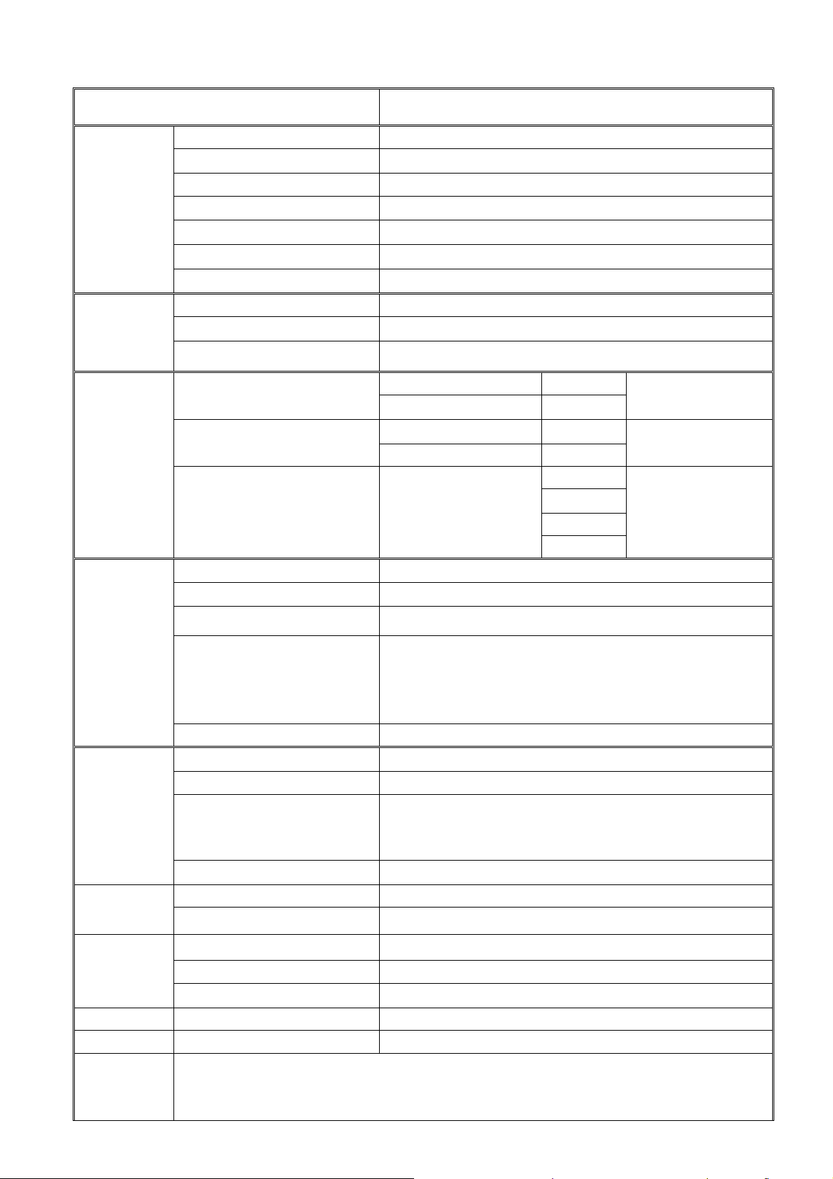
1-1 General Specification
Item Specification
Screen size 42 inch plasma display panel
Aspect
Display pixels 852 x 480 (WVGA)
Panel
Effective display size 932mm x 532mm
Spec
Number of color 16.7 million colors
Contrast Ratio 10000:1 (in dark room)
Peak brightness 1500 cd/㎡
TV Tuning 1 Tuners, Air:69 channels Cable:135 channels
TV Mode
Sound system M
Color system ATSC / NTSC
16:9
Video Mode
PC Mode
DVI Mode
Power
AV1 ( S_Video/Video)
Video RCA x 1 NTSC
Audio: L/R x 1
S-Video1 x 1 NTSC
AV2 ( S_Video/Video)
Video RCA x 1 NTSC
Audio: L/R x 1
S-Video2 x 1 NTSC
480i
AV3 / AV4
COMPONENT X 2
(YCbCr/YPbPr)
YCbCr/YPbPrx 2
1080i
480P
Audio: L/R x 2
720P
Signal input Analog:D-Sub 15 pin
Plug and play DDC / 2B
Support Frequency FH:31KHz to 80KHz , FV:50Hz to 85Hz
VESA: 640 x 480
D-Sub Mode
VESA: 800 x 600
VESA: 1024 x 768
VESA: 1280 x 1024
D-Sub Audio Earphone (3.5ø)
Signal input Digital:DVI-D 24 pin
Plug and play DDC / 2B
720P
DVI Mode
1080i
480P
DVI Audio Earphone (3.5ø)
Power input sources AC 100-240V , 50/60Hz
Power consumption ≤350W
Environment
Dimension
Net weight
Accessory
Operation Temperature + 0 °C ~ + 40 °C
Storage Temperature - 10 °C ~ + 50 °C
Humidity 10% -- 85%
Width x Height x Thickness 1038 x 726.5 x 240 (mm)
With Stand 34Kg
Remote Control Transmitter, Battery X 2, Power Cord, User’s Manual, RCA Cable,
D-SUB Cable, DVI Cable.
Page 4 of 83
Page 6

1-2 Feature Summary
The following is the specification summary for the display:
z 107 cm (42”) 16:9 Large Screen Flat Panel Plasma Display
z Resolutions: WVGA 852 (H) X 480(V) pixels, (1 pixel = 1 R, G, B cells)
z 1.095 mm (H) X 1.110mm(V) pixel pitch.
z Viewing Angle: 160° Vertically and Horizontally
z Internal TV Tuner, Air: 69 channels Cable: 135 channels
z Typical Maximum Contrast Ratio: 10000:1
z Typical Maximum Brightness: 1500 cd/m
2
z ATSC receiver, MPEG-2 decoder
z NTSC receiver, Video decoder
z Dual Video, Dual S-Video
z Dual Y Pb Pr (480i,480p,720p,1080i) HDTV Ready
z PC D-SUB 15Pin INPUT
z D-SUB analog video with rate 50Hz to 85 Hz vertical refresh rate and 31KHz to
80KHz horizontal frequency
z DVI-D Signal (TMDS) INPUT, Support HDTV, SDTV
z Closed Caption / V-chip
z Composite, S-Video, and component video receiver
z MIPS controller
z Auto Scan TV Channels
z Field upgradable firmware
z Universal Power Supply designed for worldwide application
z Operating power consumption less than 350 W
z Standby power consumption less than 1 W
Page 5 of 83
Page 7

1-3 External interface
Most of these interfaces are located at the back-panel. There’s also a group of connectors located
on the side of this device for easier access. The following figures depict these A/V connectors.
Side A/V Connectors
S-Video Video L R Earphone
AV2 Input
Back Panel A/V Connectors
Page 6 of 83
Page 8

1-3-1 Video/Audio Inputs
The following sections specify the video/audio inputs for A42W64AT4.
1-3-1-1 TV Antenna Interface
①. TV Antenna Connector
A42W64AT4 shall provide a F-type cable connector with 75 ohms termination on its back
panel for reception of radio frequency signals.
②. TV Systems
A42W64AT4 shall be capable of receiving the following broadcasting systems in the North
America region.
• Analog terrestrial and cable broadcasting in NTSC system and “M” sound system.
• All 18 formats specified for ATSC digital broadcasting
• Clear QAM digital cable broadcasting
③. TV Channel Coverage
The RF tuner shall be capable of covering 55.25 to 859.25 MHz and tuning to the following
channels:
• VHF: channel 2 through 13
• UHF: channel 14 through 69
• Mid band cable: A1 through A8, A through I
• Super band cable: J through W
• Hyper band cable: AA through ZZ, AAA, BBB
• Ultra band cable: channel 65 through 94, 100 through 125
④. Closed Caption
A42W64AT4 shall support closed caption and text mode for both video and TV system.
These supports shall include channel ½ and field ½ selectable features.
⑤. V-Chip
A42W64AT4 shall support MPAA grade for movie and TV Parental Guideline for TV. This
support shall include changeable password.
1-3-1-2 AV1
A standard definition (SD) analog video/audio source designated as AV1 shall be located on its
back panel. It comprises the following electrical connections. Only one of the two video inputs
shall be connected.
①. S-Video Input
A42W64AT4 shall provide a 4-pin mini-DIN connector for connection to an external
S-Video source.
②. CVBS Video Input
A42W64AT4 shall provide a RCA type receptacle for connection to an external CVBS
source.
Page 7 of 83
Page 9

③. Audio Inputs
A42W64AT4 shall provide two RCA type receptacles for the stereo audio signal associated
with AV1 input.
1-3-1-3 AV2
A standard definition analog video/audio source designated as AV2 shall be located at the side
of A42W64AT4. It comprises the following electrical connections. Only one of the two video
inputs shall be connected.
①. S-Video Input
A42W64AT4 shall provide a 4-pin mini-DIN connector for connection to an external
S-Video source.
②. CVBS Video Input
A42W64AT4 shall provide a RCA type receptacle for connection to an external CVBS
source.
③. Audio Inputs
A42W64AT4 shall provide two RCA type receptacles for the stereo audio signal associated
with AV2 input.
1-3-1-4 AV3
A YPbPr/YcbCr type component video interface designated as AV3 shall be located on its back
panel. It comprises the following electrical connections.
①. Video Inputs
A42W64AT4 shall provide three RCA type receptacles for connection to an external
component video source.
②. Audio Inputs
A42W64AT4 shall provide two RCA type receptacles for the stereo audio signal associated
with Component1 input.
1-3-1-5 AV4
A YPbPr/YcbCr type component video interface designated as AV4 shall be located on its back
panel. It comprises the following electrical connections.
①. Video Inputs
A42W64AT4 shall provide three RCA type receptacles for connection to an external
component video source.
②. Audio Inputs
A42W64AT4 shall provide two RCA type receptacles for the stereo audio signal associated
with Component2 input.
Page 8 of 83
Page 10

1-3-1-6 PC Input
A42W64AT4 accommodates a VGA type computer connection as specified below.
①. Video Input connector
A42W64AT4 shall provide a 15-pin D-Sub connector on its back panel for connection to a
VGA type video source. The VGA signal input on the display shall be capable of receiving
RGB analog video, H and V syncs, and DDC. The table below specifies pin-outs of this
connector.
Analog Connector Pin-outs
PIN
1 RV Red Video
2 GV Green Video
3 BV Blue Video
4 NC None
5 GND Ground (DDC Return)
6 RG Red GND
7 GG Green GND
8 BG Blue GND
9 +5 V +5 V (from the PC)
10 SG Sync Ground
11 NC None
12 SDA DDC Data
13 HS Horizontal Sync
14 VS Vertical Sync
15 SCL DDC Clock
②. Audio Inputs
A42W64AT4 shall provide a 3.5 mm jack for the stereo audio signal associated with VGA
input.
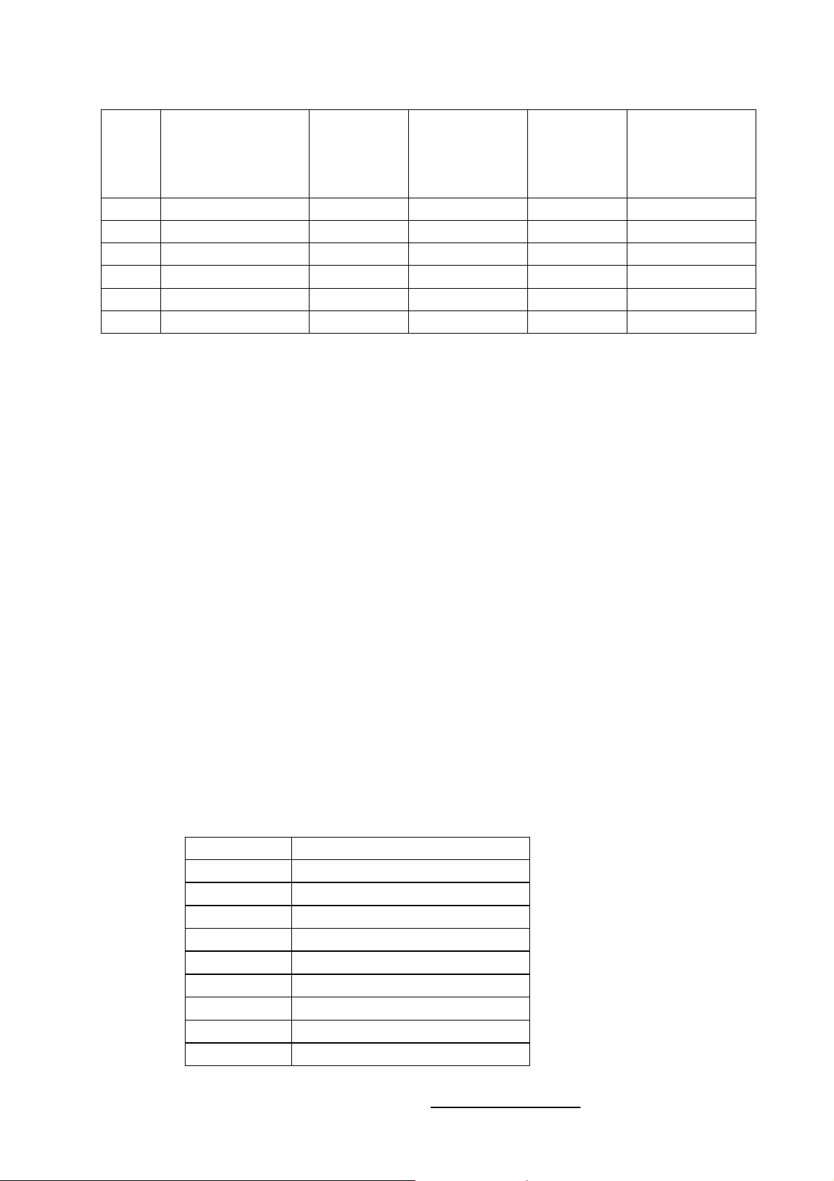
③. Input Formats
A42W64AT4 shall support the following input format on its VGA input.
Mode Resolution Total
MNEMONIC
SIGNAL
1
6
11 15
Horizontal Vertical
Nominal
Frequency
(KHz)
Sync
Pola-rity
Nominal
Freq.
(Hz)
5
Sync
Pola-rity
10
Nominal
Pixel
Clock
(MHz)
VGA 640x480@60Hz 800 x 525 31.469 N 59.940 N 25.175
SVGA 800x600@60Hz 1056 x 628 37.879 P 60.317 P 40.000
XGA 1024x768@60Hz 1344x806 48.363 N 60.004 N 65.000
WXGA 1280x1028@60Hz 1688x1066 64 N 60 P 108
Page 9 of 83
Page 11

1-3-1-7 DVI
A42W64AT4 shall accommodate a DVI type digital video source as specified in this section.
①. Video Inputs
A42W64AT4 shall provide a 24 contact DVI-D receptacle on its back panel for receiving
TMDS digital video. The table below specifies pin assignments for the DVI-D connector.
DVI-D Digital connector pin assignments
PIN MNEMONIC SIGNAL
1 TX 2 - TMDS Data 2 -
2 TX 2 + TMDS Data 2 +
3 SHLD 2 / 4 TMDS Data 2 / 4 Shield
4 TX 4 - TMDS Data 4 -
5 TX 4 + TMDS Data 4 +
6 DDC Clk DDC Clock
7 DDC Data DDC Data
8 N/C No Connect
9 TX 1 - TMDS Data 1 -
10 TX 1 + TMDS Data 1 +
11 SHLD 1 / 3 TMDS Data 1 / 3 Shield
12 TX 3 - TMDS Data 3 -
13 TX 3 + TMDS Data 3 +
14 +5V +5V Power (from the PC)
15 GND Ground (Return for +5V)
16 HPD Hot Plug Detect
17 TX 0 - TMDS Data 0 -
18 TX 0 + TMDS Data 0 +
19 SHLD 0 / 5 TMDS Data 0 / 5 Shield
20 TX 5 - TMDS Data 5 -
21 TX 5 + TMDS Data 5 +
22 TX CLK SHLD TMDS Clock Shield
23 TX CLK + TMDS Clock +
24 TX CLK - TMDS Clock -
②. Audio Inputs
A42W64AT4 shall provide a 3.5 mm jack for the stereo audio signal associated with DVI
input.
③. HDCP support
HDCP must be supported on the DVI input. Refer to the High-bandwidth Digital Content
Protection System specification version 1.1 for details.
Page 10 of 83
Page 12
④. Input Formats
A42W64AT4 shall support the following input format on its DVI input.
Nominal
Mode Resolution Total
VGA 640x480@60Hz 800 x 525 31.469 59.940 25.175
SVGA 800x600@60Hz 1056 x 628 37.879 60.317 40.000
XGA 1024x768@60Hz 1344x806 48.363 60.004 65.000
720P 1280×720P 45.00 60 74.25
1080i 1920×1080i 33.75 60 74.25
480p 720×480p 31.54 60 27.00
HFrequency
(KHz)
Nominal
Vertical
Frequency
(KHz)
Nominal Pixel
Clock Frequency
(MHz)
1-3-2 Power Interface
1-3-2-1 Power Connector
A42W64AT4 shall support an IEC C-13/C-14 (Standard) type male power receptacle for
connection to AC power source.
1-3-2-2 Power Input Range
The operating range shall be from 100 to 240 VAC sinusoidal. Input power frequency range shall
be from 50 to 60 Hz over the specified input voltage range.
1-3-2-3 Power Consumption
①. Operating Power
Power consumption for the display over the specified voltage and frequency ranges shall be
less than 350 W for the assemblies with speakers.
②. Standby Power
A42W64AT4 power also below than one watt in the standby mode.
1-3-3 Service Interface
A42W64AT4 shall provide a 9-pin D-sub connector on its back panel for firmware upgrading
purpose. This interface shall conform to RS-232 standard with the following pin-outs.
Pin Function
1 NC
2 TXD transmitted data
3 RXD received data
4 Shorted with pin 6
5 FG frame ground
6 Shorted with pin 4
7 Shorted with pin 8
8 Shorted with pin 7
9 NC
The method of firmware upgrading please see “Flash update process” chapter.
Page 11 of 83
Page 13
1-4 User interface
1-4-1 Power Indicator
A42W64AT4 shall make use of an LED type indicator located on the front of the display. The
LED color shall indicate the power states as given in the following table.
LED colors
Mode H-Sync V-Sync Video Pw-cons. Indicator
Power-On On On Active <350W Blue LED
Standby Off Off Off <1W Red LED
1-4-2 Remote Control Receiver
A42W64AT4 shall provide an infra-red (IR) optical detector on its front panel for use as the
receiver for remote controller signal. The IR communication protocol shall conform to RC-5
standard. The minimum IR reception angles shall be +/- 30 degrees horizontally and vertically.
The required operating distance of the remote control shall be 7 m.
1-4-3 On-Screen Display
A42W64AT4 shall provide an On Screen Display (OSD) system for customer setup. The
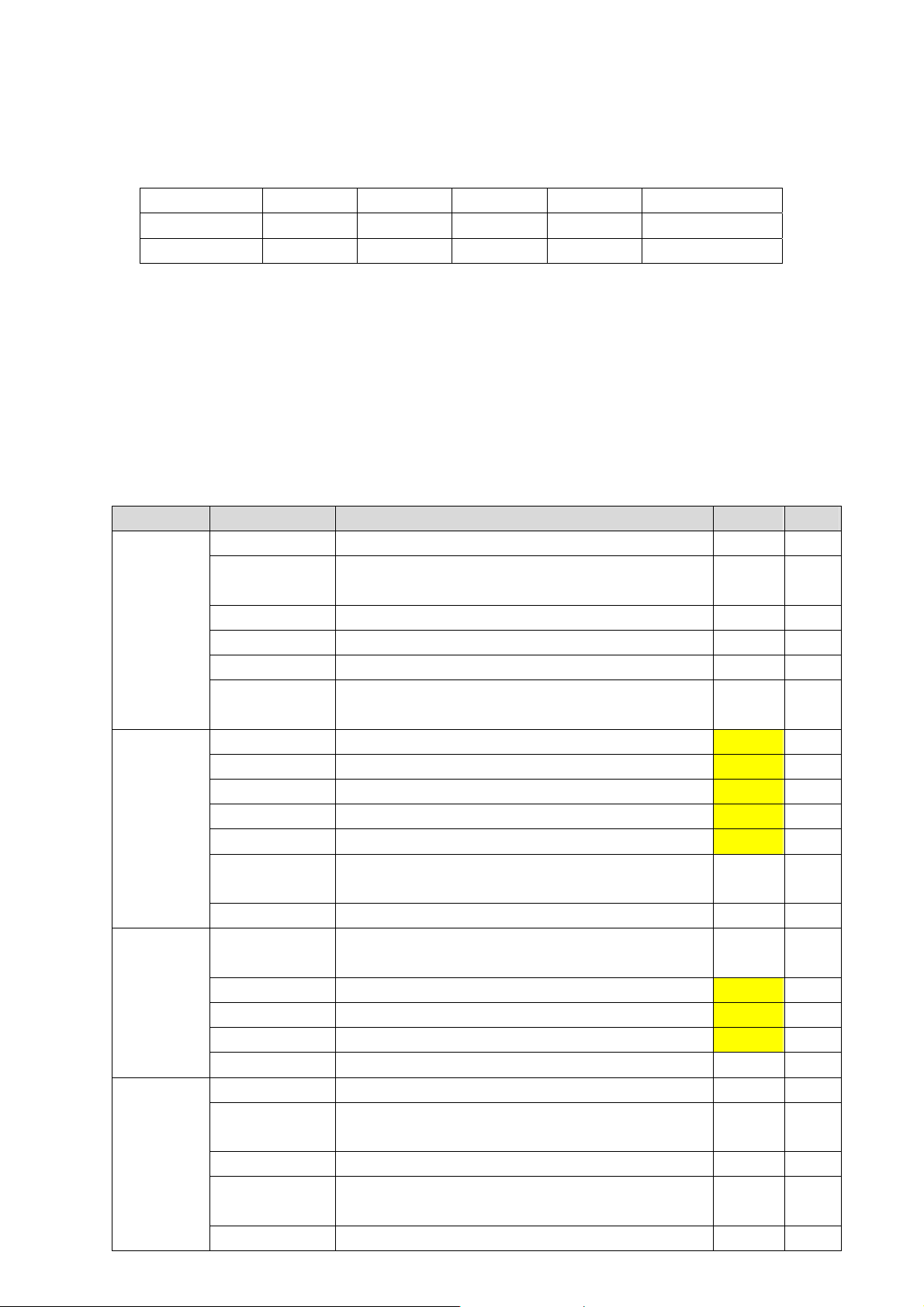
following table gives the structure of the OSD menus.
Main menu Sub menu Function Default Reset
SETUP
Tuning Band To select between Air and Cable System Air —
DTV Signal
To display the signal strength in order to aid the
antenna adjustment
— —
Auto Ch Search To automatic scan and store all TV channels — —
Manual Ch Set To enable or disable channels — —
Channel Label To rename a channel — —
VIDEO
Manu
Language
CONTRAST To adjust the contrast value between 0~100 50 Yes
BRIGHTNESS To adjust the brightness value between 0~100 50 Yes
SHARPNESS To adjust the sharpness value between 0~100 50 Yes
COLOR To adjust the color value between 0~100 50 Yes
TINT To adjust the tint value between 0~100 50 Yes
Aspect Ratio
To select the language for OSD among English,
Spanish, French, and Portuguese
To select aspect ratio among Normal, Zoom,
Wide, and Cinema
English —
Normal Yes
Settings To restore all video settings to factory default — —
AUDIO
Audio
Language
BASS Sets the bass value between 0~100 31 Yes
TREBLE Sets the treble value between 0~100 31 Yes
To select audio language among English,
Spanish, French, and Portuguese
English Yes
BALANCE Sets the left/right balance value between 0~100 31 Yes
Restore Default To restore all audio settings to factory default — —
FEATURE
Time Set To set current time — —
Sleep Timer
To set the timer period to turn off the TV.
Selectable values are OFF,30,60 and 90 minutes
OFF —
Password Set To set or change Parental Control password TBD —
Parental
Control
To select V CHIP settings
Un-lock
ed
White Screen To make a White screen by TV ifself. — —
Page 12 of 83
—
Page 14

1-5 External Mounting Requirements
A42W64AT4 shall be designed so that the display enclosure can be easily removed from the base
for external mounting applications. When the base is removed, there shall be no additional
non-removable parts that are visible from the front of the display
1-6 Environmental Requirements
1-6-1 Temperature Ranges
Operating Temperature (Independent of altitude)
Non-Operating Temperature (Independent of altitude)
.................................................. 0°C to 40°C
................. ..................... -10°C to 70°C
1-6-2 Humidity
Operating (non-condensing)
Non-Operating (38.7°C maximum wet bulb temperature
.................... ...............................................................20% to 85%
........ ........... ....................5% to 85%
1-6-3 Altitude
Operating
Non-Operating
............................................................... ...................... ...................... (0 to 2,000 m)
............................... .................................... ........ . ...................... (0 to 3,000 m)
1-6-4 Vibration and Shock
All testing shall be done in each of three mutually perpendicular axes, referenced to the position
of the system as it is in front of the user (i.e., front-to-back, side-to-side, and top-to-bottom).
2、Precautions and Notices:
2-1 Precaution of assembly
(1)Please do not press or scratch PDP panel surface with anything hard.
(2)Please wipe out PDP panel surface with absorbent cotton or soft cloth in case of it being soiled
(3)Please wipe out drops of adhesive like saliva and water in PDP panel surface immediately. They might
damage to cause panel surface variation and color change
(4)Do not apply any strong mechanical shock to the PDP panel
2-2 Precaution of Operation:
(1)Please be sure to unplug the power cord before remove the back-cover. (make sure the power is turn-off)
(2)Please do not change variable resistance settings in PDP MODULE; They are adjusted to the most
suitable value. If they are changed, it might happen LUMINANCE does not satisfy.
(3)Please consider that PDP MODULE takes longer time to become stable of radiation characteristic in
low temperature than in room temperature.
(4)Please pay attention to displaying the same pattern for very long-time. Image might stick on PDP.
Page 13 of 83
Page 15
y
3、Operation
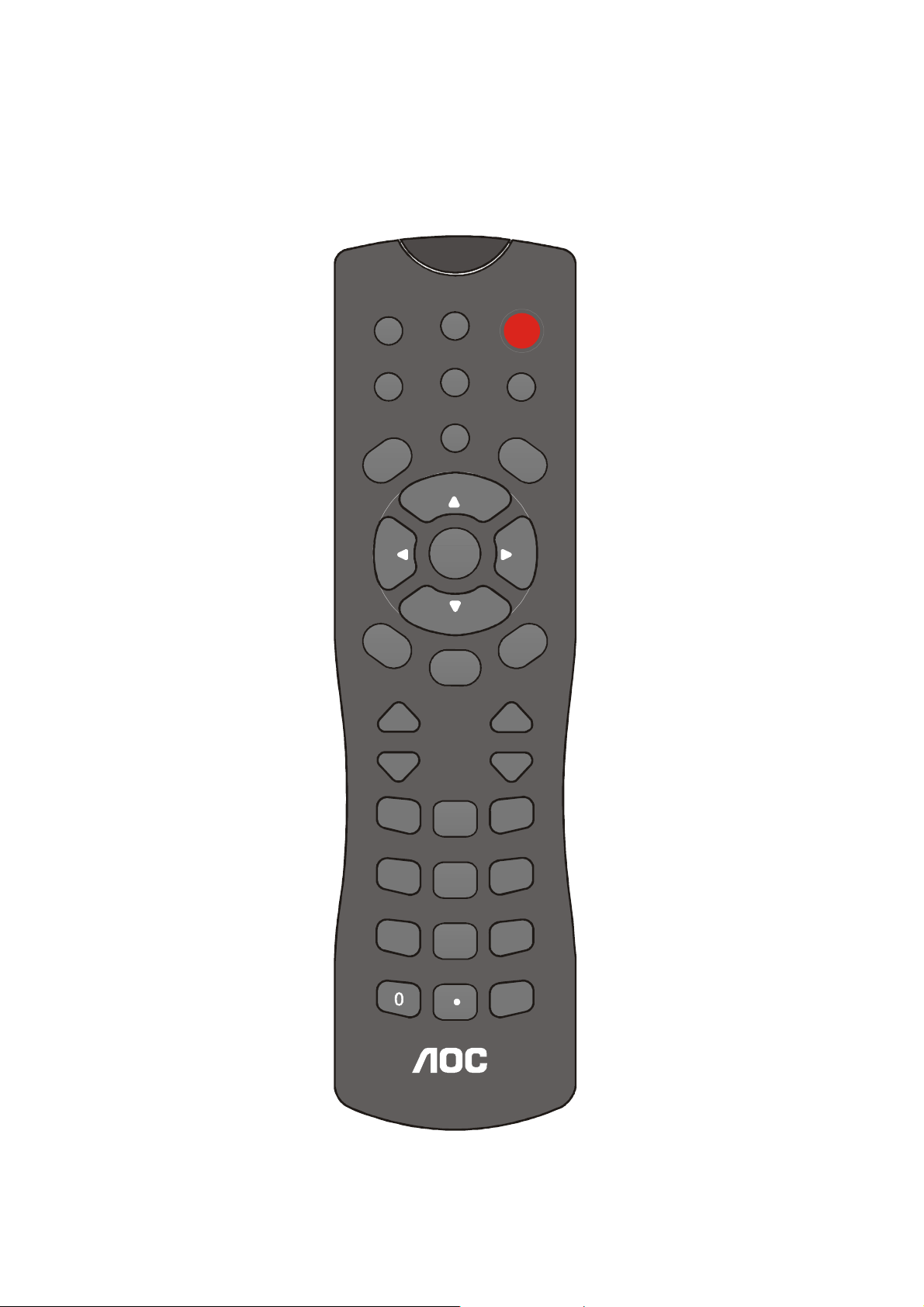
3-1 Operation of Remote Control Transmitter
A42W64AT4 shall provide an IR remote controller as accessory.
Normal, Zoom ,Wide, Cinema
Display the state, source
TV source select, into TV state
Select timer into power down state.
off→30→60→90→off
options(CC1,CC2……)
To select close caption
To enter sub Menu or sub item .
To enter Menu mode .
Press Vol up/ Vol down
key to adjust volume .
To enter TV channel number
To enter sub channel number
for digital channels .
“Wide Mode”
display select
“EPG”
“TV”
“SLEEP”
“CC”
“ENTER”
“MENU”
“MUTE”
Mute the sound
“Vol up / Vol down”
“0~9 number”
“ z ”
Wide Mode
TV
C
C
left
M
e
n
u
Vol up
Vol down
1
4
Page 14 of 83
EPG
Video
SLEEP
Up
Enter
Down
Mute
2
5
8
POWER
Digital
M
right
E
CH up
CH down
3
6
97
Pre-CH
“POWER”
The TV Set turn on /turn off ke
“Video”
AV1 CVBS Rear /AV1 S-Video
Rear/ AV2 CVBS Side/ AV2
S-Video Side / AV3 component 1/
AV4 component 2
T
S
“Digital”
VGA/DVI source input
“MTS ”
To select audio program
options
“Up▲/Down▼”
T
I
X
Move the cursor up and down on
the Menu
“left ◄ / right ►”
Use left ◄/ right ► to select or
adjust an item.
“EXIT”
To exit Menu or other OSD .
“CH up / CH down”
Press to select the next lower or
higher Program number.
“Pre-CH”
TV channel return, see last TV
channel .
Page 16

3-2 Front panel controls
①
②
③
④
⑤
⑥
⑦
①
② ● LED: Power Indicator.
③
IR: Remote Control Sensor.
Power switch: Press to power on or power off the TV set..
- CH + - VOL +
MENU MODE
Down: Press to select the next lower Programme number or move Down in
④ -CH+
Menu operation.
Up: Press to select the next higher Programme number or move up in Menu
operation.
⑤ -VOL+
Left: Press to decrease the sound volume level or move Left in Menu operation.
Right: Press to increase the sound volume level or move Right in Menu operation.
⑥ MENU Menu: Press to enter Menu or exit Menu.
⑦ MODE Mode: Press to select input signal modes or use as Enter in Menu operation.
Page 15 of 83
Page 17
3-3 OSD MENU Description
3-3-1 Main MENU
1. Press “MENU” key on remote control or
front panel controls to bring up Main Menu.
2. Press “
and down the sub menu list.
3. Press “
4. Press "Enter" to enter sub-item then use
” or “” to adjust.
“
” or “” to move the cursor up
” or “” to select sub menu item.
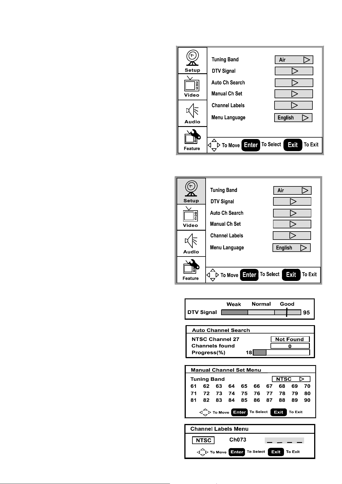
3-3-2 SETUP MENU
1. Tuning Band: Select TV signal source
between Air and Cable. Select Cable if you
are connecting to a cable box and select Air
if you are directly connecting to the antenna.
2. DTV Signal: Display signal strength to aid
antenna adjustment.
3. Auto Ch Search: Automatically scan and store
all TV channels.
4. Manual Ch Set: Enter channel setup table.
5. Channel Labels: Display and edit channel
names.
6. Menu Language: Select language for menu
(EnglishEspañolFançaisPortuguese).
y DTV signal menu indicates signal strength
in real-time.
y Auto channel scan menu displays channel
number being scanned.
y Manual Channel Set Menu
Displays all the channel numbers that are
found.
Tune either to ATSC or NTSC channels.
Add or delete Channel number.
y Channel Labels Menu allows user labeling.
Page 16 of 83
Page 18
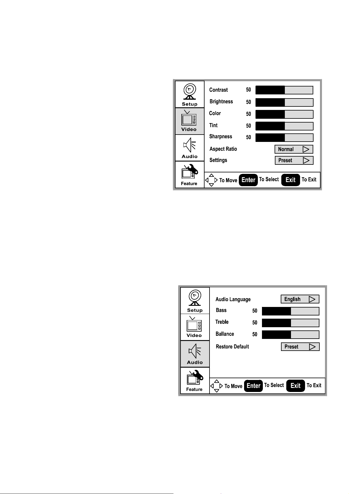
3-3-3 Video MENU
1. Press “” or “” to move the cursor up
or down the sub-item list.
2. Press "Enter" to enter the highlighted
sub-item menu.
3. Press “
the sub-item.
” or “ ” to adjust the value of
4. Press "Enter" again to exit the sub-item.
Contrast: Contrast adjustment, 0~100.
Brightness: Brightness adjustment, 0~100.
Color: Color chroma adjustment, 0~100.
Tint: Tint adjustment, 0~100.
Aspect Ratio: Aspect Ratio selection.
Normal
ZoomWide Cinema.
Settings: Restore default setting.
3-3-4 Audio MENU
1. Press “
2. Press "Enter" to enter the highlighted
3. Press “
4. Press "Enter" again to exit the sub-item.
Audio Language:
EnglishEspañolFrançaisPortuguese.
Bass: Bass adjustment, 0 ~ 100.
Trebl e: Treble adjustment, 0 ~ 100.
Balance: Balance adjustment, 0 ~ 100.
Restore Default: Restore Audio Language,
Treble, Base, and Balance setting to default.
” or “” to move the cursor up
or down the sub-item list.
sub-item menu.
” or “” to adjust the value of
the sub-item.
Page 17 of 83
Page 19
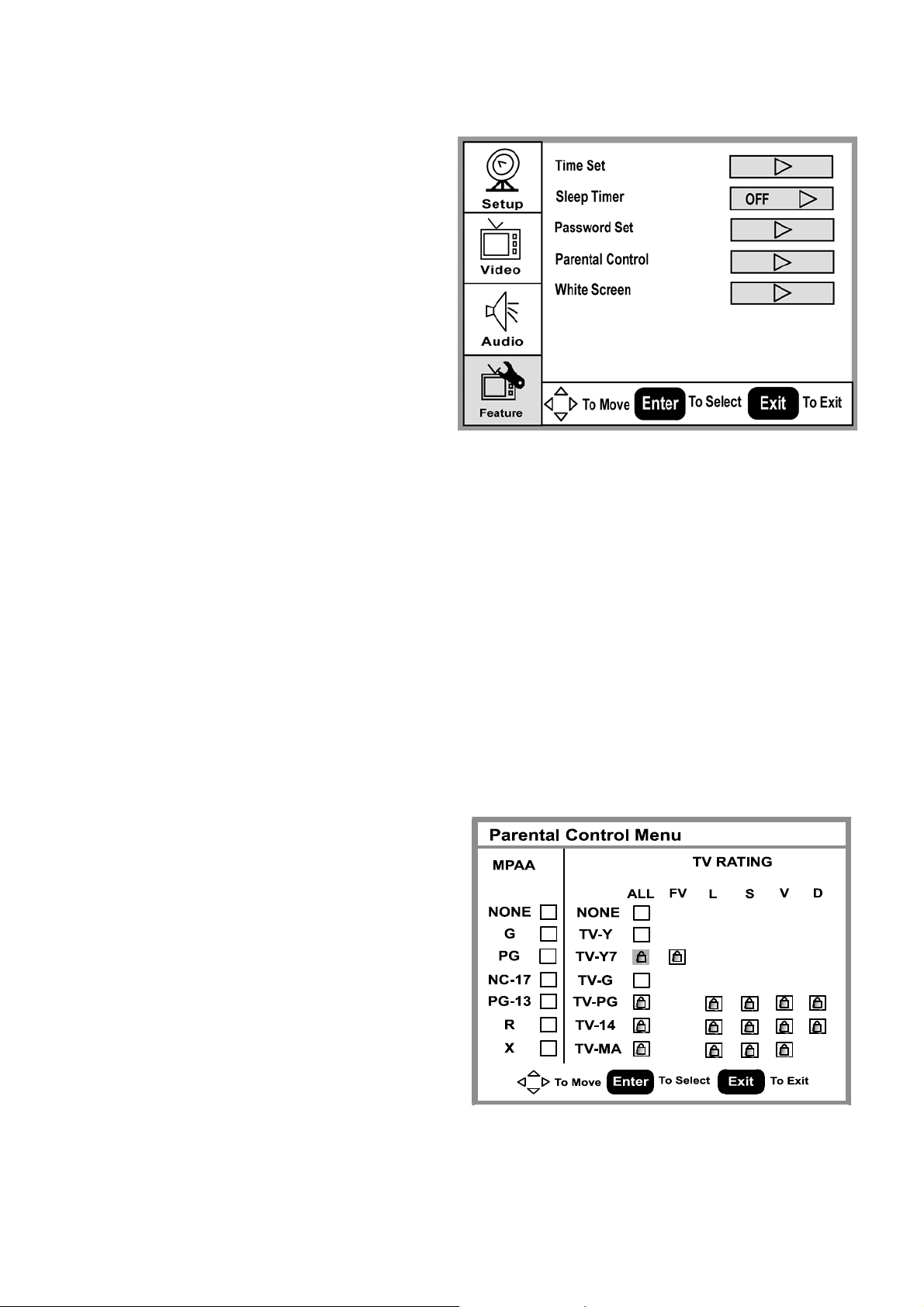
3-3-5 Feature MENU
1. Press “
2. Press "Enter" to enter the highlighted
3. Press “
4. Press "Enter" again to exit the sub-item.
Time Set: Select minutes into standby
Password Set: Enter and change Parental
Parental Control: Setup TV and Movie
White Screen: Select White Screen, and
press MODE front panel button (Enter on
the Remote control).The TV immediately
displays the white screen.
Parental Control Menu: Controls
viewing of rated TV and Movie
programs.
Default password is: 0000.
Important : If you have forgotten your
Password. Use the code [0711] to enter
into the Password Set menu item to
change your password. You can also
use the code [0711] to change your
Parental Controls settings.
” or “” to move the cursor up
or down the sub-item list.
sub-item menu.
” or “” to adjust the value of
the sub-item.
Off
30 60 90
.
Control Password.
rating controls.
Page 18 of 83
Page 20

CS
CC
ATSC TV
3-3-6 Closed Captions
1. Press “CC” key on remote control to select closed captions mode.
NTSC TV: Off CC1 CC2 …
ATSC TV: Off CS1 CS2 …
2. Select desired closed caption mode.
3.Closed captioning for analog NTSC channels is transmitted as CC1/CC2/CC3/ CC4. Closed
captioning for digital channels is transmitted as CS1/CS2/CS3/CS4/ CS5/CS6 or occasionally
CC1/CC2/CC3/CC4. You need to select the option you want for analog channels and digital
channels separately.
1
3-3-7 EPG
Press the “EPG” key on the remote control
to display the Electronic Program Guide
(EPG). A message window will be
displayed on screen.
3-3-8 TV channel arrangement
Each digital channel may comprise of
several sub-channels.
To select a digital channel using the remote
control:
1. Enter main channel number.
2. Press the “•” key.
3. Enter the sub-channel number.
1
EPG Message Window
Ch 5.4
Page 19 of 83
Page 21
4、Trouble shooting chart
If replace “IMAGE BOARD”, Please re-do “DDC writing” program & “WHITE-BALANCE” & Flash
Update.
If replace PANEL module, Please re-do “white-balance adjust”
4-1 PANEL Trouble shooting
Please reference the “PANEL Service Manual”.
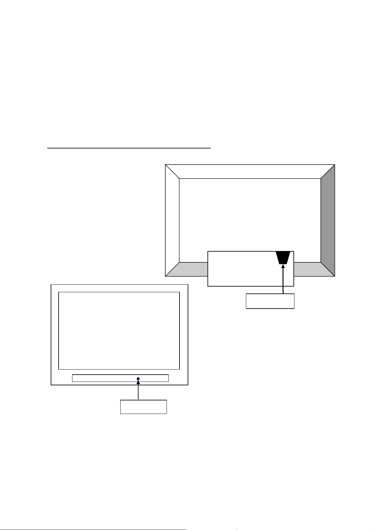
4-2 Turn PDP on and Check:
Plug power cord into pdp set, and the color of LED is red;
If PDP under the normal working, display of LED is blue. Then, the screen show is nor dark. If the color of
LED is red under standby state, you should press the “power” bottom of remote control or you should press
the front standby key. Then, turn PDP TV on.
If it is nothing about OSD or display on screen, service PDP.
The procedure and maintain the step meet as follows:
LED Light
Page 20 of 83
Power Cable
Page 22

p
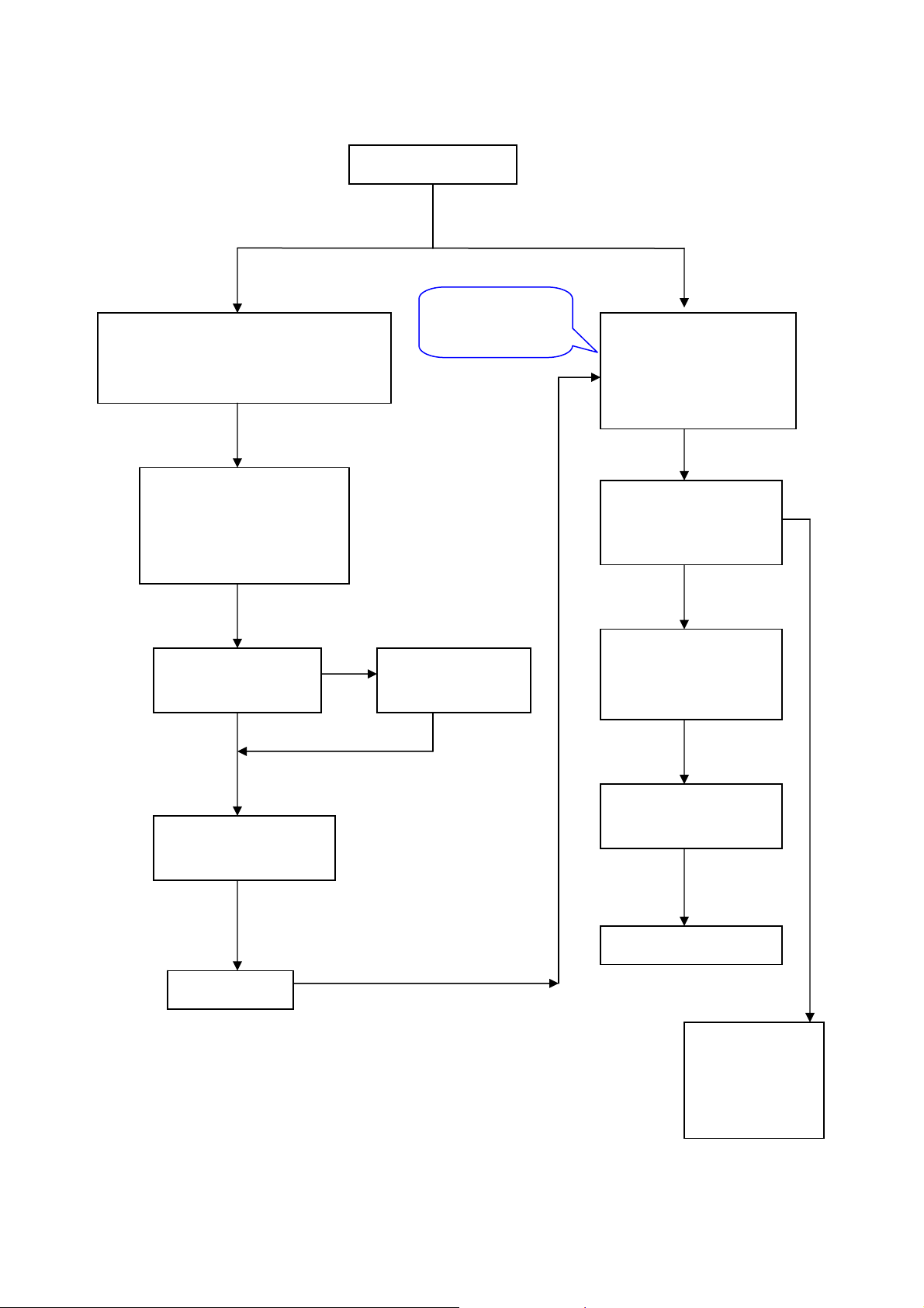
4-2-2 Solution process of whole PDP:
Screen is nothing under power on
Check the REL-SW state of power IO
interface,
High Voltage:Turn on
Low Voltage:Standby
Test Point: C pole of Q5
High Voltage:5V(4.2---5.3V)
Low Voltage:0V
Check device circuit and logic circuit,
Vs, Vset, Vsc, Ve etc.
Arrow shows test point.
Check AC input of PDC
Check PowerSTB5V(U516 3PIN)
Voltage: 5V
If REL-SW is ok,check other
power.
If there was anything
unmoral, test voltage and
air it.
re
Process of repair as follow
Q5
Page 21 of 83
U516
Q5
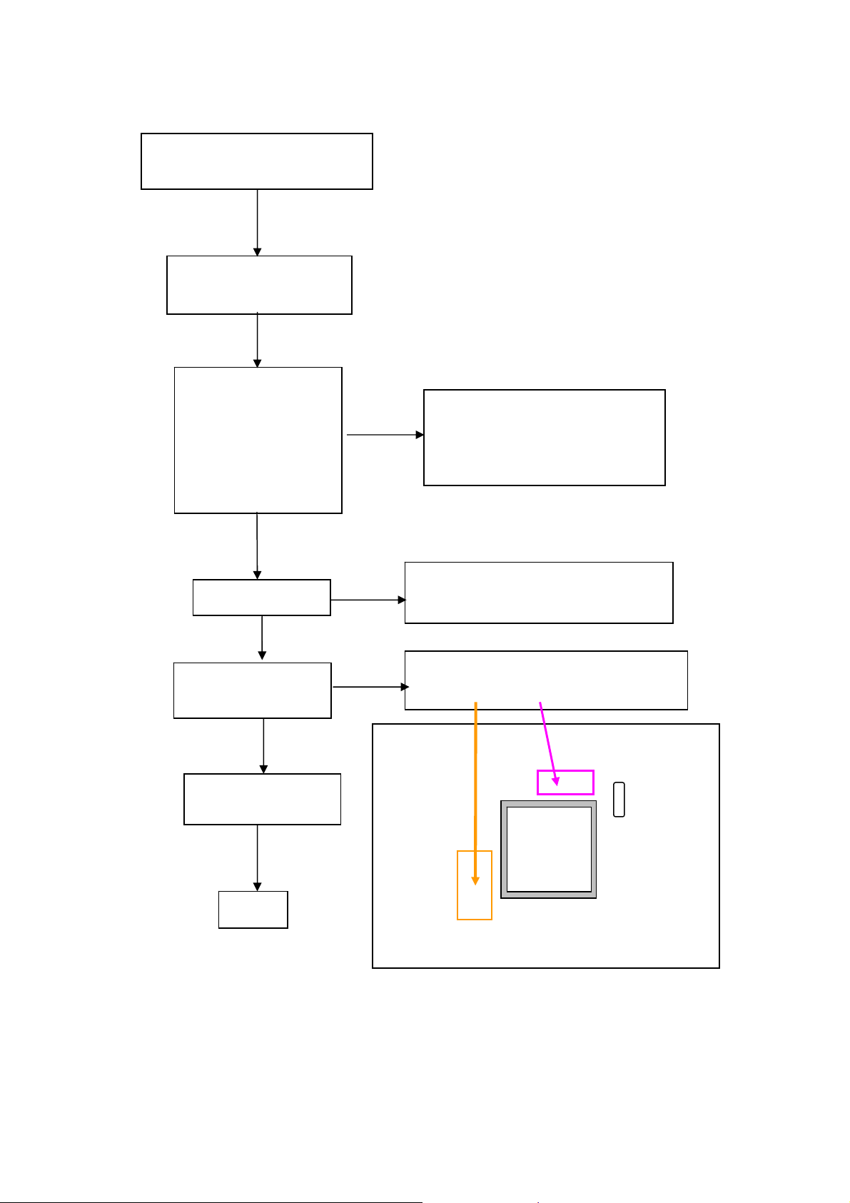
Image board
CN703
CN704
R128
Check the voltage of CN703:
PIN5 --Æ 12 V
PIN8 --Æ 3.3 V
PIN9 --Æ 3.3 V
PIN11 --Æ 6 V (Samsung PANEL)
Fig1: Voltage sheet
Name Voltage Reference
VS 209V Voltage for driving sustain
VA 70V Voltage for driving address
VE 82V Voltage for driving X-bias
VSET 198V Voltage for driving reset
Vscan -198V Voltage for driving scan
Vg 15V Voltage for driving FET
D3V3 3.5V Voltage for driving logic
Page 23
4-2-3 STB POWER Solution process
No input of +5VSB,or output is unmoral
Test point:CN903 PIN2
Voltage:5V(4.9-5.1)
NG
Test AC Input of CN901 ok
or not?
Voltage:AC 100 V ~ 120 V
/200 V ~ 240 V
OK
Test voltage of C905
is DC300V or not?
OK
Check IC901 and D901
ok or not?
OK
+5VSB OK
Note:Must distinguish connect Grand point of Power primary and secondary level.
POWER un-moral
NG
Check FUSE F901,
BD901ok or not?
Do these process
under the state is
+5VSB
Page 22 of 83
No input of AC Power
out, or output is unmoral
Test point:CN902
Voltage: AC INPUT±1V
PS-ON ok or not?
Test point:CN903 PIN4
Voltage:DC5V(High)
Vccp ok?
Test pads of C909
Voltage:DC13V-25V
Q901, Q902, Q903, Q904,
M902 ok or not?
AC POWER-OUT OK
NG
NG
OK
OK
OK
Check circuit of
IMAGE BOARD,
and check PS-ON
OK or not?
Page 24

4-2-4 Solution processes for DC Power
Check the junction that CN703 to
CN704 or CN701 to CN702 ok
or not?
OK
Test input voltage:
L701 --Æ 12 V
L703 --Æ 6 V
L721 --Æ 3.3 V (Samsung PANEL)
Test voltage as follow:
L705--Æ8V
L706--Æ5V
L704--Æ5V
L718--Æ2.5V
L719--Æ1.2V
OK
4-2-5 Solution processes for SCALER
Check power supply , input
and output signal of U1
(ZR391055) and U2
(DS90C2501)ok or not?.
OK
Check input and output signal of
U8,and TX0-/TX0+ signal etc. ok
or not?
OK
NG
NG
Page 23 of 83
NG
Is there any short or
cold solder?
Is there any short or
cold solder?
Replace U8
Page 25
y
r
4-2-6 Solution processes VIDEO
No display under Video, S-video,
YCbCr and YPbPr mode
Check the state of power
switch ,and DC power.
OK
1.Test input signal of U14
under VIDEO and
S-VIDEO mode
2. Test input signal of U1
at C18/C19/C20 under
YCbCr mode
OK
Check U1
OK
Check circuit of U6
(PW1231) ok or not?
OK
Check circuit of U20
(SCALAR)and LVDS
OK
NG
NG
NG
Page 24 of 83
Is there any short or disconnection,
and signal is wrong.
(The signal of standard color bar
will be ver
Is there any short or disconnection, CLK
and SYNC signal to U1circuit?
Is there any short or disconnection, CLK
and SYNC signal to U6 circuit?
clea
)
X5
U6
Page 26

5、White-Balance Adjustment
5-1 Equipments list
Chroma7100 1set
VG828 video signal generator 1set
Chroma-2326 1set
5-2 Preparation and Adjustment process
1、 Preparation:
z Connect rear Video port of PDP with AV port of VG-828.
z Connect component port of PDP with YPbPr port of VG-828
z Connect VGA port of PDP with corresponding port of Chrom2326
z Turn power of PDP and test instrument on.
z Before open lens, Press O-CAL of Chrom-7100 and revise lens.
2、Adjustment process
AV Adjustment
1). Change to Video mode, you can press “SOURCE” of remote. Press “Vol - ”, adjust volume
until Min. Then press number key “6543”and enter factory Menu.
2). Press “SOURCE” and change to Video Rear mode
3). When setting of VG-828 is TIM946/PAT922, 32 Gray steps. Then, see the color of picture
is deflection or not. And the Gray steps distinguish 28 steps from 32steps or not.
①. If dark of Gray is deflection, press “CH+/-”and adjust:
1.White.BRoCVBS (vMin=0,vMax=100,vDef=50) →50,
2.White.BBoCVBS (vMin=0,vMax=100,vDef=50) →50,
3.White.BGoCVBS (vMin=0,vMax=100,vDef=50) →50,
②. If sharpness of Gray is deflection, press “CH+/-”and adjust:
4.White.BRgCVBS (vMin=0,vMax=100,vDef=50) →50,
5.White.BBgCVBS (vMin=0,vMax=100,vDef=50) →50,
4). When the Gray is ok, change input signal to white picture at P936, Use colored analysis
instrument Chroma7100 measure colors temperature value of picture at present (whether
Chroma7100 is it given to picture center to pop one's head), On pressing the remote
controller such as the specification of going beyond "program + /- "key choose following
the projects adjust:
4.White.BRgCVBS (vMin=0,vMax=100,vDef=50) →50,
5.White.BBgCVBS (vMin=0,vMax=100,vDef=50) →50,
Page 25 of 83
Page 27

5). When adjustment about white is ok, changes signal to P822 that Gray steps picture. The
Gray picture has no deflection color, and the Gray steps distinguish 28 steps from 32steps
Note: The white balance is adjusted in the course, will influence each other to adjust in the
adjustment of gray steps and white picture, and need to change repeatedly.
Please notice that can't enter the mode of the factory in every station homework after adjusting
and finishing, so as not to miss movements and revise the white balance data again.
VGA Adjustment
Setting of Chroma2326 as follows:
Gray picture: TIM4/PAT48
White picture: TIM4/PAT105
Change to VGA mode, press “CH+/-”and adjust following items. Method same as AV mode:
6. White.BRoVga (vMin=0,vMax=100,vDef=50) →50,
7. White.BBoVga (vMin=0,vMax=100,vDef=50) →50,
8. White.BGoVga (vMin=0,vMax=100,vDef=50) →50,
9. White.BRgVga (vMin=0,vMax=100,vDef=50) →50,
10. White.BBgVga (vMin=0,vMax=100,vDef=50) →50,
Note: Press “Source” and change mode that Video Rear to VGA, then adjustment items of
white balance same as Video Rear First, press “CH+/-” and adjust under the VGA mode.
(White.BBgCVBS(vMin=0,vMax=100,vDef=50)→50 CVBS change to VGA)
COMPONENT Adjustment:
1). VG828 setting as follow:
Gray picture:TIM954/PAT922
White picture:TIM954/PAT936
2). Change to COMPONENT1 mode,press “CH+/-”and adjust following items. Method same
as AV mode:
1. White.BRoVga (vMin=0,vMax=100,vDef=50) →50,
2. White.BBoVga (vMin=0,vMax=100,vDef=50) →50,
3. White.BGoVga (vMin=0,vMax=100,vDef=50) →50,
4. White.BRgVga (vMin=0,vMax=100,vDef=50) →50,
5. White.BBgVga (vMin=0,vMax=100,vDef=50) →50,
Adjustment stand of white Balance: x=299±15,y=315±15
Page 26 of 83
Page 28

6、DDC program and test
6-1 Equipments list and prepare
DDC tester 1PCS
PC 1SET
D-SUB cable 1PCS
DVI cable 1PCS
Barcode Reader 1SET
Prepare before test:
1. Turn on the power of your PC and programmer, then make good connection of them.
2. Connect the D-SUB wire and DVI wire to the DDC program equipment and the PDP monitor.
6-2 Program and test process
1. Choose different DDC menu according to different customer , do use PAGE DOWN/PAGE UP to go to the
submenu and parent menu until find the right model. Press enter to access the program interface. There will
be shown RGB on the screen. Then switch to RGB program on the DDC connector。Press any key to access
RGB program interface ,then there will be “input serial no.:” prompt on the screen.
2. Use Bar Readers to read the serial no to the program,then make sure the serial no you have read is the same as
on the barcode. Then set the PDP to blue screen mode, press enter to start.
3. Watch the information of the program, it means programmed OK when the following interface come out.
please CHECK Manufacturer Name、Vendor Assigned Code、Model Name、Serial Number:
****[?????????****](same as Barcode)、Week of Manufacture:**、Year of Manufacture:****、Checksum:
**(same as the last byte of data table, reference to the note of RGB programming picture)and so on.
4. Press Enter to access RGB DDC test interface,follow the DDC test picture,CHECK Manufacturer Name、
Vendor Assigned Code、Model Name、Serial Number:****[?????????****](same as Barcode)、Week of
Manufacture:**、Year of Manufacture ****、Video Input:Analog、Checksum:**(same as the last byte
of data table, reference to the note of RGB programming picture)and so on.
5. Press any key to access DVI program interface, there will be “DVI” shown on the screen. Switch the of
switch on the DDC connector, press any key to access DVI program interface, there will be “input serial
no.:” promote.
6. Use Bar Readers to read the serial no to the program,then make sure the serial no you have read is the same
as on the barcode. Then set the PDP to blue screen mode, press enter to start.
7. Watch the information of the program, it means programmed OK when the following interface come out.
please CHECK Manufacturer Name、Vendor Assigned Code、Model Name、Serial Number:
****[?????????****](same as Barcode)、Week of Manufacture:**、Year of Manufacture:****、Checksum:
**(same as the last byte of data table, reference to the note of DVI programming picture)and so on.
8. Press Enter to access DVI DDC test interface,follow the DDC test picture,CHECK Manufacturer Name、
Vendor Assigned Code、Model Name、Serial Number:****[?????????****](same as Barcode)、Week of
Manufacture:**、Year of Manufacture ****、Video Input:Analog、Checksum:**(same as the last byte
of data table, reference to the note of DVI programming picture)and so on。If the recording is failure, check
the connection of equipment and record again from the step4.If all of these work does not take work ,please
ask IE department for help.
9. Notice :the “?” and “*” symbol will be changed according to the year of manufacture ,and so on.
Page 27 of 83
Page 29
7、Flash Update
7-1 The list of Instrument
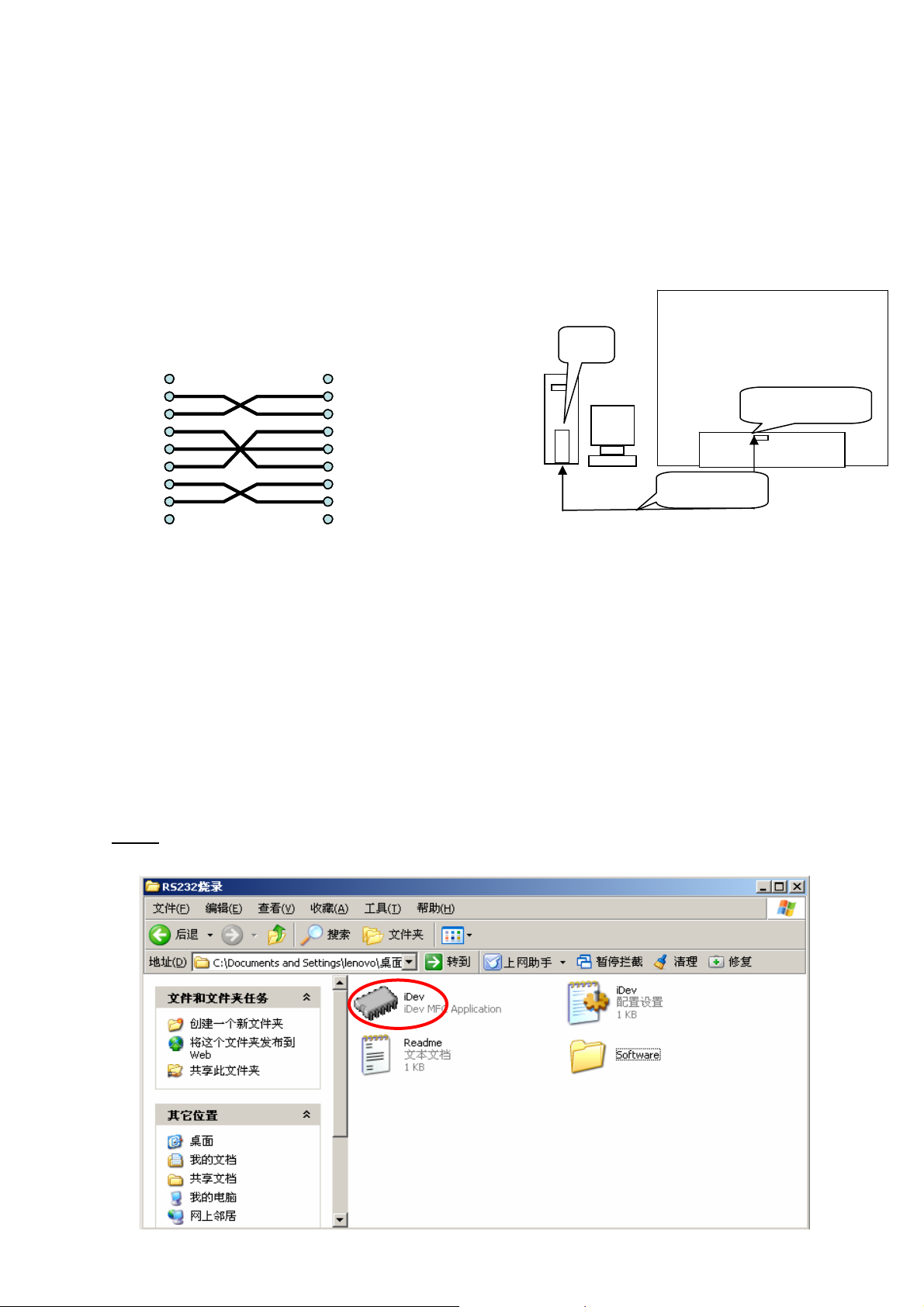
1、Prepare 1 piece of RS232 cable(The Pin connection see the Figure-1,If difference, please re-connect the
cable)and 1 set of PC.
2、 Connect the RS232 cable with PC and PDP(See the Figure-2).
To Philips PDP
To PC
To PC
To PC
To PC
Pin (Female)
Pin (Female)
Signal Pin
Signal Pin
RXD 2
RXD 2
RXD 2
TXD 3
TXD 3
TXD 3
DTR 4
DTR 4
DTR 4
GND 5
GND 5
GND 5
DSR 6
DSR 6
DSR 6
RTS 7
RTS 7
RTS 7
CTS 8
CTS 8
CTS 8
1
1
1
9
9
9
To Philips PDP
To Philips PDP
To Philips PDP
9 Pin (Female)
9 Pin (Female)
Signal Pin
Signal Pin
Figure-1 Figure-2
7-2 The operation explaining Flash Update
Note: Operation Under the situation of PDP working normally.
The iDev is a Windows utility that installs hex files into the FLASH ROM of the target Image Processor
system. iDev is a Windows-based application.
Downloading is done through an RS-232 connection, which is bidirectional and serial.
Step 1: Open the file iDev (You should
1
1
2 RXD Received Data
2 RXD Received Data
3 TXD Transmitted Data
3 TXD Transmitted Data
4 DTR Data Terminal Ready
4 DTR Data Terminal Ready
5 GND Signal Ground
5 GND Signal Ground
6 DSR Data Set Ready
6 DSR Data Set Ready
7 RTS Request To Send
7 RTS Request To Send
8 CTS Clear To Send
8 CTS Clear To Send
9
9
PC
PDP
RS232 Connector
RS232 Cable
Page 28 of 83
Page 30

Step 2: Choose the director of the file to flash
Note: Connect the computer’s serial port (usually COM1) to the serial port of the ZORAN evaluation board
using a null modem cable, and select speed.
Step 3: Flash only the file required
Page 29 of 83
Page 31

Step 5: Press reset or cycle the power from the Evaluation Board and click “down”
Step 6: View hex file flashing progress, after the files have been downloaded, Click “Close” to exit
Page 30 of 83
Page 32

8、Software Platform Reference TV Application
8-1 Introduction
This document describes Phobos’s reference TV application, supporting the basic control functionalities
required to watch television. The reference application is designed to assist Phobos customers inimplementing
a DTV system, using the Generation9-Elite IC and its APIs. This reference application is intended to support
U.S. based terrestrial analog/digital broadcasting(NTSC/ATSC), and includes Electronic Program Guide
(EPG), closed captioning, and parental control, as well as basic TV controls and underlying A/V decoding. The
reference TV application layer lies on top of Phobos’s Cougar API middleware that provides the
Transport/Audio/Video/graphics driver functionalities as a chip-independent set of APIs.
8-1-1 Supported Functions
The supported application functions are:
• Power control
• Source selection
• Channel change (up/down, recall and direct digit key input)
• Volume and mute control
• Closed caption selection
• Electronic program guide
• Menus: audio, video, setup, feature
8-2 The Phobos Reference TV Application
This chapter describes basic TV controls such as channel changing, source selection, and mute/volume control.
These basic functionalities are made available through the combination of GUI and standardized TV APIs. The
application also utilizes the results of PSIP parsing and decoding of EIA708/608 data. These are used to
support closed captioning and parental control, both of which are required on television sets sold within the
U.S.
In addition to Tuner, AV Input and Channel Map APIs, the reference application uses a set of Control
Array APIs to control the hardware blocks. These provide a standardized way to control the various hardware
blocks in the TV chassis.
8-2-1 Power Control
The current reference application does not support standby power control as part of this
implementation. Instead, pressing the power button on the remote and front panel controls the display and
audio outputs only. A power-on configures the system based on Control Array values stored in non-volatile
memory.
8-2-2 Source Selection
The Reference platform has analog/digital baseband inputs as well as transport input through ATSC digital
channel. The TV/Input button cycles through the input sources:
1. RF
2. Front Composite (shared with S-video)
3. Rear Composite (shared with S-video)
4. YPbPr Component 1
5. YPbPr Component 2
6. VGA
7. HDMI input
The displayed banner for changing source is the same as the channel banner, except for displaying source
number and name.
Page 31 of 83
Page 33

8-2-3 Channel Change
There are three ways to select a channel in the reference TV application: channel up/down, digital, and last
buttons in remote controller.
• Pressing the channel up or down key tunes to the next highest or lowest channel in the selected channel
map; a channel in a different channel group (analog or digital) is tuned at the limits of the available scan.
The channel map is established through the Auto Program menu, which automatically removes any no
signal channels. After channel scanning, the channels are grouped as digital channels and analog
channels.
• For digital channels, the channels are sorted on the virtual channel number. Further manual editing of the
channel list can be done through the Manual Channel Set menu. If no channels are enabled in the
selected channel map after initial power on, then the channel up/down keys select the channel number
next to the current channel, and determine the analog or digital channel based on the availability of
signal.
• Channels can be directly accessed by pressing the digit keys on the remote controller. The channel
selected is tuned immediately if the OK key is pressed, or will be tuned automatically after two seconds
of inactivity following the last entered digit. If the entered digit keys starts with a zero (“0”), the channel
number will be tuned to the second digit (for instance, the digits 03, entered in sequence, will tune
immediately to channel 3). Any channel may be selected by this method, regardless of its presence or
absence in the current channel map.
• Pressing the Last key in the remote control tunes the channel selected prior to the currently tuned
channel. For ATSC channels, it selects the sub-program number as well as the channel number.
The above channel-change operations are implemented via the Tuner and Channel Map APIs.
After tuning, the application displays the information of the currently-tuned channel. This includes:
1. Channel number [Ch 9-1]
2. Channel Label [for instance, KQED]
3. Current Time [for instance, 12:30 PM]
4. Rating information [for instance, TV-PG]
The virtual channel number will be displayed if the current channel is digital. The channel label is extracted
from input signal if there is no label setting for the current channel. The channel label can be explicitly set with
Channel Labels menu, which will use TLChMapSetChannelName to store the label.
8-2-4 Volume and Mute Control
Pressing the volume Up or Down button changes the current volume in the Control Array and applies this
change to the hardware block. The range of control is determined by the Control Array; the current
implementation has a range from 0 to 63. Pressing either of the volume keys clears the mute audio mode of
operation, if previously set. If no button is pressed for five seconds after pressing the last volume Up or Down
button, the volume display will be automatically removed.
The reference application supports audio mute or unmute by pressing the Mute key. When mute is enabled,
the audio is muted, displaying an icon on upper right side. The mute condition is cleared when the TV is
powered off.
Pressing the Mute key invokes the mute icon on the right corner of screen.
8-2-5 Closed Caption Selection
This section describes how to enable Closed Caption (CC) on the Phobos TV application. When the TV
is switched ON, captions are disabled by default. The user switches captions ON using the [SUBTITLE] key
on, a new language/CC option is displayed near the bottom center of the display. The sequence of options
available are listed below (depending upon the stream type- ATSC/NTSC).
For ATSC, English – Spanish – French –Portuguese-Off
For NTSC, CC1 – CC2 – CC3 – CC4 – Off The displayed CC option can be set either, it is set automatically
after two seconds.
Page 32 of 83
Page 34

9、Block diagram & Explain
9-1 PDP block diagram and functions
J6 to Panel
Front AV PCB
CN009 to J11
CN004 to J30
Panel
CN5008 to CN8003
CN4001 to CN8086
Function of Board:
POWER PCB
CN8001 to CN902
CN904 to CN703
CN903 to CN704 & J603
CN706 to CN903
Image Board PCB
Power Down Control PCB
J42 to P210
Key Board PCB
1) IMAGE Board : Control all input signals, Decode the video signal, De-interlace, and
send digital signals (LVDS signal) sent from image Board and display
2) PDC Board: Power Down Control Board
3) SIDE AV Board: The input signal interface
4) Power Board: Supply Power for Panel and Image Board
5) KEY Board: POWER, Signal Source, MENU, CH+, CH - / VOL +, VOL -
6) Power ON /OFF: Turn power on/off
Part apt to decrease:
1) BEZEL, REAR COVER& GLASS FILTER
2) Panel
3) Terminal Board’s RCA plug
Page 33 of 83
Page 35

9-2 Image board block diagram and signal introduce/process
9-2-1 Image board block diagram
Page 34 of 83
Page 36

X
C
V
ATSC/NTS
9-2-2
MPEG
Signal
Process
ideo / Audio block
ATSC/NTSC TV (Tuner)
Signal introduce/process
TV
Analog
Process
Signal
SCALER
Process
AV
PDP Module
PDP Module
Logic
(Memory Con
X-Y Con.)
SMPS
Power
supply
Audio Process
Page 35 of 83
Scan
Drive
PPDDPP PPaanneell
DATA Drive
Speaker
Scan
Drive
Y
Panel
SDI-42HD
Page 37

ATSC+NTSC TV RF signal are separated into 2 way output when enter into Tuner. One is NTSC
(Analog signal) that output video signal by mixing, amplifying, demodulating. Video signal are
separated into Y/C signal throughTEA6415C, and transferred into ITU601 through ADV7401, then
send into Video-audio process chip Generation9. Tuner output SIF audio signal to MSP3450G to
process, amplify, then put in D-type amplifier TA2024.
The other ATSC (Digital signal, ATSC channel bandwidth is 6MHZ) via Tuner transferred into
TS-stream through 44MHZ intermediate frequency amplify, ASW filter, QAM\OFDM demodulate,
then enter into Generation-9 to MPEG decode, video part revert into video signal through coding,
and transferred into double-field TTL signal by this chip process. Then put into Scaler and LVDS
drive chip DS90C2501, through coding output 5 pair LVDS signal to drive PDP panel module.
Digital audio signal from Generation-9 revert into Audio signal to MSP3450G through PCM
decoding.
Program information in TS-stream be parsed and stored, user could know related program
information through OSD query menu. For multi-program TS-stream, user could appoint to see
some program in this stream through program guide EPG.
AV, S-video, YPBPR, DVI, D-Sub and each Audio signal through two group of 74HC4052
switch with ATSC audio signal together put into MSP3450G, through alt, woof, balance, volume,
SRS, BEE process, then amplify by D power amplifier TA2024,output to loud-speaker.
9-2-2 Input signal introduce
1. VIDEO: transmit bright & chroma signal , it is general ,its picture quality is equal to the general VCD.
S-VIDEO transmit the bright and the chroma single, and can reduce/control the cross-interfere , it is better
than the Video.
2. RGB&D-SUB(Pc interface ): general RGB simulative input interface .
3. YCbCr(NTSC/PAL): is composed of one bright and two chromatism signals U/V. due to the eye is more
sensitive for bright than chroma , RGB via the formulae Y=0.39R+0.50G+0.11B to transform into one bright
and two chromatism signals U(R-Y), V(B-Y).
4. VIDEO、S-VIDEO、YCBCR: the frequency 15.6KHZ 50(PAL)/60HZ(NTSC), interleaved simulative signal.
5. YPbPr: non-interlaced signal, belong to DTV scope, support 480P,720P,1080i format, current is NTSC.
6. DVI:digital Visual Interface, has 29pin(DVI-I)and 25pin (DVI-D), now many top grade display card own it.
Page 36 of 83
Page 38

10、Waveform of signal
10-1 Waveform of input signal
(Instrument outputs the sub board signal,Instrument:VG828/ TG19CC/Oscillograph)
YCbCr: Timing946 Pattern946 color bar picture
Y Luminance Signal R Red Signal
B Blue Signal
YCbCr: Timing 949 Pattern936 Full White Picture
Y Luminance Signal
YCbCr:Timing 949 Pattern921 Gray Picture
Y Luminance Signal
Page 37 of 83
Page 39

YPbPr:Timing955 Pattern946Color Bar Picture
Y Luminance Signal R Red Signal
B Blue Signal
YPbPr:Timing953 Pattern921 Gray Picture
Y Luminance Signal
YPbPr:Timing954 Pattern936 Full white picture
Y Luminance Signal
Page 38 of 83
Page 40

Video: Timing946 Pattern946 Color Picture Video: Timing949 Pattern936 Full White Picture
Video: Timing949 Pattern921 Gray Steps Picture
S-video: Timing946 Patern946 color bar picture S-video: Timing949 Pattern936 Full white picture
S-video: Timing949 Pattern921 gray steps picture
Page 39 of 83
Page 41

10-2 Signal waveform in the image board
Video: Timing946 Pattern946 color bar picture
U14(Y/C separate)In (pin3 C136)/(pin20 C142) U14(Y/C separate)Out pin18/17 R119/R120
Video: Timing 949 Pattern936 white picture
U7 decoder output 8bit digital signal:
S-Video: Timing 946 Pattern946 color bar picture
U14 pin8, pin10
Page 40 of 83
Page 42

S-Video: Timing 949 Pattern946color bar picture
U7 8bit digital signal output:
YCbCr: Timing946 Pattern946 Full white picture
Y signal—L55 R signal—L53
B signal—L54:
YCbCr:Timing 949、946 Pattern921、936、946 gray scale, color bar, white picture
U7 decoder output 8bit digital signal waveform
Page 41 of 83
Page 43

YPbPr: Timing 955 PATTERN946 color bar picture
Y signal—L55 R signal—L53
B signal—L54
Page 42 of 83
Page 44

11、Check and Measure
11-1 Image board
Test the power of each chip with the universal meter, to ground impedance and earth
situation.
11-1-1 Power Check and Measure
J603
Supply with getting red arrow point three interface J603, CN703 and CN704 that identification
come out for power, image of board with the interface among having picture, it corresponding
power make detection method separately among following several picture.:(Only for SUMWUNG
POWER)
. In the following the first picture it is successively 1 to 6 pin of J603 from left to right: ①
Among them, 1pin and 2pin connect 12V voltage; 3pin, 4pin and 5pin are digital earth;
The second picture it is 1 to 5 pin of CN704 from left to right: Among them,2pin and
4pin of CN704 connect digital earth, 1pin of CN704 connect D6V voltage, 3pin of
CN704 connect D12V voltage ,The following picture shows:
CN703
CN704
Page 43 of 83
Page 45

. In the following picture it is succ② essively 1 to 11 pin of CN703 from left to right. Among
them, The second pin connects STB5V,3pin 、6pin 、7pin and 10pin are grounded digitally,
5in connect D12V voltage, 8pin and 9pin connect D3.3V voltage,11pin connect D6V
voltage .The following picture shows:
11-1-2 Voltage value of IC necessary
Voltage Corresponding IC position and pin
U706 Pin3;
U704 Pin3;
U710 Pin3;
3.3V
U2 Pin38;
U9 Pin13;
U13 Pin3;
U10 Pin91;
CN703 Pin2;
E708;
STB5V
R301;
R635;
R68
L722,L713;
5V
L706,C718,E717;
CN706(PDC Board)
Pin2;
U709 Pin3;
6V
U702 Pin3;
U711 Pin3;
J603 Pin1,Pin2;
U701 Pin3;
R322;
12V
L702,E711;
CN703 Pin5;
L701;
D40 Pin5;
D41 Pin5;
U68 Pin3;
U30 Pin3, Pin1;
J32 Pin7;
U48 Pin26;
U52 Pin20
TP9;
R126,R128;
L216,L217;
R301,R635,R638
CN703 Pin10;
L703;
C702
TP8;
U601
Pin29,Pin30,Pin33;
C700;
U602 Pin8;
U12 Pin2,Pin4;
C695
Page 44 of 83
Page 46
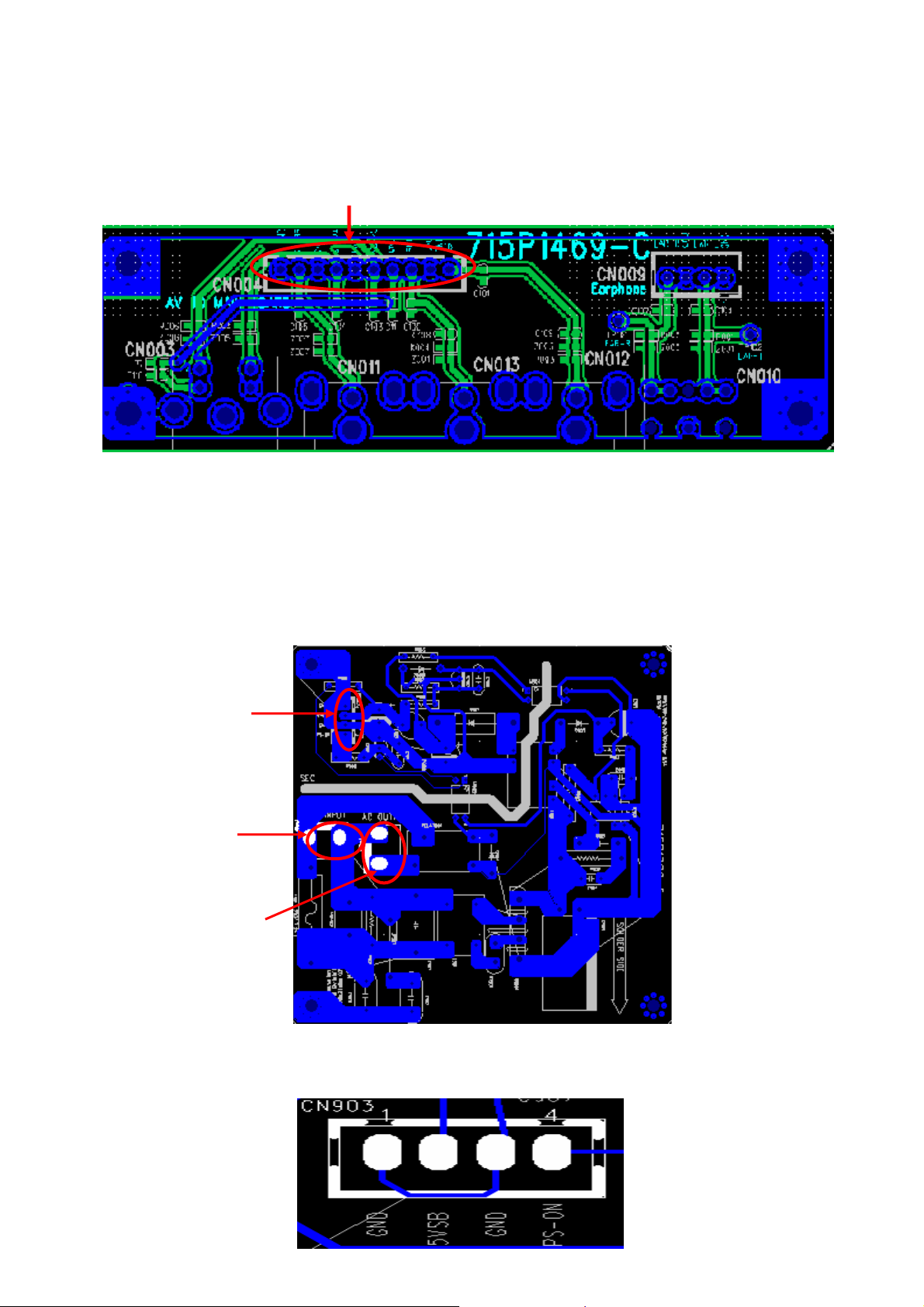
11-2 SIDE AV Board
The picture below is AV SIDE board, The interface pointed out in order to provides the power
for Audio board. The enlarged interface picture show in its connection.
CN004
Shown order connect power(it depends on to be 1 pin to 10 pin from left to right) according to
the picture:
11-3 PDC Board
The following picture show PDC Board, among them getting red difference label about
connection with PDC Board and main board, power board and switch of board.
CN901: Connect with P9Z1 of Power Switch Board;
CN902: Connect with CN8001 of Power Board;
CN903: Connect with CN706 of Imager Board.
CN903
CN901
CN902
The following picture shows the pin connection of CN903:
Page 45 of 83
Page 47

12、Mechanical Introduction
12-1 PDP Internal view
Page 46 of 83
Page 48

12-2 Mechanical of cabinet front disassembly
Page 47 of 83
Page 49

12-3 Disassembly and assembly
12-3-1 PDP stand removal
4) Unplug the AC power and all signal cables.
5) Place the PDP upside down on a tabletop (use a protection sheet or EPE bag), Take care, that this
is flat and free from obstacles like screws, to prevent damaging the fragile PDP glass filter (1).
6) Remove the four black colored screws around the stand holder (2).
7) Remove the Base assembly from PDP as the direction arrowhead showed (3).
3 2
Page 48 of 83
1
Page 50

12-3-2 Back Cover Removal
1) Remove the six big black colored screws in the panel holder as the red-circle showed (1).
2) Remove the seven black colored screws around the terminals as the green-pane showed (2).
3) Remove the eighteen black colored screws around the back cover as the blue-pane showed (3).
4) Carefully prize up the back cover from the left of the PDP (5).
5) Carefully remove the Back Cover from the
top of the PDP, and store in a safe place.
3
1
2
4
6) Done.
Page 49 of 83
Page 51

3
12-3-3 Rear Low Cover removal
1) Remove the three black screws in Rear low cover (1).
2) Carefully use a allen screwdriver to remove the six silver colored allen screws M3*6mm (2).
3) Remove the five black screws (3).
5
ZOOM-1 ZOOM-1
6
4
1
4) Remove the one silver screws and remove the
GND cable (4).
5) Disconnect the AC cable from AC FILTER
Board (5).
Page 50 of 83
2
6)Remove the Rear Low Cover as the
direction arrowhead showed (6).
7)Done.
Page 52

12-3-4 Main Board(MGPC) removal
1) Disconnect the all connectors(J42,CN706,J14,J603,CN703,CN704,J11,J30 and J6 form M
GPC(main board). See the above figure.
2) Remove the six silver screws from MGPC(main board)(1).
3) Remove the MGPC board from PCB plate. 4) Done.
1
PCB Plate
J6
1
Page 51 of 83
Page 53

)
C
12-3-5 PCB Plate Removal
1) Remove the two Cable Clips from the PCB Plate(1)(2).
2) Remove the six sliver screws(3).
3) Cut the cable tie(4), Note, please carefully cut it, don’t make the cable damage.
Remove the P
4
4
B Plate
1 2
3
Page 52 of 83
Page 54

)
12-3-6 Key Board Remove
1) Remove the Six silver screws(1) to disassemble the key board from the bezel.
12-3-7 Side AV Board Removal
1) Remove the two silver screws (1).
2) Remove the side cover from Side AV board(2)
3
3) Disconnect the CN004 and CN009 from Side AV board.
4
Remove the four silver screws (3).
2
CN004
1
CN009
3
Page 53 of 83
Page 55

12-3-8 PDC(power down control)Board Removal
Panel
stand
Panel Holder
ZOOM 1
2
1
1) Remove the four sliver screws (1) and remove the panel stand from panel holder as
the direction arrowed showed.
2) Remove the four silver flat screws (2).
3) Remove the two black screws (3)
4) Remove the two silver screws (4)
5) Remove the panel holder from PDP.
CN903
5
Page 54 of 83
CN901
CN902
ZOOM 2
2
3
4
6) Disconnect CN901,CN902 and CN903 from PDC
board.
7) Remove the four sliver screws (5), and remove
the PDC board.
Page 56

12-3-9 Panel Module Removal
1) Remove the eight silver flat screws around the two panel holder (1).
ZOOM 1 ZOOM 2
1 1
1
ZOOM 3 ZOOM 4
2) Remove all the aluminum foil around the panel (2), after assemble
the new panel, must re-affix the aluminum foil, if it’s broken
must change a new one, otherwise, the EMI can be affected.
emove th3) R e twelve silver screw around the PANEL corner (3).
2
the panel module and move it out form the front cover(Bezel),
and store in a safe place.
3
3
Panel Holder-1
Panel Holder-2
4
1
ift 4) Two people hold the panel holder 1 and 2 respectively, then upl
3
3
Page 55 of 83
Page 57

12-4 Block Wiring diagram
12-4-1 PDP boards block wiring diagram
Internal speaker
Internal speaker
Internal speaker
Internal speaker
Internal speaker
Left
Left
Left
Left
Left
Sub-PSU
Sub-PSU
Sub-PSU
Sub-PSUSub-PSU
PANEL Module
PANEL Module
PANEL Module
PANEL Module
Main PSU
Main PSU
Main PSU
Main PSUMain PSUMain PSUMain PSU
CN706
CN706
CN706
J42
J42
J42
J42
CN706
J14 J603
J14 J603
J14 J603
J14 J603
J6
J6
J6
J6
Power
Power
Power
Power
input
input
input
input
PDC B/d
PDC B/d
PDC B/d
PDC B/d
AC output
AC output
AC output
AC output
Internal speaker
Internal speaker
Internal speaker
Internal speaker
Internal speaker
Right
Right
Right
Right
Right
CN902CN903
CN902CN903
CN902CN903
CN902CN903
CN901
CN901
CN901
CN901
Power filter B/d
Power filter B/d
Power filter B/d
Power filter B/d
CN004
CN004
CN004
CN004
CN009
CN009
CN009
CN009
Side AV B/d
Side AV B/d
Side AV B/d
Side AV B/d
Image board
Image board
Image board
Image board
Image board
Image board
Image board
Image board
Image board
Image board
Key board
Key board
Key board
Key boardKey board
Page 56 of 83
J11
J11
J11
J11
J30
J30
J30
J30
CN703
CN703
CN703
CN703
CN704
CN704
CN704
CN704
AC in
AC in
AC in
AC in
Socket
Socket
Socket
Socket
AC input
AC input
AC input
AC input
output
output
output
output
input
input
input
input
AC swit ch B/d
AC swit ch B/d
AC swit ch B/d
AC swit ch B/d
Page 58

No. Pin Connection Name Pin function
J42 Connector(13 Pins):
Pin 1= GND Pin 2= +5VSB
Pin 3= IR Pin 4= ENTER
J42 to Key board
1
MGPC key control signal
output
Pin 5= LED-B Pin 6=LED-A
Pin 7=KEY6 Pin 8=CH+
Pin 9= CH- Pin 10=VOL+
Pin 11=VOL- Pin 12=MENU
Pin 13=TV video
CN706 Connector(4 Pins):
Pin 1,3= GND Pin 2=+5VSB
Pin 4=REL-SW
CN903 Connector(4 Pins):
Pin 1,3= GND Pin 2=+5VSB
CN706 to CN903
2
PDC board DC output, and
MGPC standby PDC power
control output
Pin 4=PS-ON
J14 to speaker MGPC audio signal output
3
J14 Connector (2 Pins+2 Pins):
LO+/COMLO- and RO+/COMRO-
J603 Connector(6 Pins):
J603 to Sub-PSU
4
MGPC audio circuit power
input
Pin 1,2=+12V Audio
Pin 3,4,6=GND
Pin 5 = NC
CN703 Connector(11 Pins):
Pin 1=NC Pin 2=STB5V
Pin 4=Relay-SW Pin 5=D12V
Pin 8,9=D3.3V Pin 11=D6V
CN703 to Sub-PSU
5
MGPC power input and
relay control output
Pin 3,6,7,10 =GND
CN704 Connector(5 Pins):
CN704 to Sub-PSU MGPC power input
6
Pin 1=D6V Pin 3=D12V
Pin 2,4=GND Pin 5=NC
J11 Connector(5 Pins):
J11 to CN004 To Earphone output
7
Pin 1,3=GND Pin 2=EAR-L
Pin 4 = EAR-R Pin 5=Phone-on
J30 Connector(10 Pins):
Pin 1,3,5,9=GND Pin 2=CVBS IN-2
J30 to CN009 Side AV signal input
8
Pin 4=FRONT-Y Pin 6=FRONT-C
Pin 7=FRONT-AV-SEL
Pin 8=SM-L Pin 10=SM-R
J6 LVDS connector(31 Pins):
Pin 1,8,9=NC
Pin 2,4,6,11,14,15,18,19,
J6 to Panel Logic
9
b/d
MGPC LVDS signal output
22,23,26,27,30,31=GND
Pin 12=TXE3p Pin 13=TXE3m
Pin 16=TXECp Pin 17=TXECm
Pin 20=TXE2p Pin 21=TXE2m
Pin 24=TXE1p Pin 25=TXE1m
Pin 28=TXE0p Pin 29=TXE0m
Page 57 of 83
Page 59

12-4-2 Panel Wiring diagram
Page 58 of 83
Page 60

13、Image board PCB LAYOUT
13-1 Image board PCB LAYOUT
13-2 Key board PCB LAYOUT
13-3 Side AV board PCB LAYOUT
13-4 PDC board PCB LAYOUT
Detail LAYOUT diagram please see the attached file “715P1511-G-4-17.pcb”.
715P1511-1C
Page 59 of 83
Page 61

14、Schematic diagram
Page 60 of 83
Page 62

Page 61 of 83
Page 63

Page 62 of 83
Page 64

Page 63 of 83
Page 65

Page 64 of 83
Page 66

Page 65 of 83
Page 67

Page 66 of 83
Page 68

Page 67 of 83
Page 69

Page 68 of 83
Page 70

Page 69 of 83
Page 71

Page 70 of 83
Page 72

Page 71 of 83
Page 73

Page 72 of 83
Page 74

Page 73 of 83
Page 75

Page 74 of 83
Page 76

Page 75 of 83
Page 77

Page 76 of 83
Page 78

Page 77 of 83
Page 79

Page 78 of 83
Page 80

Page 79 of 83
Page 81

Page 80 of 83
Page 82

Page 81 of 83
Page 83

Page 82 of 83
 Loading...