

Page 1
20" LCD TV Color Monitor LV20E351
Service
Service
Service
Horizontal Frequency
31.5-49kHz
TABLE OF CONTENTS
Description Page Description Page
Table Of Contents.......……..............................…........1
Revision List.…........................................……......2
Important Safety Notice.……..................……......3
1.Specification For LCD-TV……....................………........4
1.1 General Specification…………………………….......4
1.2 LCD-TV Description..…………...............…….........5
1.3 Interface Connector.........…...........…..…...........5
2. Precautions And Notices…............…................5
2.1 Assembly Precaution...........................…............5
2.2 Operating Precaution…............……………..........5
2.3 Storage Precaution….…........………..…...............5
2.4 High Voltage Warning…………….…….…………….5
3. Input/Output Specification…………………………….6
SAFETY NOTICE
4. Adjustments………….……..............................……….7
5. Trouble Shooting………………………………………..14
6.White-Balance, Luminance Adjustment……………….20
7.Block Diagram………..…....………..............................22
7.1 Main Board……….…...……………..………..............22
7.2 Power Board……………...….……………………..….23
8.Schematic………………..…....…..............................24
8.1 Main Board..…..……………......................................24
8.2 Power Board…….....…..……....................................37
9. Explode View…………………………………………….41
10. BOM List..…………..........………………….……......42
11.PCB Layout..…….……..........………………….…......67
11.1 Main Board.……….…………………….…… ...........67
11.2 Power Board.…..……………..………..…......….......69
ANY PERSON ATTEMPTING TO SERVICE THIS CHASSIS MUST FAMILIARIZE HIMSELF WITH THE
CHASSIS AND BE AWARE OF THE NECESSARY SAFETY PRECAUTIONS TO BE USED WHEN SERVICING
ELECTRONIC EQUIPMENT CONTAINING HIGH VOLTAGES.
CAUTION: USE A SEPARATE ISOLATION TRANSFOMER FOR THIS UNIT WHEN SERVICING
1
Page 2

Revision List
Revision Release Date Revision History TPV Model
A00 Jun-06-06 Initial Release EAB5ASNBC3VDTM
2
Page 3

Important Safety Notice
Proper service and repair is important to the safe, reliable operation of all AOC Company Equipment. The service
procedures recommended by AOC and described in this service manual are effective methods of performing service
operations. Some of these service operations require the use of tools specially designed for the purpose. The special
tools should be used when and as recommended.
It is important to note that this manual contains various CAUTIONS and NOTICES which should be carefully read in
order to minimize the risk of personal injury to service personnel. The possibility exists that improper service methods
may damage the equipment. It is also important to understand that these CAUTIONS and NOTICES ARE NOT
EXHAUSTIVE. AOC could not possibly know, evaluate and advise the service trade of all conceivable ways in which
service might be done or of the possible hazardous consequences of each way. Consequently, AOC has not
undertaken any such broad evaluation. Accordingly, a servicer who uses a service procedure or tool which is not
recommended by AOC must first satisfy himself thoroughly that neither his safety nor the safe operation of the
equipment will be jeopardized by the service method selected.
Hereafter throughout this manual, AOC Company will be referred to as AOC.
WARNING
Use of substitute replacement parts, which do not have the same, specified safety characteristics might create shock,
fire, or other hazards.
Under no circumstances should the original design be modified or altered without written permission from AOC. AOC
assumes no liability, express or implied, arising out of any unauthorized modification of design.
Servicer assumes all liability.
FOR PRODUCTS CONTAINING LASER:
DANGER-Invisible laser radiations when open AVOID DIRECT EXPOSURE TO BEAM.
CAUTION-Use of controls or adjustments or performance of procedures other than those specified herein may result
in hazardous radiation exposure.
CAUTION -The use of optical instruments with this product will increase eye hazard.
TO ENSURE THE CONTINUED RELIABILITY OF THIS PRODUCT, USE ONLY ORIGINAL MANUFACTURER'S
REPLACEMENT PARTS, WHICH ARE LISTED WITH THEIR PART NUMBERS IN THE PARTS LIST SECTION OF
THIS SERVICE MANUAL.
Take care during handling the LCD module with backlight unit
-Must mount the module using mounting holes arranged in four corners.
-Do not press on the panel, edge of the frame strongly or electric shock as this will result in damage to the screen.
-Do not scratch or press on the panel with any sharp objects, such as pencil or pen as this may result in damage to the
panel.
-Protect the module from the ESD as it may damage the electronic circuit (C-MOS).
-Make certain that treatment person’s body is grounded through wristband.
-Do not leave the module in high temperature and in areas of high humidity for a long time.
-Avoid contact with water as it may a short circuit within the module.
-If the surface of panel becomes dirty, please wipe it off with a soft material. (Cleaning with a dirty or rough cloth may
damage the panel.)
3
Page 4
1. Specifications For LCD TV
1-1 General Specifications
20.1” screen
Feature
SVGA ( 800 x 600 ) Resolution
High Brightness ( 500 cd/m
High Contrast Ration ( 500:1 )
Wide Viewing Angle ( 160 H / 160 V )
Built-in Full channel Tuner with Nicam, Teltext.
Graphic (VGA)
PIP(Video on Graphic)
2
)
Items
Screen Size 20.1” TFT-LCD Panel (AU)
Aspect Ratio 4:3
Resolution
Display Area (opening) H x V
Pixel Pitch
LCD Panel
TV Function
Graphic
(VGA)
Audio Output
Other
Function
OSD
language
Table Stand
Wall Mount
Power
Panel Tilt
Dimension
Weight (net) Kg (w/o Accessories) 9KG
Accessories
Video/Audio
Inputs
Display colors 16.7 million
Contrast Ratio 500:1
Brightness 500cd /m2
Viewing Angle
Response Time 16ms
Lamp Type/Life 60000 hr
Color Temperature Cold/Warm
TV Tuning System
Sound System Nicam / A2
Tel te x t Ye s
Color systems PAL / SECAM / NTSC
Signal Input Analog: D-Sub 15 pin (detachable cable)
PnP compatibility DDC / 2B
Input frequency
Recommended Analog: 800 x 600 (60Hz)
Input Audio Headphone Mini-jack for stereo (3.5ø)
Audio Output: L / R
PIP, Wireless Headphone (Option), DPF -Digital Photo Frame (Option)
English/Italian/Spaish/German/French/ Portuguese
Included
VESA 100 x 100 mm
Power Supply AC100V~240V, 50/60Hz
Power Consumption <70W
Forwards/Backwards/ Rotation
W x H x D (with stand) 696 x 443 x 250 (mm)
Remote Controller, Batteries (x2), AC Power Cord, User Manual
SCART
RCA
S-Video
Specification
800 × 600 (SVGA)
408mm × 306mm
0.51mm × 0.51mm
160°(Horizontal) / 160°(Vertical)
PAL B/G, D/K, I and SECAM L/L’ (Multi-Europe)
Full Channel with Electronic PLL Tuner
Analog: FH: 31.5KHz to 48KHz
FV: 56Hz to 75Hz
Speaker (built-in): Two 2 watt speakers
Headphone Mini-jack for stereo (3.5ø)
Line Output (RCA L/R)
-5°/ +20°/ ± 30°
RGB or CVBS ×1 Audio L/R ×1
CVBS (Composite) ×1 Audio L/R ×1
S-Video×1
Share with CVBS
(RCA)
4
Page 5

1-2 LCD TV Description
The LCD TV will contain a main board (include audio), a switching power board (include an inverter board), an
IR board, a function keyboard, and an Earphone board. The main board and power board will house the flat
panel to control logic I2C bus, DDC, brightness control logic for LCD panel, DC-DC conversion to supply the
appropriate power to the whole board and transmitting TTL level signals into LCD Module to drive the LCD
display circuit.
The inverter board will drive the six CCFLs (Cold Cathode Fluorescent Tube).
The switching power board will provides the power ON/OFF to control the TV and control LED indicator for
DPMS.
The function keyboard and Remote Control will provide the OSD control signal to the Main Board.
1-3 Interface Connector
(A) Power Cord Connector.
(B) RF Signal Connector.
(C) Video (SCART, AV2, S-VIDEO) / Audio Signal Connectors.
(D) PC D-sub 15 pin Connector.
(E) PC Audio Connector.
2. Precautions And Notices
2-1 Assembly Precaution
(1) Please do not press or scratch LCD panel surface with anything hard. And do not soil LCD panel surface by
touching with bare hands (Polarize film, surface of LCD panel is easy to be flawed)
In the LCD panel, the gap between two glass plates is kept perfectly even to maintain display characteristic
and reliability. If this panel is subject to hard pressing, the following occurs:
(a) Uniform color (b) Orientation of liquid crystal becomes disorder
(2) Please wipe out LCD panel surface with absorbent cotton or soft cloth in case of it being soiled.
(3) Please wipe out drops of adhesive like saliva and water in LCD panel surface immediately.
They might damage to cause panel surface variation and color change.
(4) Do not apply any strong mechanical shock to the LCD panel.
2-2 Operating Precaution
(1) Please be sure to unplug the power cord before remove the back-cover. (be sure the power is turn-off)
(2) Please do not change variable resistance settings in MAIN-BOARD; they are adjusted to the most suitable
value. If they are changed, it might happen LUMINANCE does not satisfy the white balance spec.
(3) Please consider that LCD backlight takes longer time to become stable of radiation characteristic in low
temperature than in room temperature.
(4) Please pay attention to displaying the same pattern for very long-time. Image might stick on LCD.
2-3 Storage Precaution
(1) When you store LCD for a long time, it is recommended to keep the temperature between 0℃-40℃ without
the exposure of sunlight and to keep the humidity less than 85% RH.
(2) Please do not leave the LCD in the environment of high humidity and high temperature such as 60℃,
85%RH.
(3) Please do not leave the LCD in the environment of low temperature; below -25°C.
2-4 High Voltage Warning
The high voltage was only generated by INVERTER module on Power Board, if carelessly contacted the
transformer on this module, can cause a serious shock. (the lamp voltage after stable around 600V, with lamp
current around 8mA, and the lamp starting voltage was around 1500V, at Ta=25°C)
5
Page 6
3. Input/Output Specification
This procedure gives you instructions for installing and using the LCD TV display.
1. Position the display on the desired operation and plug the power cord into a convenient AC outlet. Three-wire power
cord must be shielded and is provided as a safety precaution as it connects the chassis and cabinet to the electrical
conduct ground. If the AC outlet in your location does not have provisions for the grounded type plug, the installer
should attach the proper adapter to ensure a safe ground potential.
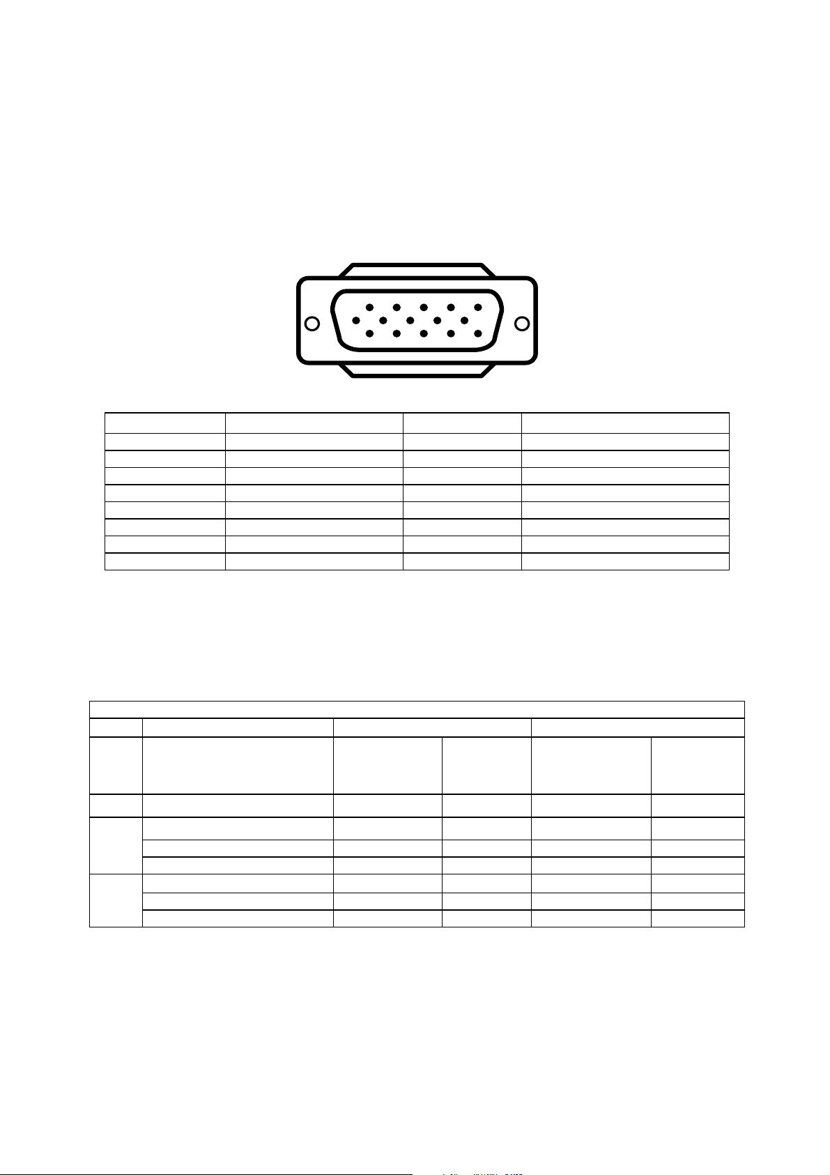
2. Connect the 15-pin color display shielded signal cable to your signal system device and lock both
screws on the connector to ensure firm grounding. The connector information is as follow:
Pin No. Description Pin No. Description
1. RED Video 9. NC
2. GREEN Video 10. Sync Ground
3. BLUE Video 11. RXD (for ISP)
4. TXD (for ISP) 12. Serial Data for DDC
5. Ground 13. HORIZ. SYNC
6. Ground-R 14. VERT. SYNC
7. Ground-G 15. Serial Clock for DDC
8. Ground-B
Factory Preset Display Modes:
Analog RGB Signal Timing
Horizontal Vertical
Mode Resolution
1
6
11 15
5
10
15 - Pin Color Display Signal Cable
VESA MODES
Nominal
Frequency
Sync
Polarity
(KHz)
Nominal
Freq.
(Hz)
Sync
Polarity
DOS
720x400@70Hz 31.5 N 70.1 N
640x480@60Hz 31.469 N 59.940 N
640x480@72Hz 37.861 N 72.809 N
640x480@75Hz 37.500 N 75.00 N
800x600@60Hz 37.879 P 60.317 P
800x600@72Hz 48.077 P 72.188 P
800x600@75Hz 46.875 P 75.000 P
6
Page 7

4. Adjustment
4-1 Adjustment Control Function
Adjustments items as below:
External Controls: (7-key knob) Menu, CH Down, CH Up, Power On/Off, VOL Down, VOL Up, Source
OSD Control function:
To Use The Menus
TO USE THE MENUS
1. Press the MENU button repeatedly to display each menu.
2. Use the cursor up/down to select a menu item or adjust the setting of Menu item.
3. Use the cursor left/right to enter a submenu or enable the function.
4. Press the MENU button to exit the menu.
MAIN MENU
Press the MENU button into the main OSD (On Screen Display). Adjust item include VIDEO, AUDIO, TV (only in the
TV mode), PC and PIP (only in the PC mode) and SETUP.
1. CONTRAST, BRIGHTNESS, COLOUR and TINT are adjusted from 0 to 100.
2. BLACK LEVEL is adjusted from 0 to 100.
3. SHARPNESS is adjusted from -5 to+5.
You can adjust picture contrast, brightness, color, tint and sharpness to the levels you prefer.
4. RESET is set up to default value.
VIDEO Adjust
7
Page 8

Note: TINT only work in NTSC video signal input.
When adjust any item sub-OSD will show up like this.
AUDIO Adjust
1. VOLUME is adjusted from 0 to 100.
2. BASS and TREBLE are adjusted from 0 to 100.
You can adjust picture Volume, Bass and Treble to the levels you prefer.
When adjust any item sub-OSD will show up like this.
3. SRS for turn on / off SRS function. SRS is audio technology makes everything sound better.
TV
Quick Installation
1. Use COUNTRY to select your country first.
2. Move to SCAN and scan the program.
3. After scan finished, user can use SKIP to skip the unlike program.
PROGRAM Editing
Using PROGRAM, FREQENCY, SWAP, and INSERT for program edit.
1. Move to PROGRAM, select the program you want to edit
2. Move to FREQENCY, use RIGHT or LEFT button for program search.
3. User can use SWAP for program swap.
8
Page 9
4. Use INSERT to insert current program into selected position.
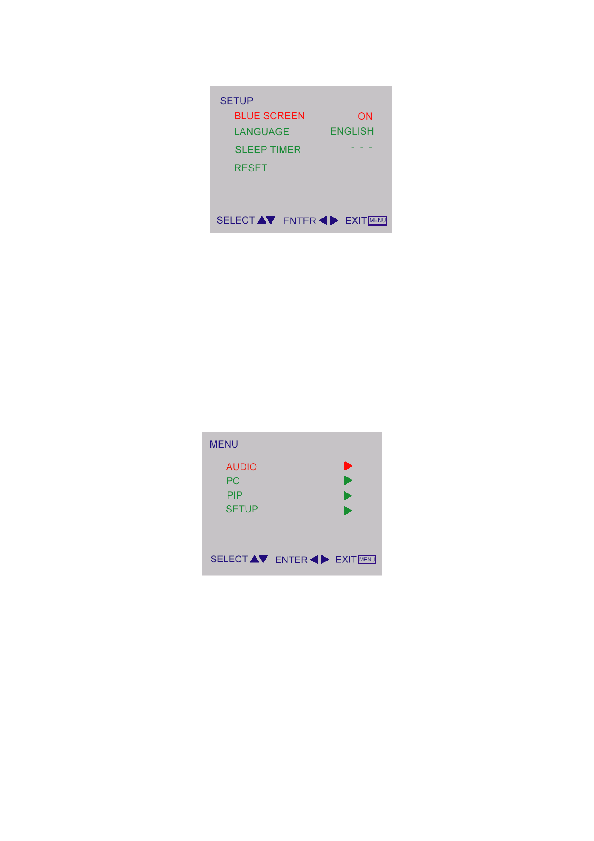
SETUP
1. BLUE SCREEN for when no video input screen will be blue or blank. If it’s ON, the screen will be in blue. If it’s OFF,
the screen will be blank. Preset is ON.
1. LANGUAGE for different language OSD MENU. Preset is English.
2. SLEEP TIMER is for set a time period after which the TV should switch itself to standby. The counter runs from 0 >
30 > 60 > 90 > 120 minutes.
3. RESET is set up to default value of BLUE SCREEN and SLEEP TIMER.
Note: To view the remaining time, press the SLEEP button once. To cancel the sleep time, repeatedly press the
SLEEP button until… APPEARS. If you turn the TV off after setting the sleep time, the setting will be erased. Set it
again.
PC Setup
9
Page 10
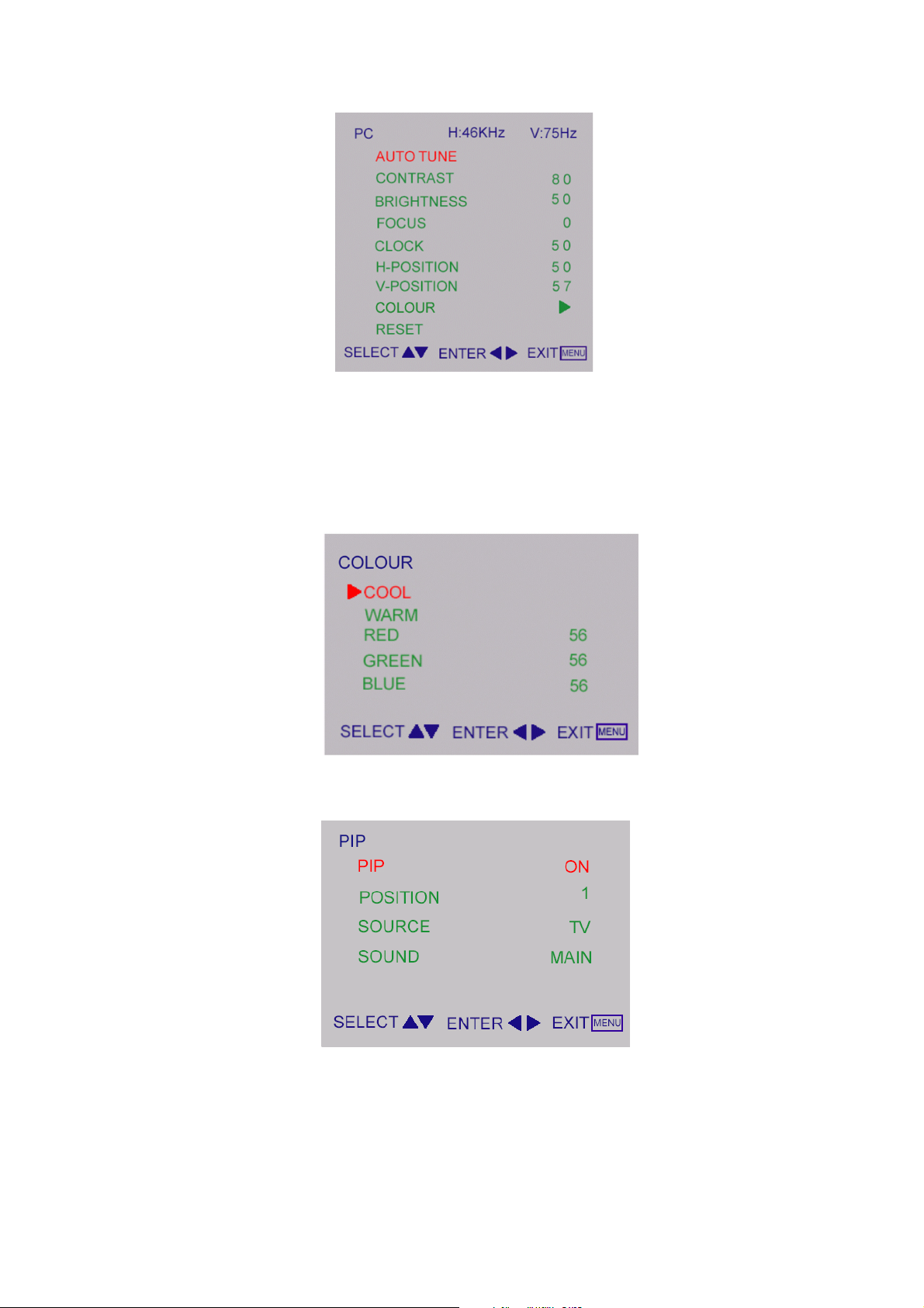
PC Adjust
1. AUTO TUNE is the function auto-sizing for VGA input.
2. CONTRAST, BRIGHTNESS, FOCUS, CLOCK, H-POSITION, V-POSITION and COLOUR are the functions for
PC adjustment.
Colour for you can adjust the colour temperature you prefer.
COLOUR
PIP
PIP
1. PIP for turn on / off small picture function.
2. POSITION for change the position of small picture.
3. SOURCE for select video source of small picture.
4. SOUND for select audio source form MAIN (PC) or SUB (Video).
Input Source Select:
Press repeatedly Source button to select TV, AV1, SCART, S-VIDEO or PC mode.
10
Page 11
V
p
2
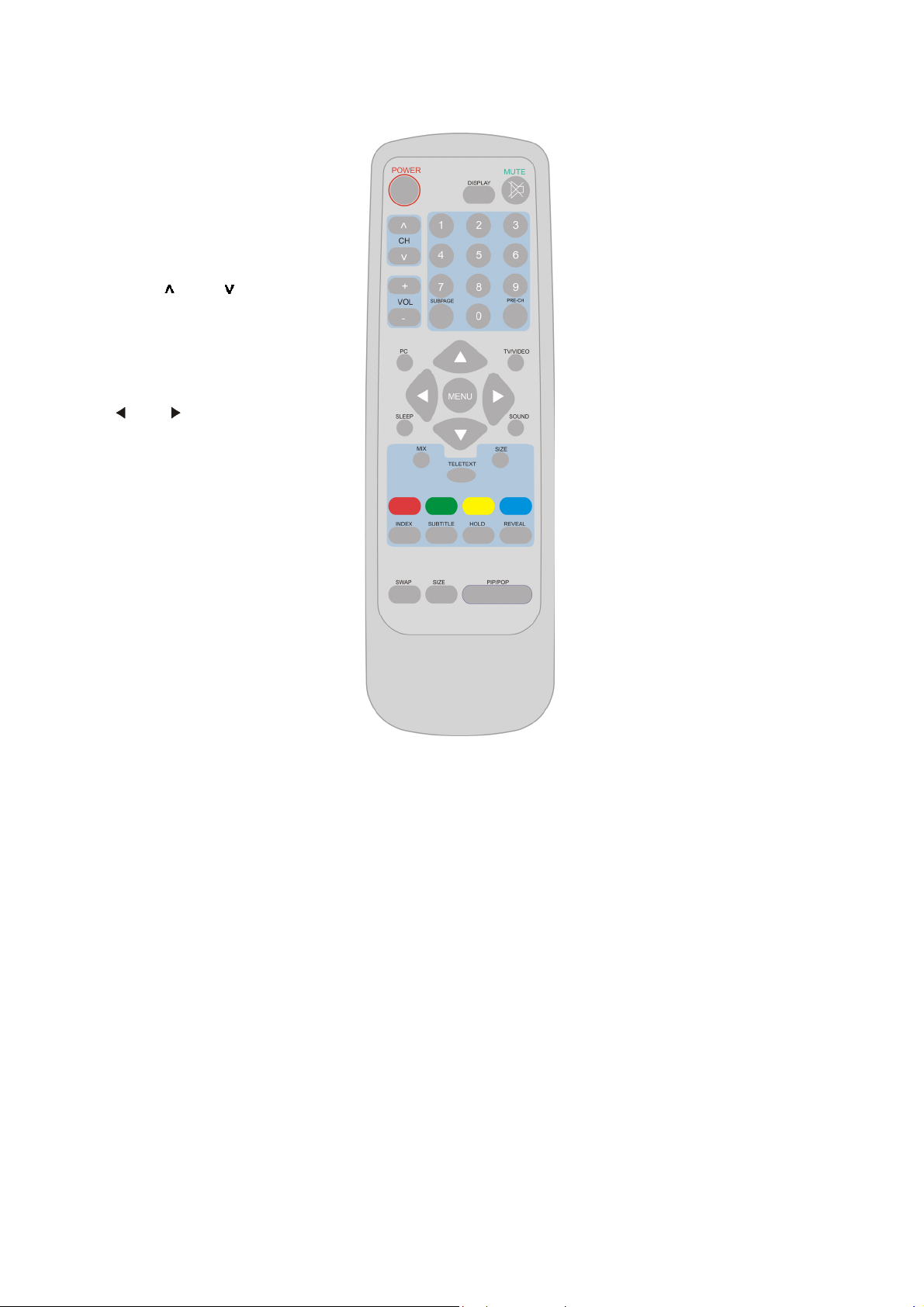
Use of the remote control
USE OF THE REMOT CONTROL
TELE
POWER:
Press to turn on/off the TV.
The TV is never completely
powered off unless it is
physically unplugged.
CH
Press or (or
MENU ▲ or ▼
button) to brows through
the TV channels which
OL
Press + or – (or MENU
or button) to
PC
Select your input
source to PC.
SLEEP
With this key you can set a
time period after which the
TV should switch itself to
standby. Press the key
repeatedly to select the
number of minutes. The
counter runs from
0,30,60,90,120 minutes.
The timer begins to count
down from the number of
minutes selected after the
display has disappeared.
1
SWAP
Press to swap the two
screens when PIP is work
(option).
MENU Press repeatedly
to display OSD menu.
SIZE
Includes 3 modes. Press
repeatedly to select 4:3: to
16:9 (Linear) / 4:3 to 16:9
(non-Linear) /16:9 (option).
DISPLAY
(1) Display Channel number
when use RF input.
(2) Display input source when
use other input except TV
RF in
ut.
MUTE
Temporarily interrupt the
sound or restore it.
SUBPAGE
Teletext Subpage function.
0~9 DIGIT BUTTONS
To select a TV channel.
PRE-CH
To display the previously
selected TV channel.
TV/VIDEO
Select your input source:
press repeatedly to select TV,
AV, S-VIDEO or SCART
mode, according to where you
connected your external
source.
SOUND
To select Mono/ Stereo /Dual
from TV RF input.
PIP/POP
Press to enable the screen of
Video on Graphic (option).
11
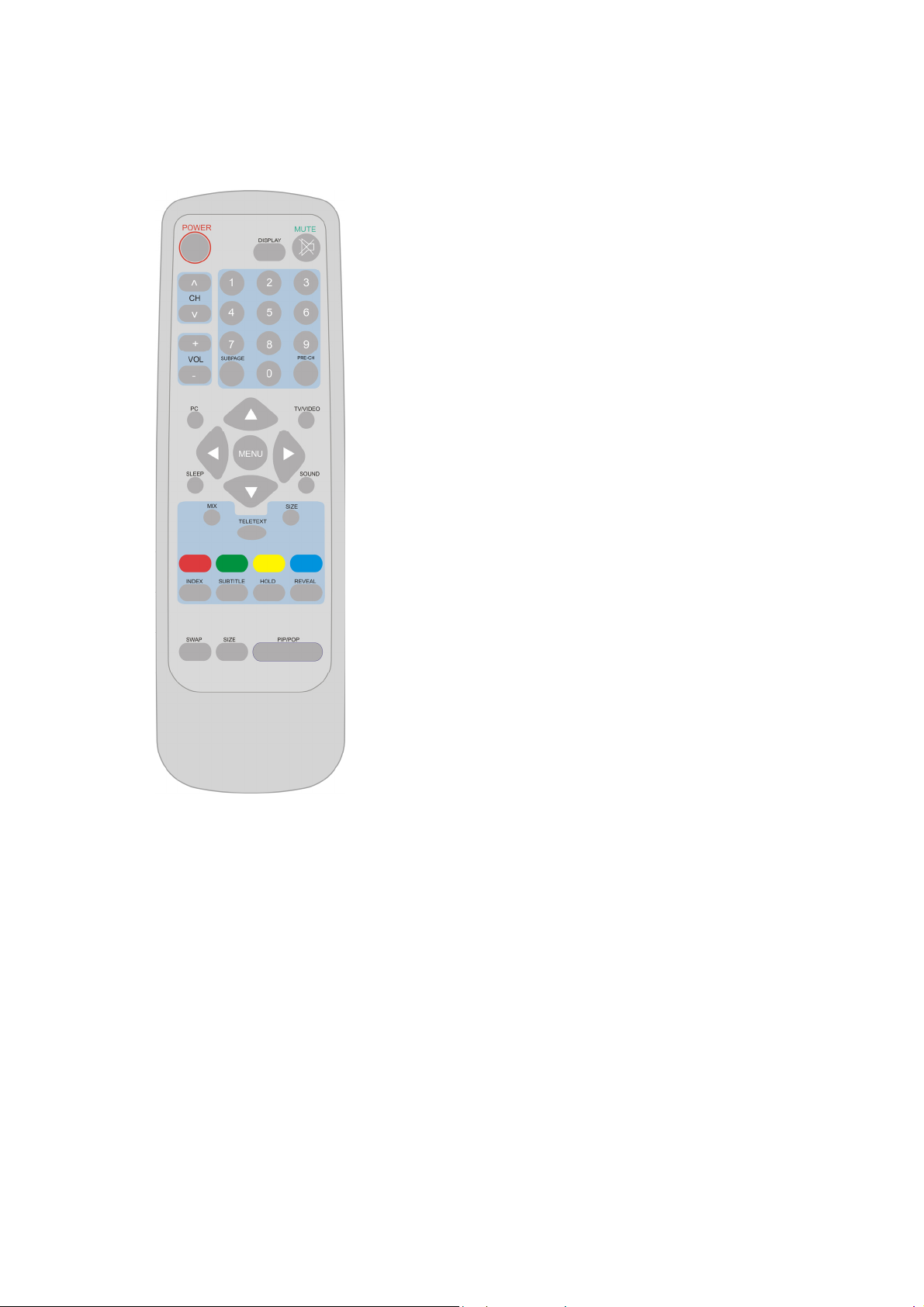
Page 12
y
TELETEXT
Teletext is an information service organized like a magazine, which is provided by some TV stations in addition to
regular television broadcasting.
TELETEXT
Press TELETEXT. The Teletext screen appears.
To turn off the Teletext mode, press TELETEXT
again.
MIX
Press MIX to superimpose the teletext over a
normal broadcast picture. Press again to
return to Teletext mode.
SIZE
Press SIZE repeatedly to display the upper
teletext part, the lower teletext part and then to
return to the normal.
Red / Green / Yellow / Blue
Use the COLORED BUTTONS to operate the
Teletext screen.
INDEX
Press INDEX to return to the main index page.
SUBTITLE
Press to select the next page marked as a
subtitle page and request it as the display p
age.
HOLD
Press HOLD to hold the Teletext page when
viewing information. Press again to return to
automatic page update.
REVEAL
Press REVEAL to display reveal hidden words
e.g. quiz page answers. Press again to hide.
Page selection
Page can be selected in two ways.
a. Press ▼or ▲ to increase or decrease the page number by one.
b. B
entering the page number, using digit buttons 0~9.
Subpage Access
When Teletext information exceeds more than on page. Press SUBPAGE
first then select the required page number using digit buttons 0~9.
12
Page 13

4-2 Adjustment Method
Press MENU key to show OSD window or exit, Up / Down key to done the function selection,
And + / - key to done the adjustment.
4-3 Front Panel Control Knobs
Power Key: Press to turn on or off the TV.
MENU Key:Press to show the OSD menu and exit OSD menu at the TV.
CH Down / Up Key:Press to perform select function and channel.
VOL - / + Key:Press to confirm your function selection and adjustment.
Source Key:Press to select your input source.
13
Page 14
,
)
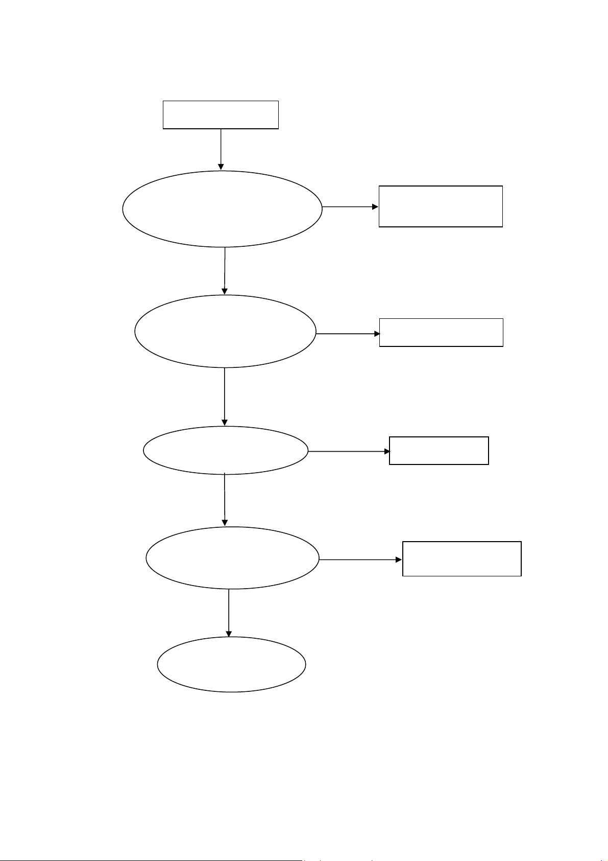
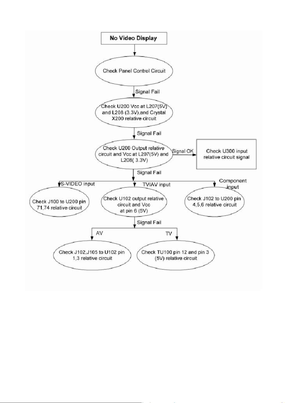
5. Trouble Shooting
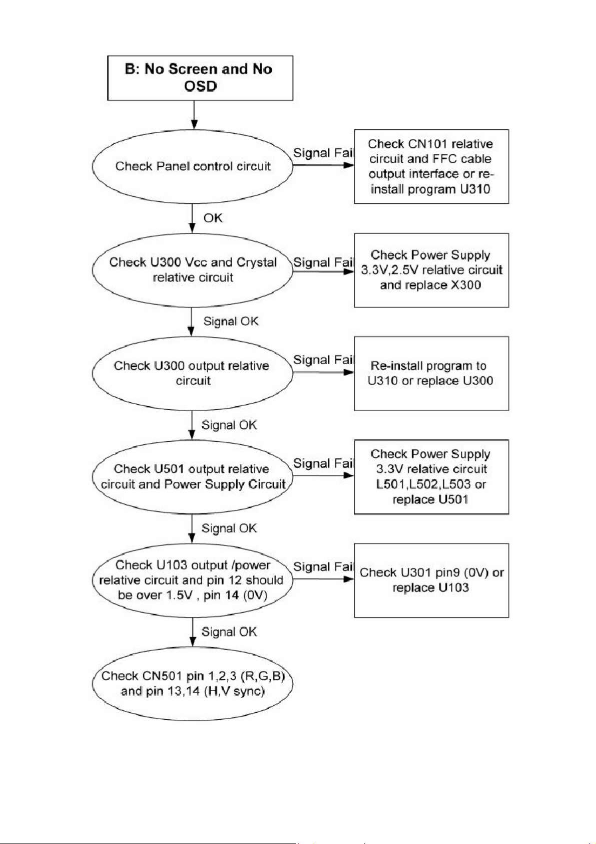
5-1 Panel Control Circuit
No Display
Check CN101 pin 42-45
is 5V and signal on pin
35,37,39,40,25-28,30-33,1518,20-23,5-8,10-13
NG
Check U300 Output to
CN101 relative circuit and
CN101 VCC at Q300,
Q301
NG
Check U300 crystal
X300 (12MHZ)
L309 (5V
OK
OK
Replace panel or FFC
cable to panel
Replace L118, C137
OK
Replace X300
NG
Check 2.5V L301-L304
33..33VV LL330055--LL330088
NG
Replace U300
OK
Replace components
if it has problem
14
Page 15
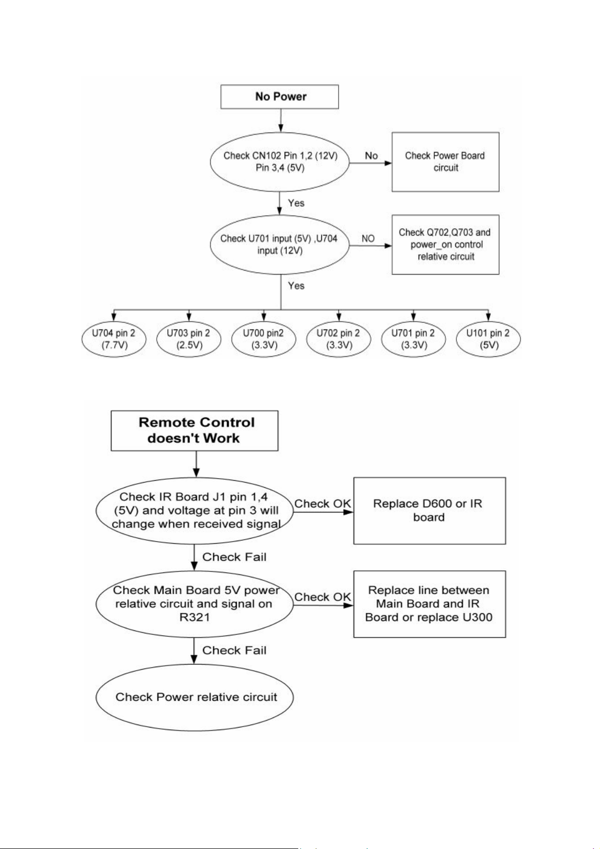
5-2. Main Board Power Circuit
5-3. Remote Control Block
15
Page 16
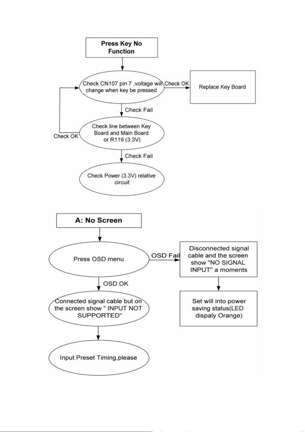
5-4. Key Board Control Block
5-5. Pc Control Block
16
Page 17
17
Page 18
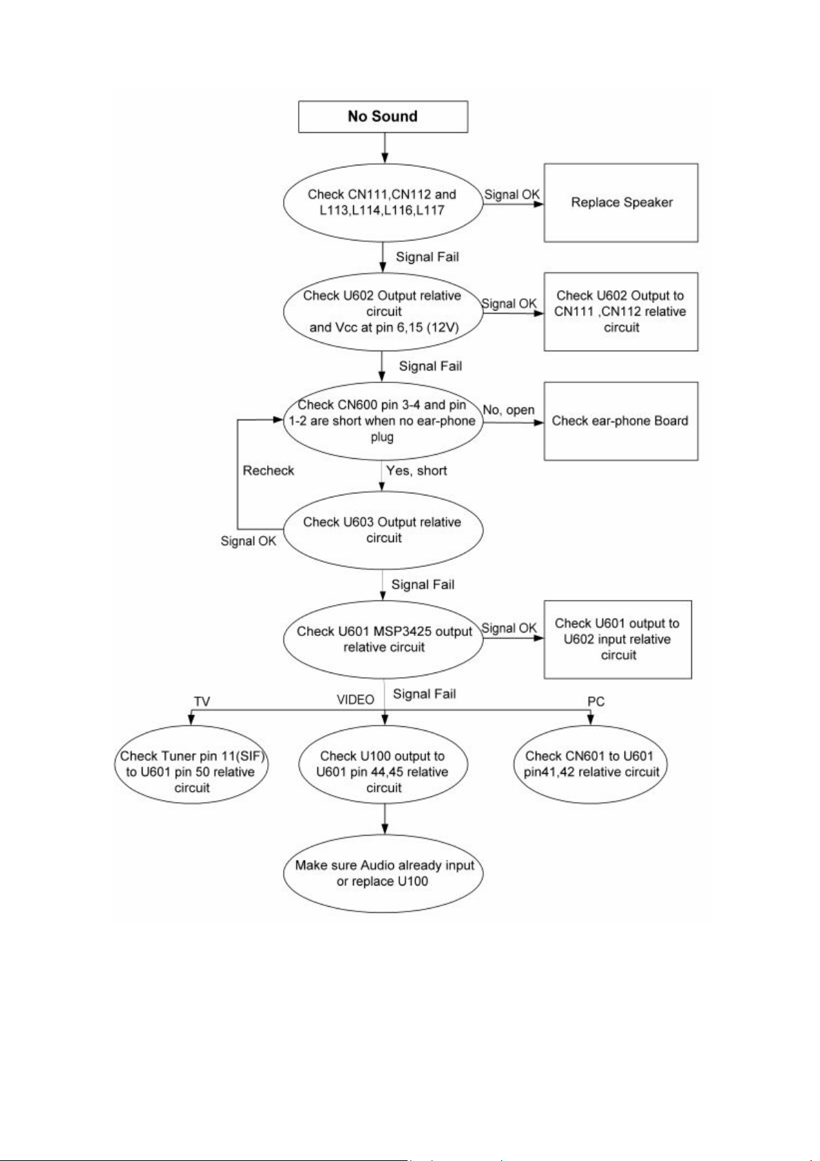
5-6. Audio Control Block
18
Page 19
5-7 Video Control Block
Note: 1、If Replace “MAIN-BOARD” , Please re-do “DDC-content” programmed & “WHITE-Balance”.
2、If Replace “ POWER-BOARD INVERTER” only, Please re-do “ WHITE-Balance”
3、Please re-install program before you do change any component.
19
Page 20

6. White-Balance, Luminance Adjustment
Approximately 30 minutes should be allowed for warm up before proceeding white
balance adjustment.
Before started adjust white balance, please setting the Chroma-7120 MEM. Channel 1 to 9300 colors, MEM.
Channel 2 to 6500 color, and MEM. Channel 3 to 9300 colors, (9300 parameter is x = 283 ± 15, y = 297 ± 15, Y =
SPC. ± 7 cd/m2; 6500 parameter is x = 313 ± 15, y = 329 ± 15, Y = SPC.± 7 cd/m
PC PC AV
Color Temp. 9300 6500 9300
x 0.283 0.313 0.283
y 0.297 0.329 0.297
Y
250±7 250±7 290±20
How to setting MEM.channel you can reference to Chroma-7120 user guide or simple use “ SC” key and “ NEXT”
key to modify x,y,Y value and use “ID” key to modify the TEXT description
Following is the procedure to do white-balance adjust
˙Press Number key 100 Æ 9 Æ 9 Æ 9 will into the factory mode, and press Menu key the OSD will show menu and a
word F at Right top of Menu.
˙In the factory mode select MORE function will into Bias and Gain adjustment.
1. ADC Adjustment:
AL Æ Auto level adjust.
RG, GG, BG Æ R, G, B Gain adjusts.
RB, GB, BB Æ R, G, B Bias adjusts.
2. SCALER Adjustment:
CO, BR Æ Contrast and Brightness adjust.
RG, GG, BG Æ R, G, B Gain adjusts.
RB, GB, BB Æ R, G, B Bias adjusts.
S9, S6, ST, SH Æ Save 9300, 6500, 9300 color temperature.
R9, R6, RT, RHÆ Recall 9300, 6500, 9300-color temperature.
BI Æ Setup Burn-in mode ON / OFF.
ISP ÆSet ISP ON/OFF.
PP Æ Set PIP ON/OFF.
WH Æ Set Wireless Headphone ON/OFF.
SR Æ Set SRS ON/OFF.
CC Æ Set Close Caption ON/OFF.
VC Æ Set V Chip ON/OFF.
EX Æ Exit MORE function to factory mode menu.
II. Bias (Low luminance) adjustment:
1. Press “ AUTO” button,
2. Set the contrast on OSD window to the value=51, color (user) R, G, B set to “50”
3. Adjust the brightness on OSD until chroma 7120 measurement reach the value Y>390 cd/m
III. Gain adjustment:
A. Adjust 9300 color-temperature:
1. Set the Contrast of OSD function to 45 and Adjust Brightness to chroma-7120 Y>230 cd/m
2. Switch the chroma-7120 to RGB-mode (with press “MODE” button)
3. Switch the MEM.channel to Channel 01 (with up or down arrow on chroma-7120)
4. The lcd-indicator on chroma-7120 will show x = 283 ± 15, y = 297 ± 15, Y =250 ± 7 cd/m
5. Adjust the Color(user)Mode: RED on OSD window, until chroma 7120 indicator reached the value R=100
6. Adjust the Color (user) Mode: GREEN on OSD window, until chroma-7120 indicator reached the value
G=100
7. Adjust the Color (user) Mode: BLUE on OSD window, until chroma-7120 indicator reached the value B=100
8. Repeat above procedure (Item 5,6,7) until chroma-7120 RGB value meet the tolerance =100±2
9. Switch the chroma-7120 to xyY mode With press “MODE” button
10. Press Color (9300) on OSD window to save the adjustment result
B.Adjust 6500 color-temperature:
20
2
)
2
2
2
Page 21

1. Set the Contrast of OSD function to 45 and Adjust Brightness to chroma-7120 Y>230 cd/m
2. Switch the chroma-7120 to RGB-mode (with press “MODE” button)
3. Switch the MEM.channel to Channel 02 (with up or down arrow on chroma-7120)
4. The lcd-indicator on chroma-7120 will show x = 313 ± 15, y = 329 ± 15, Y = 250 ± 7 cd/m
5. Adjust the Color (user) Mode: RED on OSD window, until chroma 7120 indicator reached the value R=100
6. Adjust the Color (user) Mode: GREEN on OSD window, until chroma-7120 indicator reached the value G=100
7. Adjust the Color (user) Mode: BLUE on OSD window, until chroma-7120 indicator reached the value B=100
8. Repeat above procedure (item 5,6,7) until chroma-7120 RGB value meet the tolerance =100 ± 2
9. Switch the chroma-7120 to xyY mode with press “MODE” button
10.Press Color (6500) on OSD window to save the adjustment result
C. Adjust 9300 color-temperature:
1. Set the Contrast of OSD function to 45 and Adjust Brightness to chroma-7120 Y>280 cd/m
2. Switch the chroma-7120 to RGB-mode (with press “MODE” button)
3. Switch the MEM.channel to Channel 03 (with up or down arrow on chroma-7120)
4. The lcd-indicator on chroma-7120 will show x = 283 ± 15, y = 297 ± 15, Y = 290 ± 20 cd/m
5. Adjust the Color (user) Mode: RED on OSD window, until chroma 7120 indicator reached the value R=100
6. Adjust the Color (user) Mode: GREEN on OSD window, until chroma-7120 indicator reached the value G=100
7. Adjust the Color (user) Mode: BLUE on OSD window, until chroma-7120 indicator reached the value B=100
8. Repeat above procedure (item 5,6,7) until chroma-7120 RGB value meet the tolerance =100 ± 2
9. Switch the chroma-7120 to xyY mode with press “MODE” button
10. Press Color (9300) on OSD window to save the adjustment result
Turn the POWER-button off to on to quit from factory mode (in USER-mode, the OSD window location was
placed at middle of screen)
2
2
2
2
21
Page 22
A
A
A
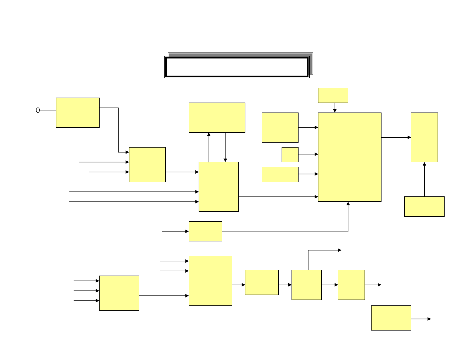
7. Block Diagram
7-1 Main Board
20” LCD TV Block Diagram
NT
VIDEO 1
SCART CVBS
S-VIDEO
CVBS
udio 1
SCART
DVD
Tuner
FQ1216ME/I
H-5(SV22)
74HC4052
D
NJM-2244
M-TE1/JR
C
PC
D-SUB
TV
PC
SAA5361HL/M1/1
651 FQFP-100
VPC 3230
Decoder
AD 9883
ADC
MSP3455
AUDIO
decoder
SRS
M62438
FP
E-Frame
Input
option
IR
Key PAD
PT2308
EAR
AMP
DRAM
SPV302A
PBGA-388
SUNPLUS
Scaler
OSD
MCU
Head phone
udio
AMP
TDA7
266D
Panel
Inverter
Speaker (2W x 2)
AC 110/220V
22
Adapter
70W
12V/5V
Page 23
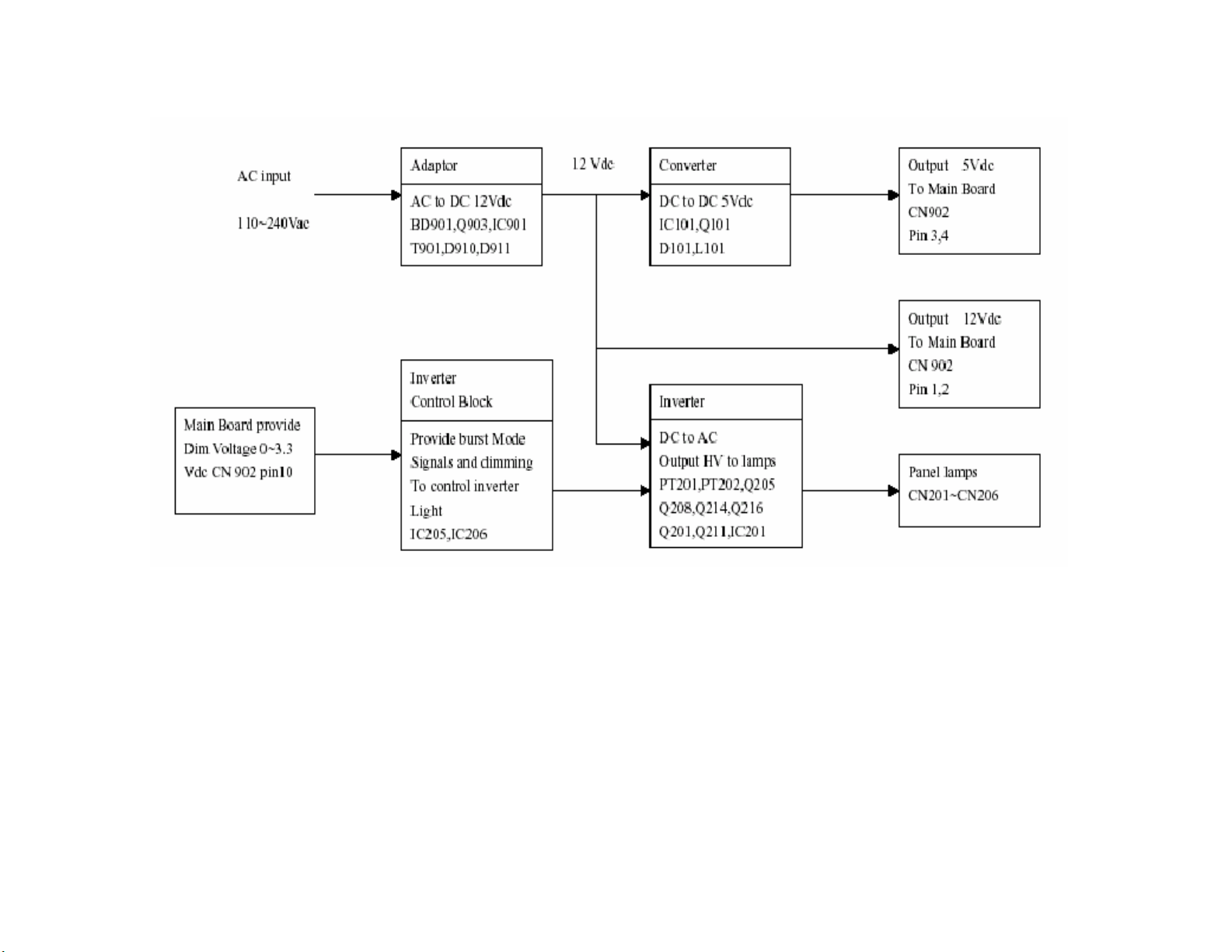
7-2 Power Board
23
Page 24
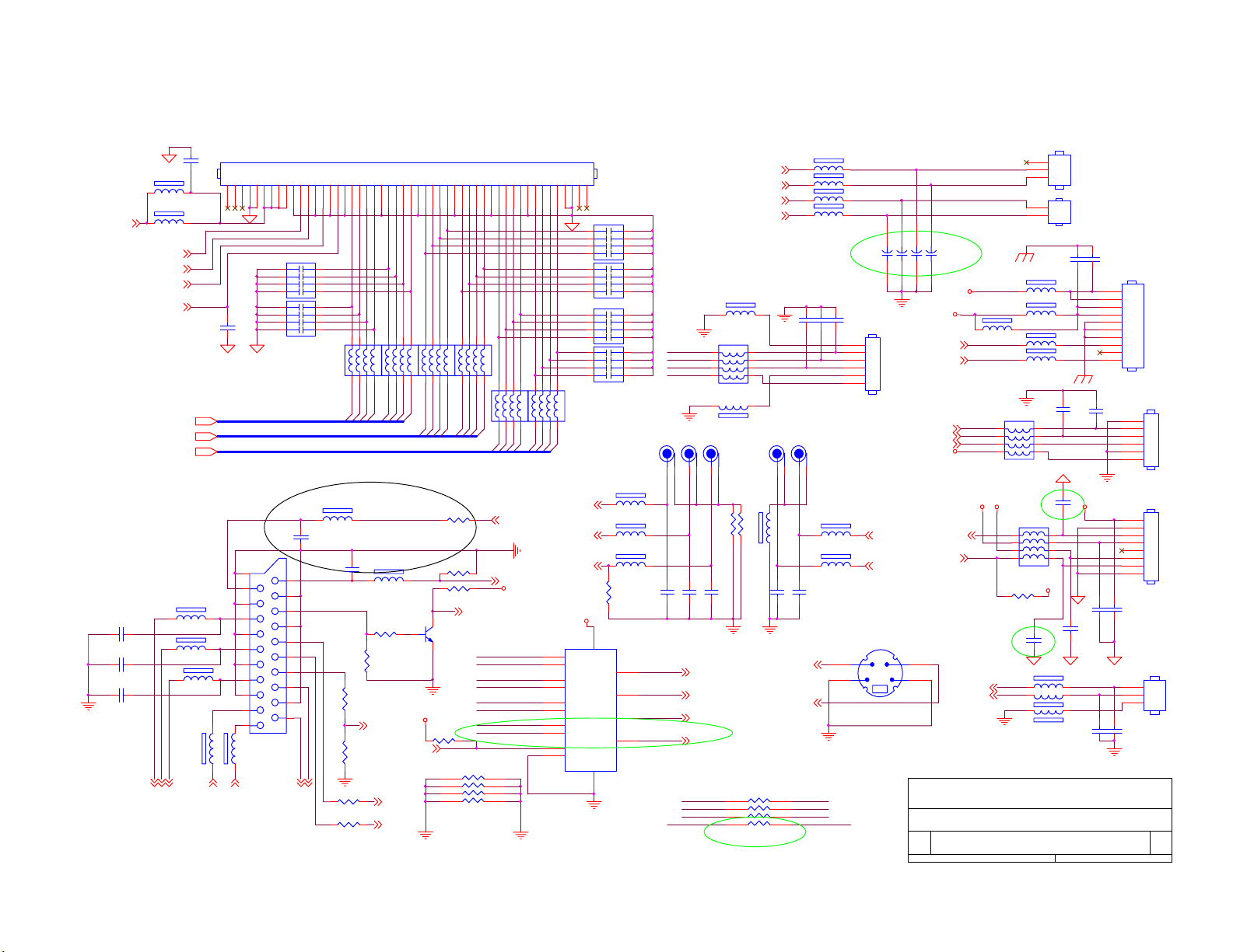
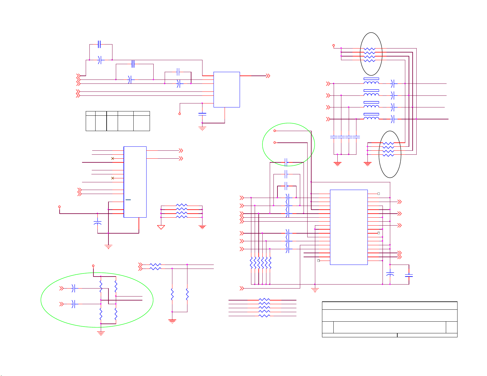
8. Schematic Diagram
8.1 Main Board
C137
0.1uF
L115
150 OHM
EMI
L118
150 OHM
PAN_PWR5,13
P_Hs6,13
P_Vs6,13
P_DATAEN6,13
P_CLK6, 13
R[0..7]6,13
G[0.. 7]6,13
B[0.. 7]6, 13
88L 35521A H
C157
68pF
68pF
68pF
C158
C159
O_PRO_PR
O_PRO_Y
O_PRO_PB
SCART _VG
SCART _VR
L139 150 OHM
L141 150 OHM
SCART _VB
L142 150 OHM
L126600 OHM
L127600 OHM
2
2
LINE_O_L
50
C130
22pF
65V1206391 32
J102
21
19
17
15
13
11
9
7
5
3
1
SCART
2
LINE_O_R
CP103 22pF
1
2
3
4 5
1
2
3
4 5
NC
390pF
11
8
7
6
8
7
6
LP100
150 OHM(8P4R)
L121
C134
20
18
16
14
12
10
8
6
4
2
11
R135 NC
SCART _AL
SCART _AR
R371 NC
CP105
22pF
150 OHM
NC
C151
100pF
123
R7
R6
R118
8.2K 1/16W
R100
1.8K 1/16W
2
CN101
LP101
150 OHM(8P4R )
678
678
4 5
R4
R5
C134 C135 BOM:NC 11/21
L138 150 OHM
R130
R123
SCART_SW2 5
2
123
4 5
R2
R1
R0
R3
75 1/16W
1
75 1/8W
5V
COMP_SEL5
SCART_H 2
SCART_V 2
AGND
123
G7
G6
75 1/16W
R121 1K 1/16W
32
NC
10K 1/16W
LP102
150 OHM(8P4R )
678
4 5
G4
G5
R117
75 1/16W
R133
Q100
PMBS3904
R138
1
2
3
4
LP103
150 OHM(8P4R )
678
123
4 5
G2
G0
G3
G1
123
B7
NC
VD_VOUT1 8
SCART_CVBS 2,9
SCART_SW1 5
O_PRO_Y
I_DVD_Y
O_PRO_PB
I_DVD_PB
O_PRO_PR
I_DVD_PR
SCART_CVBS
I_DVD_Y
RN106
8
7
6
5
LP104
678
B6
B5
5V
150 OHM(8P4R)
123
4 5
B3
B2
B4
12345678910111213141516171819202122232425262728293031323334353637383940414243444546474849
CP102
22pF
6
7
8
CP104
22pF
6
7
8
CP106
22pF
6
7
8
CP107
22pF
6
7
8
678
LP105
150 OHM(8P4R)
4 5
B1
B0
88L 78 13 2
L130
600 OHM
AV1_R2
L145
600 OHM
AV1_L2
AV_12
5V
168
2
S1A
3
S2A
VCCGND
5
S1B
6
S2B
14
S1C
13
S2C
11
S1D
10
S2D
1
IN
15
/EN
AGND
24
L140 150 OHM
R13475 1/16W
4
DA
7
DB
12
DC
9
DD
U104
PI5V330
45
3
2
1
45
3
2
1
45
3
2
1
45
3
2
1
J100
JACK-3
C154
470pF
3230_Y
3230_PB
3230_PR
56L 634 2
AGND
I_DVD_PR
I_DVD_PB
I_DVD_Y
Remote
L144 600 OHM
AGND
6
C155
C152
470pF
100pF
INTERLAC E_Y 4
INTERLAC E_PB 4
INTERLAC E_PR 4
INTERLAC E_SYNC 4
NC
O_PRO_Y
O_PRO_PB
O_PRO_PR
SCART_CVBS
L146 600 OHM
LP107
6
7
8
120 OHM(8P4R)
JACK-2
12345
R1320 1/10W
11/21
1
2
3
4
Audio_L+10
Audio_L-10
Audio_R+10
Audio_R-10
45
3
2
1
J105
R1420 1/10W
RN105
AGND
4
L128600 OHM
C156
470pF
SVIDEO_Y4
SVIDEO_C4
8
7
6
5
EMI
C140
C142
100pF
100pF
100pF
123
88L 78 13 4
C153
470pF
3230_Y
3230_PB
3230_PR
INTERLAC E_SYNC
11/21
L113 150 OHM
L114 150 OHM
L116 150 OHM
L117 150 OHM
EMI
6 3
5 4
AGND
CN106
C150
1
2
3
4
5
6
CONN
L147
600 OHM
LINE_O_L 11
L143
600 OHM
LINE_O_R 11
JP100 DIN JACK
1
3 4
CN111
3
2
1
CONN
CN112
2
1
CONN
8 1
7 2
+5VP
INV_PR O6
BL_ADJ5
EAR_L10
EAR_R10
W_ENABLE6
KEY_AD5
2
CP100
470pF
12VP
L148 600 OHM
12V
5VP
Remote5
DVD_AL2
DVD_AR2
C136
L134 600 OH M
6
7
8
120 OHM(8P4R)
3.3VM C169
R139
10K 1/16W
DVD_L
DVD_R
L133 600 OHM
0.1uF
L135 600 OHM
L136
C131
22pF
AGND
LP108
45
3
2
1
330p
LP110
1
8
2
7
3
6
45
120 OHM(8P4R)
3.3VM
C170
330p
600 OHM
L137
600 OHM
5V
C143
0.1uF
L131
150 OHM
C139
100pF
C132
22pF
C160
0.1uF
C145
0.1uF
AGND
L132150 OHM
1
2
3
4
5
6
7
8
9
10
CN102
CONN
0.1uF
100pF
C144
C138
6
5
4
3
2
1
1
2
3
4
5
6
7
8
1
2
3
CN103
CONN
CN107
CONN
CN105
CONN
AOC (Top Victory) Electronics Co., Ltd.
Tit le
Size Document Number Rev
B
Date: Sheet
Wednesday , April 07, 2004
I/O
TV2054-2Ea
13
1
of
1.0
Page 25
C161 0.22uF
8V
C114
+
10uF/16V
AV_11
SCART_CVBS1,9
TUNER_OUT3
CH_SEL36
CH_SEL26
SEL2
SEL1 video
0
0
1
0
1
0
1
1 1
AV1_R_1
SCART_R
DVD_R_1
AV1_L_1
SCART_L
DVD_L_1
CH_SEL16
CH_SEL26
5V
C124
10uF/16V
100k 1/16W
C167
DVD_AR1
DVD_AL1
10uF/16V
+
C168
10uF/16V
+
47K 1/ 16W
+
8V
R146
R144
SEL3
0
1
1
12
14
15
11
10
16
audio
AV1
SCART
DVD
1
5
2
4
9
6
7
SCART_H1
SCART_V1
R143
100k 1/16W
47K 1/16W
C162 0.22uF
C116
+
10uF/16V
AV1
SCART
TUNER
U100 74HC 4052D
X
X0
X1
X2
Y
X3
Y0
Y1
Y2
Y3
A
B
EN
VEE
VDD
GND
8
R136 NC
R137 NC
DVD_R_1
DVD_L_1
R145
C163 0.22uF
C117
+
10uF/16V
5V
13
3
NC
1
2
3
4
AGND
RP1
R370
ASEL_O_R 11
ASEL_O_L 11
8
7
6
5
R369
0 1/16W
0 1/16W
AGND
AGND
1
3
5
2
4
6
C121
0.1uF
H2
V2
U102
VIN1
VIN2
VIN3
SW1
SW2
V+
VIDEO_SEL6,9
VGA_HS9
VGA_VS9
SCART_VR1
SCART_VG1
SCART_VB1
VOUT
GND
NJM2244
8
VGA_R9
VGA_G9
VGA_B9
7
12/02
R111 75 1/ 16W
NC
Hi
Bi
Gi
Ri
Vi
R113 75 1/ 16W
R112 75 1/ 16W
RN318
1
2
3
4
R368 NC
CVBS_SEL_O 4
5VP
5V
Ri
C122 47uF/ 16V
Gi
C123 47uF/ 16V
Bi
C125 47uF/ 16V
Hi
Vi
C126 47uF/ 16V
C127 47uF/ 16V
C128 47uF/ 16V
LOW:INPUT1
HIGH:INPUT2
R115 75 1/ 16W R114 75 1/ 16W
R116 75 1/ 16W
8
Ho
Bo
7
Go
6
Ro
5
C166
C165
C164
Vo
SCART_AR1
SCART_AL1
AV1_R1
AV1_L1
C146470pF
C147470pF
0.01uF
0.01uF
0.01uF
+
+
+
+
+
+
H2
V2
AGND
AGND
U103
1
Vcc
2
Rin1
3
Vcc
4
Gin1
5
Vcc
6
Bin1
7
Hin1
8
Vin1
9
GND
10
GND
11
Rin2
12
PS
13
14
15
16
17
18
Gin2
SEL
Bin2
Hin2
Vin2
NC
Sy ncSEP_O
AOC(TOP VICTORY) Electronics CO., Ltd
Tit le
VIDEO & AUDIO SELECT
Size Docum ent N umber Rev
A4
TV2054-2Ea
Date: Sheet of
100K 1/ 16W
5
6
7
8
L108
L109 150 OH M
L110
L112 150 OHM
C148470pF
C149470pF
NC
Vcc
ROUT
GND
Vcc
GOUT
GND
Vcc
BOUT
GND
GBuf
Sy ncSEP_I
Vcc
Vcc
HOUT
VOUT
GND
RN101
150 OHM
150 OHM
36
35
34
33
32
31
30
29
28
27
26
25
24
23
22
21
20
19
4
3
2
1
5
6
7
8
RN100
47K 1/16W
Ro
Go
Bo
Ho
Vo
+
47uF/16V
C115
10uF/16V
+
C118
10uF/16V
+
C119
10uF/16V
+
C120
10uF/16V
+
4
3
2
1
VSEL_R 9
VSEL_G 9
VSEL_B 9
VSEL_HS 9
VSEL_VS 9
C129
C100
0.1uF
213Wednesday , April 07, 2004
SCART_R
SCART_L
AV1_R_1
AV1_L_1
1
25
Page 26

151617
ANT_Cable
TU 100
L101
CH ASSIS
CH ASSIS
CH ASSIS
600 OHM
L102
600 OHM
L103
600 OHM
C101
47pF
12V_T
+
R102
2.5 2W
R103
2.5 2W
C105
10uF/16V
SCL4,5,6, 8,9, 11
SDA4,5, 6,8,9, 11
U101
3 2
VI VO
GND
1
AGND
5V_A
100 1/ 16W
100 1/ 16W
AGND
C106
0.1uF
R236
R235
+
C107
10uF/16V
L104
NC
L105
NC
C246
100pF
TU NER
C245
100pF
C103
0.1uF
NC/AGC
123
C104
+
100uF/16V
NC/Monitor
VCC
456
SCL
SDA
ASNCNC
R101
75 1/ 16W
AGND
600 OHM
R105
NC
220 1/ 16W
L106
9
1
R107
10
SIF
CVBS
111213
5V
32
VCC -IF
AF O/ P CH ASSIS
14 18
L107
600 OHM
Q101
PMBS3904
R106
75 1/ 16W
SIF_I N
C109
0.1uF/ 16V
C110
47pF
+
C108
100uF/16V
AGND
C102
47pF
R104
75 1/ 16W
AGND
TUNER_SIF 11
TUNER_OUT 2
AGND
AGND
AOC (Top Victory) Electronics Co., Ltd.
Tit le
Size Document Number Rev
A4
Wednesday , April 07, 2004
Date: Sheet of
26
TUNER
TV2054-2Ea
1.0
3
13
Page 27

R201 0 1/ 16W
C3C2C1
TEST
YCOEQ
VGAV
100 1/16W
C239
0.1uF
GNDC
FFIE
R217
VSUPC
FFWE
21
R222
NC
43
C4
FFRSTW
R202 0 1/ 16W
R203 0 1/ 16W
R204 0 1/ 16W
414244454647484950
C5
C7
C6
VSUPY
GNDY
GNDLLC
VSUPLLC
VSUPPA
GNDPA
FFRE
FFOE
CLK20
C240
0.1uF
C201
3.3pF
1M 1/16W
VDDA
AGND
C225
330pF
C231
10uF/1 6V
X20 0
20.25MHz
R205
65
66
67
68
69
70
71
72
73
74
75
76
77
78
79
80
C219 0. 22uF
C220 0. 22uF
C226
330pF
+
C235
0.1uF
27
GNDF
VRT
I2CSEL
ISGND
VSUPF
VOUT
CIN
VIN1
VIN2
VIN3
VIN4
VSUPAI
GNDAI
VREF
FB1IN
AISGND
VDDI
0.0015uF
64
ASGF
B1/Cb1IN
1234567
C221 0.22uF
C227
C236
0.1uF
63
626160
XTAL2
G1/Y1IN
0.068uF
C228
390pF
R233
XTAL1
R1/Cr1IN
C223
NC
B2/Cb2IN
NC
59
CLK5
G2/Y2IN
0.22uF
58
VSTBY
R2/Cr2IN
C229
C237
0.1uF
51
53
52
575655
54
MSY/H S
FSY/HC /HSYA
VSUPC AP
VSUPD
AVO
GNDD
C238
INTLC
GNDC AP
VSUPSY
SCL
0.1uF
GNDSY
SDA
C0
RESQ
161518112013222324
C222
+
NC
VS
FPD AT/VSYA
ASGF
FFRSTWIN
891012141719
AGND
C217
0.22uF
VIN4
C214
0.047uF
0 1/16W
C202
3.3pF
AGND
C204
4.7uF/16V
+
C207
0.047uF
R206 75 1/ 16W
AGND
C216
0.22uF
C247
C248
22pF
22pF
C224
330pF
3.3VS
R200
C249
22pF
AGND
L208
600 OHM
C203
L201
150 OHM
SVIDEO_C1
r231
short
R234 75 1/ 16W
TEXT_F B8
TEXT_B8
TEXT_G8
TEXT_R8
L209
600 OHM
C241
22pF
CVBS_SEL_O2
TP20 0
SVIDEO_Y1
INTERLAC E_PB1
INTERLAC E_Y1
INTERLAC E_PR1
5V_A
R231
L202
150 OHM
L203
150 OHM
C211
C209
C210
22pF
22pF
22pF
R213 75 1/ 16W
R214 75 1/ 16W
R215 75 1/ 16W
R216 75 1/ 16W
11/21
INTERLACE_SYN C1
75 1/ 16W
L207
5V
600 OHM
75 1/ 16W
R227
75 1/ 16W
R20775 1/ 10W
AGND
R232
75 1/ 16W
100uF/1 6V
R20875 1/ 16W
R228
C230
C24468pF
c244
open
AGND
+
0.001uF
C243
0.68uF /16V
C205
0.68uF /16V
C206
0.68uF /16V
C208
0.68uF /16V
R21075 1/ 16W
R218
75 1/ 16W
C242
0.1uF
R229
75 1/16W
C232
0.1uF
CIN
VIN1
VIN2
VIN3
R219
75 1/16W
C233
0.1uF
C212
4.7uF/ 16V
R220
75 1/16W
AGND
VD_VOUT8
+
C218
0.22uF
R223 75 1 /16W
R224 75 1 /16W
R225 75 1 /16W
VDDA
C234
0.1uF
LLC1
LLC2
Y0
Y1
Y2
Y3
Y4
Y5
Y6
Y7
R226
R230
40
39
38
37
36
35
34
33
32
31
30
29
28
27
26
25
VD_RST 5
75 1/1 6W
75 1/1 6W
VDDI
100 1/ 16W
RP201
1
2
3
4
1
2
3
4
VDDI
100 1/16W
100 1/16W
1
2
3
4
100 1/16W
1
2
3
4
R211 10 1/ 16W
R212 NC
C200
0.0015uF
VDDI
VD_VS 6,8
VD_HS 6,8
VD_VREF 6
VD_Field 6
8
C0
7
C1
6
C2
C3
5
C4
8
C5
7
C6
6
C7
5
RP202
U200
RP200
8
Y0
7
Y1
6
Y2
Y3
5
RP203
8
Y4
7
Y5
6
Y6
Y7
5
C215
0.047uF
VPC3230D
SDA 3,5,6,8,9,11
SCL 3,5,6,8,9,11
EMI
C213
22pF
AOC (Top Victory) Electronics Co., Ltd.
Tit le
Size Document Number Rev
B
Date: Sheet
Wednesday , April 07, 2004
Micronas 3230D
TV2054-2Ea
C[0..7] 6
Y[0..7] 6
VD_CLK 6
4
1.0
of
13
Page 28

3.3VM
+
C364
10uF/16V
R322
4.7K 1/16W
R325
NC
C367
15pF
C368
15pF
X300
12MHz
R334
1M 1/ 16W
C369
15pF
3.3VM
R360 10K 1/16W
R357 10K 1/16W
R338 10K 1/16W
R339 10K 1/16W
R340 NC
Note: for ISP function
Internal ROM: CPUP16 pull LOW
External ROM: CPUP16 pull HIGH
WP
SCART_SW21
32.768KHZ
R300
0 1/16W
0 1/16W
C370
15pF
U304
1
A0
2
A1
3
A2
7
WP
M24C 16-MN 6T
77L 600 1
SW300
SW
Remote1
KEY_AD1
X301
R333
12VS
5VP
VCC
SDA
SCL
4
NC
R321 1K 1/16W
R324
33 1/16W
R326
0 1/16W
R335
0 1/16W
CPUP12
WP
SCL
SDA
CPUP15
CPUP32
VD_RST
PANPWR _ON
CPUP10
CPUP17
8
5
6
C378
GND
0.1uF
C365
0.1uF
XTAL I R TC
XTAL I
XTAL O
TESTMODE
PANPWR _ON
L309
600 OHM
L315
600 OHM
4.7K 1/16W
75 1/16W
L316
NC
L300
NC
75 1/16W
U300B SPV301A
F3
HWRST
AC21
EXTMC LK
A5
EXTDCLK
E2
EOSDCLK
T2
IRRECV
C5
ADC0
D5
ADC1
C2
USB-DP
D2
USB-DM
Mis c
D3
XTAL I R TC
E3
XTAL O R TC
E1
XTAL I
F2
XTAL O
T1
TESTMODE
R336
10K 1/16W
1
R362 N C
R341 100K 1/16W
R342 100K 1/16W
R343 100K 1/16W
R344 100K 1/16W
R358 100K 1/16W
R359 100K 1/16W
3.3VM
R353
R354
R349
R350
4.7K 1/16W
J3
P00
H1
P01
L3
P02
J1
P03
K3
P04
J2
P05
K2
P06
K1
P07
L2
P20
L1
P21
M1
P22
M3
P23
M2
P24
N1
P25
N2
P26
N3
P27
AE3
ROMA0
AC7
ROMA1
AD5
ROMA2
AD7
ROMA3
AF3
ROMA4
AD6
ROMA5
AE4
ROMA6
AF4
ROMA7
AE5
ROMA16
AF5
ROMA17
AE6
ROMA18
AF6
ROMWRnn
H4
P10
F1
P11
G3
P12
G2
P13
J4
P14
G1
P15
H3
P16
H2
P17
P1
P30-RXD
P2
P31-TXD
P3
P32-INT0nn
P4
P33
R1
P34-T0
R2
P35-T1
R3
P36-WRnn
R4
P37-RDnn
F4
ALE_SCL
G4
PSEN_SDA
32
Q301
PMBS3904
R337
10K 1/16W
SDA 3,4,6,8,9,11
SCL 3,4,6,8,9,11
CPUP00
CPUP01
CPUP02
CPUP03
CPUP04
CPUP05
CPUP06
CPUP07
CPUP20
CPUP21
CPUP22
CPUP23
CPUP24
CPUP25
CPUP26
CPUP27
ROMA0
ROMA1
ROMA2
ROMA3
ROMA4
ROMA5
ROMA6
ROMA7
CPUA16
CPUA17
CPUA18
ROMWRZ
CPUP10
VD_RST
CPUP12
PANPWR _ON
R323 100 1/16W
CPUP15
WP
CPUP17
R327 100 1/16W
R328 100 1/16W
R329 100 1/16W
CPUP32
R384 75 1/16W
R383 75 1/16W
R330 100 1/16W
R374 100 1/16W
R332 100 1/16W
TP300
PSENZ
1
2
3
4
COMP_SEL 1
VD_RST 4
ISP 9
Q300
S1
D1
S1
D1
S1
D1
G1
D1
AO4403
ROMA7
ROMA6
ROMA5
ROMA4
ROMA3
ROMA2
ROMA1
ROMA0
CPUP00
RX 9
TX 9
PWR_ON 12
SCL 3,4,6,8,9,11
SDA 3,4,6,8,9,11
5264_RST 8
SCART_SW1 1
8
7
6
5
+
C371
1uF/16V
CPUP24
CPUP27
A12
5
A7
6
A6
7
A5
8
A4
9
AT29LV040A-15JC
A3
10
A2
11
A1
12
A0
13
IO0
IO1
14151617181920
CPUP02
CPUP01
BL_ADJ 1
LVDS_EN 13
L312 120 OHM
PAN_PWR 1,13
3.3VM
CPUA17
CPUA16
CPUA18
ROMWRZ
512KB
3031321234
WE
A17
A18
A16
A15
VCC
A14
A13
A8
A9
A11
OE
A10
CE
IO7
IO2
GND
IO3
IO4
IO5
IO6
CPUP03
CPUP04
CPUP06
CPUP05
U300D SPV301A
+
C366
100uF/16V
U310
CPUP26
29
CPUP25
28
CPUP20
27
CPUP21
26
25
CPUP23
24
PSENZ
CPUP22
23
22
CPUP07
21
Code Flash
SDRAM Por t
28
MA0
MA1
MA2
MA3
MA4
MA5
MA6
MA7
MA8
MA9
MA10
MA11
MA12
MA13
MA14
DQM0L
DQM0H
DQM1L
DQM1H
MD0
MD1
MD2
MD3
MD4
MD5
MD6
MD7
MD8
MD9
MD10
MD11
MD12
MD13
MD14
MD15
MD16
MD17
MD18
MD19
MD20
MD21
MD22
MD23
MD24
MD25
MD26
MD27
MD28
MD29
MD30
MD31
WEnn
SDCLK
RASnn
CASnn
L26
L25
L24
K26
K25
K24
J26
J25
H26
H25
J24
J23
G26
H24
H23
N24
M26
M25
M24
AF25
AC22
AD23
AF26
AE24
AC23
AD24
AE25
AB24
AC25
AD26
AA24
AB25
AC26
AB26
Y24
W23
AA25
AA26
Y25
W24
Y26
W25
V24
W26
V25
U24
V26
U25
U26
T24
T25
AC24
AB23
AD25
AE26
MA0
MA1
MA2
MA3
MA4
MA5
MA6
MA7
MA8
MA9
MA10
MA11
MA12
MA13
MA14
DQML0
DQMH0
DQML1
DQMH1
MD0
MD1
MD2
MD3
MD4
MD5
MD6
MD7
MD8
MD9
MD10
MD11
MD12
MD13
MD14
MD15
MD17
MD18
MD19
MD20
MD21
MD22
MD23
MD24
MD25
MD26
MD27
MD28
MD29
MD30
MD31
WENN
SDCLK
RASNN
CASNN
3.3VM
DQML0
DQMH0
DQML1
DQMH1
3.3VM
3.3VM
3.3VM
3.3VM
C380
0.1uF
R345 22 1/ 16W
R347 22 1/ 16W
R351 22 1/ 16W
R355 22 1/ 16W
CS
U302
MAR 0
23
DQ0
A0
MAR 1
24
DQ1
A1
MAR 2
25
DQ2
A2
MAR 3
26
DQ3
A3
MAR 4
29
A4
MAR 5
MAR 6
MAR 7
MAR 8
MAR 9
MAR 10
MAR 11
MAR 13
MAR 14
MAR 12
SDCLKR
MCASNN
MRASNN
CKER
MDQ MH0
MDQ ML0
MWE NN
MCS NN
MAR 0
MAR 1
MAR 2
MAR 3 MA11
MAR 4
MAR 5
MAR 6
MAR 7
MAR 8
MAR 9
MAR 10
MAR 11
MAR 13
MAR 14
MAR 12
SDCLKR
MCASNN
MRASNN
CKER
MDQ MH1
MDQ ML1
MWE NN
MCS NN
3.3VM
C382
C381
0.1uF
0.1uF
MDQ ML0
MDQ MH0
MDQ ML1
MDQ MH1
MCS NN
DQ4
30
A5
DQ5
31
A6
DQ6
32
A7
DQ7
33
A8
DQ8
34
A9
DQ9
22
A10
DQ10
35
A11
DQ11
21
BS1/A12
DQ12
20
BS0/BA
DQ13
36
DQ14
NC
38
DQ15
CLK
17
CAS
18
RAS
37
CKE
39
DQMU
15
DQML
16
WE
19
CS
1
GND
VCC
14
GND
VCC
27
GND
VCC
3
VCCQ
VSSQ
9
VCCQ
VSSQ
43
VCCQ
VSSQ
49 6
VCCQ VSSQ
GTL540L16
U303
23
DQ0
A0
24
DQ1
A1
25
DQ2
A2
26
DQ3
A3
29
A4
DQ4
30
A5
DQ5
31
A6
DQ6
32
A7
DQ7
33
A8
DQ8
34
A9
DQ9
22
A10
DQ10
35
A11
DQ11
21
BS1/A12
DQ12
20
BS0/BA
DQ13
36
DQ14
NC
38
DQ15
CLK
17
CAS
18
RAS
37
CKE
39
DQMU
15
DQML
16
WE
19
CS
1
GND
VCC
14
GND
VCC
27
GND
VCC
3
VCCQ
VSSQ
9
VCCQ
VSSQ
43
VCCQ
VSSQ
49 6
VCCQ VSSQ
GTL540L16
C383
0.1uF
L313
SDCLK
R348 22 1/16W
CASNN
R352 22 1/ 16W
RASNN
R356 22 1/ 16W
WENN
CKE
CKER
2
4
5
7
8
10
11
13
42
44
45
47
48
50
51
53
28
41
54
52
46
12
2
4
5
7
8
10
11
13
42
44
45
47
48
50
51
53
28
41
54
52
46
12
C384
0.1uF
120 OHM
SDCLKR
MCASNN
MRASNN
MWE NN
C385
0.1uF
MDR0
MDR1
MDR2
MDR3
MDR4
MDR5
MDR6
MDR7
MDR8
MDR9
MDR10
MDR11
MDR12
MDR13
MDR14
MDR15
MDR 16
MDR 17
MDR 18
MDR 19
MDR 20
MDR 21
MDR 22
MDR 23
MDR 24
MDR 25
MDR 26
MDR 27
MDR 28
MDR 29
MDR 30
MDR 31
C386
0.1uF
3.3VM
3.3VM
AOC (Top Victory) Electronics Co., Ltd.
Titl e
Size Document Number Rev
A3
Date: Sheet
Wednesday , April 07, 2004
MD1 6
MD1 7
MD1 8
MD1 9
3.3VM
RN300
5
6
7
8
RN307
5
6
7
8
RN308
5
6
7
8
RN309
5
6
7
8
RN310
5
6
7
8
RN311
5
6
7
8
RN312
5
6
7
8
RN313
5
6
7
8
RN314
5
6
7
8
RN315
5
6
7
8
RN316
5
6
7
8
RN317
5
6
7
8
3
C375
0.1uF
MD0
MD1
MD2
MD3
MD4
MD5
MD6
MD7
MD8
MD9
MD1 0
MD1 1
MD1 2
MD1 3
MD1 4
MD1 5
MA0
MA1
MA2
MA3
MA4
MA5
MA6
MA7MD16
MA8
MA9
MA10
MA12
MA13
MA14
MD2 0
MD2 1
MD2 2
MD2 3
MD2 4
MD2 5
MD2 6
MD2 7
MD2 8
MD2 9
MD3 0
MD3 1
14
27
1
C374
C372
C373
0.1uF
0.1uF
0.1uF
SPV301 (MCU & SDRAM)
TV2054-2Ea
22 1/16W
MDR 0
4
MDR 1
3
MDR 2
2
MDR 3
1
22 1/16W
MDR 4
4
MDR 5
3
MDR 6
2
MDR 7
1
22 1/16W
MDR 8
4
MDR 9
3
MDR 10
2
1
MDR 11
22 1/16W
MDR 12
4
3
MDR 13
MDR 14
2
MDR 15
1
22 1/16W
MAR 0
4
MAR 1
3
MAR 2
2
1
MAR 3
22 1/16W
MAR 4
4
MAR 5
3
MAR 6
2
1
MAR 7
22 1/16W
MAR 8
4
MAR 9
3
2
MAR 10
MAR 11
1
22 1/16W
4
MAR 12
MAR 13
3
2
MAR 14
1
22 1/16W
4
MDR 16
3
MDR 17
2
MDR 18
1
MDR 19
22 1/16W
MDR 20
4
3
MDR 21
MDR 22
2
1
MDR 23
22 1/16W
MDR 24
4
3
MDR 25
MDR 26
2
1
MDR 27
22 1/16W
MDR 28
4
MDR 29
3
2
MDR 30
1
MDR 31
43
9
C376
0.1uF
5
C300
0.1uF
49
C377
0.1uF
1.0
13
of
Page 29

CLK_ADC
AD_CLK9
HS_ADC
AD_HS9
VS_ADC
AD_VS9
AD_SOG9
R331 NC
ROUT[0..7]9
GOUT[0..7 ]9
BOUT[ 0..7]9
C[0..7]4
Y[0..7]4
TP306 TP
SEL2
0
0
1
1
VVS
VCLKB
VFIELD
VHS
TP307 TP
TP308 TP
R309 100 1/16W
R310 100 1/16W
R311 100 1/16W
R312 100 1/16W
R314 100 1/16W
R316 100 1/16W
R318 100 1/16W
SEL3
audio
AV1
0
SCART
1
PC
1
1
SVIDEO
VD_VS4,8
VD_CLK4
VD_VREF4
VD_Field4
VD_HS4,8
W_ENABLE1
CH_SEL12
CH_SEL22
CH_SEL32
SEL1
0
1
0
1
PB16
video
AV1
SCART
TUNER
VHREF
VDEN
ROUT0
ROUT1
ROUT2
ROUT3
ROUT4
ROUT5
ROUT6
ROUT7
GOUT0
GOUT1
GOUT2
GOUT3
GOUT4
GOUT5
GOUT6
GOUT7
BOUT0
BOUT1
BOUT2
BOUT3
BOUT4
BOUT5
BOUT6
BOUT7
C0
C1
C2
C3
C4
C5
C6
C7
Y0
Y1
Y2
Y3
Y4
Y5
Y6
Y7
1
2
3
4
5
6
7
8 9
U300A
D20 B23
CLKA CHS
B24
HSA
C22
C21
F26
G25
G24
F25
E26
G23
F24
E25
D26
F23
E24
D25
C26
E23
D24
C25
B26
D23
B25
A26
D22
C24
D21
C23
C14
A13
B13
C13
A12
B12
C12
A11
B11
C11
A10
B10
C10
A9
B9
C9
A8
B8
C8
A7
B7
A6
D8
C7
T26
R25
R24
R26
P24
P25
P26
N26
N25
U301 PC A9554PW
A0
A1
A2
I/O0
I/O1
I/O2
I/O3
VSS I/ O4
CVS_COAST
VSA
PCHS_SOG
DATA_PA0
DATA_PA1
DATA_PA2
DATA_PA3
DATA_PA4
DATA_PA5
DATA_PA6
DATA_PA7
DATA_PA8
DATA_PA9
DATA_PA10
DATA_PA11
DATA_PA12
DATA_PA13
DATA_PA14
DATA_PA15
DATA_PA16
DATA_PA17
DATA_PA18
DATA_PA19
DATA_PA20
DATA_PA21
DATA_PA22
DATA_PA23
DATA_PB0
DATA_PB1
DATA_PB2
DATA_PB3
DATA_PB4
DATA_PB5
DATA_PB6
DATA_PB7
DATA_PB8
DATA_PB9
DATA_PB10
DATA_PB11
DATA_PB12
DATA_PB13
DATA_PB14
DATA_PB15
DATA_PB16
DATA_PB17
DATA_PB18
DATA_PB19
DATA_PB20
DATA_PB21
DATA_PB22
DATA_PB23
CLKC_CPV
DATA_PC0_CPH
DATA_PC1_STH1
DATA_PC2_RLS
DATA_PC3_LP
DATA_PC4_POL
DATA_PC5_SHC
DATA_PC6_INV1
DATA_PC7_INV2
16
VDD
15
SDA
14
SCL
13
INT
12
I/O7
11
I/O6
10
I/O5
A25
CLAMP
A24
R366100K 1/16W
5VP
D301
MLL4148
R385 75 1/16W
R386 75 1/16W
R3131K 1/ 16W
R315 100 1/16W
10K 1/16W
R317
R319 100 1/16W
R320 100 1/16W
VIDEO_SEL for ADC input selection
(source :HD & VGA)
COAST 9
R363 100K 1/16W
R364
R367
R365100K 1/16W
DACV3
DACV3
5V
AD_Clamp 9
100K 1/16W
100K 1/16W
3.3VM
D302
MLL4148
MUTE 10
SRS_CTL 10
VIDEO_SEL 2,9
C356
0.1uF
C357
0.1uF
C358
0.1uF
C360
0.1uF
C361
0.1uF
C362
0.1uF
R305
91K 1/16W
CBU
CBL
R306
RSET
1.5K 1/16W
VREF
R307
91K 1/16W
R308
9.1K 1/16W
SDA 3,4,5,8,9,11
SCL 3,4,5,8,9,11
NC
R380 100 1/16W
1
AE9
AD10
AD9
AF8
AD13
AC13
AF12
AF11
CBU
CBL
RSET
VREF
VMCBU
VMCBL
VMRSET
VMREF
3.3VM
R381
10K 1/16W
32
Q302
PMBS3904
U300C
SPV301A
Display Port
100uF/16V
CLK1
CLK2
VSOUT
HSOUT
DEN
VOUT0
VOUT1
VOUT2
VOUT3
VOUT4
VOUT5
VOUT6
VOUT7
VOUT8
VOUT9
VOUT10
VOUT11
VOUT12
VOUT13
VOUT14
VOUT15
VOUT16
VOUT17
VOUT18
VOUT19
VOUT20
VOUT21
VOUT22
VOUT23
VOUT24
VOUT25
VOUT26
VOUT27
VOUT28
VOUT29
VOUT30
VOUT31
VOUT32
VOUT33
VOUT34
VOUT35
VOUT36
VOUT37
VOUT38
VOUT39
VOUT40
VOUT41
VOUT42
VOUT43
VOUT44
VOUT45
VOUT46
VOUT47
AROUT
AGOUT
ABOUT
SVMOUT
5V
R382
10K 1/16W
C398
C390
22pF
P_CLK
P_VS
P_HS
P_DATAEN
B0
B1
B2
B3
B4
B5
B6
B7
G0
G1
G2
G3
G4
G5
G6
G7
R0
R1
R2
R3
R4
R5
R6
R7
CN300
CONN
22pF
1
2
3
4
5
6
7
8
9
10
11
12
13
14
15
16
17
18
19
20
21
22
23
24
25
26
27
28
29
30
31
32
33
34
35
36
37
38
39
40
C389
L314
R301 100 1/16W
PCK1
Y4
AA4
AD2
PVSOUT
AD1
PHSOUT
AC4
PDENOU T
U1
T3
U2
U3
V1
V2
V3
W1
Y1
W2
W3
W4
Y2
Y3
AA1
AA2
AA3
AB1
AB2
AB3
AB4
AC1
AC2
AC3
AE1
AD3
AE2
AC5
AF1
AD4
AC6
AF2
AD18
AF19
AE19
AF20
AD19
AE20
AF21
AD20
AE21
AF22
AD21
AE22
AF23
AF24
AD22
AE23
AF7
TROU T
AF9
TGOUT
TBOU T
AF10
AE13
+
R302 100 1/16W
R303 100 1/16W
R304 100 1/16W
RN301
4
3
2
RN302
1
4
3
22 1/16W
2
1
RN303
4
22 1/16W
3
2
RN304
1
4
3
22 1/16W
2
1
RN305
4
22 1/16W
3
2
RN306
1
4
3
22 1/16W
2
1
22 1/16W
TP309 TP
TP310 TP
TP311 TP
INV_PRO 1
120 OHM
5
6
7
8
5
6
7
8
5
6
7
8
5
6
7
8
5
6
7
8
5
6
7
8
C387
C388
22pF
22pF
P_CLK 1,13
P_VS 1,13
P_HS 1,13
P_DATAEN 1,13
B[0..7] 1,13
G[0..7] 1,13
R[0..7] 1,13
C397
+
0.1uF
C359 10uF/16V
4
5
6
7
8
5
6
7
8
5
6
7
8
5
6
7
8
5
6
7
8
5
6
7
8
5
6
7
8
5
6
7
8
R372 22 1/16W
R373 22 1/16W
10uF/16V
C363
RN327
3
22 1/16W
2
1
RN320
4
22 1/16W
3
2
1
RN321
4
22 1/16W
3
2
1
RN322
4
22 1/16W
3
2
1
RN323
4
22 1/16W
3
2
1
RN324
4
22 1/16W
3
2
1
RN325
4
22 1/16W
3
2
1
RN326
4
22 1/16W
3
2
1
+
C396
0.1uF
L311
300 OHM
FM0
FM1
FM2
FM3
FM4
FM5
FM6
FM7
FM8
FM9
FM10
FM11
FM17
FM18
FM19
FM20
FM21
FM22
FM23
FM24
FM25
FM26
FM27
FM28
FM29
FM30
FM31
FM32
FM33
FM34
FM35
FM36
FM37
FM38
L310
300 OHM
TP30 1 TP
TP30 2 TP
TP30 3 TP
TP30 4 TP
TP30 5 TP
3.3VM
5V
FM0
FM1
FM2
FM3
FM4
FM5
FM6
FM7
FM8
FM9
FM10
FM11
FM17
FM18
FM19
FM20
FM21
FM22
FM23
FM24
FM25
FM26
FM27
FM28
FM29
FM30
FM31
FM32
FM33
FM34
FM35
FM36
FM37
FM38
AC14
AE14
AD14
AF15
AE15
AD15
AF16
AE16
AD16
AF17
AE17
AD17
AF18
AE18
U300E
B22
FM0
A23
FM1
A22
FM2
B21
FM3
A21
FM4
A20
FM5
C20
FM6
B20
FM7
C19
FM8
A19
FM9
B19
FM10
C18
FM11
B18
FM12
A18
FM13
A17
FM14
C17
FM15
B17
FM16
FM17
FM18
FM19
FM20
FM21
FM22
FM23
FM24
FM25
FM26
FM27
FM28
FM29
FM30
FM31
FM32
FM33
FM34
FM35
FM36
FM37
FM38
SPV301A
Stor age P ort
A16
B16
C16
A15
B15
C15
A14
B14
AOC (Top Victory) Electronics Co., Ltd.
Tit le
SPV301(Vi deo In/Panel Out)
Size D ocument Number R ev
Wednesday , April 07, 2004
Date: Sheet of
TV2054-2Ea
6
1.0
13
29
Page 30

2.5V
2.5V
3.3VM
3.3VM
600 OHM
600 OHM
L305
600 OHM
L307
600 OHM
L301
L303
C303 0.1uF
C307 0.1uF
C311
0.1uF
AF13
AF14
AC8
AC11
AC15
AC16
AC17
D10
D11
D17
D18
D19
K23
U23
V23
AC12
D16
D15
M11
M16
N11
N16
P11
P16
R11
R16
R13
R14
R15
A4
C6
D7
B6
B5
D6
D9
K4
L4
L23
T23
U4
V4
T4
L12
L13
L14
L15
L16
T11
T12
T13
T14
T15
T16
L11
U300F
SPV301A
UPLLVDD25
UPLLVSS25
MPLLVDD25
MPLLVSS25
OPLLVDD25
OPLLVSS25
DPLLVDD25
DPLLVSS25
Power and Ground
DVDD 25_1
DVDD 25_2
DVDD 25_3
DVDD 25_4
DVDD 25_5
DVDD 25_6
DVDD 25_7
DVDD 25_8
DVDD 25_9
DVDD 25_10
DVDD 25_11
DVDD 25_12
DVDD 25_13
DVDD 25_14
DVDD 25_15
DVDD 25_16
DVDD 25_17
DVDD 25_18
DVDD 25_19
DVDD 25_20
DVSS25_1
DVSS25_2
DVSS25_3
DVSS25_TB1
DVSS25_TB2
DVSS25_TB3
DVSS25_TB4
DVSS25_TB5
DVSS25_TB6
DVSS25_TB7
DVSS25_TB8
DVSS25_TB9
DVSS25_TB10
DVSS25_TB11
DVSS25_TB12
DVSS25_TB13
DVSS25_TB14
DVSS25_TB15
DVSS25_TB16
DVSS25_TB17
DVSS25_TB18
DVSS25_TB19
DVSS25_TB20
DVSS25_TB21
DVSS25_TB22
DVSS25_TB23
DVSS25_TB24
ADCVDD33
DVDD 33_10
DVDD 33_11
DVDD 33_12
DVDD 33_13
DVDD 33_14
DVDD 33_15
DVDD 33_16
DVSS33_TB1
DVSS33_TB2
DVSS33_TB3
DVSS33_TB4
DVSS33_TB5
DVSS33_TB6
DVSS33_TB7
DVSS33_TB8
DVSS33_TB9
DVSS33_TB10
DVSS33_TB11
DVSS33_TB12
DVSS33_TB13
2.5V
UPLLVDD
600 OHM
C324
+
10uF/16V
MPLLVDD
2.5V B5 SW_DAC V3
600 OHM
C330
+
10uF/16V
3.3VM
ADCV3
600 OHM
C347
+
10uF/16V
3.3VM
DACV3
600 OHM
C353
+
10uF/16V
L302
L304
L306
L308
OPLLVDD
+
DPLLVDD
+
VMV3
+
USBVDD3
+
C325
10uF/16V
C331
10uF/16V
C348
10uF/16V
C354
10uF/16V
UPLLVDD
MPLLVDD
OPLLVDD
DPLLVDD
C315 0.1uF
A4
AF13
D7
2.5V
ADCVSS33
RVDD33
RVSS33
UVDD33
UVSS33
AVDD33_1
AVDD33_2
AVDD33_3
AVDD33_4
AVSS33_1
AVSS33_2
AVSS33_3
AVSS33_4
DVDD33_1
DVDD33_2
DVDD33_3
DVDD33_4
DVDD33_5
DVDD33_6
DVDD33_7
DVDD33_8
DVDD33_9
DVSS33_1
DVSS33_2
DVSS33_3
DVSS33_4
DVSS33_5
DVSS33_6
DVSS33_7
B4
A3
C4
B3
E4
D1
AE7
AD8
AE8
AD12
AE10
AD11
AE11
AE12
AA23
AC9
AC10
AC18
AC19
AC20
D12
D13
D14
M4
M23
N4
N23
P23
R23
Y23
A1
A2
B1
B2
C1
C3
D4
M12
M13
M14
M15
N12
N13
N14
N15
P12
P13
P14
P15
R12
C306 0.1uF
C310 0.1uF
C314
B4
C4
E4
AD12
0.1uF
3.3VM
ADCV3
3.3VM
USBVDD 3
DACV3
C332
0.1uF
VMV3
U2.AA23
U2.AC9
U2.AC10
U2.AC18
U2.AC19
U2.AC20
U2.D12
U2.D13
U2.AC8
U2.AC11
U2.AC15
U2.AC16
U2.AC17
U2.D9
U2.D10
U2.D11
U2.D17
U2.V4
2.5V
3.3VM
DACV3
C302 0.1uF
C305 0.1uF
C309 0.1uF
C313 0.1uF
C317 0.1uF
C319 0.1uF
C321 0.1uF
C323 0.1uF
C327 0.1uF
C329 0.1uF
C334 0.1uF
C336 0.1uF
C338 0.1uF
C340 0.1uF
C342 0.1uF
C344 0.1uF
C346 0.1uF
C350 0.1uF
C351 0.1uF
C352 0.1uF
C355 0.1uF
U2.D14
U2.M4
U2.M23
U2.N4
U2.N23
U2.P23
U2.R23
U2.Y23
U2.D18
U2.D19
U2.K4
U2.K23
U2.L4
U2.L23
U2.T23
U2.U4
U2.U23
U2.V23
U2.AE7
U2.AE8
U2.AD8
of
713Wednesday , April 07, 2004
3.3VM
C301 0.1uF
C304 0.1uF
C308 0.1uF
C312 0.1uF
C316 0.1uF
C318 0.1uF
C320 0.1uF
C322 0.1uF
2.5V
C326 0.1uF
C328 0.1uF
C333 0.1uF
C335 0.1uF
C337 0.1uF
C339 0.1uF
C341 0.1uF
C343 0.1uF
C345 0.1uF
C349 0.1uF
Tit le
SPV301 POWER&GND
Size Document Number Rev
B
TV2054-2Ea
Date: Sheet
1
30
Page 31

VD_VOUT4
R457 0 1/16W
R458 0 1/16W
R444 0 1/16W
AGND
C424
10uF/16V
5264_RST5
3.3VS
R419
+
R430
5V
C433
0.1uF
1
AGND
33K 1/16W
33K 1/16W
SCL3,4,5, 6,9,11
SDA3,4,5, 6,9,11
600 OHM
5V
L402
L400
600 OHM
R420
22 1/16W
PMBS3904
32
Q402
R431
220 1/16W
RESET_OUT
R454
100K 1/16W
R451
100K 1/16W
R417 4.7K 1/16W
R460 75 1/ 16W
R427
R428
75 1/16W
VD_VOUT1 1
R433 75 1/ 16W
R438 100K 1/1 6W
R439 100K 1/1 6W
U400
8
VCC
1
A0
2
A1
3
A2
4 7
VSS WP
M24C02WMN6
NC
R418 4.7K 1/ 16W
C421 0. 1uF
C422
R429
75 1/16W
C426
75 1/16W
0.1uF
C427
22pF
C428
22pF
R435 75 1/16W
6
SCL
5
SDA
R450
100K 1/16W
+
C410
C412
C411
0.1uF
C415
+
C414
10uF/16V
16
T16
R416 4.7K 1/16W
T17
17
18
T18
19
T19
20
T20
21
T21
T23
23
T24
24
0.1uF
22
T22
T25
25
T26
26
R432
24K 1/16W
T41
41
X40 0
12MHz
T42
42
T40 T36T49
40
T49
49
T50
50
T43
43
T14
14
T15
15
Q406
1
PMBS3906
3 2
R452
220 1/ 16W
0.1uF
U403
P0.2
P0.3
P0.4
P0.5
P0.6
P0.7
CVBS0
CVBS1
VSSA
SYNC_FILTER
IREF
XTA L I N
XTA L OU T
OSCGND
SCL
SDA
RESET
SCL(NVRAM)
SDA(N VRAM)
SAA5264PS
+
C434
10uF/16V
T31
31
VDDA
T44
T39
39
44
VDDC
VSSC
VSSP
13
38
T38
T13
D400
1N4148W
P3.0/ ADC0
VDDP
P3.1/ ADC1
P3.2/ ADC2
P3.3/ ADC3
P3.4/PWM7
P2.7/PWM6
P2.6/PWM5
P2.5/PWM4
P2.4/PWM3
P2.3/PWM2
P2.2/PWM1
P2.1/PWM0
P2.0/PWM
TEST
28
T28
3.3VS
0.1uF
P1.5
P1.4
P1.3
P1.2
P1.1
P1.0
VSYN C
HSYNC
COR
FRAME
VDS
R
G
B
T9
9
10
T10
11
T11
T12
12
T30
30
8
T8
7
T7
T6
6
5
T5
T4
4
T3
3
T2
2
T1
1
T52
52
51
T51
48
T48
47
T47
T46
46
45
T45
T37
37
T36
36
T29
29
27
T27
T35
35
T34
34
33
T33
T32
32
RESET_OUT
2.2K 1/ 16W
10uF/16V
R440
150 1/16W
NC
High active
R453
VD_VS 4,6
VD_HS 4, 6
0.47uF
R442
R441
150 1/16W
150 1/16W
NC
NC
C430 431 432 Bom use 0 OHM
C430
0.47uF
C431
0.47uF
C432
TEXT_F B 4
TEXT_R 4
TEXT_G 4
R449
NC
TEXT_B 4
150 1/16W
R443150 1/16W
R447
R448
150 1/16W
NC
NC
NC
150 1/16W
T31
T39
T44
31
39
VDDA
13
T13
VDDC
VSSC
38
T38
44
VDDP
VSSP
P3.0/ADC 0
P3.1/ADC 1
P3.2/ADC 2
P3.3/ADC 3
P3.4/ PWM7
P2.7/ PWM6
P2.6/ PWM5
P2.5/ PWM4
P2.4/ PWM3
P2.3/ PWM2
P2.2/ PWM1
P2.1/ PWM0
P2.0/PWM
P1.5
P1.4
P1.3
P1.2
P1.1
P1.0
VSYN C
HSYNC
COR
FRAME
VDS
TEST
28
T28
9
T9
T10
10
T11
11
12
T12
30
T30
8
T8
7
T7
6
T6
5
T5
4
T4
T3
3
T2
2
1
T1
52
T52
T51
51
48
T48
47
T47
46
T46
45
T45
T37
37
36
29
T29
T27
27
35
T35
T34
34
R
33
T33
G
32
T32
B
U402
16
T16
P0.2
17
T17
P0.3
18
T18
P0.4
T19
19
P0.5
T20
20
P0.6
T21
21
P0.7
23
T23
CVBS0
24
T24
CVBS1
22
T22
VSSA
T25
25
SYN C_FILTER
T26
26
IREF
41
T41
XTA LI N
42
T42
XTA LO U T
40
T40
OSCGND
49
SCL
50
T50
SDA
T43
43
RESET
14
T14
SCL(NVRAM)
15
T15
SDA(NVRAM)
SAA5264PS
AOC (Top Victory) Electronics Co., Ltd.
Tit le
Size Document Number Rev
B
Wednesday , April 07, 2004
Date: Sheet of
31
TELETEXT
TV2054-2Ea
1.0
13
8
Page 32
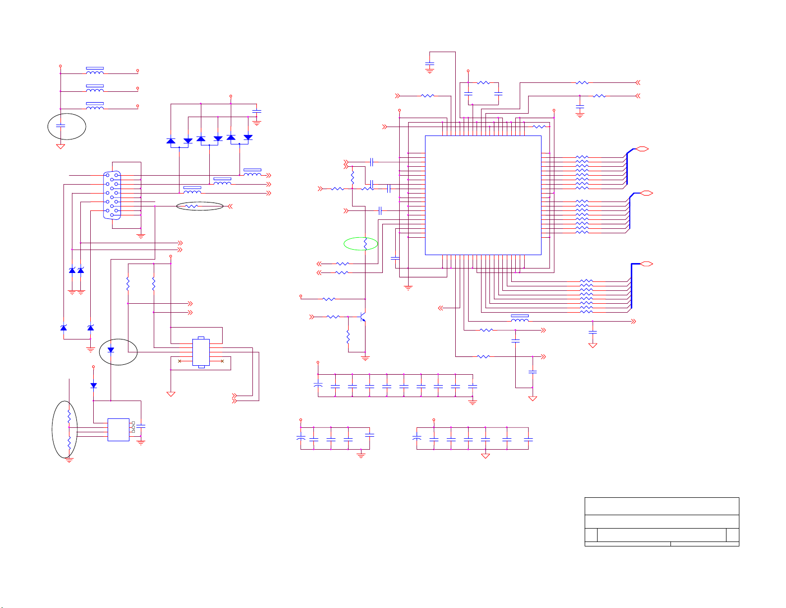
MLL752A
ZD500
3.3VA
VGA_SDA
NC
1K 1/16W
C536
0.1uF
AGND
ZD502
MLL752A
VGA_VS
AGND
RX
VGA_HS
AGND
D503
MLL4148
R512
R513
600 OHM
L502
600 OHM
600 OHM
VGA_VS
AGND
5V
VGA_SCL
VGA_SDA
L501
L503
11
12
13
14
15
VGA_SCL
ZD501
MLL752A
ZD503
MLL752A
CN501
8
7
6
1716
D504
MLL4148
U500
VCC
VCLK
SCL
24LC02
C501
AGND
C525
AD9883A
C518
0.1uF
0.1uF
AGND
R503
22 1/16W
U501
41
GND
42
VD
43
BAIN
44
GND
45
VD
46
VD
47
GND
48
GAIN
49
SOGIN
50
GND
51
VD
52
VD
53
GND
54
RAIN
55
A0
56
SCL
57
SDA
58
REF BY PASS
59
VD
60
GND
AD_SOG6
C519
0.1uF
+
3.3VDD
3.3V_AP
40
VD
PVD
GND
GND
CLAMP
MIDSCV
GNDVDGND
VSOUT
SOGOUT
HSOUT
61626364656667686970717273747576777879
C521
C520
0.1uF
0.1uF
C530
C531
0.1uF
0.1uF
R501
2.7K 1/16W
C500
0.0082uF
PVD
FILT
GND
VSYNC
HSYNC
DATACLK
GND
VDDR7R6R5R4R3R2R1R0
R510
75 1/16W
R511
75 1/16W
C522
0.1uF
AGND
C532
C533
0.1uF
0.1uF
COAST
0.082uF
GND
L500
C503
VD
3.3VDD
R505
1K 1/16W
21222324252627282930313233343536373839
VD
VDD
VDD
GND
GND
GND
C534
0.1uF
VDD
VDD
80
150 OHM
C511
100pF
GND
GND
VDD
GND
GND
B0
B1
B2
B3
B4
B5
B6
B7
G0
G1
G2
G3
G4
G5
G6
G7
C512
100pF
C535
0.1uF
20
19
18
17
16
15
14
13
12
11
10
9
8
7
6
5
4
3
2
1
AD_HS 6
AD_VS 6
3.3V_AP
3.3V_AD
3.3VDD
1
2
D500
BAV99
1
6
2
7
3
8
4
9
5
10
DB15
5VD_ADD C
NC
NC
NC
VSSSDA
RED
GREEN
BLUE
TX GOUT0
AGND
5VP
R509
R508
4.7K 1/16W
0.1uF
C523
4.7K 1/16W
1
2
3
45
AGND
3
L504
600 OHM
R500
1K 1/16W
VGA_VS 2
VGA_HS 2
TX
RX
CN500
2
4
6
8
10
33L800910H
BAV99
TX 5
RX 5
CONN
D501
5VP
C502
0.1uF
1
2
1
2
3
L505
600 OHM
1
3
5
7
9
NC
SCL3,4, 5,6,8,11
SDA3,4,5, 6,8,11
D502
BAV99
3
600 OHM
ISP 5
L506
AGND
VGA_R 2
VGA_G 2
SCART_CVBS1, 2
VGA_B 2
VIDEO_SEL2, 6
3.3V_AP
C524
10uF/16V
SCL3,4 ,5,6,8,11
SDA3,4,5, 6,8,11
5V
R648 1K 1/ 16W
3.3V_AD
C513
100uF/16V
+
VSEL_B2
VSEL_G2
R653
NC
R651 0 1/16W
VSEL_R2
R506
75 1/16W
R507
75 1/16W
R649 2.2K 1/16W
C514
+
0.1uF
C527
C526
0.1uF
0.1uF
R515
NC
1
R514
1K 1/16W
AGND
C515
0.1uF
C528
0.1uF
AGND
COAST6
C505
0.47uF/ 50V
C506
0.47uF/ 50V
R650
0 1/16W
0.47uF/ 50V
32
Q500
PMBS3904
AD_Clamp6
3.3V_AD
C507
0.001uF
C508
C509
0.1uF
C516
C517
0.1uF
0.1uF
C529
0.1uF
100uF/16V
R502
22 1/16W
R504
C504
22 1/16W
33pF
AGND
RP501
100 1/16W
1
8
BOUT0
100 1/16W
RP503
RP504
100 1/16W
1
2
3
4
1
2
3
4
RP505
100 1/16W
BOUT1
7
6
BOUT2
BOUT3
5
BOUT4
8
7
BOUT5
BOUT6
6
BOUT7
5
8
7
6
5
8
7
6
5
8
7
6
5
8
7
6
5
C510
22pF
2
3
4
1
2
3
4
RP500 100 1/16W
RP502
1
2
3
4
1
2
3
4
100 1/16W
GOUT1
GOUT2
GOUT3
GOUT4
GOUT5
GOUT6
GOUT7
ROUT0
ROUT1
ROUT2
ROUT3
ROUT4
ROUT5
ROUT6
ROUT7
VSEL_VS 2
VSEL_HS 2
BOUT[0..7] 6
GOUT[0..7] 6
ROUT[0..7] 6
AD_CLK 6
NC
AOC (Top Victory) Electronics Co., Ltd.
Titl e
Size Document Number Rev
Date: Sheet of
32
AD9883
Wednesday , April 07, 2004
TV2054-2Ea
9
1.0
13
Page 33
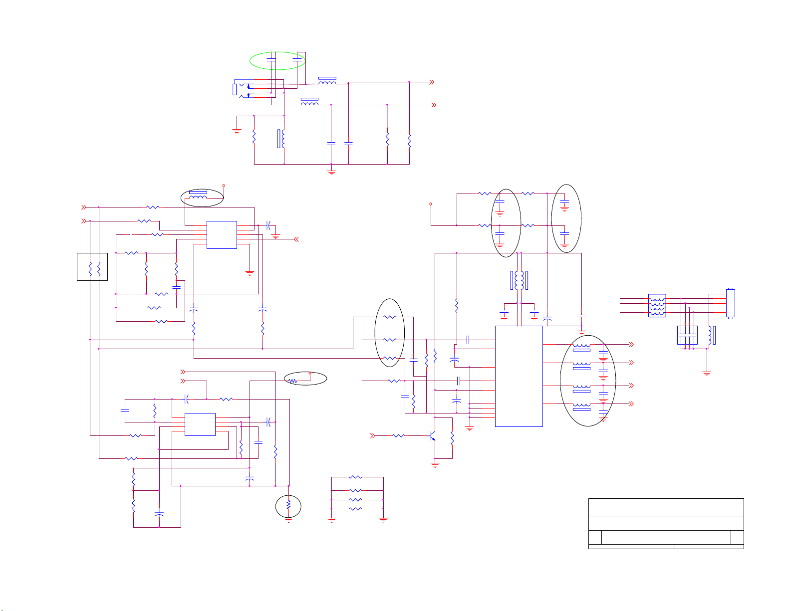
C672
CN601
PC_AUD IO
C673
330p
1
5
4
3
2
330p
L600
L604
300 OHM
300 OHM
del c632.c633
PC_L 11
PC_R 11
L_OUT11
R_OUT11
For without SRS
R4
L605
0 1/10W
C638
22uF/16V
+
C643
+
2.2uF/ 16V
R624
100 1/16W
C648
+
C6580. 001uF
150 OHM
R652 0 1/16W
R633
10K 1/16W
AGND
U600
1
VCC
2
IN R
3
DIFF
4
FILTER
5 6
OUT R GND
M62438FP
C642
+
2.2uF/ 16V
R623
100 1/16W
10K 1/16W
U603
PT2308S
8V
REF IN
IN L
OUT L
CNTL
R626
3.9K 1/16W
10
9
8
7
100uF/16V
R632
+
C652
100uF/16V
L610
R613
100 1/16W
R614
100 1/16W
C639
R616
R618
3.9K 1/16W
R631
3.9K 1/16W
R635
3.9K 1/16W
R637
R638
1K 1/16W
R615
1K 1/16W
31.6K 1/16W
0.47uF/ 50V
3.9K 1/16W
R621
4.7K 1/16W
1.5K 1/16W
R627
R620
R622
10uF/16V
0.47uF/ 50V
100K 1/16W
R617NC
R600NC
47K 1/16W
C641
0.0047uF
C6590. 001uF
1K 1/16W
R619
C640
EAR_L1
EAR_R1
+
C653
150 OHM
C646
100uF/16V
+
1 8
OUT1 VDD
2 7
IN1- OUT2
3 6
IN1+ IN2-
4 5
GND IN2+
SRS_CTL 6
5V_A
R658
0 1/10W
C634
560pF
R656
R657
R645 0 1/10W
AGND
C635
560pF
MUTE6
0 1/10W
R459
R611
10K 1/16W
PRE_L
PRE_R
0 1/10W
0 1/10W
R646
NC
R628
1K 1/16W
R647
NC
R634
1K 1/16W
10K 1/16W
AUDIO_GND
R639
C6570. 001uF
C6560. 001uF
R636
PMBS3904
R612
10K 1/16W
R630
1K 1/16W
1K 1/16W
1
Q600
12V_A
R629
10K 1/16W
C650
0.22uF
C651
10uF/16V
32
R625
10K 1/16W
C649
+
10uF/16V
+
R640
10K 1/16W
C647
0.22uF
R654
3.9 3W
R643
3.9 3W
C655
0.1uF
150 OHM
7
9
13
14
8
1
10
11
20
C668
0.1uF
0.1uF
L607
IN1
ST_BY
S_GND
IN2
MUTE
PW_GND
PW_GND
PW_GND
PW_GND
C669
6
VCC
U602
TDA7266D
R655
3.9 3W
R644
3.9 3W
L608
150 OHM
15
VCC
OUT1+
OUT1-
OUT2+
OUT2-
C654
0.1uF
+
C644
220uF/16V
2
5
19
16
C670
0.1uF
C671
0.1uF
LP600
L611
L612
L613
L614
C645
0.1uF
120 OHM
120 OHM
120 OHM
120 OHM
C664
0.1uF
C665
0.1uF
C666
0.1uF
0.1uF
C667
EAR_R
PRE_R
PRE_L
EAR_L
Audio_L+ 1
Audio_L- 1
Audio_R+ 1
Audio_R- 1
6
7
8
120 OHM(8P4R)
CP600
22pF
45
3
2
1
678
123
AOC (Top Victory) Electronics Co., Ltd.
Tit le
Size Doc ument Number Rev
A3
Date: Sheet
AUDIO
TV2054-2Ea
CN600
5
4
3
2
1
CONN
L606
150 OHM
4 5
1.0
of
10 13Wednesday , April 07, 2004
33
Page 34
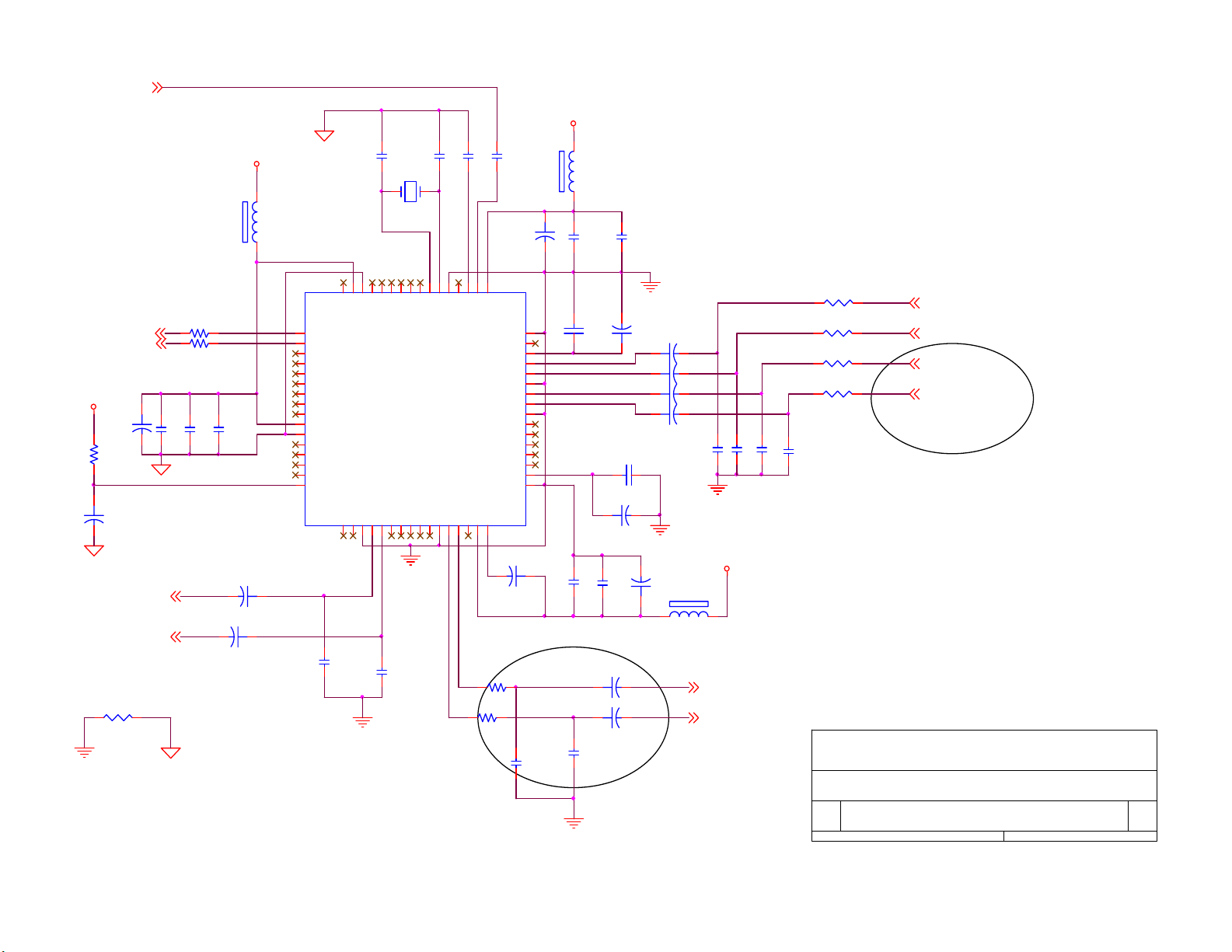
TUNER_SIF3
5V_A
5V_A
SCL3,4, 5,6, 8,9
SDA3,4, 5,6, 8,9
C614
10uF/16V
R607
4.7K 1/16W
+
C623
22uF/ 16V
R_OUT10
L_OUT10
R608
0 1/16W
+
100 1/ 16W
100 1/ 16W
C615
0.0015uF
R602
R604
C616
220pF
C617
470pF
C627
1uF/16V
+
C629
1uF/ 16V
5V_A
+
L602
600 OHM
1
SCL
2
SDA
3
I2S_CL
4
I2S_WS
5
I2S_DA_OUT
6
I2S_DA_IN1
7
ADR_DA
8
ADR_WS
9
ADR_CL
10
DVSUP
11
DVSS
12
I2S_DA_IN2
13
NC
14
NC
15
NC
16
RESETQ
C630
0.01uF
NC
STAN DBYQ
ADR_SEL
C601
3.3pF
18.432MHz
6061626364
NC
D_CTR_I/OUT1
D_CTR_I/OUT0
X60 0
NC
NC
U601
TP
XTAL_OUT
C602
3.3pF
XTAL_IN
C603
56pF
ANA_IN-NCTEST EN
MSP3455
NCNCVREF 2
DACM_R
DACM_LNCNCNCNCNCVREF 1
171819202122232425262728293031
C631
0.01uF
SC1_OU T_R
SC1_OU T_LNCAHVSU P
100 1/ 16W
100 1/ 16W
C604
56pF
100uF/ 16V
4950515253545556575859
AVSUP
AVSS
ANA_IN 1+
MON _I N
VREF TOP
SC1_I N_R
SC1_I N_L
ASG
SC2_I N_R
SC2_I N_L
ASG
AGNDC
AHVSS
CAPL_M
32
C625
10uF/16V
R805
R806
C660
0.01uF
NC
NC
NC
NC
NC
C605
+
48
47
46
45
44
43
42
41
40
39
38
37
36
35
34
33
0.01uF
+
C600
0.0015uF
C661
L601
600 OHM
C606
470pF
C608
0.1uF
C607
0.0015uF
C609
+
10uF/16V
C622
0.1uF
+
C624
3.3uF /16V
C628
470pF
1uF/ 16V
C662
+
C663
+
1uF/ 16V
C626
+
10uF/ 16V
C610
+
1uF/16V
+
C611
1uF/16V
+
C612
1uF/16V
+
C613
1uF/16V
C618
330pF
L603
600 OHM
C619
330pF
8V
LIN E_O_L 1
LIN E_O_R 1
C620
330pF
R601
470 1/ 16W
470 1/ 16W
C621
330pF
R603
470 1/16W
R605
R606
470 1/16W
ASEL_O_R 2
ASEL_O_L 2
PC_R 10
PC_L 10
AOC (Top Victory) Electronics Co., Ltd.
Tit le
Size Document Number Rev
A4
Wednes day , April 07, 20 04
Date: Sheet of
Audio decoder
TV2054-2Ea
11
1.0
13
34
Page 35
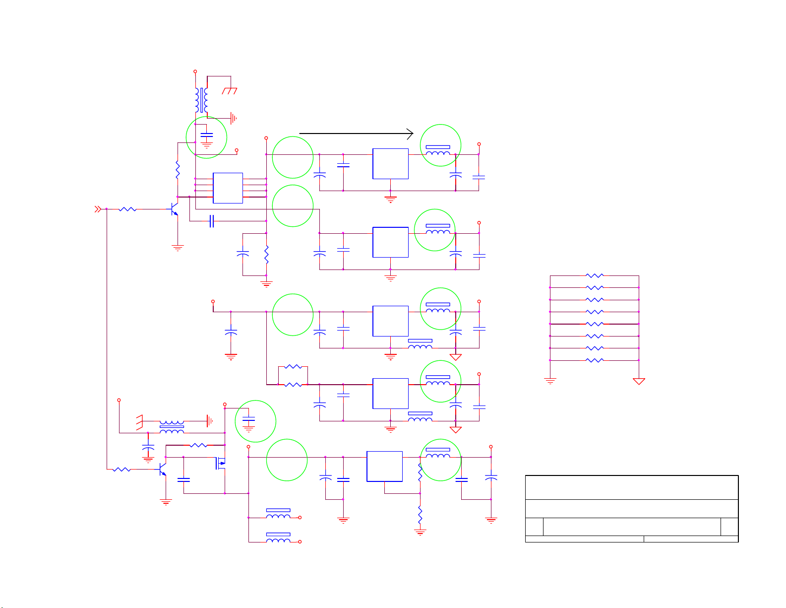
+5VP
45
L701
L
13
AGND
C725
0.1uF
AGND
R701
47K 1/16W
R702
PWR_ON5
22K 1/16W
12VP
C719
10uF/16V
R705
22K 1/16W
PMBS3904
AGND
1
Q703
PMBS3904
+
Q702
45
1
L707
L
32
AGND
32
AGND
13
1
2
3
4
C705
0.1uF
5VP
AGND
R704
47K 1/16W
C722
0.1uF
Q701
S1
S1
S1
G1
AO4403
C706
47uF/16V
AGND
12VS
AO3401
Q700
5VP
8
D1
7
D1
6
D1
5
D1
+
+
C710
100uF/16V
12V
5V
AGND
C726
0.1uF
AGND
5V
R703
3K 1/16W
6.2 1W
6.2 1W
L709
600 OHM
L700
600 OHM
R719
R718
10uF/16V
10uF/16V
10uF/16V
10uF/16V
C701
C707
C711
C715
C720
10uF/16V
12V_A
12V_T
move
U701
3 2
VI VO
C702
0.1uF
+
+
+
+
C700
0.1uF
C712
0.1uF
C716
0.1uF
3 2
+
C723
0.1uF
AGND
GND
1
AGND
U702
3 2
VI VO
GND
1
AGND
U700
3 2
VI VO
GND
1
AGND
U703
3 2
VI VO
GND
1
AGND
U704
VI VO
GND
1
L705
600 OHM
L710
600 OHM
120 1/16W
AGND
L702
600 OHM
C703
10uF/16V
L703
600 OHM
C708
10uF/16V
L704
600 OHM
C713
47uF/16V
L706
600 OHM
C717
47uF/16V
L708
600 OHM
R700
R706
620 1/8W
3.3VS
+
+
+
+
3.3VA
C724
0.1uF
3.3VM
2.5V
C704
0.1uF
C709
0.1uF
C714
0.1uF
C718
0.1uF
8V
AGND
+
10uF/16V
5VP : From Power Supply 5V
12VP : From Power Supply12V
8V :FOR MSP3455G/M62438/uPD64038
5V : For Tuner/VPC3230D/MSP3455G/
TVP5150/PT2308/PT2314/Z86129/uPD64038
3.3VS : For Video Decoder VPC3230D
/ Teltext SAA5264
3.3VA : For ADC AD9883
3.3VM : For Scaler spv301
2.5V : For Scaler spv301
12V_A : For Audio AMP TDA7266D
12V_T : For tuner boost
R717 0 1/10W
R716 0 1/10W
R715 0 1/10W
R714 0 1/10W
R713 0 1/10W
R712 0 1/10W
R711 0 1/10W
R710 0 1/10W
AGND
C721
AOC (Top Victory) Electronics Co., Ltd.
Tit le
Size D ocum ent Num ber Rev
A4
Wednesday , April 07, 2004
Date: Sheet of
POWER
TV2054-2Ea
1.0
12
13
35
Page 36
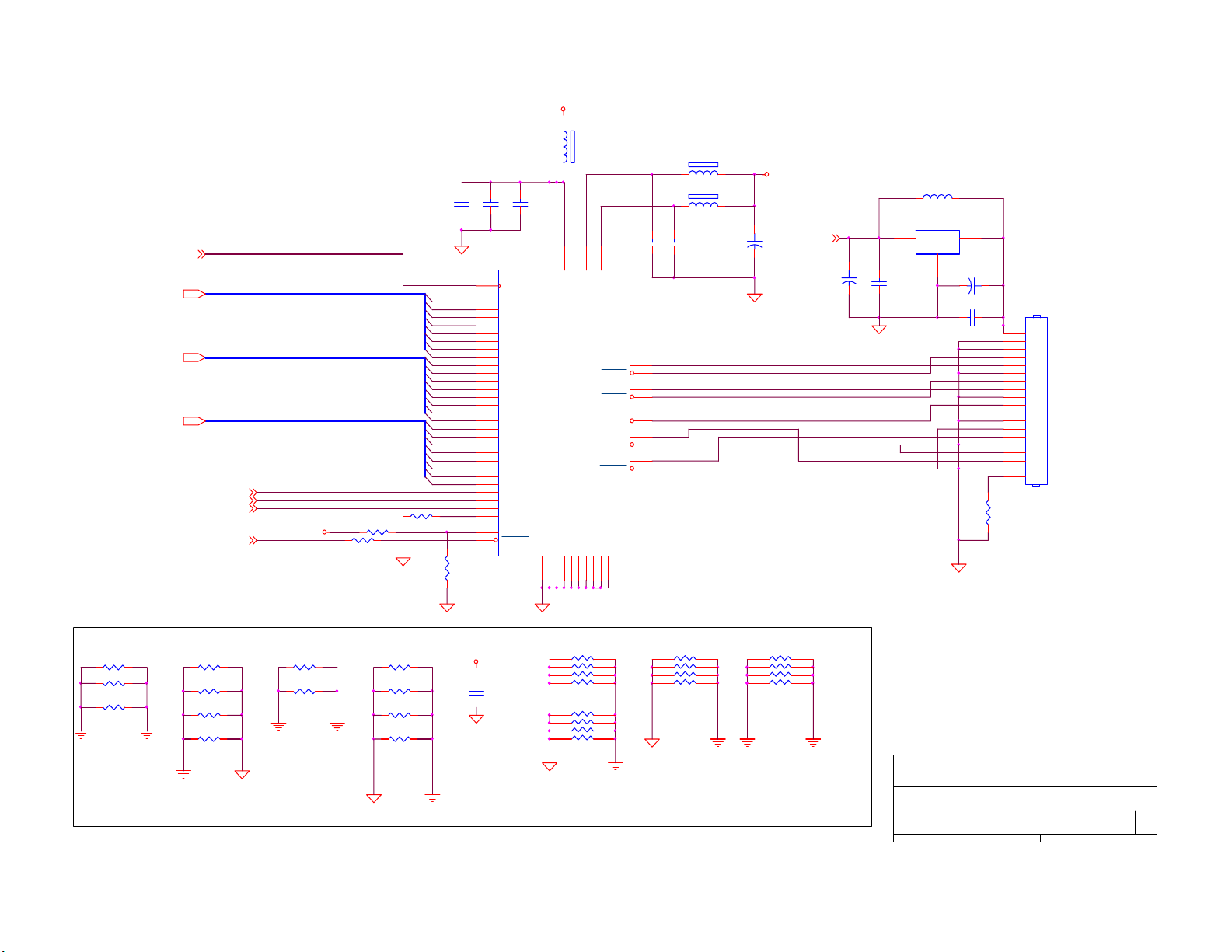
3.3VM
L802
600 OHM
R804
C802
0.1uF
C803
0.1uF
C800
OVCC
OGND2
49
PVCC
TXOUT0
TXOUT0
TXOUT1
TXOUT1
TXOUT2
TXOUT2
TXOUT3
TXOUT3
TXCOUT
TXCOUT
PGND1
OGND3
PGND2
0.1uF
47
48
45
46
41
42
37
38
39
40
19263444
31
CLKIN
51
TXIN 0
52
TXIN 1
54
TXIN 2
55
TXIN 3
56
TXIN 4
3
TXIN 6
50
TXIN 27
2
TXIN 5
4
TXIN 7
6
TXIN 8
7
TXIN 9
11
TXIN 12
12
TXIN 13
14
TXIN 14
8
TXIN 10
10
TXIN 11
15
TXIN 15
19
TXIN 18
20
TXIN 19
22
TXIN 20
23
TXIN 21
24
TXIN 22
16
TXIN 16
18
TXIN 17
27
TXIN 24
28
TXIN 25
30
TXIN 26
25
TXIN 23
17
VCC
32
PWRDN
VCC1
VCC2
VCC3
U800
NT7181FQ
GND1
GND2
GND3
GND4
GND5
51321295333353643
OGND1
C801
0.1uF
P_CLK1,6
R[0..7]1,6
G[0.. 7]1,6
B[0..7]1, 6
P_Hs1,6
P_Vs1,6
P_DATAEN1,6
LVDS_EN5
3.3VM
R803
NC
R800
0 1/16W
R0
R1
R2
R3
R4
R5
R6
R7
G0
G1
G2
G3
G4
G5
G6
G7
B0
B1
B2
B3
B4
B5
B6
B7
R802
10K 1/16W
600 OHM
600 OHM
C805
0.1uF
TXA0m
TXA0p
TXA1m
TXA1p
TXA2m
TXA2p
TXA3p
TXACKp
L800
L801
+
C804
10uF/16V
3.3VM
PAN_PWR1,5
C806
10uF/16V
L803NC
U802
1 3
IN OUT
GND
LM3940S-3.3
0.1uF
2
C809
+
10uF/16V
R801
1K 1/16W
CN800
1
2
3
4
5
6
7
8
9
10
11
12
13
14
15
16
17
18
19
20
CONN
C808
0.1uF
+
C807
R1 0 1/8W
R2 0 1/8W
R16
0 1/10W
AGND
AGND
R3 0 1/10W
R9
0 1/10W
R10 0 1/ 16W
R11 0 1/ 8W
R5 0 1/10W
R7 0 1/10W
AGND
RN1
0
1
R12 0 1/ 10W
R13 0 1/ 10W
R14 0 1/ 10W
R15 0 1/ 10W
AGND
3.3VA
C1
0.1uF
8
2
7
3
6
4
5
RN2
0
1
8
2
7
3
6
4
5
AGND
RN3
0
1
8
2
7
3
6
4
5
RN4
8
7
6
5
AGND
For EMI
0
1
2
3
4
AOC (Top Victory) Electronics Co., Ltd.
Tit le
Size Document Number Rev
B
Date: Shee t of
LVDS
Wednesday , April 07, 2004
TV2054-2Ea
1.0
13
13
36
Page 37
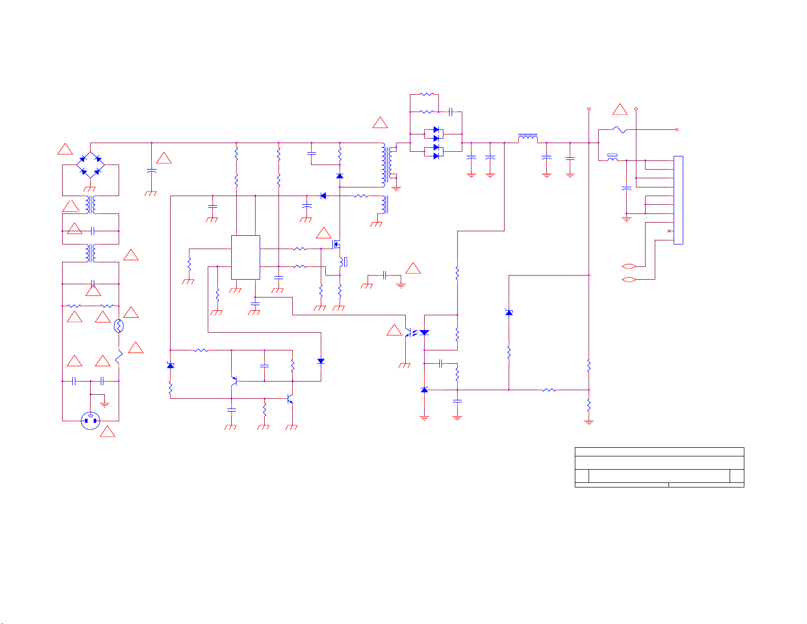
8.2 Power Board
1
!
BD901
GBU405
2
!
C904 0.22uF/275V
!
!
R901
1M(1206)
!
C901
220PF/250V
3
-+
4
2 3
L902
73L174-31
1 4
2 3
1 4
0.47uF/250V
!
C903
!
1M(1206)
R902
!
C902
220PF/250V
3
12
CN901
!
!
L901
73L174-29-LS
!
NR901
61L58-050-WT
!
F901
2.5A/250V
+
!
C905
150uF/400V
ZD901
RLZ20B
R917
100
R911
24KF
R915
4.7K
R906
1M(1206)
R907
1M(1206)
C908
0.1UF
IC901
SG6841
4
SG6841
56
13
R912
20K
Q902
2N3906
C912
0.1UF
R919
47_1/2W_M
R920
47_1/2W_M
!
T901
PQ26/22.5
4
O
12
6
3
O
2
C921
4700PF/250V
11
8
O
7
80LL17T-5
!
43
R909
10(1206)
R910
0
D902
PS102R
+
C907
22UF/50V
R913
20K
C906
152P/1KV
!
1
32
R903
100K_2W
D901
FR107
R908
3R3/1206
Q901
2SK2996
FB901
BEAD
R914
0.3_2W
R904
1M(1206)
R905
1M(1206)
72
8
C909
NC
C910
NC
!
D903
C911
0.1uF/50V
R918
4.7K
R916
4.7K
Q903
2N3904
1N4148/SMD
IC903
HTL431
D910
MOSPEC20100
D911
MOSPEC20100
12
IC902
PC123FY2 4P
C918
0.1UF
C913
102P_500V
+
C914
2200UF/16V
R921
240(1206)
R922
1K
R923
0
C919
NC
+
C915
2200UF/16V
L903
73L-253-91L
1
ZD902
RLZ12B
R924
1K
2
470UF/16V
R925
1K
!
F902
5A/24V/1206
5Vout
12Vout
12V
TO INVERTER
+
C916
C917
0.1UF
FB902
BEAD
C920
1000UF/16V
1
12V
12V
5V
5V
GND
GND
GND
TO AUDIO
2
3
+
4
5
6
7
8
9
10
CN902
ON/OFF
ADJ
R926
9.31KF
R927
2.43KF
Title
<Title>
Size Document Number Rev
<Doc> <RevCode>
B
Date: Sheet
of
11Tuesday, November 16, 2004
37
Page 38
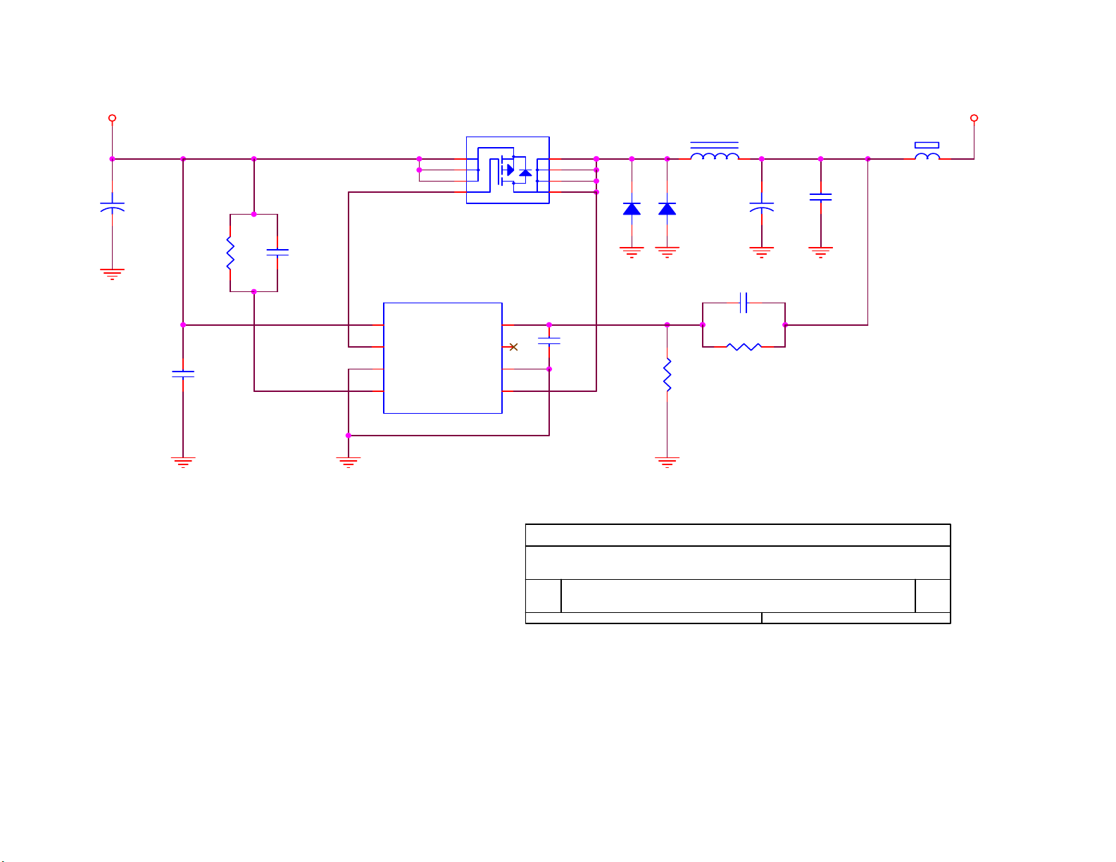
12V
C101
+
1000uF/16V
R101
39K
C102
0.1UF
C103
10NF
8
7
6
5
VIN
PGATE
PWR GND
ADJ
1
2
3
4
LM3485
IC102
Isense
MINI SO8
Q101
SI4431DY-T1
4
FB
3
N.C
2
GND
1
8
7
6
5
C104
NC
D101
SR24
D102
SR24
R103
20KF
L101
22UH
+
C106
1000uF/16V
C105
100PF(NPO)
R102
60KF
C107
0.1UF
5Vout
FB101
BEAD
Title
Size Document Number Rev
Date: Sheet
<Title>
<Doc> <RevCode>
B
of
11Tuesday, November 16, 2004
38
Page 39
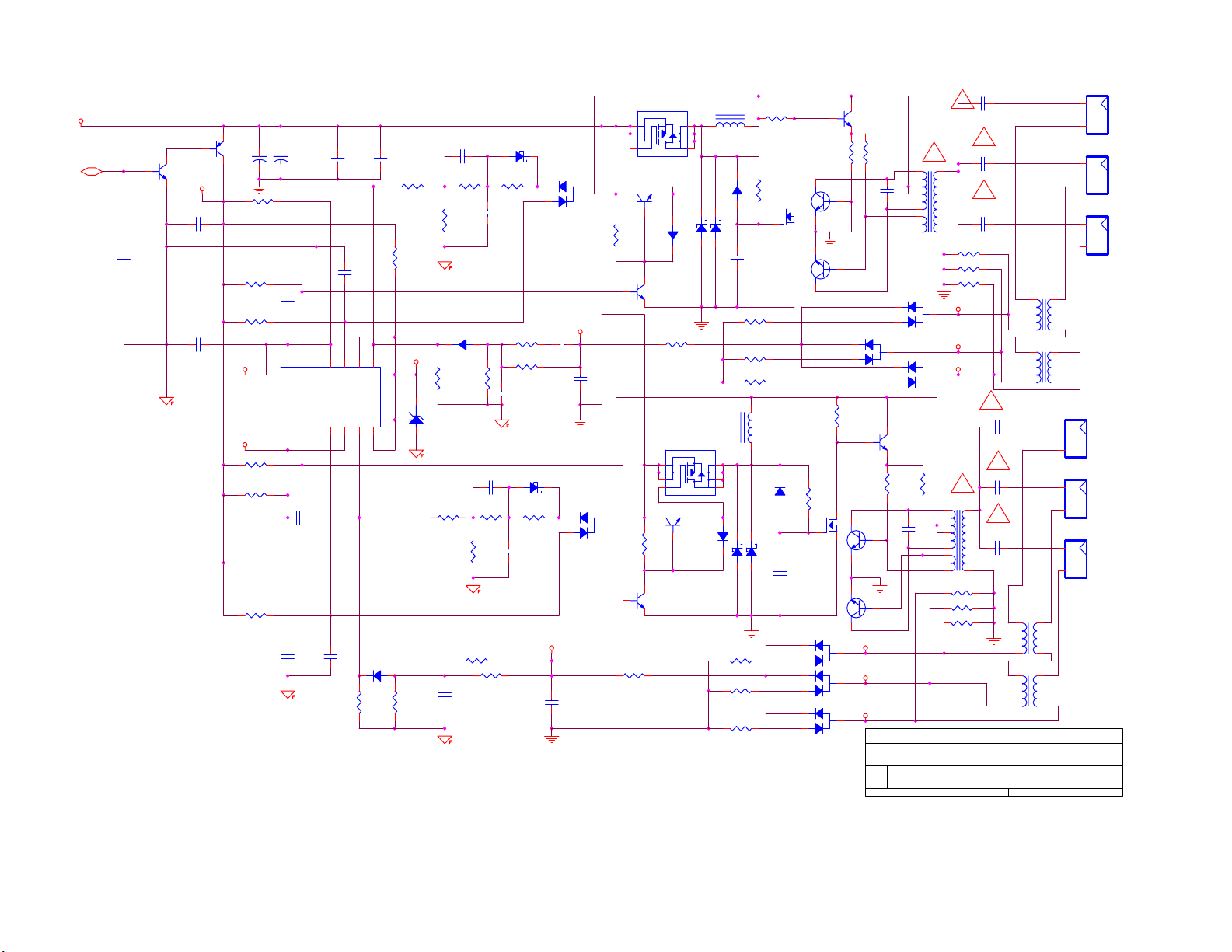
12Vout
ON/OFF
Q204
DTC144WKA
C210
0.1UF
DTA144WKA
+12VCC
C208
1UF
0.1UF
C214
Q203
1
23
1000UF/25V
C203
R211 15K
R217
R219 18K
BU_R
BU_L
R229 4.7K
R234 15K
4.7K
R244
18K
0.1UF
C213
0.1UF
IC201
C226
1000UF/25V
C204
13
14
OUT_3
OUT_2
1234567 8
C221
0.1UF
OUT_4
LM339M
OUT_1
C245
0.1UF
C212
1000PF
9
10
11
12
GND
IN_4 -
IN_3 +
IN_4 +
VCC
IN_1 -
IN_1 +
IN_2 -
C227
1000PF
R251
8.2K
D218
IN_2 + IN_3 -
R252
NC
C246
0.1UF
1N4148
R207
6.8K
R214
4.7K(1206)
V_REF
3
2 1
8.2K
IC202
TL431
C202 0.01UF
R208
R212
7.5K
D208 1N4148
R225
R237
6.8K
R241
7.5K
C229
0.1UF
16K
R226
NC
C220 0.01UF
R238
16K
R246
2.7K
R248
18K
D201
RLZ8.2B
R209 0
C207
0.1UF
R224
C217
0.1UF
C228
R221
2.7K
18K
D211
RLZ8.2B
R239
0
C224
0.1UF
0.022UF
C230
0.22UF
D202
BAV99
C215
0.022UF
C216
0.22UF
D213
BAV99
V_SENSOR_8
V_SENSOR_7
SST3904
Q201 SI4431 OR AO4411
1
2
3
4
Q206
SST3904
D206
R213 3.9K
1N4148
Q209
SST3904
1
2
3
4
R240
3.9K
Q215
4.3K
R249
8
7
L201
6
150UH(60-52)
5
D204
SMAL240 OR SR24
R222 4.3K
Q211 SI4431 OR AO4411
Q212
SST3904
D214
1N4148
D205
NC
8
7
6
5
R247 30K
R250 30K
R253 30K
D2031N4148
C211
1UF
R220 30K
R223 30K
R227 30K
L204
D212
D215
D216
NC
SMAL240 OR SR24
R201 4.7K
R210
1M
1
Q207
RK7002
150UH(60-52)
32
1N4148
C225
1UF
D217
D219
D220
RK7002
R202
1K MOF-DIP(1W)
23
Q205
1
KTD1691(DIP&SMD)
Q208
1
KTD1691(DIP&SMD)
2 3
R228
4.7K
R236
1M
32
23
1
Q213
2 3
BAV99
BAV99
BAV99
C201
27P/3KV
Q202
SST3904
R204
1K MOF-DIP(1W)
C206
0.22UF/250V
80VL20T-1-dn
D209
BAV99
Q210
SST3904
R230
1K MOF-DIP(1W)
C223
Q214
0.22UF/250V
1
KTD1691(DIP&SMD)
Q216
1
KTD1691(DIP&SMD)
V_SENSOR_4
V_SENSOR_5
V_SENSOR_6
Title
<Title>
Size Document Number Rev
<Doc> <RevCode>
B
Date: Sheet
!
!
9
71
R215 1K(1206)
R216 1K(1206)
R218 1K(1206)
V_SENSOR_1
V_SENSOR_2
V_SENSOR_3
PT202
5
3
4
2
6
80VL20T-1-dn
R242 1K(1206)
R243 1K(1206)
R245 1K(1206)
C205
27P/3KV
!
C209
27P/3KV
73L174-39-ys
L202
1 3
.
.
2 4
L203
1 3
.
73L174-39-ys
.
2 4
!
C218
27P/3KV
!
C219
!
27P/3KV
9
!
C222
27P/3KV
71
1 3
2 4
73L174-39-ys
1 3
2 4
73L174-39-ys
CN202
1
2
CN204
1
2
CN206
1
2
L205
.
.
L206
.
.
12Tuesday, November 16, 2004
of
!
PT201
5
3
4
2
6
D207
BAV99
D210
BAV99
R232
1K MOF-DIP(1W)
CN201
1
2
CN203
1
2
CN205
1
2
SM02B-BHSS-1-TB
SM02B-BHSS-1-TB
SM02B-BHSS-1-TB
SM02B-BHSS-1-TB
SM02B-BHSS-1-TB
SM02B-BHSS-1-TB
39
Page 40
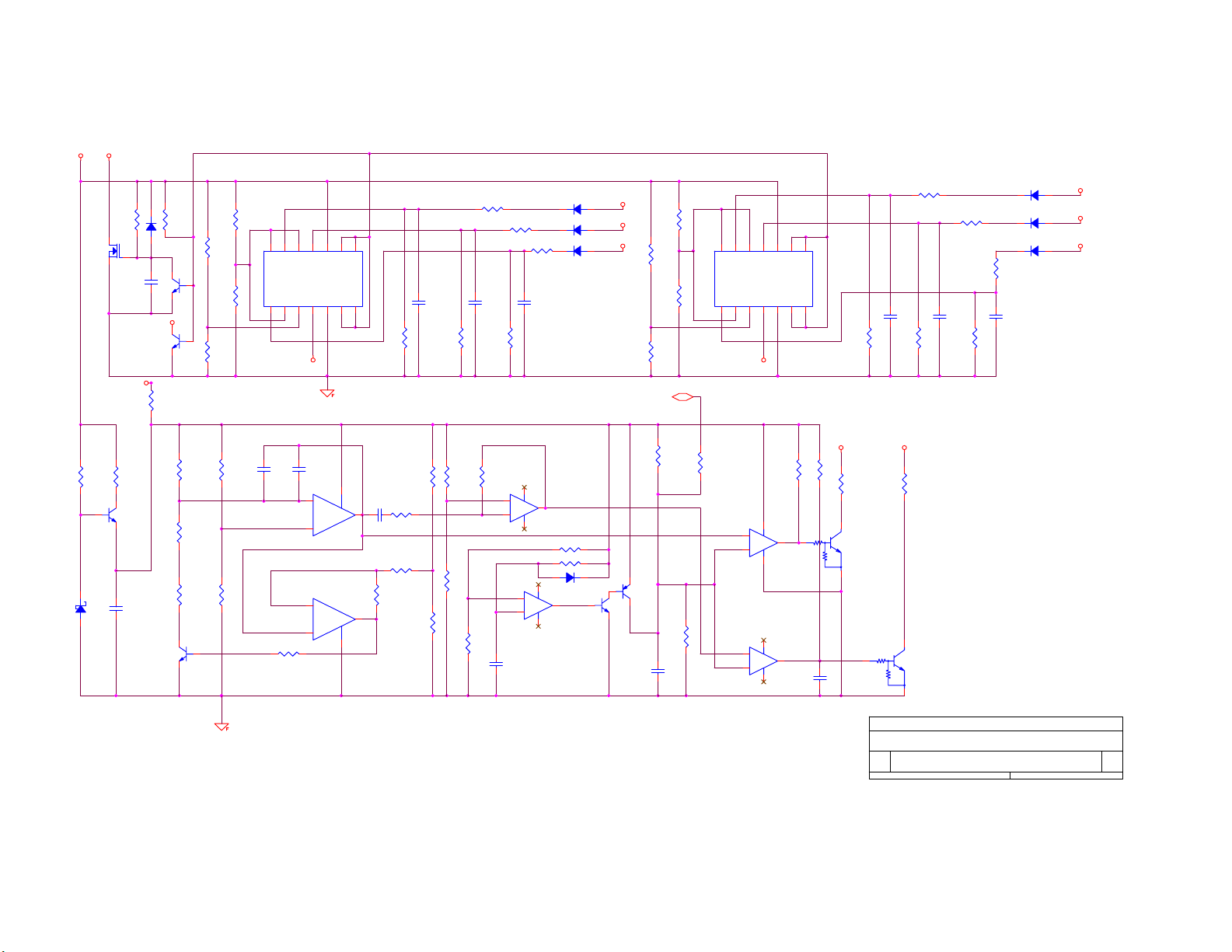
+12VCC
V_REF
R269
1K
D229
RLZ5.6B
R256
2M
Q217
32
RK7002
100 (1206)
Q219
1
C231
4.7UF
Delay-DIM
5Vout
R270
SST3904
C241
2.2UF
D223
1N4148
R266
NC(1206)
R254
15K
Q218
SST3904
Q225
SST3904
R267
100K
R279
30K
R284
27K
SST3904
Q222
R255
R291
680K
R259
100K
R292
C235
0.1UF
R264
1M
BU_L
3
2
Q223
R298
300K
R277
0
R299
300K
C236
0.1UF
R265
1M
V_SENSOR_1
D222 1N4148
V_SENSOR_2
D225 1N4148
V_SENSOR_3
D226 1N4148
R283 2M
D228 1N4148
1
LM324/SO_15
R261
R293 300K
R294 300K
R295 300K
R262
R273
1M
C234
0.1UF
1M
411
5
+
7
6
-
IC206B
LM324/SO_15
R280 100K
411
3
+
2
-
IC206A
C243
1UF
C233
0.1UF
1M
R272
300K
R282
200K
R289
100K
10K
123
4
5
6
78
VCC
IN_1 -
IN_2 -
IN_1 +
IN_2 +IN_3 -
LM339M
IC203
1M
R268
51K
R285
51K
IN_3 +
910111213
V_SENSOR_7
C238
0.01UF
R290 10K
IN_4 -
2
3
5
6
C239
NC
-
+
+
-
IN_4 +
OUT_1
GND
OUT_4
IC205
ST LM358
4 8
14
LM358
OUT_2
R286
100K
C232
0.1UF
R260
1M
R271
1M
R278
1M
R281
51K
R287
1M
OUT_3
C240
1
0.1UF
7
R296
680K
R297
100K
Q221
DTC144WKA
R257
R258
Q224
DTC144WKA
C242
0.1UF
10K
1M
R274
47k
R288
150K
1
2
3
4
5
6
78
VCC
IN_1 -
IN_2 -
IN_1 +
IN_2 +IN_3 -
LM339M
IC204
IN_3 +
IN_4 -
910111213
V_SENSOR_8
ADJ
R275
56K
12
+
13
-
LM324/SO_15
10
+
9
-
IN_4 +
411
IC206D
411
IC206C
OUT_1
GND
OUT_4
1
14
LM324/SO_15
8
C247
0.01UF
14
R205
10K
OUT_2
OUT_3
R263
1M
BU_R
R206
10K
R276
0
3
Q220
DTC144WK
2
1
DTC144WK
D221 1N4148
D224 1N4148
D227 1N4148
R2100
300K
C237
0.1UF
V_SENSOR_4
V_SENSOR_5
V_SENSOR_6
Title
<Title>
Size Document Number Rev
<Doc> <RevCode>
B
Date: Sheet
of
22Tuesday, November 16, 2004
40
Page 41
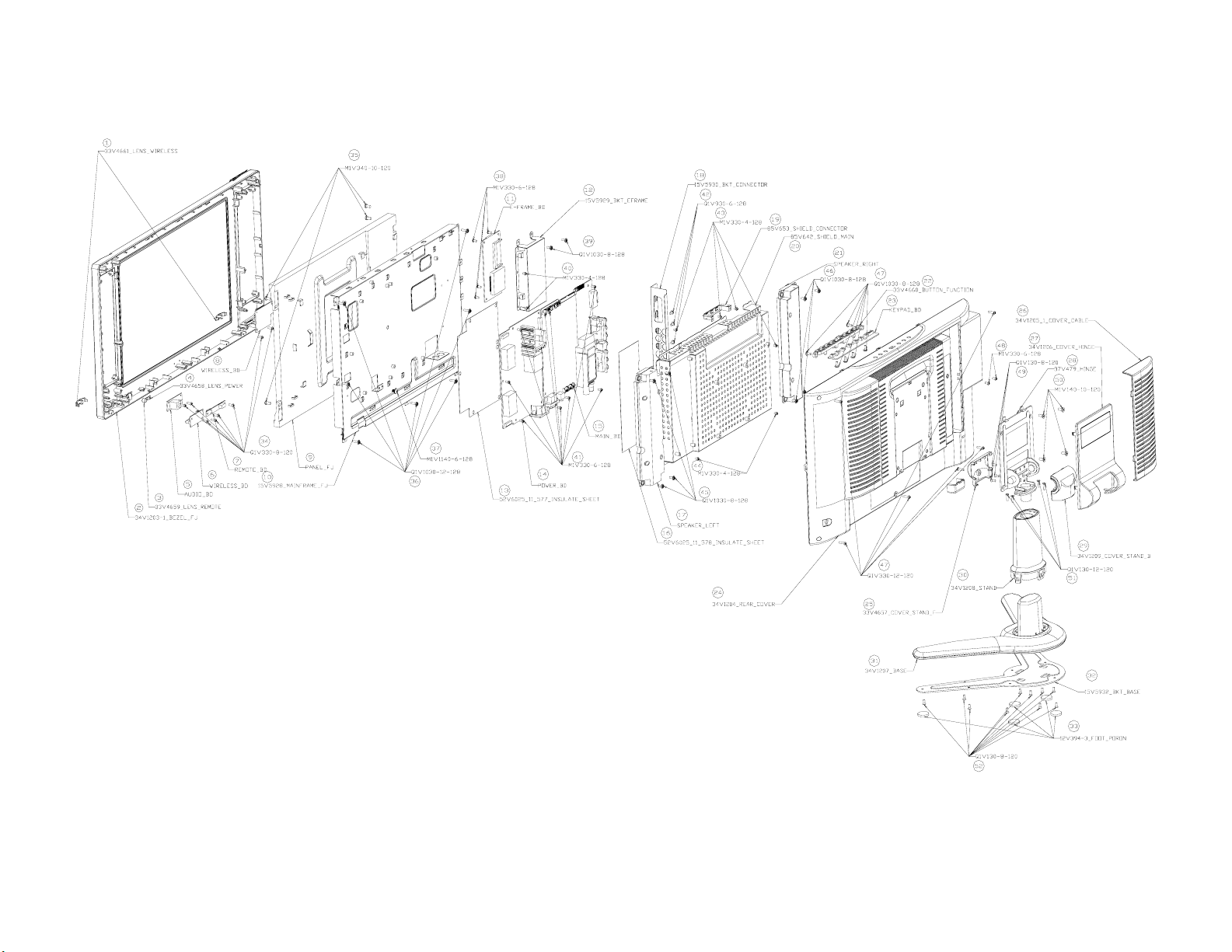
9. Explode View
41
Page 42

10. BOM List
Location Part NO. Description
007T 6 5S10 COMPOUND PALLET
015T5930 9 BKT CONNECTOR
015T8024 1 BKT-AC-LOCK
015T8152 1 MAIN FRAME
026T 800504 5 BARCODE
034T1522 GM L HANDLE
034T1529 GM L COVER HINGE
034T1530 GM L COVER HINGE
040T 58162457A I/O LABEL
044T2006 1 EPS
044T2006 2 EPS
044T2006 5 1A DEU 26 TV STAND BOX
044T600210A PAPER PLATE
044T9003 6 CORNER PAPER
044TZ001200 4B PIZZA BOX
045T 88606 3 PE BAG FOR BASE
045T 88609 20 EPE COVER-AOC
045T 88626 4 PE BAG FOR MONITOR
050T 500 1 CABLE TIE
052T 1185 MIDDLE TAPE FOR CARTON
052T 1186 SMALL TAPE
052T 1209500 ALUMINIUM TAPE
052T 1211 A ADHESIVE TYPE
052T 1211513 ALUMINIUM TAPE
052T6020 6 PROTECT FILM
052T6025 11676 INSULATE SHEET
085T 689 2 SHIELD MAN
089T176J 50518 FFC CABLE
092TB1JX1A31GF BATTERY
095T8014 2509 HARNESS 2P-2P 720MM
095T8014 3523 HARNESS 2P-3P 800MM
095T8014 5540 HARNESS 5P-5P 560MM
095T8014 8571 HARNESS
098TR7SW7NT F Remote Control
0M1T 330 4128 SCREW
0M1T 330 4128 SCREW
0M1T 330 6128 SCREW
0M1T 340 14120 SCREW M4X14
0M1T1130 6128 SCREW
0M1T1140 4128 SCREW 4X6
0M1T1140 6128 SCREW 4X6
0M1T1740 14120 SCREW
0M1T1740 14120 SCREW
0Q1T 130 8120 SCREW
0Q1T 140 20120 SCREW
0Q1T 330 8120 SCREW 3X8mm
0Q1T 340 12 47 SCREW T4X12
0Q1T 930 6128 SCREW T3X6
0Q1T1030 12128 SCREW
42
Page 43

750TVUA1S02 2 AU0 20.1 V4 PANEL
CBPFAB5BASA1T3 MAIN BOARD FOR SMT
PWTV2062AU1 20" POWER BOARD
Q40T 200953 1A RATING LABEL
Q44T2006953 1A CARTON
040T 58162435A LABEL
045T 76 28 RN PE BAG FOR MANUAL
Q41T3201953 1A MANUAL
Q41T7800953 1A QSG
011T 176 1 RL WIRE HOLDER
012T 394 3 RUBBER FOOT
015T6184 1 Kensington lock
015T8153 1 BKT-HINGE
015T8154 1 BKT-BASE1
033T4822ARG 1L ID2 KEYPAD COVER
033T4825 PO L ID FUN KEY
033T4826 PO L ID2 COVER POWERKEY
033T4827 1 C ID2 LENS
033T4828 ED C REMOTE LENS
033T4832 RG L CLIP CABLE
033T4837 RG L STAND TOP
033T6302 14 C PC PLATE ON TOP
034T1527 RG 2L AOC BEZEL
034T1528 GM L REAR COVER
034T1531 RG L STAND
036T 426 KN 4C SPEAKER GRILL
037T 525 2 HINGE
044T3231 15528 EVA WASHER
078T 443 1 L SPEAKER
078T 443 1 R SPEAKER
0M1T 330 4128 SCREW
0Q1T 130 8120 SCREW
0Q1T 140 16120 SCREW
0Q1T 330 8120 SCREW 3X8mm
0Q1T 330 8120 SCREW 3X8mm
0Q1T 330 8120 SCREW 3X8mm
0Q1T1040 10128 SCREW
HJPF5AA1P HEADPHONE JACK BOARD
IRPFA60AP IR BOARD
KEPFJ60KAP LCD TV KEY BOARD
T34T1532 RG L BASE-1
W33T4835AGM 2L COVER CARD READER
W33T4836 RG L STAND MID
CN112 033T3802 2H WAFER 2P RIGHT ANGLE
CN111 033T3802 3H WAFER 3P RIGHT ANGLE
CN600 033T3802 5H WAFER 5P RIGHT ANELE PI
CN107 033T3802 8H WAFER 8P RIGHT ANGLE PITCH 2.0
CN102 033T802210A H HEADER FEMALE 1*10P R/A 2.54MM
040T 457624 1B CPU LABEL
040T 45762412B CBPC LABEL
044T3231508512 CHIELD D-SUB
R718 061T 208629 64 6.2OHM +-5% 1W
705LAB5FB34002 BACK COVER ASS Y
43
Page 44

R719 061T 208629 64 6.2OHM +-5% 1W
R103 061T152M259 64 2.5 OHM 5% W2
R102 061T152M259 64 2.5 OHM 5% W2
R654 061T153M399 59 3.9 OHM+-5% 3W
R655 061T153M399 59 3.9 OHM+-5% 3W
R643 061T153M399 59 3.9 OHM+-5% 3W
R644 061T153M399 59 3.9 OHM+-5% 3W
C644 067T 305221 3T 220uf/16V
L707 073T 253137 ER CHOKE COIL BY EROCORE SCB-03
L701 073T 253137 ER CHOKE COIL BY EROCORE SCB-03
085T 583510 GASKET
J100 088T 78 13 2C RCA JACK
JP100 088T 100 6 TO 4PIN MINI DIN JACK
CN601 088T 30214K PHONE JACK
CN501 088T 35315F HA D-SU13 15PIN
J102 088T 35521A HC SCART CONN.R/A 21PIN
090T6068 2 HEAT SINK
X301 093T 22 61 J CRYSTAL 32.768 KHZ 3*9 NXF32
X400 093T 2251B 12MHZ/20PF/49US
X300 093T 2251B J NXS12.000AC30F-BT-2
X200 093T 2265B J 20.250 AE13F-BK4
X600 093T 22D60 BH CRYSTAL 18.432MHZ/12PF/49U
TU100 094TPASEALL 3P FQ1216ME/IH-5(SV22)
SMTFAB5BASA1T3 MAIN BOARD FOR SMT
CN902 033T800910N H 10P H:6.0/3.0MM
CN206 033T8021 2D U 3.5mm WAFER
CN205 033T8021 2D U 3.5mm WAFER
CN204 033T8021 2D U 3.5mm WAFER
CN203 033T8021 2D U 3.5mm WAFER
CN202 033T8021 2D U 3.5mm WAFER
CN201 033T8021 2D U 3.5mm WAFER
040T 45762420A S/N LABEL
051T 2 14
052T 1174 TYPE
IC902 056T 139 3A PC123Y22FZOF
Q205 057T 761 7 KTD1691P
Q208 057T 761 7 KTD1691P
Q214 057T 761 7 KTD1691P
Q216 057T 761 7 KTD1691P
NR901 061T 58050 WT NTC THERMISTOR
R232 061T 208102 64 1KOHM 5% 1W
R230 061T 208102 64 1KOHM 5% 1W
R204 061T 208102 64 1KOHM 5% 1W
R202 061T 208102 64 1KOHM 5% 1W
R903 061T152M10452G 100K OHM 5% 2W
R914 061T152M308 64 0.3 OHM 5% 2W
C903 063T 107474 HS 0.47UF K 275VAC
C904 063T107K224 US 0.22UF K 275VAC
C218 065T 3J2706ET 27PF +-5% 3KV TDK
C209 065T 3J2706ET 27PF +-5% 3KV TDK
C205 065T 3J2706ET 27PF +-5% 3KV TDK
C201 065T 3J2706ET 27PF +-5% 3KV TDK
C219 065T 3J2706ET 27PF +-5% 3KV TDK
热熔胶
44
Page 45

C222 065T 3J2706ET 27PF +-5% 3KV TDK
C901 065T305M1022BP 1000PF
C902 065T305M1022BP 1000PF
C924 065T305M2222B3 C-C220P/250V
C922 065T305M2222B3 C-C220P/250V
C921 065T306M4722BP 4700PF +-20% 400VAC
C915 067T215B102 4R 1000UF 25V 10*23
C914 067T215B102 4R 1000UF 25V 10*23
C905 067T215S15115K EC105C 150UF 450V
C920 067T215V102 3N GP KY16VB1000M-CC3 10*16
C916 067T215V102 3N GP KY16VB1000M-CC3 10*16
C204 067T215V102 3N GP KY16VB1000M-CC3 10*16
C203 067T215V102 3N GP KY16VB1000M-CC3 10*16
C101 067T215V102 3N GP KY16VB1000M-CC3 10*16
C108 067T215V102 3N GP KY16VB1000M-CC3 10*16
L205 073G 174 39YSA FILTER
L202 073G 174 39YSA FILTER
L203 073G 174 39YSA FILTER
L206 073G 174 39YSA FILTER
L902 073L 174 29LSH LINE FILTER
L901 073L 174 31LSG CHOKE COIL
L903 073T 253 91 LS CHOKE BY LI SHIN
L204 073T 253138 Y CHOKE BY
L201 073T 253138 Y CHOKE BY
L101 073T 253151 T CHOKE COIL
T901 080LL17T 5LSG ADAPTOR BY LISHIN
PT202 080LL17T 13DNG TRANSFORMER
PT201 080LL17T 13DNG TRANSFORMER
BD901 093T 50460 16 U4KB80R
705G 20 84 01 F901 ASS'Y
705L 20 57 01 Q901 ASS'Y
705L 20 93 01 D910 ASS'Y
705T 20 87 01 CN901 ASS'Y
PW2062AU1SMT PWOER BOARD FOR SMT ASS'Y
CN1 033T3802 5H WAFER 5P RIGHT ANELE PI
J1 088T 30230C PHONE JACK
SMTHJPF5AA1P TUNER BOARD SMT
CN2 033T3802 4 WAFER PH-4
U4 056T 627 3 TSOP4838
095T 900 53 HARNESS 95MM
SMTIRPFA60AP IR BOARD SMT
CN1 033T3802 4H WAFER 4P RIGHT ANGLE
S7 077T 600 1GCJ TACT SWITCH TSPB-2 -NP
S6 077T 600 1GCJ TACT SWITCH TSPB-2 -NP
S5 077T 600 1GCJ TACT SWITCH TSPB-2 -NP
S4 077T 600 1GCJ TACT SWITCH TSPB-2 -NP
S3 077T 600 1GCJ TACT SWITCH TSPB-2 -NP
S2 077T 600 1GCJ TACT SWITCH TSPB-2 -NP
S1 077T 600 1GCJ TACT SWITCH TSPB-2 -NP
D1 081T 12 3 GP GP3A032C/R003-ZR-50-HB
095T 900 59 WIRE HARNESS
SMTKEPFJ60KP LCD TV KEY BOARD AUTO INS
CN101 033T8019 50 CONNECTOR 50P
45
Page 46

U704 056T 133 30AAC AZ1117H-1.8-E1
U602 056T 535 3 TDA7266D
U300 056T 562 87 SPV302A PBGA-388 SUNPLUS
U501 056T 567 6 AD9883AKSTZ-140
U703 056T 585 5 RT9164-25PG
U101 056T 585 9 IC AP1117E50LA ANACHIP
U700 056T 585 4A AP1117E33LA
U701 056T 585 4A AP1117E33LA
U702 056T 585 4A AP1117E33LA
U601 056T 593 3 MSP3415G-QI-B8-V3PMQFP64(NICAM
U600 056T 593 6 M62438FP SOP-10
U100 056T 614 1 74HC4052D
U302 056T 615 8B IS42S16400B-7T TSOPII-54
U404 056T 615102 LP62S2048AX-70LLF
U603 056T 616 3 PT2308S SO-8 PTC
U403 056T 623 9 SAA5361HL/M1/1651 FQFP-100
U102 056T 625 1 NJM-2244M-TE1/JRC
U405 056T 634 2 PI5V330Q QSOP-16 BY PER
U200 056T 640 1 VPC3230D
U301 056T 652 1 PCA9554PW TSSOP-16 PHILIPS 8BI
U310 056T1133 52 A29L040L-70 PLCC-32
U500 056T113334A M24C02-WMN6TP
U400 056T113334A M24C02-WMN6TP
U304 056T113356A 24LC16BT/SN SOIC-8PI
Q703 057T 417 4 CHIP PMBS3904 BY PHILIPS
Q702 057T 417 4 CHIP PMBS3904 BY PHILIPS
Q600 057T 417 4 CHIP PMBS3904 BY PHILIPS
Q500 057T 417 4 CHIP PMBS3904 BY PHILIPS
Q402 057T 417 4 CHIP PMBS3904 BY PHILIPS
Q302 057T 417 4 CHIP PMBS3904 BY PHILIPS
Q301 057T 417 4 CHIP PMBS3904 BY PHILIPS
Q101 057T 417 4 CHIP PMBS3904 BY PHILIPS
Q700 057T 763 1 A03401L SOT23 BY AOS
Q300 057T 763 2 A04403L
Q701 057T 763 2 A04403L
RP1 061V 125000 8 CHIP ARRAY 0 OHM
RN6 061V 125000 8 CHIP ARRAY 0 OHM
RN5 061V 125000 8 CHIP ARRAY 0 OHM
RN4 061V 125000 8 CHIP ARRAY 0 OHM
RN318 061V 125000 8 CHIP ARRAY 0 OHM
RN3 061V 125000 8 CHIP ARRAY 0 OHM
RN2 061V 125000 8 CHIP ARRAY 0 OHM
RN106 061V 125000 8 CHIP ARRAY 0 OHM
RN1 061V 125000 8 CHIP ARRAY 0 OHM
RP505 061V 125101 8 CHIP ARRAY 100OHM 1/15W 8P4R
RP504 061V 125101 8 CHIP ARRAY 100OHM 1/15W 8P4R
RP503 061V 125101 8 CHIP ARRAY 100OHM 1/15W 8P4R
RP502 061V 125101 8 CHIP ARRAY 100OHM 1/15W 8P4R
RP501 061V 125101 8 CHIP ARRAY 100OHM 1/15W 8P4R
RP500 061V 125101 8 CHIP ARRAY 100OHM 1/15W 8P4R
RP203 061V 125101 8 CHIP ARRAY 100OHM 1/15W 8P4R
RP202 061V 125101 8 CHIP ARRAY 100OHM 1/15W 8P4R
RP201 061V 125101 8 CHIP ARRAY 100OHM 1/15W 8P4R
46
Page 47

RP200 061V 125101 8 CHIP ARRAY 100OHM 1/15W 8P4R
RN101 061V 125104 8 CHIP ARRAY 100K OHM 1/16 8P4R
RN304 061V 125220 8 CHIP ARRAY 22 OHM 1/16W8P4R
RN305 061V 125220 8 CHIP ARRAY 22 OHM 1/16W8P4R
RN306 061V 125220 8 CHIP ARRAY 22 OHM 1/16W8P4R
RN307 061V 125220 8 CHIP ARRAY 22 OHM 1/16W8P4R
RN308 061V 125220 8 CHIP ARRAY 22 OHM 1/16W8P4R
RN309 061V 125220 8 CHIP ARRAY 22 OHM 1/16W8P4R
RN310 061V 125220 8 CHIP ARRAY 22 OHM 1/16W8P4R
RN311 061V 125220 8 CHIP ARRAY 22 OHM 1/16W8P4R
RN312 061V 125220 8 CHIP ARRAY 22 OHM 1/16W8P4R
RN313 061V 125220 8 CHIP ARRAY 22 OHM 1/16W8P4R
RN303 061V 125220 8 CHIP ARRAY 22 OHM 1/16W8P4R
RN302 061V 125220 8 CHIP ARRAY 22 OHM 1/16W8P4R
RN301 061V 125220 8 CHIP ARRAY 22 OHM 1/16W8P4R
RN300 061V 125220 8 CHIP ARRAY 22 OHM 1/16W8P4R
RN100 061V 125473 8 CHIP ARRAY 47K OHM 1/16 8P4R
R392 061V0603000 CHIPR 0OHM +-5% 1/10W
R368 061V0603000 CHIPR 0OHM +-5% 1/10W
R335 061V0603000 CHIPR 0OHM +-5% 1/10W
R333 061V0603000 CHIPR 0OHM +-5% 1/10W
R326 061V0603000 CHIPR 0OHM +-5% 1/10W
R300 061V0603000 CHIPR 0OHM +-5% 1/10W
R238 061V0603000 CHIPR 0OHM +-5% 1/10W
R237 061V0603000 CHIPR 0OHM +-5% 1/10W
R234 061V0603000 CHIPR 0OHM +-5% 1/10W
R231 061V0603000 CHIPR 0OHM +-5% 1/10W
R421 061V0603000 CHIPR 0OHM +-5% 1/10W
R422 061V0603000 CHIPR 0OHM +-5% 1/10W
R423 061V0603000 CHIPR 0OHM +-5% 1/10W
R653 061V0603000 CHIPR 0OHM +-5% 1/10W
R652 061V0603000 CHIPR 0OHM +-5% 1/10W
R650 061V0603000 CHIPR 0OHM +-5% 1/10W
R608 061V0603000 CHIPR 0OHM +-5% 1/10W
R458 061V0603000 CHIPR 0OHM +-5% 1/10W
R457 061V0603000 CHIPR 0OHM +-5% 1/10W
R444 061V0603000 CHIPR 0OHM +-5% 1/10W
R216 061V0603000 CHIPR 0OHM +-5% 1/10W
L3 061V0603000 CHIPR 0OHM +-5% 1/10W
R10 061V0603000 CHIPR 0OHM +-5% 1/10W
R155 061V0603000 CHIPR 0OHM +-5% 1/10W
R157 061V0603000 CHIPR 0OHM +-5% 1/10W
R158 061V0603000 CHIPR 0OHM +-5% 1/10W
R200 061V0603000 CHIPR 0OHM +-5% 1/10W
R201 061V0603000 CHIPR 0OHM +-5% 1/10W
R202 061V0603000 CHIPR 0OHM +-5% 1/10W
R203 061V0603000 CHIPR 0OHM +-5% 1/10W
R204 061V0603000 CHIPR 0OHM +-5% 1/10W
R213 061V0603000 CHIPR 0OHM +-5% 1/10W
R214 061V0603000 CHIPR 0OHM +-5% 1/10W
R215 061V0603000 CHIPR 0OHM +-5% 1/10W
R211 061V0603100 CHIP 10 OHM 1/16W
R139 061V0603100 2F 10K 1/16W 1%
47
Page 48

R330 061V0603101 CHIPR 100 OHM+-5% 1/10W
R329 061V0603101 CHIPR 100 OHM+-5% 1/10W
R328 061V0603101 CHIPR 100 OHM+-5% 1/10W
R327 061V0603101 CHIPR 100 OHM+-5% 1/10W
R323 061V0603101 CHIPR 100 OHM+-5% 1/10W
R320 061V0603101 CHIPR 100 OHM+-5% 1/10W
R319 061V0603101 CHIPR 100 OHM+-5% 1/10W
R318 061V0603101 CHIPR 100 OHM+-5% 1/10W
R316 061V0603101 CHIPR 100 OHM+-5% 1/10W
R374 061V0603101 CHIPR 100 OHM+-5% 1/10W
R602 061V0603101 CHIPR 100 OHM+-5% 1/10W
R604 061V0603101 CHIPR 100 OHM+-5% 1/10W
R613 061V0603101 CHIPR 100 OHM+-5% 1/10W
R614 061V0603101 CHIPR 100 OHM+-5% 1/10W
R623 061V0603101 CHIPR 100 OHM+-5% 1/10W
R624 061V0603101 CHIPR 100 OHM+-5% 1/10W
R805 061V0603101 CHIPR 100 OHM+-5% 1/10W
R806 061V0603101 CHIPR 100 OHM+-5% 1/10W
R217 061V0603101 CHIPR 100 OHM+-5% 1/10W
R301 061V0603101 CHIPR 100 OHM+-5% 1/10W
R302 061V0603101 CHIPR 100 OHM+-5% 1/10W
R303 061V0603101 CHIPR 100 OHM+-5% 1/10W
R304 061V0603101 CHIPR 100 OHM+-5% 1/10W
R309 061V0603101 CHIPR 100 OHM+-5% 1/10W
R310 061V0603101 CHIPR 100 OHM+-5% 1/10W
R311 061V0603101 CHIPR 100 OHM+-5% 1/10W
R312 061V0603101 CHIPR 100 OHM+-5% 1/10W
R314 061V0603101 CHIPR 100 OHM+-5% 1/10W
R315 061V0603101 CHIPR 100 OHM+-5% 1/10W
R513 061V0603102 CHIPR 1K OHM+-5% 1/10W
R514 061V0603102 CHIPR 1K OHM+-5% 1/10W
R609 061V0603102 CHIPR 1K OHM+-5% 1/10W
R615 061V0603102 CHIPR 1K OHM+-5% 1/10W
R628 061V0603102 CHIPR 1K OHM+-5% 1/10W
R630 061V0603102 CHIPR 1K OHM+-5% 1/10W
R634 061V0603102 CHIPR 1K OHM+-5% 1/10W
R636 061V0603102 CHIPR 1K OHM+-5% 1/10W
R637 061V0603102 CHIPR 1K OHM+-5% 1/10W
R638 061V0603102 CHIPR 1K OHM+-5% 1/10W
R648 061V0603102 CHIPR 1K OHM+-5% 1/10W
R505 061V0603102 CHIPR 1K OHM+-5% 1/10W
R449 061V0603102 CHIPR 1K OHM+-5% 1/10W
R313 061V0603102 CHIPR 1K OHM+-5% 1/10W
R232 061V0603102 CHIPR 1K OHM+-5% 1/10W
R339 061V0603103 CHIPR 10K OHM+-5% 1/10W
R357 061V0603103 CHIPR 10K OHM+-5% 1/10W
R360 061V0603103 CHIPR 10K OHM+-5% 1/10W
R611 061V0603103 CHIPR 10K OHM+-5% 1/10W
R612 061V0603103 CHIPR 10K OHM+-5% 1/10W
R625 061V0603103 CHIPR 10K OHM+-5% 1/10W
R626 061V0603103 CHIPR 10K OHM+-5% 1/10W
R629 061V0603103 CHIPR 10K OHM+-5% 1/10W
R633 061V0603103 CHIPR 10K OHM+-5% 1/10W
48
Page 49

R639 061V0603103 CHIPR 10K OHM+-5% 1/10W
R640 061V0603103 CHIPR 10K OHM+-5% 1/10W
R338 061V0603103 CHIPR 10K OHM+-5% 1/10W
R337 061V0603103 CHIPR 10K OHM+-5% 1/10W
R336 061V0603103 CHIPR 10K OHM+-5% 1/10W
R317 061V0603103 CHIPR 10K OHM+-5% 1/10W
R358 061V0603104 CHIPR 100K OHM+-5% 1/10W
R359 061V0603104 CHIPR 100K OHM+-5% 1/10W
R363 061V0603104 CHIPR 100K OHM+-5% 1/10W
R616 061V0603104 CHIPR 100K OHM+-5% 1/10W
R439 061V0603104 CHIPR 100K OHM+-5% 1/10W
R438 061V0603104 CHIPR 100K OHM+-5% 1/10W
R367 061V0603104 CHIPR 100K OHM+-5% 1/10W
R366 061V0603104 CHIPR 100K OHM+-5% 1/10W
R365 061V0603104 CHIPR 100K OHM+-5% 1/10W
R364 061V0603104 CHIPR 100K OHM+-5% 1/10W
R344 061V0603104 CHIPR 100K OHM+-5% 1/10W
R343 061V0603104 CHIPR 100K OHM+-5% 1/10W
R342 061V0603104 CHIPR 100K OHM+-5% 1/10W
R341 061V0603104 CHIPR 100K OHM+-5% 1/10W
R334 061V0603105 CHIP 1MOHM 1/16W
R205 061V0603105 CHIP 1MOHM 1/16W
R700 061V0603120 0F CHIP 120OHM 0603 1%
R159 061V0603120 0F CHIP 120OHM 0603 1%
R622 061V0603152 RST CHIPR 1.5 KOHM +-5% 1/10W
R306 061V0603152 RST CHIPR 1.5 KOHM +-5% 1/10W
R100 061V0603180 1F CHIP 1.8K OHM 1/16W 1%
R504 061V0603220 CHIPR 22 OHM+-5% 1/10W
R503 061V0603220 CHIPR 22 OHM+-5% 1/10W
R502 061V0603220 CHIPR 22 OHM+-5% 1/10W
R420 061V0603220 CHIPR 22 OHM+-5% 1/10W
R356 061V0603220 CHIPR 22 OHM+-5% 1/10W
R352 061V0603220 CHIPR 22 OHM+-5% 1/10W
R348 061V0603220 CHIPR 22 OHM+-5% 1/10W
R347 061V0603220 CHIPR 22 OHM+-5% 1/10W
R345 061V0603220 CHIPR 22 OHM+-5% 1/10W
R321 061V0603221 220 OHM
R431 061V0603221 220 OHM
R649 061V0603222 CHIPR 2.2K OHM+-5% 1/10W
R453 061V0603222 CHIPR 2.2K OHM+-5% 1/10W
R705 061V0603223 CHIP 22KOHM 1/16W
R702 061V0603223 CHIP 22KOHM 1/16W
R432 061V0603243 CHIP 24K OHM 1/10W
R501 061V0603272 CHIP 2.7K OHM 1/16W
R703 061V0603302 CHIP 3KOHM 1/16W
R381 061V0603302 CHIP 3KOHM 1/16W
R619 061V0603316 2F CHIP 31.6KOHM 1/16W 1%
R427 061V0603330 CHIP 33 OH 1/16W
R324 061V0603330 CHIP 33 OH 1/16W
R430 061V0603333 CHIP 33K OHM 1/10W
R419 061V0603333 CHIP 33K OHM 1/10W
R635 061V0603392 CHIP 3.9K OHM 1/16W
R632 061V0603392 CHIP 3.9K OHM 1/16W
49
Page 50

R631 061V0603392 CHIP 3.9K OHM 1/16W
R627 061V0603392 CHIP 3.9K OHM 1/16W
R620 061V0603392 CHIP 3.9K OHM 1/16W
R606 061V0603471 CHIPR 470 OHM+-5% 1/16W
R605 061V0603471 CHIPR 470 OHM+-5% 1/16W
R603 061V0603471 CHIPR 470 OHM+-5% 1/16W
R601 061V0603471 CHIPR 470 OHM+-5% 1/16W
R350 061V0603472 RST CHIPR 4.7KOHM +-5% 1/10W
R417 061V0603472 RST CHIPR 4.7KOHM +-5% 1/10W
R416 061V0603472 RST CHIPR 4.7KOHM +-5% 1/10W
R418 061V0603472 RST CHIPR 4.7KOHM +-5% 1/10W
R508 061V0603472 RST CHIPR 4.7KOHM +-5% 1/10W
R509 061V0603472 RST CHIPR 4.7KOHM +-5% 1/10W
R621 061V0603472 RST CHIPR 4.7KOHM +-5% 1/10W
R607 061V0603472 RST CHIPR 4.7KOHM +-5% 1/10W
R349 061V0603472 RST CHIPR 4.7KOHM +-5% 1/10W
R322 061V0603472 RST CHIPR 4.7KOHM +-5% 1/10W
R704 061V0603473 CHIP 47K OHM 1/16W
R701 061V0603473 CHIP 47K OHM 1/16W
R618 061V0603473 CHIP 47K OHM 1/16W
R428 061V0603750 CHIP 75OHM 1/16W
R209 061V0603750 CHIP 75OHM 1/16W
R151 061V0603750 CHIP 75OHM 1/16W
R150 061V0603750 CHIP 75OHM 1/16W
R218 061V0603750 9F 75 OHM 1% 1/10W
R219 061V0603750 9F 75 OHM 1% 1/10W
R220 061V0603750 9F 75 OHM 1% 1/10W
R226 061V0603750 9F 75 OHM 1% 1/10W
R230 061V0603750 9F 75 OHM 1% 1/10W
R235 061V0603750 9F 75 OHM 1% 1/10W
R236 061V0603750 9F 75 OHM 1% 1/10W
R353 061V0603750 9F 75 OHM 1% 1/10W
R354 061V0603750 9F 75 OHM 1% 1/10W
R383 061V0603750 9F 75 OHM 1% 1/10W
R384 061V0603750 9F 75 OHM 1% 1/10W
R385 061V0603750 9F 75 OHM 1% 1/10W
R386 061V0603750 9F 75 OHM 1% 1/10W
R433 061V0603750 9F 75 OHM 1% 1/10W
R435 061V0603750 9F 75 OHM 1% 1/10W
R506 061V0603750 9F 75 OHM 1% 1/10W
R507 061V0603750 9F 75 OHM 1% 1/10W
R510 061V0603750 9F 75 OHM 1% 1/10W
R511 061V0603750 9F 75 OHM 1% 1/10W
R101 061V0603750 9F 75 OHM 1% 1/10W
R104 061V0603750 9F 75 OHM 1% 1/10W
R106 061V0603750 9F 75 OHM 1% 1/10W
R111 061V0603750 9F 75 OHM 1% 1/10W
R112 061V0603750 9F 75 OHM 1% 1/10W
R113 061V0603750 9F 75 OHM 1% 1/10W
R117 061V0603750 9F 75 OHM 1% 1/10W
R133 061V0603750 9F 75 OHM 1% 1/10W
R134 061V0603750 9F 75 OHM 1% 1/10W
R206 061V0603750 9F 75 OHM 1% 1/10W
50
Page 51

R208 061V0603750 9F 75 OHM 1% 1/10W
R210 061V0603750 9F 75 OHM 1% 1/10W
R118 061V0603822 CHIP 8.2K OHM 1/16W
R308 061V0603912 CHIP 9.1K OHM 1/16W
R307 061V0603913 CHIP 91K OHM 1/16W
R305 061V0603913 CHIP 91K OHM 1/16W
R710 061V0805000 CHIP 0OHM 1/10W
R658 061V0805000 CHIP 0OHM 1/10W
R657 061V0805000 CHIP 0OHM 1/10W
R656 061V0805000 CHIP 0OHM 1/10W
R645 061V0805000 CHIP 0OHM 1/10W
R5 061V0805000 CHIP 0OHM 1/10W
R459 061V0805000 CHIP 0OHM 1/10W
R712 061V0805000 CHIP 0OHM 1/10W
R713 061V0805000 CHIP 0OHM 1/10W
R714 061V0805000 CHIP 0OHM 1/10W
R715 061V0805000 CHIP 0OHM 1/10W
R716 061V0805000 CHIP 0OHM 1/10W
R717 061V0805000 CHIP 0OHM 1/10W
R9 061V0805000 CHIP 0OHM 1/10W
R4 061V0805000 CHIP 0OHM 1/10W
R12 061V0805000 CHIP 0OHM 1/10W
R13 061V0805000 CHIP 0OHM 1/10W
R14 061V0805000 CHIP 0OHM 1/10W
R142 061V0805000 CHIP 0OHM 1/10W
R15 061V0805000 CHIP 0OHM 1/10W
R16 061V0805000 CHIP 0OHM 1/10W
R3 061V0805000 CHIP 0OHM 1/10W
R207 061V0805750 CHIP 75 OHM 1/10W
R2 061V1206000 CHIP 0 OHM 1/8W
R11 061V1206000 CHIP 0 OHM 1/8W
R1 061V1206000 CHIP 0 OHM 1/8W
R706 061V1206619 0F chip 619-ohm 1/4v
C510 065T0603100 31 CHIP 10PF 50V NPO
C151 065T0603101 31 CHIP 100PF 50V NPO
C152 065T0603101 31 CHIP 100PF 50V NPO
C245 065T0603101 31 CHIP 100PF 50V NPO
C246 065T0603101 31 CHIP 100PF 50V NPO
C632 065T0603101 31 CHIP 100PF 50V NPO
C511 065T0603101 32 CHIP 100PF 50V X7R
C512 065T0603101 32 CHIP 100PF 50V X7R
C4 065T0603102 31 CHIP 1000PF 50V NPO
C5 065T0603102 31 CHIP 1000PF 50V NPO
C507 065T0603102 31 CHIP 1000PF 50V NPO
C203 065T0603102 32 CHIP 1000PF 50V X7R
C656 065T0603102 32 CHIP 1000PF 50V X7R
C657 065T0603102 32 CHIP 1000PF 50V X7R
C658 065T0603102 32 CHIP 1000PF 50V X7R
C659 065T0603102 32 CHIP 1000PF 50V X7R
C661 065T0603103 32 CHIP 0.01UF 50V X7R
C660 065T0603103 32 CHIP 0.01UF 50V X7R
C631 065T0603103 32 CHIP 0.01UF 50V X7R
C630 065T0603103 32 CHIP 0.01UF 50V X7R
51
Page 52

C411 065T0603104 12 MLCC 0603 0.1UF K 16V X7R
C412 065T0603104 12 MLCC 0603 0.1UF K 16V X7R
C413 065T0603104 12 MLCC 0603 0.1UF K 16V X7R
C415 065T0603104 12 MLCC 0603 0.1UF K 16V X7R
C421 065T0603104 12 MLCC 0603 0.1UF K 16V X7R
C426 065T0603104 12 MLCC 0603 0.1UF K 16V X7R
C433 065T0603104 12 MLCC 0603 0.1UF K 16V X7R
C502 065T0603104 12 MLCC 0603 0.1UF K 16V X7R
C509 065T0603104 12 MLCC 0603 0.1UF K 16V X7R
C514 065T0603104 12 MLCC 0603 0.1UF K 16V X7R
C515 065T0603104 12 MLCC 0603 0.1UF K 16V X7R
C522 065T0603104 12 MLCC 0603 0.1UF K 16V X7R
C521 065T0603104 12 MLCC 0603 0.1UF K 16V X7R
C520 065T0603104 12 MLCC 0603 0.1UF K 16V X7R
C519 065T0603104 12 MLCC 0603 0.1UF K 16V X7R
C516 065T0603104 12 MLCC 0603 0.1UF K 16V X7R
C517 065T0603104 12 MLCC 0603 0.1UF K 16V X7R
C518 065T0603104 12 MLCC 0603 0.1UF K 16V X7R
C357 065T0603104 12 MLCC 0603 0.1UF K 16V X7R
C356 065T0603104 12 MLCC 0603 0.1UF K 16V X7R
C355 065T0603104 12 MLCC 0603 0.1UF K 16V X7R
C352 065T0603104 12 MLCC 0603 0.1UF K 16V X7R
C351 065T0603104 12 MLCC 0603 0.1UF K 16V X7R
C350 065T0603104 12 MLCC 0603 0.1UF K 16V X7R
C349 065T0603104 12 MLCC 0603 0.1UF K 16V X7R
C358 065T0603104 12 MLCC 0603 0.1UF K 16V X7R
C360 065T0603104 12 MLCC 0603 0.1UF K 16V X7R
C361 065T0603104 12 MLCC 0603 0.1UF K 16V X7R
C362 065T0603104 12 MLCC 0603 0.1UF K 16V X7R
C372 065T0603104 12 MLCC 0603 0.1UF K 16V X7R
C373 065T0603104 12 MLCC 0603 0.1UF K 16V X7R
C374 065T0603104 12 MLCC 0603 0.1UF K 16V X7R
C375 065T0603104 12 MLCC 0603 0.1UF K 16V X7R
C376 065T0603104 12 MLCC 0603 0.1UF K 16V X7R
C377 065T0603104 12 MLCC 0603 0.1UF K 16V X7R
C378 065T0603104 12 MLCC 0603 0.1UF K 16V X7R
C668 065T0603104 12 MLCC 0603 0.1UF K 16V X7R
C669 065T0603104 12 MLCC 0603 0.1UF K 16V X7R
C670 065T0603104 12 MLCC 0603 0.1UF K 16V X7R
C671 065T0603104 12 MLCC 0603 0.1UF K 16V X7R
C700 065T0603104 12 MLCC 0603 0.1UF K 16V X7R
C702 065T0603104 12 MLCC 0603 0.1UF K 16V X7R
C704 065T0603104 12 MLCC 0603 0.1UF K 16V X7R
C705 065T0603104 12 MLCC 0603 0.1UF K 16V X7R
C709 065T0603104 12 MLCC 0603 0.1UF K 16V X7R
C712 065T0603104 12 MLCC 0603 0.1UF K 16V X7R
C714 065T0603104 12 MLCC 0603 0.1UF K 16V X7R
C726 065T0603104 12 MLCC 0603 0.1UF K 16V X7R
C725 065T0603104 12 MLCC 0603 0.1UF K 16V X7R
C724 065T0603104 12 MLCC 0603 0.1UF K 16V X7R
C723 065T0603104 12 MLCC 0603 0.1UF K 16V X7R
C722 065T0603104 12 MLCC 0603 0.1UF K 16V X7R
C718 065T0603104 12 MLCC 0603 0.1UF K 16V X7R
52
Page 53

C716 065T0603104 12 MLCC 0603 0.1UF K 16V X7R
C523 065T0603104 12 MLCC 0603 0.1UF K 16V X7R
C526 065T0603104 12 MLCC 0603 0.1UF K 16V X7R
C527 065T0603104 12 MLCC 0603 0.1UF K 16V X7R
C528 065T0603104 12 MLCC 0603 0.1UF K 16V X7R
C529 065T0603104 12 MLCC 0603 0.1UF K 16V X7R
C530 065T0603104 12 MLCC 0603 0.1UF K 16V X7R
C531 065T0603104 12 MLCC 0603 0.1UF K 16V X7R
C532 065T0603104 12 MLCC 0603 0.1UF K 16V X7R
C533 065T0603104 12 MLCC 0603 0.1UF K 16V X7R
C534 065T0603104 12 MLCC 0603 0.1UF K 16V X7R
C535 065T0603104 12 MLCC 0603 0.1UF K 16V X7R
C536 065T0603104 12 MLCC 0603 0.1UF K 16V X7R
C539 065T0603104 12 MLCC 0603 0.1UF K 16V X7R
C608 065T0603104 12 MLCC 0603 0.1UF K 16V X7R
C622 065T0603104 12 MLCC 0603 0.1UF K 16V X7R
C645 065T0603104 12 MLCC 0603 0.1UF K 16V X7R
C654 065T0603104 12 MLCC 0603 0.1UF K 16V X7R
C655 065T0603104 12 MLCC 0603 0.1UF K 16V X7R
C236 065T0603104 12 MLCC 0603 0.1UF K 16V X7R
C237 065T0603104 12 MLCC 0603 0.1UF K 16V X7R
C238 065T0603104 12 MLCC 0603 0.1UF K 16V X7R
C239 065T0603104 12 MLCC 0603 0.1UF K 16V X7R
C240 065T0603104 12 MLCC 0603 0.1UF K 16V X7R
C3 065T0603104 12 MLCC 0603 0.1UF K 16V X7R
C300 065T0603104 12 MLCC 0603 0.1UF K 16V X7R
C301 065T0603104 12 MLCC 0603 0.1UF K 16V X7R
C302 065T0603104 12 MLCC 0603 0.1UF K 16V X7R
C303 065T0603104 12 MLCC 0603 0.1UF K 16V X7R
C304 065T0603104 12 MLCC 0603 0.1UF K 16V X7R
C305 065T0603104 12 MLCC 0603 0.1UF K 16V X7R
C306 065T0603104 12 MLCC 0603 0.1UF K 16V X7R
C307 065T0603104 12 MLCC 0603 0.1UF K 16V X7R
C308 065T0603104 12 MLCC 0603 0.1UF K 16V X7R
C309 065T0603104 12 MLCC 0603 0.1UF K 16V X7R
C1 065T0603104 12 MLCC 0603 0.1UF K 16V X7R
C103 065T0603104 12 MLCC 0603 0.1UF K 16V X7R
C106 065T0603104 12 MLCC 0603 0.1UF K 16V X7R
C109 065T0603104 12 MLCC 0603 0.1UF K 16V X7R
C121 065T0603104 12 MLCC 0603 0.1UF K 16V X7R
C136 065T0603104 12 MLCC 0603 0.1UF K 16V X7R
C137 065T0603104 12 MLCC 0603 0.1UF K 16V X7R
C143 065T0603104 12 MLCC 0603 0.1UF K 16V X7R
C144 065T0603104 12 MLCC 0603 0.1UF K 16V X7R
C145 065T0603104 12 MLCC 0603 0.1UF K 16V X7R
C160 065T0603104 12 MLCC 0603 0.1UF K 16V X7R
C2 065T0603104 12 MLCC 0603 0.1UF K 16V X7R
C232 065T0603104 12 MLCC 0603 0.1UF K 16V X7R
C233 065T0603104 12 MLCC 0603 0.1UF K 16V X7R
C234 065T0603104 12 MLCC 0603 0.1UF K 16V X7R
C235 065T0603104 12 MLCC 0603 0.1UF K 16V X7R
C310 065T0603104 12 MLCC 0603 0.1UF K 16V X7R
C329 065T0603104 12 MLCC 0603 0.1UF K 16V X7R
53
Page 54

C332 065T0603104 12 MLCC 0603 0.1UF K 16V X7R
C333 065T0603104 12 MLCC 0603 0.1UF K 16V X7R
C334 065T0603104 12 MLCC 0603 0.1UF K 16V X7R
C335 065T0603104 12 MLCC 0603 0.1UF K 16V X7R
C336 065T0603104 12 MLCC 0603 0.1UF K 16V X7R
C337 065T0603104 12 MLCC 0603 0.1UF K 16V X7R
C338 065T0603104 12 MLCC 0603 0.1UF K 16V X7R
C339 065T0603104 12 MLCC 0603 0.1UF K 16V X7R
C340 065T0603104 12 MLCC 0603 0.1UF K 16V X7R
C341 065T0603104 12 MLCC 0603 0.1UF K 16V X7R
C342 065T0603104 12 MLCC 0603 0.1UF K 16V X7R
C343 065T0603104 12 MLCC 0603 0.1UF K 16V X7R
C344 065T0603104 12 MLCC 0603 0.1UF K 16V X7R
C345 065T0603104 12 MLCC 0603 0.1UF K 16V X7R
C346 065T0603104 12 MLCC 0603 0.1UF K 16V X7R
C311 065T0603104 12 MLCC 0603 0.1UF K 16V X7R
C312 065T0603104 12 MLCC 0603 0.1UF K 16V X7R
C313 065T0603104 12 MLCC 0603 0.1UF K 16V X7R
C314 065T0603104 12 MLCC 0603 0.1UF K 16V X7R
C315 065T0603104 12 MLCC 0603 0.1UF K 16V X7R
C316 065T0603104 12 MLCC 0603 0.1UF K 16V X7R
C317 065T0603104 12 MLCC 0603 0.1UF K 16V X7R
C318 065T0603104 12 MLCC 0603 0.1UF K 16V X7R
C328 065T0603104 12 MLCC 0603 0.1UF K 16V X7R
C327 065T0603104 12 MLCC 0603 0.1UF K 16V X7R
C326 065T0603104 12 MLCC 0603 0.1UF K 16V X7R
C323 065T0603104 12 MLCC 0603 0.1UF K 16V X7R
C322 065T0603104 12 MLCC 0603 0.1UF K 16V X7R
C321 065T0603104 12 MLCC 0603 0.1UF K 16V X7R
C320 065T0603104 12 MLCC 0603 0.1UF K 16V X7R
C319 065T0603104 12 MLCC 0603 0.1UF K 16V X7R
C242 065T0603104 32 CHIP 0.1UF 50V X7R
C365 065T0603104 32 CHIP 0.1UF 50V X7R
C537 065T0603104 32 CHIP 0.1UF 50V X7R
C367 065T0603150 31 CHIP 15PF 50V NPO
C368 065T0603150 31 CHIP 15PF 50V NPO
C369 065T0603150 31 CHIP 15PF 50V NPO
C370 065T0603150 31 CHIP 15PF 50V NPO
C501 065T0603150 31 CHIP 15PF 50V NPO
C134 065T0603151 31 CHIP CAP 150PF 50V NPO
C615 065T0603152 32 CHIP 1500PF 50V X7R
C607 065T0603152 32 CHIP 1500PF 50V X7R
C600 065T0603152 32 CHIP 1500PF 50V X7R
C227 065T0603152 32 CHIP 1500PF 50V X7R
C200 065T0603152 32 CHIP 1500PF 50V X7R
C213 065T0603220 31 CHIP 22PF 50V NPO
C241 065T0603220 31 CHIP 22PF 50V NPO
C428 065T0603220 31 CHIP 22PF 50V NPO
C387 065T0603220 31 CHIP 22PF 50V NPO
C388 065T0603220 31 CHIP 22PF 50V NPO
C389 065T0603220 31 CHIP 22PF 50V NPO
C390 065T0603220 31 CHIP 22PF 50V NPO
C391 065T0603220 31 CHIP 22PF 50V NPO
54
Page 55

C427 065T0603220 31 CHIP 22PF 50V NPO
C210 065T0603220 31 CHIP 22PF 50V NPO
C209 065T0603220 31 CHIP 22PF 50V NPO
C616 065T0603221 31 CHIP 220PF 50V NPO
C229 065T0603224 17 CHIP 0.22UF 16V Y5V
C218 065T0603224 17 CHIP 0.22UF 16V Y5V
C217 065T0603224 17 CHIP 0.22UF 16V Y5V
C216 065T0603224 17 CHIP 0.22UF 16V Y5V
C538 065T0603271 31 CHIP 270PF 50V NPO
C504 065T0603330 31 CHIP 33PF 50V NPO
C247 065T0603331 32 CHIP 330PF 50V X7R
C248 065T0603331 32 CHIP 330PF 50V X7R
C673 065T0603331 32 CHIP 330PF 50V X7R
C672 065T0603331 32 CHIP 330PF 50V X7R
C621 065T0603331 32 CHIP 330PF 50V X7R
C620 065T0603331 32 CHIP 330PF 50V X7R
C619 065T0603331 32 CHIP 330PF 50V X7R
C618 065T0603331 32 CHIP 330PF 50V X7R
C249 065T0603331 32 CHIP 330PF 50V X7R
C170 065T0603331 32 CHIP 330PF 50V X7R
C169 065T0603331 32 CHIP 330PF 50V X7R
C202 065T0603339 31 CHIP 3.3PF 50V NPO
C201 065T0603339 31 CHIP 3.3PF 50V NPO
C228 065T0603391 31 CHIP 390PF 50V NPO
C102 065T0603470 31 CHIP 47PF 50V NPO
C101 065T0603470 31 CHIP 47PF 50V NPO
C148 065T0603471 31 CHIP 470PF 50V NPO
C149 065T0603471 31 CHIP 470PF 50V NPO
C154 065T0603471 31 CHIP 470PF 50V NPO
C155 065T0603471 31 CHIP 470PF 50V NPO
C664 065T0603471 31 CHIP 470PF 50V NPO
C665 065T0603471 31 CHIP 470PF 50V NPO
C666 065T0603471 31 CHIP 470PF 50V NPO
C667 065T0603471 31 CHIP 470PF 50V NPO
C147 065T0603471 31 CHIP 470PF 50V NPO
C146 065T0603471 31 CHIP 470PF 50V NPO
C628 065T0603471 32 CHIP 470PF 50V NPO
C617 065T0603471 32 CHIP 470PF 50V NPO
C606 065T0603471 32 CHIP 470PF 50V NPO
C641 065T0603472 32 CHIP 4700PF 50V X7R
C207 065T0603473 32 CHIP 0.047UF 50V X7R
C214 065T0603473 32 CHIP 0.047UF 50V X7R
C505 065T0603474 17 CHIP 0.47UF 16V Y5V
C506 065T0603474 17 CHIP 0.47UF 16V Y5V
C508 065T0603474 17 CHIP 0.47UF 16V Y5V
C639 065T0603474 17 CHIP 0.47UF 16V Y5V
C640 065T0603474 17 CHIP 0.47UF 16V Y5V
C602 065T0603509 31 CHIP 5PF 50V NPO
C601 065T0603509 31 CHIP 5PF 50V NPO
C604 065T0603560 31 CHIP 56PF 50V NPO
C603 065T0603560 31 CHIP 56PF 50V NPO
C635 065T0603561 31 CHIP 560PF 50V NPO
C634 065T0603561 31 CHIP 560PF 50V NPO
55
Page 56

C159 065T0603680 31 CHIP 68PF 50V NPO
C157 065T0603680 31 CHIP 68PF 50V NPO
C158 065T0603680 31 CHIP 68PF 50V NPO
C223 065T0603683 32 CHIP 0.068UF 50V X7R
C500 065T0603822 32 CHIP 8200PF 50V X7R
C503 065T0603823 32 CHIP 0.047UF 50V X7R
C650 065T0805225 12 CHIP 2.2UF 16V X7R 0805
C647 065T0805225 12 CHIP 2.2UF 16V X7R 0805
C215 065T0805473 32 CHIP 0.047uF 50V X7R
C206 065T0805684 17 CHIP 0.68UF 16V Y5V
C208 065T0805684 17 CHIP 0.68UF 16V Y5V
C205 065T0805684 17 CHIP 0.68UF 16V Y5V
CP100 065T600M471 8T CHIP ARRAY 470PF 8P
CP600 065T602K220 8T 22PF +-10% 16V
CP107 065T602K220 8T 22PF +-10% 16V
CP106 065T602K220 8T 22PF +-10% 16V
CP105 065T602K220 8T 22PF +-10% 16V
CP104 065T602K220 8T 22PF +-10% 16V
CP103 065T602K220 8T 22PF +-10% 16V
CP102 065T602K220 8T 22PF +-10% 16V
C625 067T 312100 3 SMD EC 10UF 16V 85C B
C614 067T 312100 3 SMD EC 10UF 16V 85C B
C609 067T 312100 3 SMD EC 10UF 16V 85C B
C524 067T 312100 3 SMD EC 10UF 16V 85C B
C434 067T 312100 3 SMD EC 10UF 16V 85C B
C354 067T 312100 3 SMD EC 10UF 16V 85C B
C364 067T 312100 3 SMD EC 10UF 16V 85C B
C410 067T 312100 3 SMD EC 10UF 16V 85C B
C414 067T 312100 3 SMD EC 10UF 16V 85C B
C416 067T 312100 3 SMD EC 10UF 16V 85C B
C417 067T 312100 3 SMD EC 10UF 16V 85C B
C424 067T 312100 3 SMD EC 10UF 16V 85C B
C626 067T 312100 3 SMD EC 10UF 16V 85C B
C721 067T 312100 3 SMD EC 10UF 16V 85C B
C720 067T 312100 3 SMD EC 10UF 16V 85C B
C719 067T 312100 3 SMD EC 10UF 16V 85C B
C715 067T 312100 3 SMD EC 10UF 16V 85C B
C711 067T 312100 3 SMD EC 10UF 16V 85C B
C708 067T 312100 3 SMD EC 10UF 16V 85C B
C707 067T 312100 3 SMD EC 10UF 16V 85C B
C703 067T 312100 3 SMD EC 10UF 16V 85C B
C701 067T 312100 3 SMD EC 10UF 16V 85C B
C653 067T 312100 3 SMD EC 10UF 16V 85C B
C651 067T 312100 3 SMD EC 10UF 16V 85C B
C649 067T 312100 3 SMD EC 10UF 16V 85C B
C105 067T 312100 3 SMD EC 10UF 16V 85C B
C107 067T 312100 3 SMD EC 10UF 16V 85C B
C114 067T 312100 3 SMD EC 10UF 16V 85C B
C115 067T 312100 3 SMD EC 10UF 16V 85C B
C116 067T 312100 3 SMD EC 10UF 16V 85C B
C117 067T 312100 3 SMD EC 10UF 16V 85C B
C118 067T 312100 3 SMD EC 10UF 16V 85C B
C119 067T 312100 3 SMD EC 10UF 16V 85C B
56
Page 57

C120 067T 312100 3 SMD EC 10UF 16V 85C B
C353 067T 312100 3 SMD EC 10UF 16V 85C B
C348 067T 312100 3 SMD EC 10UF 16V 85C B
C347 067T 312100 3 SMD EC 10UF 16V 85C B
C331 067T 312100 3 SMD EC 10UF 16V 85C B
C330 067T 312100 3 SMD EC 10UF 16V 85C B
C325 067T 312100 3 SMD EC 10UF 16V 85C B
C324 067T 312100 3 SMD EC 10UF 16V 85C B
C231 067T 312100 3 SMD EC 10UF 16V 85C B
C124 067T 312100 3 SMD EC 10UF 16V 85C B
C366 067T 312101 3 SMD EC 100UF 16V 85C D
C398 067T 312101 3 SMD EC 100UF 16V 85C D
C513 067T 312101 3 SMD EC 100UF 16V 85C D
C525 067T 312101 3 SMD EC 100UF 16V 85C D
C605 067T 312101 3 SMD EC 100UF 16V 85C D
C646 067T 312101 3 SMD EC 100UF 16V 85C D
C648 067T 312101 3 SMD EC 100UF 16V 85C D
C652 067T 312101 3 SMD EC 100UF 16V 85C D
C710 067T 312101 3 SMD EC 100UF 16V 85C D
C230 067T 312101 3 SMD EC 100UF 16V 85C D
C108 067T 312101 3 SMD EC 100UF 16V 85C D
C104 067T 312101 3 SMD EC 100UF 16V 85C D
C663 067T 312109 7 SMD EC 1UF 50V 85C
C662 067T 312109 7 SMD EC 1UF 50V 85C
C629 067T 312109 7 SMD EC 1UF 50V 85C
C627 067T 312109 7 SMD EC 1UF 50V 85C
C613 067T 312109 7 SMD EC 1UF 50V 85C
C612 067T 312109 7 SMD EC 1UF 50V 85C
C611 067T 312109 7 SMD EC 1UF 50V 85C
C610 067T 312109 7 SMD EC 1UF 50V 85C
C371 067T 312109 7 SMD EC 1UF 50V 85C
C638 067T 312220 3 SMD EC 22UF 16V 85C
C623 067T 312220 3 SMD EC 22UF 16V 85C
C624 067T 312339 7 SMD EC 3.3 UF 50V 85C
C717 067T 312470 3 SMD EC 47UF 16V 85C D
C713 067T 312470 3 SMD EC 47UF 16V 85C D
C706 067T 312470 3 SMD EC 47UF 16V 85C D
LP110 071T 56A121 8T CHIP BEAD ARRAY 120 OHM
LP600 071T 56A121 8T CHIP BEAD ARRAY 120 OHM
LP104 071T 56A151 T CHIP BEAD
LP105 071T 56A151 T CHIP BEAD
LP102 071T 56A151 T CHIP BEAD
LP103 071T 56A151 T CHIP BEAD
LP100 071T 56A151 T CHIP BEAD
LP101 071T 56A151 T CHIP BEAD
L118 071T 56G151 A CHIOP BEAD 150 OHM
L121 071T 56G151 A CHIOP BEAD 150 OHM
L138 071T 56G151 A CHIOP BEAD 150 OHM
L139 071T 56G151 A CHIOP BEAD 150 OHM
L140 071T 56G151 A CHIOP BEAD 150 OHM
L141 071T 56G151 A CHIOP BEAD 150 OHM
L142 071T 56G151 A CHIOP BEAD 150 OHM
L201 071T 56G151 A CHIOP BEAD 150 OHM
57
Page 58

L203 071T 56G151 A CHIOP BEAD 150 OHM
L500 071T 56G151 A CHIOP BEAD 150 OHM
L605 071T 56G151 A CHIOP BEAD 150 OHM
L606 071T 56G151 A CHIOP BEAD 150 OHM
L607 071T 56G151 A CHIOP BEAD 150 OHM
L608 071T 56G151 A CHIOP BEAD 150 OHM
L610 071T 56G151 A CHIOP BEAD 150 OHM
L117 071T 56G151 A CHIOP BEAD 150 OHM
L116 071T 56G151 A CHIOP BEAD 150 OHM
L115 071T 56G151 A CHIOP BEAD 150 OHM
L114 071T 56G151 A CHIOP BEAD 150 OHM
L113 071T 56G151 A CHIOP BEAD 150 OHM
L112 071T 56G151 A CHIOP BEAD 150 OHM
L110 071T 56G151 A CHIOP BEAD 150 OHM
L109 071T 56G151 A CHIOP BEAD 150 OHM
L108 071T 56G151 A CHIOP BEAD 150 OHM
L604 071T 56G301 EA CHIP BEAD 300 OHM 0805
L600 071T 56G301 EA CHIP BEAD 300 OHM 0805
L301 071T 56U601 BEAD 600 OHM
L302 071T 56U601 BEAD 600 OHM
L303 071T 56U601 BEAD 600 OHM
L304 071T 56U601 BEAD 600 OHM
L305 071T 56U601 BEAD 600 OHM
L306 071T 56U601 BEAD 600 OHM
L307 071T 56U601 BEAD 600 OHM
L308 071T 56U601 BEAD 600 OHM
L400 071T 56U601 BEAD 600 OHM
L401 071T 56U601 BEAD 600 OHM
L402 071T 56U601 BEAD 600 OHM
L501 071T 56U601 BEAD 600 OHM
L502 071T 56U601 BEAD 600 OHM
L503 071T 56U601 BEAD 600 OHM
L601 071T 56U601 BEAD 600 OHM
L602 071T 56U601 BEAD 600 OHM
R711 071T 56U601 BEAD 600 OHM
L709 071T 56U601 BEAD 600 OHM
L708 071T 56U601 BEAD 600 OHM
L700 071T 56U601 BEAD 600 OHM
L603 071T 56U601 BEAD 600 OHM
L208 071T 56U601 BEAD 600 OHM
L1 071T 56U601 BEAD 600 OHM
L101 071T 56U601 BEAD 600 OHM
L102 071T 56U601 BEAD 600 OHM
L103 071T 56U601 BEAD 600 OHM
L104 071T 56U601 BEAD 600 OHM
L105 071T 56U601 BEAD 600 OHM
L126 071T 56U601 BEAD 600 OHM
L127 071T 56U601 BEAD 600 OHM
L130 071T 56U601 BEAD 600 OHM
L136 071T 56U601 BEAD 600 OHM
L137 071T 56U601 BEAD 600 OHM
L145 071T 56U601 BEAD 600 OHM
L2 071T 56U601 BEAD 600 OHM
58
Page 59

L207 071T 56U601 BEAD 600 OHM
L148 071T 57G601 BEAD 1206 600 OHM
L309 071T 57G601 BEAD 1206 600 OHM
L315 071T 57G601 BEAD 1206 600 OHM
L702 071T 57G601 BEAD 1206 600 OHM
L703 071T 57G601 BEAD 1206 600 OHM
L704 071T 57G601 BEAD 1206 600 OHM
L705 071T 57G601 BEAD 1206 600 OHM
L706 071T 57G601 BEAD 1206 600 OHM
L710 071T 57G601 BEAD 1206 600 OHM
L135 071T 57G601 BEAD 1206 600 OHM
L134 071T 57G601 BEAD 1206 600 OHM
L506 071T 59B121 BEAD 0603 120 OHM
L505 071T 59B121 BEAD 0603 120 OHM
L504 071T 59B121 BEAD 0603 120 OHM
L312 071T 59B121 K CHIP BEAD
L313 071T 59B121 K CHIP BEAD
L314 071T 59B121 K CHIP BEAD
L611 071T 59B121 K CHIP BEAD
L612 071T 59B121 K CHIP BEAD
L613 071T 59B121 K CHIP BEAD
L614 071T 59B121 K CHIP BEAD
ZD503 093T 39147 TZMC 5V6
ZD502 093T 39147 TZMC 5V6
ZD501 093T 39147 TZMC 5V6
ZD500 093T 39147 TZMC 5V6
D504 093T 6432V LL4148-GSO8 SMD BY VISHA
D503 093T 6432V LL4148-GSO8 SMD BY VISHA
D400 093T 6432V LL4148-GSO8 SMD BY VISHA
D301 093T 6432V LL4148-GSO8 SMD BY VISHA
D502 093T 6433P BAV99
D501 093T 6433P BAV99
D500 093T 6433P BAV99
D101 093T 6433P BAV99
715V1250 1 2 MAIN BAORD PCB
F901 084T 7H200 SL 250V/2A LIHEL FUSE
096T 29 8 TUBE
Q901 057T 724 4A FET STP9NK60ZFP ST
090T 412 1 HEAT SINK
0M1T1730 10128 SCREW M3X10
005T 42 1 CUSHION
012T 372 1 MICA
090T6078 1 HEAT SINK
D910 093T 60226 DIODE
D911 093T 60226 DIODE
0M1T1730 10128 SCREW M3X10
CN901 087T 501 19 RF AC INLET RIGHT ANGLE
095T 900539 WIRE HARNESS
IC205 056T 192 11 LM393MX DUAL OP AMP
IC206 056T 212 5 LM324DT
IC204 056T 212 6 LM339DT
IC203 056T 212 6 LM339DT
IC201 056T 212 6 LM339DT
59
Page 60

IC901 056T 379 33 SG6841SZ
IC101 056T 379 37 FP5001DR-LR
Q218 057T 417 4 CHIP PMBS3904 BY PHILIPS
Q215 057T 417 4 CHIP PMBS3904 BY PHILIPS
Q212 057T 417 4 CHIP PMBS3904 BY PHILIPS
Q210 057T 417 4 CHIP PMBS3904 BY PHILIPS
Q209 057T 417 4 CHIP PMBS3904 BY PHILIPS
Q206 057T 417 4 CHIP PMBS3904 BY PHILIPS
Q202 057T 417 4 CHIP PMBS3904 BY PHILIPS
Q102 057T 417 4 CHIP PMBS3904 BY PHILIPS
Q219 057T 417 4 CHIP PMBS3904 BY PHILIPS
Q222 057T 417 4 CHIP PMBS3904 BY PHILIPS
Q903 057T 417 4 CHIP PMBS3904 BY PHILIPS
Q225 057T 417 4 CHIP PMBS3904 BY PHILIPS
Q902 057T 417 6 PMBS3906/PHILIPS-SMT
Q103 057T 417 6 PMBS3906/PHILIPS-SMT
Q217 057T 759 2 RK7002
Q213 057T 759 2 RK7002
Q207 057T 759 2 RK7002
Q224 057T 760 4 DTA144WKA BY ROHM SMT
Q203 057T 760 4 DTA144WKA BY ROHM SMT
Q204 057T 760 5 DTC144WKA BY FOHM SMT
Q220 057T 760 5 DTC144WKA BY FOHM SMT
Q221 057T 760 5 DTC144WKA BY FOHM SMT
Q223 057T 760 5 DTC144WKA BY FOHM SMT
Q101 057T 763 3 AO4411L SO-8 BY AOS SMT
Q201 057T 763 3 AO4411L SO-8 BY AOS SMT
Q211 057T 763 3 AO4411L SO-8 BY AOS SMT
R923 061V0603000 CHIPR 0OHM +-5% 1/10W
R239 061V0603000 CHIPR 0OHM +-5% 1/10W
R209 061V0603000 CHIPR 0OHM +-5% 1/10W
R111 061V0603000 CHIPR 0OHM +-5% 1/10W
R104 061V0603000 CHIPR 0OHM +-5% 1/10W
R101 061V0603000 CHIPR 0OHM +-5% 1/10W
R205 061V0603100 2F 10K 1/16W 1%
R206 061V0603100 2F 10K 1/16W 1%
R211 061V0603100 2F 10K 1/16W 1%
R234 061V0603100 2F 10K 1/16W 1%
R261 061V0603100 4F CHIP 1M OHM 1/10W 1%
R262 061V0603100 4F CHIP 1M OHM 1/10W 1%
R263 061V0603100 4F CHIP 1M OHM 1/10W 1%
R264 061V0603100 4F CHIP 1M OHM 1/10W 1%
R265 061V0603100 4F CHIP 1M OHM 1/10W 1%
R271 061V0603100 4F CHIP 1M OHM 1/10W 1%
R260 061V0603100 4F CHIP 1M OHM 1/10W 1%
R236 061V0603100 4F CHIP 1M OHM 1/10W 1%
R210 061V0603100 4F CHIP 1M OHM 1/10W 1%
R917 061V0603101 CHIPR 100 OHM+-5% 1/10W
R925 061V0603102 CHIPR 1K OHM+-5% 1/10W
R924 061V0603102 CHIPR 1K OHM+-5% 1/10W
R922 061V0603102 CHIPR 1K OHM+-5% 1/10W
R112 061V0603102 CHIPR 1K OHM+-5% 1/10W
R103 061V0603102 CHIPR 1K OHM+-5% 1/10W
60
Page 61

R102 061V0603102 CHIPR 1K OHM+-5% 1/10W
R294 061V0603104 CHIPR 100K OHM+-5% 1/10W
R293 061V0603104 CHIPR 100K OHM+-5% 1/10W
R292 061V0603104 CHIPR 100K OHM+-5% 1/10W
R286 061V0603104 CHIPR 100K OHM+-5% 1/10W
R280 061V0603104 CHIPR 100K OHM+-5% 1/10W
R267 061V0603104 CHIPR 100K OHM+-5% 1/10W
R257 061V0603104 CHIPR 100K OHM+-5% 1/10W
R255 061V0603104 CHIPR 100K OHM+-5% 1/10W
R2100 061V0603104 CHIPR 100K OHM+-5% 1/10W
R299 061V0603104 CHIPR 100K OHM+-5% 1/10W
R298 061V0603104 CHIPR 100K OHM+-5% 1/10W
R297 061V0603104 CHIPR 100K OHM+-5% 1/10W
R295 061V0603104 CHIPR 100K OHM+-5% 1/10W
R259 061V0603120 2F CHIP 12K OHM 1/10W 1%
R258 061V0603120 2F CHIP 12K OHM 1/10W 1%
R108 061V0603150 2F CHIPR 15KOHM +-1% 1/10W
R254 061V0603150 2F CHIPR 15KOHM +-1% 1/10W
R288 061V0603150 3F 150K 1/10W 1%
R238 061V0603160 2F CHIP 16K OHM 1/10W 1%
R208 061V0603160 2F CHIP 16K OHM 1/10W 1%
R248 061V0603180 2F CHIP 18K OHM 1/10W 1%
R244 061V0603180 2F CHIP 18K OHM 1/10W 1%
R224 061V0603180 2F CHIP 18K OHM 1/10W 1%
R219 061V0603180 2F CHIP 18K OHM 1/10W 1%
R282 061V0603204 CHIPR 200KOHM +-5% 1/10W
R283 061V0603205 CHIPR 2MOHM +-5% 1/10W
R927 061V0603243 1F CHIP 2.43K OHM 1/16W 1%
R246 061V0603272 CHIP 2.7K OHM 1/16W
R221 061V0603272 CHIP 2.7K OHM 1/16W
R110 061V0603272 CHIP 2.7K OHM 1/16W
R284 061V0603273 CHIP 27K OHM 1/16W
R107 061V0603302 CHIP 3KOHM 1/16W
R279 061V0603303 CHIP 30K OHM 5% 1/16W
R273 061V0603304 CHIP 300KOHM 5% 1/10W
R272 061V0603304 CHIP 300KOHM 5% 1/10W
R105 061V0603333 CHIP 33K OHM 1/10W
R109 061V0603360 1F CHIP 3.6KOHM 1% 1/10W
R275 061V0603360 2F chip 36k ohm 1/10w 1%
R240 061V0603392 CHIP 3.9K OHM 1/16W
R213 061V0603392 CHIP 3.9K OHM 1/16W
R274 061V0603470 2F CHIP 47K OHM 1/16W
R229 061V0603472 RST CHIPR 4.7KOHM +-5% 1/10W
R228 061V0603472 RST CHIPR 4.7KOHM +-5% 1/10W
R918 061V0603472 RST CHIPR 4.7KOHM +-5% 1/10W
R916 061V0603472 RST CHIPR 4.7KOHM +-5% 1/10W
R915 061V0603472 RST CHIPR 4.7KOHM +-5% 1/10W
R217 061V0603472 RST CHIPR 4.7KOHM +-5% 1/10W
R201 061V0603472 RST CHIPR 4.7KOHM +-5% 1/10W
R106 061V0603473 CHIP 47K OHM 1/16W
R285 061V0603513 CHIP 51K OHM
R281 061V0603513 CHIP 51K OHM
R268 061V0603513 CHIP 51K OHM
61
Page 62

R256 061V0603515 CHIPR 5.1MOHM +-5% 1/10W
R237 061V0603680 1F CHIP 6.8KOHM 1% 1/10W
R207 061V0603680 1F CHIP 6.8KOHM 1% 1/10W
R296 061V0603684 CHIP 680K OHM 1/10W
R291 061V0603684 CHIP 680K OHM 1/10W
R241 061V0603750 1F RES 7K5 1/10W 1% SMT 0603
R212 061V0603750 1F RES 7K5 1/10W 1% SMT 0603
R251 061V0603820 1F RES 8K2 1/10W 1% SMT 0603
R225 061V0603820 1F RES 8K2 1/10W 1% SMT 0603
R926 061V0603931 1F CHIPR 9.31KOHM+-1% 1/10W
R910 061V0805000 CHIP 0OHM 1/10W
R928 061V0805104 CHIPR 100K OHM+-5% 1/8W
R912 061V0805203 CHIPR 20KOHM +-5% 1/8W
R911 061V0805240 2F CHIP 24KOHM 1% 1/8W
R930 061V1206000 CHIP 0 OHM 1/8W
R929 061V1206000 CHIP 0 OHM 1/8W
R901 061V1206105 CHIP 1MOHM 5% 1/4W
R904 061V1206105 CHIP 1MOHM 5% 1/4W
R902 061V1206105 CHIP 1MOHM 5% 1/4W
R908 061V1206339 CHIP 3.3OHM 1/4W
R920 061V1206470 CHIP 47OHM 5% 1/4W
R919 061V1206470 CHIP 47OHM 5% 1/4W
R214 061V1206472 CHIP 4.7KOHM 5% 1/4W
R906 061V1206754 CHIP 750KOHM 5% 1/4W
C106 065T0603104 32 CHIP 0.1UF 50V X7R
C107 065T0603104 32 CHIP 0.1UF 50V X7R
C923 065T0603104 32 CHIP 0.1UF 50V X7R
C109 065T0603104 32 CHIP 0.1UF 50V X7R
C908 065T0603104 32 CHIP 0.1UF 50V X7R
C911 065T0603104 32 CHIP 0.1UF 50V X7R
C912 065T0603104 32 CHIP 0.1UF 50V X7R
C918 065T0603104 32 CHIP 0.1UF 50V X7R
C104 065T0603104 32 CHIP 0.1UF 50V X7R
C102 065T0603104 32 CHIP 0.1UF 50V X7R
C227 065T0805102 31 1000PF 50V NPO
C212 065T0805102 31 1000PF 50V NPO
C220 065T0805103 22 CHIP 0.01UF 25V X7R 080
C202 065T0805103 22 CHIP 0.01UF 25V X7R 080
C247 065T0805103 32 10NF/50V/0805/X7R
C239 065T0805103 32 10NF/50V/0805/X7R
C238 065T0805103 32 10NF/50V/0805/X7R
C232 065T0805104 22 0.1UF +-10% 25V X7R 080
C233 065T0805104 22 0.1UF +-10% 25V X7R 080
C234 065T0805104 22 0.1UF +-10% 25V X7R 080
C235 065T0805104 22 0.1UF +-10% 25V X7R 080
C236 065T0805104 22 0.1UF +-10% 25V X7R 080
C237 065T0805104 22 0.1UF +-10% 25V X7R 080
C242 065T0805104 22 0.1UF +-10% 25V X7R 080
C240 065T0805104 22 0.1UF +-10% 25V X7R 080
C245 065T0805104 22 0.1UF +-10% 25V X7R 080
C917 065T0805104 22 0.1UF +-10% 25V X7R 080
C910 065T0805104 22 0.1UF +-10% 25V X7R 080
C246 065T0805104 22 0.1UF +-10% 25V X7R 080
62
Page 63

C229 065T0805104 22 0.1UF +-10% 25V X7R 080
C224 065T0805104 22 0.1UF +-10% 25V X7R 080
C221 065T0805104 22 0.1UF +-10% 25V X7R 080
C217 065T0805104 22 0.1UF +-10% 25V X7R 080
C213 065T0805104 22 0.1UF +-10% 25V X7R 080
C210 065T0805104 22 0.1UF +-10% 25V X7R 080
C207 065T0805104 22 0.1UF +-10% 25V X7R 080
C243 065T0805105 22 CHIP 1UF 25V X7R 0805
C225 065T0805105 22 CHIP 1UF 25V X7R 0805
C211 065T0805105 22 CHIP 1UF 25V X7R 0805
C208 065T0805105 22 CHIP 1UF 25V X7R 0805
C228 065T0805223 22 CHIP 0.022UF 25V X7R 0805
C215 065T0805223 22 CHIP 0.022UF 25V X7R 0805
C241 065T0805225 27 2.2UF
C226 065T0805334 22 0.33UF+-10% 25V X7R 0805
C214 065T0805334 22 0.33UF+-10% 25V X7R 0805
C231 065T0805475 A5 CHIP 4.7UF 10V X5R
C913 065T1206102 72 CHIP 1000PF 500V X7R
D904 093T 6432P LL4148 BY PANJIT
D214 093T 6432P LL4148 BY PANJIT
D218 093T 6432P LL4148 BY PANJIT
D223 093T 6432P LL4148 BY PANJIT
D903 093T 6432P LL4148 BY PANJIT
D228 093T 6432P LL4148 BY PANJIT
D212 093T 6432P LL4148 BY PANJIT
D208 093T 6432P LL4148 BY PANJIT
D206 093T 6432P LL4148 BY PANJIT
D203 093T 6432P LL4148 BY PANJIT
D102 093T 6432P LL4148 BY PANJIT
D220 093T 6433P BAV99
D219 093T 6433P BAV99
D217 093T 6433P BAV99
D213 093T 6433P BAV99
D210 093T 6433P BAV99
D209 093T 6433P BAV99
D207 093T 6433P BAV99
D202 093T 6433P BAV99
ZD901 093T 39S 12 T RLZ20B LLDS
ZD902 093T 39S 17 T RLZ12B LLDS
D229 093T 39S 24 T RLZ 5.6B LLDS
D204 093T3004 2 SR34 PAN JIT
D215 093T3004 2 SR34 PAN JIT
D101 093T8004 2 SBM84PT
PW2062AU1AI POWER BOARD FOR AI ASS'Y
C2 065T0603471 31 CHIP 470PF 50V NPO
C1 065T0603471 31 CHIP 470PF 50V NPO
FB3 071T 56U601 BEAD 600 OHM
FB4 071T 56U601 BEAD 600 OHM
FB1 071T 56U601 BEAD 600 OHM
FB2 071T 56U601 BEAD 600 OHM
715T1290 1 2 HEADPHONE BOARD PCB
R43 061V0603101 CHIPR 100 OHM+-5% 1/10W
C43 065T0603101 32 CHIP 100PF 50V X7R
63
Page 64

C41 065T0603104 32 CHIP 0.1UF 50V X7R
C39 065T0603104 32 CHIP 0.1UF 50V X7R
C40 065T0805475 A5 CHIP 4.7UF 10V X5R
FB8 071T 59B601 EA CHIP BEAD 600OHM 0603 TB1608
FB6 071T 59B601 EA CHIP BEAD 600OHM 0603 TB1608
715T1453 1 I IR BOARD PCB
Q2 057T 417 6 PMBS3906/PHILIPS-SMT
R47 061V0603000 CHIPR 0OHM +-5% 1/10W
R3 061V0603100 1F CHIP 1KOHM 1/10W 1%
R11 061V0603103 CHIPR 10K OHM+-5% 1/10W
R4 061V0603180 1F CHIP 1.8K OHM 1/16W 1%
R1 061V0603220 1F 2.2K OHM 1% 1/10W
R7 061V0603220 2F CHIP 20K OHM 1/16W 1%
R5 061V0603330 1F Chipr 3.3KOHM +-1% 1/10W
R2 061V0603390 0F CHIP 390 OHM 1/16W
R6 061V0603680 1F CHIP 6.8KOHM 1% 1/10W
R9 061V1206221 CHIP 220 OHM 5% 1/8W
R12 061V1206332 CHIP 3.3KOHM 1/8W 5%
C4 065T0603102 32 CHIP 1000PF 50V X7R
C45 065T0603104 32 CHIP 0.1UF 50V X7R
C44 065T0603104 32 CHIP 0.1UF 50V X7R
C5 065T0603104 32 CHIP 0.1UF 50V X7R
L2 071T 56G151 A CHIOP BEAD 150 OHM
L10 071T 56G151 A CHIOP BEAD 150 OHM
L1 071T 56G151 A CHIOP BEAD 150 OHM
715T1453 G K PCB
C905 006T 31 4 1.7MM RIVET
CN901 006V 31500 EYELET
T901 006V 31502 1.5MM RIVET
IC903 056T 158 10 T IC AZ431AZ-AE1 TO-92 AAC
IC202 056T 158 10 T IC AZ431AZ-AE1 TO-92 AAC
R269 061T 17110252T 1K OHM +-2% 1/4W
R245 061T 17110252T 1K OHM +-2% 1/4W
R243 061T 17110252T 1K OHM +-2% 1/4W
R242 061T 17110252T 1K OHM +-2% 1/4W
R218 061T 17110252T 1K OHM +-2% 1/4W
R216 061T 17110252T 1K OHM +-2% 1/4W
R215 061T 17110252T 1K OHM +-2% 1/4W
R909 061T 17210052T 100HM 5% 1/4W
R270 061T 17210152T 100 OHM 5% 1/4W
R289 061T 17210452T RST CFR 100KOHM +-5% 1/4W
R905 061T 17210552T 1MEGOHM 5% 1/4W
R287 061T 17210552T 1MEGOHM 5% 1/4W
R913 061T 17220352T 20KOHM 5% 1/4W
R921 061T 17224152T 240 OHM 5% 1/4W
R278 061T 17230452T CFR 300KOHM+-5% 1/4W
R907 061T 17275452T 750KOHM 5% 1/4W
R222 061T 60143252T 4.3K OHM +-2% 1/6W
R290 061T 60210352T CFR 10KOHM +-5% 1/6W
R253 061T 60230352T 30KOHM 5% 1/6W
R250 061T 60230352T 30KOHM 5% 1/6W
R247 061T 60230352T 30KOHM 5% 1/6W
R227 061T 60230352T 30KOHM 5% 1/6W
64
Page 65

R223 061T 60230352T 30KOHM 5% 1/6W
R220 061T 60230352T 30KOHM 5% 1/6W
R249 061T 60243252T 4.3K OHM 5% 1/6W
C230 064T701J2240AT 0.22UF +-5% 63V
C216 064T701J2240AT 0.22UF +-5% 63V
C906 065T 1K152 1T 1.5NF/1KV Z5F+-10%
C110 067T 2154713RT KY16VB470M-TP58*15
C907 067T 305220 7T 22uf 50v
FB902 071T 55 29 BEAD
FB901 071T 55 29 BEAD
FB101 071T 55 29 BEAD
ZD101 093T 39 7752T HZ5C1-E
D901 093T 6026T52T FR107
D902 093T 6038T52T FR103
D222 093T 64 1152T 1N4148
D221 093T 64 1152T 1N4148
D224 093T 64 1152T 1N4148
D227 093T 64 1152T 1N4148
D226 093T 64 1152T 1N4148
D225 093T 64 1152T 1N4148
J237 095T 90 23 TIN COATED
J236 095T 90 23 TIN COATED
J235 095T 90 23 TIN COATED
J234 095T 90 23 TIN COATED
J233 095T 90 23 TIN COATED
J232 095T 90 23 TIN COATED
J231 095T 90 23 TIN COATED
J230 095T 90 23 TIN COATED
J229 095T 90 23 TIN COATED
J228 095T 90 23 TIN COATED
J227 095T 90 23 TIN COATED
J226 095T 90 23 TIN COATED
J225 095T 90 23 TIN COATED
J224 095T 90 23 TIN COATED
J238 095T 90 23 TIN COATED
R277 095T 90 23 TIN COATED
R276 095T 90 23 TIN COATED
J905 095T 90 23 TIN COATED
J904 095T 90 23 TIN COATED
J903 095T 90 23 TIN COATED
J902 095T 90 23 TIN COATED
J901 095T 90 23 TIN COATED
J245 095T 90 23 TIN COATED
J244 095T 90 23 TIN COATED
J243 095T 90 23 TIN COATED
J242 095T 90 23 TIN COATED
J241 095T 90 23 TIN COATED
J240 095T 90 23 TIN COATED
J239 095T 90 23 TIN COATED
J101 095T 90 23 TIN COATED
J201 095T 90 23 TIN COATED
J202 095T 90 23 TIN COATED
J203 095T 90 23 TIN COATED
65
Page 66

J204 095T 90 23 TIN COATED
J205 095T 90 23 TIN COATED
J206 095T 90 23 TIN COATED
J207 095T 90 23 TIN COATED
J208 095T 90 23 TIN COATED
J209 095T 90 23 TIN COATED
J210 095T 90 23 TIN COATED
J211 095T 90 23 TIN COATED
J223 095T 90 23 TIN COATED
J222 095T 90 23 TIN COATED
J221 095T 90 23 TIN COATED
J220 095T 90 23 TIN COATED
J219 095T 90 23 TIN COATED
J218 095T 90 23 TIN COATED
J217 095T 90 23 TIN COATED
J215 095T 90 23 TIN COATED
J214 095T 90 23 TIN COATED
J213 095T 90 23 TIN COATED
J212 095T 90 23 TIN COATED
715T1140 1E POWER BOARD PCB
66
Page 67
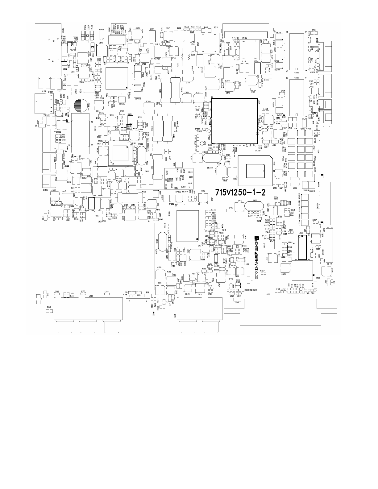
11. PCB Layout
11.1 Main Board
67
Page 68
68
Page 69
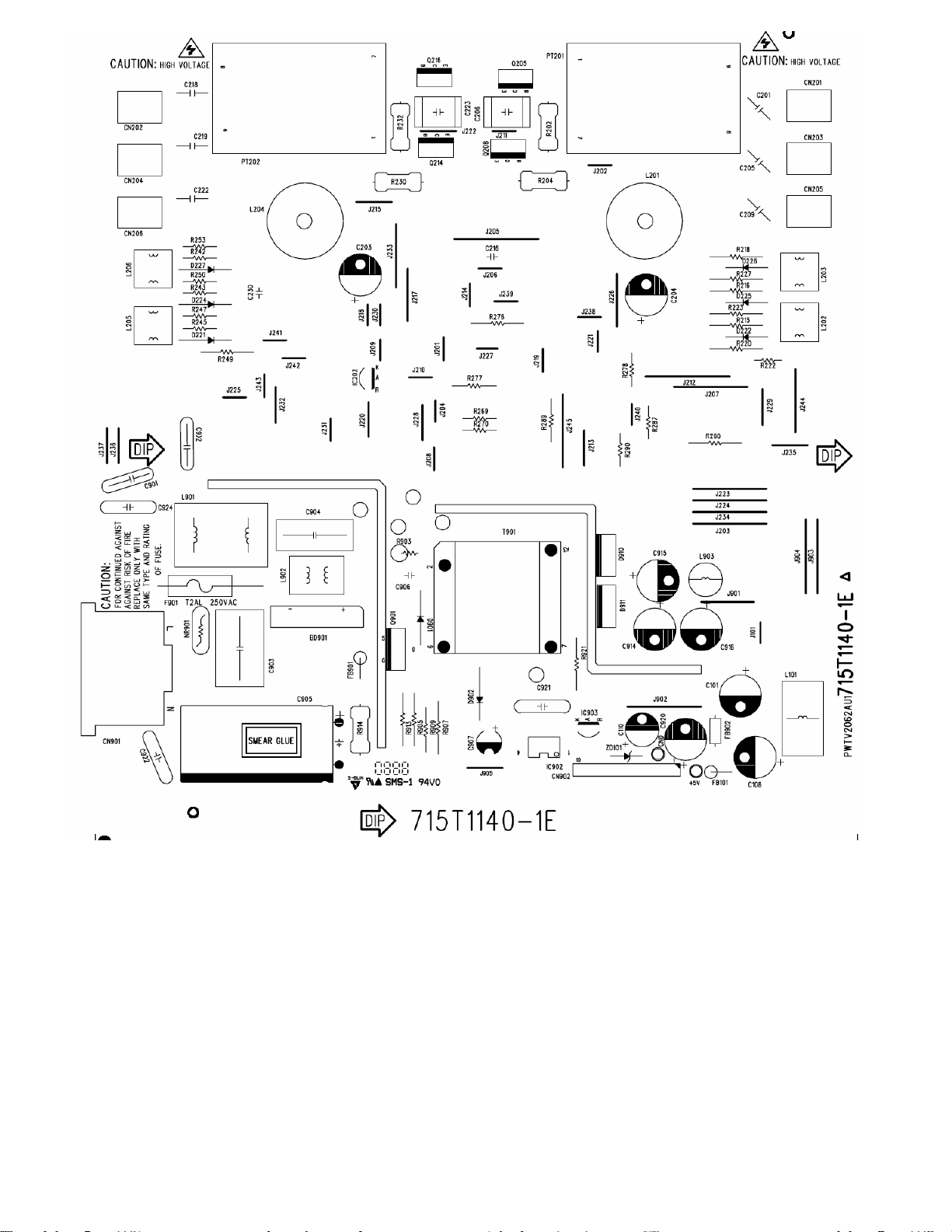
11.2 Power Board
69
Page 70
70
 Loading...