

Page 1
27’’ LCD TV Color Monitor Norcent LT2725
Service
Service
Service
Horizontal Frequency
31- 60 KHz
Description Page Description Page
Table Of Contents.......…….…..............................…........1
Revision List.…….….....................................……......2
Important Safety Notice.……..................……......3
1. Monitor Specification..…............................………........4
2. Operating Instructions……...……………….……….......5
2.1 The Use Of Remote Control..…………..................5
2.2 Front Panel Control Knobs.....................…...........6
2.3 OSD Operating…………….…............……...............7
2.4 How To Connect...………........................…............12
3. Input/Output Specification............……………............15
3.1 Input Signal Connector............………….................15
3.2 Factory Preset Display Modes........………...............16
4. Mechanical Instructions..………....……......................17
5. Repair Flow Chart…….……………………..................22
6. White Balance, Luminance Adjustment…...……….....25
7. PCB Layout………….....…………………...….…….....27
ANY PERSON ATTEMPTING TO SERVICE THIS CHASSIS MUST FAMILIARIZE HIMSELF WITH THE
TABLE OF CONTENTS
7.1 Main Board………….....……………………....….......27
7.2 Power Board………..….…………………….....….......29
7.3 Audio Board…………..…..........................…….........31
7.4 Key Board.......………..…...…...................................32
8. Block Diagram..…….…....................….......................33
8.1 Main Board.............………..……...............................33
8.2 Power Board….............……...….…..........................34
9. Schematic Diagram...……....….………………….......35
9.1 Main Board……...…..……..…………......................35
9.2 Power Board...…….….……….……………………...53
9.3 Audio Board...………………………..………………..54
9.4 Key Board......…...............…………........................55
9.5 IR Board...…….........………..…..............................56
9.6 Side Board……………………....…………………….57
10. Exploded View……...................................................58
11. BOM List……………….……………...……….…........59
SAFETY NOTICE
CHASSIS AND BE AWARE OF THE NECESSARY SAFETY PRECAUTIONS TO BE USED WHEN SERVICING
ELECTRONIC EQUIPMENT CONTAINING HIGH VOLTAGES.
CAUTION: USE A SEPARATE ISOLATION TRANSFOMER FOR THIS UNIT WHEN SERVICING
1
Page 2
27’’ LCD TV Color Monitor Norcent LT2725
Revision List
Version Release Date Revision History TPV Model
A00 Jun-05-2006 Initial Release E276MZNKD2NCNCP
A01 Nov-07-2006 Add TPV Model in item 11 E276MZNKD2NCNP
2
Page 3

27’’ LCD TV Color Monitor Norcent LT2725
Important Safety Notice
Proper service and repair is important to the safe, reliable operation of all AOC Company Equipment. The service
procedures recommended by AOC and described in this service manual are effective methods of performing service
operations. Some of these service operations require the use of tools specially designed for the purpose. The
special tools should be used when and as recommended.
It is important to note that this manual contains various CAUTIONS and NOTICES which should be carefully read in
order to minimize the risk of personal injury to service personnel. The possibility exists that improper service
methods may damage the equipment. It is also important to understand that these CAUTIONS and NOTICES ARE
NOT EXHAUSTIVE. AOC could not possibly know, evaluate and advise the service trade of all conceivable ways in
which service might be done or of the possible hazardous consequences of each way. Consequently, AOC has not
undertaken any such broad evaluation. Accordingly, a servicer who uses a service procedure or tool which is not
recommended by AOC must first satisfy himself thoroughly that neither his safety nor the safe operation of the
equipment will be jeopardized by the service method selected.
Hereafter throughout this manual, AOC Company will be referred to as AOC.
WARNING
Use of substitute replacement parts, which do not have the same, specified safety characteristics may create shock,
fire, or other hazards.
Under no circumstances should the original design be modified or altered without written permission from AOC.
AOC assumes no liability, express or implied, arising out of any unauthorized modification of design.
Servicer assumes all liability.
FOR PRODUCTS CONTAINING LASER:
DANGER-Invisible laser radiation when open AVOID DIRECT EXPOSURE TO BEAM.
CAUTION-Use of controls or adjustments or performance of procedures other than those specified herein may
result in hazardous radiation exposure.
CAUTION -The use of optical instruments with this product will increase eye hazard.
TO ENSURE THE CONTINUED RELIABILITY OF THIS PRODUCT, USE ONLY ORIGINAL MANUFACTURER'S
REPLACEMENT PARTS, WHICH ARE LISTED WITH THEIR PART NUMBERS IN THE PARTS LIST SECTION OF
THIS SERVICE MANUAL.
Take care during handling the LCD module with backlight unit
-Must mount the module using mounting holes arranged in four corners.
-Do not press on the panel, edge of the frame strongly or electric shock as this will result in damage to the screen.
-Do not scratch or press on the panel with any sharp objects, such as pencil or pen as this may result in damage to
the panel.
-Protect the module from the ESD as it may damage the electronic circuit (C-MOS).
-Make certain that treatment person’s body is grounded through wristband.
-Do not leave the module in high temperature and in areas of high humidity for a long time.
-Avoid contact with water as it may a short circuit within the module.
-If the surface of panel becomes dirty, please wipe it off with a soft material. (Cleaning with a dirty or rough cloth may
damage the panel.)
3
Page 4
27’’ LCD TV Color Monitor Norcent LT2725
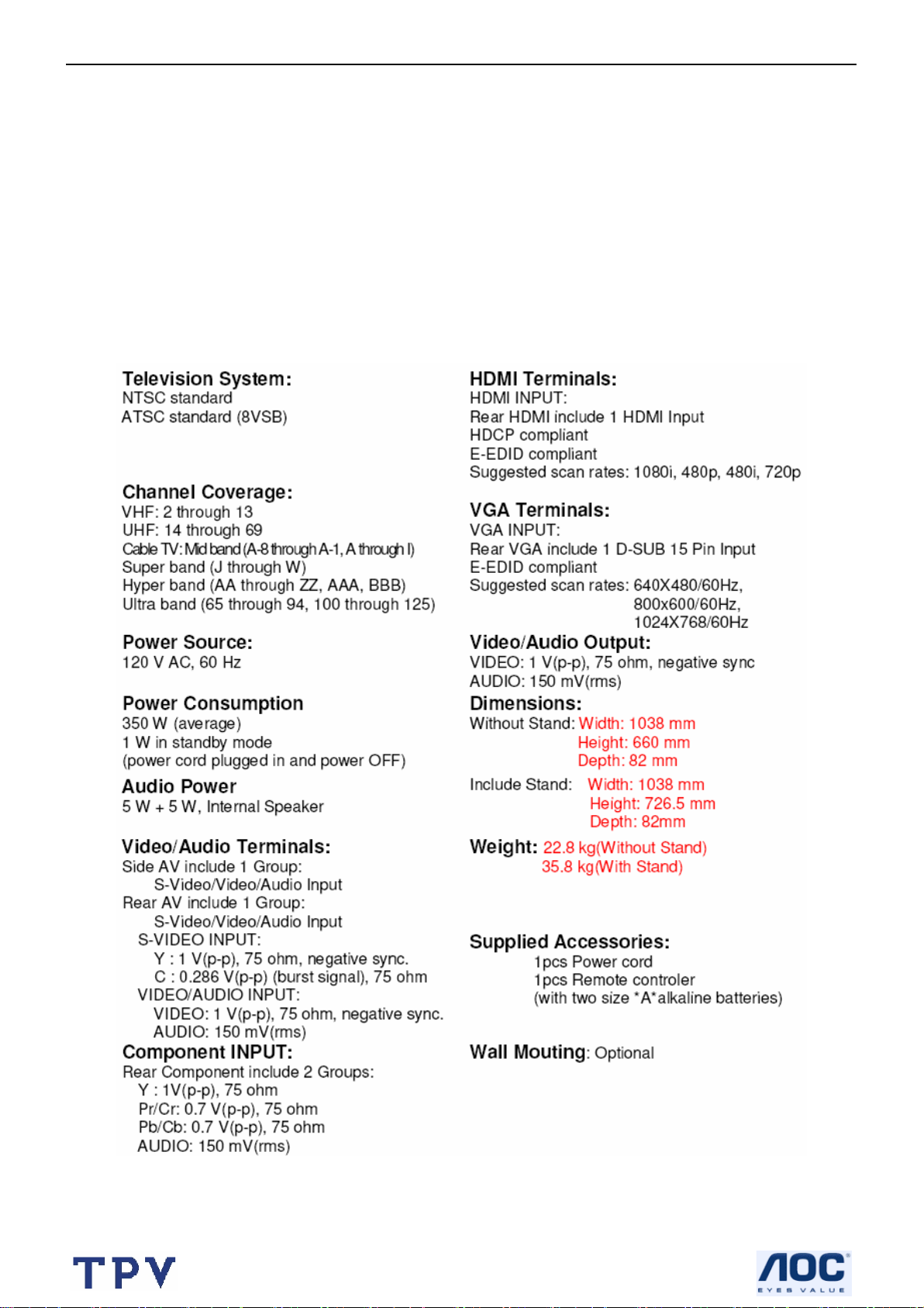
1. General Specifications
27” 16:9 LCD DISPLAY PANEL
Resolutions: 1366 (H) X 768 (V) pixels, (1 pixel = 1 R, G, B cells)
0.1460 mm (H) X 0.4365 mm(V) pixel pitch.
Panel MAX Brightness: 550 cd/m2 ㎡ , Panel MAX Contrast:1000:1
ATSC receiver, MPEG-2 decoder
NTSC receiver, Video decoder
Video, S-Video receiver
MIPS controller technology
Factory Presets
D-SUB Vertical refresh rate 56Hz to 75 Hz
D-SUB Horizontal frequency 31.5KHz to 64KHz
Universal Power Supply designed for worldwide application
UL, FCC, certification
≤150 W (Power consumption)
Closed Caption / V-chip For USA
4
Page 5
27’’ LCD TV Color Monitor Norcent LT2725
2. Operations Instructions
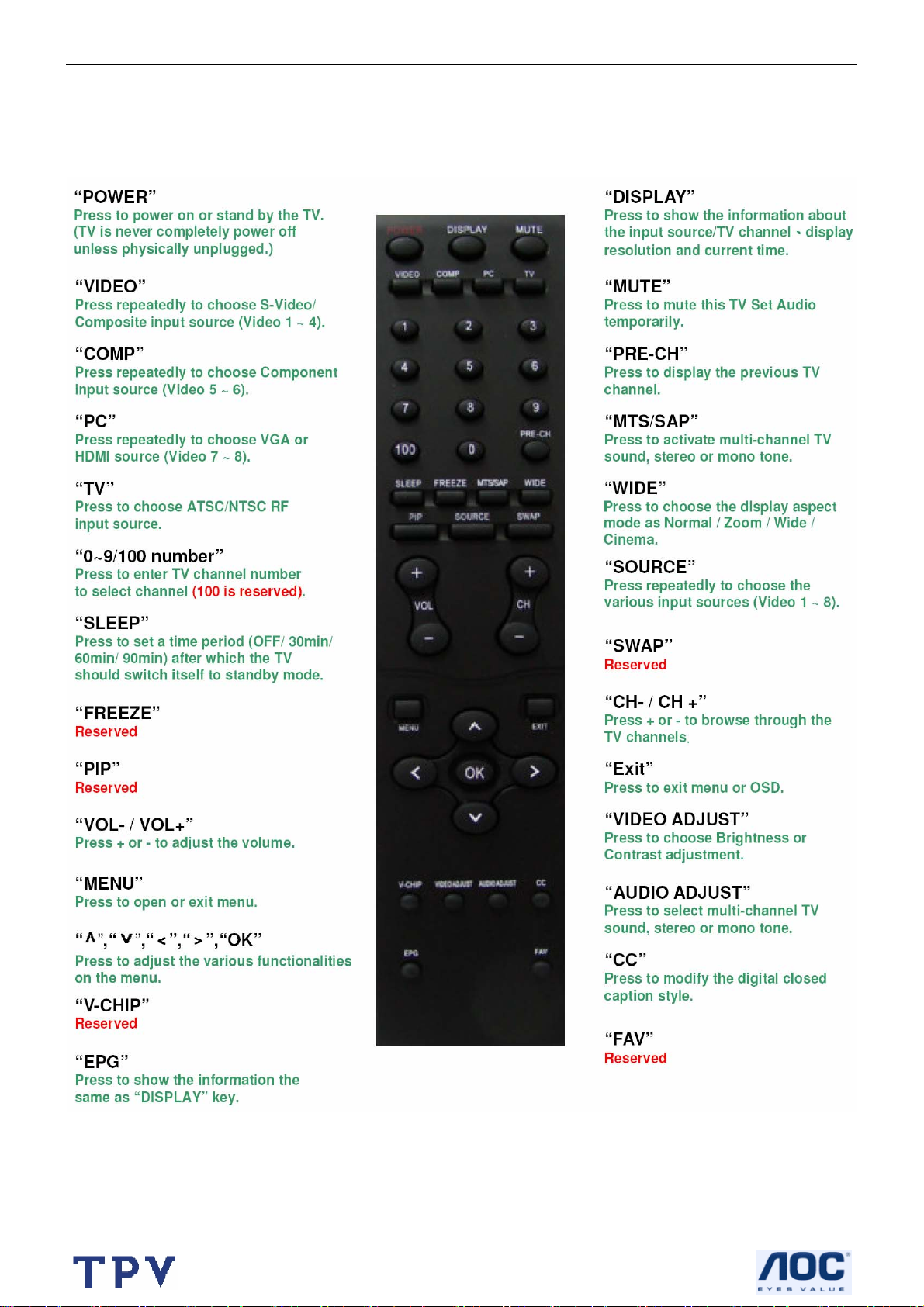
2.1 The Use Of Remote Control
Remote control button function as follow
5
Page 6
27’’ LCD TV Color Monitor Norcent LT2725
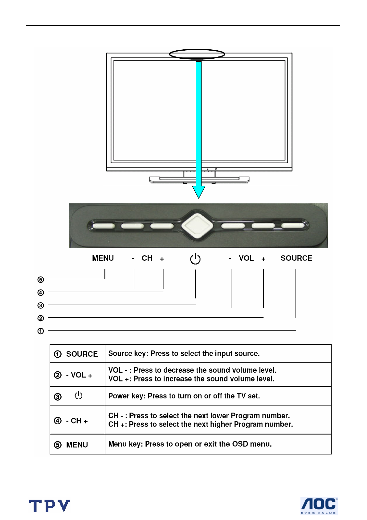
2.2 Front Panel Control Knobs
6
Page 7
27’’ LCD TV Color Monitor Norcent LT2725
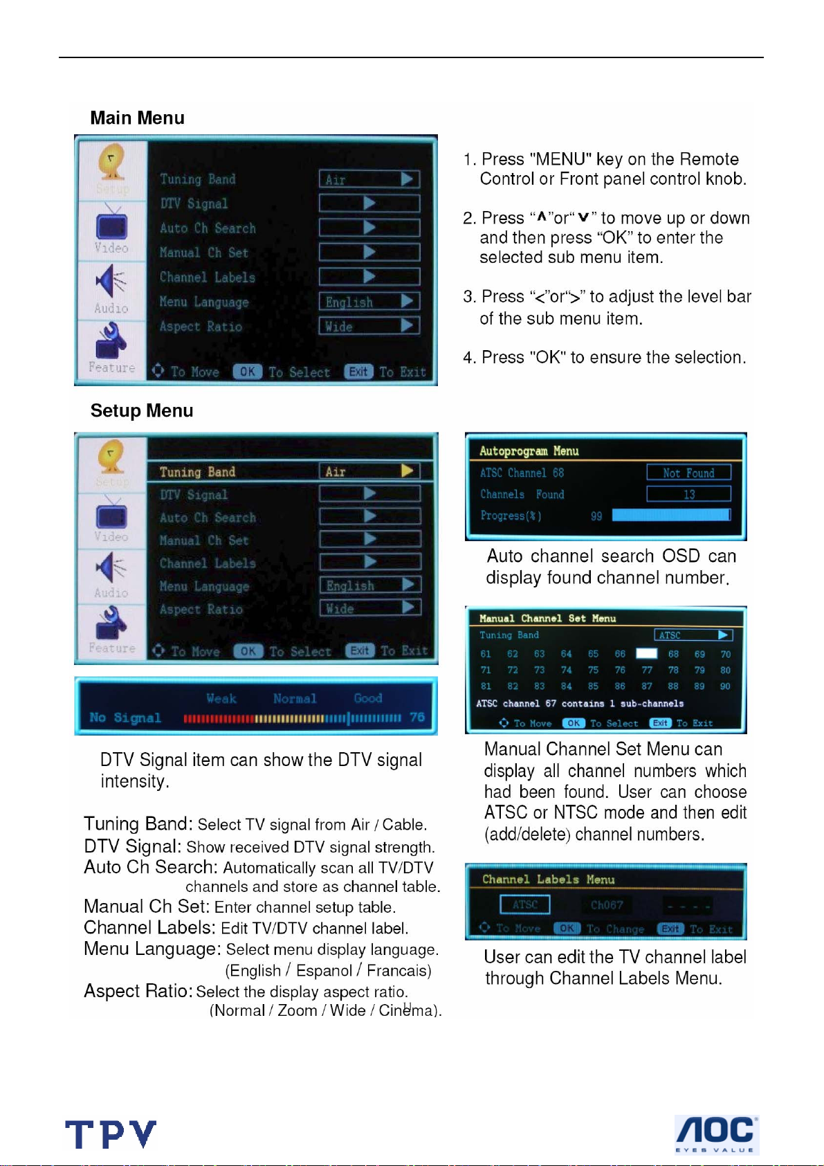
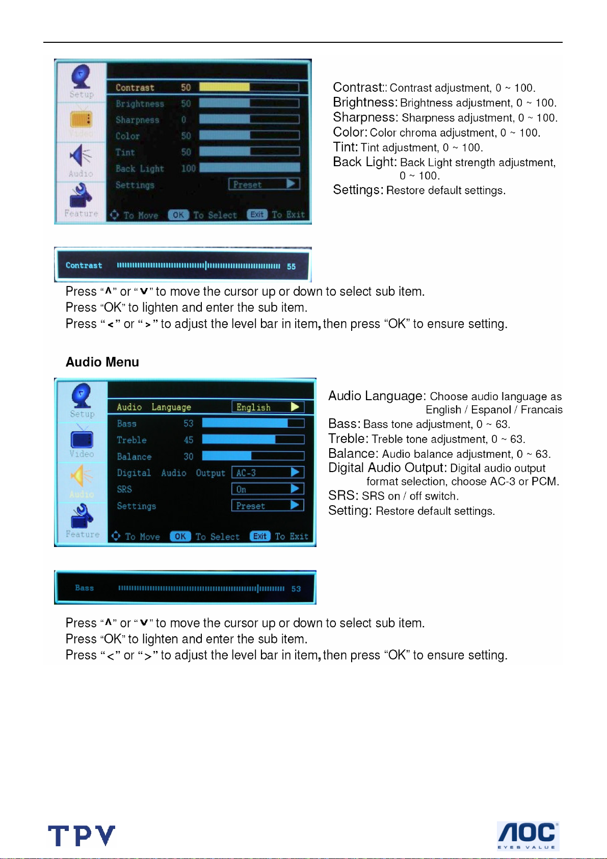
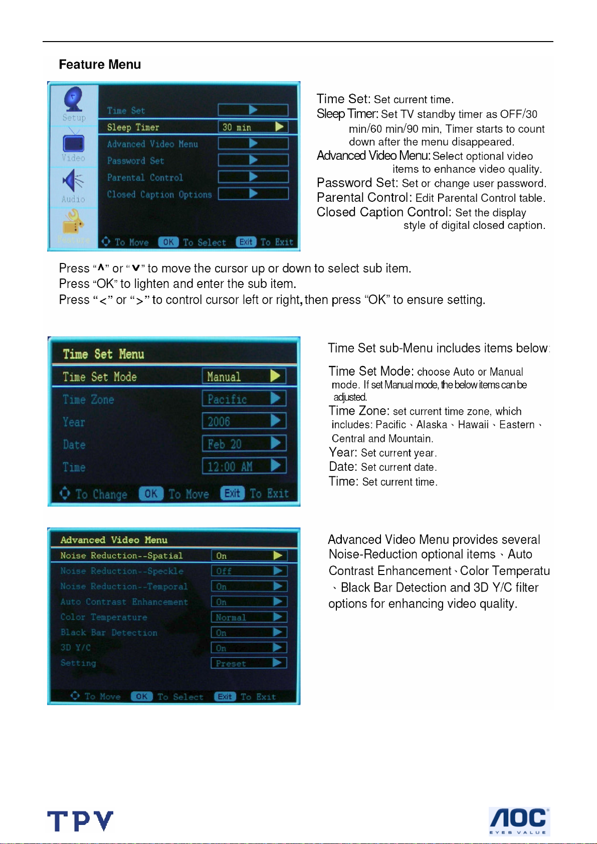
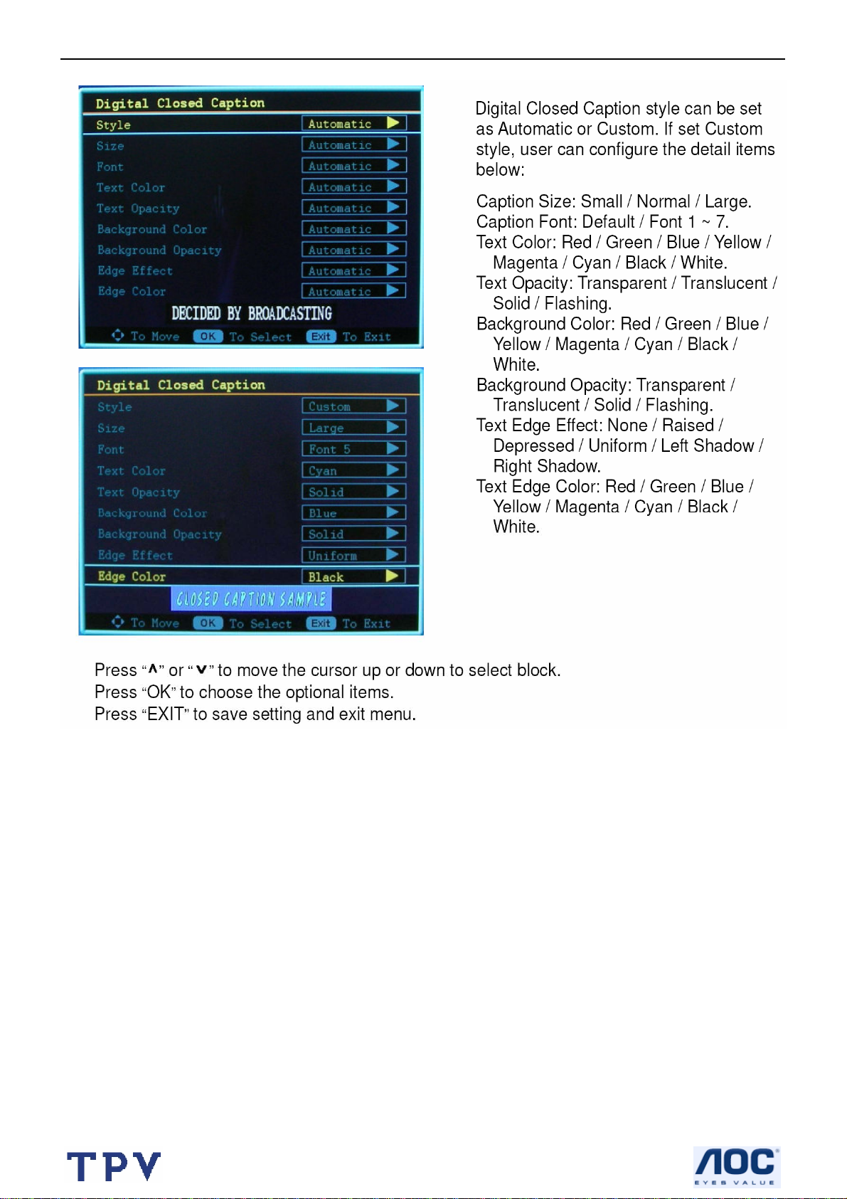
2.3 OSD Operations
7
Page 8
27’’ LCD TV Color Monitor Norcent LT2725
8
Page 9
27’’ LCD TV Color Monitor Norcent LT2725
9
Page 10

27’’ LCD TV Color Monitor Norcent LT2725
10
Page 11
27’’ LCD TV Color Monitor Norcent LT2725
11
Page 12
27’’ LCD TV Color Monitor Norcent LT2725
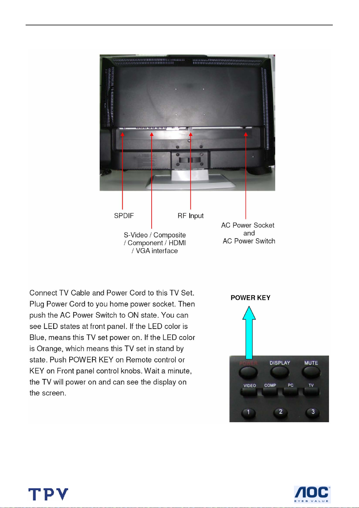
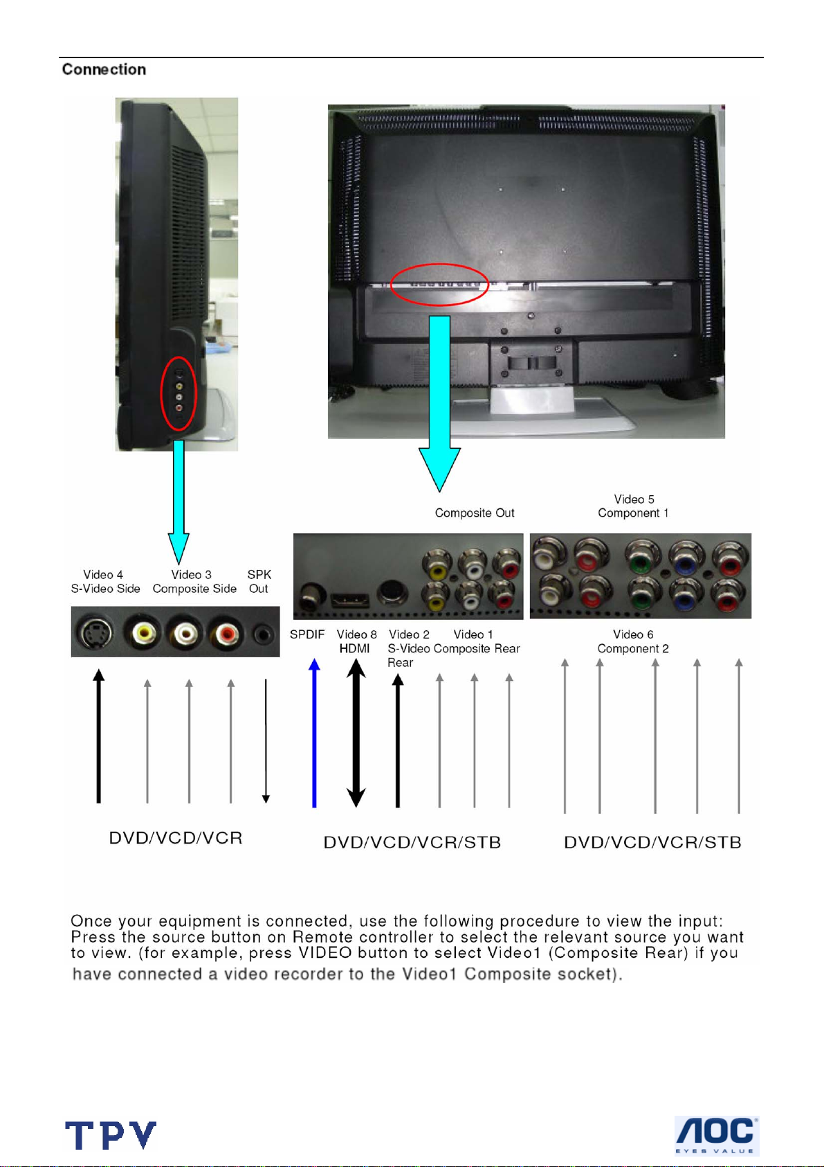
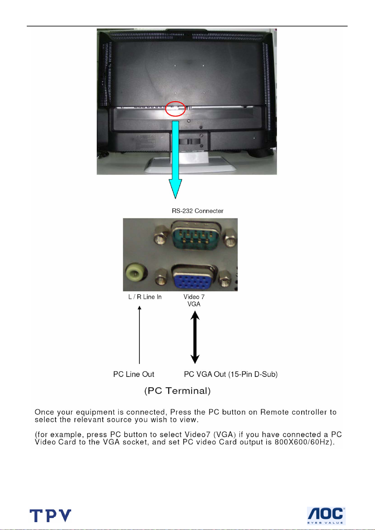
2.4 How To Connect
12
Page 13
27’’ LCD TV Color Monitor Norcent LT2725
13
Page 14
27’’ LCD TV Color Monitor Norcent LT2725
14
Page 15
27’’ LCD TV Color Monitor Norcent LT2725
3. Input/Output Specification
3.1 Input Signal connector
This procedure gives you instructions for installing and using the LCD TV display.
Lay the display on the desired operation and plug the power cord into a convenient AC outlet. Three-wire power cord
must be shielded and is provided as a safety precaution as it connects the chassis and cabinet to the electrical
conduct ground. If the AC outlet in your location does not have provisions for the grounded type plug, the installer
should attach the proper adapter to ensure a safe ground potential.
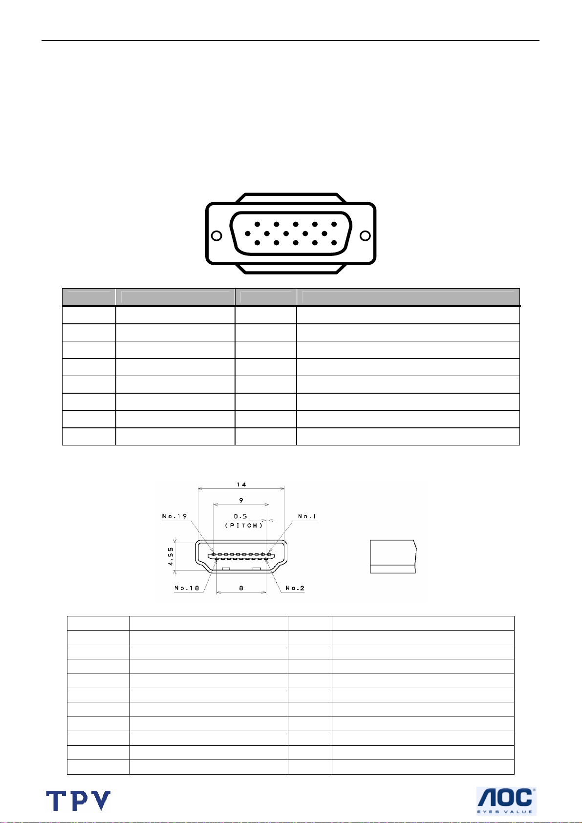
Connect the 15-pin D-SUB color display shielded signal cable to your signal system device and lock both screws on
the connector to ensure firm grounding. The connector information is as follow:
15 - Pin Color Display Signal Cable
6
Pin Signal Assignment Pin Signal Assignment
1 Red Video 9 No Pin!
2 Green Video 10 Sync. Ground
3 Blue Video 11 SDA (Remote Control)
4 SCL (Remote Control) 12 Serial Data for DDC
5 GROUND 13 Horizontal Sync.
6 Red Video Ground 14 Vertical Sync.
7 Green Video Ground 15 Serial Clock for DDC
8 Blue Video Ground
HDMI Digital connector pin assignments
1
11 15
5
10
Pin Signal Assignment Pin Signal Assignment
1 TMDS Data2+ 2 TMDS Data2 Shield
3 TMDS Data2- 4 TMDS Data1+
5 TMDS Data1 Shield 6 TMDS Data1-
7 TMDS Data0+ 8 TMDS Data0 Shield
9 TMDS Data0- 10 TMDS Clock+
11 TMDS Clock Shield 12 TMDS Clock-
13 CEC 14 NC
15 SCL 16 SDA
17 DDC/CEC Ground 18 +5V Power
19 Hot Plug Detect
15
Page 16
27’’ LCD TV Color Monitor Norcent LT2725
Apply power to the display by turning the power switch to the "ON" position and allow about ten seconds for Panel
warm-up. The Power-On indicator lights "GREEN" when the display is on.
With proper signals feed to the display, a pattern or data should appear on the screen, adjust the brightness and
contrast to the most pleasing display, or press auto-adjust to get the best picture-quality.
This TV (with PC function) has power saving function following the VESA DPMS. Be sure to connect the signal
cable to the PC.
If your TV requires service, it must be returned with the power cord.
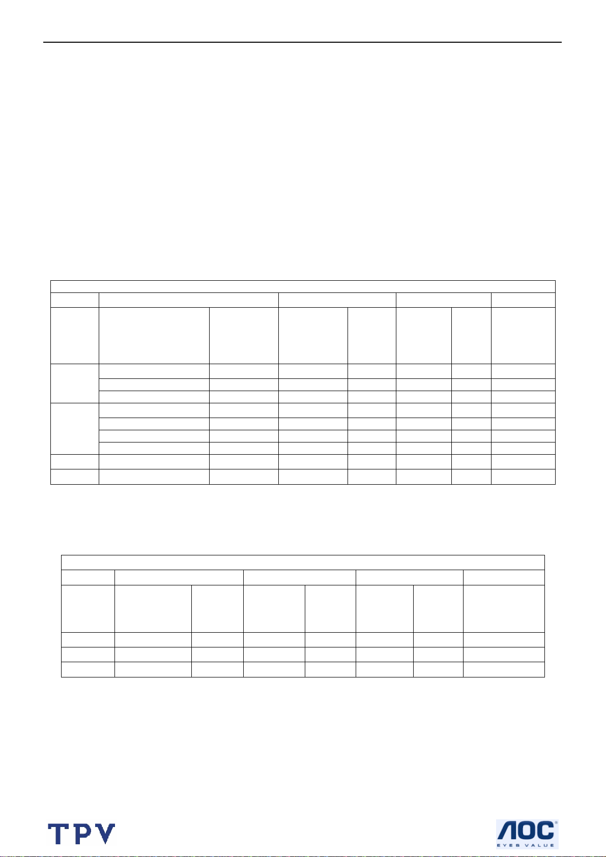
3.2 Factory Preset Display Modes:
Analog RGB input signal timing
VESA MODES
Horizontal Vertical
Nominal
Mode Resolution Total
640x480@60Hz 800 x 525 31.469 N 59.940 N 25.175
VGA
SVGA
XGA 1024x768@60Hz 1344x806 48.363 N 60.004 N 65.000
WXGA 1360x768@60Hz 1792x795 47.712 P 60.015 P 85.5
640x480@72Hz 832 x 520 37.861 N 72.809 N 31.500
640x480@75Hz 840 x 500 37.5 N 75 N 31.500
800x600@56Hz 1024 x 625 35.156 P 56.25 P 36.000
800x600@60Hz 1056 x 628 37.879 P 60.317 P 40.000
800x600@72Hz 1040 x 666 48.097 P 72.188 P 40.000
800x600@75Hz 1056 x 625 460875 P 75 P 49.5
Frequency
(KHz)
Sync
Polarity
Nominal
Freq.
(Hz)
Sync
Polari
ty
Nominal
Pixel
Clock
(MHz)
HDMI input signal timing
VESA MODES
Mode Resolution Total
720P
1080i
480P
1280×720P
1920X1080i 33.75 60 74.25
720X480P 31.54 60 27.00
45.00 60 74.25
Horizontal Vertical
Nominal
Frequency
(KHz)
Polarity
Sync
Nominal
Freq.
(Hz)
Sync
Polarity
Nominal
Pixel
Clock
(MHz)
16
Page 17
27’’ LCD TV Color Monitor Norcent LT2725
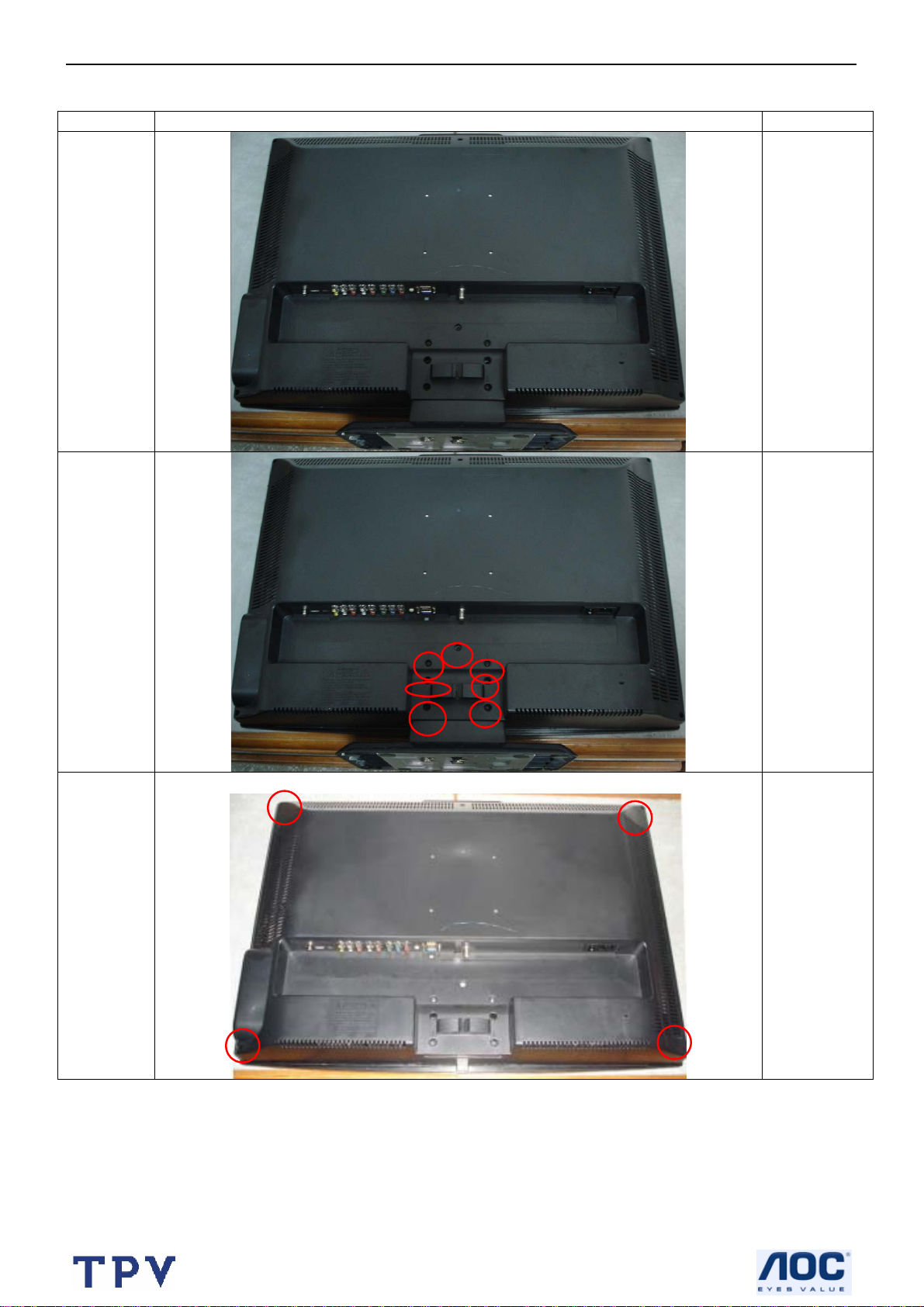
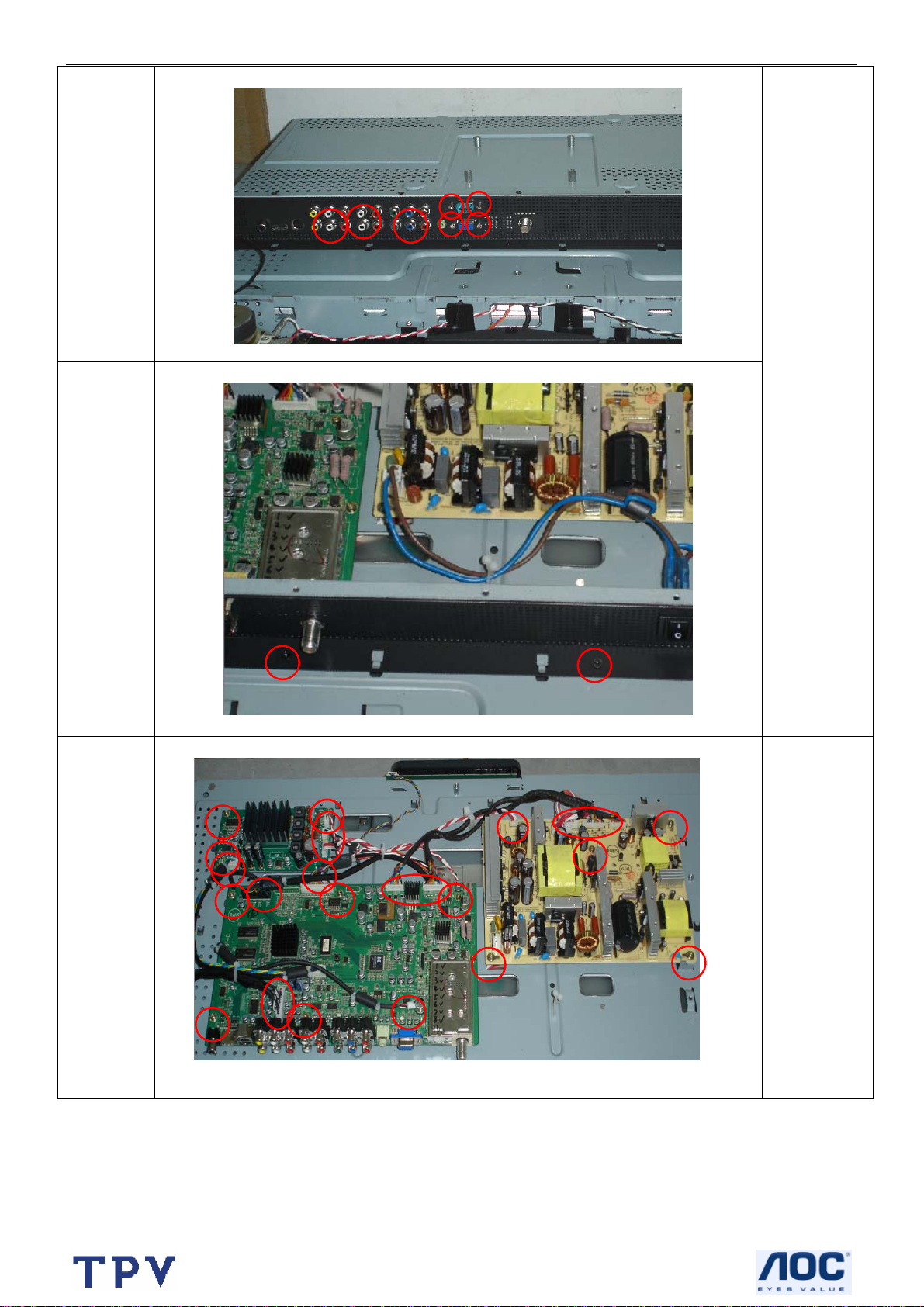
4. Mechanical Instructions
Step Figure Description
Lay the
LCD-TV on a
Preparation
flat, soft and
clean
surface.
Remove
base
Remove
back cover
Remove
seven screws
Remove four
screws
17
Page 18
27’’ LCD TV Color Monitor Norcent LT2725
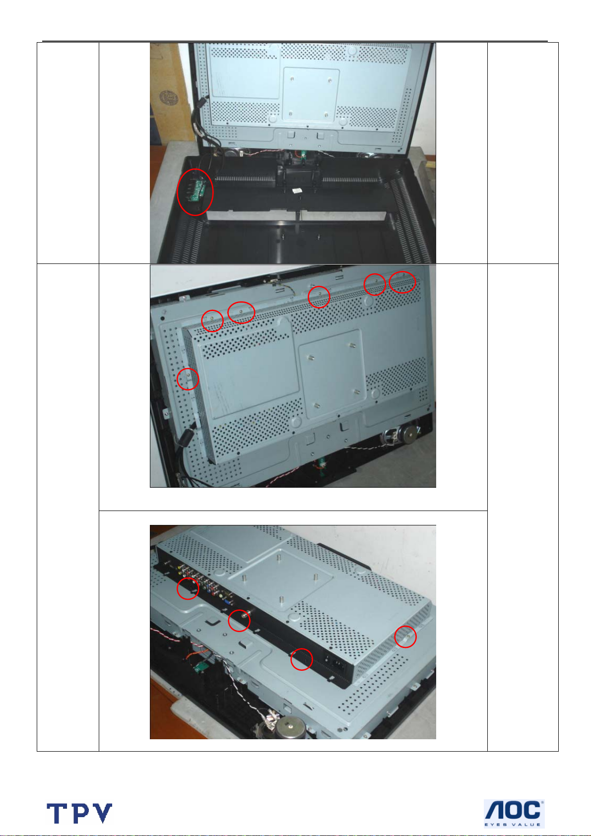
Remove
shield
Remove
connector
Remove
fifteen
screws
18
Page 19
27’’ LCD TV Color Monitor Norcent LT2725
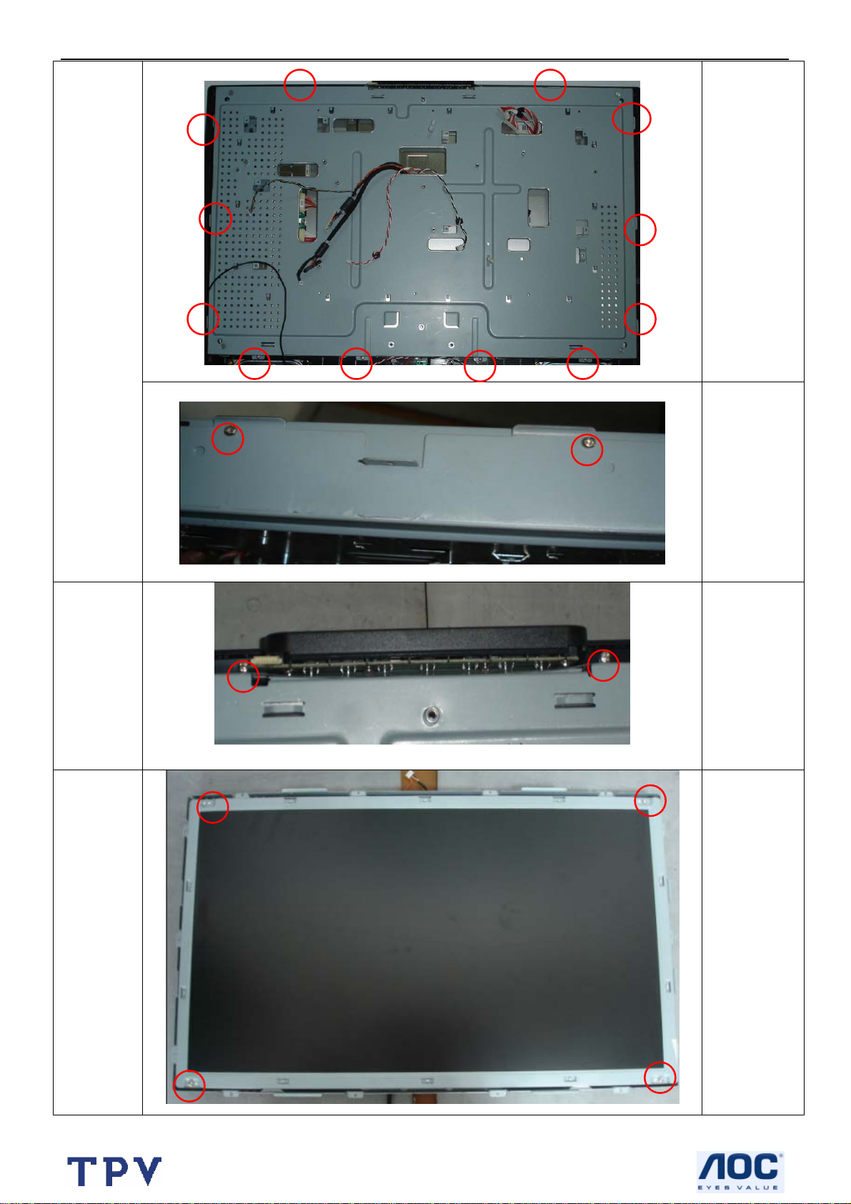
Remove
Main,
power
and Audio
board
19
Remove
screws and
disconnect
the wire
harness
Page 20
27’’ LCD TV Color Monitor Norcent LT2725
Remove
twelve
screws
Remove
main frame
Remove
key board
Remove four
screws (left
and right)
Remove two
screws
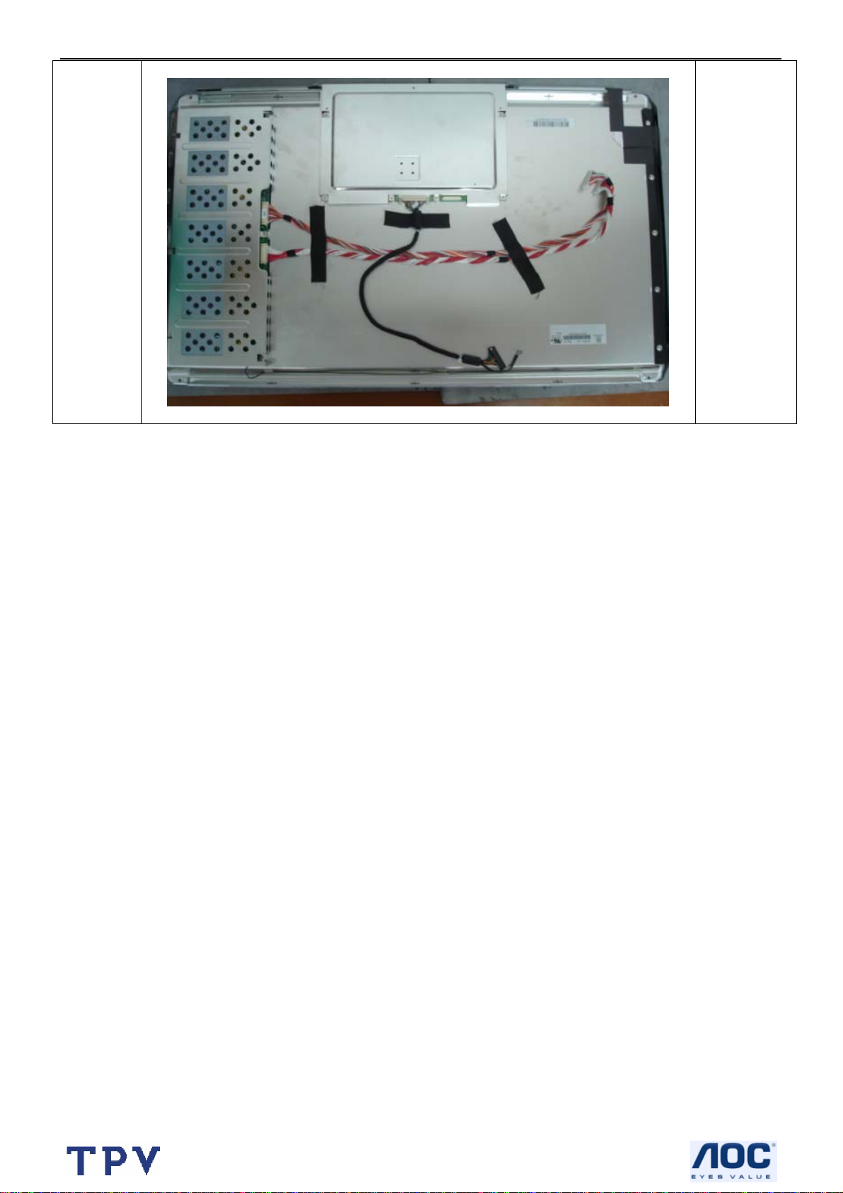
Remove
panel
20
Remove four
screws
Page 21
27’’ LCD TV Color Monitor Norcent LT2725
21
Page 22
27’’ LCD TV Color Monitor Norcent LT2725
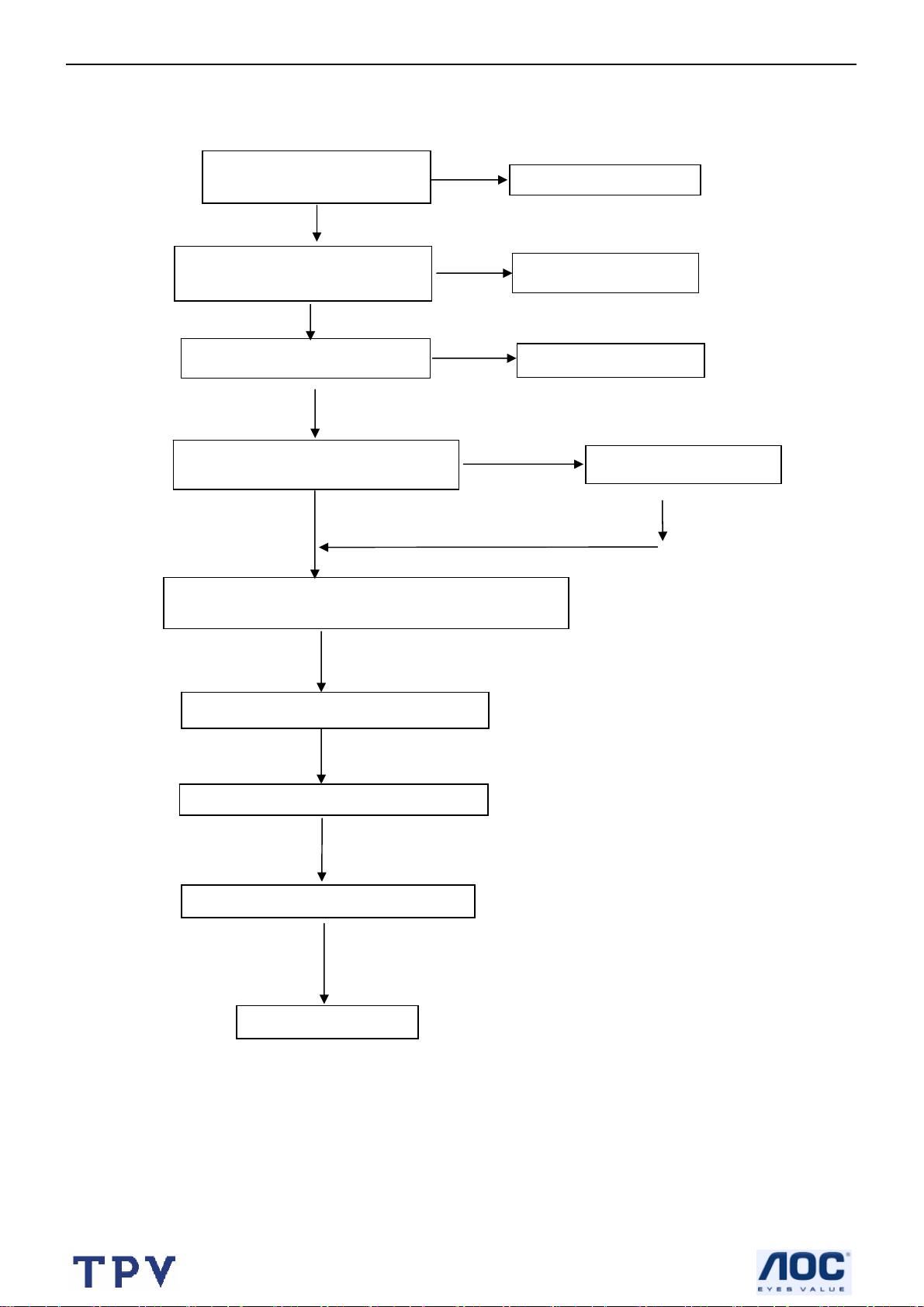
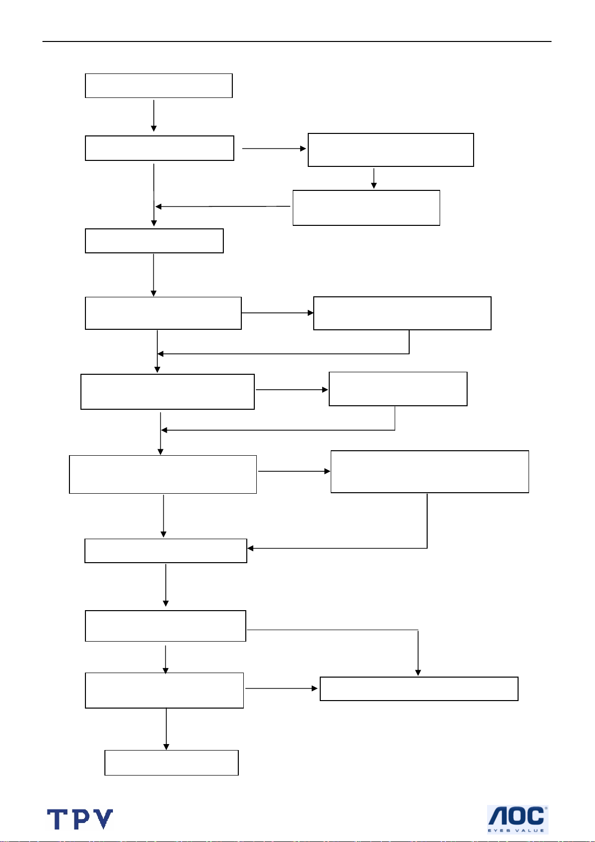
5. Repair Flow Chart
5.1 Abnormal display
CHECK CON901 PIN9=12V
CON905 PIN3=5V?
NG
Check POWER BOARD
OK
CHECK CN407 PANEL connect is
normal?
NG
Reconnect CN407
OK
CHECK X401、X701 is normal?
NG
Check surge circuit
OK
CHECK U401 PIN R5、PIN T8=3.3V?
U401 PIN E6=2.5V? PIN R9=1.8V?
OK
CHECK U108 PIN18, PIN17, PIN14 output wave is OK;
PIN9 PIN20 power supply is OK?
OK
CHECK I²C1DATA, CLK is normal?
OK
CHECK SCALER HS VS is normal?
OK
Check TV mode display is normal?
NG
OK
CHECK SCALER power
OK
Check Tuner circuit
22
Page 23
27’’ LCD TV Color Monitor Norcent LT2725
pply
5.2 No sound
Check speakers are ok?
OK
Check earphone is normal?
OK
Check Q2 MUTE circuit
OK
Test NJM2199 (U5) PIN 12 PIN
11 output is normal?
Test TC200 (U2) PIN9 PIN10 PIN11
PIN 12 is normal
OK
OK
OK
NG
NG
Check TPA6110A2 (U600)
Relative circuit is normal?
Check CS4335 (U405) PIN5
PIN 8 output is normal?
Check NJM2199 (U5) PIN8 power
supply is normal?
OK
NG
OK
Check TC200 (U2) PIN21
power supply is normal?
Test TP2050 (U1) PIN17 PIN10 PIN8
PIN2 Output is normal?
CHECK X701 surge is normal?
Check CAS-220/CS (U701) is
normal?
Check SF701 PIN5、4 signal
input is normal?
OK
OK
OK
OK
NG
NG
Check TP2050 (U1) PIN15 PIN7 PIN4
power supply is 20V; PIN23 PIN25 power
su
is 5V?
OK
NG
Check ZR39660BGCG (U401) is normal?
Check TUNER circuit
23
Page 24
27’’ LCD TV Color Monitor Norcent LT2725
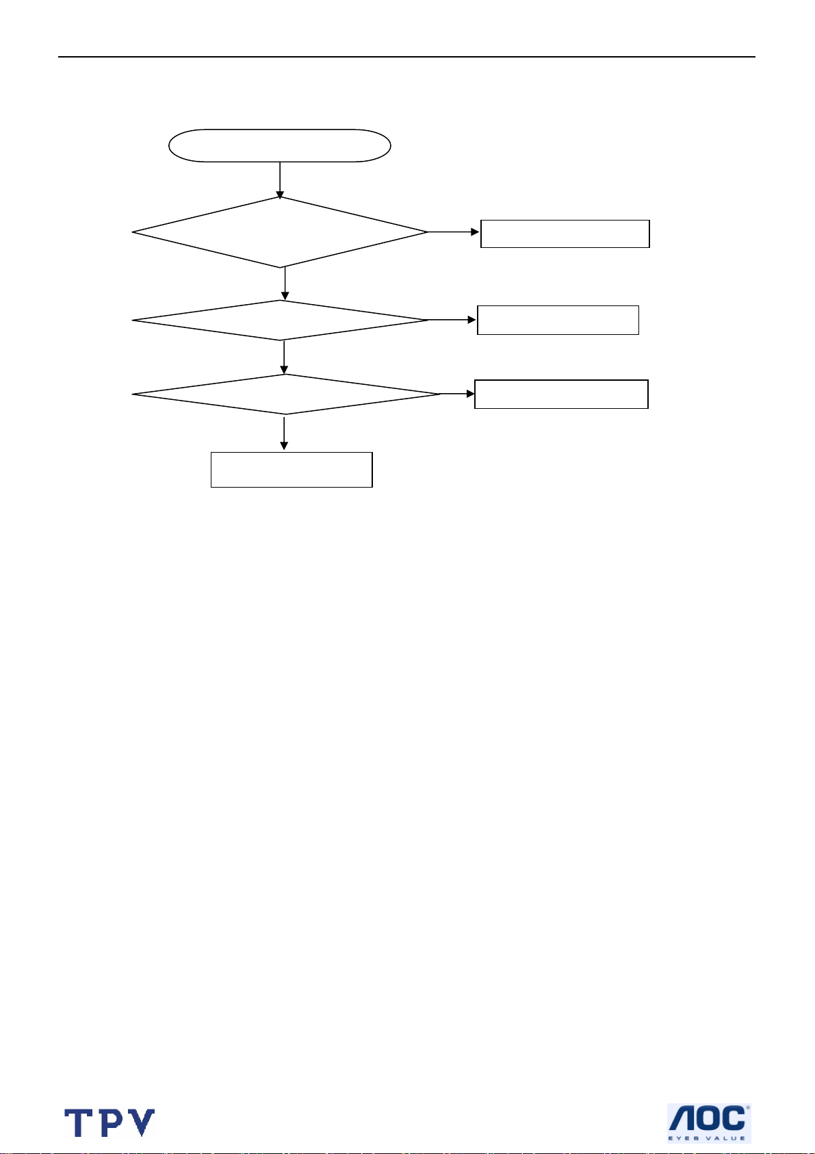
5.3 Key Board
OSD is unstable or not working
N
Is Key Pad Board connecting normally?
Y
Connect Key Pad Board
Is Button Switch normally?
Y
Is Key Pad Board Normally?
Y
Check Main Board
N
N
Replace Button Switch
Replace Key Pad Board
24
Page 25
27’’ LCD TV Color Monitor Norcent LT2725
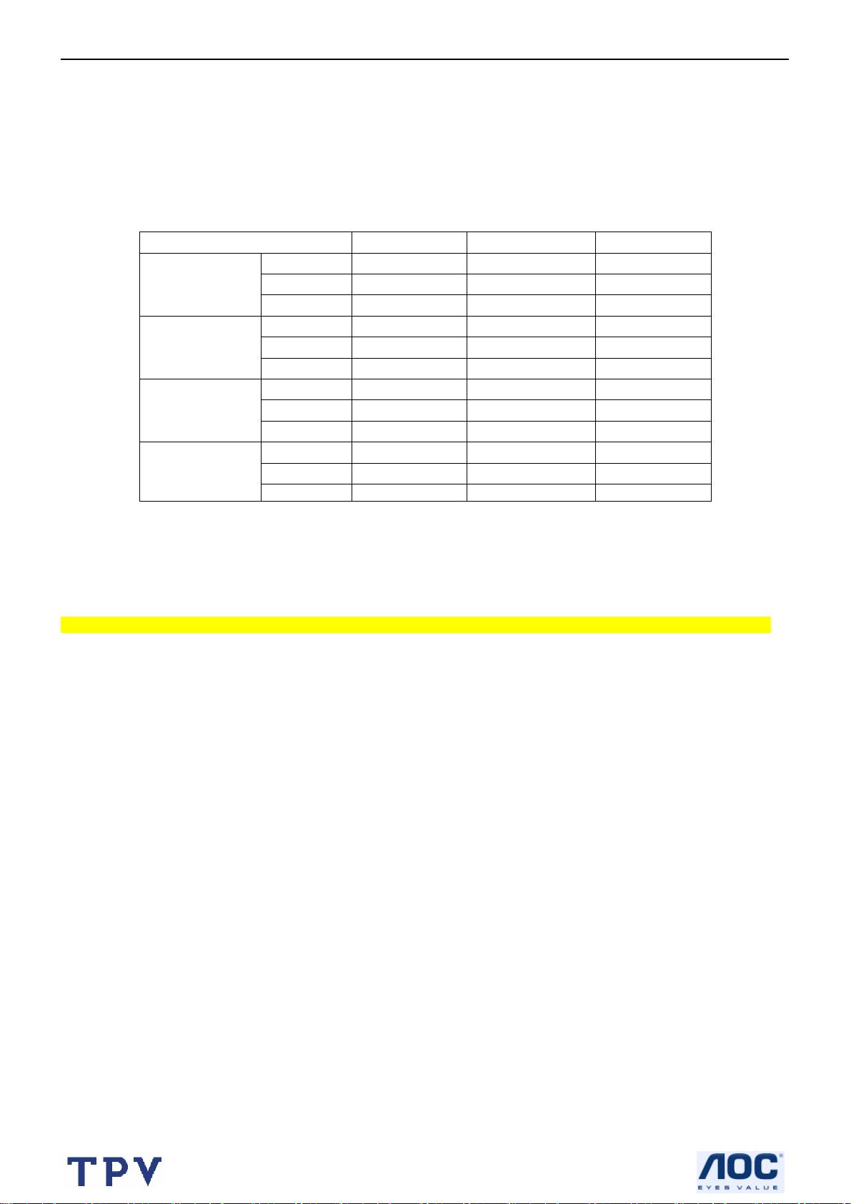
6. White Balance, Luminance Adjustment
Approximately 30 minutes should be allowed for warm up before proceeding white balance adjustment.
First adjust PC mode and then adjust AV mode, HDMI mode, component 480i mode, component 480p mode. Before
started adjust white balance, please set the Chroma-7120 MEM. Channel 01 to Cold color MEM. and channel 03 to
Normal color, MEM. and channel 04 to warm color, MEM.(Our cold parameter is x = 291, y =306; normal parameter
is x =299, y =315; warm parameter is x =308, y =325)
Color Temp. Cold Normal Warm
x 291 299 308
PC MODE
AV MODE
HDMI
COMPONENT
(480i/480p)
Note: The tolerance of the color coordinates should be less than ± 20.
How to setting MEM. channel you can reference to Chroma-7120 user guide or simple use “ SC” key and “ NEXT”
key to modify x, y , Y value and use “ID” key to modify the TEXT description
Following is the procedure to do white-balance adjust
Note: Step of AV, HDMI, COMPONENT480i, COMPONENT480p mode adjustment is the s ame as PC mode,
PC mode:
Ⅰ. In the TV mode adjust volume to zero and press number key 9 Æ 8 Æ 7 Æ 6. It will achieve the
factory mode. Select the item of White Balance and press right key to enter it.
In the White Balance you can adjust 8 items.
1-3 items is RO, GO, BO Æ R, G, B Bias adjust.
4-6 items is RG, GG, BG Æ R, G, B Gain adjust.
7 item needn’t adjust
8 items is color temperature select: Cool, Normal, and Warm.
Ⅱ. Bias (Low luminance) adjustment:
1. Set the raster pattern (Black pattern with 1024×768) Input.
2. Adjust the brightness on OSD until chroma 7120 measurement reach the lowest value.
Ⅲ. Gain adjustment:
A. Adjust Cold color-temperature:
1. Set the Contrast of OSD function to 80 and Adjust Brightness to chroma-7120 Y>350 cd/m2
2. Switch the chroma-7120 to RGB-mode (with press “MODE” button)
3. Switch the MEM. channel to Channel 01 (with up or down arrow on chroma-7120)
4. The LCD-indicator on chroma-7120 will show x =291, y =306, Y>350cd/m2
5. Adjust the 4 item: RG, until chroma 7120 indicator reached the value R=100
6. Adjust the 5 item: GG, until chroma-7120 indicator reached the value G=100
7. Adjust the 6 item: BG, until chroma-7120 indicator reached the value B=100
8. Repeat above procedure until chroma-7120 RGB value meet the tolerance =100±2
9. Switch the chroma-7120 to x, y, Y mode with press “MODE” button to check the color temp is in SPEC. or not.
10. Enter the 8 item to select another color temperature to adjust.
y 306 315 325
Y 350 350 350
x 291 299 308
y 306 315 325
Y 450 450 450
x 291 299 308
y 306 315 325
Y 420 420 420
x 291 299 308
y 306 315 325
Y 450 450 450
25
Page 26

27’’ LCD TV Color Monitor Norcent LT2725
B. Adjust Normal color-temperature:
1. Set the Contrast of OSD function to 80 and Adjust Brightness to chroma-7120 Y>350cd/m2
2. Switch the chroma-7120 to RGB-mode (with press “MODE” button)
3. Switch the MEM. channel to Channel 03 (with up or down arrow on chroma-7120)
4. The LCD-indicator on chroma-7120 will show x =299, y =315, Y>350cd/m2
5. Adjust the 4 item: RG, until chroma 7120 indicator reached the value R=100
6. Adjust the 5 item: GG, until chroma-7120 indicator reached the value G=100
7. Adjust the 6 item: BG, until chroma-7120 indicator reached the value B=100
8. Repeat above procedure until chroma-7120 RGB value meet the tolerance =100±2
9. Switch the chroma-7120 to x, y, Y mode With press “MODE” button to check the color temp is in SPEC. or not.
10. Enter the 8 item to select another color temperature to adjust.
C. Adjust Warm color-temperature:
1. Set the Contrast of OSD function to 80 and Adjust Brightness to chroma-7120 Y>350cd/m2
2. Switch the chroma-7120 to RGB-mode (with press “MODE” button)
3. Switch the MEM. channel to Channel 04 (with up or down arrow on chroma-7120)
4. The LCD-indicator on chroma-7120 will show x =308, y =324, Y>350cd/m2
5. Adjust the 4 item: RG, until chroma 7120 indicator reached the value R=100
6. Adjust the 5 item: GG, until chroma-7120 indicator reached the value G=100
7. Adjust the 6 item: BG, until chroma-7120 indicator reached the value B=100
8. Repeat above procedure until chroma-7120 RGB value meet the tolerance =100±2
9. Switch the chroma-7120 to x, y, Y mode With press “MODE” button to check the color temp is in SPEC. or not.
10. Enter the 8 item to select another color temperature to adjust.
Ⅳ.Switch different source:
Press the source key on the remote control to switch different source to adjust the AV, HDMI, CONPONENT 480i
and COMPONENT 480p mode.
Press “Exit” button on remote control to quit from factory mode.
26
Page 27
27’’ LCD TV Color Monitor Norcent LT2725
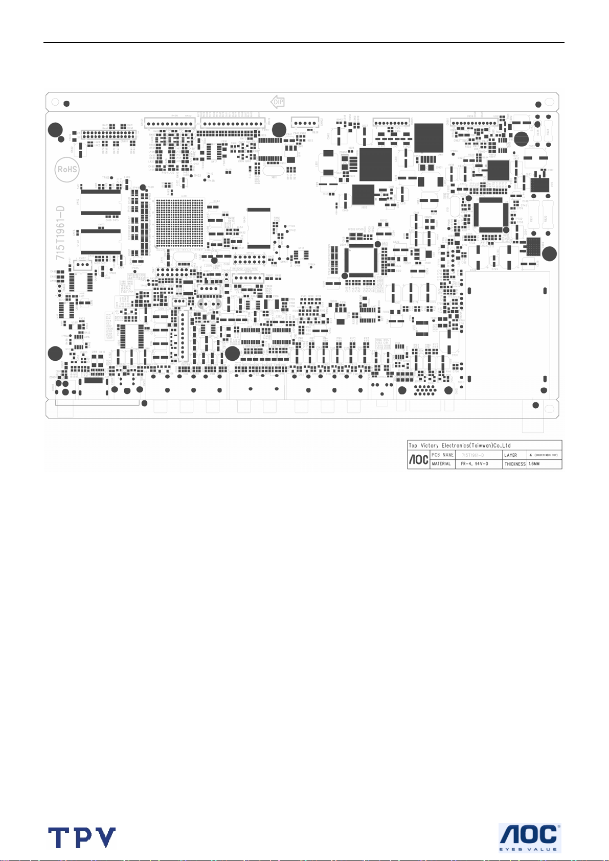
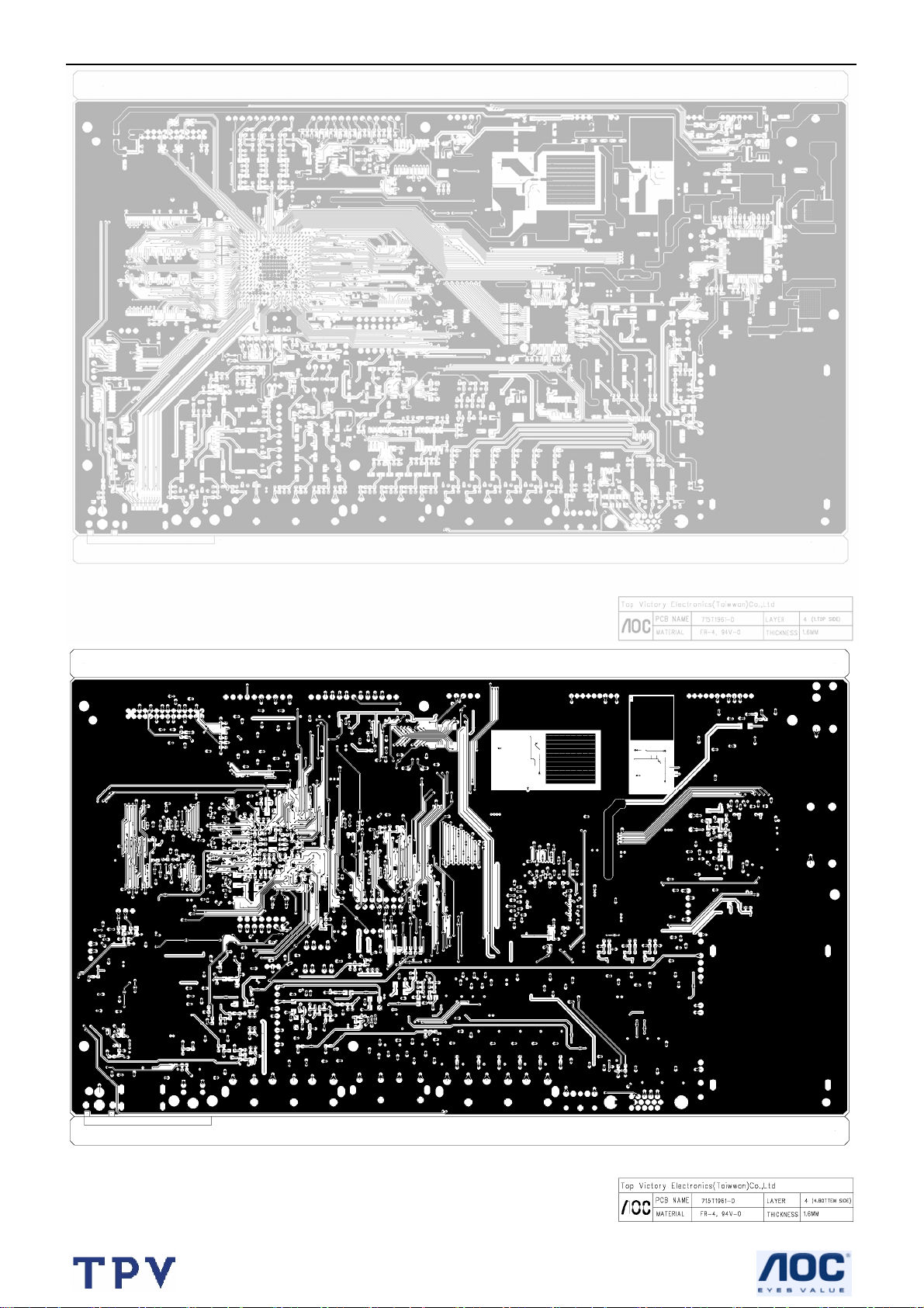
7. PCB Layout
7.1 Main Board
27
Page 28
27’’ LCD TV Color Monitor Norcent LT2725
28
Page 29
27’’ LCD TV Color Monitor Norcent LT2725
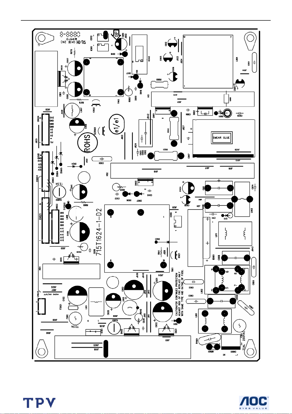
7.2 Power Board
29
Page 30
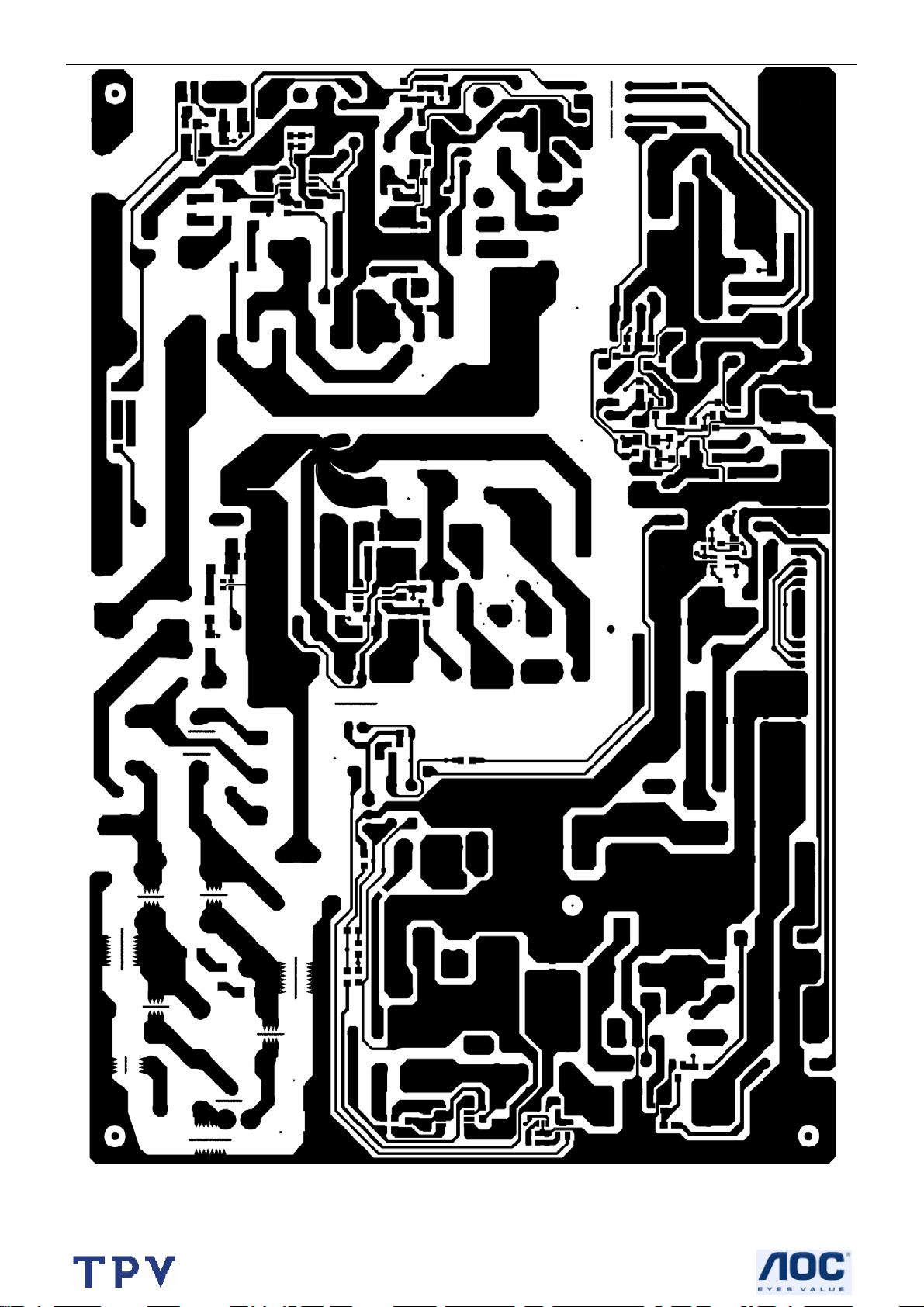
27’’ LCD TV Color Monitor Norcent LT2725
30
Page 31

27’’ LCD TV Color Monitor Norcent LT2725
7.3 Audio Board
715T1964 D
31
Page 32

27’’ LCD TV Color Monitor Norcent LT2725
7.4 Key Board
32
Page 33

27’’ LCD TV Color Monitor Norcent LT2725
8. Block Diagram
8.1 Main board
33
Page 34

27’’ LCD TV Color Monitor Norcent LT2725
(
)
8.2 Power Board
For Panel
12V 2.5A (max)
For Inverter
24V 4.5A (max)
EMI
CHOKE
Bridge
6A/800V
PFC
FA5500AN
Main Power
NCP1377BDR2G
OCP/OVP function option:
1. Latch
2. Auto restart
Audio OCP & SCP by using fuse
PS
ON/OFF
Standby Power
Sanken STR-A6252
DC/DC
5VS
PS
ON/OFF
For Audio
13V~22V Option
14~33W
For M/B,
TUNER
5V 3A
max
Standby mode <1W @5VS_ 50mA & 240VAC
34
Page 35

27’’ LCD TV Color Monitor Norcent LT2725
9. Schematic Diagram
9.1 Main Board
TV1_CVBS9
VCC5_0_T1
VCC5_0_T2
I2C0CLK6,12
I2C0DATA6,12
TU701
TUNER
RF AGC
AGC out
+5V
1
2
R708 47K
R709 10K 1/16W
C712
22pF
C718
0.01uF
I2C0CLK
I2C0DATA
4
R720
68
VT
C713
22pF
VCC5_0
R717
2K
R722
2K
AUDIO
SCL
SDA
IF out
CVBS
+5V
9
6573101112
8
FB703 600 OHM
FB704 600 OHM
FB705 600 OHM
680
R718
C720
0.01uF
C721
0.01uF
GND
GND
GND
GND
FM IF
SIF
C706 0.1uF
L711 330nH
C727
C729
47pF
82pF
12
L706
1uH
C719
Q701
BFR93A
R723
68
13
14
15
16
12
12
L710 330nH
0.01uF
TU_SDA
TU_SCK
C716
0.001uF
SIF
C717
0.1uF
SF701 X6941D
1
INPUT
2
INPUT
IF
Filter
C728
47pF
3
OUTPUT
OUTPUT
GND
C709
0.01uF
5
4
470uF/16V
IF_AGC
R715 3.9K
L707 1.8uH
VCC5_0
+
C733
C710
0.01uF
C714
NC/ 1pF
C724
10uF/16V
4
2
3
1
U702
VAGC
IN1
IN2
Vcc
UPC3218GV
C707
0.1uF
* Do notinstall.
+
OUT1
OUT2
GND
GND
C708
0.001uF
C725
0.0015uF
C701
0.01uF
6
7
8
5
FB702
600 OHM
C726
560pF
C704
0.01uF
R702 100
12
FB701 600 OHM
FB706 600 OHM
R701
100
L701
220nH
VCC5_0
VCC3V3_DM
VCC3V3_DM
Tuner / Demodulator
U701A
94
AIN2_P
C705
0.1uF
+
C736
0.001uF
R719 1M
C722
22pF
C731
470uF/16V
93
97
96
4
10
14
21
25
27
31
38
42
47
89
90
100
1
58
59
20
19
16
18
13
61
2
8
80
79
R721 100
AIN2_N
AIN1_P
AIN1_N
D_IN0
D_IN1
D_IN2
D_IN3
D_IN4
D_IN5
D_IN6
D_IN7
D_IN8
D_IN9
AIN_OOB_P
AIN_OOB_N
PARAM0
PARAM1
PARAM2
PARAM3
SDA_I2C
SCL_I2C
TU_SDA
TU_SCL
I2C_ADDR
RST
SCAN_EN
SCAN_MODE
XTI
XTO
C702
56pF
C703
R703
47 1/16W
SIF
0.1uF
I2C0DATA
I2C0CLK
TU_SDA
TU_SCK
OREN_RST3
C737
C734
0.1uF
0.1uF
47pF
C711
R725 10K 1/16W
R714 10K 1/16W
C735
0.001uF
CAS-220/CS
X701
25MHz
+
C732
470uF/16V
OREN
Demodulator
C723
22pF
VCC5_0_T1
VCC5_0_T2
VCC5_0_T2
36
D_OUT0
39
D_OUT1
40
D_OUT2
41
D_OUT3
43
D_OUT4
44
D_OUT5
48
D_OUT6
49
D_OUT7
29
D_VALID
34
D_SOP
28
D_CLK
32
D_FAIL
24
STAT0
26
STAT1
50
STAT2
51
STAT3
52
STAT4
54
STAT5
56
STAT6
57
STAT7
66
AU_CLK
63
AU_WS
65
AU_SD
64
AU_MCLK
11
IF_AGC
12
RF_AGC
71
LO_OUTP
72
LO_OUTN
67
CRX
68
DRX
Title
Size Document Number Rev
B
Date: Sheet
R713 2K
R716
NC/ 10K
VCC3V3_DM
TP700
R70447 1/16W
R70547 1/16W
R70647 1/16W
R70747 1/16W
R71047 1/16W
R71147 1/16W
R71247 1/16W
0.1uF
1
C715
TU_VALID
TU_FRAME
TU_SCLK
TU_SDATA
C730
22pF
TP701
1
BCLK
LRCLK
TU_DATA
IF_AGC
Page 02 - Tuner and Demodulator
715T1961-
TU_VALID 3
TU_FRAME 3
TU_SCLK 3
TU_SDATA 3
219Wednesday, May 17, 2006
BCLK 8,14
LRCLK 8,14
TU_DATA 14
of
D
35
Page 36

27’’ LCD TV Color Monitor Norcent LT2725
(Parallel TS input from Utility Card)
UC_DATA[0:7]
(Serial TS input from Tuner)
TRANSPORT/POD I/F
TU_SDATA2
TU_VALID2
R4E6 0 1/16W
TU_SCLK2
TU_SCLK
UC_CLK
R4G7 NC/ 0 1/16W
SEL_FRAME-RATE12
TU_FRAME2
YPbPr_SEL11
AUD_DOWN14
SEL15
TU_SDATA
TU_VALID
TU_FRAME
TU_CU_CLK
GPIO42
GPIO43
R4L3 NC
R4M8 0 1/16W
GPIO44
Y1
U3
R4
W1
V2
T3
T4
TSDATA
TSDVALID
TSFRAME
TSCLK
CTXI
CRXI
DRXI
TU-SCLK Serial Transport clock from Tuner
UC_CLK Parallel Transport clock from connector
ZR39660BGCG
XC_VCC5EN_N
U401C
PODODATA7
PODODATA6
PODODATA5
PODODATA4
PODODATA3
PODODATA2
PODODATA1
PODODATA0
PODOFRAME
PODOVALID
PODIFRAME
PODIDVALID
XC_CD2_N
XC_CD1_N
XC_BUFEN_N
I2C2C_GPIO
I2C2D_GPIO
XC_RESET
U11
W11
U10
W10
U9
W9
U8
W8
U7
Y10
V14
Y14
U14
Y5
T17
V20
L2
N2
V12
UC_DATA0
UC_DATA1
UC_DATA7 UC_DATA3
UC_DATA6
UC_DATA5
UC_DATA4
UC_DATA3
UC_DATA2
UC_DATA1
UC_DATA0
R4P6 NC
R4P7 0 1/16W
GPIO56
R4M9 NC
R4N0 0 1/16W
R4H9 0 1/16W
R4J0 0 1/16W
R4J1 0 1/16W
R4J8 0 1/16W
VCC3V3_G9
UC_FRAME
UC_VALID
R4L0 0 1/16W
GPIO55
R4G8
NC/ 0 1/16W
R4J9 10K 1/16W
EEPROM_WP 6
AUDIO_POWER 18
PWR_SW 15
PANEL-ON1 15
LIGHT-ON-OUT 18
OREN_RST 2
HDMI_5V_DET 10
CLAMP 12
COAST 12
SRS_SW 14
VCC3V3_G9
R4J2 10K 1/16W
UC_DATA2
UC_DATA4
UC_DATA5
UC_DATA6
UC_DATA7
UC_CLK
UC_FRAME
UC_VALID
EAR_DET 14
AUDIO_POWER
R4N1 10K 1/16W
1
2
3
4
5
6
7
8
9
10
11
12
13
14
CN409
NC/ HD2X7
Stuff Option
TS Interface & Connector
36
Title
Page 03 - TS I/F and Connector
Size Document Number Rev
A4
Date: Sheet
715T1961-
319Wednesday, May 17, 2006
of
D
Page 37

27’’ LCD TV Color Monitor Norcent LT2725
TP422
TP428
ZR39660BGCG
Guest Bus
GDAT15
GDAT14
GDAT13
GDAT12
GDAT11
GDAT10
GDAT9
GDAT8
GDAT7
GDAT6
GDAT5
GDAT4
GDAT3
GDAT2
GDAT1
GDAT0
GADR15
GADR14
GADR13
GADR12
GADR11
GADR10
GADR9
GADR8
GADR7
GADR6
GADR5
GADR4
GADR3
GADR2
GADR1
GADR0
GALE
GIORD_N
GIOWR_N
GDIR
GOE_N
GWE_N
GWS_ACK
GCS_N0
GCS_N1
GCS_N2
GCS_N3
GCS_N4
GCS_N5
GIRQ3
GIRQ2
GIRQ1
GIRQ0
U401A
T15
P15
W15
Y15
V15
U15
R15
Y16
Y17
T16
V16
W16
U16
R16
W17
V17
V10
V8
Y8
Y11
W6
W5
Y7
V7
V11
Y12
W12
U12
W13
V13
U13
W14
T14
V6
W7
U17
Y6
Y9
Y13
W19
Y19
U18
V18
W18
Y18
V19
Y20
W20
V9
1
1
GDAT13
GDAT12
GDAT11
GDAT10
GDAT9
GDAT8
GDAT7
GDAT5
GDAT4
GDAT3
GDAT2
GDAT1
GDAT0
GADR15
GADR13
CHCH+
VOLVOL+
GADR12
GADR11
GADR10
GADR9
GADR8
GADR7
GADR6
GADR5
GADR4
GADR3
GADR2
GADR1
GADR0
GPIO31
GPIO30
GPIO29_WPN
GOE_N
GWE_N
GPIO26
GCS_N0
GPIO33
GPIO34
GPIO35
GPIO36
GPIO37
CH- 15
CH+ 15
VOL- 15
VOL+ 15
AUD_SEL_C 8
FRONT-AV-SEL 7
MENU 15
AUD_SEL_A 8
AUD_SEL_B 8
TV_VIDEO 15
YC_Select1 7
RGB_YPbPr_SEL 11
GDAT8
GDAT9
GDAT10
GDAT11
GDAT12
GDAT13
GALE
Stapping for Flash Width
VCC3_3
1
TP410
GDAT[0:13]
GADR[0:15]
GWE_N
GCS_N0
GOE_N
VCC3_3
R401
4.7K 1/16W
GPIO29_WPN
R402
NC/ 4.7K
VCC3_3
R403 4.7K 1/16W
R404 4.7K 1/16W
R405 4.7K 1/16W
U404
GADR1
GADR2
GADR3GDAT6
GADR4
GADR5
GADR6
GADR7
GADR8
GADR9
GADR10
GADR11
GADR12
GADR13GADR14
GADR14
GADR15
RESETN
GCS_N0
GOE_N
GWE_N
TP421
1
25
24
23
22
21
20
19
18
48
17
16
10
12
26
28
11
14
15
8
7
6
5
4
3
2
1
9
A0
A1
A2
A3
A4
A5
A6
A7
A8
A9
A10
A11
A12
A13
A14
A15
A16
A17
A18
A19
A20
RESETN
CEN
OEN
WEN
VPP/WPN
RBN
M29W320E
DQ0
DQ1
DQ2
DQ3
DQ4
DQ5
DQ6
DQ7
DQ8
DQ9
DQ10
DQ11
DQ12
DQ13
DQ14
DQ15
NC1
BYTEN
VDD
VSS
VSS
GDAT0
29
GDAT1
31
GDAT2
33
35
GDAT3
38
GDAT4
40
GDAT5
GDAT6
42
GDAT7
44
30
32
34
36
39
41
43
45
GADR0
13
BYTEn
47
37
27
46
VCC3_3
Bypass Caps for Flash
VCC3_3
C4D6
0.1uF
C4D7
0.1uF
C441
0.01uF
C442
0.01uF
R4B2
NC/ 4.7K
BYTEn
RESETN6,8,15
RESETN
R4B3
4.7K 1/16W
Guest Bus Interface
Title
Size Document Number Rev
B
Date: Sheet
Page 04 - Guest Bus I/F
715T1961-
of
419Wednesday, May 17, 2006
D
37
Page 38

27’’ LCD TV Color Monitor Norcent LT2725
DDRA[0:12]
VREF
VCC2_5
C443
0.1uF
C4E2
0.1uF
DDRA0
DDRA1
DDRA2
DDRA3
DDRA4
DDRA5
DDRA6
DDRA7
DDRA8
DDRA9
DDRA10
DDRA11
DDRA12
DDRBS0
DDRBS1
DDRDQS0
DDRDQS1
DDRDQS2
DDRDQS3
DDRDM0
DDRDM1
DDRDM2
DDRDM3
DDRRASN
DDRCASN
DDRWEN
DDRCK
DDRCKN
DDRCKE
RP401A 15x418
RP407C 15x436
RP401B 15x427
RP409B 15x427
RP409C 15x436
RP416B 15x427
RP409D 15x445
RP416A 15x418
RP409A 15x418
RP403C 15x436
RP407B 15x427
RP405D 15x445
RP405C 15x436
RP401C 15x436
RP407A 15x418
RP413C 15x436
RP402D 15x445
RP405A 15x418
RP412C 15x436
RP407D 15x445
RP404D 15x445
RP404B 15x427
RP411A 15x418
RP411C 15x436
RP413A 15x418
RP403D 15x445
RP402A 15x418
RP416C 15x436
RP403A 15x418
RP403B 15x427
RP414D 15x445
RP416D 15x445
DDR SDRAM CTLR
A2
SADR0
C12
SADR1
B3
SADR2
A11
SADR3
C11
SADR4
A20
SADR5
D11
SADR6
B19
SADR7
A10
SADR8
C18
SADR9
B12
SADR10
B10
SADR11
C10
SADR12
C4
SADR13
A12
SBS0
D6
SBS1
A5
SDQS0
D9
SDQS1
C14
SDQS2
D14
SDQS3
B7
SDQM0
A6
SDQM1
B15
SDQM2
A16
SDQM3
C5
SRASN
A19
SCASN
B4
SWEN
C17
SCK
B18
SCKN
D17
SCKE
B11
SVREF
ZR39660BGCG
SDATA0
SDATA1
SDATA2
SDATA3
SDATA4
SDATA5
SDATA6
SDATA7
SDATA8
SDATA9
SDATA10
SDATA11
SDATA12
SDATA13
SDATA14
SDATA15
SDATA16
SDATA17
SDATA18
SDATA19
SDATA20
SDATA21
SDATA22
SDATA23
SDATA24
SDATA25
SDATA26
SDATA27
SDATA28
SDATA29
SDATA30
SDATA31
U401B
U402A
DDRA12
DDRA11
DDRA10
DDRBS1
DDRBS0
DDRRASN
DDRCASN
DDRWEN
DDRDM1
DDRDM0
DDRCKN
DDRCK
DDRCKE
DDRBS1
DDRBS0
DDRRASN
DDRCASN
DDRWEN
DDRDM3
DDRDM2
DDRCKN
DDRCK
DDRCKE
DDRA9
DDRA8
DDRA7
DDRA6
DDRA5
DDRA4
DDRA3
DDRA2
DDRA1
DDRA0
DDRA12
DDRA11
DDRA10
DDRA9
DDRA8
DDRA7
DDRA6
DDRA5
DDRA4
DDRA3
DDRA2
DDRA1
DDRA0
A4
B5
D8
C6
C7
D7
B6
A3
D10
C8
A9
B8
B9
A7
C9
A8
A14
B13
B14
C13
A15
D12
D13
A13
D16
C15
A18
B16
B17
A17
C16
D15
RP402B15x4 2 7
DDRDQ5
RP402C15x4 3 6
DDRDQ3
DDRDQ6
RP406D15x4 4 5
DDRDQ1
RP413B15x4 2 7
RP404C15x4 3 6
DDRDQ4
DDRDQ2
RP413D15x4 4 5
RP404A15x4 1 8
DDRDQ0
DDRDQ7
RP401D15x4 4 5
DDRDQ8
RP405B15x4 2 7
DDRDQ11
RP408B15x4 2 7
DDRDQ10
RP406C15x4 3 6
DDRDQ13
RP408C15x4 3 6
RP406B15x4 2 7
DDRDQ12
RP408A15x4 1 8
DDRDQ9
RP406A15x4 1 8
DDRDQ14
DDRDQ15
RP408D15x4 4 5
RP412A15x4 1 8
DDRDQ18
RP410C15x4 3 6
DDRDQ17
RP412B15x4 2 7
DDRDQ20
RP410D15x4 4 5
DDRDQ21
DDRDQ22
RP412D15x4 4 5
RP410A15x4 1 8
DDRDQ23
RP414A15x4 1 8
DDRDQ16
RP410B15x4 2 7
DDRDQ19
DDRDQ31
RP414C15x4 3 6
RP411B15x4 2 7
DDRDQ27
RP415D15x4 4 5
DDRDQ24
RP411D15x4 4 5
DDRDQ29
RP415C15x4 3 6
DDRDQ26
RP415B15x4 2 7
DDRDQ28
DDRDQ30
RP415A15x4 1 8
RP414B15x4 2 7
DDRDQ25
DDR SDRAM
42
RES(A12)
41 2
A11 DQ0
28
A10
40
39
38
37
36
35
32
31
30
29
27
26
23
22
21
47
20 51
46
45
NT5DS16M16CS-5T
42
41 2
28
40
39
38
37
36
35
32
31
30
29
27
26
23
22
21
47
20 51
46
45
NT5DS16M16CS-5T
DQ1
A9
DQ2
DQ3
A8
DQ4
A7
DQ5
A6
DQ6
A5
DQ7
A4
A3
A2
DQ8
A1
DQ9
A0
DQ10
DQ11
BA1
DQ12
BA0
DQ13
DQ14
RAS
DQ15
CAS
WE
UDM
LDM UDQS
CK
LDQS
CK
DDR SDRAM
RES(A12)
A11 DQ0
A10
DQ1
A9
DQ2
A8
DQ3
A7
DQ4
A6
DQ5
A5
DQ6
A4
DQ7
A3
A2
A1
DQ8
A0
DQ9
DQ10
BA1
DQ11
BA0
DQ12
DQ13
RAS
DQ14
CAS
DQ15
WE
UDM
LDM UDQS
LDQS
CK
CK
DDRDQ[0:31]
CSCKE
U403A
CSCKE
DDRDQS1
DDRDQS0
DDRDQS3
DDRDQS2
DDRDQ0
DDRDQ1
DDRDQ2
DDRDQ3
DDRDQ4
DDRDQ5
DDRDQ6
DDRDQ7
DDRDQ8
DDRDQ9
DDRDQ10
DDRDQ11
DDRDQ12
DDRDQ13
DDRDQ14
DDRDQ15
VREF Generation
VCC2_5
R406
4.7K 1/16W
VREF
R4B4
5.1K 1/16W
VREF 17
4
5
7
8
10
11
13
54
56
57
59
60
62
63
65
16
2444
DDRDQ16
4
DDRDQ17
5
DDRDQ18
DDRDQ19
7
8
DDRDQ20
10
DDRDQ21
11
DDRDQ22
DDRDQ23
13
DDRDQ24
54
56
DDRDQ25
57
DDRDQ26
59
DDRDQ27
60
DDRDQ28
62
DDRDQ29
63
DDRDQ30
65
DDRDQ31
16
2444
DDR SDRAM Interface
38
Title
Size Document Number Rev
B
Date: Sheet
Page 05 - DDR SDRAM I/F
715T1961-
of
519Wednesday, May 17, 2006
D
Page 39

27’’ LCD TV Color Monitor Norcent LT2725
VCC9A
R4L7
4.7K
R4L8
10K
Q403
2SC2412K
U419 NC/ PCA9554DH
1
A0
2
A1
3
A2
4
I/O0
5
I/O1
6
I/O2
7
I/O3
8 9
VSS I/O4
VCC9A
VDD
SDA
SCL
INT
I/O7
I/O6
I/O5
CN410
1
2
3
NC/ 33L3802 3
TO RF SW
16
I2C1DATA
15
I2C1CLK
14
13
12
11
10
D5V
0.1uF/16V
C4J5
D5V
CHIP ID:42H
VCC3V3_G9
TDI
R435 1K 1/16W
R436 4.7K 1/16W
TDO
TMS
R437 1K 1/16W
TCK
R439 1K 1/16W
TRSTN
R441 1K 1/16W
U412
6 8
SCL VCC
5
SDA
1
NC0
2
NC1
3
NC2
24LC32A
Title
Size Document Number Rev
B
Date: Sheet
7
WP
4
GND
I2C:
0xA0-0xAE
Page 06 - GPIO I/F
715T1961-
R4P8
10K 1/16W
EEPROM_WP 3
619Wednesday, May 17, 2006
R4H4
4.7K 1/16W
VCC3V3_G9
C456
0.1uF
of
B
U401E
ZR39660BGCG
TAPSEL
Super I/O
VCC3V3_G9
R430
4.7K 1/16W
1 2
UART0TX
UART0RX
UART1TX
UART1RX
TPBIAS0
TPBIAS1
1394_RSET
I2C0CLK
I2C0DAT
I2C1CLK
I2C1DAT
RESETN
CLKOUT
CN406
IRR
TPA0_N
TPA0
TPB0_N
TPB0
TPA1_N
TPA1
TPB1_N
TPB1
TRSTN
TDO
TMS
TCLK
TAPSEL
GPIO0
GPIO1
GPIO2
GPIO3
CLKIN
U408
UART0TX
UART1TX
UART0RX
UART1RX
GPIO3
C4F3
22pF
IRR
UART0TX
UART0RX
UART1TX
UART1RX
I2C0CLK
I2C0DATA
I2C1CLK
I2C1DATA
TRSTN
TDI
TDO
TMS
TCK
TAPSEL
GPIO0
GPIO1
GPIO2
GPIO3
RESETN
X401
24.576MHz
VCC3V3_G9
R434
4.7K 1/16W
IRR 15
R413 5.9K
I2C0CLK 2,12
I2C0DATA 2,12
I2C1CLK 9,15
I2C1DATA 9,15
RESETN 4,8,15
C4F4
22pF
VCC3V3_G9
GPIO2
R445
NC/ 1K
D5V
+
C4J3
10uF/16V
R416 33 1/16W
晶振匹配,由
改为
5/12 HR/JASON
R433
4.7K 1/16W
GPIO1
R466
NC/ 1K
22 PF
VCC3V3_G9
10 PF
R432
4.7K 1/16W
R443
NC/ 1K
C4J4
0.1uF
C497
1uF
VCC3V3_G9
L4
N1
P1
L3
M1
H2
G2
F1
G1
H3
J4
J1
H1
J3
J2
G3
R1
P2
M3
M2
K5
K2
TDI
K4
K3
L1
K1
W4
V5
U6
Y4
N5
M4
N3
232 XCVR
11
T1IN
10
T2IN
12
R1OUT
9
R2OUT
4
C2+
C495
1uF
5
C2-
2 6
V+ V-
16 15
VCC GND
HIN232
T1OUT
T2OUT
R1IN
R2IN
14
TXD_OUT1
7
13
RXD_OUT1
8
1
C+
3
C1-
JTAG/EJTAG
CN411
1 2
3 4
5 6
7 8
R467
1K 1/16W
9 10
11 12
13 14
NC/ E-JTAG 2X7
* Key Pin 12
GPIO0
TP402
1
1
PU1
PU2
R431
NC/ 4.7K
GPIO0 TP420
C496
1uF
C498
1uF
VCC3V3_G9
PU1
PU2
TP401
1
I2C0CLK
I2C0DATA
TP419
1
I2C1CLK
I2C1DATA
FB411 300 OHM
TXD_OUT1
RXD_OUT1
JTAG_RSTN 15
R426 1K 1/16W
R427 1K 1/16W
R428 4.7K 1/16W
R429 4.7K 1/16W
R438 4.7K 1/16W
R440 4.7K 1/16W
TXD_OUT 11
RXD_IN 11
FB410 300 OHM
C4K5
C4K4
10pF
10pF
CN402
1
2
3
NC/ 33G8009 3
VCC3V3_G9
VCC3V3_G9
D5V
CN107
CONN
1
2
3
RF_SEL
D5V
R4H3
4.7K 1/16W
R4H8
NC/ 0 1/16W
RF_SEL
R4H7 NC/ 0 1/16W
I2C0CLK
I2C0DATA
"1110" - Boot from 8-bit NOR Flash
SIO I/F
39
Page 40

27’’ LCD TV Color Monitor Norcent LT2725
VGA Audio
CN103
2
PCR
4
5
PCL
3
1
PHONEJACK
YPbPr Audio
ZD115
CN105B
65
4
ZD117
JACK
ZD106
CN105A
32
1
ZD110
JACK
5V10PE
5V10PE
5V10PE
5V10PE
ZD114
5V10PE
ZD105
5V10PE
1 2
FB116
120 OHM
1 2
FB105
120 OHM
1 2
FB111
120 OHM
1 2
FB118
120 OHM
FB110 600 OHM
C1B3
NC/100pF
FB106 600 OHM
C1B4
NC/100pF
C1B9
NC/100pF
C1D3
NC/100pF
C1D0
NC/100pF
C1D1
NC/100pF
+
C186 10uF/16V
R166
100K
+
C185 10uF/16V
R165
100K
+
C188 10uF/16V
R164
100K
+
C189 10uF/16V
R169
100K
+
C187 10uF/16V
R163
100K
+
C184 10uF/16V
R170
100K
R156
0 1/16W
R158
0 1/16W
R153
0 1/16W
R151
0 1/16W
R154
0 1/16W
R157
0 1/16W
PC_Audio_R 8
PC_Audio_L 8
ZD136
1 2
NC/ MLL5232B 5.6V
YPbPr1_Audio_R 8
YPbPr2_Audio_R 8
YPbPr1_Audio_L 8
YPbPr2_Audio_L 8
S_Video 1
CN104
C
2
S-VIDEO
5
R1F0
NC/ 10K
R1J2
NC/ 0 1/16W
R1F7
0 1/16W
AV1/AV OUT
Yellow
White
23
56891
4
ZD101
D5V
5V10PE
7
ZD109
BAV99
ZD113
1
34
C1E2
NC/ 100pF
Red
CN101
JACK
+5VSB
2
5V10PE
ZD112
BAV99
Y
ZD108
BAV99
ZD116
YC_Select1 4
BAV99
ZD102
ZD111
5V10PE
1
3
+5VSB
2
3
+5VSB
2
+5VSB
2
1 2
5V10PE
FB108
1 2
120 OHM
1
1 2
1
1 2
3
1
1 2
3
FB117
120 OHM
C1B2
NC/100pF
C1B8
NC/100pF
1 2
FB100
120 OHM
1 2
FB101
120 OHM
1 2
FB103
120 OHM
FB114
120 OHM
FB112
120 OHM
120 OHM
R173
R171
FB102
100K
100K
R167
100K
R168
100K
10uF/16V
+
C1B7
NC/100pF
C1D6
NC/100pF
C1D4
NC/100pF
C180
+
R150
0 1/16W
10uF/16V
C190
10uF/16V
C191
10uF/16V
S1_Y 9
FRONT-AV-SEL4
S1_C 9
AV1 9
C181
R152
0 1/16W
R1F9
NC/ 0 1/16W
R1D1
75 1/16W
+
+
AV2(Frond End)
ZD137
1 2
NC/ MLL5232B 5.6V
R1J3
NC/ 0 1/16W
CN100
33P3278 10
AV1_Audio_L 8
AV1_Audio_R 8
CVBS_OUT1 13
CVBS_OUT_B 9
AUDIOR_OUT
AUDIOL_OUT
1
2
3
4
5
6
7
8
9
10
+5VSB
ZD107
BAV99
D5V
R1E9
NC/ 10K
CV2
S2Y
S2C
AV2_L
AV2_R
12
ZD134
MLL5232B 5.6V
R605
51K 1/16W
AVOUT_Audio_R14
R606
51K 1/16W
VCC9A_1
R607
51K 1/16W
AVOUT_Audio_L14
R608
51K 1/16W
2
+5VSB
ZD104
BAV99
+5VSB
C1E1 NC/ 100pF
R1F8 0 1/16W
12
ZD133
MLL5232B 5.6V
1 2
ZD118
MLL5232B 5.6V
C607 10uF/16V
C608 10uF/16V
1
3
2
2
ZD103
BAV99
FB104 120 OHM
1 2
ZD119
MLL5232B 5.6V
1 2
FB115
120 OHM
NC/100pF
1 2
R612 10K 1/16W
+
+
1
3
1
3
C1B1
NC/100pF
C1B6
R614 10K 1/16W
FB107
1 2
120 OHM
FB113
1 2
120 OHM
FB109
1 2
120 OHM
C182
10uF/16V
C183
R1E7
10uF/16V
NC/47K 1/16W
VCC9A_1
VCC9A_1
+
C609
47uF/16V
84
3
+
2
-
R613 15K 1/10W
5
+
6
-
R615 15K 1/10W
C1B5
NC/100pF
C1D5
NC/100pF
+
R1E8
NC/47K 1/16W
+
R609 100 1/16W
U601A
1
LM358D
VCC9A_1
U601B
84
7
LM358D
C1D2
NC/100pF
R155
0 1/16W
R159
0 1/16W
C612
+
10uF/16V
VCC9A
C613
+
10uF/16V
AV2 9
S2_Y 9
S2_C 9
AV2_Audio_L 8
AV2_Audio_R 8
AUDIOR_OUT
AUDIOL_OUT
40
Title
Size Document Number Rev
A3
Date: Sheet
Page 07 - AV IN/OUT
715T1961-
719Wednesday, May 17, 2006
D
of
Page 41

27’’ LCD TV Color Monitor Norcent LT2725
VCC9A_F
R1B7 47K
R143
4.7K 1/16W
YPbPr1_Audio_R
YPbPr1_Audio_L
YPbPr2_Audio_R
YPbPr2_Audio_L
PC_Audio_R
PC_Audio_L
AV1_Audio_R
AV1_Audio_L
AV2_Audio_R
AV2_Audio_L
2SC2412K
R1A1 47K
R1A8 47K
R1A0 47K
R1B2 47K
R1B8 47K
R1B5 47K
R1A4 47K
R1A9 47K
AUD_SEL_C
AUD_SEL_C4
Placement near
U103,U104
VCC9A_F
Q104
R1B6 47K
R1A5 47K
R1B0 47K
R1A3 47K
R1A6 47K
R199 47K
R1A2 47K
R1B3 47K
R1B1 47K
R1B4 47K
VCC9A_F
R105
4.7K 1/16W
2SC2412K
Q102
R101
4.7K 1/16W
AUD_SEL_C1
YPbPr2_Audio_R7
AV1_Audio_R7
AV2_Audio_R7
YPbPr1_Audio_R7
YPbPr2_Audio_L7
AV1_Audio_L7
AV2_Audio_L7
YPbPr1_Audio_L7
AUD_SEL_B
AUD_SEL_B4
YPbPr2_Audio_R
AV1_Audio_R
AV2_Audio_R
YPbPr1_Audio_R
YPbPr2_Audio_L
AV1_Audio_L
AV2_Audio_L
YPbPr1_Audio_L
R138
4.7K 1/16W
AUD_SEL_C1
AUD_SEL_B1
AUD_SEL_A1
AUD_SEL_C1
AUD_SEL_B1
AUD_SEL_A1
2SC2412K
Q105
VCC9A_F
VCC9A_F
VCC9A_F
10
11
12
13
14
15
16
TC74HC4051AF
10
11
12
13
14
15
16
TC74HC4051AF
VCC9A_F
R142
4.7K 1/16W
2SC2412K
Q100
U104
U103
B
A
3
0
1
2
VCC
B
A
3
0
1
2
VCC
C160
0.1uF
C174
0.1uF
89
GNDC
7
VEE
6
INH
5
5
4
7
3
COM
2
6
1
4
89
GNDC
7
VEE
6
INH
5
5
4
7
3
COM
2
6
1
4
R141
4.7K 1/16W
AUD_SEL_B1
PC_Audio_R
PC_Audio_L
AUD_SEL_A4
VCC9A
C1A0
47uF/16V
PC_Audio_R 7
PC_Audio_L 7
AUD_SEL_A
+
C102 1uF
C104 1uF
R139
4.7K 1/16W
2SC2412K
Q103
FB126 600 OHM
C173
0.1uF
R104
39K 1/16W
R108
39K 1/16W
VCC9A_F
R140
4.7K 1/16W
2SC2412K
Q101
C103
120pF
VCC9A_F
VCC9A_F
12
R110 100K 1/16W
R119
4.7K 1/16W
AUD_SEL_A1
R111 100K 1/16W
C106
0.1uF
C105
120pF
VAVcc
VDVcc
D5V
C107
1uF
D5V
12
10
13
6 7
3
11
5
CS5340-CZZ
FB127 600 OHM
FB125 600 OHM
+
C192
10uF/16V
U101
AINRVAM0
AINL
M1
SDOUT
MCLK
VD SCLK
LRCK
VL
RST
VQ
FILT
GND
RGND
Supply Bypass, Audio ADC
12
12
C112
0.1uF
1
16
4
2
8
9
15
14
C113
0.1uF
C114
0.1uF
C108
0.1uF
VAVcc
VDVcc
MCLK
SCLK
LRCLKR1A7 47K
RESETN
C115
0.1uF
R10610K 1/16W
R10710K 1/16W
AUX_DATA
D5V
VCC3_3
C109
1uF
AUX_DATA 14
ACLK 14
BCLK 2,14
LRCLK 2,14
RESETN 4,6,15
41
AUD_SEL_C
AUD_SEL_A
AV1_Audio_R/L
AV2_Audio_R/L
YPbPr1_AUDIO_R/L
YPbPr2_AUDIO_R/L
PC_AUDIO_R/L
AUD_SEL_B
0
0
1
0
1
0
Title
Size Document Number Rev
A3
Date: Sheet
0
0
0
0
1
1
0
0
1
Page 08 - Audio Switch
715T1961-
819Wednesday, May 17, 2006
of
D
Page 42

27’’ LCD TV Color Monitor Norcent LT2725
R4K1 0 1/16W
Y_IN_B
C_IN_B
R4N5
75 1/10W
R4N3
75 1/10W
R4N4
75 1/10W
R4N2
75 1/10W
C4D5
NC/ 33pF
L416
NC/ 8.2uH
C4D4
NC/ 33pF
L404
NC/ 8.2uH
L415
NC/ 8.2uH
C457
NC/ 33pF
C461
NC/ 33pF
R4K2 0 1/16W
L417
NC/ 8.2uH
C4G9
NC/ 33pF
C440
NC/ 33pF
C4F6
R4A9
NC/ 301
R4A8
NC/ 301
R465
0.22uF
49.9
R469
C460
49.9
0.22uF
C462
47pF
C466
22uF/16V
C458
47pF
C4B8
22uF/16V
C4B7
22uF/16V
VFE_YIN
VFE_IBEXT
VFE_IBEXT
VFE_IBEXT
VFE_IBEXT
VFE_IBEXT
VFE_IBEXT
C459
0.1uF
VFE_CIN
VFE_VBG
VFE_VBG
VFE_VBG
C4B9
0.1uF
VFE_VCM
C467
0.1uF
W2
U4
Y3
U5
V3
W3
Video Decoder
VFE_YIN
VFE_IBEXT
VFE_CIN
VFE_VBG
VFE_CVBS
VFE_VCM
U401I
VCC9A
FB128 600 OHM
12
I2C1DATA6,15
VCC9A_SW
C175
0.1uF
VCC9A
C468
0.1uF
2SC2412K
Q111
C193
22uF/16V
+
R1D3
75 1/16W
R174
100K
S2_C
R1D6
75 1/16W
R1B9 68
S1_Y7
AV17
C1A2
47uF/16V
R1D0 68
R1E6 NC
R176
10K 1/16W
I2C1CLK6,15
AV27
S2_Y7
+
C194
22uF/16V
C197 22uF/16V
+
C199 22uF/16V
C196
22uF/16V
C195
22uF/16V
C198
22uF/16V
+
+
+
+
+
R162 100K
PROG
R160100K
U108
20
1
19
2
18
3
4
5
6
7
8
9
10
TEA6415C
R178
10K 1/16W
17
16
15
14
13
12
11
R179
10K 1/16W
R177
10K 1/16W
ID: 06H
S2_C7
TV1_CVBS2
AV1
R1D9
75 1/16W
AV2
TV1_CVBS
R1D5
75 1/16W
R1D8
75 1/16W
S1_Y
R1D7
75 1/16W
S1_C
R1D4
75 1/16W
S2_Y
R1D2
75 1/16W
S1_C 7
100K
VCC9A_SW
R175
R182
100 1/16W
R184
100 1/16W
R116
100
Y_IN
C_IN
CVBS_OUT
2SC2412K
Q106
2SC2412K
Q110
VCC9A
R183
1K 1/16W
Y_IN_B
R4F9
1K 1/16W
CVBS_OUT_B 7
Video Decoder I/F
+
C469
10uF/16V
C471
0.1uF
VCC9A
C_IN_B
R4F8
1K 1/16W
Title
Size Document Number Rev
A3
Date: Sheet
VFE_VREFP
C470
0.1uF
VFE_VREFN
Y2
VFE_VREFP
V4
VFE_VREFN
ZR39660BGCG
Page 09 - Video decoder I/F
715T1961-
919Wednesday, May 17, 2006
D
of
42
Page 43

27’’ LCD TV Color Monitor Norcent LT2725
(HDMI Input)
D5V
TMDSD0+
TMDSD0-
TMDSD1+
TMDSD1-
TMDSD2+
TMDSD2-
TMDSC+
TMDSC-
DSHLD0
DSHLD1
DSHLD2
CSHLD0
DDC_GND
SHLD0
SHLD1
SHLD2
SHLD3
HDMI_CONN
CBL_5V
CBL_HPD
SCL
SDA
CEC
HPD
VCC5
CN413
NC
CBL_5V
R462
1K 1/16W
7
HDMI_D0P1
9
HDMI_D0N1
4
HDMI_D1P1
6
HDMI_D1N1
1
HDMI_D2P1
HDMI_D2N1
3
10
HDMI_CLKP1
12
HDMI_CLKN1
15
16
HDMI_CEC1
13
19
R455 10 1/16W
18
14
2
5
8
11
17
20
21
22
23
DDC_SCL
DDC_SDA
R4J6 0
CBL_HPD
CBL_5V
CBL_5V
CBL_5V
CBL_5V
CBL_5V
CBL_5V
CBL_5V
ZD401 5V10PE
R458
4.7K 1/16W
Q401
2N7002E
Q402
2N7002E
HDMI_CLKN
HDMI_CLKP
HDMI_D0N
HDMI_D0P
HDMI_D1N
HDMI_D1P
HDMI_D2N
HDMI_D2P
HDMI_HPD
HDMI_CEC
HDMI_D0P1
HDMI_D0N1
HDMI_D1P1
HDMI_D1N1
HDMI_D2P1
HDMI_D2N1
R468
4.7K 1/16W
U414
RCLAMP0514M
1
2
ESD
3
4
5 6
1
2
ESD
3
4
5 6
U415
RCLAMP0514M
ZD402 5V10PE
10
9
8
7
10
9
8
7
ZD403 5V10PE
L430L14
L431L14
L432L14
HDMI_CLKN
HDMI_CLKP
HDMI_D0N
HDMI_D0P
HDMI_D1N
HDMI_D1P
HDMI_D2N
HDMI_D2P
3
2
3
2
3
2
HDMI_VDD
HDMI_D0P
HDMI_D0N
HDMI_D1P
HDMI_D1N
HDMI_D2P
HDMI_D2N
DDC_SCL
DDC_SDA
HDMI_SCL
HDMI_SDA
HDMI_CEC
HDMI_HPD
HDMI_CLKP1
HDMI_CLKN1
HDMI_D0P
HDMI_D0N
HDMI_D1P
HDMI_D1N
HDMI_D2P
HDMI_D2N
HDMI_CLKP
HDMI_CLKN
HDMI_VDD
U420
PCA9515DP
1
NC
2
SCL0
3
SDA0ENSDA1
4
GND
VCC
SCL1
L433L14
3
2
8
7
6
5
R454 390 1/16W
VCC3V3_G9
4.7K 1/16W
HDMI_SDA
HDMI_CLKP
HDMI_CLKN
R4G4
HDMI_SCL
TP405
R4G3
4.7K 1/16W
1
D1
HDMI_D0P
E3
HDMI_D0N
F3
HDMI_D1P
E2
HDMI_D1N
F2
HDMI_D2P
E1
HDMI_D2N
D2
HDMI_CLKP
C1
HDMI_CLKN
C3
HDMI_SCL
B2
HDMI_SDA
B1
HDMI_CEC
A1
HDMI_HPD
D3
HDMI_REXT
C2
HDMI_RXATST
ZR39660BGCG
R4J3
10K 1/16W
HDMI In
U401D
CBL_5V
CBL_5V
+5VSB
2
1
3.9K 1/16W
6.8K 1/16W
ZD400
BAT54C
0.1uF
R4J4
R4J5
C4H2
3
HDMI_5V_DET 3
R4G6
4.7K 1/16W
DDC_SCL
DDC_SDA
4.7K 1/16W
U416
56
VCLK
VCC
SDASCLK
GND
4
7
8
NC/ 24LC02B
R4G5
R464
10K 1/16W
HDMI I/F
43
Title
Size Document Number Rev
B
Date: Sheet
Page 10 - HDMI I/F
715T1961-
D
of
10 19Wednesday, May 17, 2006
Page 44

27’’ LCD TV Color Monitor Norcent LT2725
+5VSB
R1H7 NC/0 1/16W
VGA_SDA
RGB_HSYNC
RGB_VSYNC
VGA_SCL
YPbPr1
(STB)
GREEN
2 3
5 6
YPbPr2
(STB)
RXD_IN6
FB130 120 OHM1 2
FB131 120 OHM1 2
+5VSB
2
ZD127
BAV99
YPbPr1
ZD130
BAV99
Pb1_IN
+5VSB
2
ZD132
BAV99
Pr1_IN
RED
BLUE
8 914
7
JACK
YPbPr2
ZD128
BAV99
ZD131
BAV99
Pr2_IN
12
12
ZD121
ZD120
MLL5232B 5.6V
MLL5232B 5.6V
ZD126
3
+5VSB
2
3
CN106
ZD129
BAV99
ZD125
1
3
1
+5VSB
2
+5VSB
2
MLL5232B 5.6V
TXD_OUT6
MLL5232B 5.6V
1 2
1 2
1
1 2
1 2
+5VSB U107_R
1
2
1 2
3
1
1 2
Pb2_IN
3
1
3
CN102
11
12
13
14
15
DB15
1 2
FB122
120 OHM
FB124
120 OHM
C1D8
NC/100pF
FB119
120 OHM
FB121
120 OHM
FB120
120 OHM
C1D9
NC/100pF
1 2
FB123
120 OHM
ZD122
BAV99
1
6
2
7
3
8
4
9
5
10
R1H8
NC/0 1/16W
NC/100pF
VGA5V
NC/100pF
C164
C1E0
NC/100pF
C165
NC/100pF
2
3
YPbPr1_Y
C1D7
YPbPr1_Pb
YPbPr1_Pr
YPbPr2_Y
YPbPr2_Pb
YPbPr2_Pr
1
1
ZD123
BAV99
2
3
R124 75 1/ 16W
R1E2
75 1/16W
ZD124
BAV99
R125 75 1/ 16W
1
2
3
R126 75 1/ 16W
C1E3
0.1uF
RGB_HSYNC
RGB_VSYNC
R1H9
0 1/16W
R1J0
0 1/16W
R1J1
0 1/16W
RGB_HSYNC 12,15
RGB_VSYNC 12,15
VCC3V3_A1
+
VGA_R
VGA_G
VGA_B
C1A4
47uF/16V
RED
GRN
BLU
FB129 600 OHM
C176
0.1uF
VCC3_3
12
+5VSB
VGA5V
2
1
ZD100
BAT54C
0.1uF
C170
3
VGA_SDA
R198
4.7K 1/16W
VGA_SCL
4.7K 1/16W
U106
7
8
24LC02B
R197
VCLK
VCC
56
SDASCLK
GND
4
AV SW For HD Signal
R1E3
75 1/16W
R1E5
75 1/16W
R1E4
75 1/16W
R1E0
75 1/16W
R1E1
75 1/16W
U107_R
C179
100uF/16V
R186 2K
R188 2K
R191 2K
R195 2K
R189 2K
R193 2K
R1F6 2K
R1F2 2K
R1F4 2K
R1J4
+
R1J5
YPbPr1_Y
VCC3V3_A1
U107_A1
VCC3V3_A1
3.3K 1/10W
Q107
2SC2412K
RED_Pr
R1H1
4.7K 1/16W
2.7K 1/16W
U107_A2
U107_A3
U107_B1
U107_B2
U107_B3
U107_C1
U107_C2
U107_C3
U107_G
R187 2K
R190 2K
R185 2K
R196 2K
R194 2K
R192 2K
R1F1 2K
R1F3 2K
R1F5 2K
C177
100uF/16V
VCC3V3_A1
R1J6
Q108
3.3K 1/10W
+
2SC2412K
GREEN_Y
R1J7
R1H2
4.7K 1/16W
2.7K 1/16W
U107_B
C178
100uF/16V
+
YPbPr2_Y
VGA_G
YPbPr1_Pb
YPbPr2_Pb
VGA_B
YPbPr1_Pr
YPbPr2_Pr
R1J8
3.3K 1/10W
R1J9
4.7K 1/16W
C1B0 47uF/6.3V
C1A8 47uF/6.3V
C1A7 47uF/6.3V
C1A6 47uF/6.3V
C1A5 47uF/6.3V
C1A9 47uF/6.3V
C127 47uF/6.3V
C129 47uF/6.3V
VCC3V3_A1
Q109
2SC2412K
BLUE_Pb
R1H3
2.7K 1/16W
U107_A1
+
U107_A2
+
U107_A3
+
U107_B1
+
U107_B2
+
U107_B3
+
U107_C1
+
U107_C2
+
YPbPr1
YPbPr2
VGA
U107
1
1B1
VCC
2
1B2
S1
3
1B3
S2
4
GND
A1
5
2B1
GND
6
2B2
2A
7
2B3
GND
8
GND
3A
9
3B1
GND
10 11
3B2 3B3
FSAV433
YPbPr_SEL
0
1
1
Title
Size Document Number Rev
A3
Date: Sheet
VCC3V3_A1
20
19
RGB_YPBPR_SEL
18
R1H4
100 1/16W
R127 NC/ 0 1/16W
R1H5
100 1/16W
R172 NC/ 0 1/16W
R1H6
100 1/16W
R123 NC/ 0 1/16W
U107_C3
U107_G
U107_B
17
16
15
14
13
12
RGB_YPBPR_SEL
1
0
1
Page 11 - YPbPr/RGB Input
715T1961-
C125
47uF/6.3V
+
YPbPr_SEL 3
RGB_YPBPR_SEL 4
GREEN_Y 12
BLUE_Pb 12
RED_Pr 12
VGA_R
of
11 19Wednesday, May 17, 2006
D
44
Page 45

27’’ LCD TV Color Monitor Norcent LT2725
PIXOUT[0:23]
U401F
Digital Video
ZR39660BGCG
PIXOUT0
PIXOUT1
PIXOUT2
PIXOUT3
PIXOUT4
PIXOUT5
PIXOUT6
PIXOUT7
PIXOUT8
PIXOUT9
PIXOUT10
PIXOUT11
PIXOUT12
PIXOUT13
PIXOUT14
PIXOUT15
PIXOUT16
PIXOUT17
PIXOUT18
PIXOUT19
PIXOUT20
PIXOUT21
PIXOUT22
PIXOUT23
HSYNC
VSYNC
DEN
PCLK
AFHSI
AFVSI
LVDS_D0_N
LVDS_D0_P
LVDS_D1_N
LDVS_D1_P
LVDS_D2_N
LVDS_D2_P
LVDS_D3_N
LVDS_D3_P
LVDS_D4_N
LVDS_D4_P
LVDS_D5_N
LDVS_D5_P
LVDS_D6_N
LVDS_D6_P
LVDS_D7_N
LVDS_D7_P
LVDS_CK_N
LVDS_CK_P
LVDS_TXATST
LVDS_REXT
L20
L19
L18
L17
M20
M19
M18
M17
N20
N19
N18
N17
N16
P20
P19
P18
P17
P16
R19
R20
T19
R18
R17
T20
K20
K19
T18
K17
U19
U20
F17
E18
D19
C20
G17
F18
E19
D20
F19
E20
G18
H18
G19
F20
H19
G20
C19
B20
E17
D18
820_1%
R4A2
R4A0 18 1/16W
R4A1 18 1/16W
LVDS_D0_N
LVDS_D0_P
LVDS_D1_N
LVDS_D1_P
LVDS_D2_N
LVDS_D2_P
LVDS_D3_N
LVDS_D3_P
R4M5 NC
R4M6 NC
LVDS_CK_N
LVDS_CK_P
1
DATACLK
HSYNC_IN
VSYNC_IN
TP406
PIXOUT0
PIXOUT1
PIXOUT2
PIXOUT3
PIXOUT4
PIXOUT5
PIXOUT6
PIXOUT7
PIXOUT8
PIXOUT9
PIXOUT10
PIXOUT11
PIXOUT12
PIXOUT13
PIXOUT14
PIXOUT15
PIXOUT16
PIXOUT17
PIXOUT18
PIXOUT19
PIXOUT20
PIXOUT21
PIXOUT22
PIXOUT23
HSYNC
VSYNC
VCC3_3
HSYNC 13
VSYNC 13
DATACLK
HSYNC_IN
VSYNC_IN
(LVDS Display Output)
BACKLIGHT-CNTRL-OUT18
VCC3_3
R514
NC
4
NC/ 10uF/16V
C962
U502
53
HSYNC_IN
1
VSYNC_IN
2
NOR2
R954 2K
HSYNC
C958
+
0.1uF
RED_Pr11
GREEN_Y11
BLUE_Pb11
CLAMP3
COAST3
RED_Pr
GREEN_Y
75 1/10W
BLUE_Pb
75 1/10W
CLAMP
COAST
R500
1K 1/16W
PLL_PVD
0.0039uF
C501
C502
0.039uF/25V
Placement near to pin33
R509
R510
R502
3.3K 1/16W
R508
75 1/10W
R501
1K 1/16W
C504
0.047uF
C503
0.047uF
C505
0.047uF
RGB_HSYNC_F
RGB_VSYNC_F
I2C0DATA
I2C0CLK
I2C_ADDR_SEL
R513
1K 1/16W
C500
0.001uF
0.1uF
C507
54
RIN
48
GIN
43
BIN
30
HSYNC
31
VSYNC
49
SOGIN
38
CLAMP
29
COAST
57
SDA
56
SCL
55
A0
33
FILT
37
MIDSCV
U504A
MST9883C-140
RED0
RED1
RED2
RED3
RED4
RED5
RED6
RED7
GREEN0
GREEN1
GREEN2
GREEN3
GREEN4
GREEN5
GREEN6
GREEN7
BLUE0
BLUE1
BLUE2
BLUE3
BLUE4
BLUE5
BLUE6
BLUE7
DATACLK
HSOUT
VSOUT
SOGOUT
REF_BYPASS
5
6
7
8
5
6
7
8
5
6
7
8
5
6
7
8
5
6
7
8
5
6
7
8
R504 33 1/16W
R505 33 1/16W
R503 33 1/16W
C506
0.1uF
RGB_HSYNC11,15
RGB_VSYNC11,15
I2C0CLK2,6
I2C0DATA2,6
4
3
2
1
4
3
2
1
4
3
2
1
4
3
2
1
4
3
2
1
4
3
2
1
RP502100 1/16W
RP505100 1/16W
RP504100 1/16W
RP500100 1/16W
RP501100 1/16W
RP503100 1/16W
RGB_HSYNC
RGB_VSYNC
I2C0CLK
I2C0DATA
PIXOUT17
PIXOUT18
PIXOUT19
PIXOUT20
PIXOUT21
PIXOUT22
PIXOUT23
PIXOUT8
PIXOUT9
PIXOUT10
PIXOUT11
PIXOUT12
PIXOUT13
PIXOUT14
PIXOUT15
PIXOUT0
PIXOUT1
PIXOUT2
PIXOUT3
PIXOUT4
PIXOUT5
PIXOUT6
PIXOUT7
DATACLK
HSYNC_IN
VSYNC_IN
77
76
75
74
73
72
71
70
9
8
7
6
5
4
3
2
19
18
17
16
15
14
13
12
67
66
64
65
58
PIXOUT16
VCC3_3
VCC3_3
R4M3 NC
R4M4 1K
R4M1 NC
R4M2 1K
12V_PANEL
LVDS_D0_P
LVDS_D1_N
LVDS_D2_P
LVDS_CK_N
LVDS_D3_P
R4N6 0 1/16W
R4N7 0 1/16W
R4N8 0 1/16W
R4N9 0 1/16W
R4P0 0 1/16W
FB412
300 OHM
LVDS port
VCC3_3
R4M0 1K
LVDS_D0_N
LVDS_D1_P
LVDS_D2_N
LVDS_CK_P
LVDS_D3_N
R4L9
NC
SEL_FRAME-RATE 3
R4M7
47K
+3V3SB
FB503
+3V3SB_AD
CN407
2
1
4
3
6
C4K2
47uF
+
12
5
8
7
R4P1 0 1/16W
9
11
13
15
17
19
21
23
25
27
R4P2 0 1/16W
R4P3 0 1/16W
R4P4 0 1/16W
R4P5 0 1/16W
C4K6
0.001uF
10
12
14
16
18
20
22
24
26
28
CONN
C4K3
0.1uF
RGB_HSYNC
RGB_VSYNC
+3V3SB_AD
C536
0.1uF
U503C
5 6
74LVT14
U503A
1 2
74LVT14
Digital Video I/F
600 OHM
45
9 8
3 4
U503D
74LVT14
U503B
74LVT14
R506 33 1/16W
R511 NC
R507 33 1/16W
R512 NC
RGB_HSYNC_F
RGB_VSYNC_F
Title
Size Document Number Rev
A3
Date: Sheet
Page 12 - AD9883 and LVDS
715T1961-
12 19Wednesday, May 17, 2006
D
of
Page 46

27’’ LCD TV Color Monitor Norcent LT2725
Stuff Option
(Analog Display Output)
L420
NC/ 82nH
R490
75 1/16W
L423
NC/ 82nH
R492
75 1/16W
L426
NC/ 82nH
R494
75 1/16W
CVBS_OUT1 7
R4K9
75 1/16W
L421
NC/ 220nH
C482
NC/ 33pF
L424
NC/ 220nH
C486
NC/ 33pF
L427
NC/ 220nH
C488
NC/ 33pF
C483
NC/ 33pF
C4G6
NC/ 33pF
C489
NC/ 33pF
L422
NC/ 270nH
C484
NC/ 10pF
L425
NC/ 220nH
C4G7
NC/ 10pF
L428
NC/ 220nH
C490
NC/ 10pF
C485
NC/ 100pF
C487
NC/ 100pF
C491
NC/ 100pF
R491
NC/ 75
R493
NC/ 75
R495
NC/ 75
VCCA_CBUF
52
3
+
4
R4E1
NC/ 560
VCCA_CBUF
3
4
R4D5
NC/ 560
VCCA_CBUF
3
4
R4D6
NC/ 560
-
52
+
-
52
+
-
U411
NC/ AD8061
1
R4E4
NC/ 560
U410
NC/ AD8061
1
R4D8
NC/ 560
U409
NC/ AD8061
1
R4D7
NC/ 560
VCC3_3
NC/ 75
R4D0
NC/ 75
R4B8
NC/ 75
R4B9
FB400 600 OHM
C4G1
NC/ 0.1UF
12
+
C4G2
NC/ 10uF/16V
EC40
RGB / YPbPR OUT
C4G3
NC/ 0.1UF
1
2
3
4
5
6
7
8
9
10
VSYNC 12
HSYNC 12
C4G4
NC/ 0.1UF
CN401
NC/ 33G3278 12
VCCA_CBUF
C4G5
NC/ 0.1UF
R496
348_1%
DAC Gain
H20
ZR39660BGCG
RSET
Component Video
AVID_PR
AVID_Y
AVID_PB
OSDP
U401J
RED_PR
J19
GRN_Y
J18
BLU_PB
J20
K18
Component Video I/F
46
Title
Size Document Number Rev
B
Date: Sheet
Page 13 - YPbPr Output
715T1961-
13 19Wednesday, May 17, 2006
of
D
Page 47

27’’ LCD TV Color Monitor Norcent LT2725
U401G
Audio
ADATAI2_DDXLA
ADATAO0_DDXLB
ADATAO1_DDXRA
ADATAO2_DDXRB
ZR39660BGCG
ACLK8
BCLK2,8
LRCLK2,8
IEC958O
ADATAI0
ADATAI1
LRCLK
IEC958
SPDIF
R4G1
330 1/16W
ACLK
BCLK
0.1uF
P4
U2
T1
R2
R3
P3
T2
N4
U1
V1
ACLK
BCLK
LRCLK
C694
ADATAI0
ADATAI1
AUX_DATA 8
TU_DATA 2
R481 22 1/16W
R482 22 1/16W
R485 22 1/16W
IEC958O
(IEC 958 Audio Out)
R4F7
10M 1/16W
ACLK
BCLK
LRCLK
ADATAO0
147
1 2
R4G0
1M 1/16W
VCC3V3_G9
C695
0.1uF
U418A
74LVT14
R474
10K 1/16W
R473
10K 1/16W
D5V
+
10uF/16V
C696
D5V
147
U418B
3 4
R4D9
10K 1/16W
4
2
3
AVOUT_Audio_L
EMI issue need to add BEAD
R4P9 must near to U418
R4P9
10 1/10W
Coaxial
74LVT14
U405
Stereo D/A
MCLK
SCLK
LRCLK
CS4335
AVOUT_Audio_R
AOUTR
AOUTL
C602
1uF
VCC
GNDSDATA
C603
1uF
82K 1/16W
20K 1/16W
7
5
8
61
R601
R602
FB607
600 OHM
R476
270K 1/16W
+5V_AUDIO
R483
270K 1/16W
SRS_SW3
AUD_DOWN3
C604
1uF
1
BYP
2
GND
3
SD
4 5
IN2 VO2
U600
TPA6110A2DGNRG4
C697
330pF
R674
ZD600
100K
Audio I/F
10K 1/16W
C4J8 10uF/16V
C4J9 10uF/16V
10K 1/16W
R489 10K 1/16W
AUD_DOWN
R600
20K 1/16W
IN1
VO1
VDD
R603
20K 1/16W
CN602
RCA-Black
4
213
MLL5232B 5.6V
1 2
+
+
R4K3
R4K4
FB602 300 OHM
8
7
6
C4K0
0.0015uF
R4K5
560 1/16W
R4K6
560 1/16W
C4K1
0.0015uF
FB601 300 OHM
+5VSB
D12V
R604
20K 1/16W
C600
0.1uF
R4K7
100K
AVOUT_Audio_R 7
AVOUT_Audio_L 7
R4K8
100K
AVOUT_Audio_L
AVOUT_Audio_R
To Audio Board
+
C601
47uF/16V
FB603
600 OHM
FB600
600 OHM
300 OHM
Supply Bypass, Audio DAC
D5V
FB605 300 OHM
C606 470uF/6.3V
+
D5V
+
C605
470uF/6.3V
Title
Size Document Number Rev
B
Date: Sheet
FB402
600 OHM
C478
0.1uF
CN418
1
2
3
4
5
6FB606
CONN
R610 0 1/16W
R611 0 1/16W
ZD601
Page 14 - Audio I/F
C477
+
47uF/16V
ZD602
5V10PE
715T1961-
5V10PE
ZD135
MLL5232B 5.6V
C479
0.1uF
EAR_R
EAR_L
FB604 300 OHM
1 2
C480
0.1uF
33P3278 4
4
3
2
1
CN600
14 19Wednesday, May 17, 2006
+5V_AUDIO
C481
0.1uF
EAR_DET 3
of
D
47
Page 48

27’’ LCD TV Color Monitor Norcent LT2725
FB401 600 OHM
D5V
U417
KEY2
CHCH+
KEY3 KEY6
5V
R952
0 1/16W
R920 0 1/16W
R921 330 1/16W
RESET
RESET
LED-2
R960 330 1/16W
R918 330 1/16W
C917
0.1uF
P2.7
P2.6
VDD
P0.7/T1/KBI7
P1.0/TXD
P1.1/RXD
P2.5/SPICLK
Title
Size Document Number Rev
B
Date: Sheet
1
1Y
2
1Z
3
2Z
4
2Y
5
2E
6
3E
7 8
GND 3Y
74HC4066D
RGB_VSYNC
R919 NC/ 0
R922
330 1/16W
28
27
DPMS_HS
26
RC5-IR
25
DPMS_VS
24
KEY6
23
LED-1
22
21
LED-2
20
RESET
19
18
TXD_B
RXD_B
17
16
Page 15- Standby MCU and Reset
12
VCC
1E
4E
4Y
4Z
3Z
Q905
2SC2412K
715T1961-
5V
14
13
12
11
10
9
Q903
2SC2412K
R958 NC
+3V3SB
+5VSB
KEY6
PWR_SW
PWR_SW
IRR
IRR
KEY-IR
RESETN
LED-B
LED-A
R957
0 1/16W
C942
0.1uF
5V
KEY2
15 19Wednesday, May 17, 2006
PWR_SW 3
IRR 6
KEY-IR
of
C918
0.1uF
D
D5V
12
FB914
2SC2412K
PWR-ON
300 OHM
R950
47K
Q901
JTAG_RSTN6
D12V
12
FB910
NC/ 600 OHM
R900
22K 1/10W
VCC3_3
Reset
Switch
JTAG_RSTN
R924
3.3K 1/16W
C900
0.22uF
R953 10K
Reset
Circuit
U407 EM6353BX2SP3B-2.9+
SW401SW_DIP_4P
R949
NC/ 10K
23
RSTVCC
GND
1
1 2
3 4
R4A5 0 1/16W
+5VSB
R908
3.3K 1/16W
R925
3.3K 1/16W
Q906
2SC2412K
Q908
1
S1
D1
2
S1
D1
3
S1
D1
4
G1
D1
AO4403
增加
I-rush RC
PANEL-ON
PANEL-ON1
R955
47K
8
7
6
5
PANEL-ON1 3
VCC3_3
C494
0.01uF
+5VSB
R909
3.3K 1/16W
Q907
保护回路
R4A3
1K 1/16W
RELAY-SW
2SC2412K
FB911
220 OHM
FB912
220 OHM
FB913
220 OHM
HR:4/27
RESETN 4,6,8
RELAY-SW 18
C957
0.1uF
U910
+3V3SB
AP1117-33
C961
0.22uF
MISC & Connectors
12V_PANEL
VIVO
GND
1
CN902
1
2
3
4
5
NC/ 33G8009 5
+5VSB
32
+
Front Panel Control Connector
ISP
TXD_B
RXD_B
C941
10uF/16V
CN419
33G3278 13
I2C1CLK6,9
I2C1DATA6,9
+3V3SB
13
12
11
10
9
8
7
6
5
4
3
2
1
R916 100
R917 100
C4H3 0.1uF
C4H6 0.1uF
R939
10K 1/16W
+3V3SB
C4H9 0.1uF
C4H8 0.1uF
C4J0 0.1uF
C4H7 0.1uF
C4J1 0.1uF
C4J2 0.1uF
C4H5 0.1uF
R4J7 NC/0 1/16W
R4K0
0
C4H4 0.1uF
PDC_SCL
PDC_SDA
X1_P
C912
18PF
X901
12MHz
X2_P
C913
1 2
18PF
PWR-ON
PWR-ON
PANEL-ON
RXD_B
KEY-IR
R956
0 1/16W
KEY2
+3.3V
R4F6 10K 1/16W
R4F2 10K 1/16W
FB917 300 OHM
10
9
6
7
2
3
11
5
P87LPC764BD
ISP
NEC-IR
R959
NC
R4F5 10K 1/16W
R4F3 10K 1/16W
U905
SCL/P1.2
SDA/P1.3
X1/P2.1
X2/P2.0
P1.7
P1.6
P1.1
VSS
KEY3
PWR-ON
PANEL-ON
R4E9 10K 1/16W
PDC_SDA
PDC_SCL
+5VSB
R4F1 10K 1/16W
R4F4 10K 1/16W
R4F0 10K 1/16W
TV_VIDEO
TV_VIDEO 4
MENU
VOLVOL+
KEY2
KEY3
KEY6
LED-A
LED-B
SEL
KEY-IR
RGB_VSYNC11,12
RGB_HSYNC11,12
1
P0.0
20
P0.1
19
P0.2
18
P0.3
17
P0.4
16
P0.5
14
P0.6
13
P0.7
12
P1.0/TXD
8
INT1/P1.4
4
RST/P1.5
15
VDD
U905-1
1
P2.0
2
P2.1
3
KBIO/CMP2/P0.0
4
P1.7
5
P1.6
6
RST/P1.5
7
VSS
X1_P
8
XTAL1/P3.1
X2_P
9
CLKOUT/XTAL2/P3.0
10
INT1/P1.4
11
SDA/INT0/P1.3
12
SCL/T0/P1.2
13
MOSI/P2.2
14 15
MISO/P2.3 P2.4/SS
CH+4
MENU 4
VOL- 4
VOL+ 4
CHCH+
PWR_SW
SEL
SEL 3
+5VSB
RGB_VSYNC
RGB_HSYNC
KEY3
KEY3
DPMS_HS
RC5-IR
DPMS_VS
KEY6
KEY6
LED-1
LED-1
LED-2
TXD_B
NEC-IR
ISP
+5VSB
P0.1/CIN2B/KBI1
P0.2/CIN2A/KBI2
P0.3/CIN1B/KBI3
P0.4/CIN1A/KBI4
P0.5/CMPREF/KBI5
P0.6/CMP1/KBI6
NC/ P89LPC930FDH
CH-4
48
Page 49

27’’ LCD TV Color Monitor Norcent LT2725
U401H
FB403
VCC3V3_G9
FBMA-11-322513-151A50
FB404
VCC3V3_G9
FBMA-11-322513-151A50
VCC3V3_G9
FB409
FBMA-11-322513-151A50
VCC3V3_G9
FB405
FBMA-11-322513-151A50
VCC3V3_G9
FB406
FBMA-11-322513-151A50
VCC3V3_G9
FB407
FBMA-11-322513-151A50
VCC1V8_G9
FB408
FBMA-11-322513-151A50
C4A4
1uF
C499
0.1uF
C4A2
1uF
C4J6
1uF
C4A6
0.1uF
C4A9
0.1uF
C4B2
0.01uF
C4A5
0.1uF
C4A0
0.01uF
C4A3
0.1uF
C4J7
0.1uF
C4A7
0.01uF
C4B0
0.01uF
C4B3
0.001uF
HDMI_VDD
C4A1
0.01uF
HDMI_VDD
C4A8
0.01uF
LVDS_VDD
C4B1
0.01uF
PLL_VDD
VCC3V3_G9
VCC2_5
1394_VDD
VFE_VDD
DAC_VDD
ADAC_VDD
VCC1V8_G9
POWER & GROUND
T8
IVDD
T9
IVDD
T10
IVDD
T11
IVDD
T12
IVDD
T13
IVDD
R8
IVDD
R14
IVDD
P7
IVDD
P14
IVDD
N6
IVDD
N15
IVDD
M5
IVDD
M16
IVDD
L5
IVDD
L16
IVDD
E6
MVDD
E7
MVDD
E8
MVDD
E9
MVDD
E10
MVDD
E11
MVDD
E12
MVDD
E13
MVDD
E14
MVDD
E15
MVDD
E16
MVDD
R9
CVDD
R10
CVDD
R11
CVDD
R12
CVDD
R13
CVDD
P8
CVDD
P13
CVDD
N7
CVDD
N14
CVDD
M6
CVDD
M15
CVDD
L6
CVDD
L15
CVDD
K6
CVDD
K15
CVDD
J5
CVDD
J6
CVDD
J15
CVDD
H6
CVDD
H15
CVDD
G7
CVDD
G14
CVDD
F7
CVDD
F8
CVDD
F9
CVDD
F10
CVDD
F11
CVDD
F12
CVDD
F13
CVDD
F14
CVDD
H5
1394VDD0
G5
1394VDD1
G6
1394VDD2
R7 T7
VFE_VDD0 VFE_VSS0
J16
DAC_VDD
R5
ADAC_VDDO
D5
HDMI_VDD0
E5
HDMI_VDD1
F6
HDMI_VDD2
G15
LVDS_VDD0
H16
LVDS_VDD1
F15
LVDS_VDD2
P6 P5
PLL_VDD PLL_VSS
ZR39660BGCG
GND
GND
GND
GND
GND
GND
GND
GND
GND
GND
GND
GND
GND
GND
GND
GND
GND
GND
GND
GND
GND
GND
GND
GND
GND
GND
GND
GND
GND
GND
GND
GND
GND
GND
GND
GND
GND
GND
GND
GND
GND
GND
GND
GND
GND
GND
GND
GND
GND
GND
GND
GND
GND
GND
GND
GND
1394VSS0
1394VSS1
1394VSS2
VFE_VSS1VFE_VDD1
DAC_VSS
DAC_VSS
ADAC_VSS
HDMI_VSS0
HDMI_VSS1
HDMI_VSS2
LVDS_VSS0
LVDS_VSS1
LVDS_VSS2
P9
P10
P11
P12
N8
N9
N10
N11
N12
N13
M7
M8
M9
M10
M11
M12
M13
M14
L7
L8
L9
L10
L11
L12
L13
L14
K7
K8
K9
K10
K11
K12
K13
K14
J7
J8
J9
J10
J11
J12
J13
J14
H7
H8
H9
H10
H11
H12
H13
H14
G8
G9
G10
G11
G12
G13
H4
G4
F4
T6R6
J17
K16
T5
D4
E4
F5
G16
H17
F16
VCC2_5
VCC1V8_G9
C425
0.1uF
VCC1V8_G9
C433
0.1uF
C406
0.1uF
C412
0.1uF
VCC3V3_G9
C426
0.1uF
C434
0.1uF
C417
0.1uF
C407
0.1uF
C413
0.1uF
C422
0.1uF
C427
0.1uF
C435
0.1uF
C418
0.1uF
C408
0.1uF
C404
+
10uF/16V
+
C419
0.1uF
C414
10uF/16V
C428
0.1uF
C436
0.1uF
C409
0.1uF
+
+
C429
0.1uF
C437
0.1uF
C405
10uF/16V
C420
0.1uF
C415
10uF/16V
C410
0.1uF
C430
0.1uF
C438
0.1uF
C421
0.1uF
C416
+
10uF/16V
C411
0.1uF
C423
+
10uF/16V
C431
+
10uF/16V
C424
+
10uF/16V
C432
+
10uF/16V
Power and Ground 1
49
Title
Size Document Number Rev
A3
Date: Sheet
Page 16 - Power and Ground 1
715T1961-
16 19Wednesday, May 17, 2006
D
of
Page 50

27’’ LCD TV Color Monitor Norcent LT2725
VCC1V8_DM
VCC3V3_DM
VCC3V3_DM
FB712 600 OHM
FB713 600 OHM
FB714 600 OHM
VCC3V3_DM
Supply Bypass, Tuner Demodulator
VCC1V8_DM
C738
1uF
12
12
12
C740
1uF
C741
1uF
C739
0.01uF
C761
0.01uF
C742
0.01uF
R724 0 1/16W
U701B
78
VccCLK
99
AVcc_ADC
5
Vcor
9
Vcor1
22
Vcor2
53
Vcor4
69
Vcor5
75
VccLO
86
Vcc_PLL
87
Vcc_ADC
84
AVdd_PLL
82 83
Vdd_OSC GND
17
Vdd
30
Vdd
46
Vdd
62
Vdd
74
Vcc(A1)
CAS-220/CS
OREN
TEST
GND
GND
GND
GND
GND
GNDVcor3
GND
GND
GND
GND
GND
GND
GND
GND
GND
GND
GND
GND
GND
GND
3
6
7
15
23
33
3537
45
55
60
70
73
76
77
81
85
88
91
92
95
98
VCC3V3_DM
VCC1V8_DM
VCC3V3_DM
+
C749
0.001uF
Pin 5
C743
10uF/16V
C752
0.1uF
Pin 9
C757
0.01uF
Pin 17
Pin 22
C758
100pF
Pin 30
C745
0.0015uF
C751
0.1uF
C750
0.001uF
Pin 37
C759
0.01uF
Pin 46
VCC1V8_DM
C746
560pF
Pin 53
C762
100pF
Pin 62
C754
0.1uF
C753
0.001uF
Pin 69
C760
0.01uF
Pin 74
+
C744
10uF/16V
C755
0.1uF
Pin 86
C756
0.1uF
Pin 78
C747
0.0015uF
C748
560pF
U402B
VDD1
VDD2
VDD3
VDDQ1
VDDQ2
VDDQ3
VDDQ4
VDDQ5
VSS1
VSS2
VSS3
VSSQ1
VSSQ2
VSSQ3
VSSQ4
VSSQ5
VCC2_5
1
18
33
3
9
15
55
61
34
48
66
6
12
52
58
64
VREF
VCC2_5
C401
0.1uF
C403
0.1uF
14
17
19
25
43
50
53
49
NT5DS16M16CS-5T
DDR SDRAM
(PWR)
14
NC1
17
NC2
19
NC3
25
C4H1
0.1uF
C402
0.1uF
NC4
43
NC5
50
NC6
53
NC7
49
VREF
NT5DS16M16CS-5T
VCC2_5
VREF
VREF5
DDR SDRAM
(PWR)
NC1
NC2
NC3
NC4
NC5
NC6
NC7
VREF
VDD1
VDD2
VDD3
VDDQ1
VDDQ2
VDDQ3
VDDQ4
VDDQ5
VSS1
VSS2
VSS3
VSSQ1
VSSQ2
VSSQ3
VSSQ4
VSSQ5
U403B
VCC2_5
1
18
33
3
9
15
55
61
34
48
66
6
12
52
58
64
DDR Bypass Caps
VCC2_5
C4E4
0.1uF
VCC2_5
C454
0.1uF
C446
0.1uF
C4F5
0.1uF
C4E6
0.1uF
C439
0.1uF
C4E7
0.1uF
C4D8
0.1uF
C4E8
0.1uF
C4D9
0.1uF
VCC2_5
VCC2_5
C4F2
0.1uF
C4E0
0.1uF
C4E9
0.1uF
C4E1
0.1uF
C4F0
0.1uF
C4E3
0.1uF
C452
0.1uF
C445
0.1uF
C453
0.1uF
C4E5
0.1uF
Supply Bypass, A/D Converter
FIL_VD
FIL_VDD
PLL_PVD
FB502
U504B
39
VD
42
VD
45
VD
46
VD
51
VD
52
VD
59
VD
62
VD
11
VDD
22
VDD
23
VDD
69
VDD
78
VDD
79
VDD
26
PVDD
27
PVDD
34
PVDD
35
PVDD
MST9883C-140
GND
GND
GND
GND
GND
GND
GND
GND
GND
GND
GND
GND
GND
GND
GND
GND
GND
GND
GND
GND
1
10
20
21
24
25
28
32
36
40
41
44
47
50
53
60
61
63
68
80
VCC3_3
D5V
C535
47uF/16V
47uF/16V
+
C532
+
0.1uF
C509
D5V
600 OHM
C508
0.1uF
U501
AP1117-33
3 2
VI VO
U500
AP1117-33
3 2
VI VO
GND
1
GND
1
C531
0.1uF
FB500
600 OHM
C510
0.1uF
FIL_VDD
+
C534
47uF/16V
FB501
600 OHM
+
C529
47uF/16V
+
C530
47uF/16V
FIL_VD
PLL_PVD
FIL_VD
C514
0.1uF
FIL_VDD
PLL_PVD
C524
C517
0.1uF
C519
0.1uF
0.1uF
PLL_PVD
C516
0.1uF
C526
0.1uF
FIL_VDD
C513
0.1uF
C511
0.1uF
FIL_VD
C520
0.1uF
C512
0.1uF
C523
0.1uF
C515
0.1uF
C525
0.1uF
C527
0.1uF
C521
0.1uF
C528
0.1uF
C522
0.1uF
C518
0.1uF
Power and Ground 2
50
Title
Size Document Number Rev
A3
Date: Sheet
Page 17 - Power and Ground 2
715T1961-
17 19Wednesday, May 17, 2006
D
of
Page 51

27’’ LCD TV Color Monitor Norcent LT2725
VCC1V8_G9
L901 33uH/2A
1 2
ZD900
R933
2.2K 1/16W
1 2
SMAL340XXXRO
+
C938
NC/0.0012uF
12
VCC1V8_DM
C920
0.1uF
R932 1K 1/16W
C929
220uF/10V
C915
0.1uF
D5V
C931
22uF/16V
12V
D12V
D12V
+
U903 AIC1084CM
3
VIN
1
10uF/16V
18 3W
B
C924
ADJ
+
+
C932
470uF/16V
GND_PWR
+
C919
0.1uF
8.2 2W
R936
8.2 2W
R935
VCC9A
R930
R931 18 3W
Title
Size Document Number Rev
Date: Sheet
2
VOUT
C909
R926
47uF/16V
150 1/16W
R928
150 1/16W
U909
1 3
IN OUT
GND
BA17809FP
2
GND_PWR
U908 BA05FP
1 3
IN OUT
GND
2
C916
0.1uF
GND_PWR
+
GND_PWR
C934
47uF/16V
C922
0.1uF
Page 18 - Power and Regulator
715T1961-
VCC2_5
+
C904
0.1uF
VCC9A
9V
+
C933
47uF/16V
GND_PWR
VCC5_0
+
C935
47uF/16V
GND_PWR
18 19Wednesday, May 17, 2006
of
D
FROM POWER
BOARD
CN901
1
2
3
4
5
6
7
8
9
10
11
12
12P/2mm
Power Connector
CN905
9P/2mm
FL902
D5V1
STC 682D
1
234
FB904 600 OHM
1
2
3
4
5
6
7
8
9
C950
0.1uF
12
FB915 300 OHM
C945 100pF
C959 0.1uF
C949
0.1uF
+
C951
220uF/10V
C947
100pF
FB916 300 OHM
STC 682D
C963
0.001uF
C901 0.1uF
C964
C906
0.1uF
0.001uF
FB909 600 OHM
C965
0.001uF
1
R943
NC/0R
5
C952
NC/0.1uF
R944
0 1/16W
R940
100
1
FL900
C948
100pF
U911
AP1501-ADJ
Feedback
Vin
Vout
SD
GND
150KHz
5V@3A
234
12
LIGHT-ON-OUT 3
BACKLIGHT-CNTRL-OUT 12
AUDIO_POWER 3
D12V
+
C943
100uF/25V
R942
100
RELAY-SW
D5V1
1
FL901
STC 682D
234
+5VSB
+
C940
220uF/10V
4
2
3
1 2
ZD901
R946
3K 1/16W
1 2
SMAL340XXXRO
RELAY-SW 15
D5V
+
C928
220uF/10V
C955
NC/0.0012uF
R945
5.1K 1/16W
12
L902
33uH/2A
1
+3.3V
TP901
D5V1
FL903
STC 682D
220uF/10V
C953
0.1uF
1
1
234
VCC3V3_DM
C930
22uF/16V
C954
+
TP902
TP903
1
Power & Ground 5
C923
0.1uF
1
TP904
+
+
C927
220uF/10V
C921
0.1uF
+3.3V
FB900 600 OHM
TP905
1
R937
NC/0R
C939
NC/0.1uF
U906 AIC1084CM
3
VIN
1
ADJ
+
C925
10uF/16V
FB902 600 OHM
12
C914
47uF/16V
FB901 600 OHM
TP906
1
R938
0 1/16W
VOUT
12
VCC3V3_G9
+
TP907
1
U907
AP1501-ADJ
Feedback
1
Vin
5
SD
150KHz
5V@3A
2
R929
15 1/16W
C936
47uF/16V
1
Vout
GND
R927
R934
VCC3_3
12
TP908
4
2
3
C905
+
47uF/16V
VCC3V3_DM
+
150 1/16W
51 1/16W
C937
47uF/16V
51
Page 52

27’’ LCD TV Color Monitor Norcent LT2725
GPIO Pin Table
Signal
GIRQ0_VOL+
GIRQ1_VOL-
GIRQ2_CH+
GIRQ3_CH-
GPIO0
GPIO1
GPIO2
GPIO3
AUD_SEL_A
AUD_SEL_B
AUD_SEL_C
FRONT-AV-SEL
RGB_YPBPR_SEL
YPbPr_SEL
AUD_DOWN
SEL_FRAME-RATE
MENU
YC_select1
TV_VIDEO
PWR_SW
PANEL-ON1
CLAMP
COAST
OREN_RST
LIGHT-ON-OUT
EAR_DET
HDMI_5V_DET
SRS_SW
BACKLIGHT-CNTRL-OUT
AUDIO_POWER
Beetle GPIO #
XC_BUFEN_N
XC_CD1_N
XC_CD2_N
XC_VCC5EN_N
XC_RESET
0
1
2
3
33
34
31
30
37
42
43
44
26
36
35
56
55
HSYNC
45
Function
KEYPAD "VOL contol"
KEYPAD "VOL contol"
KEYPAD "CHANNEL CONTROL"
KEYPAD "CHANNEL CONTROL"
GPIO For boot flash selection
GPIO For boot flash selection
GPIO For boot flash selection
GPIO For boot flash selection
Audio In select
Audio In select
Audio In select
FRONT CVBS-Y/C Video Input Recognition
YPbPr/VGA select
YPbPr/VGA select
Auido Mute
Panel timming sel
KEYPAD "MENU",MENU ON-OFF
Back CVBS-Y/C Video Input Recognition
KEYPAD "SOURCE", INPUT SELECT
Turn on PDP power supply
Panel power control
OREN reset control pin
Inverter control
Ear phone detect
HDMI 5V detect
SRS control pin
Backlight control
Audio power control
Setting
Refer to Title sheet
Refer to Title sheet
Refer to sheet 8
Side AV detect pin: '1' AV, '0' Svideo
Refer to sheet 11
Mute control: '1' Mute
'0' 60Hz,'1' 50Hz
1=Composite, 0 = Y/C
'1' on, '0' off
OREN reset control: '0' reset
'1' on; '0' off
Ear phone plug detect pin: '1' Ear phone plug in
'1' HDMI 5V exist
'1' SRS ON, '0' SRS OFF
PWM OUTPUT 0~3.3V
'1' on, '0' off
NOTE: Red word are different ZR660 reference design
GPOIs Table
52
Title
Size Document Number Rev
B
Date: Sheet
Page 19 - GPIO Table Page
715T1961-
D
of
19 19Wednesday, May 17, 2006
Page 53

27’’ LCD TV Color Monitor Norcent LT2725
9.2 Power Board
This IC uses a CMOS device with high dielectric
strength (30V) to implement low power
consumption.
FA5500A: 11.5V ON / 9V OFF
FA5501A:13V ON / 9V OFF
D925
0.8A/200V SOD-123
R121
68K 1/8W
C974
0.01UF/1KV
C911
1uF/450V
!
L903
120UH
!
C910
1uF/450V
!
BD901
D10XB60
-+
!
1 4
2 3
L911
!
1 4
C908
0.22uF/250V
!
C905
C902
1000PF/250V
1000PF/250V
!
!
2 3
L902
1 4
C909
0.22uF/250V
!
C904
C903
1000PF/250V
1000PF/250V
!
!
2 3
L901
1 4
R900
R902
390K 1/8W
390K 1/8W
!
!
R901 390K 1/8W
RV901
Varistor
!
F901
!
5A/250V
!
123
CN901
3P/3.96mm
123
AC INLET 1
AC INLET 2
AC INLET
WIRE GREEN
!
620K 1/8W
620K 1/8W
32
!
!
123
C929
0.01UF/1KV
R903
R904
R905
0 1/8W
t
1 2
AC INLET 3
WIRE L/N
C987
0.1uF/50V/1206
D111
BA159G
0.01UF/1KV
NR901
5A/3
L911
R906
10K 1/10W 1%
C111
R969
0.82 2W
123
AC INLET 4
TUBE
C914
0.1uF
VCC2
R122
4.7K 1/10W
!
+
R111
4.7M 1/8W
C953
0.22uF/25V
123
L904
PFC CHOKE PQ3225
5
6
10212 3
R907
68K 1/10W
C913
22uF/50V
C915
0.01uF
C916
220pF
VCC2
8754
D2
D1
IC903
STR-A6252
FM
OCP
213
100K 1/10W
16K 1/10W
876
123
R973
C988
0.1uF
VCC
FB
C912
1uF/450V
VCC1
GND
R974
Q924
PMBS3906
D901
1N5406
D902
YG972S6R
OUT
FA5500AN
COMP
R112
4.7M 1/8W
VCCFB
C954
4700PF/25V
N.C R920 100 1/8W
1
R908
0 1/10W
5
ZCD
GND
MUL
IS
IC901
4
R914
10K 1/10W
C917
0.47uF/25V
1000PF/1KV
C952
0.1uF
1
32
R909
22 1/10W
R113
4.7M 1/8W
C950
32
R123
10K 1/10W
Q925
PMBS3904
20K 1/10W
R911
C918
1000PF/50V
B+
R971
+
Q912
PMBS3906
3 2
+
470 1/10W
10K 1/10W 1%
1K 1/10W
C955
10uF/50V
C956
10uF/50V
D903
LL4148WP
R910
R919
R114
330K 1/8W
R965
100K 2W
D916
BA159G
D918
UF4003
+
C951
47uF/50V
R972 4.7K 1/10W
1
C920
22uF/50V
+
!
C907
MXY 180uF/450V 25*40
STP20NM60FP
R912
0.15 3W
R918
18K 1/10W 1%
D917
R970
5R1 1/8W
1
C972
0.1uF
+
!
Q901
BA159G
VFB
1 2
R915
330K 1/8W
R916
330K 1/8W
R917
330K 1/8W
C112
0.1uF
!
IC911
PC123FY2 4P
D919
LL4148WP
32
Q913
PMBS3904
10K 1/8W
R921
1
ZD901
RLZ15B
IC111
1
OUT
2 3
VIN N.C
NCP305
T902
EFD25/ Lp=?UH
1 6
3
4
5
43
!
IC922
KIA431
HS1
1
2
H/S Q901
32
R949
20K 1/10W
GND
7
9
10
R976
470 1/6W
12
HS2
1
2
H/S Q902
240 1/8W
R922
Q910
PMBS3904
4
FMW-2156
R999
100 1/8W
R997
100 1/8W
R998
100 1/8W
1000uF/16V
C962
0.1uF
D920
C957
R977
2K 1/10W
1
2
H/S D920
J916
0 1/6W
B+
C921
0.01UF/1KV
C923 shift vally
Demg
C926
470PF
C965
1000PF/1KV
+
0 1/10W
R978
HS3
HS4
1
2
H/S D910
NCP1377 VCC
13.8 ON
VCC3
Demag The auxiliary FLYBACK signal
ensures discontinuous operation and
offers a fixed
overvoltage detection level of 7.2
V.
筿瑈禬筁
IC902
1
Demag
2
FB
3
CS
4
GND
NCP1377
C927
470PF
VCC Increasing Level at which the
Current Source Turns.Off 6 VCCON
11.6 12.5 13.7 V
+
C958
1000uF/16V
R979
10K 1/6W
C963
0.1uF
R980
1K 1/10W
HS7
1
2
H/S BD901
HS5
1
2
H/S D931
HV
N.C
Vcc
Drv
3mA
C925
200K 1/10W
C985
0.01UF/1KV
穦玂臔
VCC3
8
7
6
5
0.1uF
L907
3.5UH
R982
1
2
H/S IC903
翴
C923
82PF
C924
47uF/50V
10K 1/10W 1%
HS6
籹祘
20V
C922
0.0022uF/1KV
+
100 1/10W
R981
10K 1/10W 1%
R983
32
R927
10K 1/10W
C973
0.1uF
R930
+
C959
470uF/16V
DTC144WKA
Q916
1
1
GND
R926
20K 1/10W
ZD910
RLZ18B
1 2
C960
0.1uF
1K 1/10W
C966
GND4
!
C901
1000PF/250V
C900
1000PF/250V
!
T901
ER4224 Lp=?UH
8
D907
0.22 3W
VCC1
10K 1/10W
7
6
5
BA159G
3
!
1 11
Q902
STP12NK80ZFP
!
R935
20K 1/10W
ZD911
R931
RLZ2.2B
1 2
12
43
5VS
IC910
PC123FY2 4P
!
VCC2
Q914
32
PMBS3906
1
R985
ZD909
RLZ15B
1
GND
12
GND1
R925
47K 3W
D906
BA159G
D908
LL4148WP
R928
22 1/10W
R929
20K 1/10W
F903
6.5A/63V/1206
ZD906
RLZ5.6B
1 2
D921
LL4148WP
N.C R966
R984
10K 1/10W
0.1uF
IC921
KIA431
16
15
14
9
10
13
12
R941
470 1/6W
C943
0.1uF
FME-220B20A/150V
D931
+
C931
+
C932
1000uF/35V
FME-220B20A/150V
D932
R940
C930
47 /1W
1000PF/1KV
D910
20A/150V
C938
R939
1000PF/1KV
47 /1W
R944
0 1/10W
R943
R987
33K 1/10W
12
32
R986
1K 1/10W
Q915
PMBS3904
1
10K 1/10W
Q907
AO4411
1
S1
2
S1
3
S1
4
G1
C964
0.1uF
32
Q923
PMBS3904
GND2
1
GND
R942
2K 1/10W
IC912
PC123FY2 4P
43
!
GND3
1
GND
1000uF/35V
+
C939
1000uF/25V
R989
JUMPER
R990
43K 1/10W 1%
C944
0.1uF
R945
0 1/10W
R947
1.5K 1/10W 1%
8
D1
7
D1
6
D1
5
D1
D933
LL4148WP
R991
470 1/8W
31
SCR901
2
2N5060
R988
1K 1/10W
R993
1
C967
1uF
1K 1/10W
R992
C968
0.1uF
470 1/8W
+
C933
1000uF/35V
L906
3.5UH
R946
15K 1/10W 1%
5V
R994
1.5K 1/10W
R995
1K 1/10W
24V
TVS901
P6KE12A
1 2
+
MTZJ27B(24.97~26.26V)
S_PROTECTION
R104
C961
0.1uF
S_PROTECTION
Q102
PMBS3904
PS
24VS
C941
470uF/25V
ZD903
LL4148WP
10K 1/10W
32
5V
5VS
L905
3.5UH
24VIN
1 2
MTZJ24B(22.61~23.77V)
D913
1
PS
D914
LL4148WP
PMBS3904
R105
24VIN
51K==>5.7A
SMD4148
56K==>5.0A
ZD904
1 2
D915
LL4148WP
24VS
1 2
Q101
32
1
1K 1/10W
+
C935
470uF/35V
R950
1K 1/16W
FP130
12VIN
1 2
!
12V
ZD905
MTZJ15B(13.89~14.62V)
1 2
J938
IC101
VIN SWout
SI-8120
S.S
5
C101
0.1uF
AUDIO
CN924
1
2
3
4
5
6
7
8
9
9P/2.0mm
RJ901
1 2
R951
1K 1/16W
3
4
Vip
Vin
IC931
outVcc
Vss
R954
2
51K==>6.0A
DIP4148
56K==>5.4A
RJ902
8m
!
F902
R30-250(30V/2.5A)
22V
jumper
audio power
4
VOS
GND
3
FOR BACKLIGHT
24V
24V/4.5A
8m
15
56K 1/16W
R953
1K 1/16W
C970
0.1uF
D923
1N4148
12V
R952
1K 1/16W
Q921
PMBS3904
S_PROTECTION
C936
0.1uF
FUSE
AUDIO ON/OFF
CN925
1
C969
2
3
4
0.1uF
12V
4P/2.0mm
R956
1K 1/16W
4
Vin
15
outVcc
R959
120K 1/16W
120K==>2.7A
150K==>2.2A
R958
1K 1/16W
+
1000uF/35V
12V
C971
0.1uF
D924
1N4148
C103
C102
0.1uF
12VIN
R955
1K 1/16W
3
Vip
IC932
Vss
FP130
2
L101
45UH
R101
1.5K 1/10W
R102
1.5K 1/10W
D101
R103
SR54
1K 1/8W
Title
Size Document Number Rev
Date: Sheet
FB101
BEAD
R957
1K 1/16W
Q922
PMBS3904
S_PROTECTION
CN921
1
2
3
4
5
6
7
8
9
10
11
12
13
14
14P/2.0mm
CN922
1
2
3
4
5
6
7
8
9
10
10P/2.0mm
CN923
1
2
3
4
5
6
7
8
9
10
11
12
12P/2.0mm
22V
12
of
ACustom
53
Page 54

27’’ LCD TV Color Monitor Norcent LT2725
9.3 Audio Board
R3
2.2K 1/10W
470K 1/10W
R11
C13
2.2K 1/10W
C15
LOUT
+
R16
2.2uF/16V
R20
2.2K 1/10W
C20
2.2uF/16V
ROUT
SIGNAL & CONTROL INPUT
CN7
SIG.& CTL I/P
C53 0.033uF
C54 0.01uF
C55 0.47uF
C56 0.33uF/16V
NC
VR1
10K 1/10W
R58
+
C57 1uF/50V
+
C58 10uF/16V
R5
+
10uF/16V
20K 1/10W
R21 2.2K 1/10W
+
470K 1/10W
D12V
1
SRS_H
2
GND
3
4
5
6
A5V
R14470K 1/10W
R24
20K 1/10W
R27
MUTE_H
1
FIL1
2
FIL2
3
FIL3
4
VOL2
5
VOL1
6
VrefIN
7 8
Vref V+
R1
8.2K 1/10W
R4
11K 1/10W
R8
22K 1/10W
R15 100K 1/10W
MUTE
R22 100K 1/10W
R28
470K 1/10W
C28 10uF/16V
+
FB6 120 OHM
1 2
FB7
120 OHM
1 2
U5 NJM2199
LIN
RIN
LOUT
ROUT
MODE
GND
C59
100uF/25V
16
17
18
19
20
21
22
23
24
25
26
27
28
LIN
RIN
14
13
12
11
10
9
+
U2
OCD1REF
OCD0
VLO
OVRLDB
VHI
GND
HMUTE
V5
FDBKN1
VP1
FDBKP1
IN1
VPWR
MUTE
FDBKN2
BBM2
DCMP
BBM1
FDBKP2
VP2
BIASCAP
IN2
TC2001
R56
10K 1/10W
L9 100uH
D12VA
R61 NC
LOUT
R60 NC
ROUT
+
C64 10uF/16V
+
C63 10uF/16V
+
C62 10uF/16V
+
C61 10uF/16V
C65 0.1uF
NC
Y2
Y2B
Y1B
Y1
10K 1/10W
+
C60 1uF/50V
1415
13
12
11
10
9
8
7
6
5
4
3
2
1
C27
0.1uF
Q5
2SC1740S
R57
22K 1/10W
R40
Y2
Y2B
Y1B
Y1
D12V
LIN
RIN
LIN
RIN
LOUT
ROUT
SRS_H
R6
11K 1/10W
R13
NC
C14 470pF
R121K 1/10W
R17
11K 1/10W
R19
NC
470pF
R18
1K 1/10W
C16
R23
11K 1/10W
R26
NC
R31
11K 1/10W
R33
NC
TURN OFF MUTE
+20V
C67 100uF/35V
+
R36
NC
ZD1
HZ6C2-E
R42
3.3K 1/10W
POWER DOWN MUTE ( VCC = 20V )
MUTE ON : 17.7V MUTE OFF : 17.8V
1K 1/10W
R32
R25 1K 1/10W
C33 390pF
R37
C21 390pF
2.7K 1/10W
R41
P5V
C2
R2 10K 1/10W
OUT1A
R7
0.1uF
10K 1/10W
C8
0.1uF
OUT1B
OUT2A
C17 0.1uF
C18 0.1uF
C22
0.1uF
OUT2B
R38
12
2.2K 1/10W
2.7K 1/10W
R54 NC
MUTE
Q2
2SC1740S
D12V
23
Y1
29
24
25
27
26
C9
28
0.1uF
Y1B
30
18
Y2
31
21
22
33
34
35
36
20
Y2B
32
19
1
R39
NC
R34 0 1/10W
+
C37
100uF/16V
U1
IBIAS
IN1A
CONFIG
PWRDN
FAULT
TRISTATE
TH_WAR
IN1B
NC
IN2A
VDD
VDD
VSS
VSS
VCCSIGN
VCCSIGN
GNDREG
IN2B
GNDCLEAN
GNDSUB
TP2050
1
C38 0.1uF
VCC1A
OUT1A
OUT1A
GND1A
VCC1B
OUT1B
OUT1B
GND1B
VCC2A
OUT2A
OUT2A
GND2A
VCC2B
OUT2B
OUT2B
GND2B
U3 BA05FP
VCC
+20V
C1
0.1uF
15
17
16
14
12
11
10
13
+20V
7
0.1uF
8
9
6
4
3
2
5
+20V
C10
C52
560uF/50V
+
C19
+20V
C30
OUT1A
0.1uF
OUT1B
OUT2A
0.1uF
OUT2B
L5
100uH
L6
100uH
3
OUT
GND
+
C66
2
22uF/16V
L1 15uH
C3
330pF
L2 15uH
R9
22 1/4W
L3 15uH
330pF
C23
R29
L4 15uH
22 1/4W
GND
+
C35
0.1uF
+
C39
0.1uF
C4
0.22uF
C24
0.22uF
C34
1000uF/6.3V
C36
1000uF/6.3V
A5V
C11
0.22uF
C31
0.22uF
P5V
0.22uF
0.22uF
C5
15 1W
C7 0.1uF
R10
C25
15 1W
R30
C29 0.1uF
+20V
C6
0.001uF
C12 0.001uF
C26
C32
0.001uF
1 2
FB1
300 OHM
1 2
FB2
300 OHM
1 2
300 OHM
1 2
0.001uF
300 OHM
1 2
FB5
300 OHM
FB3
FB4
AUDIO POWER SUPPLY INPUT
CN1
LEFT
3
2
1
CN3
RIGHT
2
1
CN6
AUDIO PS I/P
1
2
3
4
54
Title
LCD27AUDIO
Size Document Number Rev
A3
715T1964-
Date: Sheet
11Thursday, May 18, 2006
D
of
Page 55

27’’ LCD TV Color Monitor Norcent LT2725
9.4 Key Board
SOURCE-SW
H1
H2
CN21
CON8
GND
GND
1
2
3
4
5
6
7
8
SOURCE-SW
MENU
VOLVOL+
CHCH+
P-SW
H5
H6
GND
SW21
SW
SW23
SW
SW25
C23 0.1uF
SOURCE-SW
VOL-
CH-
P-SW
C24 0.1uF
C22 0.1uF
MENU
VOL+
CH+
MENU
C21 0.1uF
VOL+
VOL-
C25 0.1uF
CH+
C26 0.1uF
SW22
SW
SW24
SW
CH-
C20 0.1uF
SW26
H3
H4
GND
GND
H7
SW
SW27
SW
P-SW
DWG.NO:
PROJECT:
Size
Document Number
KEYBOARD FOR 40"&50" PDP
A
Date: Sheet
SW
55
设 计
校
对
核
审
批
准
715T1966-
Rev
A
11Thursday, January 26, 2006
of
Page 56

27’’ LCD TV Color Monitor Norcent LT2725
9.5 IR Board
R04
LED_R
IR_5V
100 1/16W
R01
+5V
D01
CN01
CONN
100 1/16W
LED_B
C04
0.1uF
32
1
R03 1K 1/16W
U01
3
VCC
2
GND
VOUT
KSM-2003LN2E
5
4
3
2
1
LED_R
LED_B
IRRV
+5V+5V
+5V
1
C01
4.7uF/16V
IRRV
IRRV
+5V
C02
NC/0.1uF
R02
15K 1/16W
LED_B
C03
0.1uF
C05
0.1uF
LED
LED_R
56
Page 57

27’’ LCD TV Color Monitor Norcent LT2725
9.6 Side Board
TO MAIN BOARD
CN004
1
SCHRO
FRONT-AV-SEL
2
3
4
5
6
7
8
9
CONN
TP101
EAR-R
8
7
2
3
4
5
1
10
11
12
13
14
EAR-L
EAR-R
EAR_DET
ZD001
MLL5232B 5.6V
FB002 300 OHM
R111
EAR_DET
0 1/10W
TP102
EAR-L
1 2
Z001VPORT-0603-100KAV05
FB001 300 OHM
CN011
3
/White
Z004VPORT-0603-100KAV05
Z003VPORT-0603-100KAV05
2
Earphone Connector
1,3 GND Shield 2,4
CN010
PHONEJACK
SMR
R00347K 1/10W
C109
0.001uF
/Yellow
SML
79461
R00447K 1/10W
C108
0.001uF
SCVBS
CN003
4
2
6
3
1
5
R006NC/75 1/16W
R005NC/75 1/16W
R007NC/75 1/16W
Z006VPORT-0603-100KAV05
Z005VPORT-0603-100KAV05
SCHRO
SLUMA
Z007VPORT-0603-100KAV05
FRONT-AV-SEL
C106
100pF
R001 47K 1/10W
C107
100pF
Z002
VPORT-0603-100KAV05
SCHRO
R002 47K 1/10W
C101
100pF
C102
100pF
C103
100pF
C104
100pF
C105
100pF
SCVBS
SLUMA
SCHRO
SMR
SML
SML
SML
SCR2
R112
SCREW
0 1/10W
SCR4
SCREW
Title
FRONT_AV_Board
Size Document Number Rev
715P1967- E
B
Date: Sheet
SCR1
SCREW
SCR3
SCREW
R113
0 1/10W
57
11Wednesday, April 12, 2006
of
Page 58

27’’ LCD TV Color Monitor Norcent LT2725
10. Exploded View
58
Page 59

27’’ LCD TV Color Monitor Norcent LT2725
11. BOM List
E276MZNKD2NCNCP
Location
011T6048 1 CLAMP-S
011TP004 1 CLIP WIRE DIA 10.9
026T 800504 5 BARCODE
044T3231 21 3 EVA WASHER
044TZ001200 4B PIZZA BOX
045T 76 28NV2 PE BAG FOR CLAMP
045T 99606 1 PE BAG FOR BASE
045T 99609 1 EPE COVER
045T 99609 4 EPE COVER FOR BASE
045T 99626 1 PE BAG FOR MOUITOR
052T 1185 MIDDLE TAPE FOR CARTON
052T 1186 SMALL TAPE
052T 1211 B ADHESIVE TYPE
052T6020 9 PROTECT FILM
078T 454 2 V SPK 16OHM 10W VEO
089T1738LAA D1 SIGNAL CABLE
089T402A18N IS POWER CORD
092TB1JX1A21GM BATTERY LR06 XINLI
095T8013 2527 WIRE HARNESS
095T8013 3531 WIRE HARNESS
095T8013 3532 WIRE HARNESS
095T8013 14646 WIRE HARNESS
095T8014 10 35 WIRE HARNESS
095T8014 13 9 WIRE HARNESS
095T8014 14 46 WIRE HARNESS
095T8018 30113 LVDS CABLE
098TR7BDINENCF Remote FUHUA for Norcent
0D1T1730 6128 SCREW
0D1T1730 6128 SCREW
0D1T1730 6128 SCREW
0M1T 130 6 47 SCREW
0M1T 130 6 47 SCREW
0M1T 330 3120 SCREW
0M1T 330 4 47 SCREW
0M1T 340 8 47 SCREW
0M1T 340 8 47 SCREW
0M1T 340 14120 SCREW M4X14
0M1T1140 6128 SCREW 4X6
0Q1T 340 12 47 SCREW T4X12
0Q1T 340 16 47 SCREW
0Q1T 930 6 47 SCREW
0Q1T 930 12120 SCREW
Part NO. Description
59
Page 60

27’’ LCD TV Color Monitor Norcent LT2725
0Q1T 930 12120 SCREW
0Q1T1030 12128 SCREW
705T 20 77 01 AC INLET ASS'Y
705TQFK0B34016 BACK COVER ASS'Y
705TQFK0F34016 BEZEL ASS'Y
705TQFK0K34006 A4 ASS'Y
705TQFK0P34013 STAND ASS'Y
750TVMH0B11 11 E PANEL TV 27" B1 C1 NORCENT CMO
ADPC24180B2X1P ADAPTER BOARD
AUPFFA1P AUDIO BOARD
CBPFFF6KMZNCP MIAN BOARD
Q15T8307 2 MAIN FRAME
Q40T 270815 8A Rating label
Q40T 581815 7A I/O LABEL
Q44T2702815 2A Carton
Q44T3121510524 SPONGE
Q44T3231 21 6 EVA
Q44TF003 5 1A U tape sheet for base
Q44TF005 1 EPS
Q44TF005 2 EPS
Q52T6025 15155 MYLAR
Q85T 730 2 SHIELD
040T 58162435A LABEL
045T 76 28 RN PE BAG FOR MANUAL
089T 173 56507 AUDIO CABLE
Q41T2701815 7A User manual
Q41T780081546A Warranty card
Q41T780081547A QSG
077T 306 26 RF ROCKER SWICH+SOCKET
095T 900 76 WIRE
095T 900587 WIRE HARNESS
095T8021 3 25 WIRE HARNESS
096T 29 4 SHRINK TUBE UL/CSA
015T6184 1 Kensington lock
0Q1T 330 8120 SCREW 3X8mm
PTPFFA1P SIDE BOARD
Q33T4980 GM 1L CABLE CLIP
Q34T1837 GMA1L REAR COVER
033T5022 1 C LENS POWER
044T3231 21 2 EVA WASHER
0Q1T 330 6120 SCREW
0Q1T 340 12 47 SCREW T4X12
IRPFFB1P IR BOARD
Q33T5021 ED C LENS REMOTE
Q33T5025 GM 1L REAR STAND COVER
60
Page 61

27’’ LCD TV Color Monitor Norcent LT2725
Q34T1836 RGA2L BEZEL
002T6008 1 SCREW
PTPFFA2P PLUG BOARD
Q15T8289 5 BKT PC DAO
0Q1T 330 6120 SCREW
KEPFFA7P KEY BOARD
Q33T4977 RGA1L BUTTON FUNCTION
Q34T1859 GMD1L BUTTON COVER
001T6017 2 GP SCREW
012T 394 3 RUBBER FOOT
0M1T 330 8 47 SCREW
0Q1T 140 8128 SCREW
Q15T8308 1 BKT BASE
Q15T8309 1 BKT STAND
Q34T1860 RG 1L STAND COVER
Q34T1861 RG 1L BASE COVER
CN922 033T3802 10 PLUG
CN921 033T3802 14 CONN
CN901 033T8029 3A WAFER 2P 3.96MM
040T 45762420A S/N LABEL
IC910 056T 139 3A PC123Y22FZOF
IC911 056T 139 3A PC123Y22FZOF
IC912 056T 139 3A PC123Y22FZOF
IC903 056T 379 49 STR-A6252
NR901 061T 58030 W
R969 061T152M828 64 0.82OHM 2W
C921 065T 1K102 2E6921 1KV 1000PF Y5P
C974 065T 1K102 2E6921 1KV 1000PF Y5P
C985 065T 1K102 2E6921 1KV 1000PF Y5P
C929 065T 1K102 2E6921 1KV 1000PF Y5P
C902 065T306K3312B3 330PF K 250VAC
C903 065T306K3312B3 330PF K 250VAC
C904 065T306K3312B3 330PF K 250VAC
C905 065T306K3312B3 330PF K 250VAC
C902 065T306K3312BM Y1/CAP 330PF 250VAC MURATA
C903 065T306K3312BM Y1/CAP 330PF 250VAC MURATA
C904 065T306K3312BM Y1/CAP 330PF 250VAC MURATA
C905 065T306K3312BM Y1/CAP 330PF 250VAC MURATA
C905 065T306K3312BP 330PF K 250VAC
C904 065T306K3312BP 330PF K 250VAC
C903 065T306K3312BP 330PF K 250VAC
C902 065T306K3312BP 330PF K 250VAC
C900 065T306M1022BM Y1.CAP.001UF 250VAC MURATA
C901 065T306M1022BM Y1.CAP.001UF 250VAC MURATA
C900 065T306M1022BP Y1.CAP.001UF 250VAC MURATA
NTCR 3 欧 5A
61
Page 62

27’’ LCD TV Color Monitor Norcent LT2725
C901 065T306M1022BP Y1.CAP.001UF 250VAC MURATA
C907 067T 40A15115H
C907 067T 40A15115R 450MXY 150M EFC FN
L904 073T 174 69 L 430UH @ 40KHZ PFC CHOKE ERL28
L904 073T 174 69 LS PFC CHOKE
L903 073T 174 70 H LINE FILTER
L903 073T 174 70 L 120UH
L903 073T 174 70 S CHOKE
L903 073T 174 70 YS LINE FILTER
L901 073T 174 78 H LINE FILTER
L911 073T 174 78 H LINE FILTER
L902 073T 174 78 H LINE FILTER
L901 073T 174 78 L LINE FILTER
L911 073T 174 78 L LINE FILTER
L902 073T 174 78 L LINE FILTER
L901 073T 174 78 S LINE FILTER
L911 073T 174 78 S LINE FILTER
L902 073T 174 78 S LINE FILTER
L905 073T 253150 H CHOKE
L905 073T 253150 L CHOCK
L905 073T 253150 S CHOKE
L101 073T 253151 HA CHOKE COIL 45VH
L101 073T 253151 LA CHOKE COIL
L101 073T 253151 YA CHOKE COIL 45VH
L906 073T 253155 H CHOKE
L907 073T 253155 H CHOKE
L906 073T 253155 L CHOKE
L907 073T 253155 L CHOKE
L907 073T 253155 S CHOKE
L906 073T 253155 S CHOKE
T901 080TL23T 3 L 480UH +-5% @40KHZ ER4215
T901 080TL23T 3 N X'FMR
T901 080TL23T 3 T X'FMR
T901 080TL23T 3 LS X'FMR
T902 080TL23T 4 L 2.0MH +-10% @40KHZ EFD25
T902 080TL23T 4 N X'FMR
T902 080TL23T 4 T X'FMR
T902 080TL23T 4 LS X'FMR
HS6 090T6119 3 HEAT SINK
TVS901 093T 3916452T P6KE12A D0-204AC
TVS901 093T 3917352T DIODE P6KE12A DO-15 LITEON
RJ901 095T 90 26 WIRE HARNESS
CN925 095T8014 4521 WIRE HARNESS
CN924 095T8014 9 52 WIRE HARNESS
CN923 095T8014 12 53 WIRE HARNESS
ELCAP 150UF M 450V 105℃ HERMEI
62
Page 63

27’’ LCD TV Color Monitor Norcent LT2725
705G 20 61 03 R965 ASS'Y
705G 20 61 08 R912 ASS'Y
705G 20 61 11 R931 ASS'Y
705G 20 61 12 R925 ASS'Y
705G 20 93 14 D920 ASS'Y
705G 20 93 16 D931/IC101/Q932 ASS'Y
705G 20 93 18 BD901 ASS'Y
705G 20 93 19 D901 ASS'Y
705G 20 93 22 D918 ASS'Y
705G 20 93 23 D916 ASS'Y
705G 20 93 24 D901 ASS'Y
705G 20 93 26 D906 ASS'Y
705G 20 93 27 D907 ASS'Y
705G 20 93 28 D917 ASS'Y
705G260K 57 15 Q902 ASS'Y
705G780K 57 13 D902/Q901 ASS'Y
705TQFK1 67001 AD APTER FOR A4 ASS'Y
T901 S80TL23T3V X'FMR
T902 S80TL23T4V X'FMR
SMTAD180B2X1P ADAPTER BOARD
CN3 033T3278 2 WAFER
CN1 033T3278 3 WAFER
CN6 033T3802 4 WAFER PH-4
R30 061T 208150 64 15OHM 5% 1W METAL FILM15MM
R10 061T 208150 64 15OHM 5% 1W METAL FILM15MM
C67 067T 215101 6P
C34 067T 215102 1P
C36 067T 215102 1P
C52 067T 615561 7H
095T8013 6621 WIRE HARNESS
AIAUPFFA1P AUDIO BOARD FOR AI
Q90T8009 1 1A HEAT SINK
CN107 033T3278 3 WAFER
CN600 033T3278 4 WAFER
CN418 033T3278 6 WAFER
CN100 033T3278 10 10 PLUG B10E-XHA/JST E10B-XHA/
CN419 033T3278 13 WAFER
CN905 033T3802 9 WAFER PH-9
CN901 033T3802 12 WAFER PH-12
CN407 033T8027 28 WAFER
040T 457624 1B CPU LABEL
040T 45762412B CBPC LABEL
044T3231508512 CHIELD D-SUB
SF701 053T 44 5 SAW FILTER EPCOS
R936 061T152M829 64 8.2 OHM +-5% 2W
EC 105℃ 100UF M 35V
EC 105℃ 1000UF M 6.3V
EC 105℃ 1000UF M 6.3V
EC 105℃ 560UF M 50V
63
Page 64

27’’ LCD TV Color Monitor Norcent LT2725
R935 061T152M829 64 8.2 OHM +-5% 2W
R931 061T153M180 59 18 OHM 5% 3W
R930 061T153M180 59 18 OHM 5% 3W
C606 067T305V471 1
C605 067T305V471 1
SW401 077T 600 1GCJ TACT SWITCH TSPB-2 -NP
085T 583510 GASKET
CN602 088T 78 8 TO RCA JACK TC58-120-01
CN101 088T 78 13 8C RCA JACK
CN105 088T 78 13 9C RCA JACK
CN106 088T 78 1320C RCA JACK
CN104 088T 100 6 TO 4PIN MINI DIN JACK
CN103 088T 30214K PHONE JACK
CN102 088T 35315F H D-SUB 15PIN
090T 372 2 HEAT SINK
X901 093T 2251B J NXS12.000AC30F-BT-2
X401 093T 2258B J 24.576MHZ/20PF/49US
X701 093T 2262B J CRYSTAL NXS25.000 AC 20PF HC-49/US NSK
TU701 094TNTATALL T Tuner DTT7611A THOMSON
Q90T8007 1A HEAT SINK
SMTFFF6KMZNCP MIAN BOARD FOR SMT
CN004 033T3802 14 CONN
CN011 088T 78 1319C RCA JACK 1*3 R/W/Y
CN003 088T 100 11 ST MINI DIN JACK 4P+ SWITCH 2MJ-0602-005
CN010 088T 30211K PHONE JACK
095T 900 80 WIRE HARNESS
SMTPTPFFA1P SIDE BOARD FOR SMT
CN01 033T3802 5 AUDIO IN
U01 056T 627 14 NO APP KSM-2003LN2E BY KOD
D01 081T 121C1 GP LED GP32032CE/P310-ZY-60-HB GUANG PU
SMTIRPFFB1P IR BOARD FOR SMT
CN108 033T3278 3 WAFER
CN109 088T 353 9M H DB9 RIGHT AMGLE MALE
PCB 715T1877 1 CONNECT BOARD
SW24 077T 600 1GCJ TACT SWITCH TSPB-2 -NP
SW23 077T 600 1GCJ TACT SWITCH TSPB-2 -NP
SW22 077T 600 1GCJ TACT SWITCH TSPB-2 -NP
SW21 077T 600 1GCJ TACT SWITCH TSPB-2 -NP
SW26 077T 600 1GCJ TACT SWITCH TSPB-2 -NP
SW25 077T 600 1GCJ TACT SWITCH TSPB-2 -NP
SW27 077T 600 1GCJ TACT SWITCH TSPB-2 -NP
KEY BOARD SMTKEPFFA7P KEY BOARD FOR SMT
R965 061T152M10458F 100K OHM 5%2W
096T 29 6 SHRINK TUBE UL/CSA
R912 061T153M158 59 0.15OHM 3W
EC 105℃ 470UF M 6.3V
EC 105℃ 470UF M 6.3V
64
Page 65

27’’ LCD TV Color Monitor Norcent LT2725
096T 29 1 SHRINK TUBE UL/CSA
R931 061T153M228 59 0.22 OHM 3W
096T 29 1 SHRINK TUBE UL/CSA
R925 061T153M47358F 47K OHM 5% 3W
096T 29 6 SHRINK TUBE UL/CSA
HS3 090T 426501 HEAT SINK
D920 093T1506 2 FMW-2156
0M1T1730 8120 SCREW
IC101 056T 563 54 SI-8120S
HS5 090T 426500 HEAT SINK
D932 093T 60239 FME-210B T0-220
D931 093T 60239 FME-210B T0-220
D932 093T 60245 SP10150
D931 093T 60245 SP10150
0M1T1730 8128 SCREW M3x8
HS7 090T 425502 HEAT SINK
BD901 093T 50460 18 D10XB60
0M1T1730 10120 SCREW
HS4 090T 425502 HEAT SINK
D910 093T 60217 FMB-29L
0M1T1730 8120 SCREW
D918 093T1020 752T UF4003PT
096T 29 1 SHRINK TUBE UL/CSA
D916 093T1100 1052T BA159GPT
096T 29 1 SHRINK TUBE UL/CSA
D901 093T 5241T52T 1N5406
096T 29 2 SHRINK TUBE UL/CSA
D906 093T1100 1052T BA159GPT
096T 29 1 SHRINK TUBE UL/CSA
D907 093T1100 1052T BA159GPT
096T 29 1 SHRINK TUBE UL/CSA
D917 093T1100 1052T BA159GPT
096T 29 1 SHRINK TUBE UL/CSA
Q902 057T 600 35 STP8NK80ZFP BY ST TO-220FP
Q902 057T 667 32 STP10NK80ZFP T0-220FP
0M1T1730 8120 SCREW
HS2 Q90T 425700 HEAT SINK
005T 42 1 CUSHION
012T 372 1 MICA
Q901 057T 667 24 STP20NM60 FP
HS1 090T 425501 HEAT SINK
D902 093T 220 22 DIODE YG972S6R TO-220F FUJI
D902 093T 220 23 DIODE FMX-G26S TO-220 SANKEN
0M1T1730 8120 SCREW
RV901 061T 46 10 CARISTOR 560V TCR10561KFW
65
Page 66

27’’ LCD TV Color Monitor Norcent LT2725
C909 063T 10722410S 0.22UF 275VAC X2
C911 063T213J105GFA MPF CAP
C910 063T213J105GFA MPF CAP
C941 067T215D471 4K LOW ESR EC 470UF 25V
C958 067T215L102 3N KY 16VB1000M-l 10*16
C957 067T215L102 3N KY 16VB1000M-l 10*16
C957 067T215L102 3R LOW E.S.R 1000UF +-20% 16V
C958 067T215L102 3R LOW E.S.R 1000UF +-20% 16V
C939 067T215L102 4N KY25VB1000M-L 12.5*20
C939 067T215L102 4R LOW E.S.R 1000UF +/-20% 25V
C931 067T215L102 6N KY35VB1000M-L 5*25MM
C932 067T215L102 6N KY35VB1000M-L 5*25MM
C933 067T215L102 6N KY35VB1000M-L 5*25MM
C102 067T215L102 6N KY35VB1000M-L 5*25MM
C931 067T215L102 6R LOW E.S.R 1000UF +/-20% 35V
C932 067T215L102 6R LOW E.S.R 1000UF +/-20% 35V
C933 067T215L102 6R LOW E.S.R 1000UF +/-20% 35V
C102 067T215L102 6R LOW E.S.R 1000UF +/-20% 35V
C959 067T215L471 3N YF16VB470M-L 10*12.5
C959 067T215L471 3R LOW E.E R470UF +-20% 16V
C941 067T215L471 4N KY25VB470M-L10*16
C941 067T215L471 4R KY25VB470M-L10*16
C935 067T215L471 6N KY35VB470M-L 10*20MM
C935 067T215L471 6R LOW E.S.R 470UF +/-20% 35V
C102 067T215S102 6K 1000UF 35V
IC931 056T 192 16 FP130KR-LF
IC902 056T 379 57 NCP1377BDR2G S0IC-8
IC901 056T 538 6 FA5500AN
Q913 057T 417 4 CHIP PMBS3904 BY PHILIPS
Q915 057T 417 4 CHIP PMBS3904 BY PHILIPS
Q921 057T 417 4 CHIP PMBS3904 BY PHILIPS
Q923 057T 417 4 CHIP PMBS3904 BY PHILIPS
Q910 057T 417 4 CHIP PMBS3904 BY PHILIPS
Q101 057T 417 4 CHIP PMBS3904 BY PHILIPS
Q102 057T 417 4 CHIP PMBS3904 BY PHILIPS
Q925 057T 417 4 CHIP PMBS3904 BY PHILIPS
Q912 057T 417 6 PMBS3906/PHILIPS-SMT
Q914 057T 417 6 PMBS3906/PHILIPS-SMT
Q924 057T 417 6 PMBS3906/PHILIPS-SMT
Q916 057T 760 5 DTC144WKA BY FOHM SMT
Q907 057T 763 29 FET AM4835P-T1-PF ANALOG POWER
R953 061V0603102 CHIPR 1K OHM+-5% 1/10W
R952 061V0603102 CHIPR 1K OHM+-5% 1/10W
R951 061V0603102 CHIPR 1K OHM+-5% 1/10W
R950 061V0603102 CHIPR 1K OHM+-5% 1/10W
66
Page 67

27’’ LCD TV Color Monitor Norcent LT2725
R954 061V0603563 CHIP 56K OHM 1/10W
R978 061V0805000 CHIP 0OHM 1/10W
R945 061V0805000 CHIP 0OHM 1/10W
R943 061V0805000 CHIP 0OHM 1/10W
R908 061V0805000 CHIP 0OHM 1/10W
R919 061V0805100 2F CHIP 10K OHM 1/8W 1%
R906 061V0805100 2F CHIP 10K OHM 1/8W 1%
R983 061V0805100 2F CHIP 10K OHM 1/8W 1%
R981 061V0805100 2F CHIP 10K OHM 1/8W 1%
R930 061V0805101 CHIPR 100 OHM +-5% 1/8W
R984 061V0805101 CHIPR 100 OHM +-5% 1/8W
R993 061V0805102 CHIPR 1K OHM +-5% 1/8W
R995 061V0805102 CHIPR 1K OHM +-5% 1/8W
R105 061V0805102 CHIPR 1K OHM +-5% 1/8W
R988 061V0805102 CHIPR 1K OHM +-5% 1/8W
R986 061V0805102 CHIPR 1K OHM +-5% 1/8W
R980 061V0805102 CHIPR 1K OHM +-5% 1/8W
R971 061V0805102 CHIPR 1K OHM +-5% 1/8W
R123 061V0805103 CHIP 10K OHM 1/10W
R926 061V0805103 CHIP 10K OHM 1/10W
R914 061V0805103 CHIP 10K OHM 1/10W
R927 061V0805103 CHIP 10K OHM 1/10W
R932 061V0805103 CHIP 10K OHM 1/10W
R944 061V0805103 CHIP 10K OHM 1/10W
R985 061V0805103 CHIP 10K OHM 1/10W
R104 061V0805103 CHIP 10K OHM 1/10W
R973 061V0805104 CHIPR 100K OHM+-5% 1/8W
R982 061V0805104 CHIPR 100K OHM+-5% 1/8W
R101 061V0805122 RST CHIPR 1.2KOHM +-5% 1/8W
R102 061V0805122 RST CHIPR 1.2KOHM +-5% 1/8W
R947 061V0805150 1F 1KS 0805 1%
R946 061V0805150 2F 15KOHM 1/10W 1%
R994 061V0805152 CHIPR 1.5K OHM +-5% 1/8W
R974 061V0805163 16K&8 1/10W
R918 061V0805180 2F CHIP 18KOHM 1/8W 1%
R942 061V0805202 CHIP 2KOHM 1/8W
R977 061V0805202 CHIP 2KOHM 1/8W
R949 061V0805203 CHIPR 20KOHM +-5% 1/8W
R935 061V0805203 CHIPR 20KOHM +-5% 1/8W
R928 061V0805220 CHIP 22 OHM 5% 0805 1/8W
R987 061V0805333 CHIP 33KOHM 1% 1/8W
R990 061V0805430 2F 43KOHM 1/10W 1%
R909 061V0805470 CHIP 47 OHM 1/10W
R911 061V0805471 CHIPR 470 OHM+-5% 1/8W
R122 061V0805472 CHIRP 4.7K OHM +-5% 1/8W
67
Page 68

27’’ LCD TV Color Monitor Norcent LT2725
R972 061V0805472 CHIRP 4.7K OHM +-5% 1/8W
R907 061V0805683 CHIPR 68K OHM+-5% 1/8W
R905 061V1206000 CHIP 0 OHM 1/8W
R999 061V1206101 CHIP 100 OHM 5% 1/4W
R998 061V1206101 CHIP 100 OHM 5% 1/4W
R997 061V1206101 CHIP 100 OHM 5% 1/4W
R103 061V1206102 CHIP 1K OHM 5% 1/8W
R921 061V1206103 CHIP 10KOHM 1/4W
R922 061V1206241 CHIP 240 OHM 5% 1/4W
R917 061V1206334 330K 1/4W
R916 061V1206334 330K 1/4W
R915 061V1206334 330K 1/4W
R900 061V1206394 RST CHIPR 390KOHM +-5% 1/4W
R901 061V1206394 RST CHIPR 390KOHM +-5% 1/4W
R902 061V1206394 RST CHIPR 390KOHM +-5% 1/4W
R991 061V1206471 CHIP 470OHM 1/8W
R992 061V1206471 CHIP 470OHM 1/8W
R970 061V1206519 CHIPR 5.1OHM +-5% 1/4W
R903 061V1206624 CHIP 620K 5% 1/4W
R904 061V1206624 CHIP 620K 5% 1/4W
R121 061V1206683 RST CHIPR 68KOHM +-5% 1/4W
C970 065T0603104 32 CHIP 0.1UF 50V X7R
C918 065T0805102 32 CHIP 1000P 50VX7R 0805
C915 065T0805103 32 10NF/50V/0805/X7R
C961 065T0805104 32 CHIP 0.1U 50V X7R
C960 065T0805104 32 CHIP 0.1U 50V X7R
C952 065T0805104 32 CHIP 0.1U 50V X7R
C944 065T0805104 32 CHIP 0.1U 50V X7R
C943 065T0805104 32 CHIP 0.1U 50V X7R
C973 065T0805104 32 CHIP 0.1U 50V X7R
C968 065T0805104 32 CHIP 0.1U 50V X7R
C966 065T0805104 32 CHIP 0.1U 50V X7R
C964 065T0805104 32 CHIP 0.1U 50V X7R
C963 065T0805104 32 CHIP 0.1U 50V X7R
C962 065T0805104 32 CHIP 0.1U 50V X7R
C978 065T0805104 32 CHIP 0.1U 50V X7R
C979 065T0805104 32 CHIP 0.1U 50V X7R
C980 065T0805104 32 CHIP 0.1U 50V X7R
C981 065T0805104 32 CHIP 0.1U 50V X7R
C982 065T0805104 32 CHIP 0.1U 50V X7R
C983 065T0805104 32 CHIP 0.1U 50V X7R
C984 065T0805104 32 CHIP 0.1U 50V X7R
C101 065T0805104 32 CHIP 0.1U 50V X7R
C976 065T0805104 32 CHIP 0.1U 50V X7R
C977 065T0805104 32 CHIP 0.1U 50V X7R
68
Page 69

27’’ LCD TV Color Monitor Norcent LT2725
C975 065T0805104 32 CHIP 0.1U 50V X7R
C969 065T0805104 32 CHIP 0.1U 50V X7R
C972 065T0805104 32 CHIP 0.1U 50V X7R
C936 065T0805104 32 CHIP 0.1U 50V X7R
C925 065T0805104 32 CHIP 0.1U 50V X7R
C914 065T0805104 32 CHIP 0.1U 50V X7R
C104 065T0805104 32 CHIP 0.1U 50V X7R
C103 065T0805104 32 CHIP 0.1U 50V X7R
C967 065T0805105 22 CHIP 1UF 25V X7R 0805
C916 065T0805221 31 220PF 50V NPO
C953 065T0805224 22 CAIP CAP 0.22 uF 25V X7R
C988 065T0805225 22 CHIP 2.2UF 25V X7R 0805
C927 065T0805471 31 CHIP 470PF 50V NPO
C926 065T0805471 31 CHIP 470PF 50V NPO
C954 065T0805472 21 GP CHIP 0.0047UF 25V NPO 0805
C917 065T0805474 22 CHIP 0.47UF 25V X7R
C923 065T0805820 31 82PF
C987 065T1206104 32 CHIP 0.1UF 50V X7R 1206
D913 093T 64 44 S LL4148WP
D903 093T 64 44 S LL4148WP
D908 093T 64 44 S LL4148WP
D909 093T 64 44 S LL4148WP
D915 093T 64 44 S LL4148WP
D919 093T 64 44 S LL4148WP
D921 093T 64 44 S LL4148WP
D933 093T 64 44 S LL4148WP
D914 093T 64 44 S LL4148WP
ZD901 093T 39S 15 T RLZ15B
ZD909 093T 39S 15 T RLZ15B
ZD906 093T 39S 24 T RLZ 5.6B LLDS
D925 093T 52S 3 T DIODE HFM103-M WILLAS
D925 093T 52S 4 T DIODE PSM13PT CHENMKO
D101 093T5004 1 SR54 T0-214AA
AIAD180B2X1P ADAPTER BOARD
Q5 057T 764 1 TRA 2SC1740S ROHM
Q2 057T 764 1 TRA 2SC1740S ROHM
C29 064T701J1040AT 0.1UF J 50V
C7 064T701J1040AT 0.1UF J 50V
C25 064T701J2240AT 0.22UF +-5% 63V
C31 064T701J2240AT 0.22UF +-5% 63V
C11 064T701J2240AT 0.22UF +-5% 63V
C24 064T701J2240AT 0.22UF +-5% 63V
C5 064T701J2240AT 0.22UF +-5% 63V
C4 064T701J2240AT 0.22UF +-5% 63V
ZD1 093T 3951352T HZ6C2-E
69
Page 70

27’’ LCD TV Color Monitor Norcent LT2725
SMTAUPFFA1P AUDIO BOARD FOR SMT
FL900 053T 43 1 FILTER BULLWILL
FL901 053T 43 1 FILTER BULLWILL
FL902 053T 43 1 FILTER BULLWILL
FL903 053T 43 1 FILTER BULLWILL
U909 056T 133 23 R BA17809FP-E2
U908 056T 133 27 R IC BA05FP-E2 BY ROHM
U601 056T 192 9 IC LM358DR TI
U906 056T 563 9 AIC1084PM
U903 056T 563 9 AIC1084PM
U911 056T 56314A IC AP1501-K5LA TO-263-5L ANACHIP
U907 056T 56314A IC AP1501-K5LA TO-263-5L ANACHIP
U504 056T 567 7 MST9883C-140 LQFP-80 BY MST
U500 056T 585 4A AP1117E33LA
U501 056T 585 4A AP1117E33LA
U910 056T 585 4A AP1117E33LA
U402 056T 61550C NT5DS16M16CS-5T
U403 056T 61550C NT5DS16M16CS-5T
U600 056T 616 8 TPA6110A2DGNR
U107 056T 623 16 IC FSAV433MTCX-NL TSSOP-20BY FAIRCHILD
U417 056T 632 1 IC 74HC4066DQ BY PHILIPS
U108 056T 634 3 IC STV6415DD ST
U103 056T 637600TSH IC TC74HC4051AF TOSHIBA
U104 056T 637600TSH IC TC74HC4051AF TOSHIBA
U101 056T 638603 IC CS5340-CZZ CIRRUS
U702 056T 639 2 UPC 3218GV-E1-S
U407 056T 643500 EM6353BX2SP3B-2.9
U401 056T 644600 IC ZR39660BGCG ZORAN
U408 056T 645 1 HIN232CB-T S016 INTERSIL
U701 056T 647 12 IC CAS-220/CS LQFP-100 ZORAN
U420 056T 652 4 PCA9515ADP TSSOP
U414 056T 662 4 RCLAMP0514M.TBT
U415 056T 662 4 RCLAMP0514M.TBT
U502 056T 7SZ 2P F IC NC7SZ02P5X SOT-23 FAIRCHILD
U905 056T1125700 IC P87LPC764BD PHILIPS
U405 056T1130 3 CS4335-KSZ SOIC-8
U404 056T1133 88 IC M29W320EB70N6E TSOP48 ST
U106 056T113334A M24C02-WMN6TP
U412 056T113353A M24C32-WMN6TP
U418 056T4LVT 14 P IC 74LVT14D,118 BY SO-14 PHILIPS
U503 056T4LVT 14 P IC 74LVT14D,118 BY SO-14 PHILIPS
Q701 057T 417 10 BFR93A SOT-23
Q401 057T 758 1 FET 2N7002E VISHAY
Q402 057T 758 1 FET 2N7002E VISHAY
Q908 057T 763 3B AM9435P.T1-PF SO-8
70
Page 71

27’’ LCD TV Color Monitor Norcent LT2725
Q907 057T 765 1 2SC2412KR
Q906 057T 765 1 2SC2412KR
Q901 057T 765 1 2SC2412KR
Q403 057T 765 1 2SC2412KR
Q109 057T 765 1 2SC2412KR
Q108 057T 765 1 2SC2412KR
Q107 057T 765 1 2SC2412KR
Q106 057T 765 1 2SC2412KR
Q105 057T 765 1 2SC2412KR
Q104 057T 765 1 2SC2412KR
Q103 057T 765 1 2SC2412KR
Q102 057T 765 1 2SC2412KR
Q101 057T 765 1 2SC2412KR
Q100 057T 765 1 2SC2412KR
Q905 057T 765 1 2SC2412KR
Q903 057T 765 1 2SC2412KR
Q111 057T 765 1 2SC2412KR
Q110 057T 765 1 2SC2412KR
RP505 061V 125101 8 CHIP ARRAY 100OHM 1/15W 8P4R
RP504 061V 125101 8 CHIP ARRAY 100OHM 1/15W 8P4R
RP503 061V 125101 8 CHIP ARRAY 100OHM 1/15W 8P4R
RP502 061V 125101 8 CHIP ARRAY 100OHM 1/15W 8P4R
RP501 061V 125101 8 CHIP ARRAY 100OHM 1/15W 8P4R
RP500 061V 125101 8 CHIP ARRAY 100OHM 1/15W 8P4R
RP416 061V 125150 8 CHIP ARRAY 15 OHM 1/16W 8P4R
RP415 061V 125150 8 CHIP ARRAY 15 OHM 1/16W 8P4R
RP414 061V 125150 8 CHIP ARRAY 15 OHM 1/16W 8P4R
RP413 061V 125150 8 CHIP ARRAY 15 OHM 1/16W 8P4R
RP412 061V 125150 8 CHIP ARRAY 15 OHM 1/16W 8P4R
RP411 061V 125150 8 CHIP ARRAY 15 OHM 1/16W 8P4R
RP410 061V 125150 8 CHIP ARRAY 15 OHM 1/16W 8P4R
RP409 061V 125150 8 CHIP ARRAY 15 OHM 1/16W 8P4R
RP408 061V 125150 8 CHIP ARRAY 15 OHM 1/16W 8P4R
RP407 061V 125150 8 CHIP ARRAY 15 OHM 1/16W 8P4R
RP406 061V 125150 8 CHIP ARRAY 15 OHM 1/16W 8P4R
RP405 061V 125150 8 CHIP ARRAY 15 OHM 1/16W 8P4R
RP404 061V 125150 8 CHIP ARRAY 15 OHM 1/16W 8P4R
RP403 061V 125150 8 CHIP ARRAY 15 OHM 1/16W 8P4R
RP402 061V 125150 8 CHIP ARRAY 15 OHM 1/16W 8P4R
RP401 061V 125150 8 CHIP ARRAY 15 OHM 1/16W 8P4R
R4P7 061V0603000 CHIPR 0OHM +-5% 1/10W
R1H9 061V0603000 CHIPR 0OHM +-5% 1/10W
R957 061V0603000 CHIPR 0OHM +-5% 1/10W
R956 061V0603000 CHIPR 0OHM +-5% 1/10W
R952 061V0603000 CHIPR 0OHM +-5% 1/10W
71
Page 72

27’’ LCD TV Color Monitor Norcent LT2725
R944 061V0603000 CHIPR 0OHM +-5% 1/10W
R938 061V0603000 CHIPR 0OHM +-5% 1/10W
R920 061V0603000 CHIPR 0OHM +-5% 1/10W
R724 061V0603000 CHIPR 0OHM +-5% 1/10W
R4N0 061V0603000 CHIPR 0OHM +-5% 1/10W
R4M8 061V0603000 CHIPR 0OHM +-5% 1/10W
R4L0 061V0603000 CHIPR 0OHM +-5% 1/10W
R4K0 061V0603000 CHIPR 0OHM +-5% 1/10W
R4J8 061V0603000 CHIPR 0OHM +-5% 1/10W
R4J6 061V0603000 CHIPR 0OHM +-5% 1/10W
R4J1 061V0603000 CHIPR 0OHM +-5% 1/10W
R1J0 061V0603000 CHIPR 0OHM +-5% 1/10W
R1J1 061V0603000 CHIPR 0OHM +-5% 1/10W
R4K1 061V0603000 CHIPR 0OHM +-5% 1/10W
R4K2 061V0603000 CHIPR 0OHM +-5% 1/10W
R610 061V0603000 CHIPR 0OHM +-5% 1/10W
R611 061V0603000 CHIPR 0OHM +-5% 1/10W
R4N6 061V0603000 CHIPR 0OHM +-5% 1/10W
R4N7 061V0603000 CHIPR 0OHM +-5% 1/10W
R4N8 061V0603000 CHIPR 0OHM +-5% 1/10W
R4N9 061V0603000 CHIPR 0OHM +-5% 1/10W
R4P0 061V0603000 CHIPR 0OHM +-5% 1/10W
R4P1 061V0603000 CHIPR 0OHM +-5% 1/10W
R4P2 061V0603000 CHIPR 0OHM +-5% 1/10W
R4P3 061V0603000 CHIPR 0OHM +-5% 1/10W
R4P4 061V0603000 CHIPR 0OHM +-5% 1/10W
R4P5 061V0603000 CHIPR 0OHM +-5% 1/10W
R4J0 061V0603000 CHIPR 0OHM +-5% 1/10W
R150 061V0603000 CHIPR 0OHM +-5% 1/10W
R151 061V0603000 CHIPR 0OHM +-5% 1/10W
R152 061V0603000 CHIPR 0OHM +-5% 1/10W
R153 061V0603000 CHIPR 0OHM +-5% 1/10W
R154 061V0603000 CHIPR 0OHM +-5% 1/10W
R155 061V0603000 CHIPR 0OHM +-5% 1/10W
R156 061V0603000 CHIPR 0OHM +-5% 1/10W
R157 061V0603000 CHIPR 0OHM +-5% 1/10W
R158 061V0603000 CHIPR 0OHM +-5% 1/10W
R159 061V0603000 CHIPR 0OHM +-5% 1/10W
R1F7 061V0603000 CHIPR 0OHM +-5% 1/10W
R1F8 061V0603000 CHIPR 0OHM +-5% 1/10W
R4A5 061V0603000 CHIPR 0OHM +-5% 1/10W
R4E6 061V0603000 CHIPR 0OHM +-5% 1/10W
R4H9 061V0603000 CHIPR 0OHM +-5% 1/10W
R4P9 061V0603100 CHIP 10 OHM 1/16W
R455 061V0603100 CHIP 10 OHM 1/16W
72
Page 73

27’’ LCD TV Color Monitor Norcent LT2725
R116 061V0603101 CHIPR 100 OHM+-5% 1/10W
R1H4 061V0603101 CHIPR 100 OHM+-5% 1/10W
R1H5 061V0603101 CHIPR 100 OHM+-5% 1/10W
R1H6 061V0603101 CHIPR 100 OHM+-5% 1/10W
R609 061V0603101 CHIPR 100 OHM+-5% 1/10W
R701 061V0603101 CHIPR 100 OHM+-5% 1/10W
R702 061V0603101 CHIPR 100 OHM+-5% 1/10W
R721 061V0603101 CHIPR 100 OHM+-5% 1/10W
R916 061V0603101 CHIPR 100 OHM+-5% 1/10W
R917 061V0603101 CHIPR 100 OHM+-5% 1/10W
R940 061V0603101 CHIPR 100 OHM+-5% 1/10W
R942 061V0603101 CHIPR 100 OHM+-5% 1/10W
R182 061V0603101 CHIPR 100 OHM+-5% 1/10W
R184 061V0603101 CHIPR 100 OHM+-5% 1/10W
R426 061V0603102 CHIPR 1K OHM+-5% 1/10W
R427 061V0603102 CHIPR 1K OHM+-5% 1/10W
R435 061V0603102 CHIPR 1K OHM+-5% 1/10W
R437 061V0603102 CHIPR 1K OHM+-5% 1/10W
R439 061V0603102 CHIPR 1K OHM+-5% 1/10W
R441 061V0603102 CHIPR 1K OHM+-5% 1/10W
R462 061V0603102 CHIPR 1K OHM+-5% 1/10W
R467 061V0603102 CHIPR 1K OHM+-5% 1/10W
R4A3 061V0603102 CHIPR 1K OHM+-5% 1/10W
R4F8 061V0603102 CHIPR 1K OHM+-5% 1/10W
R4F9 061V0603102 CHIPR 1K OHM+-5% 1/10W
R4M0 061V0603102 CHIPR 1K OHM+-5% 1/10W
R4M2 061V0603102 CHIPR 1K OHM+-5% 1/10W
R4M4 061V0603102 CHIPR 1K OHM+-5% 1/10W
R500 061V0603102 CHIPR 1K OHM+-5% 1/10W
R501 061V0603102 CHIPR 1K OHM+-5% 1/10W
R513 061V0603102 CHIPR 1K OHM+-5% 1/10W
R932 061V0603102 CHIPR 1K OHM+-5% 1/10W
R183 061V0603102 CHIPR 1K OHM+-5% 1/10W
R939 061V0603103 CHIPR 10K OHM+-5% 1/10W
R612 061V0603103 CHIPR 10K OHM+-5% 1/10W
R614 061V0603103 CHIPR 10K OHM+-5% 1/10W
R4P8 061V0603103 CHIPR 10K OHM+-5% 1/10W
R4F4 061V0603103 CHIPR 10K OHM+-5% 1/10W
R4F3 061V0603103 CHIPR 10K OHM+-5% 1/10W
R4F2 061V0603103 CHIPR 10K OHM+-5% 1/10W
R4F1 061V0603103 CHIPR 10K OHM+-5% 1/10W
R4F0 061V0603103 CHIPR 10K OHM+-5% 1/10W
R4E9 061V0603103 CHIPR 10K OHM+-5% 1/10W
R4D9 061V0603103 CHIPR 10K OHM+-5% 1/10W
R489 061V0603103 CHIPR 10K OHM+-5% 1/10W
73
Page 74

27’’ LCD TV Color Monitor Norcent LT2725
R953 061V0603103 CHIPR 10K OHM+-5% 1/10W
R4F5 061V0603103 CHIPR 10K OHM+-5% 1/10W
R4F6 061V0603103 CHIPR 10K OHM+-5% 1/10W
R4J2 061V0603103 CHIPR 10K OHM+-5% 1/10W
R4J3 061V0603103 CHIPR 10K OHM+-5% 1/10W
R4J9 061V0603103 CHIPR 10K OHM+-5% 1/10W
R4K3 061V0603103 CHIPR 10K OHM+-5% 1/10W
R4K4 061V0603103 CHIPR 10K OHM+-5% 1/10W
R4L8 061V0603103 CHIPR 10K OHM+-5% 1/10W
R4N1 061V0603103 CHIPR 10K OHM+-5% 1/10W
R709 061V0603103 CHIPR 10K OHM+-5% 1/10W
R714 061V0603103 CHIPR 10K OHM+-5% 1/10W
R725 061V0603103 CHIPR 10K OHM+-5% 1/10W
R474 061V0603103 CHIPR 10K OHM+-5% 1/10W
R106 061V0603103 CHIPR 10K OHM+-5% 1/10W
R107 061V0603103 CHIPR 10K OHM+-5% 1/10W
R176 061V0603103 CHIPR 10K OHM+-5% 1/10W
R177 061V0603103 CHIPR 10K OHM+-5% 1/10W
R178 061V0603103 CHIPR 10K OHM+-5% 1/10W
R179 061V0603103 CHIPR 10K OHM+-5% 1/10W
R464 061V0603103 CHIPR 10K OHM+-5% 1/10W
R473 061V0603103 CHIPR 10K OHM+-5% 1/10W
R169 061V0603104 CHIPR 100K OHM+-5% 1/10W
R168 061V0603104 CHIPR 100K OHM+-5% 1/10W
R167 061V0603104 CHIPR 100K OHM+-5% 1/10W
R166 061V0603104 CHIPR 100K OHM+-5% 1/10W
R165 061V0603104 CHIPR 100K OHM+-5% 1/10W
R164 061V0603104 CHIPR 100K OHM+-5% 1/10W
R110 061V0603104 CHIPR 100K OHM+-5% 1/10W
R111 061V0603104 CHIPR 100K OHM+-5% 1/10W
R160 061V0603104 CHIPR 100K OHM+-5% 1/10W
R162 061V0603104 CHIPR 100K OHM+-5% 1/10W
R163 061V0603104 CHIPR 100K OHM+-5% 1/10W
R170 061V0603104 CHIPR 100K OHM+-5% 1/10W
R171 061V0603104 CHIPR 100K OHM+-5% 1/10W
R173 061V0603104 CHIPR 100K OHM+-5% 1/10W
R174 061V0603104 CHIPR 100K OHM+-5% 1/10W
R175 061V0603104 CHIPR 100K OHM+-5% 1/10W
R4K7 061V0603104 CHIPR 100K OHM+-5% 1/10W
R4K8 061V0603104 CHIPR 100K OHM+-5% 1/10W
R674 061V0603104 CHIPR 100K OHM+-5% 1/10W
R4G0 061V0603105 CHIP 1MOHM 1/16W
R719 061V0603105 CHIP 1MOHM 1/16W
R4F7 061V0603106 RST CHIPR 10MOHM +-5% 1/10W
R929 061V0603150 CHIP 15 OHM 1/16W
74
Page 75

27’’ LCD TV Color Monitor Norcent LT2725
R926 061V0603151 CHIP 150 OHM 1/16W
R927 061V0603151 CHIP 150 OHM 1/16W
R928 061V0603151 CHIP 150 OHM 1/16W
R4A0 061V0603180 CHIPR18OHM +-5%
R4A1 061V0603180 CHIPR18OHM +-5%
R189 061V0603202 CHIP 2K OHM 1/16W
R188 061V0603202 CHIP 2K OHM 1/16W
R190 061V0603202 CHIP 2K OHM 1/16W
R191 061V0603202 CHIP 2K OHM 1/16W
R192 061V0603202 CHIP 2K OHM 1/16W
R193 061V0603202 CHIP 2K OHM 1/16W
R194 061V0603202 CHIP 2K OHM 1/16W
R954 061V0603202 CHIP 2K OHM 1/16W
R722 061V0603202 CHIP 2K OHM 1/16W
R717 061V0603202 CHIP 2K OHM 1/16W
R713 061V0603202 CHIP 2K OHM 1/16W
R1F6 061V0603202 CHIP 2K OHM 1/16W
R1F5 061V0603202 CHIP 2K OHM 1/16W
R1F4 061V0603202 CHIP 2K OHM 1/16W
R1F3 061V0603202 CHIP 2K OHM 1/16W
R1F2 061V0603202 CHIP 2K OHM 1/16W
R1F1 061V0603202 CHIP 2K OHM 1/16W
R196 061V0603202 CHIP 2K OHM 1/16W
R195 061V0603202 CHIP 2K OHM 1/16W
R187 061V0603202 CHIP 2K OHM 1/16W
R186 061V0603202 CHIP 2K OHM 1/16W
R185 061V0603202 CHIP 2K OHM 1/16W
R600 061V0603203 CHIPR 20K OHM+-5% 1/10W
R602 061V0603203 CHIPR 20K OHM+-5% 1/10W
R603 061V0603203 CHIPR 20K OHM+-5% 1/10W
R604 061V0603203 CHIPR 20K OHM+-5% 1/10W
R481 061V0603220 CHIPR 22 OHM+-5% 1/10W
R482 061V0603220 CHIPR 22 OHM+-5% 1/10W
R485 061V0603220 CHIPR 22 OHM+-5% 1/10W
R933 061V0603222 CHIPR 2.2K OHM+-5% 1/10W
R900 061V0603223 CHIP 22KOHM 1/16W
R613 061V0603233 CHIPR 23KOHM +-5% 1/10W
R615 061V0603233 CHIPR 23KOHM +-5% 1/10W
R1H1 061V0603272 CHIP 2.7K OHM 1/16W
R1H2 061V0603272 CHIP 2.7K OHM 1/16W
R1H3 061V0603272 CHIP 2.7K OHM 1/16W
R476 061V0603274 CHIP 270K OHM 1/16W
R483 061V0603274 CHIP 270K OHM 1/16W
R946 061V0603302 CHIP 3KOHM 1/16W
R416 061V0603330 CHIP 33 OH 1/16W
75
Page 76

27’’ LCD TV Color Monitor Norcent LT2725
R503 061V0603330 CHIP 33 OH 1/16W
R504 061V0603330 CHIP 33 OH 1/16W
R505 061V0603330 CHIP 33 OH 1/16W
R506 061V0603330 CHIP 33 OH 1/16W
R507 061V0603330 CHIP 33 OH 1/16W
R4G1 061V0603331 CHIP 330 OHM 1/16W
R960 061V0603331 CHIP 330 OHM 1/16W
R918 061V0603331 CHIP 330 OHM 1/16W
R921 061V0603331 CHIP 330 OHM 1/16W
R922 061V0603331 CHIP 330 OHM 1/16W
R1J8 061V0603332 CHIP 3.3K OHM 1/16W
R1J6 061V0603332 CHIP 3.3K OHM 1/16W
R1J4 061V0603332 CHIP 3.3K OHM 1/16W
R925 061V0603332 CHIP 3.3K OHM 1/16W
R924 061V0603332 CHIP 3.3K OHM 1/16W
R909 061V0603332 CHIP 3.3K OHM 1/16W
R908 061V0603332 CHIP 3.3K OHM 1/16W
R502 061V0603332 CHIP 3.3K OHM 1/16W
R496 061V0603348 0F RST CHIPR 348OHM +-1% 1/10W
R454 061V0603390 0F CHIP 390 OHM 1/16W
R715 061V0603392 CHIP 3.9K OHM 1/16W
R4J4 061V0603392 CHIP 3.9K OHM 1/16W
R108 061V0603393 CHIP 39K OHM 1/16W
R104 061V0603393 CHIP 39K OHM 1/16W
R712 061V0603470 CHIP 47OHM 1/16W 1%
R711 061V0603470 CHIP 47OHM 1/16W 1%
R710 061V0603470 CHIP 47OHM 1/16W 1%
R707 061V0603470 CHIP 47OHM 1/16W 1%
R706 061V0603470 CHIP 47OHM 1/16W 1%
R705 061V0603470 CHIP 47OHM 1/16W 1%
R704 061V0603470 CHIP 47OHM 1/16W 1%
R703 061V0603470 CHIP 47OHM 1/16W 1%
R406 061V0603470 1F CHIP 4.7K OHM 1/16W 1%
R4G4 061V0603472 RST CHIPR 4.7KOHM +-5% 1/10W
R4G5 061V0603472 RST CHIPR 4.7KOHM +-5% 1/10W
R4G6 061V0603472 RST CHIPR 4.7KOHM +-5% 1/10W
R433 061V0603472 RST CHIPR 4.7KOHM +-5% 1/10W
R432 061V0603472 RST CHIPR 4.7KOHM +-5% 1/10W
R430 061V0603472 RST CHIPR 4.7KOHM +-5% 1/10W
R429 061V0603472 RST CHIPR 4.7KOHM +-5% 1/10W
R428 061V0603472 RST CHIPR 4.7KOHM +-5% 1/10W
R405 061V0603472 RST CHIPR 4.7KOHM +-5% 1/10W
R404 061V0603472 RST CHIPR 4.7KOHM +-5% 1/10W
R403 061V0603472 RST CHIPR 4.7KOHM +-5% 1/10W
R401 061V0603472 RST CHIPR 4.7KOHM +-5% 1/10W
76
Page 77

27’’ LCD TV Color Monitor Norcent LT2725
R198 061V0603472 RST CHIPR 4.7KOHM +-5% 1/10W
R438 061V0603472 RST CHIPR 4.7KOHM +-5% 1/10W
R436 061V0603472 RST CHIPR 4.7KOHM +-5% 1/10W
R434 061V0603472 RST CHIPR 4.7KOHM +-5% 1/10W
R4L7 061V0603472 RST CHIPR 4.7KOHM +-5% 1/10W
R1J5 061V0603472 RST CHIPR 4.7KOHM +-5% 1/10W
R1J7 061V0603472 RST CHIPR 4.7KOHM +-5% 1/10W
R1J9 061V0603472 RST CHIPR 4.7KOHM +-5% 1/10W
R4H3 061V0603472 RST CHIPR 4.7KOHM +-5% 1/10W
R4H4 061V0603472 RST CHIPR 4.7KOHM +-5% 1/10W
R440 061V0603472 RST CHIPR 4.7KOHM +-5% 1/10W
R458 061V0603472 RST CHIPR 4.7KOHM +-5% 1/10W
R468 061V0603472 RST CHIPR 4.7KOHM +-5% 1/10W
R4B3 061V0603472 RST CHIPR 4.7KOHM +-5% 1/10W
R4G3 061V0603472 RST CHIPR 4.7KOHM +-5% 1/10W
R101 061V0603472 RST CHIPR 4.7KOHM +-5% 1/10W
R105 061V0603472 RST CHIPR 4.7KOHM +-5% 1/10W
R119 061V0603472 RST CHIPR 4.7KOHM +-5% 1/10W
R138 061V0603472 RST CHIPR 4.7KOHM +-5% 1/10W
R139 061V0603472 RST CHIPR 4.7KOHM +-5% 1/10W
R140 061V0603472 RST CHIPR 4.7KOHM +-5% 1/10W
R141 061V0603472 RST CHIPR 4.7KOHM +-5% 1/10W
R142 061V0603472 RST CHIPR 4.7KOHM +-5% 1/10W
R143 061V0603472 RST CHIPR 4.7KOHM +-5% 1/10W
R197 061V0603472 RST CHIPR 4.7KOHM +-5% 1/10W
R1B2 061V0603473 CHIP 47K OHM 1/16W
R1B1 061V0603473 CHIP 47K OHM 1/16W
R1B0 061V0603473 CHIP 47K OHM 1/16W
R1A9 061V0603473 CHIP 47K OHM 1/16W
R1A8 061V0603473 CHIP 47K OHM 1/16W
R1A7 061V0603473 CHIP 47K OHM 1/16W
R1A6 061V0603473 CHIP 47K OHM 1/16W
R1A5 061V0603473 CHIP 47K OHM 1/16W
R1A4 061V0603473 CHIP 47K OHM 1/16W
R1A3 061V0603473 CHIP 47K OHM 1/16W
R1B3 061V0603473 CHIP 47K OHM 1/16W
R1B4 061V0603473 CHIP 47K OHM 1/16W
R1B5 061V0603473 CHIP 47K OHM 1/16W
R1B6 061V0603473 CHIP 47K OHM 1/16W
R1B7 061V0603473 CHIP 47K OHM 1/16W
R1B8 061V0603473 CHIP 47K OHM 1/16W
R4M7 061V0603473 CHIP 47K OHM 1/16W
R708 061V0603473 CHIP 47K OHM 1/16W
R950 061V0603473 CHIP 47K OHM 1/16W
R955 061V0603473 CHIP 47K OHM 1/16W
77
Page 78

27’’ LCD TV Color Monitor Norcent LT2725
R1A2 061V0603473 CHIP 47K OHM 1/16W
R1A1 061V0603473 CHIP 47K OHM 1/16W
R1A0 061V0603473 CHIP 47K OHM 1/16W
R199 061V0603473 CHIP 47K OHM 1/16W
R469 061V0603499 9F RST CHIPR 49.9OHM +-1% 1/10W
R465 061V0603499 9F RST CHIPR 49.9OHM +-1% 1/10W
R934 061V0603510 CHIP 51 OHM 1/16W
R4B4 061V0603510 1F CHIP 5.1KOHM 1% 1/10W
R945 061V0603512 CHIP 5.1K OHM 1/10W
R608 061V0603513 CHIP 51K OHM
R607 061V0603513 CHIP 51K OHM
R606 061V0603513 CHIP 51K OHM
R605 061V0603513 CHIP 51K OHM
R4K5 061V0603561 CHIP 560 OHM 1/16W
R4K6 061V0603561 CHIP 560 OHM 1/16W
R413 061V0603592 RST CHIPR 5.9KOHM +-5% 1/10W
R1B9 061V0603680 CHIP 68 OHM 1/16W
R1D0 061V0603680 CHIP 68 OHM 1/16W
R720 061V0603680 CHIP 68 OHM 1/16W
R723 061V0603680 CHIP 68 OHM 1/16W
R718 061V0603681 CHIP 680 OHM 1/16W
R4J5 061V0603682 CHIP 6.8KOHM 1/16W
R1E5 061V0603750 CHIP 75OHM 1/16W
R1E0 061V0603750 CHIP 75OHM 1/16W
R1E1 061V0603750 CHIP 75OHM 1/16W
R1E2 061V0603750 CHIP 75OHM 1/16W
R1E3 061V0603750 CHIP 75OHM 1/16W
R1E4 061V0603750 CHIP 75OHM 1/16W
R1D2 061V0603750 9F 75 OHM 1% 1/10W
R1D6 061V0603750 9F 75 OHM 1% 1/10W
R1D7 061V0603750 9F 75 OHM 1% 1/10W
R1D8 061V0603750 9F 75 OHM 1% 1/10W
R1D9 061V0603750 9F 75 OHM 1% 1/10W
R490 061V0603750 9F 75 OHM 1% 1/10W
R492 061V0603750 9F 75 OHM 1% 1/10W
R494 061V0603750 9F 75 OHM 1% 1/10W
R4K9 061V0603750 9F 75 OHM 1% 1/10W
R124 061V0603750 9F 75 OHM 1% 1/10W
R126 061V0603750 9F 75 OHM 1% 1/10W
R125 061V0603750 9F 75 OHM 1% 1/10W
R1D1 061V0603750 9F 75 OHM 1% 1/10W
R1D5 061V0603750 9F 75 OHM 1% 1/10W
R1D4 061V0603750 9F 75 OHM 1% 1/10W
R1D3 061V0603750 9F 75 OHM 1% 1/10W
R4A2 061V0603820 0F RST CHIPR 820OHM +-1% 1/10W
78
Page 79

27’’ LCD TV Color Monitor Norcent LT2725
R601 061V0603823 CHIPR 82KOHM +-5% 1/16W
R4N5 061V0805750 CHIP 75 OHM 1/10W
R4N4 061V0805750 CHIP 75 OHM 1/10W
R4N3 061V0805750 CHIP 75 OHM 1/10W
R4N2 061V0805750 CHIP 75 OHM 1/10W
R510 061V0805750 CHIP 75 OHM 1/10W
R509 061V0805750 CHIP 75 OHM 1/10W
R508 061V0805750 CHIP 75 OHM 1/10W
C4K5 065T0603100 31 CHIP 10PF 50V NPO
C4K4 065T0603100 31 CHIP 10PF 50V NPO
C948 065T0603101 32 CHIP 100PF 50V X7R
C947 065T0603101 32 CHIP 100PF 50V X7R
C945 065T0603101 32 CHIP 100PF 50V X7R
C762 065T0603101 32 CHIP 100PF 50V X7R
C758 065T0603101 32 CHIP 100PF 50V X7R
C4B3 065T0603102 32 CHIP 1000PF 50V X7R
C500 065T0603102 32 CHIP 1000PF 50V X7R
C708 065T0603102 32 CHIP 1000PF 50V X7R
C716 065T0603102 32 CHIP 1000PF 50V X7R
C735 065T0603102 32 CHIP 1000PF 50V X7R
C736 065T0603102 32 CHIP 1000PF 50V X7R
C749 065T0603102 32 CHIP 1000PF 50V X7R
C750 065T0603102 32 CHIP 1000PF 50V X7R
C753 065T0603102 32 CHIP 1000PF 50V X7R
C963 065T0603102 32 CHIP 1000PF 50V X7R
C964 065T0603102 32 CHIP 1000PF 50V X7R
C965 065T0603102 32 CHIP 1000PF 50V X7R
C4K6 065T0603102 32 CHIP 1000PF 50V X7R
C720 065T0603103 32 CHIP 0.01UF 50V X7R
C719 065T0603103 32 CHIP 0.01UF 50V X7R
C718 065T0603103 32 CHIP 0.01UF 50V X7R
C4B1 065T0603103 32 CHIP 0.01UF 50V X7R
C441 065T0603103 32 CHIP 0.01UF 50V X7R
C442 065T0603103 32 CHIP 0.01UF 50V X7R
C494 065T0603103 32 CHIP 0.01UF 50V X7R
C4A0 065T0603103 32 CHIP 0.01UF 50V X7R
C4A1 065T0603103 32 CHIP 0.01UF 50V X7R
C4A7 065T0603103 32 CHIP 0.01UF 50V X7R
C4A8 065T0603103 32 CHIP 0.01UF 50V X7R
C4B0 065T0603103 32 CHIP 0.01UF 50V X7R
C721 065T0603103 32 CHIP 0.01UF 50V X7R
C701 065T0603103 32 CHIP 0.01UF 50V X7R
C704 065T0603103 32 CHIP 0.01UF 50V X7R
C709 065T0603103 32 CHIP 0.01UF 50V X7R
C710 065T0603103 32 CHIP 0.01UF 50V X7R
79
Page 80

27’’ LCD TV Color Monitor Norcent LT2725
C4B2 065T0603103 32 CHIP 0.01UF 50V X7R
C761 065T0603103 32 CHIP 0.01UF 50V X7R
C760 065T0603103 32 CHIP 0.01UF 50V X7R
C759 065T0603103 32 CHIP 0.01UF 50V X7R
C757 065T0603103 32 CHIP 0.01UF 50V X7R
C742 065T0603103 32 CHIP 0.01UF 50V X7R
C739 065T0603103 32 CHIP 0.01UF 50V X7R
C4J5 065T0603104 12 MLCC 0603 0.1UF K 16V X7R
C4J2 065T0603104 32 CHIP 0.1UF 50V X7R
C4J4 065T0603104 32 CHIP 0.1UF 50V X7R
C4J7 065T0603104 32 CHIP 0.1UF 50V X7R
C4K3 065T0603104 32 CHIP 0.1UF 50V X7R
C506 065T0603104 32 CHIP 0.1UF 50V X7R
C507 065T0603104 32 CHIP 0.1UF 50V X7R
C508 065T0603104 32 CHIP 0.1UF 50V X7R
C509 065T0603104 32 CHIP 0.1UF 50V X7R
C510 065T0603104 32 CHIP 0.1UF 50V X7R
C511 065T0603104 32 CHIP 0.1UF 50V X7R
C512 065T0603104 32 CHIP 0.1UF 50V X7R
C513 065T0603104 32 CHIP 0.1UF 50V X7R
C514 065T0603104 32 CHIP 0.1UF 50V X7R
C515 065T0603104 32 CHIP 0.1UF 50V X7R
C516 065T0603104 32 CHIP 0.1UF 50V X7R
C517 065T0603104 32 CHIP 0.1UF 50V X7R
C518 065T0603104 32 CHIP 0.1UF 50V X7R
C519 065T0603104 32 CHIP 0.1UF 50V X7R
C520 065T0603104 32 CHIP 0.1UF 50V X7R
C521 065T0603104 32 CHIP 0.1UF 50V X7R
C522 065T0603104 32 CHIP 0.1UF 50V X7R
C4J1 065T0603104 32 CHIP 0.1UF 50V X7R
C4E2 065T0603104 32 CHIP 0.1UF 50V X7R
C4E3 065T0603104 32 CHIP 0.1UF 50V X7R
C4E4 065T0603104 32 CHIP 0.1UF 50V X7R
C4E5 065T0603104 32 CHIP 0.1UF 50V X7R
C4E6 065T0603104 32 CHIP 0.1UF 50V X7R
C4E7 065T0603104 32 CHIP 0.1UF 50V X7R
C4E8 065T0603104 32 CHIP 0.1UF 50V X7R
C4E9 065T0603104 32 CHIP 0.1UF 50V X7R
C4F0 065T0603104 32 CHIP 0.1UF 50V X7R
C4F2 065T0603104 32 CHIP 0.1UF 50V X7R
C4F5 065T0603104 32 CHIP 0.1UF 50V X7R
C4H1 065T0603104 32 CHIP 0.1UF 50V X7R
C4H2 065T0603104 32 CHIP 0.1UF 50V X7R
C4H3 065T0603104 32 CHIP 0.1UF 50V X7R
C4H4 065T0603104 32 CHIP 0.1UF 50V X7R
80
Page 81

27’’ LCD TV Color Monitor Norcent LT2725
C4H5 065T0603104 32 CHIP 0.1UF 50V X7R
C4H6 065T0603104 32 CHIP 0.1UF 50V X7R
C4H7 065T0603104 32 CHIP 0.1UF 50V X7R
C4H8 065T0603104 32 CHIP 0.1UF 50V X7R
C4H9 065T0603104 32 CHIP 0.1UF 50V X7R
C4J0 065T0603104 32 CHIP 0.1UF 50V X7R
C523 065T0603104 32 CHIP 0.1UF 50V X7R
C756 065T0603104 32 CHIP 0.1UF 50V X7R
C901 065T0603104 32 CHIP 0.1UF 50V X7R
C904 065T0603104 32 CHIP 0.1UF 50V X7R
C906 065T0603104 32 CHIP 0.1UF 50V X7R
C915 065T0603104 32 CHIP 0.1UF 50V X7R
C916 065T0603104 32 CHIP 0.1UF 50V X7R
C917 065T0603104 32 CHIP 0.1UF 50V X7R
C918 065T0603104 32 CHIP 0.1UF 50V X7R
C919 065T0603104 32 CHIP 0.1UF 50V X7R
C920 065T0603104 32 CHIP 0.1UF 50V X7R
C921 065T0603104 32 CHIP 0.1UF 50V X7R
C922 065T0603104 32 CHIP 0.1UF 50V X7R
C923 065T0603104 32 CHIP 0.1UF 50V X7R
C942 065T0603104 32 CHIP 0.1UF 50V X7R
C949 065T0603104 32 CHIP 0.1UF 50V X7R
C950 065T0603104 32 CHIP 0.1UF 50V X7R
C953 065T0603104 32 CHIP 0.1UF 50V X7R
C957 065T0603104 32 CHIP 0.1UF 50V X7R
C958 065T0603104 32 CHIP 0.1UF 50V X7R
C959 065T0603104 32 CHIP 0.1UF 50V X7R
C1E3 065T0603104 32 CHIP 0.1UF 50V X7R
C755 065T0603104 32 CHIP 0.1UF 50V X7R
C524 065T0603104 32 CHIP 0.1UF 50V X7R
C525 065T0603104 32 CHIP 0.1UF 50V X7R
C526 065T0603104 32 CHIP 0.1UF 50V X7R
C527 065T0603104 32 CHIP 0.1UF 50V X7R
C528 065T0603104 32 CHIP 0.1UF 50V X7R
C531 065T0603104 32 CHIP 0.1UF 50V X7R
C536 065T0603104 32 CHIP 0.1UF 50V X7R
C600 065T0603104 32 CHIP 0.1UF 50V X7R
C694 065T0603104 32 CHIP 0.1UF 50V X7R
C695 065T0603104 32 CHIP 0.1UF 50V X7R
C705 065T0603104 32 CHIP 0.1UF 50V X7R
C706 065T0603104 32 CHIP 0.1UF 50V X7R
C707 065T0603104 32 CHIP 0.1UF 50V X7R
C711 065T0603104 32 CHIP 0.1UF 50V X7R
C715 065T0603104 32 CHIP 0.1UF 50V X7R
C717 065T0603104 32 CHIP 0.1UF 50V X7R
81
Page 82

27’’ LCD TV Color Monitor Norcent LT2725
C734 065T0603104 32 CHIP 0.1UF 50V X7R
C737 065T0603104 32 CHIP 0.1UF 50V X7R
C751 065T0603104 32 CHIP 0.1UF 50V X7R
C752 065T0603104 32 CHIP 0.1UF 50V X7R
C754 065T0603104 32 CHIP 0.1UF 50V X7R
C409 065T0603104 32 CHIP 0.1UF 50V X7R
C410 065T0603104 32 CHIP 0.1UF 50V X7R
C411 065T0603104 32 CHIP 0.1UF 50V X7R
C412 065T0603104 32 CHIP 0.1UF 50V X7R
C413 065T0603104 32 CHIP 0.1UF 50V X7R
C417 065T0603104 32 CHIP 0.1UF 50V X7R
C418 065T0603104 32 CHIP 0.1UF 50V X7R
C419 065T0603104 32 CHIP 0.1UF 50V X7R
C420 065T0603104 32 CHIP 0.1UF 50V X7R
C421 065T0603104 32 CHIP 0.1UF 50V X7R
C422 065T0603104 32 CHIP 0.1UF 50V X7R
C425 065T0603104 32 CHIP 0.1UF 50V X7R
C426 065T0603104 32 CHIP 0.1UF 50V X7R
C427 065T0603104 32 CHIP 0.1UF 50V X7R
C428 065T0603104 32 CHIP 0.1UF 50V X7R
C429 065T0603104 32 CHIP 0.1UF 50V X7R
C430 065T0603104 32 CHIP 0.1UF 50V X7R
C408 065T0603104 32 CHIP 0.1UF 50V X7R
C106 065T0603104 32 CHIP 0.1UF 50V X7R
C108 065T0603104 32 CHIP 0.1UF 50V X7R
C112 065T0603104 32 CHIP 0.1UF 50V X7R
C113 065T0603104 32 CHIP 0.1UF 50V X7R
C114 065T0603104 32 CHIP 0.1UF 50V X7R
C115 065T0603104 32 CHIP 0.1UF 50V X7R
C160 065T0603104 32 CHIP 0.1UF 50V X7R
C170 065T0603104 32 CHIP 0.1UF 50V X7R
C173 065T0603104 32 CHIP 0.1UF 50V X7R
C174 065T0603104 32 CHIP 0.1UF 50V X7R
C175 065T0603104 32 CHIP 0.1UF 50V X7R
C176 065T0603104 32 CHIP 0.1UF 50V X7R
C401 065T0603104 32 CHIP 0.1UF 50V X7R
C402 065T0603104 32 CHIP 0.1UF 50V X7R
C403 065T0603104 32 CHIP 0.1UF 50V X7R
C406 065T0603104 32 CHIP 0.1UF 50V X7R
C407 065T0603104 32 CHIP 0.1UF 50V X7R
C471 065T0603104 32 CHIP 0.1UF 50V X7R
C478 065T0603104 32 CHIP 0.1UF 50V X7R
C479 065T0603104 32 CHIP 0.1UF 50V X7R
C480 065T0603104 32 CHIP 0.1UF 50V X7R
C481 065T0603104 32 CHIP 0.1UF 50V X7R
82
Page 83

27’’ LCD TV Color Monitor Norcent LT2725
C499 065T0603104 32 CHIP 0.1UF 50V X7R
C4A3 065T0603104 32 CHIP 0.1UF 50V X7R
C4A5 065T0603104 32 CHIP 0.1UF 50V X7R
C4A6 065T0603104 32 CHIP 0.1UF 50V X7R
C4A9 065T0603104 32 CHIP 0.1UF 50V X7R
C4B9 065T0603104 32 CHIP 0.1UF 50V X7R
C4D6 065T0603104 32 CHIP 0.1UF 50V X7R
C4D7 065T0603104 32 CHIP 0.1UF 50V X7R
C4D8 065T0603104 32 CHIP 0.1UF 50V X7R
C4D9 065T0603104 32 CHIP 0.1UF 50V X7R
C4E0 065T0603104 32 CHIP 0.1UF 50V X7R
C4E1 065T0603104 32 CHIP 0.1UF 50V X7R
C470 065T0603104 32 CHIP 0.1UF 50V X7R
C433 065T0603104 32 CHIP 0.1UF 50V X7R
C434 065T0603104 32 CHIP 0.1UF 50V X7R
C435 065T0603104 32 CHIP 0.1UF 50V X7R
C436 065T0603104 32 CHIP 0.1UF 50V X7R
C437 065T0603104 32 CHIP 0.1UF 50V X7R
C438 065T0603104 32 CHIP 0.1UF 50V X7R
C439 065T0603104 32 CHIP 0.1UF 50V X7R
C443 065T0603104 32 CHIP 0.1UF 50V X7R
C445 065T0603104 32 CHIP 0.1UF 50V X7R
C446 065T0603104 32 CHIP 0.1UF 50V X7R
C452 065T0603104 32 CHIP 0.1UF 50V X7R
C453 065T0603104 32 CHIP 0.1UF 50V X7R
C454 065T0603104 32 CHIP 0.1UF 50V X7R
C456 065T0603104 32 CHIP 0.1UF 50V X7R
C459 065T0603104 32 CHIP 0.1UF 50V X7R
C467 065T0603104 32 CHIP 0.1UF 50V X7R
C468 065T0603104 32 CHIP 0.1UF 50V X7R
C103 065T0603121 31 CHIP 120PF 50V NPO
C105 065T0603121 31 CHIP 120PF 50V NPO
C4K0 065T0603152 32 CHIP 1500PF 50V X7R
C4K1 065T0603152 32 CHIP 1500PF 50V X7R
C725 065T0603152 32 CHIP 1500PF 50V X7R
C745 065T0603152 32 CHIP 1500PF 50V X7R
C747 065T0603152 32 CHIP 1500PF 50V X7R
C912 065T0603180 31 CHIP 18PF 50V NPO
C913 065T0603180 31 CHIP 18PF 50V NPO
C712 065T0603220 31 CHIP 22PF 50V NPO
C713 065T0603220 31 CHIP 22PF 50V NPO
C730 065T0603220 31 CHIP 22PF 50V NPO
C722 065T0603220 31 CHIP 22PF 50V NPO
C723 065T0603220 31 CHIP 22PF 50V NPO
C4F3 065T0603220 31 CHIP 22PF 50V NPO
83
Page 84

27’’ LCD TV Color Monitor Norcent LT2725
C4F4 065T0603220 31 CHIP 22PF 50V NPO
C460 065T0603224 32 MLCC 0603 0.22UF K 50V X7R
C4F6 065T0603224 32 MLCC 0603 0.22UF K 50V X7R
C961 065T0603224 32 MLCC 0603 0.22UF K 50V X7R
C900 065T0603224 32 MLCC 0603 0.22UF K 50V X7R
C697 065T0603331 31 CHIP 330PF 50V NPO
C501 065T0603392 32 CHIP 3900PF 50V X7R
C502 065T0603393 32 CHIP 0.039UF 50V X7R
C458 065T0603470 32 CHIP 47PF 50V X7R
C462 065T0603470 32 CHIP 47PF 50V X7R
C703 065T0603470 32 CHIP 47PF 50V X7R
C727 065T0603470 32 CHIP 47PF 50V X7R
C728 065T0603470 32 CHIP 47PF 50V X7R
C505 065T0603473 32 CHIP 0.047UF 50V X7R
C504 065T0603473 32 CHIP 0.047UF 50V X7R
C503 065T0603473 32 CHIP 0.047UF 50V X7R
C702 065T0603560 31 CHIP 56PF 50V NPO
C726 065T0603561 31 CHIP 560PF 50V NPO
C746 065T0603561 31 CHIP 560PF 50V NPO
C748 065T0603561 31 CHIP 560PF 50V NPO
C729 065T0603820 31 0603 82PF +-5%, 50V NPO
C102 065T0805105 37 CHIP 1UF 50V Y5V
C104 065T0805105 37 CHIP 1UF 50V Y5V
C107 065T0805105 37 CHIP 1UF 50V Y5V
C109 065T0805105 37 CHIP 1UF 50V Y5V
C495 065T0805105 37 CHIP 1UF 50V Y5V
C496 065T0805105 37 CHIP 1UF 50V Y5V
C497 065T0805105 37 CHIP 1UF 50V Y5V
C498 065T0805105 37 CHIP 1UF 50V Y5V
C4A2 065T0805105 37 CHIP 1UF 50V Y5V
C4A4 065T0805105 37 CHIP 1UF 50V Y5V
C4J6 065T0805105 37 CHIP 1UF 50V Y5V
C602 065T0805105 37 CHIP 1UF 50V Y5V
C603 065T0805105 37 CHIP 1UF 50V Y5V
C604 065T0805105 37 CHIP 1UF 50V Y5V
C738 065T0805105 37 CHIP 1UF 50V Y5V
C740 065T0805105 37 CHIP 1UF 50V Y5V
C741 065T0805105 37 CHIP 1UF 50V Y5V
C4K2 067T 312470 3 SMD EC 47UF 16V 85C D
C943 067T311F101 4T
C125 067T311F470 1T
C127 067T311F470 1T
C129 067T311F470 1T
C1A5 067T311F470 1T
C1A6 067T311F470 1T
EC 105℃ 100UF M 25V
EC 105℃ 47UF M 10V
EC 105℃ 47UF M 10V
EC 105℃ 47UF M 10V
EC 105℃ 47UF M 10V
EC 105℃ 47UF M 10V
84
Page 85

27’’ LCD TV Color Monitor Norcent LT2725
C1A7 067T311F470 1T
C1A8 067T311F470 1T
C1A9 067T311F470 1T
C1B0 067T311F470 1T
FB911 071T 56B221 CHIP BEAD 220 OHM
FB912 071T 56B221 CHIP BEAD 220 OHM
FB913 071T 56B221 CHIP BEAD 220 OHM
FB915 071T 56G301 EA CHIP BEAD 300 OHM 0805
FB916 071T 56G301 EA CHIP BEAD 300 OHM 0805
FB601 071T 56G301 EA CHIP BEAD 300 OHM 0805
FB602 071T 56G301 EA CHIP BEAD 300 OHM 0805
FB604 071T 56G301 EA CHIP BEAD 300 OHM 0805
FB410 071T 56G301 EA CHIP BEAD 300 OHM 0805
FB411 071T 56G301 EA CHIP BEAD 300 OHM 0805
FB605 071T 56G301 EA CHIP BEAD 300 OHM 0805
FB606 071T 56G301 EA CHIP BEAD 300 OHM 0805
FB917 071T 56G301 EA CHIP BEAD 300 OHM 0805
FB100 071T 56U601 BEAD 600 OHM
FB106 071T 56U601 BEAD 600 OHM
FB607 071T 56U601 BEAD 600 OHM
FB914 071T 57G301 EA CHIP BEAD
FB412 071T 57G301 EA CHIP BEAD
FB500 071T 57G601 BEAD 1206 600 OHM
FB501 071T 57G601 BEAD 1206 600 OHM
FB502 071T 57G601 BEAD 1206 600 OHM
FB402 071T 57G601 BEAD 1206 600 OHM
FB401 071T 57G601 BEAD 1206 600 OHM
FB503 071T 57G601 BEAD 1206 600 OHM
FB600 071T 57G601 BEAD 1206 600 OHM
FB701 071T 57G601 BEAD 1206 600 OHM
FB702 071T 57G601 BEAD 1206 600 OHM
FB703 071T 57G601 BEAD 1206 600 OHM
FB603 071T 57G601 BEAD 1206 600 OHM
FB909 071T 57G601 BEAD 1206 600 OHM
FB904 071T 57G601 BEAD 1206 600 OHM
FB902 071T 57G601 BEAD 1206 600 OHM
FB901 071T 57G601 BEAD 1206 600 OHM
FB900 071T 57G601 BEAD 1206 600 OHM
FB714 071T 57G601 BEAD 1206 600 OHM
FB713 071T 57G601 BEAD 1206 600 OHM
FB712 071T 57G601 BEAD 1206 600 OHM
FB706 071T 57G601 BEAD 1206 600 OHM
FB705 071T 57G601 BEAD 1206 600 OHM
FB704 071T 57G601 BEAD 1206 600 OHM
FB400 071T 57G601 BEAD 1206 600 OHM
EC 105℃ 47UF M 10V
EC 105℃ 47UF M 10V
EC 105℃ 47UF M 10V
EC 105℃ 47UF M 10V
85
Page 86

27’’ LCD TV Color Monitor Norcent LT2725
FB129 071T 57G601 BEAD 1206 600 OHM
FB128 071T 57G601 BEAD 1206 600 OHM
FB127 071T 57G601 BEAD 1206 600 OHM
FB126 071T 57G601 BEAD 1206 600 OHM
FB125 071T 57G601 BEAD 1206 600 OHM
FB403 071T 58B151 K CHIP BEAD 150 OHMFBMA-11-32251
FB404 071T 58B151 K CHIP BEAD 150 OHMFBMA-11-32251
FB405 071T 58B151 K CHIP BEAD 150 OHMFBMA-11-32251
FB406 071T 58B151 K CHIP BEAD 150 OHMFBMA-11-32251
FB407 071T 58B151 K CHIP BEAD 150 OHMFBMA-11-32251
FB408 071T 58B151 K CHIP BEAD 150 OHMFBMA-11-32251
FB409 071T 58B151 K CHIP BEAD 150 OHMFBMA-11-32251
FB109 071T 59B121 BEAD 0603 120 OHM
FB108 071T 59B121 BEAD 0603 120 OHM
FB107 071T 59B121 BEAD 0603 120 OHM
FB105 071T 59B121 BEAD 0603 120 OHM
FB131 071T 59B121 BEAD 0603 120 OHM
FB130 071T 59B121 BEAD 0603 120 OHM
FB124 071T 59B121 BEAD 0603 120 OHM
FB110 071T 59B121 BEAD 0603 120 OHM
FB111 071T 59B121 BEAD 0603 120 OHM
FB112 071T 59B121 BEAD 0603 120 OHM
FB113 071T 59B121 BEAD 0603 120 OHM
FB114 071T 59B121 BEAD 0603 120 OHM
FB115 071T 59B121 BEAD 0603 120 OHM
FB116 071T 59B121 BEAD 0603 120 OHM
FB117 071T 59B121 BEAD 0603 120 OHM
FB118 071T 59B121 BEAD 0603 120 OHM
FB119 071T 59B121 BEAD 0603 120 OHM
FB120 071T 59B121 BEAD 0603 120 OHM
FB121 071T 59B121 BEAD 0603 120 OHM
FB122 071T 59B121 BEAD 0603 120 OHM
FB123 071T 59B121 BEAD 0603 120 OHM
FB104 071T 59B121 BEAD 0603 120 OHM
FB103 071T 59B121 BEAD 0603 120 OHM
FB102 071T 59B121 BEAD 0603 120 OHM
FB101 071T 59B121 BEAD 0603 120 OHM
L701 073T 57228 chip inductor 0805 0.22uH+-10% JKMT
L706 073T 6310910M chip inductor 0603 1.0uH+-10% Microgate
L710 073T 8533810K chip inductor 0805 0.33uH+-10% Kingcore
L711 073T 8533810K chip inductor 0805 0.33uH+-10% Kingcore
L707 073T 12618910M chip inductor 1206 1.8uH+-10% Microgate
L901 073T253S 3 B IND SMD 33.0uH+-20% BULL WILL
L902 073T253S 3 B IND SMD 33.0uH+-20% BULL WILL
L430 073T253S 6 K CHOKE COIL
86
Page 87

27’’ LCD TV Color Monitor Norcent LT2725
L431 073T253S 6 K CHOKE COIL
L432 073T253S 6 K CHOKE COIL
L433 073T253S 6 K CHOKE COIL
CN413 088T 340 19 H HDMI HEADER
ZD120 093T 39149 ZENER DIODE MLL5232B FULL POWER
ZD121 093T 39149 ZENER DIODE MLL5232B FULL POWER
ZD125 093T 39149 ZENER DIODE MLL5232B FULL POWER
ZD126 093T 39149 ZENER DIODE MLL5232B FULL POWER
ZD118 093T 39149 ZENER DIODE MLL5232B FULL POWER
ZD119 093T 39149 ZENER DIODE MLL5232B FULL POWER
ZD600 093T 39149 ZENER DIODE MLL5232B FULL POWER
ZD133 093T 39149 ZENER DIODE MLL5232B FULL POWER
ZD134 093T 39149 ZENER DIODE MLL5232B FULL POWER
ZD135 093T 39149 ZENER DIODE MLL5232B FULL POWER
ZD100 093T 60230 BAT54C BY MCC
ZD400 093T 60230 BAT54C BY MCC
ZD101 093T 64 37 N V-PORT-0603-100K V05
ZD102 093T 64 37 N V-PORT-0603-100K V05
ZD105 093T 64 37 N V-PORT-0603-100K V05
ZD106 093T 64 37 N V-PORT-0603-100K V05
ZD110 093T 64 37 N V-PORT-0603-100K V05
ZD111 093T 64 37 N V-PORT-0603-100K V05
ZD113 093T 64 37 N V-PORT-0603-100K V05
ZD114 093T 64 37 N V-PORT-0603-100K V05
ZD115 093T 64 37 N V-PORT-0603-100K V05
ZD117 093T 64 37 N V-PORT-0603-100K V05
ZD401 093T 64 37 N V-PORT-0603-100K V05
ZD402 093T 64 37 N V-PORT-0603-100K V05
ZD403 093T 64 37 N V-PORT-0603-100K V05
ZD602 093T 64 37 N V-PORT-0603-100K V05
ZD601 093T 64 37 N V-PORT-0603-100K V05
ZD122 093T 6433P BAV99
ZD123 093T 6433P BAV99
ZD124 093T 6433P BAV99
ZD127 093T 6433P BAV99
ZD128 093T 6433P BAV99
ZD129 093T 6433P BAV99
ZD130 093T 6433P BAV99
ZD131 093T 6433P BAV99
ZD132 093T 6433P BAV99
ZD103 093T 6433P BAV99
ZD104 093T 6433P BAV99
ZD107 093T 6433P BAV99
ZD108 093T 6433P BAV99
ZD109 093T 6433P BAV99
87
Page 88

27’’ LCD TV Color Monitor Norcent LT2725
ZD112 093T 6433P BAV99
ZD116 093T 6433P BAV99
ZD900 093T3004 1 SMAL340XXXRO 3A 40V SMA FULL P
ZD901 093T3004 1 SMAL340XXXRO 3A 40V SMA FULL P
PCB 715T1961 D MAIN BOARD PCB
R113 061V0603000 CHIPR 0OHM +-5% 1/10W
R111 061V0603000 CHIPR 0OHM +-5% 1/10W
R112 061V0603000 CHIPR 0OHM +-5% 1/10W
R004 061V0603473 CHIP 47K OHM 1/16W
R003 061V0603473 CHIP 47K OHM 1/16W
R002 061V0603473 CHIP 47K OHM 1/16W
R001 061V0603473 CHIP 47K OHM 1/16W
C101 065T0603101 31 CHIP 100PF 50V NPO
C102 065T0603101 31 CHIP 100PF 50V NPO
C103 065T0603101 31 CHIP 100PF 50V NPO
C104 065T0603101 31 CHIP 100PF 50V NPO
C105 065T0603101 31 CHIP 100PF 50V NPO
C106 065T0603101 31 CHIP 100PF 50V NPO
C107 065T0603101 31 CHIP 100PF 50V NPO
C108 065T0603102 32 CHIP 1000PF 50V X7R
C109 065T0603102 32 CHIP 1000PF 50V X7R
FB001 071T 56G301 EA CHIP BEAD 300 OHM 0805
FB002 071T 56G301 EA CHIP BEAD 300 OHM 0805
ZD001 093T 39149 ZENER DIODE MLL5232B FULL POWER
Z007 093T 64 37 N V-PORT-0603-100K V05
Z006 093T 64 37 N V-PORT-0603-100K V05
Z005 093T 64 37 N V-PORT-0603-100K V05
Z004 093T 64 37 N V-PORT-0603-100K V05
Z003 093T 64 37 N V-PORT-0603-100K V05
Z002 093T 64 37 N V-PORT-0603-100K V05
Z001 093T 64 37 N V-PORT-0603-100K V05
715T1967 1 SIDE BOARD PCB
R03 061V0603101 CHIPR 100 OHM+-5% 1/10W
R04 061V0603101 CHIPR 100 OHM+-5% 1/10W
R01 061V0603101 CHIPR 100 OHM+-5% 1/10W
R02 061V0603153 CHIPR 15KOHM+-5% 1/16W
C05 065T0603104 32 CHIP 0.1UF 50V X7R
C04 065T0603104 32 CHIP 0.1UF 50V X7R
C03 065T0603104 32 CHIP 0.1UF 50V X7R
C01 065T0805475 15 CHIP 4.7UF 16V X5R
PCB 715T1965 1 IR BOARD PCB
CN21 033T8032 8S WAFER
C22 065T0603104 32 CHIP 0.1UF 50V X7R
C21 065T0603104 32 CHIP 0.1UF 50V X7R
C20 065T0603104 32 CHIP 0.1UF 50V X7R
88
Page 89

27’’ LCD TV Color Monitor Norcent LT2725
C24 065T0603104 32 CHIP 0.1UF 50V X7R
C23 065T0603104 32 CHIP 0.1UF 50V X7R
C25 065T0603104 32 CHIP 0.1UF 50V X7R
C26 065T0603104 32 CHIP 0.1UF 50V X7R
PCB 715T1966 1 KEY BOARD PCB
R979 061T 60210352T CFR 10KOHM +-5% 1/6W
R976 061T 60247152T 470OHM +-5% 1/6W
R941 061T 60247152T 470OHM +-5% 1/6W
C956 067T 2151007NT 10UF 50V NCC 5*11MM
C955 067T 2151007NT 10UF 50V NCC 5*11MM
C920 067T 2152207NT KY50VB22M-TP5 5*11
C913 067T 2152207NT KY50VB22M-TP5 5*11
C913 067T 2152207RT 22UF +-20%
C920 067T 2152207RT 22UF +-20%
C928 067T 2152207RT 22UF +-20%
C924 067T 2154707NT 47UF 50V NCC 5*11MM
C951 067T 2154707NT 47UF 50V NCC 5*11MM
J923 071T 55 19 T FERRITE BEAD D9X3. 5X0.8
J924 071T 55 19 T FERRITE BEAD D9X3. 5X0.8
F902 084T 55 2 FUSE
F901 084T 55 4 FOSE 382-5A 250V SICKMANN
ZD905 093T 3916652T MTZJ T-72 15B
ZD903 093T 3917052T MTZJT-72 27B
D923 093T 64 1152T 1N4148
715T1624 1 D2 POWER BOARD PCB
IC922 056T 158 10 T IC AZ431AZ-AE1 TO-92 AAC
IC922 056T 158 12 KIA431A-AT/P
C965 065T 1K102 5T6921 1000PF/1KV
C950 065T 1K102 5T6921 1000PF/1KV
C928 067T 2152207NT KY50VB22M-TP5 5*11
L908 071T 55 19 T FERRITE BEAD D9X3. 5X0.8
J901 095T 90 23 TIN COATED
L903 006T 31500 EYELET
T902 006T 31500 EYELET
T901 006T 31500 EYELET
L902 006T 31502 1.5MM RIVET
C911 006T 31502 1.5MM RIVET
C910 006T 31502 1.5MM RIVET
C908 006T 31502 1.5MM RIVET
R931 006T 31502 1.5MM RIVET
R912 006T 31502 1.5MM RIVET
NR901 006T 31502 1.5MM RIVET
L901 006T 31502 1.5MM RIVET
IC921 056T 158 10 T IC AZ431AZ-AE1 TO-92 AAC
IC921 056T 158 12 KIA431A-AT/P
89
Page 90

27’’ LCD TV Color Monitor Norcent LT2725
SCR901 057T 566 1 2N5060RLRAG TO-92 BY ON
SCR901 057T 566 4 MCR100-6SCR
SCR901 057T 566503 BT169D
C922 065T 1K222 2T6921 0.0022UF 1KV +-10%
FB101 071T 55 29 BEAD
RJ902 084T 55 2 FUSE
ZD904 093T 3916952T MTZJ T-72 24B
J914 095T 90 23 TIN COATED
J942 095T 90 23 TIN COATED
J943 095T 90 23 TIN COATED
C909 006T 31502 1.5MM RIVET
U3 056T 133 27 R IC BA05FP-E2 BY ROHM
U2 056T 593 18 IC TC2001 SOIC-28 TRIPATH
U5 056T 593 19 NJM2199 DMP14E
U1 056T 616 30 IC TP2050 SO36 TRIPATH
R34 061V0603000 CHIPR 0OHM +-5% 1/10W
R64 061V0603000 CHIPR 0OHM +-5% 1/10W
R63 061V0603000 CHIPR 0OHM +-5% 1/10W
R62 061V0603101 CHIPR 100 OHM+-5% 1/10W
R12 061V0603102 CHIPR 1K OHM+-5% 1/10W
R18 061V0603102 CHIPR 1K OHM+-5% 1/10W
R25 061V0603102 CHIPR 1K OHM+-5% 1/10W
R32 061V0603102 CHIPR 1K OHM+-5% 1/10W
R2 061V0603103 CHIPR 10K OHM+-5% 1/10W
R40 061V0603103 CHIPR 10K OHM+-5% 1/10W
R56 061V0603103 CHIPR 10K OHM+-5% 1/10W
R58 061V0603103 CHIPR 10K OHM+-5% 1/10W
R7 061V0603103 CHIPR 10K OHM+-5% 1/10W
R15 061V0603103 CHIPR 10K OHM+-5% 1/10W
R22 061V0603103 CHIPR 10K OHM+-5% 1/10W
R31 061V0603113 2F RST CHIPR 11.3KOHM +-1% 1/10W
R4 061V0603113 2F RST CHIPR 11.3KOHM +-1% 1/10W
R6 061V0603113 2F RST CHIPR 11.3KOHM +-1% 1/10W
R23 061V0603113 2F RST CHIPR 11.3KOHM +-1% 1/10W
R17 061V0603113 2F RST CHIPR 11.3KOHM +-1% 1/10W
R16 061V0603202 CHIP 2K OHM 1/16W
R24 061V0603202 CHIP 2K OHM 1/16W
R42 061V0603222 CHIPR 2.2K OHM+-5% 1/10W
R3 061V0603222 CHIPR 2.2K OHM+-5% 1/10W
R21 061V0603222 CHIPR 2.2K OHM+-5% 1/10W
R20 061V0603222 CHIPR 2.2K OHM+-5% 1/10W
R11 061V0603222 CHIPR 2.2K OHM+-5% 1/10W
R57 061V0603223 CHIP 22KOHM 1/16W
R8 061V0603223 CHIP 22KOHM 1/16W
R38 061V0603272 CHIP 2.7K OHM 1/16W
90
Page 91

27’’ LCD TV Color Monitor Norcent LT2725
R37 061V0603272 CHIP 2.7K OHM 1/16W
R41 061V0603332 CHIP 3.3K OHM 1/16W
R28 061V0603474 CHIP 470K OHM 1/6W
R5 061V0603474 CHIP 470K OHM 1/6W
R14 061V0603474 CHIP 470K OHM 1/6W
R27 061V0603474 CHIP 470K OHM 1/6W
R1 061V0603822 CHIP 8.2K OHM 1/16W
R29 061V1206220 CHIP 22OHM 5% 1/8W
R9 061V1206220 CHIP 22OHM 5% 1/8W
C12 065T0603102 31 CHIP 1000PF 50V NPO
C26 065T0603102 31 CHIP 1000PF 50V NPO
C32 065T0603102 31 CHIP 1000PF 50V NPO
C6 065T0603102 31 CHIP 1000PF 50V NPO
C54 065T0603103 32 CHIP 0.01UF 50V X7R
C1 065T0603104 32 CHIP 0.1UF 50V X7R
C10 065T0603104 32 CHIP 0.1UF 50V X7R
C17 065T0603104 32 CHIP 0.1UF 50V X7R
C18 065T0603104 32 CHIP 0.1UF 50V X7R
C19 065T0603104 32 CHIP 0.1UF 50V X7R
C2 065T0603104 32 CHIP 0.1UF 50V X7R
C22 065T0603104 32 CHIP 0.1UF 50V X7R
C27 065T0603104 32 CHIP 0.1UF 50V X7R
C30 065T0603104 32 CHIP 0.1UF 50V X7R
C35 065T0603104 32 CHIP 0.1UF 50V X7R
C38 065T0603104 32 CHIP 0.1UF 50V X7R
C39 065T0603104 32 CHIP 0.1UF 50V X7R
C65 065T0603104 32 CHIP 0.1UF 50V X7R
C8 065T0603104 32 CHIP 0.1UF 50V X7R
C9 065T0603104 32 CHIP 0.1UF 50V X7R
C3 065T0603331 31 CHIP 330PF 50V NPO
C23 065T0603331 31 CHIP 330PF 50V NPO
C53 065T0603333 32 CHIP 0.033UF 50V X7R
C56 065T0603334 17 CHIP 0.33UF 16V Y5V
C33 065T0603391 32 MLCC 0603 390PF K 50V X7R
C21 065T0603391 32 MLCC 0603 390PF K 50V X7R
C16 065T0603471 32 CHIP 470PF 50V NPO
C14 065T0603471 32 CHIP 470PF 50V NPO
C55 065T0603474 27 CHIP 0.47UF 25V Y5V
C59 067T311F101 4T
FB2 071T 57G301 EA CHIP BEAD
FB1 071T 57G301 EA CHIP BEAD
FB3 071T 57G301 EA CHIP BEAD
FB4 071T 57G301 EA CHIP BEAD
FB5 071T 57G301 EA CHIP BEAD
FB6 071T 59B121 BEAD 0603 120 OHM
EC 105℃ 100UF M 25V
91
Page 92

27’’ LCD TV Color Monitor Norcent LT2725
FB7 071T 59B121 BEAD 0603 120 OHM
L5 073T 253142 S IND SMD 100.0uH+-20% TAI CHANGIND
L6 073T 253142 S IND SMD 100.0uH+-20% TAI CHANGIND
L9 073T 253142 S IND SMD 100.0uH+-20% TAI CHANGIND
L1 073T 253181 B IND SMD 15.0uH+-20% BULL WILL
L2 073T 253181 B IND SMD 15.0uH+-20% BULL WILL
L3 073T 253181 B IND SMD 15.0uH+-20% BULL WILL
L4 073T 253181 B IND SMD 15.0uH+-20% BULL WILL
PCB 715T1964 E AUDIO BOARD PCB
92
Page 93

27’’ LCD TV Color Monitor Norcent LT2725
E276MZNKD2NCNP
Location Part NO. Description
001T6017 2 GP SCREW
007T 6 L 12 COMPOUND PALLET
007T 6 L 13 COMPOUND PALLET
011T6048 1 CLAMP-S
011TP004 1 CLIP WIRE DIA 10.9
026T 800504 5 BARCODE
040T 457842 2B PALLET LABEL
044T3231 21 3 EVA WASHER
044T6000 4 6B SPACE PAPER
044T6002 7A PAPER BOARD
044T6002695 1A PAPER BOARD
044T9003 1 corner paper
044TZ001200 4B PIZZA BOX
045T 76 28NV2 PE BAG FOR CLAMP
045T 99606 1 PE BAG FOR BASE
045T 99609 1 EPE COVER
045T 99609 4 EPE COVER FOR BASE
045T 99626 1 PE BAG FOR MOUITOR
052T 1185 MIDDLE TAPE FOR CARTON
052T 1186 SMALL TAPE
052T 1211 B ADHESIVE TYPE
052T6020 9 PROTECT FILM
078T 454 2 V SPK 16OHM 10W VEO
089T1738LAA D1 SIGNAL CABLE
089T402A18N IS POWER CORD
092TB1JX1A21GM BATTERY LR06 XINLI
095T 900 80 WIRE HARNESS
095T8013 2527 WIRE HARNESS
095T8013 3531 WIRE HARNESS
095T8013 3532 WIRE HARNESS
095T8013 14646 WIRE HARNESS
095T8014 13 9 WIRE HARNESS
095T8014 14665 WIRE HARNESS
095T8018 30113 LVDS CABLE
098TR7BDINENCF Remote FUHUA for Norcent
0M1T 130 6 47 CR3 SCREW
0M1T 130 6 47 CR3 SCREW
0M1T 330 3120 SCREW
0M1T 330 4128 CR3 SCREW
0M1T 330 6120 SCREW
0M1T 340 8 47 CR3 SCREW
0M1T 340 8 47 CR3 SCREW
0M1T 340 14120 SCREW M4X14
0M1T1140 6128 CR3 SCREW
0M1T1730 6128 CR3 SCREW
0Q1T 140 8120 SCREW
0Q1T 340 12 47 CR3 SCREW
0Q1T 340 12 47 CR3 SCREW
0Q1T 340 16 47 CR3 SCREW
93
Page 94

27’’ LCD TV Color Monitor Norcent LT2725
0Q1T 930 6 47 CR3 SCREW
0Q1T 930 12120 SCREW
0Q1T 930 12120 SCREW
0Q1T1030 8128 CR3 SCREW
705TQFK0 95001 AC INLET ASS'Y
077T 306 26 RF ROCKER SWICH+SOCKET
095T 900 76 WIRE
095T 900624 WIRE HARNESS
095T8021 3 25 WIRE HARNESS
096T 29 4 SHRINK TUBE UL/CSA
705TQFK0B34016 BACK COVER ASS'Y
015T6184 1 Kensington lock
0Q1T 330 6120 SCREW
PTPFFA1P SIDE BOARD
CN004 033T3802 14 CONN
CN011 088T 78 1319C RCA JACK 1*3 R/W/Y
CN003 088T 100 11 ST MINI DIN JACK 4P+ SWITCH 2MJ-0602-005
CN010 088T 30211K PHONE JACK
SMTPTPFFA1P SIDE BOARD FOR SMT
R112 061T0603000 CHIP 0OHM 1/16W
R111 061T0603000 CHIP 0OHM 1/16W
R113 061T0603000 CHIP 0OHM 1/16W
R001 061T0603473 CHIP 47KOHM 1/16W
R002 061T0603473 CHIP 47KOHM 1/16W
R003 061T0603473 CHIP 47KOHM 1/16W
R004 061T0603473 CHIP 47KOHM 1/16W
C107 065T0603101 31 CHIP 100PF 50V NPO
C106 065T0603101 31 CHIP 100PF 50V NPO
C105 065T0603101 31 CHIP 100PF 50V NPO
C104 065T0603101 31 CHIP 100PF 50V NPO
C103 065T0603101 31 CHIP 100PF 50V NPO
C102 065T0603101 31 CHIP 100PF 50V NPO
C101 065T0603101 31 CHIP 100PF 50V NPO
C108 065T0603102 32 CHIP 1000PF 50V X7R
C109 065T0603102 32 CHIP 1000PF 50V X7R
FB001 071T 56G301 EA CHIP BEAD 300 OHM 0805
FB002 071T 56G301 EA CHIP BEAD 300 OHM 0805
ZD001 093T 39149 ZENER DIODE MLL5232B FULL POWER
Z007 093T 64 37 N V-PORT-0603-100K V05
Z006 093T 64 37 N V-PORT-0603-100K V05
Z005 093T 64 37 N V-PORT-0603-100K V05
Z004 093T 64 37 N V-PORT-0603-100K V05
Z003 093T 64 37 N V-PORT-0603-100K V05
Z002 093T 64 37 N V-PORT-0603-100K V05
Z001 093T 64 37 N V-PORT-0603-100K V05
PCB 715T1967 1 SIDE BOARD PCB
Q33T4980 GM 1L CABLE CLIP
Q34T1837 GMA1L REAR COVER
Q44T3121510534 PU FOAM
705TQFK0F34016 BEZEL ASS'Y
033T5022 1 C LENS POWER
94
Page 95

27’’ LCD TV Color Monitor Norcent LT2725
044T3231 21 2 EVA WASHER
IRPFFB1P IR BOARD
CN01 033T3802 5 AUDIO IN
U01 056T 627 14 NO APP KSM-2003LN2E BY KOD
D01 081T 121C1 GP LED GP32032CE/P310-ZY-60-HB GUANG PU
SMTIRPFFB1P IR BOARD FOR SMT
R03 061T0603101 CHIP 100OHM 1/16W
R04 061T0603101 CHIP 100OHM 1/16W
R01 061T0603101 CHIP 100OHM 1/16W
R02 061T0603153 RST CHIPR 15 KOHM +-5% 1/10W
C03 065T0603104 32 CHIP 0.1UF 50V X7R
C05 065T0603104 32 CHIP 0.1UF 50V X7R
C04 065T0603104 32 CHIP 0.1UF 50V X7R
C01 065T0805475 15 CHIP 4.7UF 16V X5R
PCB 715T1965 1 IR BOARD PCB
Q33T5021 ED C LENS REMOTE
Q33T5025 GM 1L REAR STAND COVER
Q34T1836 RGA2L BEZEL
705TQFK0K34006 A4 ASS'Y
002T6008 1 SCREW
PTPFFA2P PLUG BOARD
CN108 033T3278 3 WAFER
CN109 088T 353 9M H DB9 RIGHT AMGLE MALE
PCB 715T1877 1 CONNECT BOARD PCB
Q15T8289 5 BKT PC DAO
KEPFFA7P KEY BOARD
SW24 077T 600 1GCJ TACT SWITCH TSPB-2 -NP
SW23 077T 600 1GCJ TACT SWITCH TSPB-2 -NP
SW22 077T 600 1GCJ TACT SWITCH TSPB-2 -NP
SW21 077T 600 1GCJ TACT SWITCH TSPB-2 -NP
SW26 077T 600 1GCJ TACT SWITCH TSPB-2 -NP
SW25 077T 600 1GCJ TACT SWITCH TSPB-2 -NP
SW27 077T 600 1GCJ TACT SWITCH TSPB-2 -NP
KEY BOARD SMTKEPFFA7P KEY BOARD FOR SMT
CN21 033T8032 8S WAFER
C26 065T0603104 32 CHIP 0.1UF 50V X7R
C22 065T0603104 32 CHIP 0.1UF 50V X7R
C21 065T0603104 32 CHIP 0.1UF 50V X7R
C20 065T0603104 32 CHIP 0.1UF 50V X7R
C24 065T0603104 32 CHIP 0.1UF 50V X7R
C23 065T0603104 32 CHIP 0.1UF 50V X7R
C25 065T0603104 32 CHIP 0.1UF 50V X7R
PCB 715T1966 1 KEY BOARD PCB
Q33T4977 RGB1L BUTTON FUNCTION
Q34T1859 GMD1L BUTTON COVER
Q44T3121510524 SPONGE
705TQFK0P34013 STAND ASS'Y
012T 394 3 RUBBER FOOT
034T1860 RG L STAND
Q15T8308 1 BKT BASE
Q15T8309 1 BKT STAND
95
Page 96

27’’ LCD TV Color Monitor Norcent LT2725
Q34T1861 RG 1L BASE COVER
750TVMH0B1311N000E PANEL TV V270B1-L03 CMO
ADPC24180B2X1P ADAPTER BOARD
CN922 033T3802 10 PLUG
CN921 033T3802 14 CONN
CN901 033T8029 3A WAFER 2P 3.96MM
040T 45762420A S/N LABEL
IC910 056T 139 3A PC123Y22FZOF
IC911 056T 139 3A PC123Y22FZOF
IC912 056T 139 3A PC123Y22FZOF
IC903 056T 379 49 STR-A6252
NR901 061T 58030 W
R969 061T152M828 64 0.82OHM 2W
C921 065T 1K102 2E6921 1KV 1000PF Y5P
C974 065T 1K102 2E6921 1KV 1000PF Y5P
C985 065T 1K102 2E6921 1KV 1000PF Y5P
C929 065T 1K102 2E6921 1KV 1000PF Y5P
C905 065T306K3312BP 330PF K 250VAC
C904 065T306K3312BP 330PF K 250VAC
C903 065T306K3312BP 330PF K 250VAC
C902 065T306K3312BP 330PF K 250VAC
C900 065T306M1022BP Y1.CAP.001UF 250VAC
C901 065T306M1022BP Y1.CAP.001UF 250VAC
C907 067T 40A15115H ELCAP 150UF M 450V 105 HERMEI℃
L904 073T 174 69 L 430UH @ 40KHZ PFC CHOKE ERL28
L903 073T 174 70 L 120UH
L902 073T 174 78 H LINE FILTER
L901 073T 174 78 L LINE FILTER
L911 073T 174 78 L LINE FILTER
L905 073T 253150 L CHOCK
L101 073T 253151 LA CHOKE COIL
L906 073T 253155 L CHOKE
L907 073T 253155 L CHOKE
T901 080TL23T 3 LS X'FMR
T902 080TL23T 4 L 2.0MH +-10% @40KHZ EFD25
HS6 090T6119 3 HEAT SINK
TVS901 093T 3917352T DIODE P6KE12A DO-15 LITEON
RJ901 095T 90 27 WIRE HARNESS
CN925 095T8014 4521 WIRE HARNESS
CN924 095T8014 9 52 WIRE HARNESS
CN923 095T8014 12 53 WIRE HARNESS
705G 20 61 03 R965 ASS'Y
R965 061T152M10458F 100K OHM 5%2W
096T 29 6 SHRINK TUBE UL/CSA
705G 20 61 08 R912 ASS'Y
R912 061T153M158 59 0.15OHM 3W
096T 29 1 SHRINK TUBE UL/CSA
705G 20 61 11 R931 ASS'Y
R931 061T153M228 59 0.22 OHM 3W
096T 29 1 SHRINK TUBE UL/CSA
705G 20 61 12 R925 ASS'Y
NTCR 3 欧 5A
96
Page 97

27’’ LCD TV Color Monitor Norcent LT2725
R925 061T153M47358F 47K OHM 5% 3W
096T 29 6 SHRINK TUBE UL/CSA
705G 20 93 14 D920 ASS'Y
HS3 090T 426501 HEAT SINK
D920 093T1506 2 FMW-2156
0M1T1730 8120 SCREW
705G 20 93 16 D931/IC101/Q932 ASS'Y
IC101 056T 563 54 SI-8120S
HS5 090T 426500 HEAT SINK
D932 093T 60245 SP10150
D931 093T 60245 SP10150
0M1T1730 8128 CR3 SCREW
705G 20 93 18 BD901 ASS'Y
HS7 090T 425502 HEAT SINK
BD901 093T 50460 18 D10XB60
0M1T1730 10120 SCREW
705G 20 93 19 D910 ASS'Y
HS4 090T 425502 HEAT SINK
D910 093T 60217 FMB-29L
0M1T1730 8120 SCREW
705G 20 93 22 D918 ASS'Y
D918 093T1020 752T UF4003PT
096T 29 1 SHRINK TUBE UL/CSA
705G 20 93 23 D916 ASS'Y
D916 093T1100 1052T BA159GPT
096T 29 1 SHRINK TUBE UL/CSA
705G 20 93 26 D906 ASS'Y
D906 093T1100 1052T BA159GPT
096T 29 1 SHRINK TUBE UL/CSA
705G 20 93 27 D907 ASS'Y
D907 093T1100 1052T BA159GPT
096T 29 1 SHRINK TUBE UL/CSA
705G 20 93 28 D917 ASS'Y
D917 093T1100 1052T BA159GPT
096T 29 1 SHRINK TUBE UL/CSA
705G260K 57 15 Q902 ASS'Y
Q902 057T 600 35 STP8NK80ZFP BY ST TO-220FP
0M1T1730 8120 SCREW
HS2 Q90T 425700 HEAT SINK
705G780K 57 13 D902/Q901 ASS'Y
005T 42 1 CUSHION
012T 372 1 MICA
Q901 057T 667 24 STP20NM60 FP
HS1 090T 425501 HEAT SINK
D902 093T 220 23 DIODE FMX-G26S TO-220 SANKEN
0M1T1730 8120 SCREW
705TQFK1 67001 AD APTER FOR A4 ASS'Y
RV901 061T 46 10 CARISTOR 560V TVR10561KFW
C909 063T 10722410S 0.22UF 275VAC X2
C911 063T213J105GFA MPF CAP
C910 063T213J105GFA MPF CAP
97
Page 98

27’’ LCD TV Color Monitor Norcent LT2725
C941 067T215D471 4K LOW ESR EC 470UF 25V
C958 067T215L102 3R LOW E.S.R 1000UF +-20% 16V
C957 067T215L102 3R LOW E.S.R 1000UF +-20% 16V
C939 067T215L102 4R LOW E.S.R 1000UF +/-20% 25V
C932 067T215L102 6N KY35VB1000M-L 5*25MM
C933 067T215L102 6N KY35VB1000M-L 5*25MM
C931 067T215L102 6N KY35VB1000M-L 5*25MM
C959 067T215L471 3N YF16VB470M-L 10*12.5
C935 067T215L471 6N KY35VB470M-L 10*20MM
C102 067T215S102 6K 1000UF 35V
SMTAD180B2X1P ADAPTER BOARD
IC931 056T 192 16 FP130KR-LF
IC902 056T 379 57 NCP1377BDR2G S0IC-8
IC901 056T 538 6 FA5500AN
Q913 057T 417 4 CHIP PMBS3904 BY PHILIPS
Q915 057T 417 4 CHIP PMBS3904 BY PHILIPS
Q921 057T 417 4 CHIP PMBS3904 BY PHILIPS
Q923 057T 417 4 CHIP PMBS3904 BY PHILIPS
Q910 057T 417 4 CHIP PMBS3904 BY PHILIPS
Q101 057T 417 4 CHIP PMBS3904 BY PHILIPS
Q102 057T 417 4 CHIP PMBS3904 BY PHILIPS
Q925 057T 417 4 CHIP PMBS3904 BY PHILIPS
Q912 057T 417 6 PMBS3906/PHILIPS-SMT
Q914 057T 417 6 PMBS3906/PHILIPS-SMT
Q924 057T 417 6 PMBS3906/PHILIPS-SMT
Q916 057T 760 5 DTC144WKA BY FOHM SMT
Q907 057T 763 29 FET AM4835P-T1-PF ANALOG POWER
R953 061T0603102 CHIP 1K OHM 1/16W
R952 061T0603102 CHIP 1K OHM 1/16W
R951 061T0603102 CHIP 1K OHM 1/16W
R950 061T0603102 CHIP 1K OHM 1/16W
R954 061T0603243 RST CHIPR 24 KOHM +-5% 1/10W
R978 061T0805000 CHIP 0OHM 5% 1/10W
R945 061T0805000 CHIP 0OHM 5% 1/10W
R943 061T0805000 CHIP 0OHM 5% 1/10W
R908 061T0805000 CHIP 0OHM 5% 1/10W
R983 061T0805100 2F RST CHIPR 10 KOHM +-1% 1/8W
R981 061T0805100 2F RST CHIPR 10 KOHM +-1% 1/8W
R919 061T0805100 2F RST CHIPR 10 KOHM +-1% 1/8W
R906 061T0805100 2F RST CHIPR 10 KOHM +-1% 1/8W
R984 061T0805101 RST CHIPR 100 OHM +-5% 1/8W
R930 061T0805101 RST CHIPR 100 OHM +-5% 1/8W
R971 061T0805102 CHIP 1KOHM 1/10W
R980 061T0805102 CHIP 1KOHM 1/10W
R986 061T0805102 CHIP 1KOHM 1/10W
R993 061T0805102 CHIP 1KOHM 1/10W
R995 061T0805102 CHIP 1KOHM 1/10W
R105 061T0805102 CHIP 1KOHM 1/10W
R914 061T0805103 RST CHIPR 10 KOHM +-5% 1/8W
R927 061T0805103 RST CHIPR 10 KOHM +-5% 1/8W
R123 061T0805103 RST CHIPR 10 KOHM +-5% 1/8W
98
Page 99

27’’ LCD TV Color Monitor Norcent LT2725
R932 061T0805103 RST CHIPR 10 KOHM +-5% 1/8W
R944 061T0805103 RST CHIPR 10 KOHM +-5% 1/8W
R985 061T0805103 RST CHIPR 10 KOHM +-5% 1/8W
R104 061T0805103 RST CHIPR 10 KOHM +-5% 1/8W
R926 061T0805103 RST CHIPR 10 KOHM +-5% 1/8W
R973 061T0805104 RST CHIPR 100 KOHM +-5% 1/8W
R982 061T0805104 RST CHIPR 100 KOHM +-5% 1/8W
R102 061T0805122 RST CHIPR 1.2 KOHM +-5% 1/8W
R101 061T0805122 RST CHIPR 1.2 KOHM +-5% 1/8W
R947 061T0805150 1F RST CHIPR 1.5 KOHM +-1% 1/8W
R946 061T0805150 2F RST CHIPR 15 KOHM +-1% 1/8W
R994 061T0805152 RST CHIPR 1.5 KOHM +-5% 1/8W
R974 061T0805163 RST CHIPR 16 KOHM +-5% 1/8W
R918 061T0805180 2F RST CHIPR 18 KOHM +-1% 1/8W
R942 061T0805202 RST CHIPR 2 KOHM +-5% 1/8W
R977 061T0805202 RST CHIPR 2 KOHM +-5% 1/8W
R949 061T0805203 RST CHIPR 20 KOHM +-5% 1/8W
R935 061T0805203 RST CHIPR 20 KOHM +-5% 1/8W
R928 061T0805220 22&8 1/10W
R988 061T0805223 RST CHIPR 22 KOHM +-5% 1/8W
R987 061T0805333 RST CHIPR 33 KOHM +-5% 1/8W
R990 061T0805430 2F RST CHIPR 43 KOHM +-1% 1/8W
R909 061T0805470 RST CHIPR 47 OHM +-5% 1/8W
R911 061T0805471 RST CHIPR 470 OHM +-5% 1/8W
R122 061T0805472 RST CHIPR 4.7 KOHM +-5% 1/8W
R972 061T0805472 RST CHIPR 4.7 KOHM +-5% 1/8W
R907 061T0805683 RST CHIPR 68 KOHM +-5% 1/8W
R905 061T1206000 RST CHIPR 0 OHM +-5% 1/4W
R999 061T1206101 RST CHIPR 100 OHM +-5% 1/4W
R998 061T1206101 RST CHIPR 100 OHM +-5% 1/4W
R997 061T1206101 RST CHIPR 100 OHM +-5% 1/4W
R103 061T1206102 RST CHIPR 1 KOHM +-5% 1/4W
R921 061T1206103 RST CHIPR 10 KOHM +-5% 1/4W
R922 061T1206241 RST CHIPR 240 OHM +-5% 1/4W
R917 061T1206334 RST CHIPR 330 KOHM +-5% 1/4W
R916 061T1206334 RST CHIPR 330 KOHM +-5% 1/4W
R915 061T1206334 RST CHIPR 330 KOHM +-5% 1/4W
R900 061T1206394 RST CHIPR 390 KOHM +-5% 1/4W
R901 061T1206394 RST CHIPR 390 KOHM +-5% 1/4W
R902 061T1206394 RST CHIPR 390 KOHM +-5% 1/4W
R991 061T1206471 RST CHIPR 470 OHM +-5% 1/4W
R992 061T1206471 RST CHIPR 470 OHM +-5% 1/4W
R970 061T1206519 RST CHIPR 5.1 OHM +-5% 1/4W
R903 061T1206624 RST CHIPR 620 KOHM +-5% 1/4W
R904 061T1206624 RST CHIPR 620 KOHM +-5% 1/4W
R121 061T1206683 RST CHIPR 68 KOHM +-5% 1/4W
C970 065T0603104 32 CHIP 0.1UF 50V X7R
C918 065T0805102 32 CHIP 1000P 50VX7R 0805
C915 065T0805103 32 10NF/50V/0805/X7R
C962 065T0805104 32 CHIP 0.1U 50V X7R
C961 065T0805104 32 CHIP 0.1U 50V X7R
99
Page 100

27’’ LCD TV Color Monitor Norcent LT2725
C960 065T0805104 32 CHIP 0.1U 50V X7R
C952 065T0805104 32 CHIP 0.1U 50V X7R
C944 065T0805104 32 CHIP 0.1U 50V X7R
C969 065T0805104 32 CHIP 0.1U 50V X7R
C968 065T0805104 32 CHIP 0.1U 50V X7R
C966 065T0805104 32 CHIP 0.1U 50V X7R
C963 065T0805104 32 CHIP 0.1U 50V X7R
C979 065T0805104 32 CHIP 0.1U 50V X7R
C980 065T0805104 32 CHIP 0.1U 50V X7R
C981 065T0805104 32 CHIP 0.1U 50V X7R
C982 065T0805104 32 CHIP 0.1U 50V X7R
C983 065T0805104 32 CHIP 0.1U 50V X7R
C984 065T0805104 32 CHIP 0.1U 50V X7R
C101 065T0805104 32 CHIP 0.1U 50V X7R
C976 065T0805104 32 CHIP 0.1U 50V X7R
C977 065T0805104 32 CHIP 0.1U 50V X7R
C978 065T0805104 32 CHIP 0.1U 50V X7R
C972 065T0805104 32 CHIP 0.1U 50V X7R
C973 065T0805104 32 CHIP 0.1U 50V X7R
C975 065T0805104 32 CHIP 0.1U 50V X7R
C943 065T0805104 32 CHIP 0.1U 50V X7R
C936 065T0805104 32 CHIP 0.1U 50V X7R
C925 065T0805104 32 CHIP 0.1U 50V X7R
C914 065T0805104 32 CHIP 0.1U 50V X7R
C104 065T0805104 32 CHIP 0.1U 50V X7R
C103 065T0805104 32 CHIP 0.1U 50V X7R
C964 065T0805105 22 CHIP 1UF 25V X7R 0805
C967 065T0805105 22 CHIP 1UF 25V X7R 0805
C916 065T0805221 31 220PF 50V NPO
C953 065T0805224 22 CAIP CAP 0.22 uF 25V X7R
C988 065T0805225 22 CHIP 2.2UF 25V X7R 0805
C927 065T0805471 31 CHIP 470PF 50V NPO
C926 065T0805471 31 CHIP 470PF 50V NPO
C954 065T0805472 21 GP CHIP 0.0047UF 25V NPO 0805
C917 065T0805474 22 CHIP 0.47UF 25V X7R
C923 065T0805820 31 82PF
C987 065T1206104 32 CHIP 0.1UF 50V X7R 1206
D909 093T 64 44 S LL4148WP
D908 093T 64 44 S LL4148WP
D903 093T 64 44 S LL4148WP
D914 093T 64 44 S LL4148WP
D913 093T 64 44 S LL4148WP
D915 093T 64 44 S LL4148WP
D919 093T 64 44 S LL4148WP
D921 093T 64 44 S LL4148WP
D933 093T 64 44 S LL4148WP
ZD901 093T 39S 15 T RLZ15B
ZD909 093T 39S 15 T RLZ15B
ZD906 093T 39S 24 T RLZ 5.6B LLDS
D925 093T 52S 4 T DIODE PSM13PT CHENMKO
D101 093T5004 1 SR54 T0-214AA
100
 Loading...