

Page 1
Norcent LT2722
S
S
E
E
R
R
VII
V
C
C
E
E
M
M
A
A
N
N
U
U
A
A
LCD TV MONITOR
L
L
THESE DOCUMENTS ARE FOR REPAIR SERVICE INFORMATION ONLY. EVERY REASONABLE EFFORT HAS
BEEN MADE TO ENSURE THE ACCURACY OF THIS MANUAL; WE CANNOT GUARANTEE THE ACCURACY
OF THIS INFORMATION AFTER THE DATE OF PUBLICATION AND DISCLAIMS RELIABILITY FOR CHANGES,
ERRORS OR OMISSIONS.
Page 2
If you need more information on Computer and Electronic Repair, please visit these
in fact
websites to improve yourself.
http://www.fastrepairguide.com
http://www.protech2u.com
http://www.plasma-television-repair.com
http://www.lcd-television-repair.com
Happy Repairing!!
Highly Recommended Repair Ebook:
If you’re a LCD Monitor repairer, then this is the best guide for you.
Why? Because, the author revealed all his LCD Monitor Repairing
secrets for you. I think, with just few Repair tips you learned from
this guide you will get back your investment!
Click Here to read more.
This eBook will show you how to test the electronic component
correctly and accurately. Some of you may say that I don’t
need this eBook because it is too simple! Do you know that,
there is lots of testing electronic components secrets I have learned
from this guide? Do you know how to test a‘TRIAC’ correctly and
accurately? If you answer no then I guess you have to get this
EBook. Click Here to read more.
Are you tired of searching the service manuals to look for the value
of a burnt resistor? If the answer is YES, then this eBook is a ‘must
have’ guide for you. You can save a lot of time and be able to repair
customer’s Electronic equipment with burnt resistors in it.
Click here to read more.
Page 3

Norcent LT2722
Revision List
Version Release Date Revision History Model Name
A00 Jan.-09-2006 Initial Release EF84MGNKB2NCTMC
1
Page 4

Norcent LT2722
Table Of Contents
Revision List .............…………...............……..............................................…………........................... 1
Table Of Contents .............................................................................................………….......................... 2
1. General Specifications ................................................................................………….......................... 3
2. Operating Instructions ..................................................................................……………..………….. 4
2.1 The Use Of Remote Control ..........................................................................................…………… 4
2.2 Front Panel Control Knobs ..........................................................................................…………… 5
2.3 OSD Operating ............................................................................................................…………… 5
2.4 Safety Notice ............ ...................................................................................................…………...…. 10
3. Input Specification ..........................................................................................……………………… 13
3.1 Input Signal connector ............................................................................................................... 13
3.2 Factory Preset Display Modes............................................................................................................ 14
4. Mechanical Instructions ........……………………………………………………………………………. 15
5. Repair Flow Chart ...................................................................................................................... 21
6. White Balance, Luminance Adjustment …………………………………………………………………. 26
7. BOM List ........................................................…………………………………………......................... 28
8. PCB Layout ........................………………………………………...........................………………...…. 51
8.1 Main Board ......................……....................................................…………………………………. 51
8.2 Power Board ...................……....................................................…………………………………. 55
8.3 Key/IR Board ...................…………..........................................………………………………….. 57
8.4 Earphone Board ..........................…………........................................……………………………….. 58
9. Block Diagram .........................................................................................…………………………...... 59
9.1 Main Board ...........................………........……………………………………………………………..... 59
9.2 Power Board ...................................………………………………………………………...………..... 60
9.3 Exploded View ...........................………………………………………………………………………. 61
10. Schematic Diagram .............…………....................................................…………………………… 62
10.1 Main Board ......................……....................................................………………………………… 62
10.2 Power Board ...................……....................................................………………………………… 74
10.3 Key/ IR Board ..........................…………........................................……………………………….. 76
2
Page 5
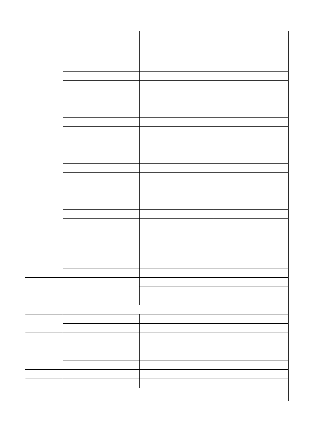
1. General Specifications
Norcent LT2722
LCD Panel
TV Function
Items
Screen Size 27” TFT LCD color Panel (CMO)
Aspect Ratio 16:9
Resolution 1280 x 720 (WXGA)
Active Display Area H x V 597.12mm x 335.88mm
Pixel Pitch 0.4665mm × 0.4665mm
Display colors 16.7 million
Contrast Ratio 600:1 (Typical)
Brightness 550 cd / m² (Typical)
Viewing Angle 170°(Horizontal) / 170°(Vertical)
Response Time 16.6 ms (Typical)
Lamp Lifetime 60,000 hr
Color Temperature Cool / Warm (For PC only)
TV Tuning System
Sound System
Color Systems
AV1
NTSC 181 Channel (PLL band) electronic adjustment system
MTS + SAP
NTSC
RCA x 1 Audio channel L/R x 1
Specification
Video Inputs
PC Input
Audio Output Audio Output: L / R
OSD language English, French and Spanish (default is English)
Power
Panel Tilt Forwards/Backwards/ Rotation -5° / +20°/ ±35°
AV2
Component
HDTV
Signal Input Analog: D-Sub 15 pin (detachable cable)
PnP compatibility DDC2B
Input frequency
Recommended Analog: 1024 x 768 (60Hz)
Input Audio Headphone Mini-jack for stereo (3.5 ø)
Power Supply AC 100V~240V, 50/60 Hz
Power Consumption <150 W
Operating Temp. +0°C ~ + 40°C
RCA x 1
S-Video x 1
YCbCr x 1 Audio channel L/R x 1
YPbPr x 1 Audio channel L/R x 1
Analog: FH: 31.5 KHz to 80 KHz
FV: 56 Hz to 75 Hz
Speaker (built-in): Two 5 watt speakers
Headphone Mini-jack jack stereo (3.5 ø)
Line Output (RCA L/R)
Audio channel L/R x 1
(Shared)
Environment
Dimension W x H x D (with stand) 898 x 500x285(mm)
Weight With Stand 13.4Kg
Accessories
Storage Temp. -10°C ~ + 60°C
Operating Humidity 10% ~ 85%
D-Sub Signal Cable, AC Power cord, 3.5mm Audio cable, Remote Controller, Battery (x2),
User’s manual
3
Page 6
y
r
r
2. Operations Instructions
y
y
p
t
grap
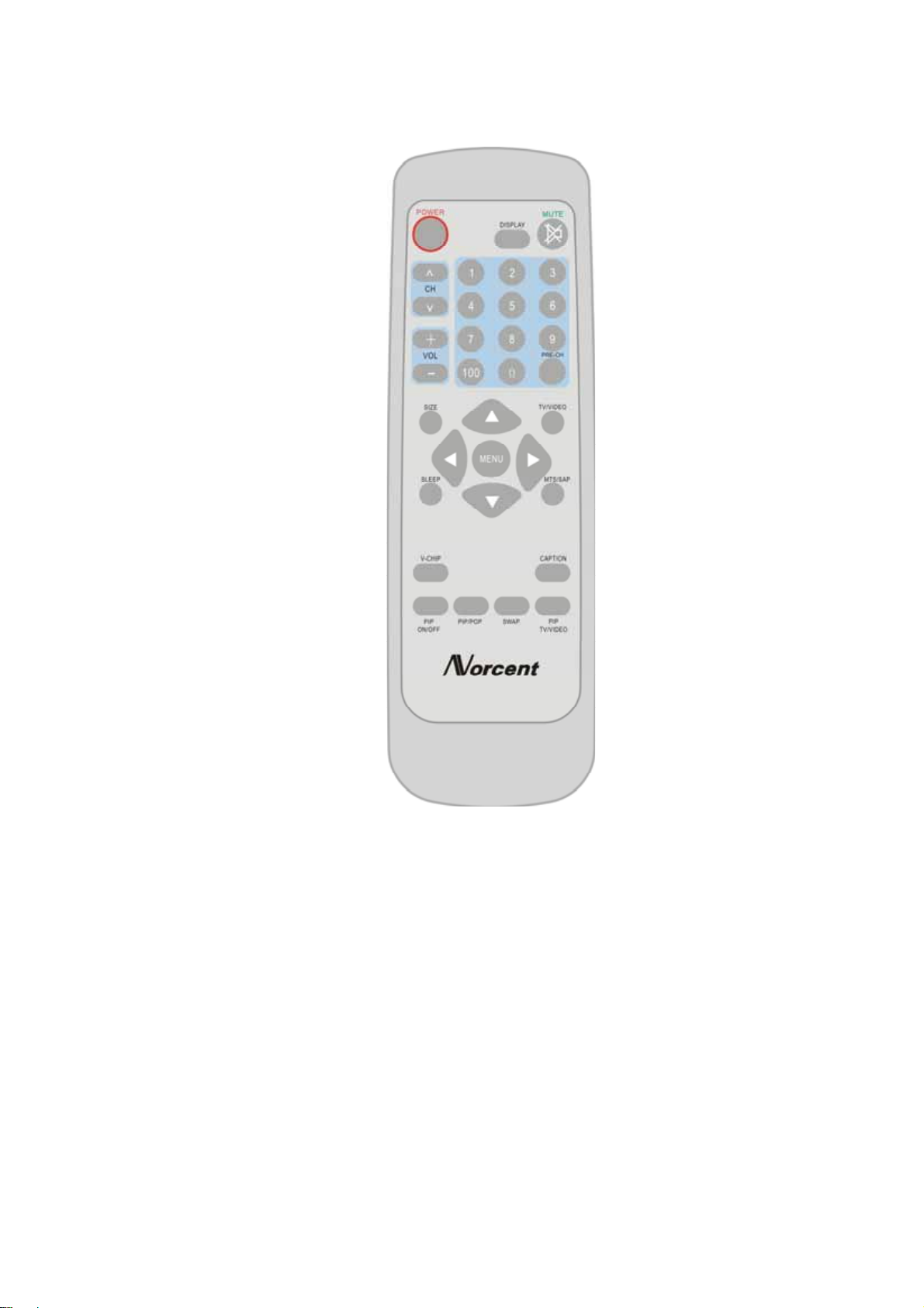
2.1 The Use Of Remote Control
POWER:
Press to turn on/off the TV. The TV
is never completely powered off
unless it is physically unplugged.
0~9/100 Digit buttons
To select a TV channel.
CH
Press ▲ or▼ to brows
through the TV channels
which are not erased. To
view a blocked channel,
use the digit buttons to
access the channel and
enter
our access code.
VOL
Press + or – to
adjust the volume.
SIZE
Display the graphic
in 16:9 or 4:3 mode
SLEEP
With this key you can set a
time period after which the
TV should switch itself to
standby. Press the ke
repeatedly to select the
number of minutes. The
counter runs from 0, 30, 60,
120 minutes. The time
begins to count down from
the number of minutes
selected after the display has
disappeared.
PIP
ON/OFF
Used to switch the PIP
function ON or OFF
PIP/POP
Press this button to
display PC input and
other input on the
screen at the same time
MENU, ▲, ▼, ◄, ►
These buttons are used to
display or adjust the various
functionalities.When the PIP
is ON but no menus are
available, use these ▲, ▼,
◄, ► to change the position
of the PIP.
V-CHIP
Use this button to define
the movies that this TV set
can receive
SWAP
Press to swap the two
screens when PIP o
POP is work
Norcent LT2722
MUTE
Temporarily interrupt
the sound or restore it.
DISPLAY
Press this button to
Display Channel
number on the right-top
MTS
Press this key to
activate Multichannel
Television Sound,
Stereo or Mono sound.
PRE-CH
To display the previousl
selected TV channel.
TV/VIDEO
Select your input source: press
TV/VIDEO and ▲, ▼, ◄, ► to
select TV ,S-VIDEO, AV1, AV2,
COMPONENT,VGA(PC) or
HDTV mode, according to
where you connected your
external source.
AV1/AV2 for a VCR connected
to the AV connectors of the
TV.
S-VIDEO for a S-Video VCR
connected to the S-VIDEO
connector of the TV.
COMPONENT and HDTV
input via Y,Cb,Cr / Y,Pb,Pr on
the DVD Player or set top
box.
VGA For PC mode
CAPTION
Press this button to turn
Closed Ca
PIP
TV/VIDEO
Select the signal source: If you
are in main picture or HDTV
mode, you can select audio1,
audio2, S-video, color contras
or TV signal. Otherwise, you
can only select computer
hics or HDTV.
tion on.
4
Page 7
Norcent LT2722
2.2 Front Panel Control Knobs
Power Key: Press to turn on or off the TV.
MENU Key: Press to show the OSD menu and exit OSD menu at the TV.
Down / Up Key: Press to perform select function and channel.
- / + Key: Press to confirm your function selection and adjustment.
Source Key: Press to select your input source.
2.3 OSD Operations
1. Press the MENU button to display or close the main menu.
2. Use the cursor up/down to select a menu item.
3. Use the cursor left/right to enter a submenu or enable/disable the function.
4. Press the MENU button to exit the menu.
5. Use the instruction bar display under the menu to assist in the operation of this equipment.
MAIN MENU
Press the MENU button into the main OSD (On Screen Display). Adjust item include PICTURE PARAMETERS,
PC PARAMETERS, AUDIO SETTINGS, PICTURE-IN-PICTURE, CHANNEL SETTINGS, PARENTAL
CONTROLS and GENERAL SETTINGS.
PICTURE PARAMETERS
BRIGHTNESS: Adjust the brightness of the image.
CONTRAST: Adjust the contrast of the image.
SATURATION: Adjust the depth of color of the image.
HUE: Adjust the red/green hue of the image.
COLOR TEMP: Adjust the color temperature to your preference: 5000°, 6500°, 9300°K or select USER R, USER G,
USER B to define your personal settings.
FLESHTONE: The flesh tone is automatically adjusted, rendering a more natural color.
SHARPNESS: Adjust the sharpness of the video image for display accordingly.
5
Page 8
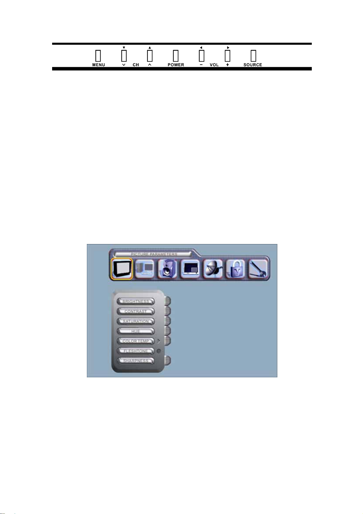
PC PARAMETERS
Norcent LT2722
AUTO CONFIG: Enable the automatic configuration of the optimum size of the graphic.
CLOCK: Adjust the time.
PHASE: Adjust the phase of the graphic.
POSITION: Adjust the position and angle of the graphic.
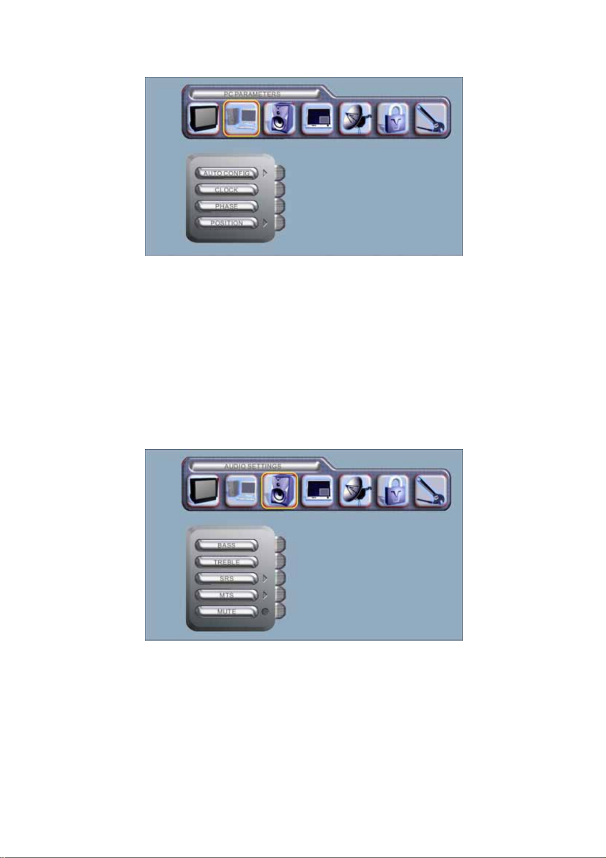
AUDIO SETTINGS
BASS: Adjust bass tone.
TREBLE: Adjust treble tone.
SRS: Switch SRS surround sound ON or OFF.
MTS: Select MONO, STEREO or SAP for bilingual setup.
MUTE: Temporarily mute the sound (can be done through remote control).
6
Page 9
Norcent LT2722
PICTURE-IN-PICTURE
PIP POSITION: The PIP can be placed in any position on the screen according to one’s wishes. If there is no
menu, use the ▲, ▼, ◄, ► buttons on the remote control to change the PIP position.
PIP SIZE: Can be used to switch the PIP off (OFF) or select the size (SMALL, MEDIUM, LARGE) of the PIP.
Can also be used to select one of two types (POP, PBP) of dual graphics.
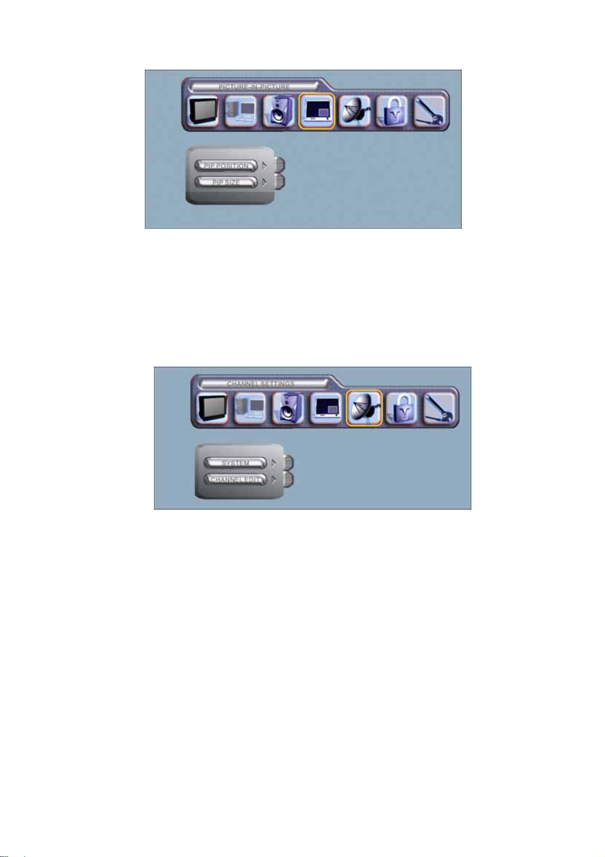
CHANNEL SETTINGS
SYSTEM: Used to choose between (ANTENNA) or (CABLE).
CHANNEL EDIT: The auto scan function searches and stores the signal of the TV station when the YES option is
selected. The ADD or DELETE function edits the TV station signal while the channel will be displayed if the
CURRENT CH function is selected.
7
Page 10
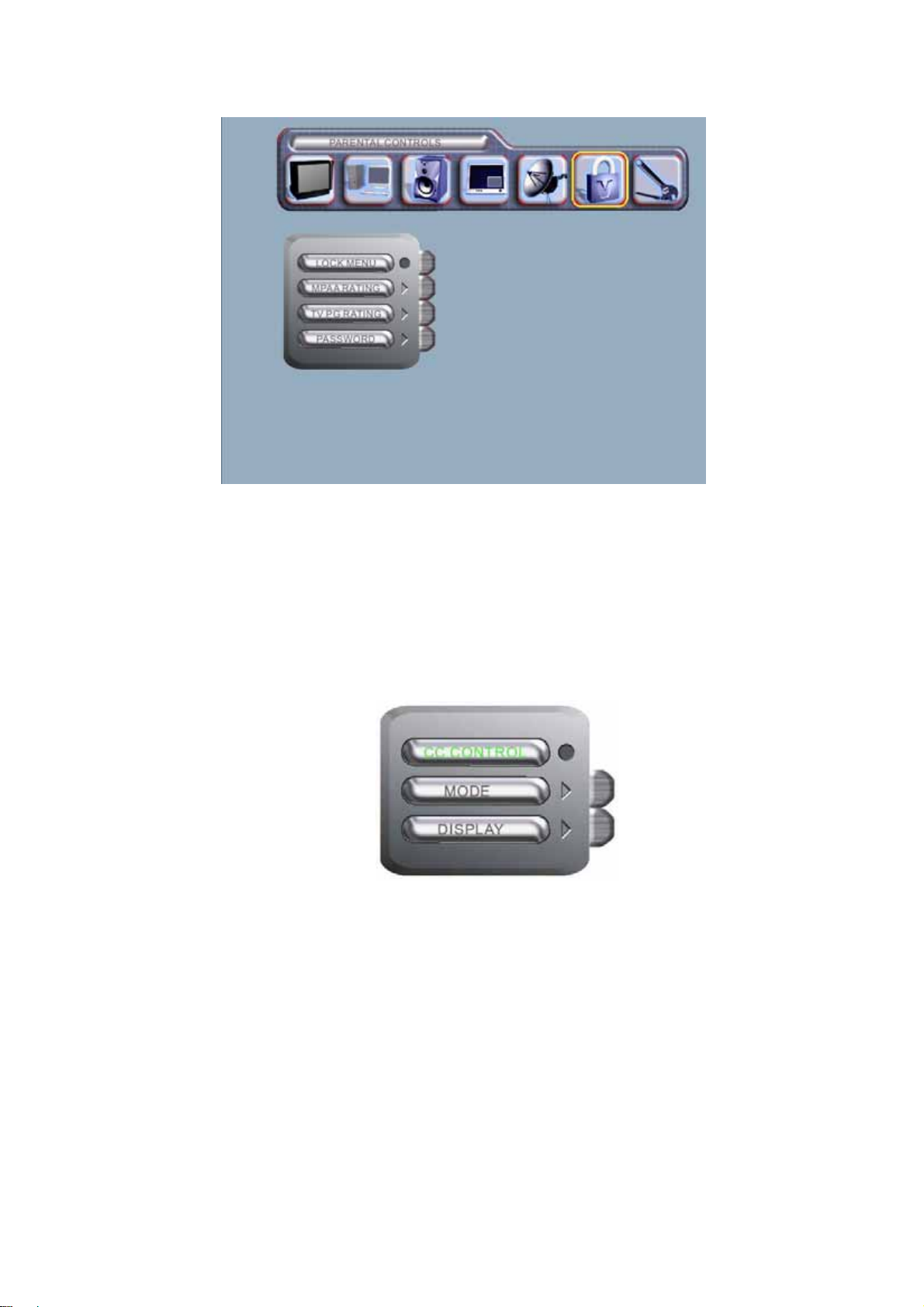
PARENTAL CONTROLS
Norcent LT2722
LOCK MENU: Switch the functionality to configure ratings on or off.
MPAA RATING: Configure MPAA ratings.
TV PG RATING: Configure TVPG ratings.
PASSWORD: Change the password (default is ‘1111”). Please follow the instructions on the screen. Once
changed, please remember your own password. If you have forgotten your password, please do the following:
“POWER (OFF) MENU V-CHIP MUTE” to revert to the default password of 1111.
CAPTION
Press the “CAPTION” button on the remote to initiate the functionality list as shown on the left.
CC CONTROL: Switch the subtitles function ON or OFF.
MODE: Select mode of subtitles.
DISPLAY: Select display of subtitles.
8
Page 11
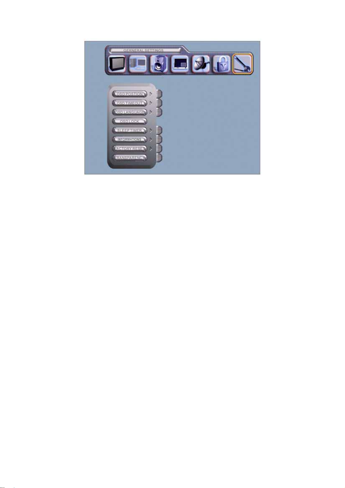
GENERAL SETTINGS
Norcent LT2722
OSD POSITION: Shift the position to one’s preference.
OSD TIMEOUT: Configure the time to be displayed on screen.
OSD LANGUAGE: Configure the language (English, French or Spanish) for the menu.
OSD LOCK: Lock the selected configurations to prevent them from being overwritten.
SLEEP TIMER: Configure the time for sleep mode.
INFORMATIONS : Display the resolution and H sync, V synch for the main graphic.。
FACTORY RESET: Select YES to revert to default configurations.
TRANSPARENCY: Adjust the brightness of the background.
9
Page 12

Norcent LT2722
2.4 Safety Notice
For Y our Safety
Before operating the TV please read this manual thoroughly. This manual should be retained for future reference。
FCC Class B Radio Frequency Interference St atement
WARNING: (FOR FCC CERTIFIED MODELS)
NOTE: This equipment has been tested and found to comply with the limits for a Class B digital device, pursuant to
Part 15 of the FCC Rules. These limits are designed to provide reasonable protection against harmful interference
in a residential installation. This equipment generates, radiate radio frequency energy, and if not installed and used
in accordance with the instructions, may cause harmful interference to radio communications. However, there is no
guarantee that interference will not occur in a particular installation. If this equipment does cause harmful
interference to radio or television reception, which can be determined by turning the equipment off and on, the user
is encouraged to try to correct the interference by one or more of the following measures:
1. Reorient or relocate the receiving antenna.
2. Increase the separation between the equipment and receiver.
3. Connect the equipment into an outlet on a circuit different from that to which the receiver is connected.
4. Consult the dealer or an experienced radio/TV technician for help.
NOTICE
1. The changes or modifications not expressly approved by the party responsible for compliance could void the
user's authority to operate the equipment.
2. Shielded interface cables and AC power cord, if any, must be used in order to comply with the emission limits.
WARNING:
To prevent fire or shock hazard, do not expose the TV to rain or moisture. Dangerously high voltages are present
inside the TV. Do not open the cabinet. Refer servicing to qualified personnel only.
SRS, SRS and
are registered trademarks of SRS Labs, Inc.
This product is designed using SRS technology with permission from SRS Labs, Inc.
SAFETY: Lamp Disposal
LAMP(S) INSIDE THIS PRODUCT CONTAIN MERCURY AND MUST BE RECYCLED OR DISPOSED OF
ACCORDING TO LOCAL, STATE OR FEDERAL LAWS. FOR MORE INFORMATION, CONTACT THE
ELECTRONIC
INDUSTRIES ALLIANCE AT WWW.EIAE.ORG.
10
Page 13

IMPORTANT SAFETY INSTRUCTIONS
Norcent LT2722
Read before operating equipment
1. Read these instructions.
2. Keep these instructions.
3. Heed all warnings.
4. Follow all instructions.
5. Do not use this apparatus near water.
6. Clean only with a dry cloth.
7. Do not block any of the ventilation openings. Install in accordance with the manufacturers instructions.
8. Do not install near any heat sources such as radiators, heat registers, stoves, or other apparatus (including
amplifiers) that produce heat.
9. Do not defeat the safety purpose of the polarized or grounding type plug. A polarized plug has two blades with
one wider than the other. A grounding type plug has two blades and third grounding prong. The wide blade or
third prong is provided for your safety. When the provided plug does not fit into your outlet, consult an electrician
for replacement of the obsolete outlet.
10. Protect the power cord from being walked on or pinched particularly at plugs, convenience receptacles, and the
point where they exit from the apparatus.
11. Only use attachments/accessories specified by the manufacturer.
12. Use only with a cart, stand, tripod, bracket, or table specified by the manufacturer, or sold with the apparatus.
When a cart is used, use caution when moving the cart/apparatus combination to avoid injury from tip-over.
13. The TV should be operated only from the type of power source indicated on the label. If you are not sure of the
type of power supplied to your home, consult your dealer or local power company.
14. Unplug this apparatus during lightning storms or when unused for long periods of time.
15. Refer all servicing to qualified service personnel. Servicing is required when the apparatus has been damaged
in any way, such as power-supply cord or plug is damaged, liquid has been spilled or objects have fallen into
apparatus, the apparatus has been exposed to rain or moisture, does not operate normally, or has been
dropped.
16. This product may contain lead or mercury. Disposal of these materials may be regulated due to environmental
considerations. For disposal or recycling information, please contact your local authorities or the Electronic
Industries Alliance: www.eiae.org
17. Damage Requiring Service – The appliance should be serviced by qualified service personnel when:
A. The power supply cord or the plug has been damaged; or
B. Objects have fallen, or liquid has been spilled into the appliance; or
C. The appliance has been exposed to rain; or
D. The appliance does not appear to operate normally or exhibits a marked change in performance; or
E. The appliance has been dropped, or the enclosure is damaged.
Tilt/Stability – All televisions must comply with recommended international global safety standards for tilt and
stability properties of its cabinets design.
Do not compromise these design standards by applying excessive pull force to the front, or top, of the cabinet,
which could ultimately overturn the product.
Also, do not endanger yourself, or children, by placing electronic equipment/toys on the top of the cabinet. Such
11
Page 14
Norcent LT2722
items could unsuspectingly fall from the top of the set and cause product damage and/or personal injury.
Power Lines – An outdoor antenna should be located away from power lines.
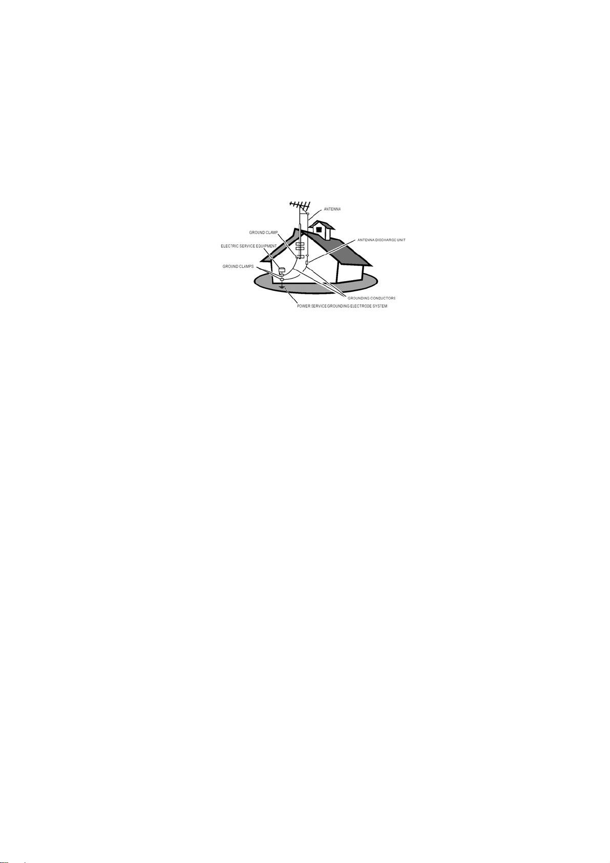
Outdoor Antenna Grounding – If an outside antenna is connected to the receiver, be sure the antenna system is
grounded so as to provide some protection against voltage surges and built up static charges.
Section 810 of the National Electric Code, ANSI/NFPA No. 70-1984, provides information with respect to proper
grounding of the mats and supporting structure grounding of the lead-in wire to an antenna-discharge unit, size of
grounding connectors, location of antenna-discharge unit, connection to grounding electrodes and requirements for
the grounding electrode. See Figure below.
EXAMPLE OF ANTENNA GROUNDING AS PER NATIONAL ELECTRICAL CODE
Note to the CATV system installer: This reminder is provided to call the CATV system installer ’s attention to Article
820-40 of the NEC that provides guidelines for proper grounding and, in particular, specifies that the cable ground
shall be connected to the grounding system of the building, as close to the point of cable entry as practical.
Objects and Liquid Entry – Care should be taken so that objects do not fall and liquids are not spilled into the
enclosure through openings.
12
Page 15
Norcent LT2722
3. Input Specification
3.1 Input Signal connector
This procedure gives you instructions for installing and using the LCD TV display.
Lay the display on the desired operation and plug the power cord into a convenient AC outlet. Three-wire power
cord must be shielded and is provided as a safety precaution as it connect s the chassi s and ca binet to the electri ca l
conduct ground. If the AC outlet in your location does not have provisions for the grounded type plug, the installer
should attach the proper adapter to ensure a safe ground potential.
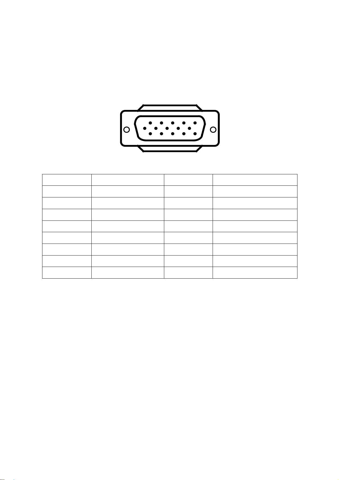
Connect the 15-pin D-SUB color display shielded signal cable to your sign al system device a nd lock both screws on
the connector to ensure firm grounding. The connector information is as follow:
1
6
11 15
5
10
15 - Pin Color Display Signal Cable
Pin No. Description Pin No. Description
1. Red Video 9. No Pin
2. Green Video 10. Sync Ground
3. Blue Video 11. Not Used
4. Not Used 12. Serial Data for DDC
5. Ground 13. Horiz. Sync
6. Ground-R 14. Vert. Sync
7. Ground-G 15. Serial Clock for DDC
8. Ground-B
Apply power to the display by turning the power switch to the "ON" position and allow about te n secon ds for Pane l
warm-up. The Power-On indicator lights "GREEN" when the display is on.
With proper signals feed to the display, a pattern or data should appear on the screen, adjust the brightness and
contrast to the most pleasing display, or press auto-adjust to get the best picture-quality.
This TV (with PC function) has power saving function following the VESA DPMS. Be sure to connect the signal
cable to the PC.
If your TV requires service, it must be returned with the power cord.
13
Page 16

3.2 Factory Preset Display Modes:
Horizontal Vertical
Resolution
720x400 31.5 N 70.1 P
640x480 31.5 N 59.9 N
640x480 37.9 N 72.8 N
640x480 37.5 N 75 N
800x600 37.9 P 60.3 P
800x600 48.1 P 72.2 P
800x600 46.9 P 75 P
1024x768 48.3 N 60 N
1280x1024 80 P 75 P
Frequency
Nominal
(KHz)
VGA MODES
Sync
Polarity
Nominal
Freq.
(Hz)
Norcent LT2722
Sync
Polarity
14
Page 17
Norcent LT2722
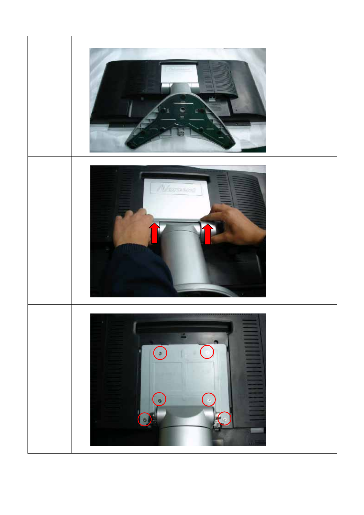
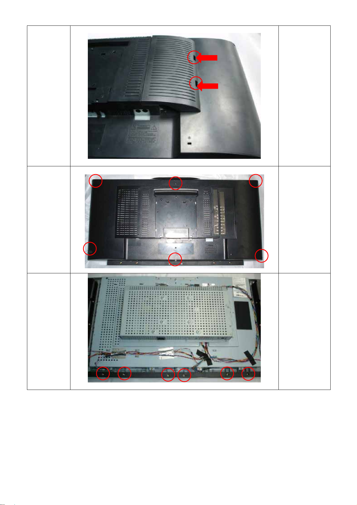
4. Mechanical Instructions
Step Figure Description
Lay the LCD-TV
Preparation
on a flat, soft and
clean surface.
Remove
hinge
cover
Remove
base
Remove the
hinge cover as
the arrowheads.
Remove the six
screws
15
Page 18
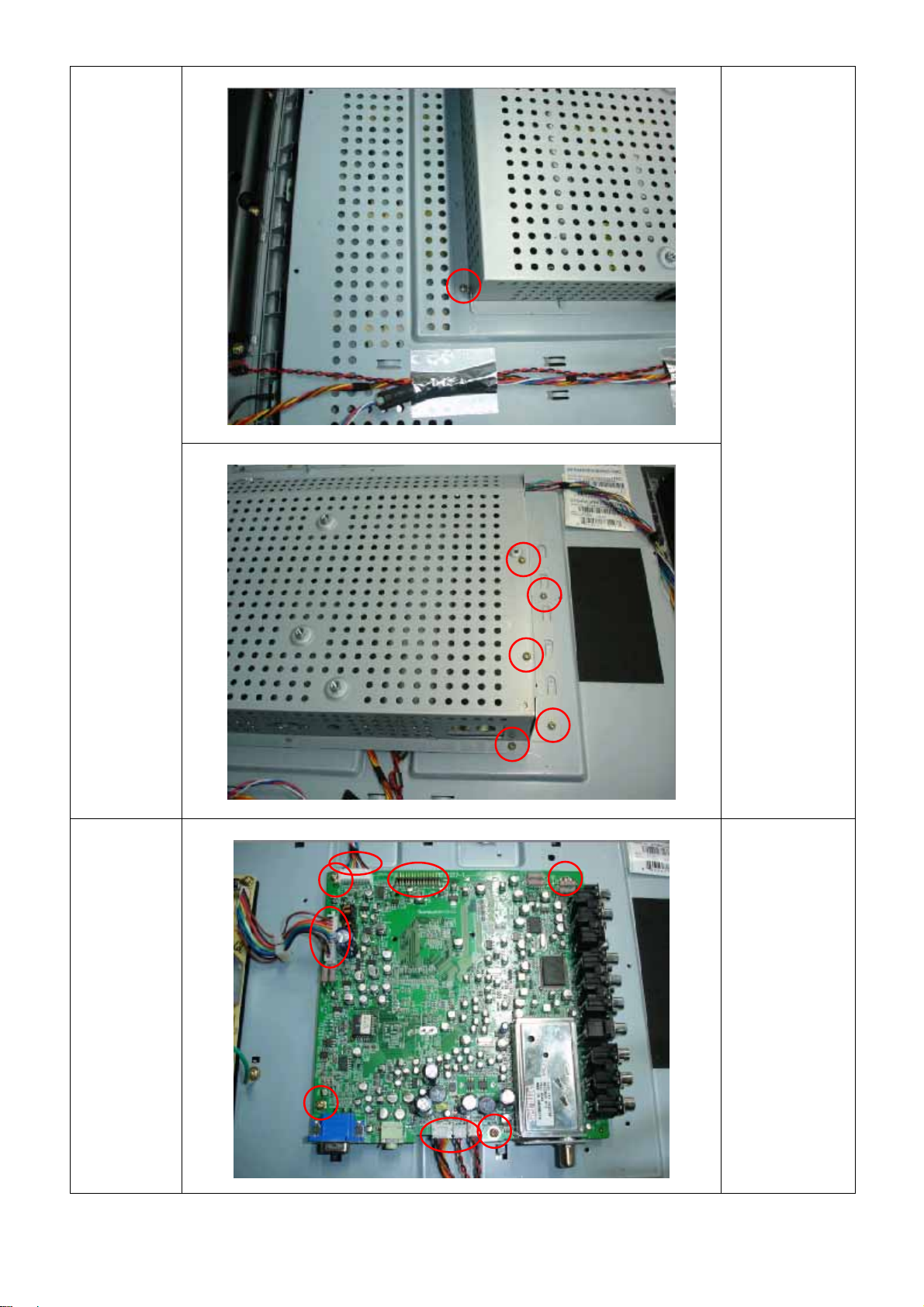
Norcent LT2722
Remove
cover cable
Remove
back cover
Push the clip as
the arrowheads
Remove the six
screws
Remove
cover chin
Remove the six
16
screws
Page 19
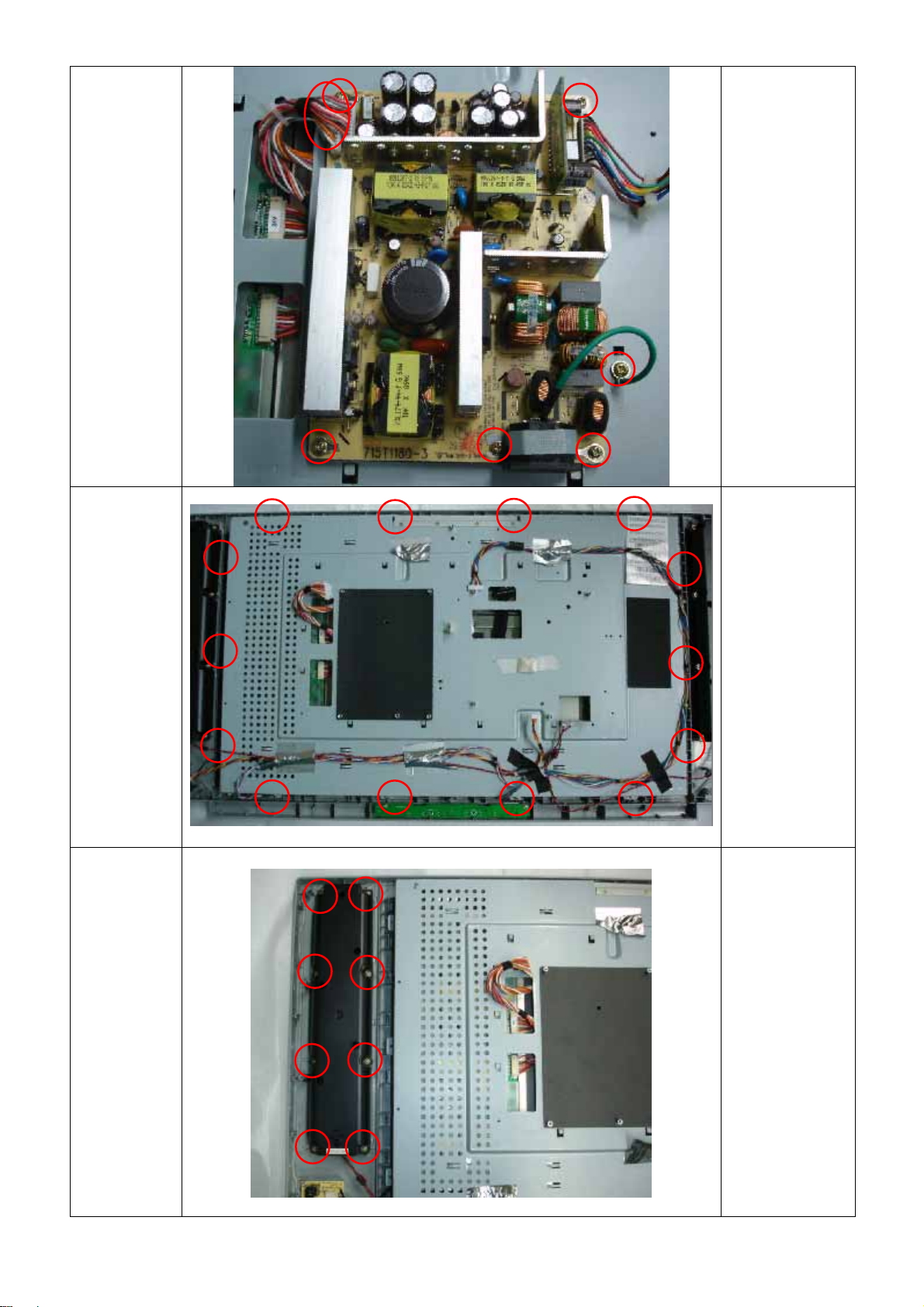
Norcent LT2722
Remove
shield
Remove the total
six screws
Remove
main board
17
Remove the four
scres and
disconnect he
wire harnesses
Page 20
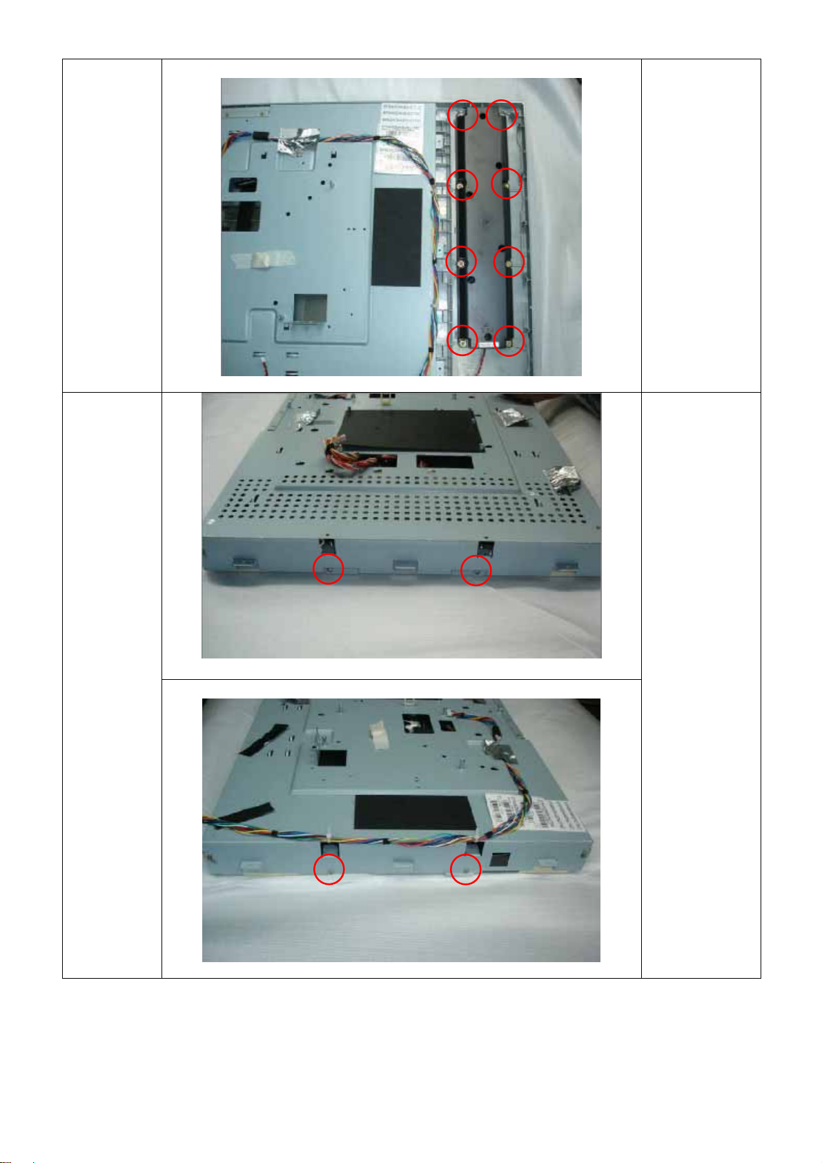
Norcent LT2722
Remove
power
board
Remove
main frame
Remove the six
screws and
disconnect the
wire harness
Remove the
fourteen screws
Remove
speakers
and bezel
Remove the
sixteen
screws(the left
and right two
speakers)
18
Page 21
Norcent LT2722
Remove
panel
Remove the four
screws
19
Page 22
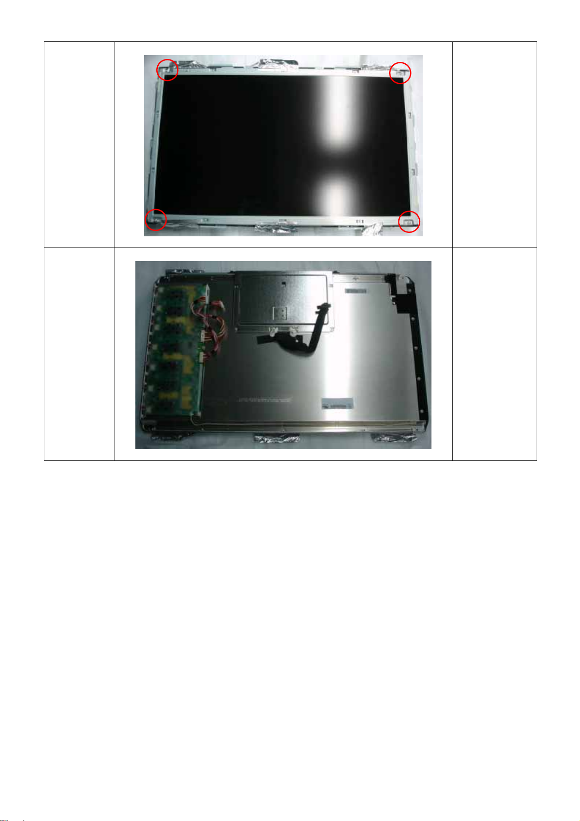
Norcent LT2722
The end
Remove the four
screws
20
Page 23
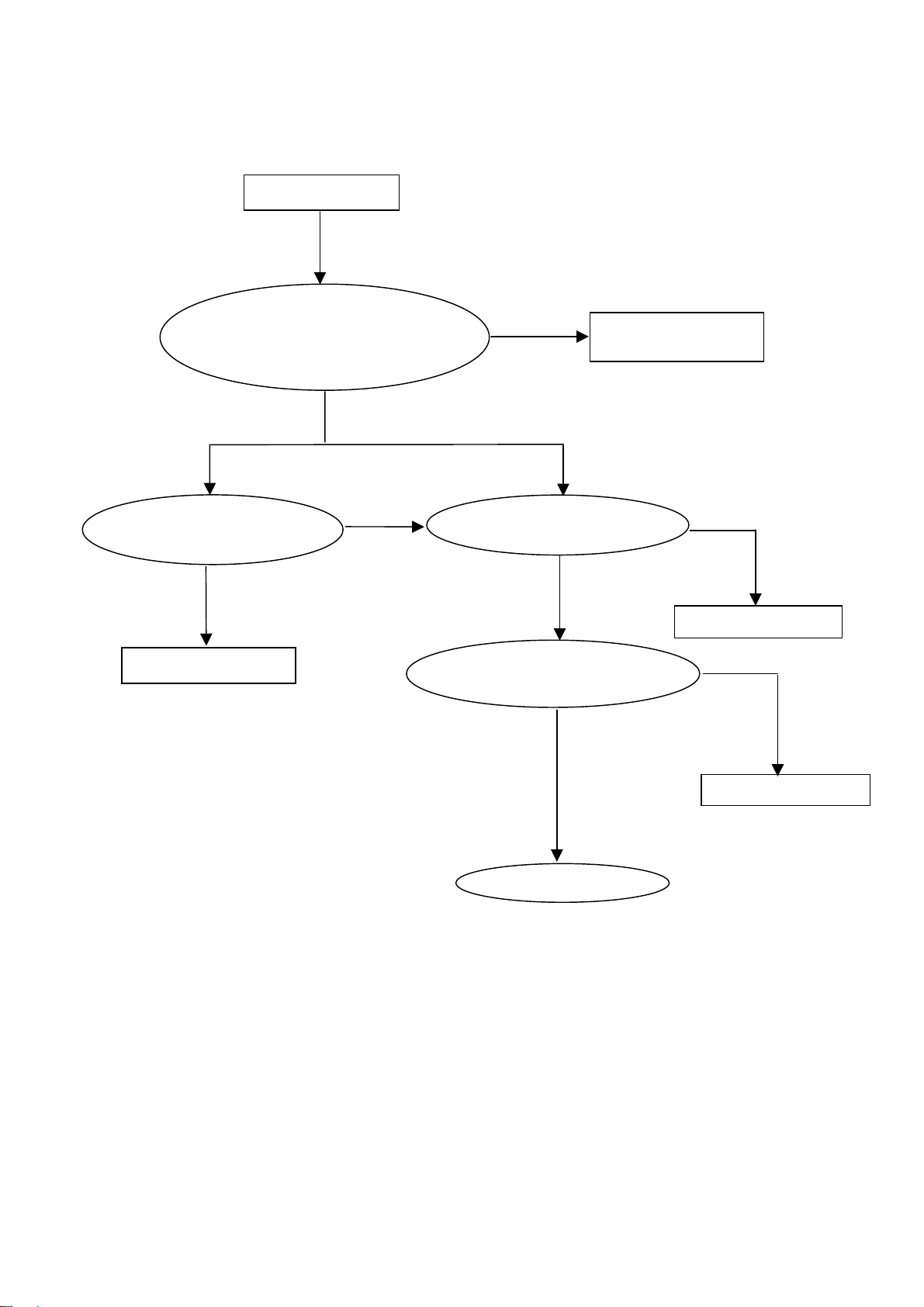
5. Repair Flow Chart
(
)
g
Panel Control Circuit
Check CN605 pin 19-22
is 5V and signal on pin
3,4,6,7,9,10,12,13,15,16
NO 5V
Check Q401, Q400
relative circuit
NG
Replace Q401, Q400
No Display
OK
NO Si
Check U403 crystal
14.318MHZ
X400
OK
Check power supply for
1.8V, 2.5V, and 3.3V
OK
Replace U403
Norcent LT2722
Replace panel or
FPC cable to panel
nal
NG
Replace X400
Check relative circuit
21
Page 24
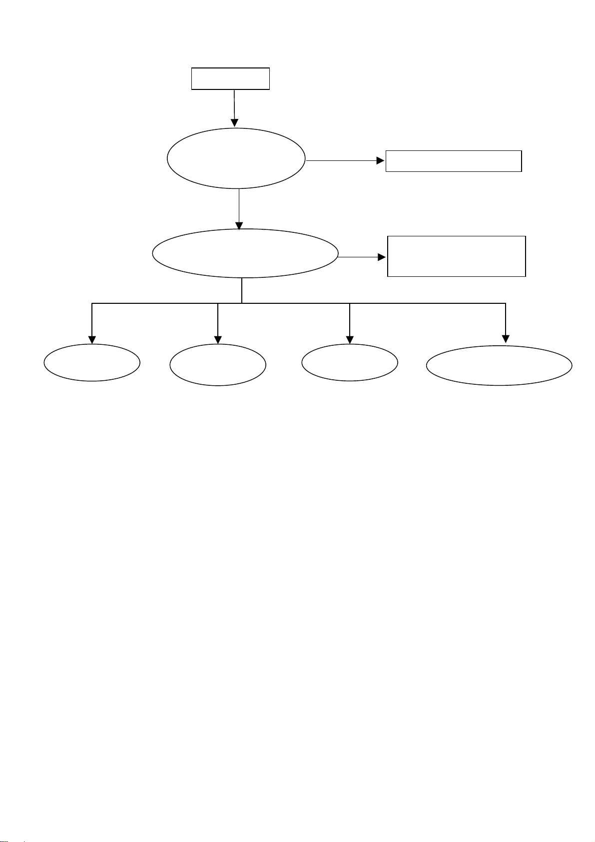
Main Board Power Circuit
(
)
No Power
OK
Check CN606
Pin 3, 4(12V),
Pin 5, 6 (5V)
NG
OK
Check U701 input (5V),
U706 input (12V)
NG
OK
U704 Pin2
U700 Pin2
(1.8V)
U705 Pin2
Norcent LT2722
Check Power Board circuit
Check Q701, Q702 and
PWR_ON control relative
circuit
U701/U702/U703/U
704 Pin2
2.5V
22
Page 25

Remote Control Block
p
G
Remote Control can’t work
Check IR Board J1 Pin 1,4(5V)
and voltage at Pin 3 will change
when received signal
Check Main board 5V power
relative circuit and signal on
LP602
Check Power relative
circuit
Key Board Control Block
NG
Press key no function
Check CN600 Pin6, 7, 8
voltage will change when key
ressed
be
N
Check line between keyboard
and main board or U403
NG
Check U403 and relative circuit
OK
OK
Norcent LT2722
Replace D600 or IR board
Replace line between Main
board and IR Board or
replace U403
OK
Replace keyboard
23
Page 26

PC Control Block
r
(HS,
)
Norcent LT2722
No Display
OK
Check U403 output
relative circuit and panel
control circuit
OK
Check U403 crystal
X400 (14.318MHZ)
OK
Check power supply fo
1.8V, 2.5V, and 3.3V
OK
NG
NG
NG
Check CN605, FPC
cable and panel
Replace X400
Check relative circuit
Check CN300 Pin1, 2,
3 (R, G, B) and Pin13,
VS
14
Replace U403
OK
NG
Check relative circuit
24
Page 27

Audio Control Block
6
pply
p
g
O
Norcent LT2722
No Sound
Check CN604, CN609
and L613, L614, L616,
17
L
NG
Check U603, U604 output
relative circuit and power
24V
su
NG
Check CN602 Pin3-4 and
Pin1-2 are short when no
hone plu
ear-
NG
Check U200/U105 output
relative circuit
K
OK
Replace speaker
Check earphone board
NG NG
Check TUNER
Pin11 to U105
relative circuit
Check U600, U601 output
to U105 relative circuit
Check U600, U601
input signals
NG
25
Page 28

Norcent LT2722
6. White-Balance, Luminance adjustment
Approximately 30 minutes should be allowed for warm up before proceeding white balance
adjustment.
Before started adjust white balance, please setting the Chroma-7120 MEM. Channel 1 to 9300 color, MEM.
Channel 2 to 6500 color, and MEM. Channel 3 to 9300 color, (9300 parameter is x =283, y = 297, Y =
380cd/m2 (PC Mode); 6500 parameter is x = 313, y = 329, Y = 380cd/m
y = 297, Y> 450cd/cm2 (TV Mode))
Color Temp. 9300(PC Mode) 6500(PC Mode) 9300(TV Mode)
X 0.283 0.313 0.283
Y 0.297 0.329 0.297
Y 380 380 >450
How to setting MEM.channel you can reference to Chroma-7120 user guide or simple use “ SC” key and
“ NEXT” key to modify x,y,Y value and use “ID” key to modify the TEXT description
Following is the procedure to do white-balance adjust
Press Number key 100 9 9 9 will into the factory mode, and OSD will be shown in the screen, then
select MORE function will into Bias and Gain adjustment.
1. ADC Adjustment:
AL Auto level adjust for PC mode.
ALY Auto level adjust for YUV mode.
RG, GG, BG R, G, B Gain adjust.
RB, GB, BB R, G, B Bias adjust.
2. SCALER Adjustment:
CO, BR Contrast and Brightness adjust.
RG, GG, BG R, G, B Gain adjust.
RB, GB, BB R, G, B Bias adjust.
S9, S6, ST, SH Save 9300, 6500, TV/AV /S-Video /480i, Component 480P color temperature.
R9, R6, RT, RH Recall 9300, 6500, TV/AV /S-Video /480i, Component 480P color temperature.
CC Set Close Caption ON/OFF.
VC Set V Chip ON/OFF.
WH Set Wireless Headphone ON/OFF.
PP Set PIP ON/OFF.
BI Setup Burn-in mode ON / OFF.
ISP Set ISP ON/OFF.
SR PP Set SRS ON/OFF.
EX Exit MORE function to factory mode menu.
I. Before adjustment:
1. Press Number key 100 9 9 1 into Engineer Mode.
2. Press menu key repeat to “ADC “page, then select “EPinit” and press “right” key to initial EEPROM.
3. Press Number key 100 9 9 9 into the Factory Mode.
II. Gain adjustment:
A. Adjust 9300 color-temperature:
1. Switch the chroma-7120 to RGB-mode (with press “MODE” button)
2. Switch the MEM. Channel to Channel 01 (with up or down arrow on Chroma-7120)
3. The LCD-indicator on chroma-7120 will show x = 283, y=297, Y>380.
4. Change Source input to PC.
5. Select AL and press “right” arrow to do the auto-level.
6. Adjust the GG up to G value at chroma-7120 is 100.
7. Adjust the BG and RG till the value of R and B value on Chroma-7120 are 100±5.
8. Repeat the item 4 and 5 to make the R, G, B value are the same.
9. Select cursor to “S9” and press “right” arrow to save the value.
2
(PC Mode); 9300 parameter is x =283,
26
Page 29

Norcent LT2722
B. Adjust 6500 color-temperature:
1. Switch the chroma-7120 to RGB-mode (with press “MODE” button)
2. Switch the MEM. Channel to Channel 02 (with up or down arrow on Chroma-7120)
3. The LCD-indicator on chroma-7120 will show x = 313, y=329, Y>380.
4. Change source input to PC.
5. Select AL and press “right” arrow to do the auto-level.
6. Adjust the GG up to G value at chroma-7120 is 100.
7. Adjust the BG and RG till the value of R and B value on Chroma-7120 are 100±5.
8. Repeat the item 4 and 5 to make the R, G, B value are the same.
9. Select cursor to “S6” and press “right” arrow to save the value.
C. Adjust Video color-temperature:
1. Switch the chroma-7120 to RGB-mode (with press “MODE” button)
2. Switch the MEM. Channel to Channel 03 (with up or down arrow on Chroma-7120)
3. The LCD-indicator on chroma-7120 will show x = 283, y=297, Y>450.
4. Change source input to AV1.
5. Adjust the GG up to G value at chroma-7120 not going up; set the G value is max.
6. Adjust the BG and RG till the value of R and B value on Chroma-7120 same as G value.
7. Repeat the item 4 and 5 to make the R, G, B value the same.
8. Select cursor to “ST” and press “right” arrow to save the value.
Turn the POWER-button off to on to quit from factory mode.
Remark: 1. Auto Level of PC should be adjusted with TIMG 127, PATN 42 or 16 GRAYS screen.
2. It should be under white picture while adjusting the color temperature of all display modes.
27
Page 30

7. BOM List
Location
ADPF24180A2 A/D+D/D POWER 1 PCS
CBPFF84KMGNCT MAIN BOARD 1 PCS
11T6048 1 CLAMP-S 1 PCS
15T5908 2 BRACKET 1 PCS
15T6096 2 11 MAIN FRAME 1 PCS
15V6161 1 BKT CONNECTOR 1 PCS
26T 800504 5 BARCODE 1 PCS
34V1305CGN 3L COVER HINGE 1 PCS
34V1306 GM L COVER CABLE 1 PCS
36V 600 3 Girdding Cloth FOR AUSI 1.02 PCS
40T 270815 4B ID LABEL 1 PCS
40T 58160811A GREEN LEBEL 1 PCS
40T 58162435A LABEL 1 PCS
40T 583 16 TV ICON LABEL 1 PCS
40T 583 17 TV ICON LABEL 1 PCS
41T2701815 3A MANUAL 1 PCS
41T780081523A QSG 1 PCS
41T780081524A WARRANTY CARD 1 PCS
44T2701 1 EPS FOR 27" 1 PCS
44T2701 3 EPS 1 PCS
44T2701815 5A CARTON 1 PCS
44T3231 15 EVA WASHER 1 PCS
44TZ002200 1 PIZZA BOX 1 PCS
45T 76 28 RN PE BAG FOR MANUAL 1 PCS
45T 88606 3 PE BAG FOR BASE 1 PCS
45T 88609 9 DE BAG 1 PCS
45T 88609 15 EPE COVER FOR BASE 1 PCS
45T 88626 5 PE BAG FOR MOUITOR 1 PCS
50T 500 1 CABLE TIE 2 PCS
52T 1185 MIDDLE TAPE FOR CARTON 270 CM
52T 1186 SMALL TAPE 10 CM
52T 1211 A ADHESIVE TYPE 4 PCS
52T6020 9 PROTECT FILM 1 PCS
85V6085 2 SHIELD 1 PCS
89T 173 56 8 AUDIO CABLE 1 PCS
E089B 89T1738GAA D1 SIGNAL CABLE 1 PCS
89T402A18N IS POWER CORD 1 PCS
92TB1JX1A31GF BATTERY 2 PCS
95T8014 10 11 WIRE HARNESS 1 PCS
95T8014 10506 WIRE HARNESS 1 PCS
95T8014 12 13 WIRE HARNESS 1 PCS
95T8018 30549 WIRE HARNESS 1 PCS
98TR7SWANENCF Remote Control 1 PCS
M1V 140 10120 SCREW M4X10 6 PCS
M1V 330 3128 SCREW 4 PCS
M1V 330 4128 SCREW M3X4 2 PCS
M1V 330 4128 SCREW M3X4 4 PCS
M1V 330 6128 SCREW 1 PCS
M1V 330 6128 SCREW 1 PCS
M1V 340 14120 SCREW 4 PCS
M1V1140 4128 SCREW 4X6 1 PCS
M1V1730 6128 SCREW 5 PCS
M1V1730 6128 SCREW 4 PCS
Norcent LT2722
Part No. for TPV Description Quantity Unit
28
Page 31

Norcent LT2722
Q1V 330 12120 SCREW 3X12mm 5 PCS
Q1V 930 6128 SCREW (T3X6) 5 PCS
Q1V1030 12128 SCREW 14 PCS
705LF84FB34006 TV BACK COVER ASS'Y 1 PCS
E750L 750VVMH0 W12NC CMO 27" NORCENT CONSIGN 1 PCS
AD24180A2SMT LCD ADAPTER ASS'Y FOR S 1 PCS
DCPF1205A3 DC TO DC BOARD 1 PCS
CN951 33T3802 10 PLUG 1 PCS
CN952 33T3802 12 WAFER PH-12 1 PCS
40T 45762420A S/N LABEL 1 PCS
IC922 56T 139 3A PC123Y22FZOF 1 PCS
IC924 56T 139 3A PC123Y22FZOF 1 PCS
IC925 56T 139 3A PC123Y22FZOF 1 PCS
IC942 56T 139 3A PC123Y22FZOF 1 PCS
R950 61T 20K398GB1 CEMENTR 0.39 OHM +-10% 1 PCS
R921 61T152M10458G6267 100K OHM 5% 2W 1 PCS
R905 61T153M27858G6267 0.27 OHM 5% 3W 1 PCS
R919 61T153M27858G6267 0.27 OHM 5% 3W 1 PCS
R945 61T153M47358G6267 47K OHM 5% 3W 1 PCS
C901 63T 10722410S 0.22UF 275VAC X2 1 PCS
C905 63T213J105GFA MPF CAP 1 PCS
C926 64T400K473 57 MPF CAP 1 PCS
C922 65T 1K222 2A6213 0.0022UF/1KV 1 PCS
C942 65T 1K222 2A6213 0.0022UF/1KV 1 PCS
C921 65T 1M103 3T6921 0.01uf 20% 1000V Y5V 1 PCS
C903 65T306M1022BM Y1.CAP.001UF 250VAC MUR 1 PCS
C904 65T306M1022BM Y1.CAP.001UF 250VAC MUR 1 PCS
C915 65T306M1022BM Y1.CAP.001UF 250VAC MUR 1 PCS
C970 65T306M2222BP Y1.CAP.0022UF 250V AC 1 PCS
C907 67T 40K18116K 105C EC SHAP-IN 1 PCS
C930 67T215L102 6N KY35VB1000M-L 5*25MM 1 PCS
C948 67T215L102 6N KY35VB1000M-L 5*25MM 1 PCS
C949 67T215L102 6N KY35VB1000M-L 5*25MM 1 PCS
C950 67T215L102 6N KY35VB1000M-L 5*25MM 1 PCS
C951 67T215L102 6N KY35VB1000M-L 5*25MM 1 PCS
C932 67T215L1024NL KY25VB1000M-L 10*25MM 1 PCS
C933 67T215L1024NL KY25VB1000M-L 10*25MM 1 PCS
C934 67T215L221 4R LOWE.S.R 220UFM 25V 1 PCS
C931 67T215L221 6N KY35VB220M-L 8*15MM 1 PCS
C955 67T215L471 6N KY35VB470M-L 10*20MM 1 PCS
L906 73L 174 44 TG CHOKE COIL 1 PCS
L953 73L 174 46LSG FILTER 1 PCS
L952 73L 174 47LSG LINE FILTER 1 PCS
L903 73L 174 48 LG LINE FILTER 1 PCS
L904 73L 174 49LSG LINE FILTER 1 PCS
L905 73L 174 52LSG CHOKE COIL 1 PCS
L901 73L 253156 TH CHOKE COIL 1 PCS
L902 73L 253156 TH CHOKE COIL 1 PCS
L922 73T 253155 L CHOKE 1 PCS
L923 73T 253155 L CHOKE 1 PCS
T951 80LL26T 2 TG X'FMR 1 PCS
T921 80LL26T 3 TG XFMR 1 PCS
D922 93T1020 752T UF4003PT 1 PCS
D943 93T1020 752T UF4003PT 1 PCS
D920 93T1100 1052T BA159GPT 1 PCS
D921 93T1100 1052T BA159GPT 1 PCS
D941 93T1100 1052T BA159GPT 1 PCS
29
Page 32

Norcent LT2722
D942 93T1100 1052T BA159GPT 1 PCS
RJ905 95T 90 26 WIRE HARNESS 1 PCS
CN921 95T8013 12 8 WIRE HARNESS 1 PCS
705L F94 57 01 Q901/Q941/D902 ASS'Y 1 PCS
705L F94 57 02 Q942/Q943/D927/D928 ASS 1 PCS
705L F94 56 01 IC981 ASS'Y 1 PCS
705L F94 87 01 CN901 ASS'Y 1 PCS
705L F94 93 01 BD901 ASS'Y 1 PCS
AD24180A2AI LCD ADAPTER ASS'Y FOR A 1 PCS
IC941 56T 379 38 L6565D SO-8 1 PCS
IC901 56V 538 8 TDA4863-2G SO-8 1 PCS
Q922 57T 417 4 CHIP PMBS3904 BY PHILIP 1 PCS
Q924 57T 760 5 DTC144WKA BY FOHM SMT 1 PCS
R922 61V0805000 CHIP 0OHM 1/10W 1 PCS
R944 61V0805000 CHIP 0OHM 1/10W 1 PCS
R947 61V0805000 CHIP 0OHM 1/10W 1 PCS
R954 61V0805100 CHIP 10OHM 1/10W 1 PCS
R955 61V0805100 CHIP 10OHM 1/10W 1 PCS
R920 61V0805100 2F CHIP 10K OHM 1/8W 1% 1 PCS
R940 61V0805100 2F CHIP 10K OHM 1/8W 1% 1 PCS
R931 61V0805102 CHIPR 1K OHM +-5% 1/8W 1 PCS
R934 61V0805102 CHIPR 1K OHM +-5% 1/8W 1 PCS
R909 61V0805103 CHIP 10K OHM 1/10W 1 PCS
R910 61V0805103 CHIP 10K OHM 1/10W 1 PCS
R965 61V0805103 CHIP 10K OHM 1/10W 1 PCS
R964 61V0805104 CHIPR 100K OHM+-5% 1/8W 1 PCS
R959 61V0805115 2F CHIP 11.5K OHM 1/10W 1% 1 PCS
R960 61V0805133 CHIPR 13KOHM +-5% 1/8W 1 PCS
R961 61V0805152 CHIPR 1.5K OHM +-5% 1/8 1 PCS
R914 61V0805191 2F 19.1K OHM 1/8W 1% 1 PCS
R957 61V0805200 9F CHIP 20 OHM 1/10W 1% 1 PCS
R958 61V0805202 CHIP 2KOHM 1/8W 1 PCS
R936 61V0805220 CHIP 22 OHM 5% 0805 1/8 1 PCS
R967 61V0805222 CHIP 2.2KOHM 5% 0805 1/ 1 PCS
R951 61V0805242 CHIP 2.4KOHM 1% 1/8W 1 PCS
R949 61V0805273 CHIP 27KOHM 5% 0805 1/8 1 PCS
R930 61V0805280 3F CHIP 280K OHM 1/10W 1 PCS
R948 61V0805330 CHIP 33 OHM 5% 1/10W 1 PCS
R904 61V0805470 CHIP 47 OHM 1/10W 1 PCS
R933 61V0805471 CHIPR 470 OHM+-5% 1/8W 1 PCS
R935 61V0805472 CHIRP 4.7K OHM +-5% 1/8 1 PCS
R932 61V0805510 2F CHIP 51K OHM 1/10W 1 PCS
R953 61V0805563 CHIP 56K OHM 1/8W 1 PCS
R952 61V0805682 CHIP 6.8KOHM 5% 0805 1/ 1 PCS
R903 61V0805683 CHIPR 68K OHM+-5% 1/8W 1 PCS
R925 61V0805689 CHIP 6.8OHM 5% 1/8W 1 PCS
R908 61V1206000 CHIP 0 OHM 1/8W 1 PCS
RJ901 61V1206000 CHIP 0 OHM 1/8W 1 PCS
RJ903 61V1206000 CHIP 0 OHM 1/8W 1 PCS
R983 61V1206100 3F CHIP 100K OHM +-1% 1/4W 1 PCS
R923 61V1206100 4F 1M OHM 1/4W 1% 1 PCS
R924 61V1206100 4F 1M OHM 1/4W 1% 1 PCS
R968 61V1206101 CHIP 100 OHM 5% 1/4W 1 PCS
R962 61V1206102 CHIP 1K OHM 5% 1/4W 1 PCS
R926 61V1206205 CHIP 2M OHM 5% 1/4W 1 PCS
R927 61V1206205 CHIP 2M OHM 5% 1/4W 1 PCS
R929 61V1206330 CHIP 33 OHM 5% 1/4W 1 PCS
30
Page 33

Norcent LT2722
R946 61V1206330 CHIP 33 OHM 5% 1/4W 1 PCS
R974 61V1206330 CHIP 33 OHM 5% 1/4W 1 PCS
R911 61V1206330 3F 330K OHM 1/4W 1% 1 PCS
R912 61V1206330 3F 330K OHM 1/4W 1% 1 PCS
R913 61V1206330 3F 330K OHM 1/4W 1% 1 PCS
R916 61V1206332 CHIP 3.3KOHM 1/8W 5% 1 PCS
R917 61V1206332 CHIP 3.3KOHM 1/8W 5% 1 PCS
R973 61V1206470 CHIP 47OHM 5% 1/4W 1 PCS
R915 61V1206472 CHIP 4.7KOHM 5% 1/4W 1 PCS
R928 61V1206562 CHIP 5.6K OHM 1/4W 1 PCS
R906 61V1206624 CHIP 620K 5% 1/4W 1 PCS
R907 61V1206624 CHIP 620K 5% 1/4W 1 PCS
R901 61V1206684 CHIP 680K OHM 1/8W 1 PCS
R902 61V1206684 CHIP 680K OHM 1/8W 1 PCS
C911 65T0805102 32 CHIP 1000P 50VX7R 0805 1 PCS
C927 65T0805102 32 CHIP 1000P 50VX7R 0805 1 PCS
C913 65T0805103 32 10NF/50V/0805/X7R 1 PCS
C936 65T0805103 32 10NF/50V/0805/X7R 1 PCS
C910 65T0805104 32 CHIP 0.1U 50V X7R 1 PCS
C914 65T0805104 32 CHIP 0.1U 50V X7R 1 PCS
C920 65T0805104 32 CHIP 0.1U 50V X7R 1 PCS
C924 65T0805104 32 CHIP 0.1U 50V X7R 1 PCS
C935 65T0805104 32 CHIP 0.1U 50V X7R 1 PCS
C937 65T0805104 32 CHIP 0.1U 50V X7R 1 PCS
C938 65T0805104 32 CHIP 0.1U 50V X7R 1 PCS
C939 65T0805104 32 CHIP 0.1U 50V X7R 1 PCS
C953 65T0805104 32 CHIP 0.1U 50V X7R 1 PCS
C956 65T0805104 32 CHIP 0.1U 50V X7R 1 PCS
C965 65T0805104 32 CHIP 0.1U 50V X7R 1 PCS
C959 65T0805334 22 0.33UF+-10% 25V X7R 080 1 PCS
C946 65T0805471 31 CHIP 470PF 50V NPO 1 PCS
C958 65T0805471 31 CHIP 470PF 50V NPO 1 PCS
C912 65T0805474 22 CHIP 0.47UF 25V X7R 1 PCS
C964 65T1206103B2M6213 CHIP 0.01UF 630V X7R 1 PCS
D904 93T 6432V LL4148-GSO8 SMD BY VISH 1 PCS
D905 93T 6432V LL4148-GSO8 SMD BY VISH 1 PCS
D906 93T 6432V LL4148-GSO8 SMD BY VISH 1 PCS
D907 93T 6432V LL4148-GSO8 SMD BY VISH 1 PCS
D923 93T 6432V LL4148-GSO8 SMD BY VISH 1 PCS
D924 93T 6432V LL4148-GSO8 SMD BY VISH 1 PCS
D925 93T 6432V LL4148-GSO8 SMD BY VISH 1 PCS
D926 93T 6432V LL4148-GSO8 SMD BY VISH 1 PCS
D929 93T 6432V LL4148-GSO8 SMD BY VISH 1 PCS
D944 93T 6432V LL4148-GSO8 SMD BY VISH 1 PCS
D945 93T 6432V LL4148-GSO8 SMD BY VISH 1 PCS
D946 93T 6432V LL4148-GSO8 SMD BY VISH 1 PCS
D947 93T 6432V LL4148-GSO8 SMD BY VISH 1 PCS
D949 93T 6432V LL4148-GSO8 SMD BY VISH 1 PCS
D950 93T 6432V LL4148-GSO8 SMD BY VISH 1 PCS
ZD921 93T 39S 10 T RLZ6.8B LLDS 1 PCS
ZD944 93T 39S 15 T RLZ15B 1 PCS
ZD943 93T 39S 24 T RLZ 5.6B LLDS 1 PCS
ZD942 93T 39S 33 T PTZ 13B 1 PCS
ZD931 93T 39S 38 T PTZ 9.1B 1 PCS
ZD945 93T 39S 41 T RLZ24B LLDS 1 PCS
ZD946 93T 39S 42 T RLZ27B LLDS 1 PCS
D901 93T3060 10 ML35PT 1 PCS
31
Page 34

Norcent LT2722
CN901 6V 31500 EYELET 2 PCS
L904 6V 31502 1.5MM RIVET 4 PCS
L906 6V 31502 1.5MM RIVET 4 PCS
NR901 6V 31502 1.5MM RIVET 2 PCS
NR902 6V 31502 1.5MM RIVET 2 PCS
T921 6V 31502 1.5MM RIVET 4 PCS
T951 6V 31502 1.5MM RIVET 4 PCS
C941 65T 1M103 3T6921 0.01uf 20% 1000V Y5V 1 PCS
715T1180 3 PCB 1 PCS
R938 61T 17247152T 470OHM 5% 1/4W 1 PCS
R966 61T 60110252T 1K OHM +-2% 1/6W 1 PCS
R937 61T 60168152T 680 OHM +-2% 1/6W 1 PCS
L921 71T 55 23 S FERRITE BEAD K-TYPE 1 PCS
L951 71T 55 23 S FERRITE BEAD K-TYPE 1 PCS
F901 84V 55 4 FUSE 1 PCS
IC923 56T 158 10 T IC 1 PCS
IC943 56T 158 10 T IC 1 PCS
Q945 57T 419501 T KTC945P 1 PCS
Q947 57T 419501 T KTC945P 1 PCS
Q946 57T 420501 T KTA733P 1 PCS
Q948 57T 420501 T KTA733P 1 PCS
Q926 57T 566 1 2N5060RLRAG 1 PCS
C908 65T517M103 3T 0.01UF 20% 500V Y5P 1 PCS
C909 67T 2151007NT 10UF 50V NCC 5*11MM 1 PCS
C923 67T 2151007NT 10UF 50V NCC 5*11MM 1 PCS
C957 67T 2151007NT 10UF 50V NCC 5*11MM 1 PCS
C925 67T 2154707NT 47UF 50V NCC 5*11MM 1 PCS
C944 67T 2154707NT 47UF 50V NCC 5*11MM 1 PCS
C945 67T 2154707NT 47UF 50V NCC 5*11MM 1 PCS
DC1205A3SMT DC TO DC BOARD FOR SMT 1 PCS
CN801 33T800913Z H PIN HEADER 1*13 R/A 1 PCS
C806 67T215L471 2K LOW ESR 470UF 10V 1 PCS
C807 67T215L471 2K LOW ESR 470UF 10V 1 PCS
C801 67T215V221 4K EC 220F 25V 1 PCS
IC801 56T 133 32 NS LM3485 1 PCS
Q801 57T 763 3 AO4411L SO-8 BY AOS SMT 1 PCS
R803 61V0603200 2F CHIP 20K OHM 1/16W 1% 1 PCS
R801 61V0603360 2F chip 36k ohm 1/10w 1% 1 PCS
R802 61V0603620 2F CHIP 62K OHM 1/16W 1% 1 PCS
R804 61V1206220 CHIP 22OHM 5% 1/8W 1 PCS
C803 65T0603102 32 CHIP 1000PF 50V X7R 1 PCS
C804 65T0603102 32 CHIP 1000PF 50V X7R 1 PCS
C809 65T0603104 32 CHIP 0.1UF 50V X7R 1 PCS
C805 65T0603471 31 CHIP 470PF 50V NPO 1 PCS
C808 65T0805102 32 CHIP 1000P 50VX7R 0805 1 PCS
C810 65T0805102 32 CHIP 1000P 50VX7R 0805 1 PCS
C802 65T0805105 22 CHIP 1UF 25V X7R 0805 1 PCS
L801 73T M5822020T 22UH +-20% 1 PCS
D801 93T8004 2 SBM84PT 1 PCS
715V1278 4 PCB 1 PCS
12T 372 5 MICA 1 PCS
Q901 57T 667 19 2SK3523-01R 1 PCS
Q941 57T 667 21 STP10NK70ZFP 1 PCS
90T 426 1 HEAT SINK 1 PCS
D902 93T 220 23 FMX-G26S 1 PCS
M1T1730 12128 SCREW 3 PCS
5T 42 1 CUSHION 2 PCS
32
Page 35

Norcent LT2722
12T 372 1 MICA 2 PCS
Q942 57T 600 45 IRF3415 T0-220AB 1 PCS
Q943 57T 600 45 IRF3415 T0-220AB 1 PCS
90T 428 1 HEAT SINK 1 PCS
D927 93T 60239 FME-210B T0-220 1 PCS
D928 93T 60247 FME-220A 1 PCS
M1T1730 10128 SCREW M3X10 4 PCS
IC981 56T 379 40 TOP246YN T0-220-7C 1 PCS
90T 427 1 HEAT SINK 1 PCS
M1T1730 8128 SCREW M3x8 1 PCS
CN901 87T 501 22 RF AC SOCKET 1 PCS
95T 900 42 WIRE HARNESS 1 PCS
96T 29 4 SHRINK TUBE UL/CSA 3 PCS
90T 425 1 HEAT SINK 1 PCS
BD901 93T 50460 18 D10XB60 1 PCS
M1T1730 10128 SCREW M3X10 1 PCS
SMTFF84KMGNCT MAIN BRD AUTO INS. 1 PCS
CN606 33T3278 12 12P PLUG B12B-XHA/JS B1 1 PCS
CN604 33T3802 2H WAFER 2P RIGHT ANGLE 1 PCS
CN609 33T3802 3H WAFER 3P RIGHT ANGLE 1 PCS
CN602 33T3802 5H WAFER 5P RIGHT ANELE PI 1 PCS
CN600 33T380210H WAFER 10P RIGHT ANGLE P 1 PCS
CN605 33T801730A H PIN HEADER 30P 2.0MM 1 PCS
44T3231508512 CHIELD D-SUB 1 PCS
R705 61T152M100 64 10OHM 5% 2W 1 PCS
R706 61T152M100 64 10OHM 5% 2W 1 PCS
R143 61T152M220 64 22 OHM 5% 2W 1 PCS
R144 61T152M220 64 22 OHM 5% 2W 1 PCS
R145 61T152M220 64 22 OHM 5% 2W 1 PCS
R146 61T152M220 64 22 OHM 5% 2W 1 PCS
C609 64T176J104 0T 0.1UF +-5% 50/63V 1 PCS
C610 64T176J104 0T 0.1UF +-5% 50/63V 1 PCS
C613 67T215C102 6K LOW ESR 1000uf 35v 1 PCS
C614 67T215C102 6K LOW ESR 1000uf 35v 1 PCS
C635 67T215C102 6K LOW ESR 1000uf 35v 1 PCS
C649 67T215C102 6K LOW ESR 1000uf 35v 1 PCS
L600 73T 253158 L CHOKE COIL 1 PCS
L601 73T 253158 L CHOKE COIL 1 PCS
L703 73V 253137 ER CHOKE COIL 1 PCS
L717 73V 253137 ER CHOKE COIL 1 PCS
85T 583510 GASKET 1 PCS
J602 88T 78 13 1C RCA JACK 1 PCS
J600 88T 78 13 3C AV-S-01-W 1 PCS
J603 88T 78 13 5C RCA JACK 1 PCS
J601 88T 78 13 6C RCA JACK 1 PCS
CN601 88T 30214K PHONE JACK 1 PCS
CN300 88T 35315F HA D-SU13 15PIN 1 PCS
X400 93T 22 53 CRYSTAL 14.318MHzHC-49U 1 PCS
X100 93T 2255B J NXS20000AC20F-BT 1 PCS
X20 93T 2265B 20.25MHZ/20PF/49US 1 PCS
X101 93T 2268B J 18.432MHZ 1 PCS
T100 94VNTSC M P MICROTUNER NTSC PHILIPS 1 PCS
U402 56T113346BTN4 CHECKSUM QB29 EN292L040 1 PCS
FL100 53V 43 3 LOW PAS FILTER 1 PCS
FL101 53V 43 3 LOW PAS FILTER 1 PCS
FL102 53V 43 4 LOW PAS FILTER 1 PCS
U706 56T 133 30AAC AZ1117H-1.8-E1 1 PCS
33
Page 36

Norcent LT2722
U603 56T 535 6 MP7720DS-LF 1 PCS
U604 56T 535 6 MP7720DS-LF 1 PCS
U700 56T 563 27 AIC1117A-18PY SOT223 AI 1 PCS
U302 56T 567 7 MST9883C-140 LQFP-80 BY 1 PCS
U102 56T 585 4 AIC1117-33CY SOT-223 AN 1 PCS
U701 56T 585 4 AIC1117-33CY SOT-223 AN 1 PCS
U702 56T 585 4 AIC1117-33CY SOT-223 AN 1 PCS
U703 56T 585 4 AIC1117-33CY SOT-223 AN 1 PCS
U704 56T 585 4 AIC1117-33CY SOT-223 AN 1 PCS
U104 56T 585 9 ANACHIP 1 PCS
U106 56T 585 9 ANACHIP 1 PCS
U103 56T 585 5A ANACHIP 1 PCS
U705 56T 585 5A ANACHIP 1 PCS
U105 56T 593 4 MSP3425G-QI-B8-V3PMQFP6 1 PCS
U600 56T 614 1 74HC4052D 1 PCS
U601 56T 614 1 74HC4052D 1 PCS
U401 56T 615 9 EM6A9320BI-5MG 1 PCS
U602 56T 616 3 PT2308S SO-8 PTC 1 PCS
U201 56T 623 1 Z8612912SSG SOIC-18 1 PCS
U100 56T 625 1 NJM-2244M-TE1/JRC 1 PCS
U101 56T 636 1 UPD64083GF QFP100 BY NE 1 PCS
U202 56T 640 1 VPC3230D 1 PCS
U405 56T 643 16 ASM810JEURF 1 PCS
U300 56T1133 16 24LC21A/SG 1 PCS
U400 56T1133 53 24LC32A-1-SA SO-8 1 PCS
U301 56T4LVC 14 P 74LVC14ADT 1 PCS
U404 56T4LVC 14 P 74LVC14ADT 1 PCS
U403 56V 562 67 GM1501-BD 1 PCS
U200 56V 593 6 M62438FP SOP-10 1 PCS
Q117 57T 417 4 CHIP PMBS3904 BY PHILIP 1 PCS
Q201 57T 417 4 CHIP PMBS3904 BY PHILIP 1 PCS
Q401 57T 417 4 CHIP PMBS3904 BY PHILIP 1 PCS
Q402 57T 417 4 CHIP PMBS3904 BY PHILIP 1 PCS
Q404 57T 417 4 CHIP PMBS3904 BY PHILIP 1 PCS
Q702 57T 417 4 CHIP PMBS3904 BY PHILIP 1 PCS
Q703 57T 417 4 CHIP PMBS3904 BY PHILIP 1 PCS
Q403 57T 417 6 PMBS3906/PHILIPS-SMT 1 PCS
Q700 57T 763 1 A03401L SOT23 BY AOS 1 PCS
Q400 57T 763 2 A04403L 1 PCS
Q701 57T 763 2 A04403L 1 PCS
Q104 57T 765 1 2SC2412KR 1 PCS
Q105 57T 765 1 2SC2412KR 1 PCS
Q106 57T 765 1 2SC2412KR 1 PCS
Q110 57T 765 1 2SC2412KR 1 PCS
Q112 57T 765 1 2SC2412KR 1 PCS
Q113 57T 765 1 2SC2412KR 1 PCS
Q100 57T 766 1 2SA1037AK BY ROHM 1 PCS
Q101 57T 766 1 2SA1037AK BY ROHM 1 PCS
Q102 57T 766 1 2SA1037AK BY ROHM 1 PCS
Q103 57T 766 1 2SA1037AK BY ROHM 1 PCS
Q107 57T 766 1 2SA1037AK BY ROHM 1 PCS
Q108 57T 766 1 2SA1037AK BY ROHM 1 PCS
Q109 57T 766 1 2SA1037AK BY ROHM 1 PCS
Q111 57T 766 1 2SA1037AK BY ROHM 1 PCS
Q114 57T 766 1 2SA1037AK BY ROHM 1 PCS
RP300 61V 125101 8 CHIP ARRAY 100OHM 1/15W 1 PCS
RP301 61V 125101 8 CHIP ARRAY 100OHM 1/15W 1 PCS
34
Page 37

Norcent LT2722
RP302 61V 125101 8 CHIP ARRAY 100OHM 1/15W 1 PCS
RP303 61V 125101 8 CHIP ARRAY 100OHM 1/15W 1 PCS
RP304 61V 125101 8 CHIP ARRAY 100OHM 1/15W 1 PCS
RP305 61V 125101 8 CHIP ARRAY 100OHM 1/15W 1 PCS
PR400 61V 125103 8 CHIP ARRAY 10K OHM 1/16 1 PCS
PR401 61V 125103 8 CHIP ARRAY 10K OHM 1/16 1 PCS
PR402 61V 125103 8 CHIP ARRAY 10K OHM 1/16 1 PCS
PR403 61V 125103 8 CHIP ARRAY 10K OHM 1/16 1 PCS
PR404 61V 125330 8 CHIP ARRAY 100 OHM 1/16 1 PCS
PR405 61V 125330 8 CHIP ARRAY 100 OHM 1/16 1 PCS
PR406 61V 125330 8 CHIP ARRAY 100 OHM 1/16 1 PCS
PR407 61V 125330 8 CHIP ARRAY 100 OHM 1/16 1 PCS
PR408 61V 125330 8 CHIP ARRAY 100 OHM 1/16 1 PCS
PR409 61V 125330 8 CHIP ARRAY 100 OHM 1/16 1 PCS
PR410 61V 125330 8 CHIP ARRAY 100 OHM 1/16 1 PCS
PR411 61V 125330 8 CHIP ARRAY 100 OHM 1/16 1 PCS
PR412 61V 125330 8 CHIP ARRAY 100 OHM 1/16 1 PCS
PR413 61V 125330 8 CHIP ARRAY 100 OHM 1/16 1 PCS
PR414 61V 125330 8 CHIP ARRAY 100 OHM 1/16 1 PCS
PR415 61V 125330 8 CHIP ARRAY 100 OHM 1/16 1 PCS
PR416 61V 125330 8 CHIP ARRAY 100 OHM 1/16 1 PCS
PR417 61V 125330 8 CHIP ARRAY 100 OHM 1/16 1 PCS
PR600 61V 125473 8 CHIP ARRAY 47K OHM 1/16 1 PCS
PR601 61V 125473 8 CHIP ARRAY 47K OHM 1/16 1 PCS
PR602 61V 125473 8 CHIP ARRAY 47K OHM 1/16 1 PCS
PR603 61V 125473 8 CHIP ARRAY 47K OHM 1/16 1 PCS
PR604 61V 125473 8 CHIP ARRAY 47K OHM 1/16 1 PCS
PR605 61V 125473 8 CHIP ARRAY 47K OHM 1/16 1 PCS
L301 61V0603000 CHIPR 0OHM +-5% 1/10W 1 PCS
L302 61V0603000 CHIPR 0OHM +-5% 1/10W 1 PCS
L303 61V0603000 CHIPR 0OHM +-5% 1/10W 1 PCS
L605 61V0603000 CHIPR 0OHM +-5% 1/10W 1 PCS
R101 61V0603000 CHIPR 0OHM +-5% 1/10W 1 PCS
R183 61V0603000 CHIPR 0OHM +-5% 1/10W 1 PCS
R248 61V0603000 CHIPR 0OHM +-5% 1/10W 1 PCS
R249 61V0603000 CHIPR 0OHM +-5% 1/10W 1 PCS
R251 61V0603000 CHIPR 0OHM +-5% 1/10W 1 PCS
R304 61V0603000 CHIPR 0OHM +-5% 1/10W 1 PCS
R314 61V0603000 CHIPR 0OHM +-5% 1/10W 1 PCS
R334 61V0603000 CHIPR 0OHM +-5% 1/10W 1 PCS
R335 61V0603000 CHIPR 0OHM +-5% 1/10W 1 PCS
R336 61V0603000 CHIPR 0OHM +-5% 1/10W 1 PCS
R443 61V0603000 CHIPR 0OHM +-5% 1/10W 1 PCS
R444 61V0603000 CHIPR 0OHM +-5% 1/10W 1 PCS
R445 61V0603000 CHIPR 0OHM +-5% 1/10W 1 PCS
R446 61V0603000 CHIPR 0OHM +-5% 1/10W 1 PCS
R449 61V0603000 CHIPR 0OHM +-5% 1/10W 1 PCS
R455 61V0603000 CHIPR 0OHM +-5% 1/10W 1 PCS
R117 61V0603100 CHIP 10 OHM 1/16W 1 PCS
R139 61V0603100 CHIP 10 OHM 1/16W 1 PCS
R236 61V0603100 CHIP 10 OHM 1/16W 1 PCS
R303 61V0603100 CHIP 10 OHM 1/16W 1 PCS
R629 61V0603100 CHIP 10 OHM 1/16W 1 PCS
R630 61V0603100 CHIP 10 OHM 1/16W 1 PCS
R401 61V0603100 2F 10K 1% 1/10W 1 PCS
R403 61V0603100 2F 10K 1% 1/10W 1 PCS
R103 61V0603101 CHIPR 100 OHM+-5% 1/10W 1 PCS
35
Page 38

Norcent LT2722
R105 61V0603101 CHIPR 100 OHM+-5% 1/10W 1 PCS
R177 61V0603101 CHIPR 100 OHM+-5% 1/10W 1 PCS
R178 61V0603101 CHIPR 100 OHM+-5% 1/10W 1 PCS
R179 61V0603101 CHIPR 100 OHM+-5% 1/10W 1 PCS
R180 61V0603101 CHIPR 100 OHM+-5% 1/10W 1 PCS
R181 61V0603101 CHIPR 100 OHM+-5% 1/10W 1 PCS
R201 61V0603101 CHIPR 100 OHM+-5% 1/10W 1 PCS
R202 61V0603101 CHIPR 100 OHM+-5% 1/10W 1 PCS
R204 61V0603101 CHIPR 100 OHM+-5% 1/10W 1 PCS
R208 61V0603101 CHIPR 100 OHM+-5% 1/10W 1 PCS
R226 61V0603101 CHIPR 100 OHM+-5% 1/10W 1 PCS
R234 61V0603101 CHIPR 100 OHM+-5% 1/10W 1 PCS
R246 61V0603101 CHIPR 100 OHM+-5% 1/10W 1 PCS
R309 61V0603101 CHIPR 100 OHM+-5% 1/10W 1 PCS
R313 61V0603101 CHIPR 100 OHM+-5% 1/10W 1 PCS
R317 61V0603101 CHIPR 100 OHM+-5% 1/10W 1 PCS
R323 61V0603101 CHIPR 100 OHM+-5% 1/10W 1 PCS
R325 61V0603101 CHIPR 100 OHM+-5% 1/10W 1 PCS
R327 61V0603101 CHIPR 100 OHM+-5% 1/10W 1 PCS
R615 61V0603101 CHIPR 100 OHM+-5% 1/10W 1 PCS
R621 61V0603101 CHIPR 100 OHM+-5% 1/10W 1 PCS
R110 61V0603102 CHIPR 1K OHM+-5% 1/10W 1 PCS
R112 61V0603102 CHIPR 1K OHM+-5% 1/10W 1 PCS
R126 61V0603102 CHIPR 1K OHM+-5% 1/10W 1 PCS
R134 61V0603102 CHIPR 1K OHM+-5% 1/10W 1 PCS
R203 61V0603102 CHIPR 1K OHM+-5% 1/10W 1 PCS
R227 61V0603102 CHIPR 1K OHM+-5% 1/10W 1 PCS
R229 61V0603102 CHIPR 1K OHM+-5% 1/10W 1 PCS
R232 61V0603102 CHIPR 1K OHM+-5% 1/10W 1 PCS
R233 61V0603102 CHIPR 1K OHM+-5% 1/10W 1 PCS
R238 61V0603102 CHIPR 1K OHM+-5% 1/10W 1 PCS
R239 61V0603102 CHIPR 1K OHM+-5% 1/10W 1 PCS
R240 61V0603102 CHIPR 1K OHM+-5% 1/10W 1 PCS
R242 61V0603102 CHIPR 1K OHM+-5% 1/10W 1 PCS
R243 61V0603102 CHIPR 1K OHM+-5% 1/10W 1 PCS
R244 61V0603102 CHIPR 1K OHM+-5% 1/10W 1 PCS
R413 61V0603102 CHIPR 1K OHM+-5% 1/10W 1 PCS
R416 61V0603102 CHIPR 1K OHM+-5% 1/10W 1 PCS
R418 61V0603102 CHIPR 1K OHM+-5% 1/10W 1 PCS
R419 61V0603102 CHIPR 1K OHM+-5% 1/10W 1 PCS
R420 61V0603102 CHIPR 1K OHM+-5% 1/10W 1 PCS
R424 61V0603102 CHIPR 1K OHM+-5% 1/10W 1 PCS
R618 61V0603102 CHIPR 1K OHM+-5% 1/10W 1 PCS
R622 61V0603102 CHIPR 1K OHM+-5% 1/10W 1 PCS
R623 61V0603102 CHIPR 1K OHM+-5% 1/10W 1 PCS
R624 61V0603102 CHIPR 1K OHM+-5% 1/10W 1 PCS
R711 61V0603102 CHIPR 1K OHM+-5% 1/10W 1 PCS
R127 61V0603103 CHIPR 10K OHM+-5% 1/10W 1 PCS
R152 61V0603103 CHIPR 10K OHM+-5% 1/10W 1 PCS
R223 61V0603103 CHIPR 10K OHM+-5% 1/10W 1 PCS
R337 61V0603103 CHIPR 10K OHM+-5% 1/10W 1 PCS
R400 61V0603103 CHIPR 10K OHM+-5% 1/10W 1 PCS
R404 61V0603103 CHIPR 10K OHM+-5% 1/10W 1 PCS
R405 61V0603103 CHIPR 10K OHM+-5% 1/10W 1 PCS
R407 61V0603103 CHIPR 10K OHM+-5% 1/10W 1 PCS
R410 61V0603103 CHIPR 10K OHM+-5% 1/10W 1 PCS
R411 61V0603103 CHIPR 10K OHM+-5% 1/10W 1 PCS
36
Page 39

Norcent LT2722
R414 61V0603103 CHIPR 10K OHM+-5% 1/10W 1 PCS
R417 61V0603103 CHIPR 10K OHM+-5% 1/10W 1 PCS
R422 61V0603103 CHIPR 10K OHM+-5% 1/10W 1 PCS
R426 61V0603103 CHIPR 10K OHM+-5% 1/10W 1 PCS
R434 61V0603103 CHIPR 10K OHM+-5% 1/10W 1 PCS
R435 61V0603103 CHIPR 10K OHM+-5% 1/10W 1 PCS
R436 61V0603103 CHIPR 10K OHM+-5% 1/10W 1 PCS
R437 61V0603103 CHIPR 10K OHM+-5% 1/10W 1 PCS
R441 61V0603103 CHIPR 10K OHM+-5% 1/10W 1 PCS
R442 61V0603103 CHIPR 10K OHM+-5% 1/10W 1 PCS
R611 61V0603103 CHIPR 10K OHM+-5% 1/10W 1 PCS
R612 61V0603103 CHIPR 10K OHM+-5% 1/10W 1 PCS
R102 61V0603104 CHIPR 100K OHM+-5% 1/10 1 PCS
R205 61V0603104 CHIPR 100K OHM+-5% 1/10 1 PCS
R300 61V0603104 CHIPR 100K OHM+-5% 1/10 1 PCS
R338 61V0603104 CHIPR 100K OHM+-5% 1/10 1 PCS
R619 61V0603104 CHIPR 100K OHM+-5% 1/10 1 PCS
R620 61V0603104 CHIPR 100K OHM+-5% 1/10 1 PCS
R625 61V0603104 CHIPR 100K OHM+-5% 1/10 1 PCS
R626 61V0603104 CHIPR 100K OHM+-5% 1/10 1 PCS
R230 61V0603105 CHIP 1MOHM 1/16W 1 PCS
R710 61V0603123 CHIP 12K OHM 1/16W 1 PCS
R307 61V0603151 CHIP 150 OHM 1/16W 1 PCS
R310 61V0603151 CHIP 150 OHM 1/16W 1 PCS
R402 61V0603151 CHIP 150 OHM 1/16W 1 PCS
R211 61V0603152 CHIP 1.5 OHM 1/16W 1 PCS
R150 61V0603182 CHIP 1.8K OHM 1/16W 1 PCS
R237 61V0603182 CHIP 1.8K OHM 1/16W 1 PCS
R319 61V0603220 CHIPR 22 OHM+-5% 1/10W 1 PCS
R320 61V0603220 CHIPR 22 OHM+-5% 1/10W 1 PCS
R321 61V0603220 CHIPR 22 OHM+-5% 1/10W 1 PCS
R118 61V0603221 CHIP 220 OHM 1/16W 1% 1 PCS
R122 61V0603221 CHIP 220 OHM 1/16W 1% 1 PCS
R125 61V0603221 CHIP 220 OHM 1/16W 1% 1 PCS
R141 61V0603221 CHIP 220 OHM 1/16W 1% 1 PCS
R176 61V0603221 CHIP 220 OHM 1/16W 1% 1 PCS
R412 61V0603221 CHIP 220 OHM 1/16W 1% 1 PCS
R415 61V0603221 CHIP 220 OHM 1/16W 1% 1 PCS
R120 61V0603222 CHIPR 2.2K OHM+-5% 1/10 1 PCS
R212 61V0603223 CHIP 22KOHM 1/16W 1 PCS
R216 61V0603223 CHIP 22KOHM 1/16W 1 PCS
R702 61V0603223 CHIP 22KOHM 1/16W 1 PCS
R708 61V0603223 CHIP 22KOHM 1/16W 1 PCS
R124 61V0603224 CHIP 220K OHM 1/16W 1 PCS
R406 61V0603241 CHIP 240 OHM 1/16W 1 PCS
R709 61V0603241 CHIP 240 OHM 1/16W 1 PCS
R603 61V0603242 CHIP 2.4K OHM +-5% 1/10 1 PCS
R604 61V0603242 CHIP 2.4K OHM +-5% 1/10 1 PCS
R609 61V0603242 CHIP 2.4K OHM +-5% 1/10 1 PCS
R610 61V0603242 CHIP 2.4K OHM +-5% 1/10 1 PCS
R318 61V0603272 CHIP 2.7KOHM 1/16W 1 PCS
R439 61V0603272 CHIP 2.7KOHM 1/16W 1 PCS
R440 61V0603272 CHIP 2.7KOHM 1/16W 1 PCS
R703 61V0603302 CHIP 3KOHM 1/16W 1 PCS
R207 61V0603316 2F CHIP 31.6KOHM 1/16W 1% 1 PCS
R169 61V0603330 CHIP 33 OH 1/16W 1 PCS
R171 61V0603330 CHIP 33 OH 1/16W 1 PCS
37
Page 40

Norcent LT2722
R172 61V0603330 CHIP 33 OH 1/16W 1 PCS
R173 61V0603330 CHIP 33 OH 1/16W 1 PCS
R409 61V0603330 CHIP 33 OH 1/16W 1 PCS
R228 61V0603331 CHIP 330 OHM 1/16W 1 PCS
R154 61V0603332 CHIP 3.3K OHM 1/10W 1 PCS
R408 61V0603332 CHIP 3.3K OHM 1/10W 1 PCS
R438 61V0603332 CHIP 3.3K OHM 1/10W 1 PCS
R149 61V0603333 CHIP 33K OHM 1/10W 1 PCS
R129 61V0603361 CHIP 360 OHM 1/16W 1 PCS
R209 61V0603392 CHIP 3.9K OHM 1/10W 1 PCS
R613 61V0603392 CHIP 3.9K OHM 1/10W 1 PCS
R614 61V0603392 CHIP 3.9K OHM 1/10W 1 PCS
R109 61V0603470 CHIP 47OHM 1/16W 1% 1 PCS
R133 61V0603470 CHIP 47OHM 1/16W 1% 1 PCS
R213 61V0603470 CHIP 47OHM 1/16W 1% 1 PCS
R116 61V0603471 CHIPR 470 OHM+-5% 1/10W 1 PCS
R119 61V0603471 CHIPR 470 OHM+-5% 1/10W 1 PCS
R121 61V0603471 CHIPR 470 OHM+-5% 1/10W 1 PCS
R138 61V0603471 CHIPR 470 OHM+-5% 1/10W 1 PCS
R140 61V0603471 CHIPR 470 OHM+-5% 1/10W 1 PCS
R147 61V0603471 CHIPR 470 OHM+-5% 1/10W 1 PCS
R153 61V0603471 CHIPR 470 OHM+-5% 1/10W 1 PCS
R214 61V0603471 CHIPR 470 OHM+-5% 1/10W 1 PCS
R215 61V0603471 CHIPR 470 OHM+-5% 1/10W 1 PCS
R217 61V0603471 CHIPR 470 OHM+-5% 1/10W 1 PCS
R107 61V0603472 CHIP 4.7K OHM 1/16W 1 PCS
R113 61V0603472 CHIP 4.7K OHM 1/16W 1 PCS
R135 61V0603472 CHIP 4.7K OHM 1/16W 1 PCS
R210 61V0603472 CHIP 4.7K OHM 1/16W 1 PCS
R301 61V0603472 CHIP 4.7K OHM 1/16W 1 PCS
R302 61V0603472 CHIP 4.7K OHM 1/16W 1 PCS
R425 61V0603472 CHIP 4.7K OHM 1/16W 1 PCS
R427 61V0603472 CHIP 4.7K OHM 1/16W 1 PCS
R432 61V0603472 CHIP 4.7K OHM 1/16W 1 PCS
R607 61V0603472 CHIP 4.7K OHM 1/16W 1 PCS
R608 61V0603472 CHIP 4.7K OHM 1/16W 1 PCS
R104 61V0603473 CHIP 47K OHM 1/16W 1 PCS
R106 61V0603473 CHIP 47K OHM 1/16W 1 PCS
R111 61V0603473 CHIP 47K OHM 1/16W 1 PCS
R206 61V0603473 CHIP 47K OHM 1/16W 1 PCS
R600 61V0603473 CHIP 47K OHM 1/16W 1 PCS
R601 61V0603473 CHIP 47K OHM 1/16W 1 PCS
R602 61V0603473 CHIP 47K OHM 1/16W 1 PCS
R701 61V0603473 CHIP 47K OHM 1/16W 1 PCS
R707 61V0603473 CHIP 47K OHM 1/16W 1 PCS
R115 61V0603561 CHIP 560 OHM 1/16W 1 PCS
R137 61V0603561 CHIP 560 OHM 1/16W 1 PCS
R123 61V0603562 CHIP 5.6K OHM 1/16W 1 PCS
R142 61V0603562 CHIP 5.6K OHM 1/16W 1 PCS
R421 61V0603621 CHIP 620 OHM 1/16W 1 PCS
R218 61V0603682 CHIP 6.8KOHM 1/16W 1 PCS
L300 61V0603750 CHIP 75OHM 1/16W 1 PCS
R162 61V0603750 CHIP 75OHM 1/16W 1 PCS
R165 61V0603750 CHIP 75OHM 1/16W 1 PCS
R167 61V0603750 CHIP 75OHM 1/16W 1 PCS
R221 61V0603750 CHIP 75OHM 1/16W 1 PCS
R222 61V0603750 CHIP 75OHM 1/16W 1 PCS
38
Page 41

Norcent LT2722
R305 61V0603750 CHIP 75OHM 1/16W 1 PCS
R306 61V0603750 CHIP 75OHM 1/16W 1 PCS
R308 61V0603750 CHIP 75OHM 1/16W 1 PCS
R311 61V0603750 CHIP 75OHM 1/16W 1 PCS
R312 61V0603750 CHIP 75OHM 1/16W 1 PCS
R315 61V0603750 CHIP 75OHM 1/16W 1 PCS
R316 61V0603750 CHIP 75OHM 1/16W 1 PCS
R175 61V0603750 9F 75 OHM 1% 1/10W 1 PCS
R241 61V0603750 9F 75 OHM 1% 1/10W 1 PCS
R252 61V0603750 9F 75 OHM 1% 1/10W 1 PCS
R253 61V0603750 9F 75 OHM 1% 1/10W 1 PCS
R254 61V0603750 9F 75 OHM 1% 1/10W 1 PCS
R255 61V0603750 9F 75 OHM 1% 1/10W 1 PCS
R256 61V0603750 9F 75 OHM 1% 1/10W 1 PCS
R257 61V0603750 9F 75 OHM 1% 1/10W 1 PCS
R258 61V0603750 9F 75 OHM 1% 1/10W 1 PCS
R324 61V0603750 9F 75 OHM 1% 1/10W 1 PCS
R326 61V0603750 9F 75 OHM 1% 1/10W 1 PCS
R328 61V0603750 9F 75 OHM 1% 1/10W 1 PCS
R329 61V0603750 9F 75 OHM 1% 1/10W 1 PCS
R330 61V0603750 9F 75 OHM 1% 1/10W 1 PCS
R331 61V0603750 9F 75 OHM 1% 1/10W 1 PCS
R332 61V0603750 9F 75 OHM 1% 1/10W 1 PCS
R333 61V0603750 9F 75 OHM 1% 1/10W 1 PCS
R151 61V0603821 CHIP 820 OHM 1/16W 1 PCS
R605 61V0603823 CHIPR 82KOHM +-5% 1/16W 1 PCS
R606 61V0603823 CHIPR 82KOHM +-5% 1/16W 1 PCS
R616 61V0603912 CHIP 9.1K OHM 1/16W 1 PCS
R617 61V0603912 CHIP 9.1K OHM 1/16W 1 PCS
L405 61V1206000 CHIP 0 OHM 1/8W 1 PCS
R108 61V1206471 CHIP 470OHM 1/8W 1 PCS
R132 61V1206471 CHIP 470OHM 1/8W 1 PCS
R114 61V1206750 CHIP 75 OHM 5% 1/4W 1 PCS
R136 61V1206750 CHIP 75 OHM 5% 1/4W 1 PCS
C322 65T0603100 31 CHIP 10PF 50V NPO 1 PCS
C302 65T0603101 31 CHIP 100PF 50V NPO 1 PCS
C303 65T0603101 31 CHIP 100PF 50V NPO 1 PCS
C314 65T0603101 31 CHIP 100PF 50V NPO 1 PCS
C333 65T0603101 32 CHIP 100PF 50V X7R 1 PCS
C334 65T0603101 32 CHIP 100PF 50V X7R 1 PCS
C650 65T0603101 32 CHIP 100PF 50V X7R 1 PCS
C654 65T0603101 32 CHIP 100PF 50V X7R 1 PCS
C100 65T0603102 31 CHIP 1000PF 50V NPO 1 PCS
C109 65T0603102 31 CHIP 1000PF 50V NPO 1 PCS
C347 65T0603102 31 CHIP 1000PF 50V NPO 1 PCS
C700 65T0603102 31 CHIP 1000PF 50V NPO 1 PCS
C220 65T0603102 32 CHIP 1000PF 50V X7R 1 PCS
C265 65T0603102 32 CHIP 1000PF 50V X7R 1 PCS
C643 65T0603102 32 CHIP 1000PF 50V X7R 1 PCS
C644 65T0603102 32 CHIP 1000PF 50V X7R 1 PCS
C159 65T0603104 12 CHIP 0.1UF 50V X7R 1 PCS
C162 65T0603104 12 CHIP 0.1UF 50V X7R 1 PCS
C189 65T0603104 12 CHIP 0.1UF 50V X7R 1 PCS
C418 65T0603104 12 CHIP 0.1UF 50V X7R 1 PCS
C421 65T0603104 12 CHIP 0.1UF 50V X7R 1 PCS
C422 65T0603104 12 CHIP 0.1UF 50V X7R 1 PCS
C423 65T0603104 12 CHIP 0.1UF 50V X7R 1 PCS
39
Page 42

Norcent LT2722
C424 65T0603104 12 CHIP 0.1UF 50V X7R 1 PCS
C425 65T0603104 12 CHIP 0.1UF 50V X7R 1 PCS
C426 65T0603104 12 CHIP 0.1UF 50V X7R 1 PCS
C427 65T0603104 12 CHIP 0.1UF 50V X7R 1 PCS
C428 65T0603104 12 CHIP 0.1UF 50V X7R 1 PCS
C429 65T0603104 12 CHIP 0.1UF 50V X7R 1 PCS
C430 65T0603104 12 CHIP 0.1UF 50V X7R 1 PCS
C431 65T0603104 12 CHIP 0.1UF 50V X7R 1 PCS
C432 65T0603104 12 CHIP 0.1UF 50V X7R 1 PCS
C433 65T0603104 12 CHIP 0.1UF 50V X7R 1 PCS
C434 65T0603104 12 CHIP 0.1UF 50V X7R 1 PCS
C437 65T0603104 12 CHIP 0.1UF 50V X7R 1 PCS
C438 65T0603104 12 CHIP 0.1UF 50V X7R 1 PCS
C439 65T0603104 12 CHIP 0.1UF 50V X7R 1 PCS
C440 65T0603104 12 CHIP 0.1UF 50V X7R 1 PCS
C441 65T0603104 12 CHIP 0.1UF 50V X7R 1 PCS
C442 65T0603104 12 CHIP 0.1UF 50V X7R 1 PCS
C443 65T0603104 12 CHIP 0.1UF 50V X7R 1 PCS
C444 65T0603104 12 CHIP 0.1UF 50V X7R 1 PCS
C445 65T0603104 12 CHIP 0.1UF 50V X7R 1 PCS
C446 65T0603104 12 CHIP 0.1UF 50V X7R 1 PCS
C447 65T0603104 12 CHIP 0.1UF 50V X7R 1 PCS
C448 65T0603104 12 CHIP 0.1UF 50V X7R 1 PCS
C449 65T0603104 12 CHIP 0.1UF 50V X7R 1 PCS
C450 65T0603104 12 CHIP 0.1UF 50V X7R 1 PCS
C451 65T0603104 12 CHIP 0.1UF 50V X7R 1 PCS
C454 65T0603104 12 CHIP 0.1UF 50V X7R 1 PCS
C455 65T0603104 12 CHIP 0.1UF 50V X7R 1 PCS
C456 65T0603104 12 CHIP 0.1UF 50V X7R 1 PCS
C457 65T0603104 12 CHIP 0.1UF 50V X7R 1 PCS
C458 65T0603104 12 CHIP 0.1UF 50V X7R 1 PCS
C459 65T0603104 12 CHIP 0.1UF 50V X7R 1 PCS
C460 65T0603104 12 CHIP 0.1UF 50V X7R 1 PCS
C461 65T0603104 12 CHIP 0.1UF 50V X7R 1 PCS
C462 65T0603104 12 CHIP 0.1UF 50V X7R 1 PCS
C463 65T0603104 12 CHIP 0.1UF 50V X7R 1 PCS
C464 65T0603104 12 CHIP 0.1UF 50V X7R 1 PCS
C466 65T0603104 12 CHIP 0.1UF 50V X7R 1 PCS
C467 65T0603104 12 CHIP 0.1UF 50V X7R 1 PCS
C468 65T0603104 12 CHIP 0.1UF 50V X7R 1 PCS
C469 65T0603104 12 CHIP 0.1UF 50V X7R 1 PCS
C470 65T0603104 12 CHIP 0.1UF 50V X7R 1 PCS
C471 65T0603104 12 CHIP 0.1UF 50V X7R 1 PCS
C472 65T0603104 12 CHIP 0.1UF 50V X7R 1 PCS
C473 65T0603104 12 CHIP 0.1UF 50V X7R 1 PCS
C474 65T0603104 12 CHIP 0.1UF 50V X7R 1 PCS
C479 65T0603104 12 CHIP 0.1UF 50V X7R 1 PCS
C480 65T0603104 12 CHIP 0.1UF 50V X7R 1 PCS
C481 65T0603104 12 CHIP 0.1UF 50V X7R 1 PCS
C485 65T0603104 12 CHIP 0.1UF 50V X7R 1 PCS
C486 65T0603104 12 CHIP 0.1UF 50V X7R 1 PCS
C487 65T0603104 12 CHIP 0.1UF 50V X7R 1 PCS
C488 65T0603104 12 CHIP 0.1UF 50V X7R 1 PCS
C490 65T0603104 12 CHIP 0.1UF 50V X7R 1 PCS
C491 65T0603104 12 CHIP 0.1UF 50V X7R 1 PCS
C492 65T0603104 12 CHIP 0.1UF 50V X7R 1 PCS
C493 65T0603104 12 CHIP 0.1UF 50V X7R 1 PCS
40
Page 43

Norcent LT2722
C495 65T0603104 12 CHIP 0.1UF 50V X7R 1 PCS
C496 65T0603104 12 CHIP 0.1UF 50V X7R 1 PCS
C497 65T0603104 12 CHIP 0.1UF 50V X7R 1 PCS
C498 65T0603104 12 CHIP 0.1UF 50V X7R 1 PCS
C499 65T0603104 12 CHIP 0.1UF 50V X7R 1 PCS
C500 65T0603104 12 CHIP 0.1UF 50V X7R 1 PCS
C501 65T0603104 12 CHIP 0.1UF 50V X7R 1 PCS
C502 65T0603104 12 CHIP 0.1UF 50V X7R 1 PCS
C504 65T0603104 12 CHIP 0.1UF 50V X7R 1 PCS
C505 65T0603104 12 CHIP 0.1UF 50V X7R 1 PCS
C506 65T0603104 12 CHIP 0.1UF 50V X7R 1 PCS
C507 65T0603104 12 CHIP 0.1UF 50V X7R 1 PCS
C510 65T0603104 12 CHIP 0.1UF 50V X7R 1 PCS
C511 65T0603104 12 CHIP 0.1UF 50V X7R 1 PCS
C512 65T0603104 12 CHIP 0.1UF 50V X7R 1 PCS
C513 65T0603104 12 CHIP 0.1UF 50V X7R 1 PCS
C637 65T0603104 12 CHIP 0.1UF 50V X7R 1 PCS
C638 65T0603104 12 CHIP 0.1UF 50V X7R 1 PCS
C645 65T0603104 12 CHIP 0.1UF 50V X7R 1 PCS
C646 65T0603104 12 CHIP 0.1UF 50V X7R 1 PCS
C103 65T0603104 32 CHIP 0.1UF 50V X7R 1 PCS
C10A 65T0603104 32 CHIP 0.1UF 50V X7R 1 PCS
C10C 65T0603104 32 CHIP 0.1UF 50V X7R 1 PCS
C155 65T0603104 32 CHIP 0.1UF 50V X7R 1 PCS
C177 65T0603104 32 CHIP 0.1UF 50V X7R 1 PCS
C178 65T0603104 32 CHIP 0.1UF 50V X7R 1 PCS
C198 65T0603104 32 CHIP 0.1UF 50V X7R 1 PCS
C211 65T0603104 32 CHIP 0.1UF 50V X7R 1 PCS
C212 65T0603104 32 CHIP 0.1UF 50V X7R 1 PCS
C214 65T0603104 32 CHIP 0.1UF 50V X7R 1 PCS
C218 65T0603104 32 CHIP 0.1UF 50V X7R 1 PCS
C249 65T0603104 32 CHIP 0.1UF 50V X7R 1 PCS
C250 65T0603104 32 CHIP 0.1UF 50V X7R 1 PCS
C251 65T0603104 32 CHIP 0.1UF 50V X7R 1 PCS
C252 65T0603104 32 CHIP 0.1UF 50V X7R 1 PCS
C253 65T0603104 32 CHIP 0.1UF 50V X7R 1 PCS
C254 65T0603104 32 CHIP 0.1UF 50V X7R 1 PCS
C255 65T0603104 32 CHIP 0.1UF 50V X7R 1 PCS
C256 65T0603104 32 CHIP 0.1UF 50V X7R 1 PCS
C257 65T0603104 32 CHIP 0.1UF 50V X7R 1 PCS
C259 65T0603104 32 CHIP 0.1UF 50V X7R 1 PCS
C260 65T0603104 32 CHIP 0.1UF 50V X7R 1 PCS
C301 65T0603104 32 CHIP 0.1UF 50V X7R 1 PCS
C305 65T0603104 32 CHIP 0.1UF 50V X7R 1 PCS
C306 65T0603104 32 CHIP 0.1UF 50V X7R 1 PCS
C308 65T0603104 32 CHIP 0.1UF 50V X7R 1 PCS
C309 65T0603104 32 CHIP 0.1UF 50V X7R 1 PCS
C311 65T0603104 32 CHIP 0.1UF 50V X7R 1 PCS
C312 65T0603104 32 CHIP 0.1UF 50V X7R 1 PCS
C313 65T0603104 32 CHIP 0.1UF 50V X7R 1 PCS
C317 65T0603104 32 CHIP 0.1UF 50V X7R 1 PCS
C321 65T0603104 32 CHIP 0.1UF 50V X7R 1 PCS
C324 65T0603104 32 CHIP 0.1UF 50V X7R 1 PCS
C325 65T0603104 32 CHIP 0.1UF 50V X7R 1 PCS
C326 65T0603104 32 CHIP 0.1UF 50V X7R 1 PCS
C327 65T0603104 32 CHIP 0.1UF 50V X7R 1 PCS
C328 65T0603104 32 CHIP 0.1UF 50V X7R 1 PCS
41
Page 44

Norcent LT2722
C329 65T0603104 32 CHIP 0.1UF 50V X7R 1 PCS
C330 65T0603104 32 CHIP 0.1UF 50V X7R 1 PCS
C331 65T0603104 32 CHIP 0.1UF 50V X7R 1 PCS
C332 65T0603104 32 CHIP 0.1UF 50V X7R 1 PCS
C337 65T0603104 32 CHIP 0.1UF 50V X7R 1 PCS
C338 65T0603104 32 CHIP 0.1UF 50V X7R 1 PCS
C339 65T0603104 32 CHIP 0.1UF 50V X7R 1 PCS
C340 65T0603104 32 CHIP 0.1UF 50V X7R 1 PCS
C341 65T0603104 32 CHIP 0.1UF 50V X7R 1 PCS
C342 65T0603104 32 CHIP 0.1UF 50V X7R 1 PCS
C343 65T0603104 32 CHIP 0.1UF 50V X7R 1 PCS
C344 65T0603104 32 CHIP 0.1UF 50V X7R 1 PCS
C345 65T0603104 32 CHIP 0.1UF 50V X7R 1 PCS
C346 65T0603104 32 CHIP 0.1UF 50V X7R 1 PCS
C400 65T0603104 32 CHIP 0.1UF 50V X7R 1 PCS
C403 65T0603104 32 CHIP 0.1UF 50V X7R 1 PCS
C404 65T0603104 32 CHIP 0.1UF 50V X7R 1 PCS
C405 65T0603104 32 CHIP 0.1UF 50V X7R 1 PCS
C406 65T0603104 32 CHIP 0.1UF 50V X7R 1 PCS
C407 65T0603104 32 CHIP 0.1UF 50V X7R 1 PCS
C408 65T0603104 32 CHIP 0.1UF 50V X7R 1 PCS
C409 65T0603104 32 CHIP 0.1UF 50V X7R 1 PCS
C410 65T0603104 32 CHIP 0.1UF 50V X7R 1 PCS
C411 65T0603104 32 CHIP 0.1UF 50V X7R 1 PCS
C412 65T0603104 32 CHIP 0.1UF 50V X7R 1 PCS
C413 65T0603104 32 CHIP 0.1UF 50V X7R 1 PCS
C414 65T0603104 32 CHIP 0.1UF 50V X7R 1 PCS
C415 65T0603104 32 CHIP 0.1UF 50V X7R 1 PCS
C416 65T0603104 32 CHIP 0.1UF 50V X7R 1 PCS
C514 65T0603104 32 CHIP 0.1UF 50V X7R 1 PCS
C515 65T0603104 32 CHIP 0.1UF 50V X7R 1 PCS
C516 65T0603104 32 CHIP 0.1UF 50V X7R 1 PCS
C517 65T0603104 32 CHIP 0.1UF 50V X7R 1 PCS
C518 65T0603104 32 CHIP 0.1UF 50V X7R 1 PCS
C519 65T0603104 32 CHIP 0.1UF 50V X7R 1 PCS
C520 65T0603104 32 CHIP 0.1UF 50V X7R 1 PCS
C521 65T0603104 32 CHIP 0.1UF 50V X7R 1 PCS
C522 65T0603104 32 CHIP 0.1UF 50V X7R 1 PCS
C523 65T0603104 32 CHIP 0.1UF 50V X7R 1 PCS
C600 65T0603104 32 CHIP 0.1UF 50V X7R 1 PCS
C601 65T0603104 32 CHIP 0.1UF 50V X7R 1 PCS
C602 65T0603104 32 CHIP 0.1UF 50V X7R 1 PCS
C691 65T0603104 32 CHIP 0.1UF 50V X7R 1 PCS
C692 65T0603104 32 CHIP 0.1UF 50V X7R 1 PCS
C704 65T0603104 32 CHIP 0.1UF 50V X7R 1 PCS
C705 65T0603104 32 CHIP 0.1UF 50V X7R 1 PCS
C707 65T0603104 32 CHIP 0.1UF 50V X7R 1 PCS
C712 65T0603104 32 CHIP 0.1UF 50V X7R 1 PCS
C713 65T0603104 32 CHIP 0.1UF 50V X7R 1 PCS
C717 65T0603104 32 CHIP 0.1UF 50V X7R 1 PCS
C718 65T0603104 32 CHIP 0.1UF 50V X7R 1 PCS
C723 65T0603104 32 CHIP 0.1UF 50V X7R 1 PCS
C724 65T0603104 32 CHIP 0.1UF 50V X7R 1 PCS
C726 65T0603104 32 CHIP 0.1UF 50V X7R 1 PCS
C728 65T0603104 32 CHIP 0.1UF 50V X7R 1 PCS
C732 65T0603104 32 CHIP 0.1UF 50V X7R 1 PCS
C734 65T0603104 32 CHIP 0.1UF 50V X7R 1 PCS
42
Page 45

Norcent LT2722
C738 65T0603104 32 CHIP 0.1UF 50V X7R 1 PCS
C742 65T0603104 32 CHIP 0.1UF 50V X7R 1 PCS
C743 65T0603104 32 CHIP 0.1UF 50V X7R 1 PCS
C745 65T0603104 32 CHIP 0.1UF 50V X7R 1 PCS
C746 65T0603104 32 CHIP 0.1UF 50V X7R 1 PCS
C747 65T0603104 32 CHIP 0.1UF 50V X7R 1 PCS
C104 65T0603104 37 CHIP 0.1UF 50V/Y5V 1 PCS
C107 65T0603104 37 CHIP 0.1UF 50V/Y5V 1 PCS
C111 65T0603104 37 CHIP 0.1UF 50V/Y5V 1 PCS
C114 65T0603104 37 CHIP 0.1UF 50V/Y5V 1 PCS
C115 65T0603104 37 CHIP 0.1UF 50V/Y5V 1 PCS
C118 65T0603104 37 CHIP 0.1UF 50V/Y5V 1 PCS
C120 65T0603104 37 CHIP 0.1UF 50V/Y5V 1 PCS
C121 65T0603104 37 CHIP 0.1UF 50V/Y5V 1 PCS
C125 65T0603104 37 CHIP 0.1UF 50V/Y5V 1 PCS
C126 65T0603104 37 CHIP 0.1UF 50V/Y5V 1 PCS
C127 65T0603104 37 CHIP 0.1UF 50V/Y5V 1 PCS
C128 65T0603104 37 CHIP 0.1UF 50V/Y5V 1 PCS
C129 65T0603104 37 CHIP 0.1UF 50V/Y5V 1 PCS
C130 65T0603104 37 CHIP 0.1UF 50V/Y5V 1 PCS
C131 65T0603104 37 CHIP 0.1UF 50V/Y5V 1 PCS
C132 65T0603104 37 CHIP 0.1UF 50V/Y5V 1 PCS
C133 65T0603104 37 CHIP 0.1UF 50V/Y5V 1 PCS
C136 65T0603104 37 CHIP 0.1UF 50V/Y5V 1 PCS
C138 65T0603104 37 CHIP 0.1UF 50V/Y5V 1 PCS
C140 65T0603104 37 CHIP 0.1UF 50V/Y5V 1 PCS
C146 65T0603104 37 CHIP 0.1UF 50V/Y5V 1 PCS
C147 65T0603104 37 CHIP 0.1UF 50V/Y5V 1 PCS
C148 65T0603104 37 CHIP 0.1UF 50V/Y5V 1 PCS
C149 65T0603104 37 CHIP 0.1UF 50V/Y5V 1 PCS
C150 65T0603104 37 CHIP 0.1UF 50V/Y5V 1 PCS
C477 65T0603104 37 CHIP 0.1UF 50V/Y5V 1 PCS
C478 65T0603104 37 CHIP 0.1UF 50V/Y5V 1 PCS
C483 65T0603104 37 CHIP 0.1UF 50V/Y5V 1 PCS
C164 65T0603152 32 CHIP 1500PF 50V X7R 1 PCS
C169 65T0603152 32 CHIP 1500PF 50V X7R 1 PCS
C193 65T0603152 32 CHIP 1500PF 50V X7R 1 PCS
C200 65T0603152 32 CHIP 1500PF 50V X7R 1 PCS
C244 65T0603152 32 CHIP 1500PF 50V X7R 1 PCS
C221 65T0603180 31 CHIP 18PF 50V NPO 1 PCS
C223 65T0603180 31 CHIP 18PF 50V NPO 1 PCS
C647 65T0603180 31 CHIP 18PF 50V NPO 1 PCS
C648 65T0603180 31 CHIP 18PF 50V NPO 1 PCS
C215 65T0603182 32 CAP:CER 1800PF 5% 50V 0 1 PCS
C108 65T0603220 31 CHIP 22PF 50V NPO 1 PCS
C116 65T0603220 31 CHIP 22PF 50V NPO 1 PCS
C117 65T0603220 31 CHIP 22PF 50V NPO 1 PCS
C119 65T0603220 31 CHIP 22PF 50V NPO 1 PCS
C222 65T0603220 31 CHIP 22PF 50V NPO 1 PCS
C225 65T0603220 31 CHIP 22PF 50V NPO 1 PCS
C232 65T0603220 31 CHIP 22PF 50V NPO 1 PCS
C219 65T0603220 32 CHIP 22PF 50V X7R 1 PCS
C165 65T0603221 32 CHIP 220PF 50V X7R 1 PCS
C229 65T0603224 17 CHIP 0.22UF 16V Y5V 1 PCS
C233 65T0603224 17 CHIP 0.22UF 16V Y5V 1 PCS
C234 65T0603224 17 CHIP 0.22UF 16V Y5V 1 PCS
C235 65T0603224 17 CHIP 0.22UF 16V Y5V 1 PCS
43
Page 46

Norcent LT2722
C236 65T0603224 17 CHIP 0.22UF 16V Y5V 1 PCS
C237 65T0603224 17 CHIP 0.22UF 16V Y5V 1 PCS
C238 65T0603224 17 CHIP 0.22UF 16V Y5V 1 PCS
C246 65T0603224 17 CHIP 0.22UF 16V Y5V 1 PCS
C137 65T0603330 31 CHIP 33PF 50V NPO 1 PCS
C157 65T0603330 31 CHIP 33PF 50V NPO 1 PCS
C475 65T0603330 31 CHIP 33PF 50V NPO 1 PCS
C476 65T0603330 31 CHIP 33PF 50V NPO 1 PCS
C185 65T0603331 32 CHIP 330PF 50V X7R 1 PCS
C186 65T0603331 32 CHIP 330PF 50V X7R 1 PCS
C187 65T0603331 32 CHIP 330PF 50V X7R 1 PCS
C188 65T0603331 32 CHIP 330PF 50V X7R 1 PCS
C241 65T0603331 32 CHIP 330PF 50V X7R 1 PCS
C242 65T0603331 32 CHIP 330PF 50V X7R 1 PCS
C243 65T0603331 32 CHIP 330PF 50V X7R 1 PCS
C174 65T0603332 32 CHIP 3300PF 50V X7R 1 PCS
C175 65T0603332 32 CHIP 3300PF 50V X7R 1 PCS
C245 65T0603391 31 CHIP 390PF 50V NPO 1 PCS
C152 65T0603470 31 CHIP 47PF 50V NPO 1 PCS
C170 65T0603470 31 CHIP 47PF 50V NPO 1 PCS
C310 65T0603470 32 CHIP 47PF 50V X7R 1 PCS
C603 65T0603471 31 CHIP 470PF 50V NPO 1 PCS
C604 65T0603471 31 CHIP 470PF 50V NPO 1 PCS
C605 65T0603471 31 CHIP 470PF 50V NPO 1 PCS
C606 65T0603471 31 CHIP 470PF 50V NPO 1 PCS
C611 65T0603471 31 CHIP 470PF 50V NPO 1 PCS
C612 65T0603471 31 CHIP 470PF 50V NPO 1 PCS
C619 65T0603471 31 CHIP 470PF 50V NPO 1 PCS
C620 65T0603471 31 CHIP 470PF 50V NPO 1 PCS
C623 65T0603471 31 CHIP 470PF 50V NPO 1 PCS
C624 65T0603471 31 CHIP 470PF 50V NPO 1 PCS
C652 65T0603471 31 CHIP 470PF 50V NPO 1 PCS
C653 65T0603471 31 CHIP 470PF 50V NPO 1 PCS
C655 65T0603471 31 CHIP 470PF 50V NPO 1 PCS
C656 65T0603471 31 CHIP 470PF 50V NPO 1 PCS
C659 65T0603471 31 CHIP 470PF 50V NPO 1 PCS
C660 65T0603471 31 CHIP 470PF 50V NPO 1 PCS
C661 65T0603471 31 CHIP 470PF 50V NPO 1 PCS
C662 65T0603471 31 CHIP 470PF 50V NPO 1 PCS
C664 65T0603471 31 CHIP 470PF 50V NPO 1 PCS
C669 65T0603471 31 CHIP 470PF 50V NPO 1 PCS
C672 65T0603471 31 CHIP 470PF 50V NPO 1 PCS
C673 65T0603471 31 CHIP 470PF 50V NPO 1 PCS
C674 65T0603471 31 CHIP 470PF 50V NPO 1 PCS
C675 65T0603471 31 CHIP 470PF 50V NPO 1 PCS
C166 65T0603471 32 CHIP 470PF 50V NPO 1 PCS
C168 65T0603471 32 CHIP 470PF 50V NPO 1 PCS
C192 65T0603471 32 CHIP 470PF 50V NPO 1 PCS
C633 65T0603471 32 CHIP 470PF 50V NPO 1 PCS
C634 65T0603471 32 CHIP 470PF 50V NPO 1 PCS
C208 65T0603472 32 CHIP 4700PF 50V X7R 1 PCS
C226 65T0603473 32 CHIP 0.047UF 50V X7R 1 PCS
C230 65T0603473 32 CHIP 0.047UF 50V X7R 1 PCS
C204 65T0603474 27 CHIP 0.47UF 25V Y5V 1 PCS
C207 65T0603474 27 CHIP 0.47UF 25V Y5V 1 PCS
C318 65T0603474 27 CHIP 0.47UF 25V Y5V 1 PCS
C319 65T0603474 27 CHIP 0.47UF 25V Y5V 1 PCS
44
Page 47

Norcent LT2722
C320 65T0603474 27 CHIP 0.47UF 25V Y5V 1 PCS
C607 65T0603474 27 CHIP 0.47UF 25V Y5V 1 PCS
C608 65T0603474 27 CHIP 0.47UF 25V Y5V 1 PCS
C160 65T0603560 31 CHIP 56PF 50V NPO 1 PCS
C171 65T0603560 31 CHIP 56PF 50V NPO 1 PCS
C112 65T0603561 31 CHIP 560PF 50V NPO 1 PCS
C196 65T0603561 31 CHIP 560PF 50V NPO 1 PCS
C695 65T0603562 32 CHIP 5600PF 50V X7R 1 PCS
C696 65T0603562 32 CHIP 5600PF 50V X7R 1 PCS
C651 65T0603680 31 CHIP 68PF 50V NPO 1 PCS
C657 65T0603680 31 CHIP 68PF 50V NPO 1 PCS
C658 65T0603680 31 CHIP 68PF 50V NPO 1 PCS
C663 65T0603680 31 CHIP 68PF 50V NPO 1 PCS
C666 65T0603680 31 CHIP 68PF 50V NPO 1 PCS
C667 65T0603680 31 CHIP 68PF 50V NPO 1 PCS
C668 65T0603680 31 CHIP 68PF 50V NPO 1 PCS
C670 65T0603680 31 CHIP 68PF 50V NPO 1 PCS
C217 65T0603682 32 CHIP 0.0068UF 50V X7R 0 1 PCS
C216 65T0603683 32 CHIP 0.068UF 50V X7R 1 PCS
C239 65T0603683 32 CHIP 0.068UF 50V X7R 1 PCS
C224 65T0603684 17 CAP:CER 0.68UF -20% -80 1 PCS
C264 65T0603684 17 CAP:CER 0.68UF -20% -80 1 PCS
C113 65T0603821 21 CHIP 820PF 25V NPO 1 PCS
C300 65T0603822 32 CHIP 8200PF 50V X7R 1 PCS
C316 65T0603823 32 CHIP 0.047UF 50V X7R 1 PCS
C627 65T0805105 37 CHIP 1UF 50V Y5V 1 PCS
C628 65T0805105 37 CHIP 1UF 50V Y5V 1 PCS
C110 65T0805473 32 CHIP 0.04IF 50V X7R 1 PCS
C231 65T0805473 32 CHIP 0.04IF 50V X7R 1 PCS
CP601 65V600M471 8T CHIP ARRAY 470PF 8P 1 PCS
CP608 65V600M471 8T CHIP ARRAY 470PF 8P 1 PCS
CP200 65V602K100 8T 10PF 8P 16V +-10% SMD 1 PCS
CP201 65V602K100 8T 10PF 8P 16V +-10% SMD 1 PCS
C101 67T 312100 3 SMD EC 10UF 16V 85C B 1 PCS
C106 67T 312100 3 SMD EC 10UF 16V 85C B 1 PCS
C122 67T 312100 3 SMD EC 10UF 16V 85C B 1 PCS
C135 67T 312100 3 SMD EC 10UF 16V 85C B 1 PCS
C139 67T 312100 3 SMD EC 10UF 16V 85C B 1 PCS
C151 67T 312100 3 SMD EC 10UF 16V 85C B 1 PCS
C153 67T 312100 3 SMD EC 10UF 16V 85C B 1 PCS
C154 67T 312100 3 SMD EC 10UF 16V 85C B 1 PCS
C158 67T 312100 3 SMD EC 10UF 16V 85C B 1 PCS
C163 67T 312100 3 SMD EC 10UF 16V 85C B 1 PCS
C179 67T 312100 3 SMD EC 10UF 16V 85C B 1 PCS
C191 67T 312100 3 SMD EC 10UF 16V 85C B 1 PCS
C194 67T 312100 3 SMD EC 10UF 16V 85C B 1 PCS
C195 67T 312100 3 SMD EC 10UF 16V 85C B 1 PCS
C210 67T 312100 3 SMD EC 10UF 16V 85C B 1 PCS
C247 67T 312100 3 SMD EC 10UF 16V 85C B 1 PCS
C248 67T 312100 3 SMD EC 10UF 16V 85C B 1 PCS
C258 67T 312100 3 SMD EC 10UF 16V 85C B 1 PCS
C262 67T 312100 3 SMD EC 10UF 16V 85C B 1 PCS
C263 67T 312100 3 SMD EC 10UF 16V 85C B 1 PCS
C266 67T 312100 3 SMD EC 10UF 16V 85C B 1 PCS
C267 67T 312100 3 SMD EC 10UF 16V 85C B 1 PCS
C268 67T 312100 3 SMD EC 10UF 16V 85C B 1 PCS
C304 67T 312100 3 SMD EC 10UF 16V 85C B 1 PCS
45
Page 48

Norcent LT2722
C315 67T 312100 3 SMD EC 10UF 16V 85C B 1 PCS
C335 67T 312100 3 SMD EC 10UF 16V 85C B 1 PCS
C482 67T 312100 3 SMD EC 10UF 16V 85C B 1 PCS
C617 67T 312100 3 SMD EC 10UF 16V 85C B 1 PCS
C618 67T 312100 3 SMD EC 10UF 16V 85C B 1 PCS
C621 67T 312100 3 SMD EC 10UF 16V 85C B 1 PCS
C622 67T 312100 3 SMD EC 10UF 16V 85C B 1 PCS
C683 67T 312100 3 SMD EC 10UF 16V 85C B 1 PCS
C684 67T 312100 3 SMD EC 10UF 16V 85C B 1 PCS
C685 67T 312100 3 SMD EC 10UF 16V 85C B 1 PCS
C686 67T 312100 3 SMD EC 10UF 16V 85C B 1 PCS
C687 67T 312100 3 SMD EC 10UF 16V 85C B 1 PCS
C688 67T 312100 3 SMD EC 10UF 16V 85C B 1 PCS
C689 67T 312100 3 SMD EC 10UF 16V 85C B 1 PCS
C690 67T 312100 3 SMD EC 10UF 16V 85C B 1 PCS
C701 67T 312100 3 SMD EC 10UF 16V 85C B 1 PCS
C702 67T 312100 3 SMD EC 10UF 16V 85C B 1 PCS
C703 67T 312100 3 SMD EC 10UF 16V 85C B 1 PCS
C709 67T 312100 3 SMD EC 10UF 16V 85C B 1 PCS
C710 67T 312100 3 SMD EC 10UF 16V 85C B 1 PCS
C711 67T 312100 3 SMD EC 10UF 16V 85C B 1 PCS
C715 67T 312100 3 SMD EC 10UF 16V 85C B 1 PCS
C721 67T 312100 3 SMD EC 10UF 16V 85C B 1 PCS
C725 67T 312100 3 SMD EC 10UF 16V 85C B 1 PCS
C729 67T 312100 3 SMD EC 10UF 16V 85C B 1 PCS
C731 67T 312100 3 SMD EC 10UF 16V 85C B 1 PCS
C737 67T 312100 3 SMD EC 10UF 16V 85C B 1 PCS
C739 67T 312100 3 SMD EC 10UF 16V 85C B 1 PCS
C740 67T 312100 3 SMD EC 10UF 16V 85C B 1 PCS
C741 67T 312100 3 SMD EC 10UF 16V 85C B 1 PCS
C744 67T 312100 3 SMD EC 10UF 16V 85C B 1 PCS
C156 67T 312101 3 SMD EC 100UF 16V 85C D 1 PCS
C161 67T 312101 3 SMD EC 100UF 16V 85C D 1 PCS
C167 67T 312101 3 SMD EC 100UF 16V 85C D 1 PCS
C197 67T 312101 3 SMD EC 100UF 16V 85C D 1 PCS
C199 67T 312101 3 SMD EC 100UF 16V 85C D 1 PCS
C209 67T 312101 3 SMD EC 100UF 16V 85C D 1 PCS
C323 67T 312101 3 SMD EC 100UF 16V 85C D 1 PCS
C336 67T 312101 3 SMD EC 100UF 16V 85C D 1 PCS
C625 67T 312101 3 SMD EC 100UF 16V 85C D 1 PCS
C626 67T 312101 3 SMD EC 100UF 16V 85C D 1 PCS
C630 67T 312101 3 SMD EC 100UF 16V 85C D 1 PCS
C632 67T 312101 3 SMD EC 100UF 16V 85C D 1 PCS
C636 67T 312101 3 SMD EC 100UF 16V 85C D 1 PCS
C708 67T 312101 3 SMD EC 100UF 16V 85C D 1 PCS
C719 67T 312101 3 SMD EC 100UF 16V 85C D 1 PCS
C105 67T 312109 7 SMD EC 1UF 50V 85C 1 PCS
C123 67T 312109 7 SMD EC 1UF 50V 85C 1 PCS
C180 67T 312109 7 SMD EC 1UF 50V 85C 1 PCS
C240 67T 312109 7 SMD EC 1UF 50V 85C 1 PCS
C641 67T 312109 7 SMD EC 1UF 50V 85C 1 PCS
C642 67T 312109 7 SMD EC 1UF 50V 85C 1 PCS
C202 67T 312220 3 SMD EC 22UF 16V 85C 1 PCS
C417 67T 312220 3 SMD EC 22UF 16V 85C 1 PCS
C419 67T 312220 3 SMD EC 22UF 16V 85C 1 PCS
C435 67T 312220 3 SMD EC 22UF 16V 85C 1 PCS
C452 67T 312220 3 SMD EC 22UF 16V 85C 1 PCS
46
Page 49

Norcent LT2722
C484 67T 312220 3 SMD EC 22UF 16V 85C 1 PCS
C489 67T 312220 3 SMD EC 22UF 16V 85C 1 PCS
C494 67T 312220 3 SMD EC 22UF 16V 85C 1 PCS
C503 67T 312220 3 SMD EC 22UF 16V 85C 1 PCS
C509 67T 312220 3 SMD EC 22UF 16V 85C 1 PCS
C748 67T 312220 3 SMD EC 22UF 16V 85C 1 PCS
C172 67T 312229 3 SMD EC 2.2UF 16V 85C 1 PCS
C173 67T 312229 3 SMD EC 2.2UF 16V 85C 1 PCS
C181 67T 312229 3 SMD EC 2.2UF 16V 85C 1 PCS
C182 67T 312229 3 SMD EC 2.2UF 16V 85C 1 PCS
C183 67T 312229 3 SMD EC 2.2UF 16V 85C 1 PCS
C184 67T 312229 3 SMD EC 2.2UF 16V 85C 1 PCS
C176 67T 312339 3T CHIP EC 3.3UF 16V 85C 1 PCS
C102 67T 312470 3 SMD EC 47UF 16V 85C D 1 PCS
C124 67T 312470 3 SMD EC 47UF 16V 85C D 1 PCS
C134 67T 312470 3 SMD EC 47UF 16V 85C D 1 PCS
C141 67T 312470 3 SMD EC 47UF 16V 85C D 1 PCS
C142 67T 312470 3 SMD EC 47UF 16V 85C D 1 PCS
C143 67T 312470 3 SMD EC 47UF 16V 85C D 1 PCS
C144 67T 312470 3 SMD EC 47UF 16V 85C D 1 PCS
C145 67T 312470 3 SMD EC 47UF 16V 85C D 1 PCS
C190 67T 312470 3 SMD EC 47UF 16V 85C D 1 PCS
C401 67T 312470 3 SMD EC 47UF 16V 85C D 1 PCS
C714 67T 312470 3 SMD EC 47UF 16V 85C D 1 PCS
C720 67T 312470 3 SMD EC 47UF 16V 85C D 1 PCS
C727 67T 312470 3 SMD EC 47UF 16V 85C D 1 PCS
C733 67T 312470 3 SMD EC 47UF 16V 85C D 1 PCS
C213 67T 312479 3 SMD EC 4.7UF 16V 85C 1 PCS
C629 67T 312479 3 SMD EC 4.7UF 16V 85C 1 PCS
C631 67T 312479 3 SMD EC 4.7UF 16V 85C 1 PCS
L627 71T 56G151 A CHIOP BEAD 150 OHM 1 PCS
L628 71T 56G151 A CHIOP BEAD 150 OHM 1 PCS
L109 71T 56U601 BEAD 600 OHM 1 PCS
L110 71T 56U601 BEAD 600 OHM 1 PCS
L112 71T 56U601 BEAD 600 OHM 1 PCS
L113 71T 56U601 BEAD 600 OHM 1 PCS
L201 71T 56U601 BEAD 600 OHM 1 PCS
L204 71T 56U601 BEAD 600 OHM 1 PCS
L205 71T 56U601 BEAD 600 OHM 1 PCS
L207 71T 56U601 BEAD 600 OHM 1 PCS
L208 71T 56U601 BEAD 600 OHM 1 PCS
L209 71T 56U601 BEAD 600 OHM 1 PCS
L210 71T 56U601 BEAD 600 OHM 1 PCS
L211 71T 56U601 BEAD 600 OHM 1 PCS
L304 71T 56U601 BEAD 600 OHM 1 PCS
L305 71T 56U601 BEAD 600 OHM 1 PCS
L306 71T 56U601 BEAD 600 OHM 1 PCS
L602 71T 56U601 BEAD 600 OHM 1 PCS
L603 71T 56U601 BEAD 600 OHM 1 PCS
L611 71T 56U601 BEAD 600 OHM 1 PCS
L613 71T 56U601 BEAD 600 OHM 1 PCS
L614 71T 56U601 BEAD 600 OHM 1 PCS
L616 71T 56U601 BEAD 600 OHM 1 PCS
L617 71T 56U601 BEAD 600 OHM 1 PCS
L619 71T 57G301 EA CHIP BEAD 1 PCS
L101 71T 57G601 BEAD 1206 600 OHM 1 PCS
L102 71T 57G601 BEAD 1206 600 OHM 1 PCS
47
Page 50

Norcent LT2722
L103 71T 57G601 BEAD 1206 600 OHM 1 PCS
L104 71T 57G601 BEAD 1206 600 OHM 1 PCS
L105 71T 57G601 BEAD 1206 600 OHM 1 PCS
L106 71T 57G601 BEAD 1206 600 OHM 1 PCS
L107 71T 57G601 BEAD 1206 600 OHM 1 PCS
L108 71T 57G601 BEAD 1206 600 OHM 1 PCS
L111 71T 57G601 BEAD 1206 600 OHM 1 PCS
L114 71T 57G601 BEAD 1206 600 OHM 1 PCS
L200 71T 57G601 BEAD 1206 600 OHM 1 PCS
L400 71T 57G601 BEAD 1206 600 OHM 1 PCS
L401 71T 57G601 BEAD 1206 600 OHM 1 PCS
L612 71T 57G601 BEAD 1206 600 OHM 1 PCS
L615 71T 57G601 BEAD 1206 600 OHM 1 PCS
L634 71T 57G601 BEAD 1206 600 OHM 1 PCS
L635 71T 57G601 BEAD 1206 600 OHM 1 PCS
L636 71T 57G601 BEAD 1206 600 OHM 1 PCS
L637 71T 57G601 BEAD 1206 600 OHM 1 PCS
L639 71T 57G601 BEAD 1206 600 OHM 1 PCS
L640 71T 57G601 BEAD 1206 600 OHM 1 PCS
L641 71T 57G601 BEAD 1206 600 OHM 1 PCS
L642 71T 57G601 BEAD 1206 600 OHM 1 PCS
L645 71T 57G601 BEAD 1206 600 OHM 1 PCS
L647 71T 57G601 BEAD 1206 600 OHM 1 PCS
L648 71T 57G601 BEAD 1206 600 OHM 1 PCS
L651 71T 57G601 BEAD 1206 600 OHM 1 PCS
L657 71T 57G601 BEAD 1206 600 OHM 1 PCS
L700 71T 57G601 BEAD 1206 600 OHM 1 PCS
L701 71T 57G601 BEAD 1206 600 OHM 1 PCS
L702 71T 57G601 BEAD 1206 600 OHM 1 PCS
L704 71T 57G601 BEAD 1206 600 OHM 1 PCS
L705 71T 57G601 BEAD 1206 600 OHM 1 PCS
L706 71T 57G601 BEAD 1206 600 OHM 1 PCS
L707 71T 57G601 BEAD 1206 600 OHM 1 PCS
L708 71T 57G601 BEAD 1206 600 OHM 1 PCS
L709 71T 57G601 BEAD 1206 600 OHM 1 PCS
L710 71T 57G601 BEAD 1206 600 OHM 1 PCS
L711 71T 57G601 BEAD 1206 600 OHM 1 PCS
L712 71T 57G601 BEAD 1206 600 OHM 1 PCS
L713 71T 57G601 BEAD 1206 600 OHM 1 PCS
L714 71T 57G601 BEAD 1206 600 OHM 1 PCS
L715 71T 57G601 BEAD 1206 600 OHM 1 PCS
L716 71T 57G601 BEAD 1206 600 OHM 1 PCS
L718 71T 57G601 BEAD 1206 600 OHM 1 PCS
L719 71T 57G601 BEAD 1206 600 OHM 1 PCS
LP601 71T 57G601 EB CHIP BEAD 1 PCS
LP602 71T 57G601 EB CHIP BEAD 1 PCS
LP603 71T 57G601 EB CHIP BEAD 1 PCS
L638 71T 59C121 B CHIP BEAD 1 PCS
L643 71T 59C121 B CHIP BEAD 1 PCS
L644 71T 59C121 B CHIP BEAD 1 PCS
L646 71T 59C121 B CHIP BEAD 1 PCS
L650 71T 59C121 B CHIP BEAD 1 PCS
L652 71T 59C121 B CHIP BEAD 1 PCS
L653 71T 59C121 B CHIP BEAD 1 PCS
L654 71T 59C121 B CHIP BEAD 1 PCS
L655 71T 59C121 B CHIP BEAD 1 PCS
L656 71T 59C121 B CHIP BEAD 1 PCS
48
Page 51

Norcent LT2722
L100 73T 57569 CHIP INDUCTOR 1 PCS
ZD300 93T 39147 TZMC 5V6 1 PCS
ZD301 93T 39147 TZMC 5V6 1 PCS
ZD302 93T 39147 TZMC 5V6 1 PCS
ZD303 93T 39147 TZMC 5V6 1 PCS
D602 93T 60211 SMB340 BY FULL POWER 1 PCS
D603 93T 60211 SMB340 BY FULL POWER 1 PCS
D100 93T 6432V LL4148-GSO8 SMD BY VISH 1 PCS
D301 93T 6432V LL4148-GSO8 SMD BY VISH 1 PCS
D302 93T 6432V LL4148-GSO8 SMD BY VISH 1 PCS
D300 93T 6433P BAV99 1 PCS
D303 93T 6433P BAV99 1 PCS
D304 93T 6433P BAV99 1 PCS
D600 93T 39S 37 ZMM5234B 1 PCS
D601 93T 39S 37 ZMM5234B 1 PCS
715V1357 1 LCD TV M/B 1 PCS
T34T1379 GN L BASE-S3 1 PCS
EFPFF91A1 E-PRAME BOARD 1 PCS
IRPFF91A5 LCD TV IR BOARD 1 PCS
KEPFF91KA2 KEY BOARD 1 PCS
E078L S78T3372L SPEAKER ASS'Y 1 PCS
E078R S78T3372R SPEAKER ASS'Y 1 PCS
12T 394 3 RUBBER FOOT 11 PCS
15V6095 2 BASE BRACKET 1 PCS
33T4757 AI D BUTTON CHIN 1 PCS
33V4659 1 C LENS REMOTE 1 PCS
34T1302 GM 5A REAR COVER 1 PCS
34T1402HGN20A BEZEL 27-S2-A2 1 PCS
34T1404 GM A COVER CHIN2 1 PCS
34T1432 GN L STAND-2 1 PCS
34V1307 GN L COVER STAND F 1 PCS
34V1308 GN L COVER STAND B 1 PCS
36V 600 10 1 FABRIC 1.02 PCS
36V 600 10 2 FABRIC 1.02 PCS
36V 700 4 GN SPEAKER GRILL 27 2 PCS
95T8014 5 23 WIRE HARNESS 1 PCS
M1V 330 8128 SCREW 2 PCS
Q1T1030 10128 SCREW 6 PCS
Q1V 130 8120 SCREW 11 PCS
Q1V 140 20120 SCREW 4 PCS
Q1V 330 8120 SCREW 3X8mm 2 PCS
Q1V 330 8120 SCREW 3X8mm 4 PCS
Q1V 330 8120 SCREW 3X8mm 2 PCS
Q1V1030 8128 SCREW 2 PCS
Q1V1030 12128 SCREW 16 PCS
EFPFF91A1SMT E-PRAME BOARD 1 PCS
CN1 33T3802 5H WAFER 5P RIGHT ANELE PI 1 PCS
J1 88V 302 7T PHONE JACK 1 PCS
95T 900 53 HARNESS 95MM 1 PCS
R1 61V0603000 CHIPR 0OHM +-5% 1/10W 1 PCS
R2 61V0603000 CHIPR 0OHM +-5% 1/10W 1 PCS
C1 65T0603471 32 CHIP 470PF 50V NPO 1 PCS
C2 65T0603471 32 CHIP 470PF 50V NPO 1 PCS
FB1 71T 56U601 BEAD 600 OHM 1 PCS
FB2 71T 56U601 BEAD 600 OHM 1 PCS
FB3 71T 56U601 BEAD 600 OHM 1 PCS
FB4 71T 56U601 BEAD 600 OHM 1 PCS
49
Page 52

Norcent LT2722
715V1105 2EAR PCB 1 PCS
SMTIRPFF91A1 TUNER BOARD SMT 1 PCS
J1 33T3802 5 AUDIO IN 1 PCS
D600 56T 627 3 TSOP4838 1 PCS
TP600 95T 900 53 HARNESS 95MM 1 PCS
R600 61V0603000 CHIPR 0OHM +-5% 1/10W 1 PCS
C600 65T0603101 31 CHIP 100PF 50V NPO 1 PCS
C601 65T0603104 32 CHIP 0.1UF 50V X7R 1 PCS
C603 65T0603104 32 CHIP 0.1UF 50V X7R 1 PCS
FB600 71T 56U601 BEAD 600 OHM 1 PCS
FB601 71T 56U601 BEAD 600 OHM 1 PCS
715V1108 1 3 PCB 1 PCS
D601 81T 12 5 GP LED 1 PCS
SMTKEPFF91KA2 KEY BOARD SMT 1 PCS
CN600 33T380210H WAFER 10P RIGHT ANGLE P 1 PCS
S600 77T 600 1GCJ TACT SWITCH TSPB-2-NP 1 PCS
S601 77T 600 1GCJ TACT SWITCH TSPB-2-NP 1 PCS
S602 77T 600 1GCJ TACT SWITCH TSPB-2-NP 1 PCS
S603 77T 600 1GCJ TACT SWITCH TSPB-2-NP 1 PCS
S604 77T 600 1GCJ TACT SWITCH TSPB-2-NP 1 PCS
S605 77T 600 1GCJ TACT SWITCH TSPB-2-NP 1 PCS
S606 77T 600 1GCJ TACT SWITCH TSPB-2-NP 1 PCS
TP600 95T 900576 HARNESS 1 PCS
R605 61V0603100 2F 10K 1% 1/10W 1 PCS
R610 61V0603101 CHIPR 100 OHM+-5% 1/10W 1 PCS
R604 61V0603150 2F CHIPR 15KOHM +-1% 1/10W 1 PCS
R608 61V0603150 2F CHIPR 15KOHM +-1% 1/10W 1 PCS
R602 61V0603242 CHIP 2.4K OHM +-5% 1/10 1 PCS
R606 61V0603242 CHIP 2.4K OHM +-5% 1/10 1 PCS
R600 61V0603390 1F 3.9K 1% 1/10W 1 PCS
R601 61V0603390 1F 3.9K 1% 1/10W 1 PCS
R611 61V0603471 CHIPR 470 OHM+-5% 1/10W 1 PCS
R603 61V0603510 1F CHIP 5.1KOHM 1% 1/10W 1 PCS
R607 61V0603510 1F CHIP 5.1KOHM 1% 1/10W 1 PCS
C604 67T 312100 3 SMD EC 10UF 16V 85C B 1 PCS
D602 93T 6433P BAV99 1 PCS
D603 93T 6433P BAV99 1 PCS
D604 93T 6433P BAV99 1 PCS
715V1457 2 PCB 1 PCS
33F303H02P H PH-2 1 PCS
33F303T020 PH PH-T 2 PCS
33F303H03P H PH-3 1 PCS
33F303T020 PH PH-T 2 PCS
34F6252 319.9*69.9*54.7MM 1 PCS
71FW100001006 6.5*4.5*10+H/S 2 PCS
50
Page 53

8. PCB Layout
8.1 Main Board
Norcent LT2722
51
Page 54

Norcent LT2722
52
Page 55

Norcent LT2722
53
Page 56

Norcent LT2722
54
Page 57

8.2 Power Board
Norcent LT2722
55
Page 58

Norcent LT2722
56
Page 59

Norcent LT2722
8.3 Key/IR Board
57
Page 60

8.4 Earphone Board
Norcent LT2722
58
Page 61

9. Block Diagram
(
)
A
A
A
)
9.1 Main board
NT
VIDEO 1
VIDEO 2
Philips
(TUNER)
TV audio(SIF
Norcent LT2722
Sdaram
(EM6A9320B1)
24C32
EEPROM
AT29LV040A-15JC
Flash ROM
Key PAD Board
VPC 3230
Decoder
IR &
LED
Board
Genesis 1501
Scalar
OSD
ADC
LVDS
MCU
27 inch
Panel
NJM2244
Selector
3D(UPD6408
3) ComFilter
S-VIDEO
YCrCb (480I)
YPrPb(480I~720P)
PC Input
PC Audio
YCrCb Audio
YPrPb Audio
TV audio (SIF
udio 1
udio 2
NOTE: .AV2 and S-VIDCO USE the same Audio Input
74HC4052D
74HC4052D
AD 9883
ADC
AUDIO Decoder
MSP 3425G
Video Line
RCA)
Out
PT2308
EAR AMP
Audio Line Out
(RCA)
Power
Inverter
MP7720D
Earphone
Board
Speaker (5W x 2)
Earphone
59
Page 62

9.2 Power Board
Norcent LT2722
60
Page 63

9.3 Exploded View
Norcent LT2722
61
Page 64

10. Schematic Diagram
10.1 Main Board
CONTENTS REVISION HISTORY
Norcent LT2722
Approval
SCHEMATIC Name
01. Contents, Revision History
02. Tuner & MSP3455G & Video SW
03. UPD64038
04. VPC3230D
05.V-Chip_Z86129&SRS
06. MST9883C
07. DSUB
08. GM1501/1601
09. Memory
10.I/O
11.Audio
12.Power
Organization
Signature
Date
SHEET
1
2
3
4
5
6
7
8
9
10
11
12
Date
AUG
01/2004
Author
Johnny
Ver
A
Draft Release
Comments
Title
Size Document Number Rev
B
Thursday, October 20, 2005
Date: Sheet of
CONTENTS
12
1
A
62
Page 65

C161
100uF/16V
+
L111
600 OHM
5VT
5VA
Tuner
C162
0.1uF/16V
SEC_SCL3,5,6,8,10
SEC_SDA3,5,6,8,10
AIC1117E50A
SRSIN_R5
SRSIN_L5
NC/AGC
123
R173
33 1/16W
U104
GND
1
T100
TUNER
NC/Monitor
VCC
SCL
SDAASNC
456910
R169
33 1/16W
R172
33 1/16W
0 1/16W
33 1/16W
32
VIVO
0.001uF
8V
R183
C100
R171
151617
CHASSIS
SIF
NC
111213
VD_RST8,10
CHASSIS
CVBS
CHASSIS
VCC-IF
AF O/P CHASSIS
C155
14 18
0.1uF
R182
NC
R177 100 1/16W
R178 100 1/16W
10uF/16V
L105
600 OHM
C156
100uF/16V
R128
nc
220 1/16W
5VA
C163
100 1/16W
C172
2.2uF/16V
+
+
C173
2.2uF/16V
+
L108
600 OHM
+
C164
0.0015uF
L106
600 OHM
C10B
100uF/16V
1
R176
L112
600 OHM
C165
220pF
R179
C174
0.01uF
L107
600 OHM
EMI
+
32
Q117
PMBS3904
R175
75 1/16W
C166
470pF
+
C180
NC
C10C
0.1uF
5VT
C175
0.01uF
C152
47pF
Tuner_out
C170
47pF
64
NC
1
SCL
2
SDA
3
4
5
6
7
8
9
10
11
12
13
14
15
16
STANDBYQ
I2S_CL
I2S_WS
I2S_DA_OUT
I2S_DA_IN1
ADR_DA
ADR_WS
ADR_CL
DVSUP
DVSS
I2S_DA_IN2
NC
NC
NC
RESETQ
NCNCVREF2
171819202122232425262728293031
T10NC
C171 56pF
C160 56pF
C137
3.3pF
X101
18.432MHz
ADR_SEL
D_CTR_I/OUT1
D_CTR_I/OUT0
MSP3425G
DACM_R
DACM_LNCNCNCNCNCVREF1
C157
3.3pF
NCNCNC
U105
AV_110
AV_210
VIDEO_SL18
VIDEO_SL28
TP
XTAL_OUT
Tuner_out
C196
560pF
NC
ANA_IN-
TESTEN
XTAL_IN
SC1_OUT_R
SC1_OUT_LNCAHVSUP
100 1/16W
R181
100 1/16W
495051525354555657585960616263
AVSUP
AVSS
ANA_IN1+
MON_IN
VREFTOP
SC1_IN_R
SC1_IN_L
ASG
SC2_IN_R
SC2_IN_L
ASG
AGNDC
AHVSS
CAPL_M
10uF/16V
32
R180
75 1/16W
75 1/16W
75 1/16W
C167
100uF/16V
48
47
46
45
44
43
42
41
40
39
NC
38
NC
37
NC
36
NC
35
NC
34
33
C194
+
C195
10uF/16V
+
R162
R165
R167
+
C193
0.0015uF
LINE_O_L 10
LINE_O_R 10
C151
10uF/16V
C153
10uF/16V
C154
10uF/16V
C168
470pF
C178
0.1uF
C192
470pF
+
U100 NJM2244
AV1
+
+
+
+
C191
10uF/16V
600 OHM
C169
0.0015uF
C179
10uF/16V
C177
0.1uF
+
C176
3.3uF/16V
L109
600 OHM
L113
10uF/16V
5V
L110
600 OHM
AV2
Tuner
+
C158
5VA
5VT
C10A
0.1uF
+
C181 2.2uF/16V
+
C182 2.2uF/16V
+
C183 2.2uF/16V
+
C184 2.2uF/16V
8V
1
3
5
2
4
6
C189
0.1uF
100uF/16V
C185
330pF
VIN1
VIN2
VIN3
SW1
SW2
V+
+
C199
VOUT
GND
8
AIC1117E50A
C186
330pF
VIDEO_SL2
U106
C187
330pF
7
0
0 AV2
1
R145
22 2W
R146
22 2W
VIVO
GND
1
C188
330pF
Title
02. Tuner & MSP3455G & Video SW
Size Document Number Rev
A4
Thursday, October 20, 2005
Date: Sheet of
Y3
VIDEO_SL1
0
1
1
32
+
100uF/16V
C198
0.1uF
SOURCE_R1 11
SOURCE_L1 11
SOURCE_R2 11
SOURCE_L2 11
2
Norcent LT2722
Vidio
AV1
TUNER
12V
R143
22 2W
R144
22 2W
C197
1.0
16
63
Page 66

3VRST8
SEC_SCL2,5,6,8,10
SEC_SDA2,5,6,8,10
C1IN4
To 3230D
Y1IN4
To 3230D
R100
NC
FROM VIDEO Selector 4052D
Y2
R114
75 1/8W
R136
75 1/8W
C134
47uF/16V
C101
Norcent LT2722
D100
10uF/16V
MLL4148
R126
1K 1/16W
ST1
EXTDYCO0
EXTDYCO1
ST0
EXTDYCO2
R127 10K 1/16W
SCL
SDA
EXTDYCO3
EXTDYCO4
+
SLA0
EXTDYCO5
RSTB
R106
47K 1/16W
600 OHM
CLKB
EXTDYCO6
EXTDYCO7
L101
DGND
100K 1/16W
47K 1/16W
545556575859606162636465666768697071727374757677787980
CKMD
EXTDYCO8
R102
R104
10uF/16V
C106
+
C107
360 1/16W
C112
560pF
X100
20MHz
5.6uH
L102
600 OHM
L103
600 OHM
C139
10uF/16V
L100
C113
820p
C120
0.1uF
+
C135
10uF/16V
+
0.1uF
C110
0.047uF
515253
FSCI
AVDD
EXTDYCO9
50
AGND
FSCO
49
AGND
48
XO
47
XI
46
AVDD
45
DVDD
44
TEST24
43
TEST23
42
TEST22
41
TEST21
40
DGND
39
TEST20
38
DVDIO
37
TEST19
36
TEST18
35
TEST17
34
TEST16
33
TEST15
32
DVDDRAM
31
DVDDRAM
DGNDRAM
DGNDRAM
30
C116
22pF
C117
22pF
R129
2SA1037AK
220 1/16W
Q108
C121
0.1uF
C131
0.1uF
C136
0.1uF
C140
0.1uF
D33
R125
R101
0 1/16W
R103
100 1/16W
R105
47K 1/16W
1K 1/16W
R111
+
C105
1uF
220K 1/16W
R124
Q105
2SC2412K
C123
1uF
+
R112
R120
2.2K 1/16W
C114
0.1uF
C115
0.1uF
C118
0.1uF
C122
10uF/16V
C125
0.1uF
C127
0.1uF
C128
0.1uF
C129
0.1uF
C130
0.1uF
C132
0.1uF
C133
0.1uF
Q101
2SA1037AK
R121
470 1/16W
A25
D25
R113
4.7K 1/16W
Q106
2SC2412K
+
D33
U101
UPD64083GF
81
AVDD
82
CBPC
83
ACO
84
AYO
85
CBPY
86
AGND
87
AGND
88
AYI
89
VCL
90
VRBY
91
VRTY
92
AVDD
93
AVDD
94
VRTC
95
VRBC
96
ACI
97
AGND
98
TEST25
99
TEST26
100
DVDD
C138
0.1uF
KIL
CSI
LINE
ALTF
RPLL
DGND
DGND
TESTIC1
TESTIC2
TEST01
1234567891011121314151617181920212223242526272829
DYCO8
DYCO9
TEST02
TEST03
TEST04
TEST05
TEST06
DYCO3
DYCO4
DYCO5
DYCO6
DYCO7
TEST07
TEST08
TEST09
TEST10
TEST11
+
A12V
C102
47uF/16V
R117
10 1/16W
R139
10 1/16W
+
C124
47uF/16V
ACO
AYO
C103
0.1uF
R118
220 1/16W
C109
0.001uF
C104
0.1uF
A12V
C126
0.1uF
R123
5.6K 1/16W
R142
5.6K 1/16W
1.8K 1/16W
4.7K 1/16W
560 1/16W
FL101
H354LAI8113
4.7K 1/16W
560 1/16W
FL100
H354LAI8113
R150
R154
3.3K 1/16W
R115
1234
6
R137
1234
6
R107
R135
AYI
Q114
2SA1037AK
Q107
2SA1037AK
Q111
2SA1037AK
Q112
2SC2412K
R147
470 1/16W
R109
R108
470 1/8W
Q102
2SA1037AK
Q103
2SA1037AK
R132
470 1/8W
Q100
2SA1037AK
Q109
2SA1037AK
R149
33K 1/16W
+
R152
R153
10K 1/16W
470 1/16W
C108
22pF
C119
22pF
47 1/16W
470 1/16W
R116
R119
470 1/16W
220 1/16W
R133
47 1/16W
470 1/16W
R138
R140
470 1/16W
220 1/16W
Q113
2SC2412K
R151
820 1/16W
H354LAI8464
R110
1K 1/16W
Q104
2SC2412K
R122
R134
1K 1/16W
Q110
2SC2412K
R141
1234
6
FL102
100 1/16W
C111
0.1uF
NSTD
DVDD
DYCO0
DYCO1
DYCO2
TEST12
TEST13
TEST14
EXTALTF
5V
C141
47uF/16V
+
47uF/16V
A25
L104
600 OHM
C144
C149
0.1uF
5V
+
C143
47uF/16V
AIC1117-25CY
3 2
C148
0.1uF
U103
VI VO
1
GND
C142
47uF/16V
D33
+
C147
0.1uF
U102
AIC1117-33CY
3 2
+
VI VO
GND
C146
0.1uF
1
47uF/16V
L114
600 OHM
+
C159
0.1uF
C190
+
47uF/16V
D25
C145
C150
0.1uF
64
Title
Size Document Number Rev
A2
Date: Sheet
03. UPD64083
Thursday, October 20, 2005
G
of
3
12
Page 67

SVIDEO_C10
C1IN3
FROM COMB_FILTER
Y1IN3
SVIDEO_Y10
VD_Vout5
TO Z86129 V_CHIP
FB5
V_B5
V_G5
V_R5
FROM Z86129 V_CHIP
Cb10
Yin10
Cr10
Component Input
EMI
C222
22pF
EMI
C225
22pF
R238 1K 1/16W
R239 1K 1/16W
R240 1K 1/16W
75 1/16W
R228
330 1/16W
R232
1k 1/16W
75 1/16W
R231
NC
R258
R257
1.8K 1/16W
R229
1k 1/16W
R233
1k 1/16W
0.68uF/16V
R234
100 1/16W
R237
75 1/16W
C265
0.001uF
C220
0.001uF
C224
0.68uF/16V
C264
75 1/16W
R254
Norcent LT2722
18pF
C221
R230
1M 1/16W
C223
C241
330pF
+
18pF
C247
10uF/16V
L211
600 OHM
C242
330pF
65
66
67
68
69
70
71
72
73
74
75
76
77
78
79
80
C233 0.22uF
C234 0.22uF
C235 0.22uF
C236 0.22uF
C237 0.22uF
C238 0.22uF
C243
330pF
VDDA
L208
600 OHM
10uF/16V
C267
C251
0.1uF
R244
1K 1/16W
C262
10uF/16V
C255
0.1uF
C250
0.1uF
+
+
C227
C226
4.7uF/16V
0.047uF
C229
0.22uF
R241
R256
75 1/16W
C228
4.7uF/16V
1K 1/16W
R242
+
C230
0.047uF
R243
1K 1/16W
R248 0 1/16W
R249 0 1/16W
R251 0 1/16W
L204
600 OHM
+
C249
0.1uF
GNDF
VRT
I2CSEL
ISGND
VSUPF
VOUT
CIN
VIN1
VIN2
VIN3
VIN4
VSUPAI
GNDAI
VREF
FB1IN
AISGND
20.25MHz
X20
63
64
ASGF
XTAL2
B1/Cb1IN
G1/Y1IN
1234567
C244
0.0015uF
626160
XTAL1
R1/Cr1IN
NC
CLK5
B2/Cb2IN
G2/Y2IN
0.068uF
C245
390pF
59
C239
58
575655
VS
VSTBY
MSY/HS
FPDAT/VSYA
U202
VPC3230D
R2/Cr2IN
ASGF
FFRSTWIN
VSUPCAP
89101214
C246
0.22uF
C252
0.1uF
51
53
52
54
AVO
INTLC
GNDSY
VSUPSY
FSY/HC/HSYA
GNDD
SCL
VSUPD
GNDCAP
SDA
L205
600 OHM
+
C248
10uF/16V
43
44454647484950
C4
C3C2C1
C0
GNDC
VSUPC
TEST
RESQ
YCOEQ
FFWE
VGAV
FFIE
FFRSTW
161518112013222324
171921
+
C268
10uF/16V
C254
0.1uF
+
C240
NC
R246
100 1/16W
R252
75 1/16W
R253
75 1/16W
42
C5
FFRE
41
C7
C6
GNDLLC
VSUPLLC
VSUPPA
FFOE
CLK20
L209
600 OHM
VSUPY
GNDY
LLC1
LLC2
GNDPA
C257
0.1uF
Y0
Y1
Y2
Y3
Y4
Y5
Y6
Y7
L210 600 OHM
678
123
3.3VS
678
4 5
10 1/16W
C231
0.047uF
123
CP200
10pF
SVDATA0
SVDATA1
SVDATA2
SVDATA3
SVDATA4
SVDATA5
SVDATA6
SVDATA7
EMI
C232
22pF
C266
10uF/16V
+
CP201
10pF
40
39
38
37
36
35
34
33
32
31
30
29
28
27
26
25
4 5
C256 0.1uF
C253 0.1uF
R235 NC
R236
C200
0.0015uF
VD_Hs 5
SVDATA[0..7] 8
SVCLK 8
3.3VS
VD_RST 8,10
MSTR_SDA8
MSTR_SCL8
R255
75 1/16W
12V
C261
NC
L200
600 OHM
5V
U203
NC
3 2
VI VO
GND
10uF/16V
1
C263
VDDA
+
C260
0.1uF
65
Title
Size Document Number Rev
B
Thursday, October 20, 2005
Date: Sheet
04. Micronas 3230D
4
of
12
G
Page 68

Norcent LT2722
L207
600 OHM
C258
10uF/16V
C259
0.1uF
C204
0.47uF
R205
100K 1/16W
R206
47K 1/16W
C208
0.0047uF
8V
+
R203
1K 1/16W
R207
31.6K 1/16W
C207
0.47uF
R209
3.9K 1/16W
R210
4.7K 1/16W
R211
1.5K 1/16W
U200
2
3
4
5
M62438FP
101
SRS 3D SOUND
9
8
7
6
C202
22uF/16V
+
C205
2.2uF/16V
+
C206
2.2uF/16V
+
R204
100 1/16W
R208
100 1/16W
R201 100 1/16W
R202 100 1/16W
SRSIN_L2
SRSIN_R2
C201
2.2uF/16V
C203
2.2uF/16V
+
+
SRS
SRSOUT_L11
SRS_ON/OFF8
SRSOUT_R11
VD_Vout4
FROM 3230D
+
C213
4.7uF/16V
SEC_SDA2,3,6,8,10
SEC_SCL2,3,6,8,10
VD_Hs4
FROM 3230D
22K 1/16W
R214
470 1/16W
22K 1/16W
R212
R216
5VT
R213
47 1/16W
32
1
Q201
PMBS3904
R217
470 1/16W
R221 75 1/16W
R222 75 1/16W
R226 100 1/16W
C214
0.1uF
C216
0.068uF
R215
470 1/16W
R218
6.8K 1/16W
C217
0.0068uF
C215
560pF
C218
0.1uF
EMI
C219
22pF
13
7
9
8
6
4
16
14
15
5
U201
Z86129
VIN/INTRO
VIDEO
LPF
CSYNC
SMS
SEN
SDO
SDA
SCK
HIN
C211
0.1uF
12
VDD
RED
GREEN
BLUE
BOX
RREF
VSS
VSS_A
L201
600 OHM
C209
100uF/16V
+
18
2
3
17
10
1
11
C212
0.1uF
R223
10K 1/16W
5VT
+
C210
10uF/16V
V-Chip
V_R 4
V_G 4
V_B 4
TO 3230D
R227 1K 1/16W
FB 4
Title
05. V-Chip
Size Document Number Rev
A4
Thursday, October 20, 2005
Date: Sheet of
5
12
G
66
Page 69

Norcent LT2722
C317
0.1uF
+3.3V_AP
C300
0.0082uF
R318
2.7K 1/16W
C316
0.082uF
+3.3VDD
HDTV_Cb
HDTV_Y
HDTV_Cr
HS_OUT8
AD_Clamp8
9883_Cb
R334 0 1/16W
9883_Y
R335 0 1/16W
9883_Cr
R336 0 1/16W
22 1/16W
R319
R320
22 1/16W
+3.3V_AD
AD_COAST8
HDTV_Cb10
HDTV_Y10
HDTV_Cr10
I_DVD_PB10
I_DVD_Y10
I_DVD_PR10
COMP_SEL8
SEC_SCL2,3,5,8,10
SEC_SDA2,3,5,8,10
3.3VA
L304 600 OHM
L305 600 OHM
L306 600 OHM
R324
75 1/16W
R326
75 1/16W
+3.3V_AP
+3.3V_AD
+3.3VDD
HDTV_Cb
I_DVD_PB
HDTV_Y
I_DVD_Y
HDTV_Cr
I_DVD_PR
75 1/16W
R328
14
13
11
10
15
+3.3V_AD
C323
100uF/16V
+3.3V_AP
C335
10uF/16V
R321
22 1/16W
C348
0.1uF
168
2
S1A
3
S2A
VCCGND
S1B
S2B
S1C
S2C
S1D
S2D
IN
/EN
DA
DB
DC
DD
C324
+
0.1uF
5
6
1
4
7
12
9
U303
PI5V330
9883_Cb
9883_Y
9883_Cr
C325
0.1uF
+
C349
10uF/16V
C326
0.1uF
L307
600 OHM
100 1/16W
100 1/16W
100 1/16W
75 1/16W
75 1/16W
C327
0.1uF
5V
R329
R330
R323
R325
R327
C328
0.1uF
C329
0.1uF
C318
0.47uF
C319
0.47uF
C320
0.47uF
C330
0.1uF
C347
0.001uF
C321
0.1uF
C331
0.1uF
MST9883C
C332
0.1uF
40
U302
VD
PVD
GND
GND
41
42
43
44
45
46
47
48
49
50
51
52
53
54
55
56
57
58
59
60
GND
VD
BAIN
GND
VD
VD
GND
GAIN
SOGIN
GND
VD
VD
GND
RAIN
A0
SCL
SDA
REF BYPASS
VD
GND
CLAMP
MIDSCV
GNDVDGND
VSOUT
SOGOUT
HSOUT
61626364656667686970717273747576777879
R331 75 1/16W
R332 75 1/16W
R333 75 1/16W
PVD
FILT
GND
COAST
VSYNC
HSYNC
DATACLK
GND
VDDR7R6R5R4R3R2R1R0
GND
VD
VD
+3.3VDD
C341
C342
0.1uF
C343
0.1uF
C344
0.1uF
C345
0.1uF
C337
+
0.1uF
C338
0.1uF
C339
0.1uF
C346
0.1uF
C336
100uF/16V
+
C340
0.1uF
0.1uF
GND
GND
R322 NC
21222324252627282930313233343536373839
VDD
VDD
GND
20
GND
19
B0
18
B1
17
B2
16
B3
15
B4
14
B5
13
B6
12
B7
11
VDD
10
GND
9
G0
8
G1
7
G2
6
G3
5
G4
4
G5
3
G6
2
G7
1
GND
VDD
VDD
GND
80
L300
75 1/16W
RP301 100 1/16W
8
7
6
5
RP300 100 1/16W
8
7
6
5
RP302 100 1/16W
8
7
6
5
RP303 100 1/16W
8
7
6
5
RP304 100 1/16W
4
3
2
1
4
3
2
1
RP305 100 1/16W
C322
GND
10pF
1
2
3
4
1
2
3
4
1
2
3
4
1
2
3
4
5
6
7
8
5
6
7
8
ADC_B0
ADC_B1
ADC_B2
ADC_B3
ADC_B4
ADC_B5
ADC_B6
ADC_B7
ADC_G0
ADC_G1
ADC_G2
ADC_G3
ADC_G4
ADC_G5
ADC_G6
ADC_G7
ADC_R0
ADC_R1
ADC_R2
ADC_R3
ADC_R4
ADC_R5
ADC_R6
ADC_R7
ADC_B[0..7]
ADC_G[0..7]
TO SCALER_GM16
ADC_R[0..7]8
V1_CLK 8,10
V1_Hs 8
SOGOUT 8
V1_Vs 8
C333
C334
100pF
100pF
GND
Title
Size Document Number
Date: Sheet
06. MST9883C
6Thursday, October 20, 2005
of
67
Page 70

Norcent LT2722
5VD_ADDC
R314
0 1/16W
R302
4.7K 1/16W
VGA_SCL
VGA_SDA
C303
100pF
24LC21A/SN
VGA_SCL1
VGA_VIN
VGA_HIN
VGA_SDA1
RXD
U300
VCC
VCLK
SCL
15
14
13
12
11
NC
NC
NC
VSSSDA
+
C304
10uF/16V
16 17
1
2
3
45
CN300
DB15
1611
C301
R303
0.1uF
10 1/16W
D302
MLL4148
1 2
5
10
4
9
3
8
2
7
1
6
TXD
VGA_BIN
VGA_GIN
VGA_RIN
8
7
6
R301
4.7K 1/16W
VGA_SCL8,10
VGA_SDA8,10
C302
100pF
R304
0 1/16W
U301A
147
SCALER_AVS8
SCALER_AHS8
SCALER_AVS
SCALER_AHS
12
U301B
147
74LVC14
34
U301C
147
74LVC14
56
147
98
74LVC14
+3.3V_DIG
U301D
74LVC14
150 1/16W
C307
NC
150 1/16W
C310
47pF
R307
R310
ZD300
MLL752A
ZD301
MLL752A
ZD302
MLL752A
ZD303
MLL752A
RXD8
TXD8
D301
MLL4148
+5VP
12
5VD_AVIE
D303
BAV99
3
75 1/16W
1 2
5VD_AVIE
D300
BAV99
3
75 1/16W
1 2
5VD_AVIE
D304
BAV99
3
75 1/16W
1 2
R337
10K 1/16W
R338
100K 1/16W
R305
75 1/16W
R309
L302
0 1/16W
R313
R317
75 1/16W
75 1/16W
R315
75 1/16W
R306
R311
L303
0 1/16W
R308
R312
R316
100 1/16W
100 1/16W
L301
0 1/16W
100 1/16W
C305
0.1uF
C308
0.1uF
C311
0.1uF
C313
0.1uF
SOG
C306
0.1uF
BLUE-
C309
0.1uF
GREEN-
C312
0.1uF
RED-
BLUE+
GREEN+
RED+
VGA_CAB 8
SOG 8
BLUE+ 8
BLUE- 8
GREEN+ 8
GREEN- 8
RED+ 8
RED- 8
+5VP
R300
100K 1/16W
C314
100pF
68
5VD_AVIE
+
C315
10uF/16V
Title
Size Document Number Rev
B
Thursday, October 20, 2005
Date: Sheet
07. D_SUB
7
of
12
G
Page 71

+
22uF/16V
+
22uF/16V
+
22uF/16V
C419
C435
C452
C421
0.1uF/16V
C437
0.1uF/16V
C454
0.1uF/16V
C422
0.1uF/16V
C438
0.1uF/16V
C455
0.1uF/16V
0.1uF/16V
0.1uF/16V
0.1uF/16V
C423
C424
C425
0.1uF/16V
0.1uF/16V
C439
C440
C441
0.1uF/16V
0.1uF/16V
C456
C457
C458
0.1uF/16V
0.1uF/16V
C426
0.1uF/16V
C442
0.1uF/16V
C459
0.1uF/16V
0.1uF/16V
0.1uF/16V
0.1uF/16V
C428
C427
0.1uF/16V
C444
C443
0.1uF/16V
C461
C460
0.1uF/16V
+1.8V_DVI
C467
0.1uF/16V
C468
0.1uF/16V
0.1uF/16V
C469
C470
0.1uF/16V
0.1uF/16V
C472
C471
0.1uF/16V
0.1uF/16V
C466
From D_SUB
+3.3V_PLL
+3.3V_PLL
X400
C475
33pF
Route (VIN1/ADC_IN1, ADC1_RETURN) and (VIN2/ADC_IN2,
ADC2_RETURN) as differential tracks close to each other
and ground the return track of each pair very close to the
gm1601 D12 ball and ground pin
Optional Filter Caps in between a pair on LBADC differential tracks close
to the Malibu chip
U404A
74LVC14
R410
10K 1/16W
R412
220 1/16W
R415
220 1/16W
C491
0.1uF/16V
C496
0.1uF/16V
+3.3V_LVDSA
C505
0.1uF/16V
+3.3V_LVDSB
C511
0.1uF/16V
10K 1/16W
+1.8V_ADC
C487
0.1uF/16V
C492
0.1uF/16V
C497
0.1uF/16V
C506
0.1uF/16V
C512
0.1uF/16V
TXD7
RXD7
+3.3V_DIG
R422
IR1
0.1uF/16V
+3.3V_ADC
0.1uF/16V
0.1uF/16V
12
14 7
U404B
147
74LVC14
34
5 6
C488
C493
C498
+3.3V_LVDS
WP
R455
0 1/16W
R413
1K 1/16W
R416
1K 1/16W
U404C
74LVC14
147
C499
0.1uF/16V
C507
0.1uF/16V
2.7K 1/16W
C453
NC
LED_GRN10
LED_RED10
C485
0.1uF/16V
+
C489
22uF/16V
+
C494
22uF/16V
+
C503
22uF/16V
+
C509
22uF/16V
Remote10
CONN
GPROBE
FSVREF
0.1uF/16V
CN402
0.1uF/16V
0.1uF/16V
0.1uF/16V
0.1uF/16V
+5VP
1
2
3
4
C486
C490
C495
C504
C510
+3.3V_DIG
0.1uF/16V
R439
14.318MHz
R408
3.3K 1/16W
R411
10K 1/16W
KEY_I_310
KEY_I_210
KEY_I_110
U404D
147
74LVC14
9 8
For 3230D I2C
+3.3V_PLL
C501
C500
0.1uF/16V
R440
2.7K 1/16W
MSTR_SCL
MSTR_SDA
R456
NC
C476
33pF
C479
0.1uF/16V
OCMDATA[0..7]9
I2C address: A2H and A3H
U400
8
VCC
7
WP
6
SCK
24LC32-SN
C429
C430
C431
0.1uF/16V
0.1uF/16V
0.1uF/16V
C445
C446
C447
0.1uF/16V
0.1uF/16V
0.1uF/16V
+3.3V_I/O_BGA
C463
C464
C462
0.1uF/16V
0.1uF/16V
0.1uF/16V
+3.3V_DVI
C474
C473
0.1uF/16V
0.1uF/16V
BLUE-7
BLUE+7
GREEN-7
GREEN+7
RED-7
RED+7
SOG7
VGA_SCL7,10
VGA_SDA7,10
SCALER_AHS7
SCALER_AVS7
ADC_R[0..7]6,10
From AD 9883 & E_frame
ADC_G[0..7]6
From AD 9883
ADC_B[0..7]6
From AD 9883
From AD9883 DataCLK
V1_CLK6,10
From AD9883 HSOUT & VSOUT
V1_Vs6
V1_Hs6
SOGOUT6
AD_Clamp6
C481
C480
0.1uF/16V
0.1uF/16V
SVDATA[0..7]4
AD_COAST6
HS_OUT6
SVCLK4
From 3230D Standard Video
MSTR_SCL4
MSTR_SDA4
+3.3V_DIG
/OCM_WE9
/OCM_RE9
/OCM_CS9
/OCM_CS2
T40NC
/OCM_CS1
T41NC
/OCM_CS0
T42NC
OCMADDR[0..19]9
TO Flash ROM 29LV040B
TO Flash ROM 29LV040B
+3.3V_DIG
1
A0
2
A1
3
A2
45
VSSSI
SOP-8
C432
0.1uF/16V
C448
0.1uF/16V
Back_light Adj
C513
0.1uF/16V
+1.8V_CORE
C433
0.1uF/16V
C449
0.1uF/16V
LED Control
R441 10K 1/16W
R442 10K 1/16W
C434
0.1uF/16V
+2.5V_DDR
C450
0.1uF/16V
0.1uF/16V
DVI Input No use
+3.3V_DVI
C451
R406 240 1/16W
R407 10K 1/16W
XTAL
TCLK
ACS_RSET_HD
ADC_R0
ADC_R1
ADC_R2
ADC_R3
ADC_R4
ADC_R5
ADC_R6
ADC_R7
ADC_G0
ADC_G1
ADC_G2
ADC_G3
ADC_G4
ADC_G5
ADC_G6
ADC_G7
ADC_B0
ADC_B1
ADC_B2
ADC_B3
ADC_B4
ADC_B5
ADC_B6
ADC_B7
PWM0
PWM1
PWM2
ADC_IN3
ADC_IN2
ADC_IN1
SVDATA0
SVDATA1
SVDATA2
SVDATA3
SVDATA4
SVDATA5
SVDATA6
SVDATA7
SVDV
SVODD
SVCLK
TXD
RXD
/RESET3.3V
R449 NC
MSTR_SCL
MSTR_SDA
0 1/16W
R450
/OCM_WE
/OCM_RE
/OCM_CS
OCMADDR19
OCMADDR18
OCMADDR17
OCMADDR16
OCMADDR15
OCMADDR14
OCMADDR13
OCMADDR12
OCMADDR11
OCMADDR10
OCMADDR9
OCMADDR8
OCMADDR7
OCMADDR6
OCMADDR5
OCMADDR4
OCMADDR3
OCMADDR2
OCMADDR1
OCMADDR0
OCMDATA7
OCMDATA6
OCMDATA5
OCMDATA4
OCMDATA3
OCMDATA2
OCMDATA1
OCMDATA0
Norcent LT2722
Place Series termination resistors on bidirectional lines-DATA and DQS
midway between gm1601 BGA and memory
Max trace length on this interfce is 2.5 inches
Minimize trace length difference between DQS and data and
among the data lines
+3.3V_LVDSB
+1.8V_CORE
N4
DVI_SCL
N3
DVI_SDA
A8
RX0+
B8
RX0-
A9
RX1+
B9
RX1-
A10
RX2+
B10
RX2-
A6
RXC+
B6
RXC-
D5
NO_CONNECT
C5
NO_CONNECT
B11
REXT
B1
BLUE-
B2
BLUE+
C1
GREEN-
C2
GREEN+
D1
RED-
D2
RED+
C3
SOG
A1
NO_CONNECT
N2
VGA_SCL
N1
VGA_SDA
L4
AHSYNC
L3
AVSYNC
R4
EXTCLK
G4
XTAL
G3
TCLK
F1
NO_CONNECT
K3
NO_CONNECT
K2
ACS_RSET_HD
C19
VRED0
B19
VRED1
A19
VRED2
D18
VRED3
C18
VRED4
B18
VRED5
A18
VRED6
C17
VRED7
A23
VGRN0
C22
VGRN1
B22
VGRN2
A22
VGRN3
D21
VGRN4
C21
VGRN5
B21
VGRN6
A21
VGRN7
B25
VBLU0
A25
VBLU1
D24
VBLU2
C24
VBLU3
B24
VBLU4
A24
VBLU5
C23
VBLU6
B23
VBLU7
A20
VCLK
B20
VODD
C20
VVS
D19
VHS_CSYNC
D20
VDV
B17
VCLAMP
C26
PWM0
C25
PWM1
D26
PWM2
D25
OCM_TIMER1
A12
LBADC_IN3
B12
LBADC_IN2
C12
LBADC_IN1
D12
LBADC_RETURN
C16
SVDATA0
B16
SVDATA1
A16
SVDATA2
D15
SVDATA3
C15
SVDATA4
B15
SVDATA5
A15
SVDATA6
D14
SVDATA7
A17
SVDV
A14
SVODD
B14
SVVSYNC
C14
SVHSYNC
D16
SVCLK
M1
OCM_UDO
M2
OCM_UDI
K1
/RESET
M4
IR1
M3
IR0
IR0
P4
MSTR_SCL
P3
MSTR_SDA
R3
/OCM_WE
R2
/OCM_RE
R1
/ROM_CS
L1
/OCM_INT2
L2
/OCM_INT1
P2
/OCM_CS2
P1
/OCM_CS1
T4
/OCM_CS0
T3
OCMADDR19
T2
OCMADDR18
T1
OCMADDR17
U4
OCMADDR16
U3
OCMADDR15
U2
OCMADDR14
U1
OCMADDR13
V4
OCMADDR12
V3
OCMADDR11
V2
OCMADDR10
V1
OCMADDR9
W3
OCMADDR8
W2
OCMADDR7
W1
OCMADDR6
Y3
OCMADDR5
Y2
OCMADDR4
Y1
OCMADDR3
AA3
OCMADDR2
AA2
OCMADDR1
AA1
OCMADDR0
AB3
OCMDATA15
AB2
OCMDATA14
AB1
OCMDATA13
AC3
OCMDATA12
AC2
OCMDATA11
AC1
OCMDATA10
AD1
OCMDATA9
AE1
OCMDATA8
AF1
OCMDATA7
AD2
OCMDATA6
AE2
OCMDATA5
AF2
OCMDATA4
AD3
OCMDATA3
AE3
OCMDATA2
AF3
OCMDATA1
AD4
OCMDATA0
A13
+3.3V_I/O_BGA
+3.3V_LBADC
+2.5V_DDR
K17
U17
U11
L16
T16
T17
L11
K10
K16
T11
U16
U10
K11
AC4
AC6
AC8
AC10
D22
AA4W4AB4
Y4
H23
J23
M23
P23
L23
T23
V23
R23
Y23
AA23
AB23
LBACD-33
D_GND
L14
AC23
FS_2.5
FS_2.5
FS_2.5
FS_2.5
FS_2.5
FS_2.5
FS_2.5
FS_2.5
FS_2.5
FS_2.5
FS_2.5
D_GND
D_GND
D_GND
D_GND
D_GND
D_GND
D_GND
D_GND
VSSA18_DLL
D_GND
N14
P14
T14
K15
N15
T15
M16
N16
K25
B13
K23
CORE_1.8
CORE_1.8
CORE_1.8
CORE_1.8
CORE_1.8
CORE_1.8
CORE_1.8
CORE_1.8
CORE_1.8
CORE_1.8
CORE_1.8
CORE_1.8
CORE_1.8
VDDA18_DLL
D_GND
D_GND
D_GND
D_GND
D_GND
D_GND
D_GND
D_GND
D_GND
D_GND
D_GND
D_GND
D_GND
D_GND
D_GND
U14
L15
M15
D_GND
P15
R15
U15
M11
N11
R11
P16
N17
N10
R10
K12
L12
C13
D17
D23
IO_3.3
IO_3.3
IO_3.3
IO_3.3
IO_3.3
IO_3.3
IO_3.3
IO_3.3
IO_3.3
IO_3.3
IO_3.3
D_GND
D_GND
D_GND
D_GND
D_GND
D_GND
D_GND
D_GND
D_GND
D_GND
D_GND
D_GND
M13
M12
N12
P12
T12
U12
L13
N13
R13
L10
T13
T10
K14
+3.3V_LVDS
FSVREF
+3.3V_LVDSA
E23
W23
F23
AC12
AD12
AD13
AD20
AC22
AC21
AE17
J24
W25
FS_2.5
FS_2.5
FS_2.5
FS_2.5
LVDSB_3.3
D_GND
D_GND
D_GND
D_GND
D_GND
D_GND
D_GND
R16
R12
K13
P13
U13
M14
R14
LVDSB_3.3
LVDSB_3.3
D_GND
D_GND
P11
FSVREF
FSVREF
LVDSA_3.3
LVDSA_3.3
LVDSA_3.3
VDDD33_LVDS
D_GND
D_GND
D_GND
D_GND
D_GND
D_GND
LVDSB_GND
LVDSB_GND
LVDSB_GND
VSSA33A_LVDS
M10
VSSA33A_LVDS
M17
P17
R17
P10
L17
AC13
AC14
AC15
AC19
AC20
+1.8V_DVI
D10
C11
DVI_1.8
DVI_1.8
DVI_1.8
DVI_1.8
VSSA33A_LVDS
VSSD33_LVDS
FSVREFVSS
FSVREFVSS
AD19
AD17
K26
W24A5A7B7C7D7A11
C10D8D9
DVI_3.3
B4
+3.3V_DVI
DVI_3.3
DVI_3.3
ADC_AGND
ADC_DGND
DVI_3.3
DVI_3.3
ADC_AGND
ADC_DGND
E1E2C4E4D4
+1.8V_ADC
ADC_AGND
ADC_AGND
+3.3V_ADC
A3
A4D6C6C8C9
A2B3D3E3F4F2G1H3H1J3J1
ADC_3.3
ADC_3.3
ADC_3.3
ADC_3.3
ADC_1.8
ADC_1.8
ADC_AGND
DVI_GND
DVI_GND
DVI_GND
DVI_GND
DVI_GND
D11
+3.3V_PLL
VDDA33_PLL
VDDA33_FPLL
VDDA33_RPLL
VDDA33_SDDS
VDDA33_SDDS
VDDA33_DDDS
GPIO_G06_B0
GPIO_G06_B1
GPIO_G06_B2
GPIO_G06_B3
GPIO_G05_B0
GPIO_G05_B3
GPIO_G04_B0
GPIO_G04_B1
GPIO_G04_B2
GPIO_G04_B3
GPIO_G04_B4
GPIO_G04_B5
GPIO_G04_B6
GPIO_G04_B7
GPIO_G07_B0
GPIO_G07_B1
GPIO_G07_B2
GPIO_G07_B3
GPIO_G07_B4
GPIO_G07_B5
GPIO_G07_B6
GPIO_G07_B7
LVDS_SHIELD[0]
LVDS_SHIELD[1]
LVDS_SHIELD[2]
LVDS_SHIELD[3]
LVDS_SHIELD[4]
LVDS_SHIELD[5]
GPIO_G08_B5/JTAG_RESET
GPIO_G08_B4/JTAG_TDO
GPIO_G08_B3
GPIO_G08_B2/JTAG_TDI
GPIO_G08_B1/JTAG_MODE
GPIO_G08_B0/JTAG_CLK
GPIO_G09_B5
GPIO_G09_B4
GPIO_G09_B3
GPIO_G09_B2
GPIO_G09_B1
GPIO_G09_B0
NO_CONNECT
LBADC_GND
VSSA33_RPLL
VSSD33_PLL
DVI_GND
DVI_GND
D13
F3G2H4H2J4J2K4
B5
FSDATA0
FSDATA1
FSDATA2
VDDA33_DDDS
FSDATA3
FSDATA4
FSDATA5
FSDATA6
FSDATA7
FSDATA8
FSDATA9
FSDATA10
FSDATA11
FSDATA12
FSDATA13
FSDATA14
FSDATA15
FSDATA16
FSDATA17
FSDATA18
FSDATA19
FSDATA20
FSDATA21
FSDATA22
FSDATA23
FSDATA24
FSDATA25
FSDATA26
FSDATA27
FSDATA28
FSDATA29
FSDATA30
FSDATA31
FSADDR0
FSADDR1
FSADDR2
FSADDR3
FSADDR4
FSADDR5
FSADDR6
FSADDR7
FSADDR10
FSADDR11
FSADDR9
FSADDR8
FSCLKp
FSCLKn
FSDQS
FSDQM0
FSDQM3
FSDQM2
FSDQM1
FSWE
FSCAS
FSRAS
FSCKE
FSBKSEL0
FSBKSEL1
AC+
BC+
DCLK
GPIO_14
GPIO_15
GPIO_16
PPWR
PBIAS
OEXTR
D_GND
VSSA33_FPLL
VSSA33_SDDS
VSSD33_SDDS
VSSA33_DDDS
A3+
A3-
AC-
A2+
A2A1+
A1A0+
A0-
B3+
B3-
BC-
B2+
B2B1+
B1B0+
B0-
VSSD33_DDDS
U403
GM1501
PBGA-416
E24
E25
E26
G26
G24
H26
H24
J25
T26
R25
P24
P26
N24
N26
M25
L24
L25
M26
M24
N25
N23
P25
R26
R24
K24
J26
H25
G23
G25
F24
F25
F26
AD25
AD26
AC24
AC25
AB26
AA24
AA25
AA26
AC26
AB24
AB25
Y24
U24
U23
L26
T25
T24
U26
U25
V26
V25
V24
W26
Y25
Y26
AC18
AD18
AE18
AF18
AE19
AF19
AE20
AF20
AD21
AD22
AE21
AF21
AE22
AF22
AE23
AF23
AD23
AD24
AE24
AF24
AF25
AF26
AE25
AE26
AE8
AF8
AC9
AD9
AE9
AF9
AD10
AE10
AF10
AC11
AD11
AE11
AF11
AF12
AE12
AF13
AE13
AD14
AF14
AE14
AF15
AE15
AF16
AE16
AC7
AF17
AD16
AD7
AD8
AF7
AE7
AF6
AE6
AD6
AF5
AE5
AD5
AC5
AF4
AE4
A26
B26
AC17
AC16
AD15
/FSDATAU0
PR404 33 1/16W
1
/FSDATAU1
/FSDATAU2
/FSDATAU3
/FSDATAU4
/FSDATAU5
/FSDATAU6
/FSDATAU7
/FSDATAU8
/FSDATAU9
/FSDATAU10
/FSDATAU11
/FSDATAU12
/FSDATAU13
/FSDATAU14
/FSDATAU15
/FSDATAU16
/FSDATAU17
/FSDATAU18
/FSDATAU19
/FSDATAU20
/FSDATAU21
/FSDATAU22
/FSDATAU23
/FSDATAU24
/FSDATAU25
/FSDATAU26
/FSDATAU27
/FSDATAU28
/FSDATAU29
/FSDATAU30
/FSDATAU31
/FSADDRU0
/FSADDRU1
/FSADDRU2
/FSADDRU3
/FSADDRU4
/FSADDRU5
/FSADDRU6
/FSADDRU7
/FSADDRU10
/FSADDRU11
/FSADDRU9
/FSADDRU8
FSCLKU+
FSCLKU-
/FSDQSU
/FSDQM0
/FSDQM3
/FSDQM2
/FSDQM1
FSWE
FSCAS
FSRAS
/FSCKE
/FSBKSELU0
/FSBKSELU1
TXA3+
TXA3TXAC+
TXAC-
TXA2+
TXA2TXA1+
TXA1TXA0+
TXA0-
10K 1/16W
PPWR
PBIAS
R451
OEXTR
Inverter Protector
8
2
7
3
6
4
5
PR405 33 1/16W
1
8
2
7
3
6
4
5
PR406 33 1/16W
1
8
2
7
3
6
4
5
PR407 33 1/16W
1
8
2
7
3
6
4
5
PR408 33 1/16W
1
8
2
7
3
6
4
5
PR409 33 1/16W
1
8
2
7
3
6
4
5
PR410 33 1/16W
1
8
2
7
3
6
4
5
PR411 33 1/16W
1
8
2
7
3
6
4
5
Unloaded trace impedance on this interface is 90 Ohm
Loaded trace impedace with DRAM load is 65 Ohm (for 2.5 inch total trace
length)
R453
R452
4.7K 1/16W
4.7K 1/16W
R431
10K 1/16W
10K 1/16W
32
Q408
PMBS3904
32
1
Q407
PMBS3904
D402
LED
To E_frame
To E_frame
To E_frame
To 12V B+ Enable
To 4052 Audio IN Selector
To 4052 Audio IN Selector
To 4052 Video IN Selector
To 4052 Video IN Selector
To 3D Comb_filter RSTB
To E_frame
+3.3V_DIG
1
Panal 5V B+ Enable
R438
3.3K 1/16W
FSDATA[0..31]
FSDATA0
FSDATA1
FSDATA2
FSDATA3
FSDATA4
FSDATA5
FSDATA6
FSDATA7
FSDATA8
FSDATA9
FSDATA10
FSDATA11
FSDATA12
FSDATA13
FSDATA14
FSDATA15
FSDATA16
FSDATA17
FSDATA18
FSDATA19
FSDATA20
FSDATA21
Place Series termination resistors on all address and
FSDATA22
control lines very close to gm1601 BGA
FSDATA23
FSDATA24
FSDATA25
FSDATA26
FSDATA27
FSDATA28
FSDATA29
FSDATA30
FSDATA31
PR412 33 1/16W
1
8
2
7
3
6
4
5
PR413 33 1/16W
1
8
2
7
3
6
4
5
PR414 33 1/16W
1
8
2
7
3
6
4
5
R409 33 1/16W
PR415 33 1/16W
1
8
2
7
3
6
4
5
PR416 33 1/16W
1
8
2
7
3
6
PR417 33 1/16W
4
5
1
8
2
7
3
6
4
5
TO LVDS Panal
TO LVDS Panal
R418 1K 1/16W
R419 1K 1/16W
R420 1K 1/16W
R428 NC
R454
4.7K 1/16W
R430
R429
10K 1/16W
32
1
Q406
PMBS3904
10K 1/16W
R435
R436
10K 1/16W
TO FRAME MEMORY MT46V2M32LG-4
TO FRAME MEMORY MT46V2M32LG-4
FSADDR0
FSADDR1
FSADDR2
FSADDR3
FSADDR4
FSADDR5
FSADDR6
FSADDR7
FSADDR10
FSADDR11
FSADDR9
FSADDR8
FSCLK+
FSCLK-
FSDQM0
FSDQM3
FSDQM2
FSDQM1
/FSWE
/FSCAS
/FSRAS
FSCKE
FSBKSEL0
FSBKSEL1
Rin3+ 10
Rin3- 10
RCLK+ 10
RCLK- 10
Rin2+ 10
Rin2- 10
Rin1+ 10
Rin1- 10
Rin0+ 10
Rin0- 10
W_ENABLE 10
AUDIO_MUTE 11
SRS_ON/OFF 5
COMP_SEL 6
VGA_CAB 7
WP
T44 NC
T45 NC
T46 NC
T47 NC
T48 NC
T49 NC
+5VP
R423
4.7K 1/16W
32
1
Q405
PMBS3904
D401
LED
AUDIO_SL3 11
AUDIO_SL4 11
STB 10
DAT 10
ACK 10
PWR_ON 10,12
AUDIO_SL1 11
AUDIO_SL2 11
SEC_SDA 2,3,5,6,10
SEC_SCL 2,3,5,6,10
VIDEO_SL1 2
VIDEO_SL2 2
3VRST 3
VD_RST 4,10
CN403
+5VP
CON8A
1 2
MSTR_SCL
3 4
MSTR_SDA
5 6
7 8
FSDATA[0..31]9
FSADDR[0..11]9
FSCLK+, FSCLK- should be routed like a differentail pair
FSCLK+ 9
FSCLK- 9
FSDQS 9
FSDQM[0..3] 9
/FSWE 9
/FSCAS 9
/FSRAS 9
FSCKE 9
FSBKSEL0 9
FSBKSEL1 9
+
10uF/16V
32
Q401
1
PMBS3904
R417
10K 1/16W
C482
PPWR
+5VP
PWM0
R425
4.7K 1/16W
1
+5VP
PBIAS
R427
4.7K 1/16W
1
+5VP
C502
TCM810L
0.1uF/16V
U405
1
GND
RST VCC
2 3
10K 1/16W
10K 1/16W
R432
4.7K 1/16W
R434
1
R437
R414
10K 1/16W
R400
10K 1/16W
R421
620 1/16W
32
Q402
PMBS3904
R426
10K 1/16W
Q403
PMBS3906
3 2
+5VP
L405
0 1/8W
C478
0.1uF
R424
1K 1/16W
BKLT_ON
+12V
L412
NC
123
4
Q400
S1S1S1
G1
C477
AO4403
0.1uF
D1D1D1
D1
+5V_PANEL
876
5
PANEL_P
C483
0.1uF
BACK_LIGHT_ADJ 10
+
C484
22uF/16V
INVERTER_PROTECT 10
+3.3V_DIG
D400
R433
+
C508
10uF/16V
08. GM1601
Thursday, October 20, 2005
LL4148
/RESET3.3V
CN501
1
2
RESET
of
8
12
4.7K 1/16W
32
Q404
PMBS3904
Title
Size Document Number Rev
D
Date: Sheet
G
69
Page 72

Norcent LT2722
VDDQ
VDDQ
VDDQ
VDDQ
VDDQ
VSS
VSS
VSS
VSS
VSS
GND
Frame Memory
C6C7D3
D10K3K6K7K10
VDD
VDD
VDD
VDD
VDD
VDD
VDDQ
VDDQ
VSS
VSS
VSS
VSS
VSS
VSS
VSS
VSS
VSS
FSVREF
VDD
VSS
M12
VDD
VREF
VSS
VSS
K9
DQ10
DQ11
DQ12
DQ13
DQ14
DQ15
DQ16
DQ17
DQ18
DQ19
DQ20
DQ21
DQ22
DQ23
DQ24
DQ25
DQ26
DQ27
DQ28
DQ29
DQ30
DQ31
VSSQ
VSSQ
VSSQ
VSSQ
VSSQ
VSSQ
VSSQ
VSSQ
VSSQ
VSSQ
VSSQ
VSSQ
VSSQ
VSSQ
VSSQ
VSSQ
VSSQ
VSSQ
VSSQ
VSSQ
FSDATA0
A6
DQ0
FSDATA1
B5
DQ1
FSDATA2
A5
DQ2
FSDATA3
A4
DQ3
FSDATA4
B1
DQ4
FSDATA5
C2
DQ5
FSDATA6
C1
DQ6
FSDATA7
D1
DQ7
FSDATA8
J12
DQ8
FSDATA9
J11
DQ9
FSDATA10
H12
FSDATA11
H11
FSDATA12
F12
FSDATA13
F11
FSDATA14
E12
FSDATA15
E11
FSDATA16
E2
FSDATA17
E1
FSDATA18
F2
FSDATA19
F1
FSDATA20
H2
FSDATA21
H1
FSDATA22
J1
FSDATA23
J2
FSDATA24
D12
FSDATA25
C12
FSDATA26
C11
FSDATA27
B12
FSDATA28
A9
FSDATA29
A8
FSDATA30
B8
FSDATA31
A7
A3
A10
C3
C4
C5
C8
C9
C10
D5
D8
E4
E9
F4
F9
G4
G9
H4
H9
J4
J9
GND
+2.5V_DDR
L400
600 OHM
+
C401
47uF/16V
+2.5V_DDR1
R401
10K 1/ 16W
R403
10K 1/ 16W
FSVREF
C403
0.1uF
FSVREF
C409
C400
0.1uF
C405
C404
0.1uF
C406
0.1uF
0.1uF
C408
C407
0.1uF
0.1uF
0.1uF
C411
C410
0.1uF
C412
0.1uF
C413
0.1uF
0.1uF
C415
C414
0.1uF
0.1uF
+2.5V_DDR1
FSCLK+
FSCLK-
C522
C523
0.1uF
Place this parallel termination close to
corresponding memory IC Pins
C521
0.1uF
C520
0.1uF
0.1uF
C519
0.1uF
R402
150 1/16W
C517
C518
0.1uF
0.1uF
FSVREF
C515
C516
0.1uF
C416
0.1uF
C514
0.1uF
0.1uF
FSDATA[0..31]8
FSADDR[0..11]8
FSBKSEL08
FSBKSEL18
FSCLK-8
FSCLK+8
FSCKE8
/FSRAS8
/FSCAS8
/FSWE8
FSDQS8
FSDQM[0..3]8
FSADDR0
FSADDR1
FSADDR2
FSADDR3
FSADDR4
FSADDR5
FSADDR6
FSADDR7
FSADDR8
FSADDR9
FSADDR10
FSADDR11
FSBKSEL0
FSBKSEL1
FSCLKFSCLK+
FSCKE
/FSRAS
/FSCAS
/FSWE
DQS
FSDQM0
FSDQM1
FSDQM2
FSDQM3
GND
+2.5V_DDR1
B2B4B6B7B9
B11D2D11E3E10F3F10H3H10J3J10
VDDQ
VDDQ
VDDQ
VDDQ
VDDQ
VDDQ
VDDQ
VDDQ
VSS
VSS
VSS
VSS
VSS
VSS
VSS
VSS
D4D6D7D9E5E6E7E8F5F6F7F8G5G6G7G8H5H6H7H8J5J6J7J8K4
M4
M5
L5
M6
M7
L8
M8
M9
M10
L7
K5
L6
M3
L4
L11
L10
M11
M1
L1
K1
K2
A1
G12
G1
A12
A2
G11
G2
A11
B3
B10
G3
G10
K8
K11
K12
L2
L3
L9
L12
M2
EM6A9320
U401
A0
A1
A2
A3
A4
A5
A6
A7
A8/AP
A9
A10
A11
BA0
BA1
CK#
CK
CKE
CS#
RAS#
CAS#
WE#
DQS0
DQS1
DQS2
DQS3
DM0
DM1
DM2
DM3
NC
NC
NC
NC
NC
NC
NC
NC
NC
NC
NC
NC
VDDQ
VSS
+
C417
22uF/16V
+3.3V_DIG
L401
600 OHM
C418
0.1uF/16V
R443 0 1/16W
R444 0 1/16W
R445 0 1/16W
R447 NC
R448 NC
10: LOW (Use TCLK)
11: LOW (set all display output to '0')
12: LOW
13: LOW(disable serial interface debug)
14: LOW
15: LOW
16: HIGH (use crystal)
17: LOW (8bit bus with OCM access external ROM)
18: HIGH
19: LOW
Memory I/F
PR400
10K 1/ 16W
INT_OSC
8-BIT_FLASH2
+3.3V_DIG1
876
5
876
123
4
123
Socket for a X8 Flash (64/128/256/512K) and
PROMJETmemory Emulator
U402
OCMADDR18
1
OCMADDR17
OCMADDR16
OCMADDR15
OCMADDR14
OCMADDR13
OCMADDR12
OCMADDR11
OCMADDR10
OCMADDR9
OCMADDR8
OCMADDR7
OCMADDR6
OCMADDR5
OCMADDR4
OCMADDR3
OCMADDR2 OCMADDR13
OCMADDR1
OCMADDR[0..19]8
/OCM_WE8
/OCM_RE8
/OCM_CS8
OCMDATA[0..7]8
OCMADDR[0..19]
/OCM_WE
/OCM_RE
/OCM_CS
OCMDATA[0..7]
OCMADDR0
A18
30
A17
2
A16
3
A15
29
A14
28
A13
4
A12
25
A11
23
A10
26
A9
27
A8
5
A7
6
A6
7
A5
8
A4
9
A3
10
A2
11
A1
12
A0
PLCC-32
W39L040P-90B
OCMDATA7
21
DQ7
OCMDATA6
20
DQ6
OCMDATA5
19
DQ5
OCMDATA4
18
DQ4
OCMDATA3
17
DQ3
OCMDATA2
15
DQ2
OCMDATA1
14
DQ1
OCMDATA0
13
DQ0
22
/OCM_CS
CE#
24
/OCM_RE
OE#
/OCM_WE
31
WE#
+3.3V_DIG1
32
VCC
16
VSS
OCMADDR8
OCMADDR9
OCMADDR10
OCMADDR11
OCMADDR12
OCMADDR14
OCMADDR15
OCMADDR16
OCMADDR18
OCMADDR17
OCMADDR19
PR402 10K 1/16W
1
8
2
7
3
6
4
5 R446 0 1/16W
1
8
2
7
3
6
4
5
PR403 10K 1/16W
10K 1/ 16W
8-BIT_FLASH1
R404
8-BIT_FLASH3
R405
10K 1/ 16W
5
PR401
10K 1/ 16W
4
Serial_Interface_Debug1
Serial_Interface_Debug2
Serial_Interface_Debug3
BOOTSTRAP HEADER
OPEN=1
SHUNTED=0
+3.3V_DIG1
Custom1
Custom2
70
Title
Size Document Number Rev
C
Date: Sheet
09. Memory
Thursday, October 20, 2005
9
G
of
12
Page 73

LVDS Panel connector
Interfaces directly to SXGA
and UXGA LVDS Panels
CONNECTOR for PANEL
CN605
CON30
30
100uF/16V
L619
300 OHM
+5V_PANEL
L655
120 OHM
SVIDEO_C4
SVIDEO_Y4
Comp_L11
Comp_R11
Yin4
Cb4
Cr4
AV_22
AV2_L11
AV2_R11
L643
120 OHM
L647
600 OHM
L651
600 OHM
+
C636
C664
470pF
L652
120 OHM
C637
0.1uF/16V
C661
470pF
L650
120 OHM
L654
120 OHM
L646
120 OHM
L639
600 OHM
L641
600 OHM
C651
68pF
C650
100pF
C638
0.1uF/16V
I_DVD_PR6
I_DVD_PB6
I_DVD_Y6
VGA_SDA
VGA_SCL
SEC_SDA
SEC_SCL
C657
68pF
C658
68pF
C653
470pF
C670
68pF
C656
470pF
C667
68pF
1234567891011121314151617181920212223242526272829
8
I_DVD_PR
7
I_DVD_PB
I_DVD_Y
6
Remote
VGA_SDA 7,8
VGA_SCL 7,8
SEC_SDA 2,3,5,6,8
SEC_SCL 2,3,5,6,8
7 8
1 2
3 4
5 6
switch
J603A
JACK
1 2
4 5
7 836
9
Rin0- 8
Rin0+ 8
Rin1- 8
Rin1+ 8
Rin2- 8
Rin2+ 8
RCLK- 8
RCLK+ 8
Rin3- 8
Rin3+ 8
LP604
120 OHM(8P4R)
1
2
3
45
C678
68pF
J600
JACK
9
C679
68pF
C680
68pF
ADC_R[0..7]6,8
STB8
DAT8
ACK8
VD_RST4,8
L610
600 OHM
AV_12
AV1_L11
AV1_R11
V1_CLK6,8
5V
Slaved 3 Wired
1
2
3
4
5
6
L609
600 OHM
HDTV_R11
HDTV_L11
HDTV_Cr6
HDTV_Cb6
HDTV_Y6
L644
120 OHM
ADC_R0
ADC_R1
ADC_R2
ADC_R3
ADC_R4
ADC_R5
ADC_R6
ADC_R7
CN613
CONN
C652
470pF
L640
600 OHM
C654
100pF
600 OHM
600 OHM
RP600
RP601 10 1/16W
C665
NC
600 OHM
L649
C659
470pF
L642
L645
8
7
6
5
8
7
6
5
R628
L648
600 OHM
L653
120 OHM
L656
120 OHM
L638
120 OHM
C662
470pF
10 1/16W
1
2
3
4
1
2
3
4
0 1/16W
C669
470pF
C663
68pF
C671
0.1uF/16V
1 2
1 2
68pF
C668
4 5
Norcent LT2722
CN607
1
2
3
4
5
6
7
8
9
10
11
12
13
14
15
16
17
18
19
20
21
22
23
24
25
26
27
28
29
30
CONN
J601A
JACK
4 5
7 836
9
C666
68pF
L627
150 OHM
L628
150 OHM
J602A
JACK
7 836
9
C660
470pF
Audio_L+11
AGND11
Audio_R+11
AGND11
L608
600 OHM
L631
600 OHM
L632 600 OHM
L633
L620
EMI
+5VP
KEY_I_38
KEY_I_28
KEY_I_18
Remote8
LED_GRN8
LED_RED8
L606
150 OHM
L607
150 OHM
C640
470pF
+5VP
LINE_O_L 2
DVD_L
DVD_L11
DVD_R
DVD_R11
CN611
EAR
3
2
1
12V
C655
470pF
600 OHM
600 OHM
+
C641
1uF/16V
+
C642
1uF/16V
EMI
W_ENABLE8
C676
100pF
C639
470pF
EMI
LINE_O_R 2
EMI
Title
Size Document Number Rev
B
Date: Sheet of
600 OHM
L613
600 OHM
L614
600 OHM
L616
600 OHM
L617
C674
470pF
1
2
CN612
3
CONN
C677
100pF
CN608
6
5
4
3
2
1
CONN
W_EAR
LP603
6
7
8
600 OHM
LP602
6
7
8
600 OHM
Thursday, October 20, 2005
R600
47K 1/16W
45
3
2
1
45
3
2
1
5V
INVERTER_PROTECT8
47K 1/16W
CN603
1
2
3
4
CONN
Color_5V
BACK_LIGHT_ADJ8
R601
C672
470pF
+24V
+12VPIN
+5VPIN
EMI
10. I/O
C675
470pF
EAR_L11
EAR_R11
PWR_ON8,12
R602
47K 1/16W
CP608
470pF
C643
1000pF
C673
470pF
C644
1000pF
AUDIO_L
CN604
2
1
3
2
1
CN609
AUDIO_R
CN610
EAR
3
2
1
CN606
1
2
3
4
5
6
7
8
9
10
11
12
POWER
123
45
CN600
10
678
9
8
7
6
5
4
3
2
1
CONN
G
10
12
71
Page 74

Comp_R10
Comp_L10
DVD_R10
DVD_L10
HDTV_R10
HDTV_L10
AUDIO_SL18
AUDIO_SL28
AV2_R10
AV2_L10
AV1_R10
AV1_L10
AUDIO_SL38
AUDIO_SL48
5VC
PR602 47K 1/16W
PR603 47K 1/16W
PR604 47K 1/16W
PR605 47K 1/16W
Norcent LT2722
R614
1
5
4
3
2
CN601
PHONEJACK
SRSOUT_R 5
SRSOUT_L 5
L637
C646
0.1uF
600 OHM
+
C630
100uF/16V
5VA
Audio_R+ 10
AGND 10
Audio_L+ 10
AGND 10
1.0
11
16
of
+
C689
10uF/16V
+
C690
10uF/16V
R613
3.9K 1/16W
R616
3.9K 1/16W
C627
1uF
C691
0.1uF
R615
100 1/16W
C628
1uF
C692
0.1uF
R621
100 1/16W
C606
470pF
C625
+
100uF/16V
1 8
2 7
3 6
4 5
+
C601
0.1uF
1000uF/35V
D600
6.2V
+
C614
C602
1000uF/35V
0.1uF
D601
6.2V
C613
C633
470pF
C634
470pF
AV2R
X
X
X
X
0
0
1
1
1
2
3
4
1
2
3
4
5VD
U600
12
X0
14
X1
15
X2
11
X3
1
Y0
5
Y1
2
Y2
4
Y3
10
A
9
B
6
EN
7
VEE
16
VDD
C645
0.1uF
12
14
15
11
1
5
2
4
10
9
6
7
16
C600
0.1uF
VIDEO_SL4
X
X
X
X
0
1
0
1
AV2R
AV1R
AV2L
AV1L
U601
X0
X1
X2
X3
Y0
Y1
Y2
Y3
A
B
EN
VEE
VDD
8
X
Y
GND
8
Vidio
Comp
HDTV
PC
DVD
AV2
AV1
AUDIO_MUTE8
13
3
74HC4052D
X
Y
GND
X
X
13
3
74HC4052D
+
C683
+
10uF/16V
C684
10uF/16V
CompL
HDTVL
DVDL
PCL
DVDR
CompR
PCR
HDTVR
C604
470pF
C682
470pF
C612
470pF
C620
470pF
C624
470pF
C685
+
10uF/16V
C686
+
10uF/16V
C687
10uF/16V
+
C688
+
10uF/16V
5VA
C617
+
10uF/16V
C618
+
10uF/16V
C621
10uF/16V
+
C622
+
10uF/16V
AUDIO_SL1
L657 600 OHM
5VA
L636 600 OHM
AUDIO_SL2
0
0
1
1
X
X
X
X
5VD
C603
470pF
C681
470pF
C611
470pF
C619
470pF
C623
470pF
1
8
2
7
3
6
4
5
1
8
2
7
3
6
4
5
1
8
2
7
3
6
4
5
1
8
2
7
3
6
4
5
CompR
PCR
HDTVR
DVDR
CompL
PCL
HDTVL
DVDL
5VC
AV1R
AV2L
AV1L
AUDIO_SL3
0
1
0
1
X
X
X
X
8
7
6
5
PR600 47K 1/16W
8
7
6
5
PR601 47K 1/16W
CN602
5
4
3
2
1
PHONEJACK
L611
600 OHM
R610
2.4K 1/16W
R609
2.4K 1/16W
R604
2.4K 1/16W
R603
2.4K 1/16W
678
4 5
R619
100K 1/16W
R623
1K 1/16W
+
C629
4.7uF/16V
R620
100K 1/16W
R624
1K 1/16W
+
C631
4.7uF/16V
EAR_R10
EAR_L10
LP601
4 5
3
2
1
600 OHM
CP601
470pF
123
SOURCE_R1 2
SOURCE_L1 2
SOURCE_R2 2
SOURCE_L2 2
C693
4.7uF/25V
R607
4.7K 1/16W
C694
4.7uF/25V
R608
4.7K 1/16W
6
7
8
R625
100K 1/16W
0.0056uF
+
R626
100K 1/16W
0.0056uF
+
EAR_R
PRE_R
PRE_L
EAR_L
C695
C696
R612
10K 1/16W
U603
1
PIN
PGND
2
NIN
SW
3
AGND
VDD
4 5
EN BS
MP7720
R605
100K 1/16W
C647
18pF
U604
1
PIN
PGND
2
NIN
SW
3
AGND
VDD
4 5
EN BS
MP7720
R606
100K 1/16W
C648
18pF
10K 1/16W
R611
8
7
6
8
7
6
PC_L
L602 600 OHM
PC_R
L603 600 OHM
C605
470pF
L605 0 1/16W
C626
C632
100uF/16V
+
R617 3.9K 1/16W
1K 1/16W
+
R622
1K 1/16W
+24V
C635
1000uF/35V
+
C607
0.47uF/50V
+24V
C649
1000uF/35V
+
C608
0.47uF/50V
3.9K 1/16W
R618
R629
10 1/16W
C609
0.1uF
R630
10 1/16W
C610
0.1uF
100uF/16V
U602
OUT1 VDD
IN1- OUT2
IN1+ IN2GND IN2+
PT2308
L612
600 OHM
L634
600 OHM
L600
15uH
D602
SMB340
L615
600 OHM
L635
600 OHM
L601
15uH
D603
SMB340
Title
Size Document Number Rev
B
Thursday, October 20, 2005
Date: Sheet
11. AUDIO
72
Page 75

5V
Norcent LT2722
L701
R703
3K 1/16W
600 OHM
C701
10uF/16V
L704
600 OHM
10uF/16V
+
+
C709
+5VPIN
45
L703
32
Q702
PMBS3904
L
13
Q701
AO4403
1
S1
2
S1
3
S1
4
G1
C707
0.1uF
100uF/16V
C747
0.1uF
C708
+5VP
8
D1
7
D1
6
D1
5
D1
+
C615
2200uF/16V
+
R701
47K 1/16W
PWR_ON8,10
22K 1/16W
1
R702
3 2
C704
0.1uF
3 2
C712
0.1uF
U701
AIC1117-33CY
VI VO
GND
1
U702
AIC1117-33CY
VI VO
GND
1
10uF/16V
C702
C710
10uF/16V
L702
600 OHM
3.3VS
5VP : From Power Supply 5V
+
C703
10uF/16V
+
C705
0.1uF
12VP : From Power Supply12V
A12V : For UPD64038
9V : For TDA9850
5V : For Tuner & CC/V_chip
3.3VS : For Video Decoder VPC3230D
3.3VA : For A to D AD9883
+3.3V_ADC;+3.3V_PLL;+3.3V_DVI : For GM1601
+3.3V_I/O_BGA;+3.3V_LBADC;+3.3V_LVDBS;+3.3V_LVDSA : For GM1601
2.5VDDR : For GM1601
+1.8V_ADC;+1.8V_CORE;+1.8V_DVI : For GM1601
12V : For Audio AMP TDA7266D
+
L705
600 OHM
C711
10uF/16V
3.3VA
+
C713
0.1uF
C700
0.001uF
+12VPIN
R708
22K 1/16W
C737
10uF/16V
+
1
Q703
PMBS3904
L706
600 OHM
+5VP
+
C719
100uF/16V
13
R707
47K 1/16W
C738
0.1uF
+12V
L717
45
L
32
10uF/16V
L709
600 OHM
10uF/16V
Q700
AO3401
10uF/16V
C715
C721
L711
600 OHM
L713
600 OHM
C746
0.1uF
C744
12V
+
+
C725
10uF/16V
10 2W
R705
R706
10 2W
+
10uF/16V
R711
1K 1/16W
U703
AIC1117-33CY
3 2
VI VO
C718
0.1uF
U704
AIC1117-33CY
3 2
VI VO
C724
0.1uF
+
C726
0.1uF
+
C731
C732
0.1uF
U706
AZ1117H-ADJ
3 2
VI VO
GND
1
GND
1
GND
1
240 1/16W
+3.3VA
+3.3V_DIG
U705
AIC1117-25CY
3 2
VI VO
GND
1
U700
AIC1117-18CY
3 2
VI VO
GND
1
C745
0.1uF
R709
+
C714
47uF/16V
+
C720
47uF/16V
C739
10uF/16V
L707
600 OHM
C717
0.1uF
C723
0.1uF
L712
600 OHM
+
C729
10uF/16V
+
C733
47uF/16V
+
R710
12K 1/16W
C734
0.1uF
L719
600 OHM
C743
0.1uF
73
C727
47uF/16V
8V
+
C741
10uF/16V
+
22uF/16V
+
C742
0.1uF
C748
C728
0.1uF
L708
600 OHM
L700
600 OHM
L710
600 OHM
L718
600 OHM
+
C740
10uF/16V
+3.3V_I/O_BGA
+3.3V_ADC
+2.5V_DDR
1.8V
A12V
+3.3V_PLL
+3.3V_LBADC
L714
600 OHM
L715
600 OHM
L716
600 OHM
+3.3V_DVI
+3.3V_LVDSB
+1.8V_CORE
+3.3V_LVDSA
+1.8V_DVI
+3.3V_LVDS
+1.8V_ADC
Title
Size Document Number Rev
A3
Thursday, October 20, 2005
Date: Sheet of
12. POWER
12
G
12
Page 76

10.2 Power Board
C905
1.0uF/450V
4
1
3
BD901
D10XB60
-+
2
RV901
Varistor
2 3
L904
1 4
C903
C904
470PF/250V
470PF/250V
C902
0.47uF/250V
R902
R901
680K 1/8W
680K 1/8W
2 3
L903
1 4
C918
C919
470PF
470PF
2 3
L905
1 4
C901
0.22uF/250V
L901
180 uH
CN904
3
2
1
CONN
3
CN903
CONN
L902
180 uH
F901
5A_250V
3
2
1
CN901
SOCKET
1 2
R906
620K 1/8W
R907
620K 1/8W
R908
0 1/8W
C910
0.1uF
R909
10K 1/10W
R974
33 1/8W
+
C909
50V_10uF
L906
PFC CHOKE
510
R903
68K 1/10W
IC901 TDA4863-2G
C913
0.01U
R946
33 1/8W
D901
ML35
81267
867
GD
VCC
COMP
INV
213
R910
10K 1/10W
D902
FMX-G26S
R936
22 1/10W
GND
MULT
C911
0.001uF
R904
47 1/10W
54
ZCDCS
0.47uF/25V
ZD902
RLZ20B
D948
MLL4148
C912
R929
33 1/8W
NR901
5A/3
C906
N.C
D904
MLL4148
R933
470 1/10W
C927
1000PF
C928
N.C
C921
0.1uF/500V
Norcent LT2722
C970
0.0022uF/250V
C915
0.0022uF/250V
P1-1
1 3
C959
0.33uF
R937
680 1/8W
R966
1K 1/10W
C939
0.1uF
R930
280K 1/10W 1%
L952
sence choke
2 4
D946
MLL4148
R954
10 1/10W
D947
MLL4148
R955
10 1/10W
R915
4.7K 1/8W
C914
0.1uF
P2-1
+
1000uF/35V
+
+
C949
C948
1000uF/35V
Q947
2SC945P
Q948
2SA733P
ZD931
9.1B
ZD944
15V
D926
MLL4148
C958
470pF
1000uF/35V
ZD945
24V
D925
MLL4148
C950
+
1000uF/35V
R959
11.5K 1/10W
L951
100K 1/10W
T921
PQ2625/ Lp=635UH
1 11
D920
3
5
4
IC922
PC123FY2 4P
43
R968
100
43
R964
IC925
PC123
C953
0.01U
+
C945
47uF50V
12
12
12
7
8
9
10
C937
0.1uF/25V
IC923
KA431
BEAD
C908
0.01uF/500V
D907
MLL4148
867
GD
VCC
GND
IC941 L6565(DIP-8)
COMP
INV
VFF
213
C946
470PF
R953
56K 1/10W
C938
0.1uF
D927
10A/150V
1
3
D928
20A/100V
1
3
R934
1K 1/10W
R935
4.7K 1/10W
R973
47
C942
2200PF/1KV(RR)
+
R948
33 1/10W
D944
MLL4148
54
ZCDCS
R931
1K 1/10W
R947
0 1/10W
C944
47uF50V
Q922
3904
2
2
C943
NC
R938
470 1/4W
C936
0.01uF/50V
12
+
C932
1000uF/25V
R945
47K 3W
D941
BA159
D942
BA159
Q941
STP10N70ZFP
R949
27K 1/10W
R950
0.36 2W
R952
6.8K 1/10W
J932
N.C
NR902
5A/3
t
t
C964
L921
BEAD
IC98123
SCF
R923
1M 1/8W
R924
1M 1/8W
L
D
0.01U 630V
R914
18K 1/10W
D905
MLL4148
7
C924
0.1uF
D906
MLL4148
R911
330K 1/8W
R912
330K 1/8W
R913
330K 1/8W
R925
6.8 1/10W
+
C925
50V_47uF
C920
0.1uF
C922
2200PF 1KV
D922
UF4003
+
C923
50V_10uF
R982
NC
R981
NC
C952
NC
Q926
BT169
R921
100K 2W
R922
0 1/10W
ZD921
6.8V
D921
BA159
BA159
R967
2.2K
+
C907
180uF/420V
23
1
Q901
IRFP460A(TO-3P)
R905
R919
0.27 3W
0.27 3W
R940
10K 1/10W
R956
N.C
C929
N.C
C926
0.047uF/400V
R926
2M 1/8W
R927
2M 1/8W
X
TOP246Y
R928
415
5.6K 1/8W
D943
UF4003
C941
0.01uF/500V
L922
3.5UH
+
C930
1000uF/35V
L923
3.5uH
+
C933
1000uF/25V
ZD941
N.C
R951
2.4K 1/10W
+
+
T951
PQ3225/Lp=390uH
6
5
4
1
2
POWER X'FMR
IC942
PC123FY2 4P
43
43
C931
220uF/35V
C934
220uF/25V
7
10
8
11
9
12
R962
1K 1/8W
12
R965
10K 1/10W
IC943
KA431
12
IC924
PC123FY2 4P
Q924
DTC144WKA
R932
51K 1/10W 1%
R920
10K 1/10W 1%
Q942
IRFB3415
Q943
IRFB3415
R963
N.C
C951
Q945
2SC945P
R957
20 1/10W
D950
MLL4148
Q946
2SA733P
ZD946
27V
D945
MLL4148
+
ZD942
13V
1 2
C957
10uF
D949
MLL4148
R958
2K 1/10W
RJ905
8m
L953
P1-1
P2-1
R960
13K 1/10W
R961
1.5K 1/10W
FOR BACKLIGHT 24V/5A
common choke
13
24
+
C955
470uF/35V
R975
R976
1K 1/16W
1K 1/16W
3
4
Vip
Vin
IC927
outVcc
Vss
FP130
2
R917
R916
C956
3.3K 1/8W
3.3K 1/8W
0.1uF
15
1
2
3
4
5
6
7
8
9
10
11
12
13
R979
1K 1/16W
R978
24K 1/16W
CN931
CONN
20V/1.2A
12V/1.5A
5V/3.2A
R977
10K 1/16W
Q923
2SC945P
CN951
1
2
3
4
5
6
7
8
R918
N.C
9
10
10P/2.0mm
CN952
1
2
3
4
5
6
7
8
9
10
11
12
12P/2.0mm
CN921
1
2
3
4
5
6
7
8
9
10
11
12
12P/2.0mm
74
Title
ADPF24180A2
Size Document Number Rev
<Doc> A
Custom
Date: Sheet
12Tuesday, March 29, 2005
of
Page 77

CN801
Norcent LT2722
R804
22 1/4W
C810
1000PF
L801
22uH
R802
62K 1/16W
R803
20K 1/16W
C804
1000PF
C805
470P
+
C806
470uF/10V
+
C807
470uF/10V
C808
1000PF
Q801
AO4411
1
2
C803
1000PF
3
4
8
7
6
5
C802
1uF/25V
R801
36K 1/16W
+
C801
220uF/25V
1
2
3
4
5
6
7
8
9
10
11
12
13
S1
S1
S1
G1
IC801
LM3485
VIN
PGATE
PWGND
ADJ
D1
D1
D1
D1
ISENSE
8
7
6
5
N.C
AGND
D801
SSM54
4
FB
3
2
1
D802
SSM54
CONN
5V/2.5A
Title
DCPF1205A1
Size Document Number Rev
<Doc> <RevCode>
B
22Tuesday, March 29, 2005
Date: Sheet
of
75
Page 78
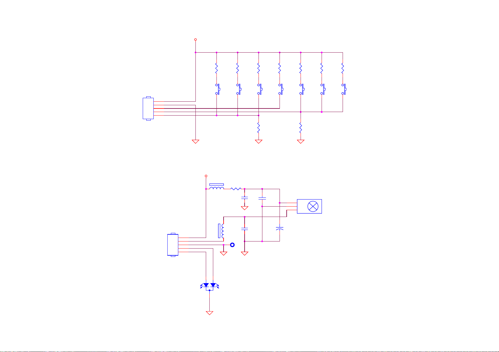
10.3 Key/IR Board
5VP
R608
15K
Menu
R607
5.1K
CH_Down
R606
2.2K
CH_UP
R605
10K
Power
R604
15K
VOL_Down
R603
5.1K
VOL_UP
R602
2.2K
Norcent LT2722
MODE_Sel
CN600
CONN
S605
5
4
3
2
1
CN600
CONN
GND
KEY_I_3
KEY_I_2
KEY_1_1
5
4
3
2
1
5VP
FB600
600 OHM
FB601
600 OHM
R609
100 1/16W
TP600 NC
FOR EMI
S600
R600
3.9K
C603
0.1uF
C600
100pF
S606
C601
0.1uF
C602
100uF/16V
S603
R601
3.9K
S604
D600
3
VCC
2
GND
1
DATA
S601
+
S602
D601
LED
76
Page 79

If you need more information on Computer and Electronic Repair, please visit these
in fact
websites to improve yourself.
http://www.fastrepairguide.com
http://www.protech2u.com
http://www.plasma-television-repair.com
http://www.lcd-television-repair.com
Happy Repairing!!
Highly Recommended Repair Ebook:
If you’re a LCD Monitor repairer, then this is the best guide for you.
Why? Because, the author revealed all his LCD Monitor Repairing
secrets for you. I think, with just few Repair tips you learned from
this guide you will get back your investment!
Click Here to read more.
This eBook will show you how to test the electronic component
correctly and accurately. Some of you may say that I don’t
need this eBook because it is too simple! Do you know that,
there is lots of testing electronic components secrets I have learned
from this guide? Do you know how to test a‘TRIAC’ correctly and
accurately? If you answer no then I guess you have to get this
EBook. Click Here to read more.
Are you tired of searching the service manuals to look for the value
of a burnt resistor? If the answer is YES, then this eBook is a ‘must
have’ guide for you. You can save a lot of time and be able to repair
customer’s Electronic equipment with burnt resistors in it.
Click here to read more.
 Loading...