

Page 1

LM929 & EN9250
LM929 EN9250
Page 2
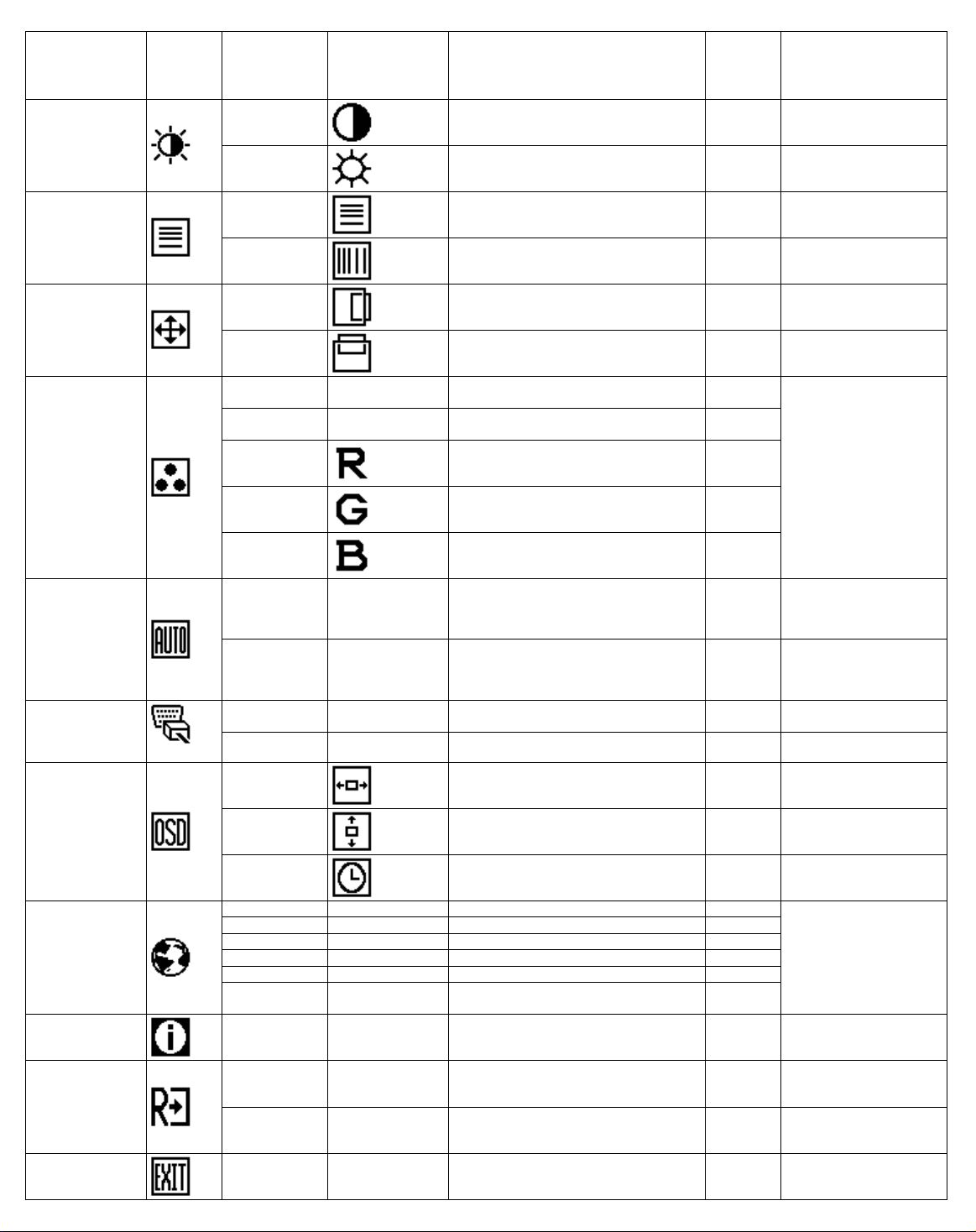
Main Menu Item
Luminance
Image Setup
Image Position
Color Temp.
Auto Config
(Analog-Only
Model)
Main Menu
Icon
Sub Menu Item Sub Menu Icon
Contrast
Brightness
Focus
Clock
H. Position
V. Position
Warm N/A
Cool N/A
User / Red
User / Green
User / Blue
Yes
No N/A
N/A
Description
Contrast from Digit al -regi ster. 0-100 Recall Cool Contrast Value
Backlight Adjustment 0-100
Adjust Picture Phase to reduce
Horizontal-Line noise
Adjust picture Cloc k to reduce VerticalLine noise.
Adjust the horizontal position of the
picture.
Adjust the vertical position of the picture. 0-100 Do Auto Config
Recall Warm Color Temperature from
EEPROM.
Recall Cool Color Temperature from
EEPROM.
Red Gain from Digital-regis t er. 0-100
Green Gain Digital-register. 0-100
Blue Gain from Digital-regi ster. 0-100
Auto Adjust the H/V P osition, Focus and
Clock of picture.
Do not execute Auto Config, return to
main menu.
Adjust
Range
0-100 Do Auto Config
0-100 Do Auto Config
0-100 Do Auto Config
N/A
N/A
N/A N/A
N/A N/A
Reset Value
Recall Cool Brightness
Value
The Color Temperature
will be set to Cool.
The User R/G/B
value(default is 100) will
not be Modified by Reset
function.
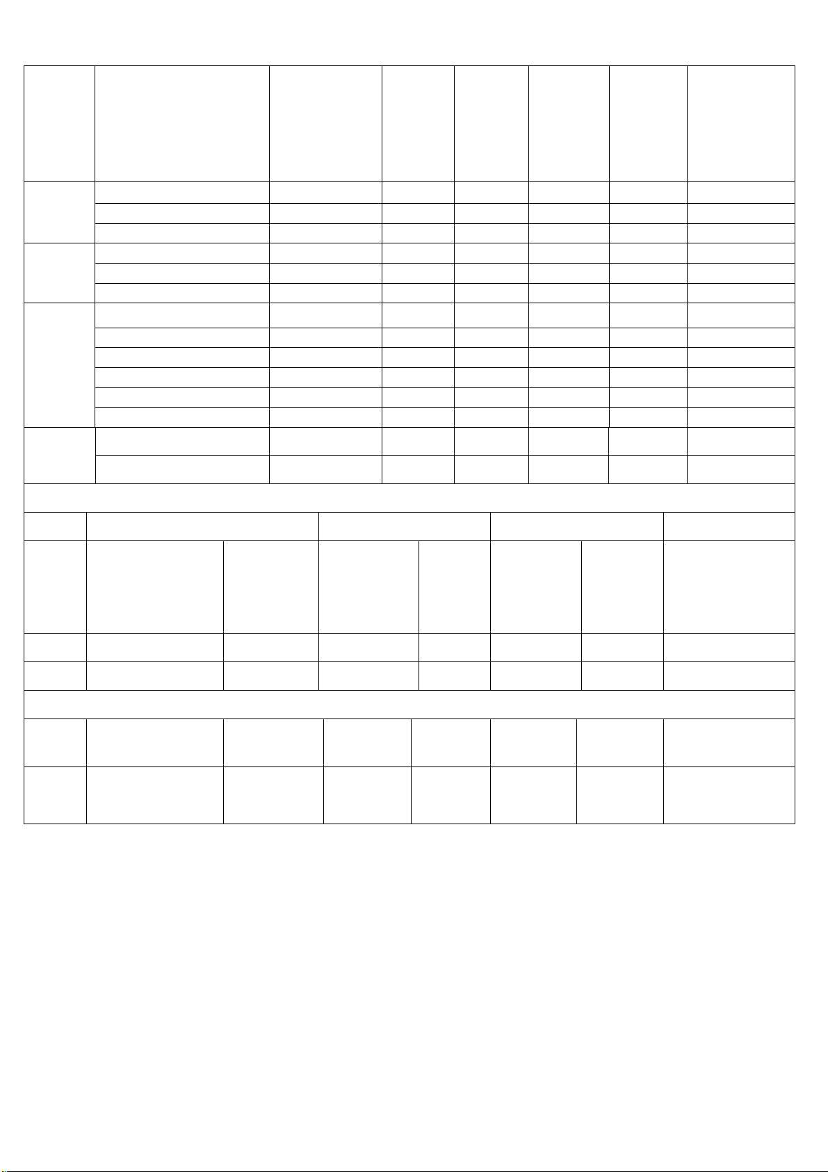
Input Select
(Dual-Input Model)
OSD Setup
Language
Information
Reset
Exit
Analog
Digital N/A Select input signal from digital (DVI) N/A N/A
H. Position
V. Position
OSD Timeout
English N/A Set OSD display language to Engli sh. N/A
Deutsch N/A Set OSD display language to German. N/A
Français N/A Set OSD display language to French. N/A
Español N/A Set OSD di splay language to Spain. N/A
Italiano N/A Set OS D di splay language to Italian. N/A
N/A
Information N/A
Yes N/A
No N/A
N/A N/A Exit OSD N/A N/A
N/A Select input signal f rom analog (D-Sub) N/A N/A
Adjust the horizontal position of the OSD. 0-100 50
Adjust the vertical position of the OSD. 0-100 50
Adjust the OSD timeout. 10-120 10
The Language will be set
to English.
Set OSD display language to Si mplified
Chinese.
Show the resolution, H/V frequenc y and
input port of current input t i ming.
Clear each old status of A utoconfiguration and set the c ol or
temperature to Cool.
Do not execute reset, return to m ai n
menu.
N/A
N/A N/A
N/A N/A
N/A N/A
Page 3

3. OPERATING INSTRUCTIONS
3.1 GENERAL INSTRUCTIONS
Press the power button to turn the monitor on or off. The other control buttons are located
at front panel of the monitor. By changing these settings, the picture can be adjusted to
your personal preferences.
The power cord should be connected.
-
Connect the video cable from the monitor to the video card.
-
Press the power button to turn on the monitor, the power indicato r will light up .
-
3.2 ADJUSTING THE PICTURE
I. Analog-Only Model II. Dual-Input Model, Analog Signal Input
III. Dual-Input Model, Digital Signal Input
Note:
is “ENVISION”
There is a difference of the LM929 and EN9250: LM929’ s LOGO is “AOC” and EN9250’ s LOGO
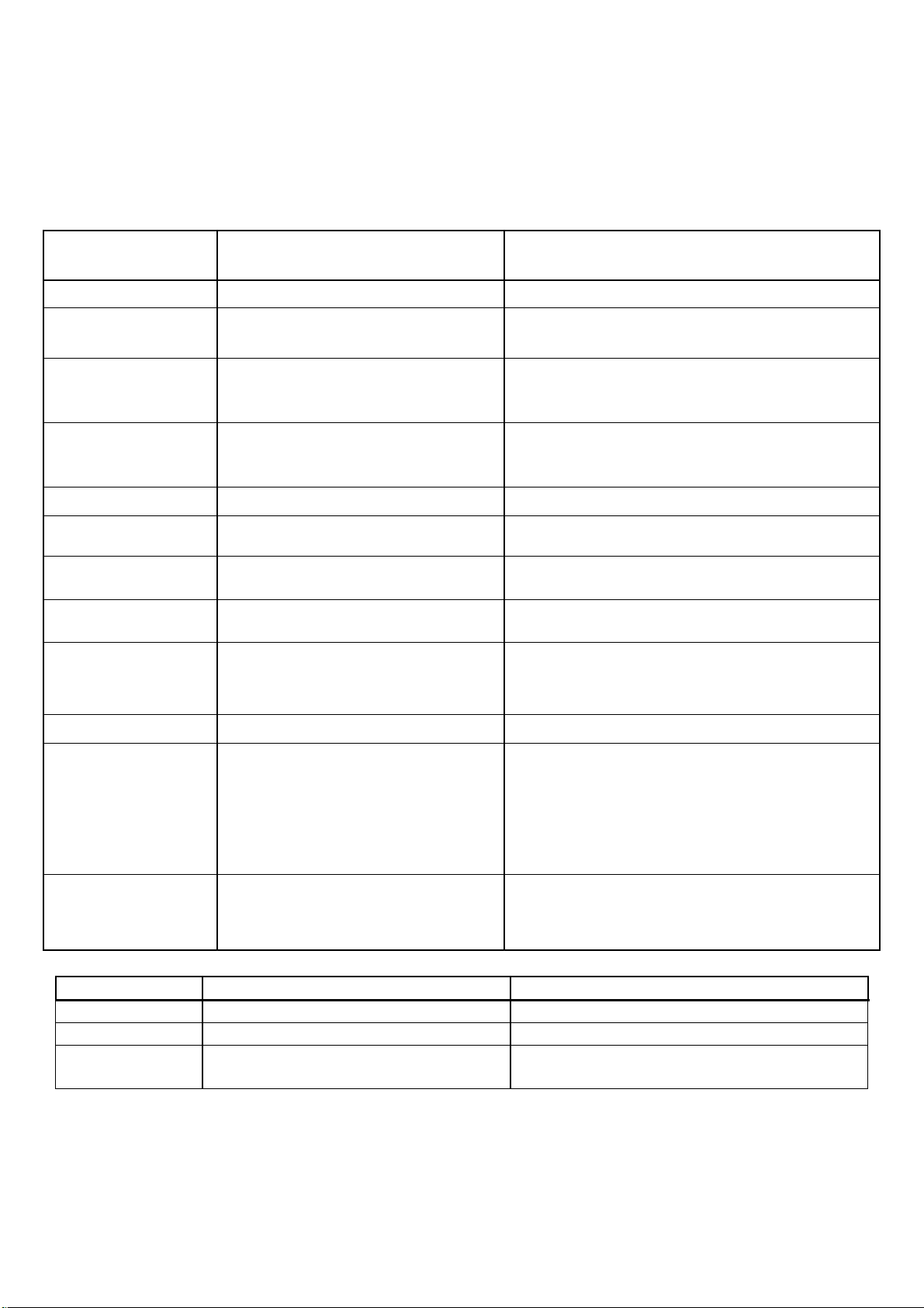
The description for control function :
Main Menu
Item
Luminance
Main
Menu
Icon
Sub Menu
Item
Contrast
Brightness
Sub Menu
Icon
Description
Contrast from Digital-
Backlight Adjustment 0-100
register.
Adjust
Range
0-100
Reset Value
Recall Cool
Contrast Value
Recall Cool
Brightness Value
Page 4
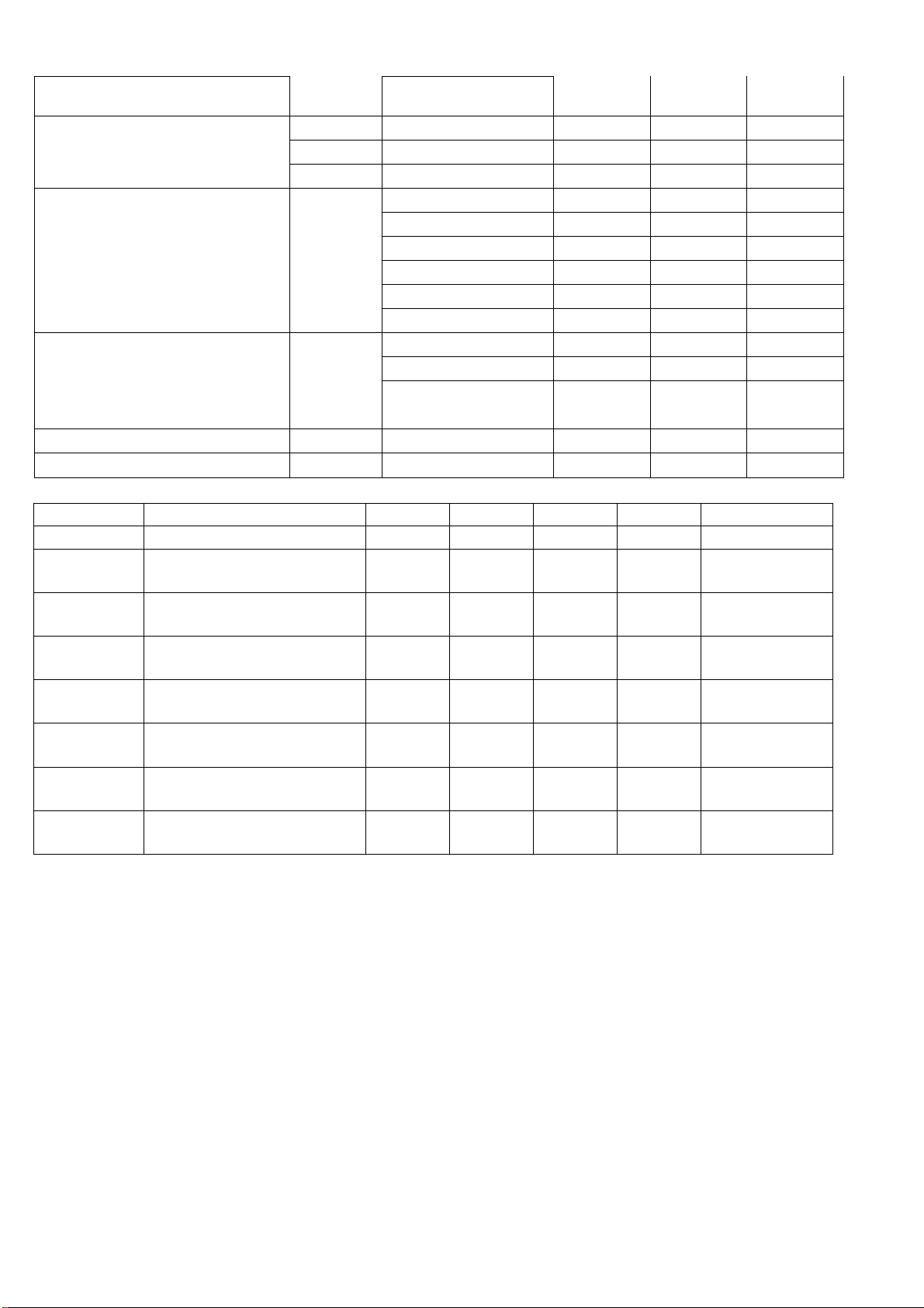
Mode Resolution Total
640x480@60Hz 800 x 525 31.469 N 59.940 N 25.175
VGA
SVGA
XGA
640x480@72Hz 832 x 520 37.861 N 72.809 N 31.500
640x480@75Hz 840 x 500 37.500 N 75.00 N 31.500
800x600@60Hz 1056 x 628 37.879 P 60.317 P 40.000
800x600@72Hz 1040 x 666 48.077 P 72.188 P 50.000
800x600@75Hz 1056x625 46.875 P 75.000 P 49.500
1024x768@60Hz 1344x806 48.363 N 60.004 N 65.000
1024x768@60Hz 1312x813 48.78 N 60.00 N 64.000
1024x768@70Hz 1328x806 56.476 N 70.069 N 75.000
1024x768@72Hz 1304x798 57.515 P 72.074 P 75.000
1024x768@75Hz 1328x804 60.200 N 74.90 N 80.000
1024x768@75Hz 1312x800 60.023 P 75.029 P 78.750
1280 x1024@60Hz 1688 x1066 64.000 N 60.000 N 108.000 SXGA
Nomin
al
Freque
ncy
+/-
0.5kHz
Sync
Polarity
Nominal
Freq.
+/- 1 Hz
Sync
Polarity
Nominal
Pixel
Clock(MHz)
1280 x1024@75Hz 1728 x1011 80.000 P 75.000 P 135.000
IBM MODES
Horizontal Vertical
Mode Resolution
DOS 720x400@70Hz 900 x 449 31.469 N 70.087 P 28.322
DOS 640x350@70Hz 800 x 449 31.469 N 70.087 P 25.175
VGA 640x480@67Hz 864x525 35.000 N 66.667 N 30.240
SVGA 832x624@75Hz 1152x667 49.725 N 74.551 N 57.2832
Note: All modes will automatically optimize the screen size with “ AUTO-config “ function, except 3
Dos- Modes : 720 x 400@70hz, 640x350@70hz ,640x400@70hz
Total
Nominal
Frequency
+/- .5kHz
MAC MODES
Sync
Polarity
Nominal
Freq.
+/- 1 Hz
Sync
Polarity
Nominal
Pixel
Clock(MHz)
4.3 DIGITAL CONTROL OPERATION
Signals used for mode detection:
- Nominal horizontal frequency
- Nominal vertical frequency
- Horizontal sync. Pulse polarity
- Vertical sync. Pulse polarity
The tolerance for detecting the horizontal frequency is between ±1KHz from center frequency
The tolerance for detecting the vertical frequency is between ±0.5hz from center frequency
FACTORY PRE-SET MODES FOR ANALOG INPUT
Starting the “ RESET” function in the OSD-MENU will clear all old settings of auto configuration in
preset modes & OSD back to center & Language set to English
FACTORY PRE-SET MODES FOR DIGITAL INPUT
Page 5
Starting the “ RESET” function in the OSD-MENU will auto-centering the Image& OSD back to center &
Language set to English
PROTECTION CIRCUIT
Missing or improper sync pulses will not damage the monitor. Additionally, under these conditions, the
monitor shall not cause damage to the driving source
4.4 POWER SUPPLY REQUIREMENT
4.4.1 INPUT REQUIREMENT
PARAMETER RANGE CONDITION
Input Voltage 100 to 240VAC RMS Universal input full range
Input Frequency
Input Current Less than 2.0 Amps RMS
Less than 1.0 Amps RMS
Input Power Less than 40 Watts
Power factor > 0.5
Inrush Current Less than 30 A peak
Less than 50 A peak
60Hz @ 100VAC to 50Hz
@ 240VAC
Input voltage 120 VAC RMS ; 60
Hertz
Input voltage 100 VAC RMS ; 60 Hertz.
Parameter must be reached within 3 seconds
of turn-on.
Input voltage 220 VAC RMS ; 50 Hertz.
Parameter must be reached within 3 seconds
of turn-on.
Input voltage 100 VAC RMS ; 60 Hertz at all
Phase(0, 90, 180, 270 degree)
Input voltage 240 VAC RMS ; 50 Hertz at all
Phase(0, 90, 180, 270 degree)
Fuse should be located internal to
Input Fusing
Leakage Current
Hi-Pot
Primary to Safety Ground 1.5KVAC for 1 Minute(leakage current
the adapter, easily accessible
when the cover is removed
Less than 3.5 mA Input voltage 240 Volts RMS ; 50 Hertz
Primary to secondary 1.5KVAC for 1 Minute(leakage current
Fuse must be UL/CSA approved. Fuse value
must no have to change for 115 VAC or 230
VAC operation
10mA)
1.8KVAC for 1 Minute(leakage current
10mA)
3.0KVAC for 1 Minute(leakage current
10mA)
without Y-cap & Coupling cap.
10mA)
1.8KVAC for 1 Minute(leakage current
10mA)
4.4.2 OUTPUT REQUIREMENT
PARAMETER RANGE CONDITION
DC Out 12VDC ± 5% Min 0A Max 3.75A
Load Regulation 12.0V ± 5% 11.4 to 12.6VDC
Dynamic Load
Regulation
Any frequency up to 250Hz(duty
50%)
±5% for 10% to 100%, 100% to 10% load
change for +12Vdc
Page 6
Contrast ratio Normal Direction 400 600
[m sec] Raising Time – 15 25
Response Time (Note 1)
Color Coordinates(CIE) White
White Luminance at CCFL
7.0mA
(central point)
Luminance Uniformity(Note 2) [%] 75 80 –
Crosstalk (in 75Hz)(Note 3) [%] 1.5
[m sec] Falling Time – 10 15
[m sec] Raising +Falling – 25 40
Red x 0.604 0.634 0.664
Red y 0.324 0.354 0.384
Green x 0.278 0.308 0.338
Green y 0.576 0.606 0.636
Blue x 0.108 0.138 0.168
Blue y 0.057 0.087 0.117
White x 0.28 0.31 0.34
[cd/]
White y 0.3 0.33 0.36
200 250 –
4.5.4 PARAMETER GUIDE LINE FOR CFL INVERTER.
SYMBOL PARAMETER MIN TYP MAX UNITS CONDITION
(L255) White Luminance 200 250 –
ISCFL CCFL standard current 6.5 7 7.5
IRCFL CCFL operation range 3 7 7.5
FCFL
ViCFL
(0)
ViCFL
(25)
VCFL
PCFL CCFL Power consumption 20.16 23.4 [Watt]
Note1: CCFL frequency should be carefully determined to avoid interference between inverter and TFT
LCD
CCFL Frequency 40 50 60 [KHz]
CCFL ignition Voltage 2000
CCFL ignition Voltage 1500
CCFL Discharge Voltage
(Reference)
720 780
[cd/] (Ta=25)
[mA]
rms
[mA]
rms
[Volt]
rms
[Volt]
rms
[Volt]
rms
(Ta=25)
(Ta=25)
(Ta=25)
Note 1
(Ta=0)
Note 2
(Ta=25)
Note 2
(Ta=25)
Note 3
(Ta=25)
Note 3
Note 2: CCFL inverter should be able to give out a power that has a generating capacity of over 2000
voltage
Note 3:Calculator value for reference (ICFL x VCFL=PCFL)=PCFL
Note 4:Lamp soldering method is required to use “Hook Soldering”
Page 7

Page 8
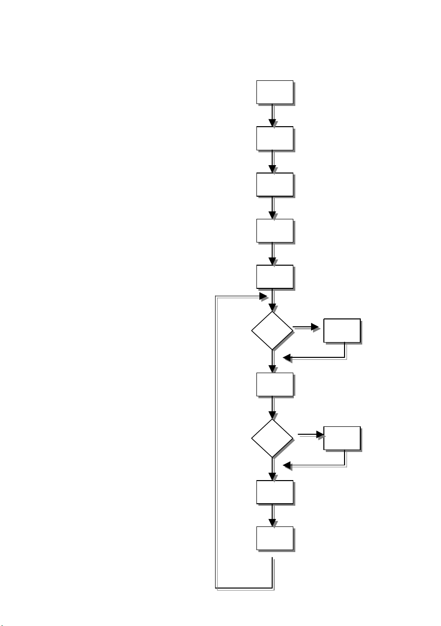
5.2 SOFTWARE FLOW CHART
(1)
(2)
(3)
(4)
(5)
N
N
(8)
(9
(11)
(12)
Y
(7) (6
Y
(10)
Page 9

1. Initialize MCU settings, including I/O, Timer, ISR and Serial Port settings.
2. Read EEPROM content to recover monitor settings, including brightness, contrast, color
temperature and OSD position etc.
3. Initialize system variable, including system flag, OSD timeout counter, burin mode status… etc.
4. Initialize OSD menu variable for user operation
5. Initialize device on the board, now only MST scalar chip will be initialized
6. Check if system is in power off status from first AC power up. If yes, then go to 7, else go to 8.
7. If yes, system will be forced to enter power off status Mode detection
8. Check if input timing has been changed, if yes then go to 10, else go to 11
9. Setup MST scalar for display according input timing
10. OSD handler for OSD operation.
11. Debug handler, only debug only
Page 10

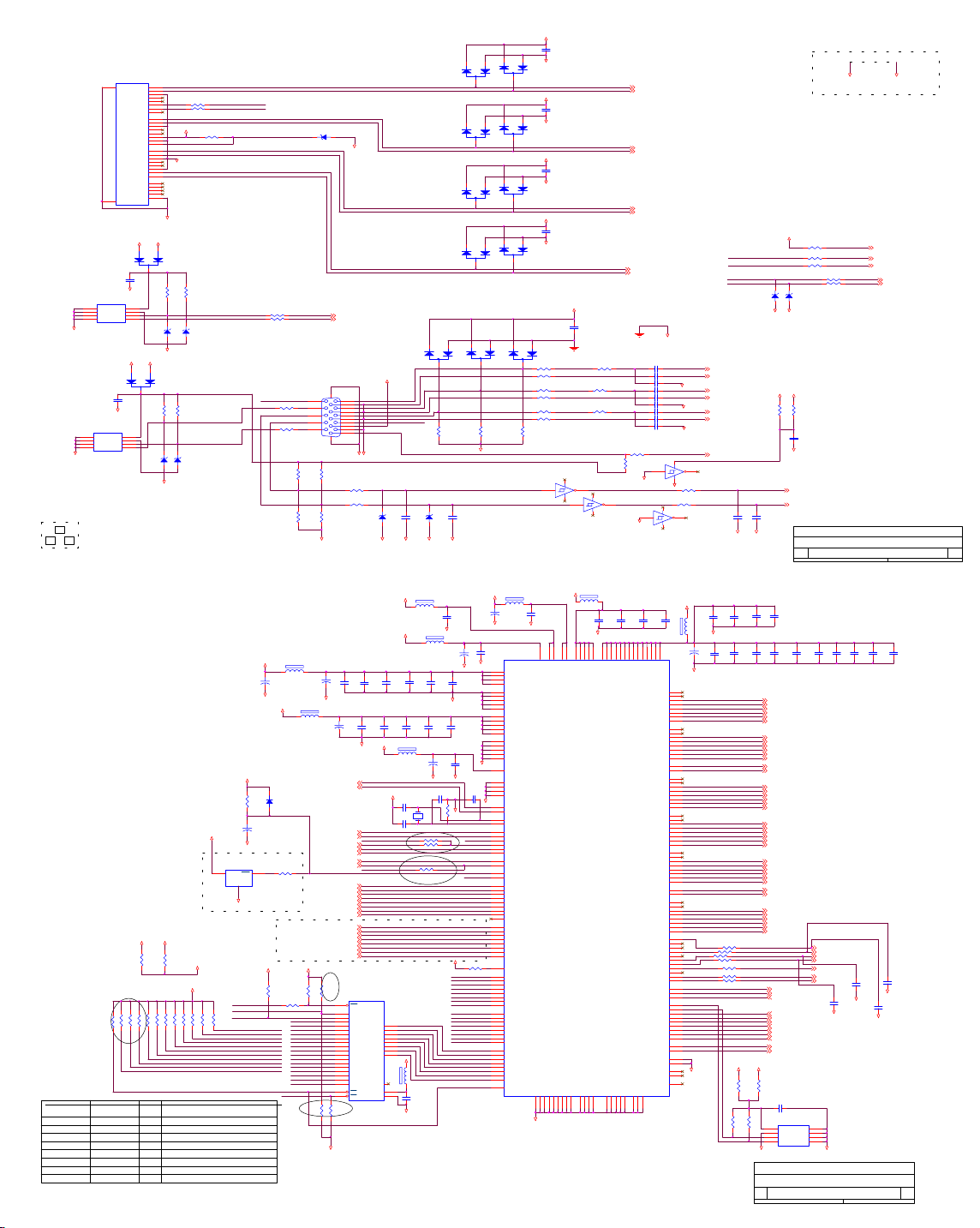
5.3 ELECTRICAL BLOCK DIAGRAM
5.3.1 SCALAR BOARD BLOCK DIAGRAM
Flash Memory
A290011TL-70
(U601)
LCD Interface
Scalar MST8131A
(Include MCU,ADC,OSD)
(CN503)
(U9)
(U401)
OSD
Control
Interface
(CN602)
24C02
EPR_SDA
EPR_SCL
EEPROM
24C16
(U602)
RXD
TXD
DB15_SDA,
DB15_SCL
RGB
D-Sub
Connector
(CN301)
EEPROM
24C02
(U301)
H sync
V sync
DVI-I only
Connector
(CN302)
EEPROM (D-I only)
24C02
(U302)
Page 11

5.3.2 INVERTER/POWER BOARD BLOCK DIAGRAM
Inverter Block Diagram
Page 12

PWPC1942AUE2
Power Block Diagram
Page 13

1. MONITOR SPECIFICATIONS
ITEM SPECIFICATION
Display Area (mm) 376.32(H) x 301.056(V) (19.0-inch diagonal)
Number of Pixels 1280(H) x 1024(V)
Pixel Pitch (mm) 0.294(H) x 0.294(V)
Color Pixel Arrangement RGB vertical stripe
Display Mode Normally white TN
Number of Colors 262144(6bit/color)
Brightness (cd / m²) 250cd/ m² (Typ.)
Viewing Angle 55-75(H), 30-83(V)( Typ)
Wide Viewing Angle Technology Optical Compensation Film
Surface Treatment Anti-glare
Electrical interface RSDS (1 pixel/clock)
Total Module Power (W) 10.5(Typ.)
Optimum Viewing Angle 6 O’clock
Module Size (mm) 404.2(W) x330(H) x20(D)(Typ)
Module Weight (kg) 7.8
Backlight Unit CCFL, 2 tables, edge- light (top/bottom)
2. LCD MONITOR DESCRIPTION
The LCD MONITOR will contain an main board, an inverter/power board, keypad board which house
the flat panel control logic, brightness control logic and DDC.
The power board will provide AC to DC Inverter voltage to drive the backlight of panel and the main
board chips each voltage.
Power board
(include: inverter)
AC-IN
100V-240V
Monitor Block Diagram
CCFL Drive.
Main Board
Keyboard
Flat Panel and
CCFL backlight
HOST Computer
RS232 Connector
For white balance
adjustment in factory
mode
Video signal, DDC
Page 14

5.3.2 INVERTER/POWER BOARD BLOCK DIAGRAM
Inverter Block Diagram
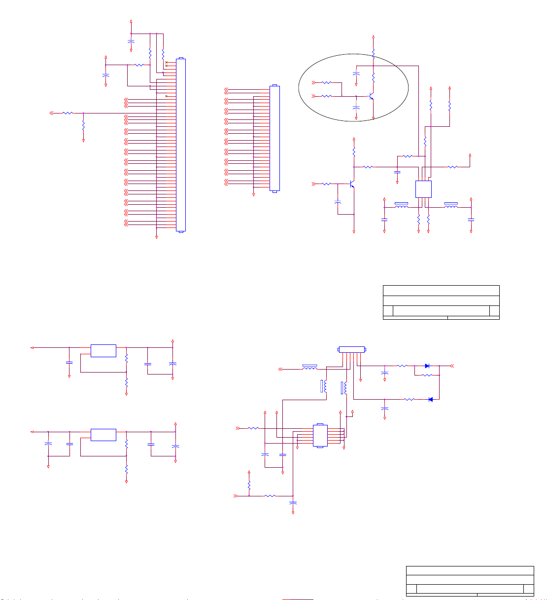
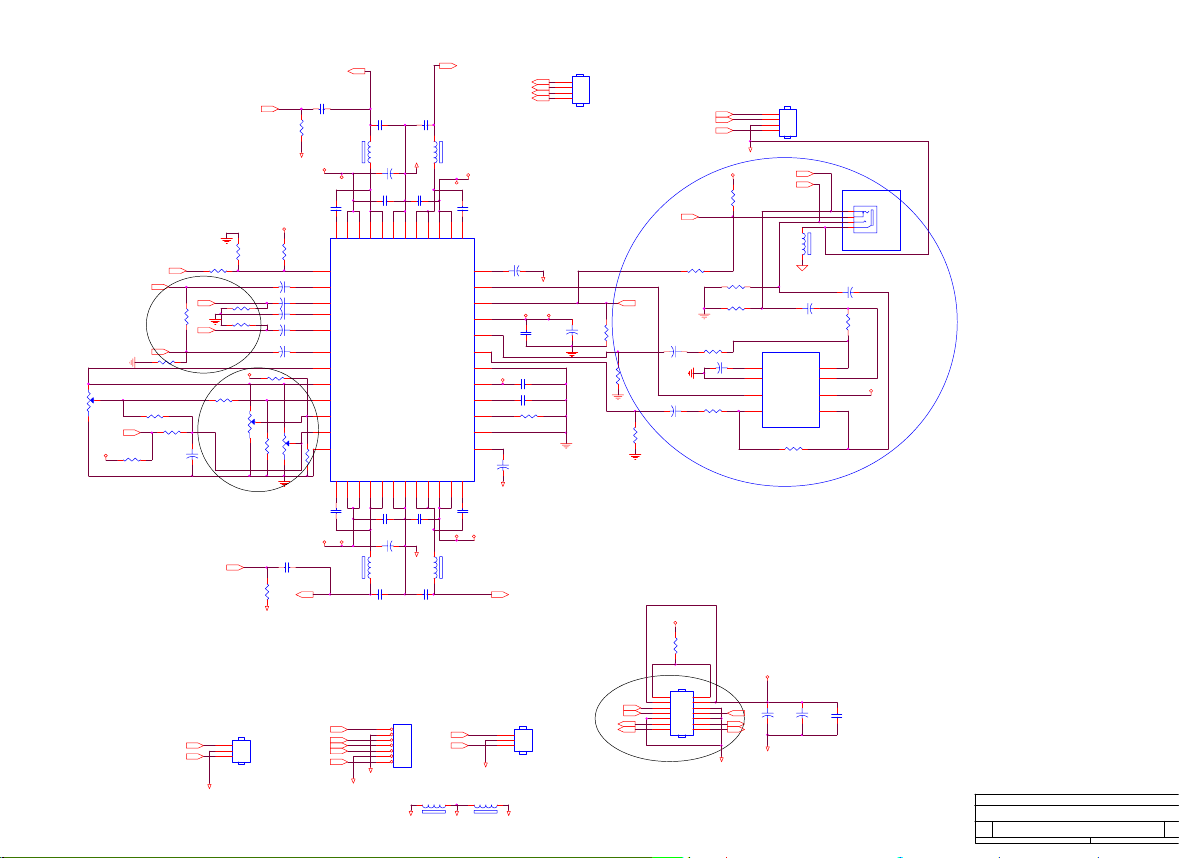
Page 15
6.1 MAIN BOARD
CN1
1
26
A_GND
T2-
2
T2+
3
SGND
4
T4-
5
T4+
R1 47£[ 1/16W
6
25
A_GND
0.1uF/16V
U1
VCCA0
2
A1A2WP
3
SCL
4
SDA
GND
M24C02WMN6
GND
0.1uF/16V
GND
U2
VCCA0
237
A1A2WP
SCL
4
SDA
GND
M24C02WMN6
GND
SOT23
3
2
1
R53
R220
10K£[ 1/16W
NC
BOOTSTRAP SIGNALS
ADDRESS
ROM_ADDR(4:0)
ROM_ADDR5 x
ROM_ADDR6
ROM_ADDR7
ROM_ADDR8
ROM_ADDR9
ROM_ADDR(12:10)
ROM_ADDR13
ROM_ADDR14
NAME
USER_BITS(4:0)
Reserved
SCLPOL
HOST_PROTOCOL
HOST_PORT_EN
OCM_START
USER_BITS(7:5)
OSC_SEL
OCM_ROM_CFG(1)
A_HSYNC
C5
GND
VGA_5V
C12
81
6
5
NC
A_VSYNC
A_GREEN
DDCCLK
DDCDAT
DVI_5V
81
7
6
5
2
R221
7
8
9
T1-
10
T1+
11
SGND
12
T3-
13
T3+
14
+5V
15
GND
16
HPD
17
T0-
18
T0+
19
SGND
20
T5-
21
GND
T5+
22
SGND
23
TC+
24
TC-
C1
A_RED
C2
C3
A_BLUE
C4
27
A_GND
AGND
+5V
1
2
D9
BAT54C-GS08
3
R11
R12
10K£[ 1/16W
MLL5232B 5.6V
GND
+5V
1
D13
BAT54C-GS08
DDC_5V
3
R20
10K£[ 1/16W
MLL5232B 5.6V
ZD6
GND
+5V
+3V3
R49
R50
NC
0£[ 1/16W
R61
R60
R62
R67
R222
NC
NC
NC
NC
NC
NC
SET
x
Available for reading from a status register
If using 6-wire host protocol, program this bit to 0
Determines polarity of HCLK signal
x
If using 6-wire host protocol, program this bit to 1
0
1
GPIO(22:16) is on "Host Port" pins
1
1 = OCM becomes active after OCM_CLK is stable
Available for reading from a status register
x
0 = XTAL and TCLK pins are connected
0
1 = All 48K of ROM is in external ROM
1
R2 47£[ 1/16W
DVI_5V
R3 10K£[ 1/16W
HOT_PLUG
10K£[ 1/16W
MLL5232B 5.6V
ZD5
ZD4
R21
10K£[ 1/16W
DDC_SCL_A1
MLL5232B 5.6V
ZD7
+PV
+PV
R64
R63
10K£[ 1/16W
DESCRIPTION
DDC_SDA_A1
+3V3
R65
10K£[ 1/16W
DDC_SCL_D1
DDC_SDA_D1
DIGITAL USE
4.7K£[ 1/16W
R66
10K£[ 1/16W
RMADDR14
RMADDR9
RMADDR8
RMADDR10
RMADDR11
RMADDR3
RMADDR4
RMADDR12
RMADDR2
RMADDR1
RMADDR0
+5V
C1
0.1uF/16V
1
2
1
2
RX2-IN
RX2+IN
DDC_SCL_D1
DDC_SDA_D1
RX1-IN
RX1+IN
ZD1
MLL5232B 5.6V
RX0-IN
RX0+IN
RXC+IN
RXC-IN
R13 NC GND
R14 NC
UART_DI
R19 47£[ 1/16W
HSin
VSin
R28
47£[ 1/16W
R34
2K£[ 1/16W
R42
NC
GND
DDC_SCL_D 3
DDC_SDA_D 3
VGA_5V
CN2
1617
DB15
1
11
12
13
14
15
AGND
R35
2K£[ 1/16W
R43
NC
6
2
7
3
8
4
9
5
10
GND
Pins 6/7/8 are R/G/B
return lines resp.
R38 47£[ 1/16W
R40 47£[ 1/16W
Rin
Gin
Bin
UART_DO
AGND
MLL5232B 5.6V
ZD8
C18
NC
AGND
GND
+3V3
FB4
600 OHM
+3V3
+3V3
C48
22uF/16V
+3V3
R46
+
GND
U5 TCM809SENB713/NC
VCC
RST
1
GND
10K£[ 1/16W
ROM_WE
BANK1
BANK0
23
R56
C70
22uF/16V
FB7
600 OHM
+3V3
R48
NC
DIGITAL PORT
10K£[ 1/16W
ROMCE
R57
R59
0£[ 1/16W
RMADDR15
RMADDR14
RMADDR13
RMADDR12
RMADDR11
RMADDR10
RMADDR9
RMADDR8
RMADDR7
RMADDR6
RMADDR5
RMADDR4
RMADDR3
RMADDR2
RMADDR1
RMADDR0
22uF/16V
FB8
600 OHM
+PV
C49
GND
C57
22uF/16V
R218
NC
R219
0£[ 1/16W
+
C50
0.1uF/16V
+
PPWR4
PBIAS7
STDBY7
VGA_PG2
CTRLP12V4
DDC_SDA_A2
DDC_SCL_A2
DDC_SCL_D2
DDC_SDA_D2
RED+2
RED-2
GREEN+2
GREEN-2
BLUE+2
BLUE-2
HS2
VS2
RXC+2
RXC-2
RX2+2
RX2-2
RX1+2
RX1-2
RX0+2
RX0-2
31
WE
30
NC/A17
2
A16
3
A15
29
A14
28
A13
4
A12
25
A11
23
A10
26
A9
27
A8
5
A7
6
A6
7
A5
8
A4
9
A3
10
A2
11
A1
12
A0
24
OE
22
CE
R225
10K£[ 1/16W
32-Pin PLCC Socket
FLASH/ Prom-Jet Socket
+
GND
D14
LL4148
Reset
Circuit
+PV
GND
0.1uF/16V
0.1uF/16V
W39F010P
3V3_RGB
C53
C52
C51
0.1uF/16V
0.1uF/16V
3V3_DVI
C60
C59
C58
0.1uF/16V
0.1uF/16V
FB9
+2V5
600 OHM
C64
22uF/16V
+3V3
X1
C68
14.318MHz
12
5pF/50V
C69
5pF/50V
ROMCE
R223 0£[ 1/16W
R224 NC
BANK1
R217 NC
RESET
U6
21
RMDATA7
DQ7
RMDATA6
20
DQ6
RMDATA5
19
DQ5
RMDATA4
18
DQ4
RMDATA3
17
DQ3
RMDATA2
15
DQ2
14
RMDATA1
DQ1
RMDATA0
13
DQ0
+PV
1
FB10
NC
600 OHM
32
VCC
16
GND
C71
0.1uF/16V
GND
2
3
R29
75£[ 1/16W
75-ohm terminating resistor
very close to the VGA
conn.
(8 mil)
MLL5232B 5.6V
ZD9
GND
FB6
600 OHM
22uF/16V
C54
0.1uF/16V
C61
0.1uF/16V
+
0.1uF/16V
GND
C66
NC
1
AGND
AGND
C65
R47
NC
+3V3
0.1uF/16V
GND
C35
GND
RMDATA6
RMDATA5
RMDATA4
RMDATA3
RMDATA2
RMDATA1
RMDATA0
ROM_OEn
C25
0.1uF/16V
0.1uF/16V
GND
D11
BAV99
C19
NC
C55
C62
RMADDR15
RMADDR14
RMADDR13
RMADDR12
RMADDR11
RMADDR10
RMADDR9
RMADDR8
RMADDR7
RMADDR6
RMADDR5
RMADDR4
RMADDR3
RMADDR2
RMADDR1
RMADDR0
3
2
3
2
3
2
3
2
+
GND
C67
NC
XTAL
TCLK
BANK0
ROM_WE
R51 1K£[ 1/16W
AGND
22uF/16V
GND
1
1
1
1
3
R30
75£[ 1/16W
+3V3
C23
GND
C37
0.1uF/16V
AGND
AGND
D2
BAV99
D4
BAV99
D6
BAV99
D8
BAV99
153
149
145
141
156
155
152
148
144
135
132
126
120
112
136
129
123
117
114
138
172
168
163
137
175
174
108
109
107
150
151
146
147
142
143
176
177
154
133
134
118
119
124
125
130
131
113
180
181
182
183
184
187
188
189
190
191
192
193
194
195
196
197
200
201
202
203
204
205
206
207
208
D10
BAV99
+
3V3_SDDS
78
79
90
91
92
93
89
88
81
3
2
3
2
3
2
3
2
FB5
600 OHM
GM5126
AVDD_ADC
AVDD_RED
AVDD_GREEN
AVDD_BLUE
SGND_ADC
AGND_ADC
AGND_RED
AGND_GREEN
AGND_BLUE
AVDD_RXC
AVDD_RX0
AVDD_RX1
AVDD_RX2
AVDD_IMB
AGND_RXC
AGND_RX0
AGND_RX1
AGND_RX2
AGND_IMB
VDD_RXPLL_2.5
AVSS_RPLL
AVSS_DDDS
AVSS_SDDS
GND_RXPLL
PPWR
PBIAS
TCLK
XTAL
GPIO20/HDATA3
GPIO19/HDATA2
GPIO18/HDATA1
GPIO17/HDATA0
GPIO16/HFS
GPIO22/HCLK
GPIO14/DDC_SCL
GPIO15/DDC_SDA
RESETn
GPIO11/ROM_WEn
RED+
REDGREEN+
GREENBLUE+
BLUEHSYNC
VSYNC
ADC_TEST
RXC+
RXCRX2+
RX2RX1+
RX1RX0+
RX0-
REXT
ROM_ADDR15
ROM_ADDR14
ROM_ADDR13
ROM_ADDR12
ROM_ADDR11
ROM_ADDR10
ROM_ADDR9
ROM_ADDR8
ROM_ADDR7
ROM_ADDR6
ROM_ADDR5
ROM_ADDR4
ROM_ADDR3
ROM_ADDR2
ROM_ADDR1
ROM_ADDR0
ROM_DATA7
ROM_DATA6
ROM_DATA5
ROM_DATA4
ROM_DATA3
ROM_DATA2
ROM_DATA1
ROM_DATA0
ROM_OEn
GND
D1
BAV99
+5V
C2
0.1uF/16V
1
GND
D3
BAV99
+5V
C3
0.1uF/16V
1
GND
D5
BAV99
+5V
C4
0.1uF/16V
1
GND
D7
BAV99
+5V
C6
0.1uF/16V
1
ADC_AGND
D12
BAV99
100£[ 1/16W
R15
3
100£[ 1/16W
R16
100£[ 1/16W
R17
R18
R24
R27
R31
75£[ 1/16W
3V3_DDDS
C24
0.1uF/16V
GND
100£[ 1/16W
100£[ 1/16W
100£[ 1/16W
1 2
147
74LCX14
FB2 0£[ 1/16W
FB3 0£[ 1/16W
U3A
5 6
+3V3
FB18
600 OHM
Close to respective power Pins
U4
77
173
RVSS
102
AVDD_RPLL
RVSS
RVSS
179
169
167
164
162
VDD_SDDS
VDD_DDDS
AVDD_SDDS
AVDD_DDDS
RVSS
EAVSS_RS
EAVSS_RS
AVSS_RS
OAVSS_RS
OAVSS_RS
199142638486085
171
76
VDD_DPLL
36
101
RVDD
CVSS
RXC+ 3
RXC- 3
ADC_AGND
(10 mil, ©Ô¥-¦æ½u)
FB1 0£[ 1/16W
R32
4.7K 1/16W
VGA_CONN
R33
10K£[ 1/16W
DDC_5V
U3C
147
74LCX14
AGND
C27
C28
GND
158
160
19813253747593584110
115
121
127
178
RVDD
RVDD
RVDD
AVDD_RS
VDD_RX2_2.5
VDD_RX1_2.5
VDD_RX0_2.5
VDD1_ADC_2.5
VDD2_ADC_2.5
EAVDD_RS_2.5
EAVDD_RS_2.5
GPIO10/TCON_ROE3
GPIO9/TCON_ROE2
GPIO21/TCON_FSYNC
GPIO12/NVRAM_SDA
GPIO13/NVRAM_SCL
GPIO6/TCON_SHC
GPIO7/TCON_TDIV
GPIO5/UART_DO
CVSS
CVSS
CVSS
GND1_ADC
GND2_ADC
GND_RX2
GND_RX1
GND_RX0
VSS_DPLL
111
186
157
159
116
122
128
170
RX2- 3
RX2+ 3
RX1- 3
RX1+ 3
RX0- 3
RX0+ 3
C7
C8
C9 NC
C10
C11
C13 NC
C14
C15
C16 NC
AGND
9 8
C29
CVDD_2.5
CVDD_2.5
OAVDD_RS_2.5
OAVDD_RS_2.5
OCH11P_RS
OCH11N_RS
OCH10P_RS
OCH10N_RS
OCH9P_RS
OCH9N_RS
OCH8P_RS
OCH8N_RS
OCH7P_RS
OCH7N_RS
OCH6P_RS
OCH6N_RS
OCH5P_RS
OCH5N_RS
OCH4P_RS
OCH4N_RS
OCLKP_RS
OCLKN_RS
OCH3P_RS
OCH3N_RS
OCH2P_RS
OCH2N_RS
OCH1P_RS
OCH1N_RS
OCH0P_RS
OCH0N_RS
ECH11P_RS
ECH11N_RS
ECH10P_RS
ECH10N_RS
ECH9P_RS
ECH9N_RS
ECH8P_RS
ECH8N_RS
ECH7P_RS
ECH7N_RS
ECH6P_RS
ECH6N_RS
ECH5P_RS
ECH5N_RS
ECH4P_RS
ECH4N_RS
ECLKP_RS
ECLKN_RS
ECH3P_RS
ECH3N_RS
ECH2P_RS
ECH2N_RS
ECH1P_RS
ECH1N_RS
ECH0P_RS
ECH0N_RS
TCON_OSP
TCON_OPOL
TCON_OINV
TCON_RSP2
TCON_RSP3
TCON_RCLK
TCON_ROE
TCON_ESP
TCON_EINV
TCON_EPOL
DHS/TCON_LP
GPIO8/IRQINn
GPIO0/PWM0
GPIO1/PWM1
GPIO2/PWM2
GPIO3/TIMER1
GPIO4/UART_DI
Reserved
Reserved
CLKOUT
VSS_DDDS
VSS_SDDS
166
161
AGND
0.01uF/50V
0.01uF/50V
0.01uF/50V
0.01uF/50V
0.01uF/50V
0.01uF/50V
6/24
VGA_PLUG
147
3 4
AGND
147
U3D
74LCX14
C30
FB19
600 OHM
185
CVDD_2.5
CVDD_2.5
68
67
66
65
64
63
62
61
58
57
56
55
54
53
52
51
50
49
46
45
44
43
42
41
40
39
34
33
32
31
30
29
28
27
24
23
22
21
20
19
18
17
16
15
12
11
10
9
8
7
6
5
69
71
70
72
73
74
75
1
2
3
4
80
105
106
82
83
94
95
96
97
98
103
104
99
100
86
87
139
N/C
165
N/C
140
AGND
22uF/16V
74LCX14
R41
+2V5
C36
AGND
AGND
U3B
R39 0£[ 1/16W
GND
SDA
SCL
GPIO0/PWM0
GPIO2
GPIO3
GPIO6
GPIO7
GND
0£[ 1/16W
+
GND
GND
DVI_5V
R4 NC
DDC_SCL_A1
R5 100£[ 1/16W
DDC_SDA_A1
R6 100£[ 1/16W
UART_DO
UART_DI
MLL5232B 5.6V
ZD2
GND
RED+ 3
RED- 3
GREEN+ 3
GREEN- 3
BLUE+ 3
BLUE- 3
VGA_PG 3
C33
0.1uF/16V
GND
Close to respective power Pins
C47
0.1uF/16V
OD22P
OD22N
OD21P
OD21N
OD20P
OD20N
OD12P
OD12N
OD11P
OD11N
OD10P
OD10N
OCLK_RS_P
OCLK_RS_N
OD02P
OD02N
OD01P
OD01N
OD00P
OD00N
ED22P
ED22N
ED21P
ED21N
ED20P
ED20N
ED12P
ED12N
ED11P
ED11N
ED10P
ED10N
ECLK_RS_P
ECLK_RS_N
ED02P
ED02N
ED01P
ED01N
ED00P
ED00N
R87 33£[ 1/16W
R88 33£[ 1/16W
R89 33£[ 1/16W
R92 33£[ 1/16W
R52 22£[ 1/16W
R54 22£[ 1/16W
R55 22£[ 1/16W
DVI_PLUG
+5V
+3V3
R25
NC
AGND
U3VCC
VS 3
HS 3
C20
C21
NC
NC
AGND
AGND
Title
Size Document Number Rev
Date: Sheet
C31
C34
C32
0.1uF/16V
0.1uF/16V
0.1uF/16V
C38
+3V3
R70
10K£[ 1/16W
SCL
SDA
C41
C40
C39
0.1uF/16V
0.1uF/16V
0.1uF/16V
ADD DEN SIGNAL PIN 4/28
OD22P 4
OD22N 4
OD21P 4
OD21N 4
OD20P 4
OD20N 4
OD12P 4
OD12N 4
OD11P 4
OD11N 4
OD10P 4
OD10N 4
OCLK_RS_P 4
OCLK_RS_N 4
OD02P 4
OD02N 4
OD01P 4
OD01N 4
OD00P 4
OD00N 4
ED22P 4
ED22N 4
ED21P 4
ED21N 4
ED20P 4
ED20N 4
ED12P 4
ED12N 4
ED11P 4
ED11N 4
ED10P 4
ED10N 4
ECLK_RS_P 4
ECLK_RS_N 4
ED02P 4
ED02N 4
ED01P 4
ED01N 4
ED00P 4
ED00N 4
TCON_OSP
TCON_RSP2
TCON_RCLK
TCON_ROE
TCON_ESP
TCON_EPOL
TCON_LP
LED_ORANGE 5
LED_GRN 5
DVI_PLUG 2
GPIO8 5
PWM0 7
VOLUME 7
GPIO2 5
GPIO3 5
GPIO6 5
GPIO7 5
GPIO4UART_DI
GPIO5UART_DO 2
+5V
R69
R68
NC
0£[ 1/16W
C72
0.1uF/16V
R71
U7
8
VCC
7
10K£[ 1/16W
WP
6
SCK
M24C16-MN6T
GND
AOC
Title
gm5126
Size Document Number Rev
gm5126 A
C
Date: Sheet
Connect two grounds at one single point only.
GND
AGND
DVI_PLUG 3
DDC_SCL_A 3
C43
0.1uF/16V
GND
22pF/NC
DDC_SDA_A 3
GPIO5UART_DO
GPIO4UART_DI 3
C46
C45
C44
0.1uF/16V
0.1uF/16V
C79
0.1uF/16V
0.1uF/16V
C76
C74
22pF/NC
22pF/NC
GND
GND
C86
22pF/NC
GND
R8 100£[ 1/16W
R10 100£[ 1/16W
MLL5232B 5.6V
ZD3
R26
0£[ 1/16W
C17
0.1uF/16V
AOC
ANALOG&DIGITAL INPUT
gm5126 A
C
C42
0.1uF/16V
TCON_OSP 4
TCON_RSP2 4
TCON_RCLK 4
TCON_ROE 4
TCON_ESP 4
TCON_EPOL 4
TCON_LP 4
2
1
A0
2
A1
3
A2
45
VSSSI
GND
38ÐÇÆÚ¶þ, ÆßÔÂ 22, 2003
of
3
of
28ÐÇÆÚ¶þ, ÆßÔÂ 22, 2003
Page 16
C75
100uF/16V
R76
TCON_OSP3
0£[ 1/16W
R77
NC
GND
+5V
0.1uF/16V
+5V
C111
+
0.1uF/16V
100uF/16V
GND
3
VIN
1
ADJ
C125
C110
AIC1084-33CE
GND
3
VIN
1
ADJ
AIC1084-33CE
+P5V
+
C73
100uF/16V
R72
0£[ 1/16W
GND
+P3V3
GND
U8
U9
R74
NC
+
TCON_ROE
TCON_ROE3
TCON_RSP2
TCON_RSP23
TCON_RCLK
TCON_RCLK3
TCON_EPOL
TCON_EPOL3
TCON_LP
TCON_LP3
TCON_ESP
TCON_ESP3
ED00N
ED00N3
ED00P
ED00P3
ED01N
ED01N3
ED01P
ED01P3
ED02N
ED02N3
ED02P
ED02P3
ECLK_RS_N
ECLK_RS_N3
ECLK_RS_P
ECLK_RS_P3
ED10N
ED10N3
ED10P
ED10P3
ED11N
ED11N3
ED11P
ED11P3
ED12N
ED12N3
ED12P
ED12P3
ED20N
ED20N3
ED20P
ED20P3
ED21N
ED21N3
ED21P
ED21P3
ED22N
ED22N3
ED22P
ED22P3
2
VOUT
R116
1K£[ 1/16W
R118
1.5K£[ 1/16W
GND
2
VOUT
R112
1K£[ 1/16W
R114
1K£[ 1/16W
GND
GND
C124
0.1uF/16V
0.1uF/16V
R73
0£[ 1/16W
1
2
3
4
5
6
7
8
9
10
11
12
13
14
15
16
17
18
19
20
21
22
23
24
25
26
27
28
29
30
31
32
33
34
35
36
37
38
39
40
41
42
43
44
45
46
47
48
49
50
+3V3
GND
+2V5
C119
GND
CONNECTOR for PANEL
CN4
OD00N3
OD00P3
OD01N3
OD01P3
OD02N3
OD02P3
OCLK_RS_N3
OCLK_RS_P3
OD10N3
OD10P3
OD11N3
OD11P3
OD12N3
OD12P3
OD20N3
OD20P3
OD21N3
OD21P3
OD22N3
OD22P3
CONNECTOR 50P
C126
+
100uF/16V
C120
+
100uF/16V
3
PBIAS
PWM0
OD00N
OD00P
OD01N
OD01P
OD02N
OD02P
OCLK_RS_N
OCLK_RS_P
OD10N
OD10P
OD11N
OD11P
OD12N
OD12P
OD20N
OD20P
OD21N
OD21P
OD22N
OD22P
Brightness
R113
4.7K
100uF/16V
+5V
PWM0
GND
4.7K
R115
C117
3
+12V
1
2
3
4
5
6
7
8
9
10
11
12
13
14
15
16
17
18
19
20
21
22
23
24
25
26
27
28
29
30
VOLUME
+
0.1uF/16V
Brightness
R117
1K
CN5
CONNECTOR 30P
+5V
BackLight
On/Off
C121
GND
CTRLP12V3
PPWR3
100K£[ 1/16W
PPWR3
FB15
600 OHM
FB16
600 OHM
CN11
2
4
6
8
10
12
GND
PIN HEADER 2*6P
CONNECTOR for
POWER/INVERTER
Board
C127
+
22uF/16V
GND
R202
R203
150uF/16V
R84
10K
NC
C78
FB17
600 OHM
1
3
5
7
9
11
C200
22uF/16V
C205
150uF/16V
R80
100K£[ 1/16W
1
+
CN601
6P PLUG R/A
12345
+12V
GND
GND
+5V
GND
GND
+12V
+12V
R200
100K£[ 1/16W
+
R201
510K£[ 1/16W
32
Q5
1
PMBS3904
+
GND
R79
NC
NC
R81
C77
100pF
4
G2
GND
+P3V3
C80
GND
AOC
Title
Size Document Number Rev
B
Date: Sheet
+
C231
1uF/16V
GND
+
1uF/16V
GND
D2
FB11
5
NC
R85
3K 1/16W
GND
GND
Panel Interface(RSDS)
gm5126 A
R232
D20
R231
10K£[ 1/16W
LL4148
LL4148
D21
10K 1/16W
R230 10K£[ 1/16W
C230
32
Q1
PMBS3904
Mute
R82
100K£[ 1/16W
0.1uF/16V
6
Standby
GND
+5V
R75
0£[ 1/16W
123
Q2
S1G1S2
SI9933ADY-T1
D1D1D2
876
R86
3K 1/16W
+12V
R83
FB12
220 OHM
R78
NC
NC
STDBY 3
+3V3
+P5V
C82
0.1uF/16V
GND
48ÐÇÆÚ¶þ, ÆßÔÂ 22, 2003
of
AOC
Title
Power
Size Document Number Rev
gm5126 A
B
Date: Sheet
78ÐÇÆÚ¶þ, ÆßÔÂ 22, 2003
of
Page 17

6.2 INVERTER/POWER BOARD
J201
12
JUMPER1
V12A
C202
AA
0.1uF/25V
ON/OFF
BRIGHT
R201
30K£[
C207
+
4.7uF
C203
1uF/25V
R207
OPEN
R202
10K£[
C208
330pF
C205
0.1uF
C206
0.1uF
R206
47K£[
R203
10K£[
R205
47K£[
SCP
REF
2IN+
CTRT1IN+
1234567
R204
10K£[
AOC (Top Victory) Electronics Co., Ltd.
Title
PWPC1942AUE2
Size Document Number Rev
Custom
Monday, November 24, 2003
Date: Sheet
22
of
1
BD901
GBU405
2
R901
1M/1206
C901
102PF/250V
-+
4
2 3
1 4
C904 0.47uF/275V
2 3
L901
73L174-29-LS
1 4
C903 0.1uF/275V
R902
1M/1206
C902
102PF/250V
J901
JUMPER1
3
12
CN901
3
L902
F901
2.5A/250V
FG
12
NR901
61L58-050-WT
+
C905
150uF/400V
ZD901
RLZ20B
R917
100/0805
R911
24K/0805_1%
R915
4.7K/0805
1
Q201
DTC144WKA
R208
4.7K£[ 1/16W
1uF/25V
2IN-
2FBK
1IN-
1FBK
C210
1uF/25V
R209
4.7K£[ 1/16W
R211
15K£[
2
32
Q202
DTA144WKA
C209
C228 NC
2DTC
1DTC
C229
NC
10111213141516
C908
0.1U_50V
IC901
R210
15K£[
2OUT
U201
1OUT
GND Vcc
TL1451ACNSR
8 9
R906
1M/1206
R907
1M/1206
4
RI
GATE
SG6841
5 6
RT SENSE
GND Vin
1 3
R912
20K/0805/N.C
Q903
2N3906
C912
0.1U/0805/Y5V
1uF/25V
R214
C225
2.2K£[ 1/16W
R243
1K£[
R218
100£[
C204
0.1uF
C224
1uF/25V
R244
1K£[
R219
100£[
R904
1M/1206
R905
1M/1206
72
VDDFB
8
102P_50V
C910
C911
0.1uF/50V
R918
4.7K/0805
R909
10/1206
R910
0/0805
C909
N.C
R916
4.7K/0805
Q902
2N3904
1
R215
2.2K£[ 1/16W
D902
PS102R
+
C907
22UF/50V
R913
20K/0805
Q205
32
Q207
C906
152P/1KV
MPS3904
MPS3906
1
1
D903
1N4148/SMD
Q206
MPS3904
32
R212
3.9K£[
Q208
MPS3906
23
R213
3.9K£[
R903
100K_2W
D901
FR107
3R3/1206
Q901
2SK2996
FB901
BEAD
R914
0.22_2W
+
150uF/25V
R216
220£[ 1/16W
150uF/25V
R908
C201
+
C223
T901
PQ26/22.5
Q203
1
2
3
4
SI4431DY-T1
1uF/25V
Q204
1
2
3
4
SI4431DY-T1
220£[ 1/16W
4
O
6
3
O
2
C921
4700PF/250V
TP1
HVO
C215
1
PT201
5 9
4
3
2
6
POWER X'FMR
PT202
5 9
4
3
2
6
POWER X'FMR
71
C219
1uF/25V
TP2
HVO
71
C220
1uF/25V
22pF/3KV
C216
22pF/3KV
C227
22pF/3KV
R232
1K£[
1
C217
22pF/3KV
C218
22pF/3KV
C226
22pF/3KV
R233
1K£[
L201
120UH
8
7
6
D201
5
SR24
C211
L202
120UH
8
7
6
5
D202
SR24
R217
C212
1uF/25V
D204
RLZ11B
R221
15K£[
R223
12K£[
D203
RLZ11B
R220
15K£[
R222
12K£[
R224
1K£[
1
Q209
2SC5706
R226
1K£[
1
Q211
2SC5706
23
23
C213
0.22uF/160V
C221
0.47uF/63V
C214
0.22uF/160V
R240
51K£[
C222
0.47uF/63V
23
23
R241
51K£[
Q210
2SC5706
Q212
2SC5706
R225
1K£[
1
D207
1N4148
R238
12K£[
R227
1K£[
1
D208
1N4148
R239
12K£[
R237
680£[
1
R234
910£[ 1/4W
R236
680£[
1
R235
910£[ 1/4W
TP4
TP3
TP7
HVL
HVL
HVL
1
1
L203
1 4
2 3
CHOKE
L205
D205
D209
1N4148
TP5
HVL
1
D210
1N4148
1 4
1N4148
2 3
CHOKE
TP8
TP6
HVL
HVL
1
L204
1 4
2 3
D206
1N4148
CHOKE
L206
1 4
2 3
CHOKE
CN201
1
2
CN202
1
2
CN203
1
2
CN204
1
2
CN205
1
2
CN206
1
2
R919
47_1/2W_M
R920
C913
47_1/2W_M
102P_500V
D910
MOSPEC20100
12
11
D911
MOSPEC20100
8
O
7
12
43
IC902
PC123FY2 4P
C918
0.1U/50V/X7R
IC903
HTL431
C914
2200UF/16V
R921
240/1206
R922
1K/0805
R923
0/0805
+
+
C915
2200UF/16V
L903
73L-253-91L
1
ZD902
12V/SMD
R924
1K/0805
2
470UF/16V
R925
1K/0805
+
C916
+12V
F902
C917
0.1UF/0805/Y5V
5A/24V/1206
ON/OFF
BRIGHT
STBY
VOLUME
PC_R_IN
V12A
+12V
CN902
2
4
6
8
10
12
14
16
CONN
connect pitch 2.5mm
R926
9.31K/0805_1%
R927
2.43K/0805_1%
<Title>
INTERNAL POWER FOR PWPC1942AUE2
Size Document Number Rev
B
Date: Sheet
3.3V
+5V
1
3
5
7
9
11
13
15
A_L
A_R
PC_L_IN
2
of
13Monday, November 24, 2003
Page 18

12V
C101
+
470uF/16V
IC101
2
7
5
R108
47K£[ 1/16W
6
FP5001DR
C112
0.1uF/25V
C102
0.1uF/25V
R106
33K£[ 1/16W
0.1uF/25V
C111
0£[ 1/16W
R107
66.3 KEYPAD BOARD
VCC
L101
8
7
L
6
5
D101
SR54
C106
470uF/16V
+
+
C115
0.1uF/25V
R111
15K£[ DIP
R110
3.6K£[ 1/16W
Q101
1
2
3
4
AO4411
2.7K£[ DIP
R112
1
1
C113
NC
C114
0.1uF/50V
32
Q102
PMBS3904
R115
100£[ 1/16W
Q103
PMBS3906
3 2
R109
3K£[ 1/16W
R116
3.6K£[ 1/16W
C103
1000uF/16V
R114
1K£[ 1/16W
R113
390£[ 1/16W
1
Vo
GND
FP5001
8
COMP
4
FB
3
Vcc
RT
SCP
DTC
FB101
BEAD
+5V
C107
0.1uF/25V
<Title>
INTERNAL POWER FOR PWPC1942AUE2
Size Document Number Rev
Custom
Date: Sheet
13Monday, November 24, 2003
of
2
R101
10K 1/4W
SW101
AUTO KEY
R102
10K 1/4W
SW102
KEY ENTER
GND
R103
10K 1/4W
SW103
RIGHT KEY
R104
10K 1/4W
SW104
LEFT KEY
R105
10K 1/4W
SW105
LCD ON/OFF
C101
0.1uF/16V
PMBS3904
R107
10K 1/4W
DP101
DUAL LED
Q101
JP101
GND
LCD ON/OFF
KEY LEFT
KEY RIGHT
KEY ENTER
AUTO KEY
LED ORANGE
VCC
PMBS3904
32
32
1
Q102
R106
1
LED GREEN
VCC
9
8
7
6
5
4
3
2
1
HEADER 9
10K 1/4W
DP102
DUAL LED
R108
220 1/4W
Title
KEYBOARD
Size Document Number Rev
AOC
A
Date: Sheet of
GND
0.0
77Wednesday, October 08, 2003
Page 19
715L1178-B
ROUT-
PHONE_RIGHT
R102
NC/0K£[
/SHUTDOWN
RIN-
2003/07/18-קï R125 AND
R126±µ§ï±µDGND
LIN-
VR101
10K
R111
0K£[
VOLUME
R127
+5V
4.7K£[
WHEN SELECT TDA6110A2, PLEASE CONNECT VR101,VR102,VR103,R125,R126, PIN8,9,10,11 FOR
WHEN SELECT TDA3003D2, PLEASE CONNECT R110,R111,R112,R113, PIN8,9,10,11 FOR
TDA3003D2,3W
TDA3002D2,
R106
0K£[
RIN+
NC/0K£[
LIN+
R109
NC/0K£[
R110
1K£[
RINLIN-
R125 0K£[
R108
DGND
R126 0K£[
+5V
R124
R129 4.7K£[
0K£[
VR102
50K
C136
+
1.0uF
PHONE_LEFT
R105
1.5K/1206
WHEN PIN9 SELECT GND, VOLUME =VARMAX-VARDIFF =16DB
WHEN PIN10 SELECT+5V
CN104
1
2
3
33L8022-3A-H FEMALE
GND
C127
R104
220uf/16v
GND
1.5K/1206
C107 1.0uF
C108 1.0uF
C109 1.0uF
C110 1.0uF
C111 1.0uF
R112
0K£[
VCC
+
+
+
+
+
VR103
C119
220uf/16v
LOUT-
L103
GND
600 OHM
+12V
VCC
C120
0.01uF/10nf
48
U101
R103
BSRN
120K£[
PVCCR
1
/SD
2
RINN
3
RINP
4
V2P5
5
LINP
6
LINN
7
AVddREF
8
VREF
9
VARDIFF/AGND
10
VARMAX/AGND
11
VOLUME
12
REFGND
R113
50K
0K£[
BSLN
PVCCL
1314151617181920212223
C112
0.01uF/10nf
VCC
+12V
L102
600 OHM
RINLIN-
MODE
PHONE_RIGHT
PHONE_LEFT
CGND
2003/07/18-קï CN104 ¥Ñ3 PIN µ¹¬°7 PIN
2003/07/18-קï CN104 PIN2 ©MCN103 PIN2³æ¿W±µ¦b¤@°_,¤£¦X¥ô¦óGND ±µ
PVCCR
PVCCL
DGND
C125
0.001uF/1nf
0.1uF/100nf
ROUTN
LOUTN
C113
0.1uF/100nf
C116
C117
0.001uF/1nf
0.001uF/1nf
GND
C124
+
10uF
C121
0.1uF/100nf
PGNGR
PGNGR
ROUTN
TPA3002D2/TPA3003D2
LOUTN
PGNGL
PGNGL
C114
0.1uF/100nf
+
GND
10uF
0.001uF/1nf
CN104
1
2
3
4
5
6
7
33L8022-7A-H FEMALE
CGND
C122
ROUTP
LOUTP
C118
C126
ROUTP
LOUTP
L106
600 OHM
L104
600 OHM
PVCCR
VCLAMPR
MODE_OUT/NC
VAROUTR/NC
VAROUTL/NC
VCLAMPL
PVCCL
RIN-
LIN-
VCC
VCC
600 OHM
DGND
PVCCR
AGND
COSC
ROSC
AGND
PVCCL
ROUT+
ROUT-
ROUT+
LOUT-
LOUT+
+12V
C123
0.01uF/10nf
3738394041424344454647
BSRP
C105
36
+
1.0uF
35
34
MUTE
33
AVcc
32
31
30
C102 0.1uF/100nf
AVDD
29
AVdd
C101 220 pF
28
R107 120K£[
27
26
25
C106
+
1.0uF
BSLP
GND
24
C115
0.01uF/10nf
+12V
L101
LOUT+
CN103
1
2
3
33L8022-3A-H FEMALE
DGND
L107
GND
600 OHM
CN102
4
3
2
1
WAFER 4P2.0 R/A
GND
+12V
AVCC
+
C103
0.1uF/100nf
WHEN SELECT TDA6110A2, PLEASE CONNECT R123, PIN31,32,35, DELETE R101, FOR
TDA3002D2,9W
MUTE
C104
R101
10uF
NC/0K£[
R114
10K£[
/SHUTDOWN
MUTE
LOUT+
LOUT-
2003/07/18-קï
CN101 PIN 5 GND, PIN6
/SHUTDOWN,PIN7 VOLUME,PIN8 MUTE
R115
10K£[
PHONE_RIGHT
PHONE_LEFT
MODE
+
C131 1.0uF
+
C132 1.0uF
+5V
CN101
2
4
6
8
10
12
14
WAFER 2*7P 2.54mm
MODE
R123
NC/0K£[
R117 10K£[
C135
+
0.47uF
R116
10K£[
R128
4.7K£[
1
3
5
7
9
11
13
GND
GND
AVDD
R122
120K£[
R121
10K£[
R120
10K£[
1
2
3
4 5
VOLUME
ROUT+
ROUT-
4
3
2
1
WAFER 4P2.0 R/A
PHONE_RIGHT
PHONE_LEFT
U203
BYP
GND
SD
IN2 VO2
TPA6110A2
R118
+12V
+
C130
470uF/16V
GND
CN103A
10K£[
J101
3
4
2
1
EAR/PHONEJACK_STEREO
L105
600 OHM
AGND
C133
+
C134
220uF/16V
+
R119
220uF/16V
10K£[
8
IN1
7
VO1
AVDD
6
VDD
+
C129
C128
470uF/16V
0.1uF
DELETE
Title
TI_TDA3003D2/TDA3002D2 3W/9W AUDIO
Size Document Number Rev
AOC 19"LCD MONITOR FOR LM929 B
C
Date: Sheet of
11РЗЖЪИэ, °ЛФВ 06, 2003
Page 20

8. MAINTAINABILITY
8.1 EQUIREMENT AND TOOLS REQUIREMENT
1、Voltmeter.
2.、Oscilloscope.
3、Pattern Generator.
4、DDC Tool with a IBM Compatible Computer.
5、Alignment Tool 6、LCD Color Analyzer.
7、Service Manual.
8User Manual.
 Loading...