

Page 1
AOC LM923
SERVICE MANUAL
19” LCD MONITOR
LM923
http://www.wjel.net
THESE DOCUMENTS ARE FOR REPAIR SERVICE INFORMATION ONLY. EVERY REASONABLE EFFORT HAS
BEEN MADE TO ENSURE THE ACCURACY OF THIS MANUAL; WE CANNOT GUARANTEE THE ACCURACY OF
THIS INFORMATION AFTER THE DATE OF PUBLICATION AND DISCLAIMS RELIABILITY FOR CHANGES,
ERRORS OR OMISSIONS.
Page 1 of 55
Page 2
AOC LM923
Table of Content
Revision List…………………………………………………………………………………………………………. 3
1. Monitor Specifications………………………………………………………………………………………….. 4
2. LCD Monitor Description……………………………………………………………………………………….. 5
3. Operating Instructions………………………………………………………………………………………….. 6
3.1 General Instructions…………………………………………………………………………………………... 6
3.2 Control Buttons………………………………………………………………………………………………... 6
3.3 Adjusting the Picture………………………………………………………………………………………….. 7
4. Input/Output Specification……………………………………………………………………………………... 9
4.1 Input Signal Connector……………………………………………………………………………………….. 9
4.2 Factory Preset Display Modes……………………………………………………………………………….. 10
4.3 Power Supply Requirements………………………………………………………………………………… 10
4.4 Panel Specification………………………………………………………………………………………….… 11
4.4.1Display Characteristics………………………………………………………………………………… 11
4.4.2Optical Characteristics…………………………………………………………………………………… 11
4.4.3 Parameter Guide Line For CCFL Inverter……………………………………………………………… 12
5. Block Diagram………………………………………………………………………………………………….… 13
5.1 Monitor Exploded View……………………………………………………………………………………….. 13
5.2 Software Flow Chart…………………………………………………………………………………………... 14
5.3 Electrical Block Diagram……………………………………………………………………………………… 16
5.3.1 Main Board………………………………………………………………………………………………... 16
5.3.2 Inverter/Power Board………………………………………………………….…………………………. 17
6. Schematic……………………………………………………………………………………………………….… 18
6.1 Main Board…………………………………………………………………………………………………….. 18
6.2 Audio Board……………………………………………………………………….………………………….. 24
6.3 Power Board……………………………………………………………………….………………………….. 25
7. PCB Layout………………………………………………………………………………………………………. 28
7.1 Main Board…………………………………………………………………………………………………….. 28
7.2 Audio Board…………………………………………………………….……………………………………… 29
7.3 Power Board………………………………………………………………………….……………………….. 30
7.4 Key Board……………………………………………………………………………………………………… 30
http://www.wjel.net
8. Maintainability……………………………………………………………………………………………………. 31
8.1 Equipments and Tools Requirement………………………………………………………………………… 31
8.2 Trouble Shooting…………………………………………………………………………………………….… 32
8.2.1 Main Board………………………………………………………………………………………………... 32
8.2.2 Power /Inverter/Board……………………………………………………………………………………. 35
8.2.3 Keypad Board…………………………………………………………………………………………….. 37
9. White-Balance, Luminance adjustment………………………………………………………………….… 38
10. EDID Content……………………………………………………………………………………………………. 39
11. BOM List………………………………………………………………………………………………………... 40
Page 2 of 55
Page 3

AOC LM923
REVISION LIST
Revision Date Revision History TPV Model
A00 Nov-28-05 First Version Release T980KAXHLFMRA
http://www.wjel.net
Page 3 of 55
Page 4
1.MONITOR SPECIFICATIONS
ITEMS SPECIFICATIONS
Driving system TFT LCD
LCD Panel
Pixel pitch 0.294mm( H )x 0.294mm( V )
Viewable angle 170˚ (H) 170˚ (V)
Response time (type) 25 ms for AU panel
Sync. Type H/V TTL
AOC LM923
Size 48.0cm(19.0")
Type M190EN02
Input
Dot Clock 135MHz
Contrast Ratio 700:1
White Luminance 250cd/m
Max. Resolution 1280 x 1024
Plug & Play VESA DDC2BTM
Power Consumption
Power Source 100~240VAC,47~63Hz
Display Color 16.7M colors (RGB 8-bits data)
Maximum Screen Size
H-Frequency 30kHz – 83kHz
V-Frequency 55-75Hz
2
ON Mode<55W
OFF Mode<
Horizontal : 376.32mm
Vertical: 301.056mm
2W
Environmental
Considerations
http://www.wjel.net
Operating Temp: 0°C to 40°C
Storage Temp: -20°C to 60°C
Operating Humidity: 15% to 90%
Page 4 of 55
Page 5
AOC LM923
(
)
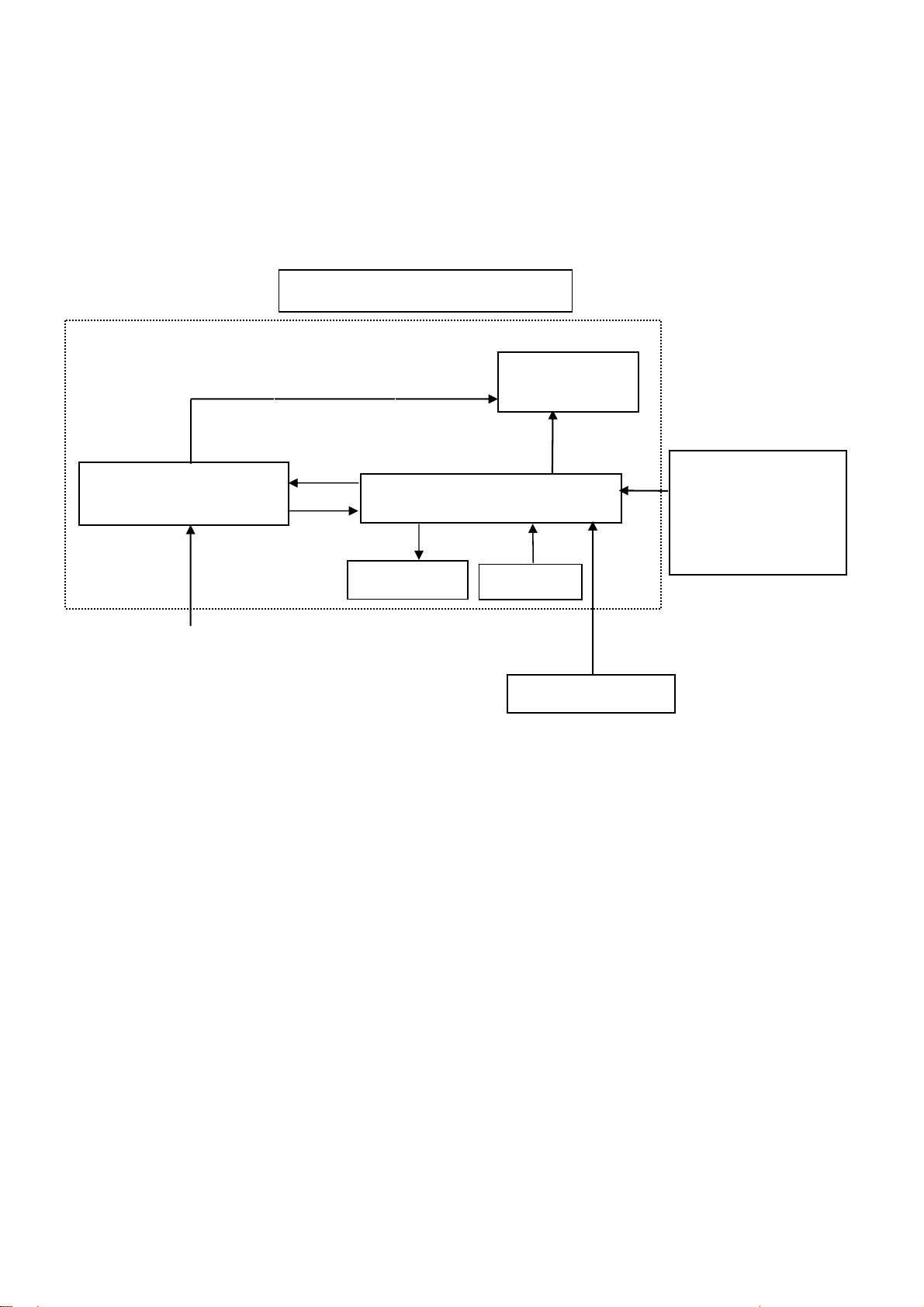
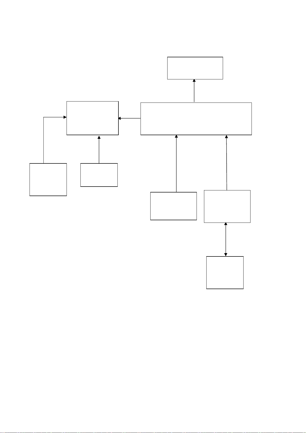
2. LCD MONITOR DESCRIPTION
The LCD MONITOR will contain a main board, a power board, a keypad board and an audio board which house the flat
panel control logic, brightness control logic and DDC.
The power board will provide AC to DC Inverter voltage to drive the backlight of panel and the main board chips each
voltage.
PWPC board
Include: adapter, inverter
AC-IN
100V-240V
Monitor Block Diagram
CCFL Drive.
Main Board
Audio board
Flat Panel and
CCFL backlight
Keyboard
RS232 Connector
For white balance
adjustment in factory
mode
Video signal,
HOST Computer
http://www.wjel.net
Page 5 of 55
Page 6
AOC LM923
3. OPERATING INSTRUCTIONS
3.1 GENERAL INSTRUCTIONS
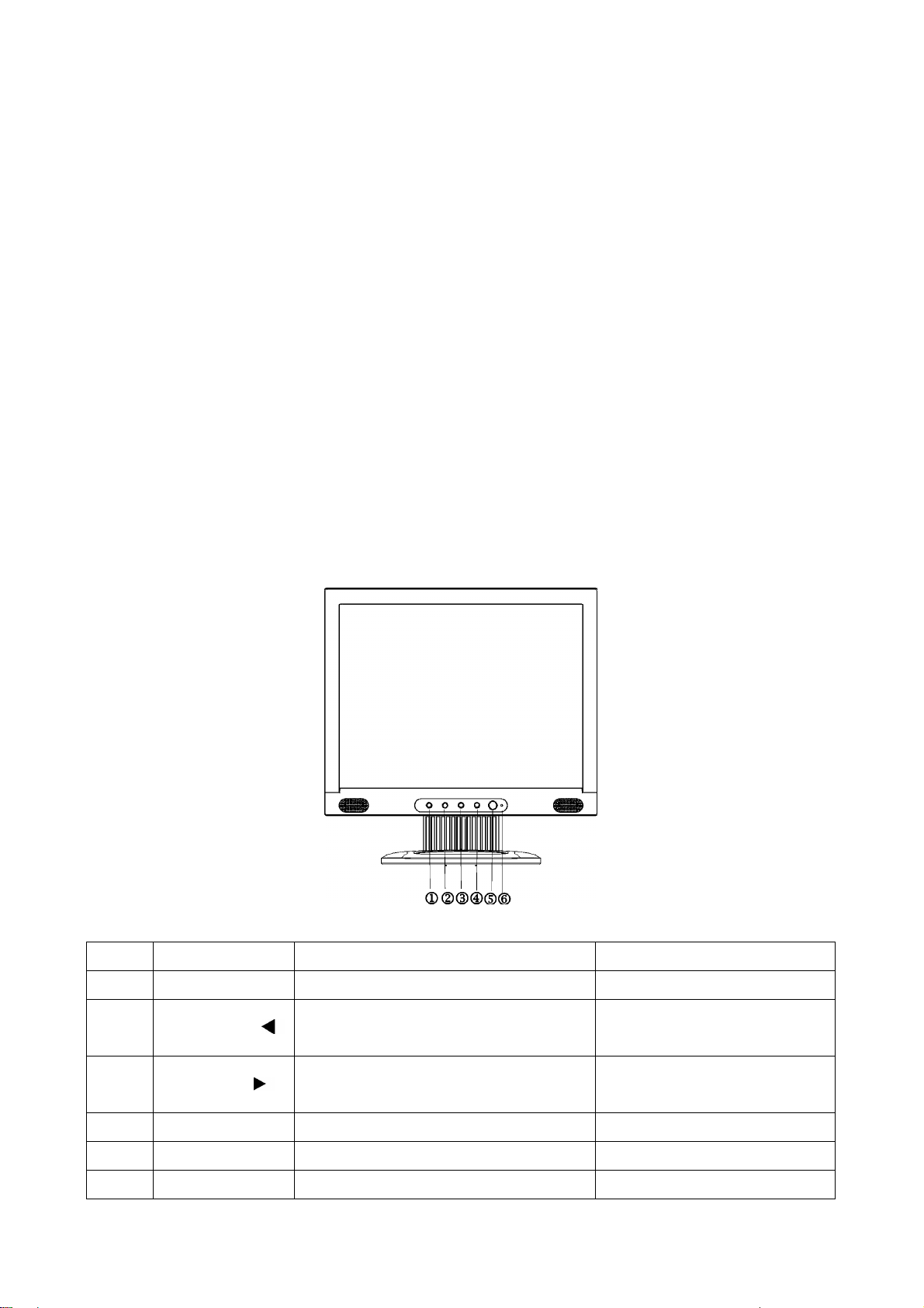
Press the power button to turn the monitor on or off. The other control buttons are located at front panel of the
monitor. By changing these settings, the picture can be adjusted to your personal preferences.
The power cord should be connected.
-
Connect the video cable from the monitor to the video card.
-
Press the power button to turn on the monitor, the power indicator will light up.
-
3.2 CONTROL BUTTONS
- Power Button:
When pressed, the monitor enters the off mode, and the LED turns blank. Press again to restore normal status.
- Left / Right Button:
The Left/Right Button is used to control the monitor functions. Press to switch functions or adjust settings.
- Auto Adjust Key:
The Auto Adjust Key is used to automatically set the H Position, V Position, Clock and Phase.
- Power Indicator:
Green — Power On mode.
Orange — Power Saving mode.
Blank —Power Off Mode.
O. Name
1 Auto/Exit Exit OSD or back to previous menu Auto configuration
2 Volume down/
3 Volume up /
4 MENU/ENTER Select Function or select Sub menu Activate OSD main menu
5 POWER Power On / Off Power On / Off
6 LED Green—On Orange—Save Green—On Orange—Save
http://www.wjel.net
1.Move the cursor to down
2.Decrease the value of the selected item
1.Move the cursor to up
2.Increase the value of the selected item
Within OSD
Page 6 of 55
Activate the volume menu
Activate the volume menu
Without OSD
Page 7
AOC LM923
3.3 ADJUSTING THE PICTURE
Adjustment steps:
1. Press the MENU-button to activate the OSD window.
2. Press < or > to select the desired function.
3. Press the MENU-button to select the function that you want to adjust.
4. Press < or > to change the settings of the current function.
5. To exit and save, select the exit function, or leave the monitor alone for 10 seconds. If you want to adjust any
other function, repeat steps 2-4.
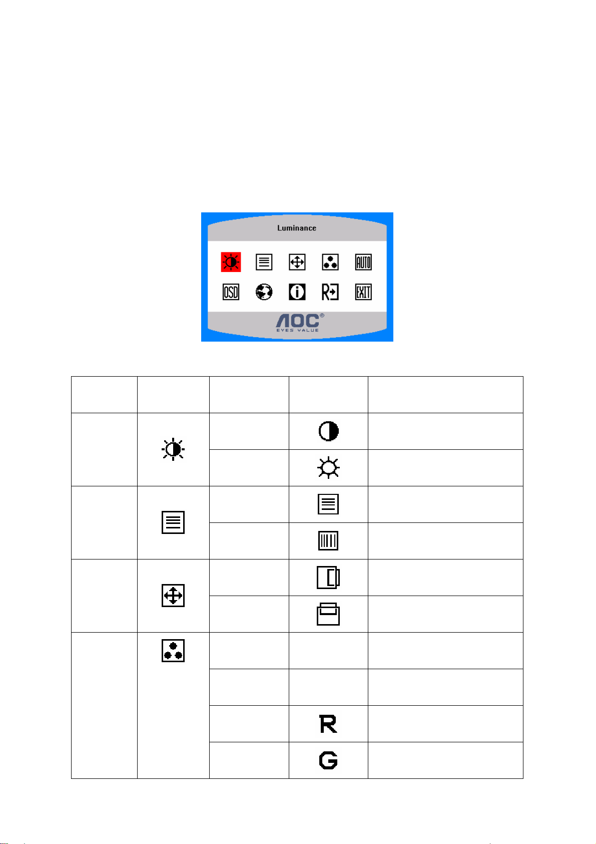
OSD TABLE:
Main Menu
Luminance
Image Setup
Image
Position
Item
Main Menu
Icon
http://www.wjel.net
Sub Menu Item Sub Menu Icon Description
Contrast
Brightness
Focus
Clock
H. Position
V. Position
Contrast from Digital-register.
Backlight Adjustment
Adjust Picture Phase to reduce
Horizontal-Line noise
Adjust picture Clock to reduce
Vertical-Line noise.
Adjust the horizontal position of
Adjust the vertical position of the
the picture.
picture.
Color Temp.
Warm N/A
Cool N/A
User / Red
User / Green
Page 7 of 55
Recall Warm Color Temperature
from EEPROM.
Recall Cool Color Temperature
from EEPROM.
Red Gain from Digital-register.
Green Gain Digital-register.
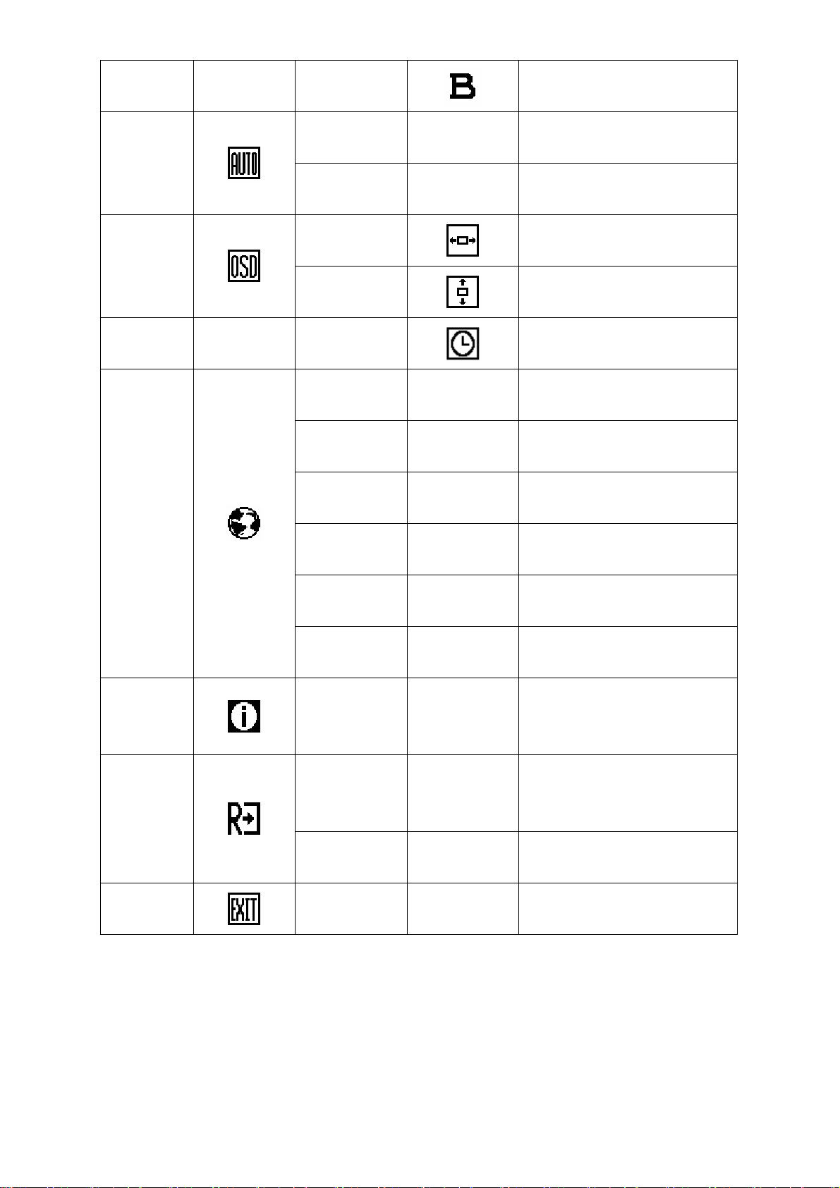
Page 8
AOC LM923
User / Blue
Auto Config
(Analog-Only
Model)
OSD Setup
OSD Timeout
Language
Yes
No N/A
H. Position
V. Position
English N/A
Deutsch N/A
Français N/A
Español N/A
N/A
Blue Gain from Digital-register.
Auto Adjust the H/V Position,
Focus and Clock of picture.
Do not execute Auto Config,
return to main menu.
Adjust the horizontal position of
the OSD.
Adjust the vertical position of the
OSD.
Adjust the OSD timeout.
Set OSD display language to
English.
Set OSD display language to
German.
Set OSD display language to
French.
Set OSD display language to
Spain.
Set OSD display language to
Italian.
Set OSD display language to
Simplified Chinese.
Show the resolution, H/V
frequency and input port of current
input timing.
Clear each old status of
Auto-configuration and set the
color temperature to Cool.
Do not execute reset, return to
main menu.
Information
Reset
Exit
Italiano N/A
简体中文
http://www.wjel.net
Information N/A
Yes N /A
No N/A
N/A N/A Exit OSD
N/A
Page 8 of 55
Page 9
4. INPUT/OUTPUT SPECIFICATION
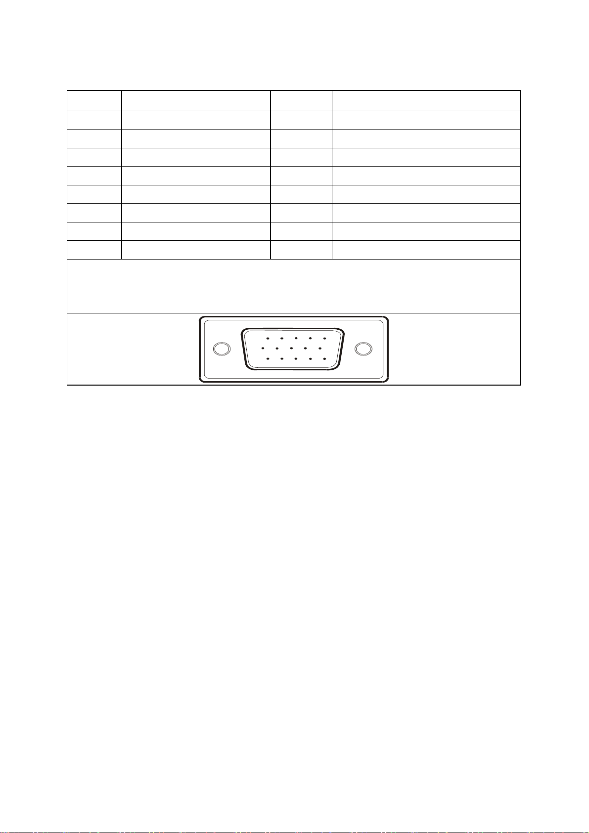
4.1 INPUT SIGNAL CONNECTOR
PIN NO. DESCRIPTION PIN NO. DESCRIPTION
1. Red Video 9. +5V
AOC LM923
2. Green Video 10.
3. Blue Video 11.
4. Ground 12. DDC-Serial Data
5. Ground 13. H-Sync
6. Red Ground 14. V-Sync
7. Green Ground 15. DDC-Serial Clock
8. Blue Ground
VGA connector layout
15
6
11 15
10
Detect Cable
NC
http://www.wjel.net
Page 9 of 55
Page 10
4.2 FACTORY PRESET DISPLAY MODES:
AOC LM923
STANDARD
Dos-mode 720 x 400 31.47kHz 70.0Hz
VGA
SVGA
XGA
SXGA
RESOLUTION
640 × 480 31.47kHz 60.0Hz
640 × 480 37.50kHz 75.0Hz
800 × 600 37.879kHz 60.0Hz
800 × 600 46.875kHz 75.0Hz
1024 × 768 48.363kHz 60.0Hz
1024 × 768 56.476kHz 70.0Hz
1024 × 768 60.021kHz 75.0Hz
1280 × 1024 64.000kHz 60.0Hz
1280 × 1024 80.000kHz 75.0Hz
4.3 POWER SUPPLY REQUIREMENTS
HORIZONTAL
FREQUENCY
VERTICAL
FREQUENCY
A/C Line voltage range 100 V ~ 240 V
A/C Line frequency range
Current 1.5A max at 100V; 0.8A max at 240 V
Peak surge current < 55A peak at 240 VAC and cold starting
Leakage current < 3.5mA
Power line surge
DC output Voltage
CURRENT
50 ± 3Hz, 60 ± 3Hz
No advance effects (no loss of information or defect)
with a maximum of 1 half-wave missing per second
5VDC ± 5%; 12VDC± 5%
1.5Amp (5V) ;2 Amp (12V)
http://www.wjel.net
Page 10 of 55
Page 11
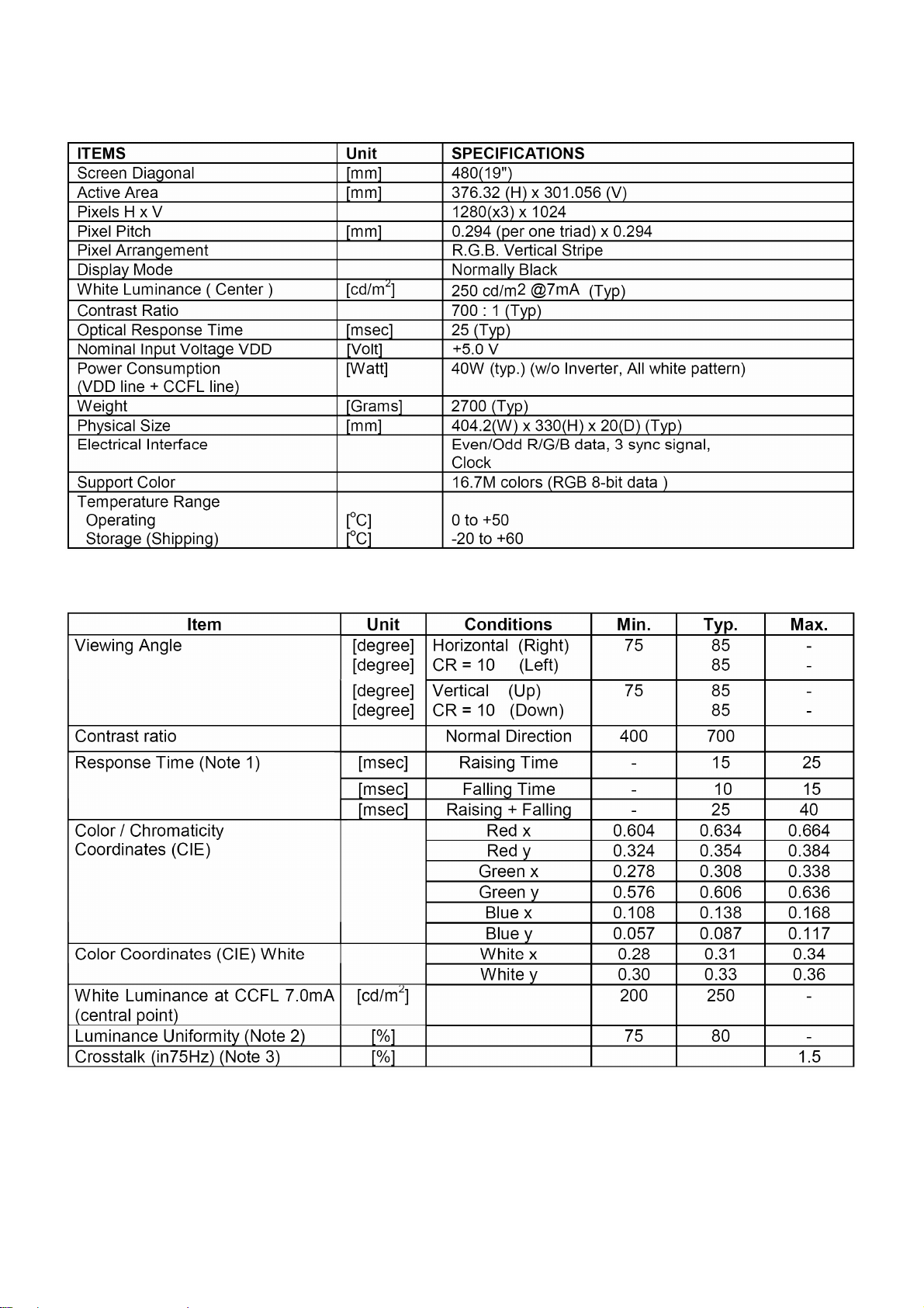
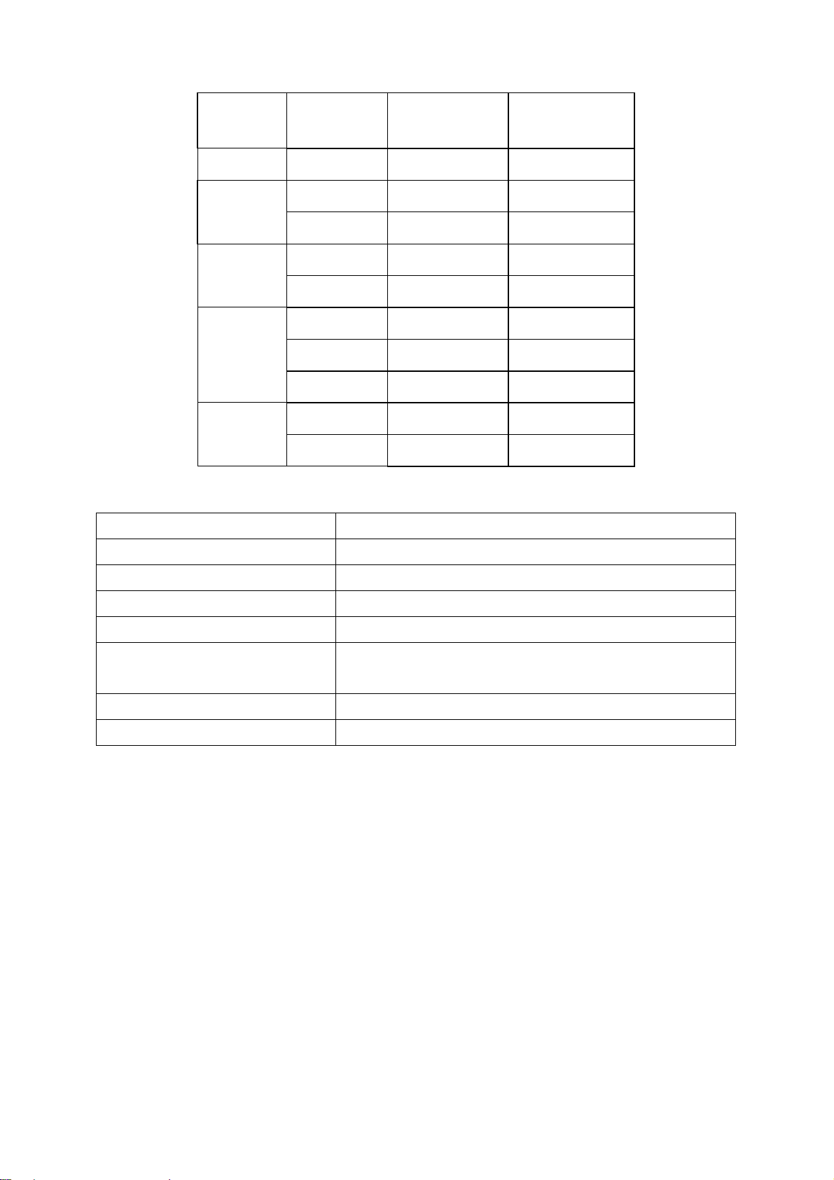
4.4 PANEL SPECIFICATION
4.4.1 Display Characteristics
AOC LM923
4.4.2 Optical Characteristics
http://www.wjel.net
Page 11 of 55
Page 12
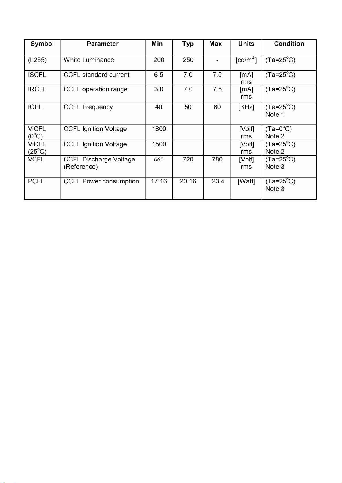
4.4.3 Parameter guide line for CCFL Inverter
AOC LM923
http://www.wjel.net
Page 12 of 55
Page 13
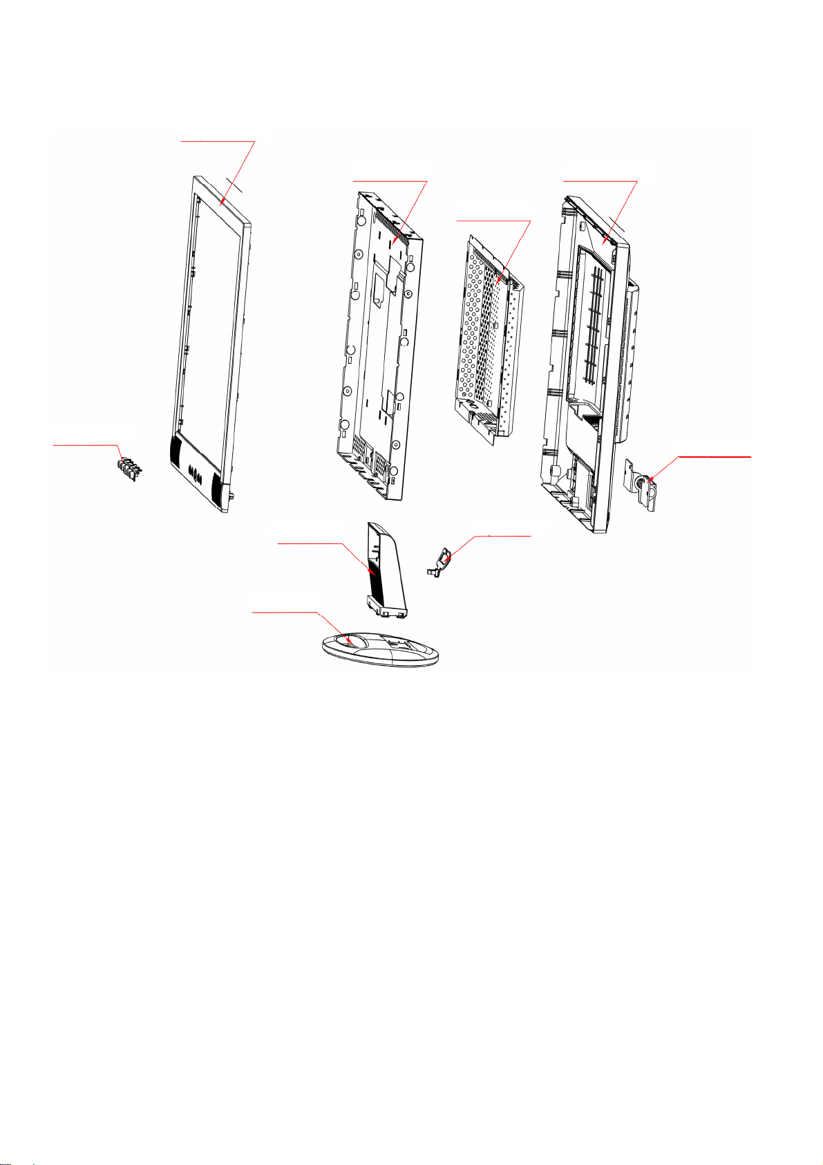
5. BLOCK DIAGRAM
5.1 MONITOR EXPLODED VIEW
bezel 34G1275AKG-3B
AOC LM923
Key pad 33G4713 AS L
stand 34G1273-GM-B
main frame 15G6093 AU
rear cover 34G1276-GM -4B
shield 85G6081-5
hinge ass’y 37G 490 1
clamp 33G4695 -1-C
base 34G1277-GM-B
http://www.wjel.net
Page 13 of 55
Page 14
5.2 SOFTWARE FLOW CHART
AOC LM923
1
2
N
4
5
Y
6
7
Y
N
N
3
9
10
Y
N
http://www.wjel.net
18
N
12
Y
14
19
N
11
13
15
17
N
Y
N
Y
16
Y
Page 14 of 55
Page 15

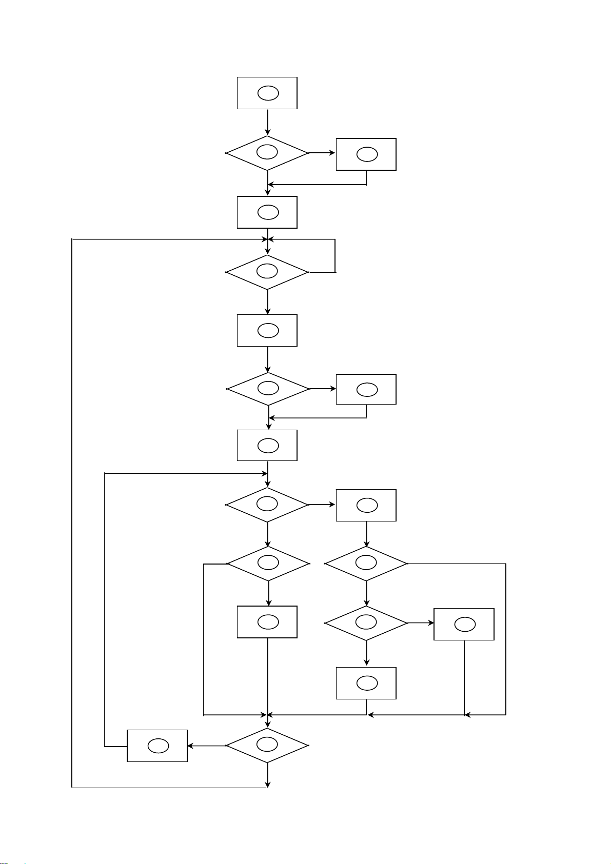
1) MCU initialize.
2) Is the EPROM blank?
3) Program the EPROM by default values.
4) Get the PWM value of brightness from EPROM.
5) Is the power key pressed?
6) Clear all global flags.
7) Are the AUTO and SELECT keys pressed?
8) Enter factory mode.
9) Save the power key status into EPROM.
Turn on the LED and set it to green color.
Scalar initializes.
10) In standby mode?
11) Update the lifetime of back light.
12) Check the analog port, are there any signals coming?
AOC LM923
13) Does the scalar send out an interrupt request?
14) Wake up the scalar.
15) Are there any signals coming from analog port?
16) Display "No connection Check Signal Cable" message. And go into standby mode after the message
disappear.
17) Program the scalar to be able to show the coming mode.
18) Process the OSD display.
19) Read the keyboard. Is the power key pressed?
http://www.wjel.net
Page 15 of 55
Page 16
5.3 ELECTRICAL BLOCK DIAGRAM
_
5.3.1 Main Board
AOC LM923
EPR_SDA
EPR_SCL
EEPROM
AT24C16N
(U602)
W78E65
MCU
(U601)
Key Board
Control
Crystal
14.318MHZ
(X401)
LCD Interface
(CN503)
Scalar IC MST8111B
(Include ADC, OSD)
(U401)
D-Sub
Connector
(CN301)
H sync
V sync
RGB
DB15_SDA,
DB15
EEPROM
24C02
(U301)
SCL
http://www.wjel.net
Page 16 of 55
Page 17
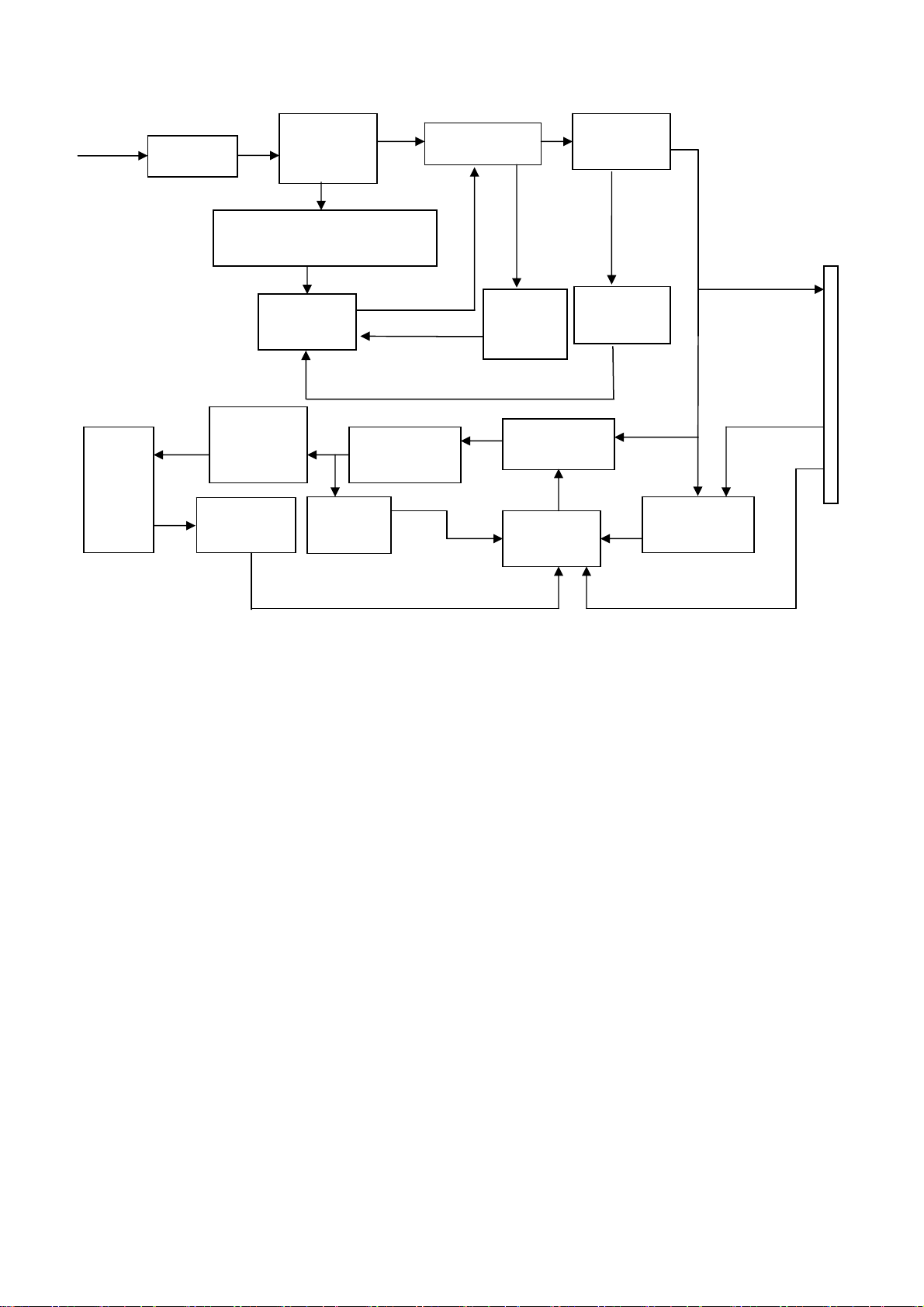
5.3.2 Inverter/Power Board
AC input
EMI filter
Bridge
Rectifier
and Filter
AOC LM923
Rectifier
Transformer
diode
Start Circuit: R906、 R907
CN902
12V
PWM
Control IC
Over
Voltage
Protect
Feedback
Circuit
Lamp
OSC and
Output
Circuit
Feedback
Circuit
Over
Voltage
DC Convert
Circuit
MOSFET
PWM
Control IC
ON/OFF
Control
DIM
DIM
http://www.wjel.net
Page 17 of 55
Page 18
6. SCHEMATIC
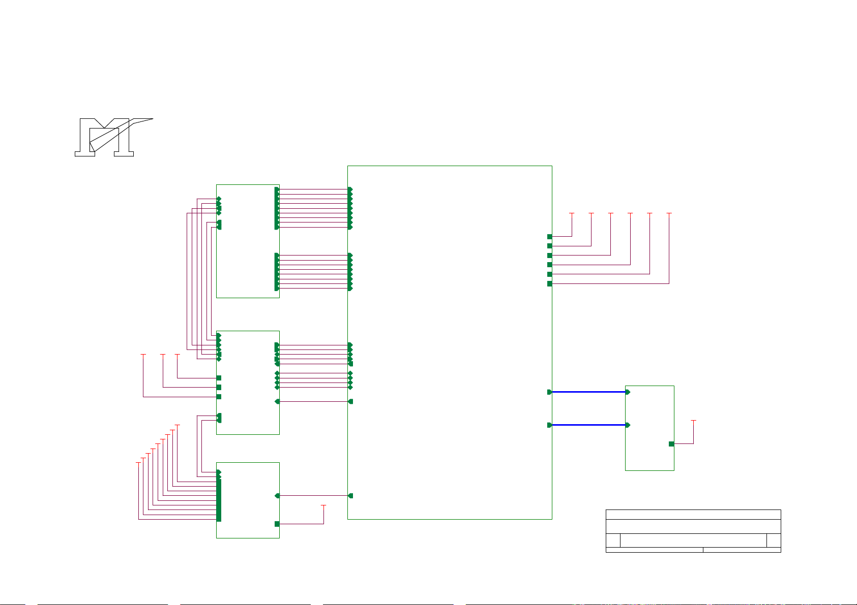
6.1 MAIN BOARD
715L1237-1
AOC LM923
MST 8011/8111 SCHEMATIC
B2
VAA4
VCC5V
VAA3
VAA2
VCC12V
VCC3.3
VCC2.5
VAA1
VCC12V
VCC5VVCPU
VCPU
B1
TXD
RXD
DDC_DAT
ST_DET1 HSYNC
ST_DET2
3.INPUT
B3
ST_DET2
ST_DET1
DDC_CLK
DDC_DAT
RXD
HWRESET
TXD
VCC5V
VCC12V
VCPU
onPANEL_5V/3.3V
onBACKLITE
6.MCU
B4
onBACKLITE
onPanel_5V/3.3V
VCPU
VCC12V
VCC3.3
AdjBACKLITE
VCC2.5
VAA1
VAA2
VAA3
VAA4
VCC5V
2.POWER
GNDR
GNDG
SOGDDC_CLK
GNDB
VSYNC
CLK+
CLK-
AD1
AD3
Volume
CSZ
SCL
SDA
AD0
AD2
RIN
GIN
BIN
R+
R-
G+
G-
B+
B-
INT
RIN
GNDR
GIN
GNDG
SOG
BIN
GNDB
HSYNC
VSYNC
R+
R-
G+
GB+
B-
CLK+
CLK-
CSZ
SCL
SDA
HWRESET
INT
AD0
AD1
AD2
AD3
Volume
VCC2.5
VCC3.3
VAA1
VAA2
VAA3
VAA4
PA[0..9]
PB[0..9]
VCC3.3VCC2.5
PA[0..9]
PB[0..9]
VAA1
VAA2
B5
PA[0..9]
PB[0..9]
VAA3
VAA4
VLCD
VLCD
5.PANEL INTERFACE
http://www.wjel.net
VLCD
VLCD
AdjBACKLITE
4.SCALER
Title
Size Document Number Rev
B
Date: Sheet
MST 8011/8111 FOR AOC
TOP
D
of
16Wednesday, November 10, 2004
Page 18 of 55
Page 19

AOC LM923
VCC5V
GND
VCC12V
GND
VCC5V
GND
VCC12V
C205
0.1uF
VCC12V 6
VCC5V+
VCC5V
VCC5V 3,4,6
VCPU
VCPU 6
C201
0.1uF
CN201
ON_OFFGND
2
1
3
5
7
9
11
CONN
VCC5V
4
6
8
10
12
R203
1K 1/16W
DIM
VCC12V
GND
VCC5V
GND
C202
220uF/25V
+
C203
0.1uF
R201 4.7K 1/16W
D201 SS14
FB201
600 OHM
C204
+
220uF/25V
R202
10K 1/16W
32
Q201
PMBS3904
R212 4.7K 1/16W
1
C
BE
onBACKLITE 6
Brightness
R204
10K 1/16W
PMBS3904
C206
1uF/25V
VCC5V+
AdjBACKLITE4
R205 4.7K 1/16W
32
Q202
1
C
BE
C214
0.1uF
VCC5V+
GS1D
C210
0.1uF
TO-263
U202
AIC1084-33M
3
VIN
1
ADJ
D202
VOUT
SOT-252
U201
RT9164
3 2
VI VO
2
C215
47uF/16V
VCC2.5
VCC2.5 4
+
C211
GND
1
47uF/16V
+
C216
0.1uF
C212
0.1uF
VCC3.3
VCC3.3 4
VAA1
VAA1 4
VAA2
VAA2 4
VAA3
VAA3 4
VAA4
VAA4 4
NEW
Circuit
VCC5V
R214 delete
R206
10K 1/16W
R216
4.7K 1/16W
onPanel_5V/3.3V6
R207
4.7K 1/16W
VCC5V
R208
10K 1/16W
R215
32
1
http://www.wjel.net
C207
0.1uF
Q204
PMBS3904
100K 1/16W
C217
0.068uF
VLCD
Q203
AO3401
+
C208
100uF/16V
VLCD 5
VCC5V VCC3.3
R209
0 1/16W
R211
10K 1/16W
R210
NC
VCC12V
R213
NC
Title
Size Document Number Rev
Date: Sheet
MST 8011/8111 FOR AOC
B
POWER
Page 19 of 55
26Wednesday, November 10, 2004
D
of
Page 20

D323
D322
TZMC5V6-GS08
TZMC5V6-GS08
AOC LM923
CN301
DB15
11
12
13
14
15
1
6
2
7
3
8
4
9
PC5V
5
VGA_CON
10
HSI
VSI
RXD 6
TXD 6
3
2
FB304 150 OHM
R312 100 1 /16W
D301
BAV99
1
3
2
D302
BAV99
1
FB301 0 1/1 6W
FB302 0 1/1 6W
FB303 0 1/1 6W
3
D303
BAV99
1
2
75 1/16W
VCC5V
R325
C301
NC
R301 100 1 /16W
R302 100 1 /16W
R303 100 1 /16W
C302
R326
NC
75 1/ 16W
C303
R327
NC
75 1/ 16W
R304 470 1 /16W
R305 100 1 /16W
R306 100 1 /16W
R307 100 1 /16W
VCC5V
R308
10K 1/16W
R309 100 1 /16W
R310 1K 1/1 6W
R311 1K 1/1 6W
C304 0.047uF
C305 0.047uF
C306 0.047uF
C307 0.001uF
C308 0.047uF
C309 0.047uF
C310 0.047uF
RIN 4
GIN 4
BIN 4
SOG 4
GNDR 4
GNDG 4
GNDB 4
ST_DET1 6
HSYNC 4
VSYNC 4
VCC5V
3
PC5V
2
D304
BAV70
CN302
RGB GND
HSYNC
VSYNC
SYNC GND
DDC SCL
DDC SDA
1/3shield
2/4shield
0/5shield
clk shield
DAT0+
DAT0-
DAT1+
DAT1-
DAT2+
DAT2-
DAT3+
DAT3-
DAT4+
DAT4-
DAT5+
DAT5-
JACK
D319
TZMC5V6-GS08
25
R
26
G
27
B
29
28
8
15
6
7
14
+5V
16
HPD
11
3
19
22
18
17
10
9
2
1
13
12
5
4
21
20
23
clk+
24
clk-
VCC5V
D320
TZMC5V6-GS08
D321
TZMC5V6-GS08
CLK_DDC2
DAT_DDC2
3
2
D306
BAV99
1
3
2
D318
TZMC5V6-GS08
D314
LL5232B 5.6V 5%
3
D307
BAV99
2
1
R319 100 1 /16W
R320 100 1 /16W
D315
LL5232B 5.6V 5%
D308
BAV99
3
D309
BAV99
R313
2.2K 1/16W
CLK_DDC
DAT_DDC
D316
LL5232B 5.6V 5%
3
D310
BAV99
C311
33pF
R314
10K 1/16W
DVI5V
C314
0.1uF
3
D311
BAV99
R321
10K 1/16W
C312
220pF
R322 100 1 /16W
3
D312
BAV99
3
D313
BAV99
D317
TZMC5V6-GS08
ST_DET2 6
B+ 4
B- 4
G+ 4
G- 4
R+ 4
R- 4
CLK+ 4
CLK- 4
R315 100 1 /16W
R316 100 1 /16W
DDC_DAT6
DDC_CLK6
R317
10K 1/16W
R323
10K 1/16W
R318
10K 1/16W
VCC5V
R324
10K 1/16W
1
U301
8
VCC
7
WP
6
SCL
M24C02WMN6
DVI5V
2
3
D305
BAV70
1
U302
8
VCC
7
WP
6
SCL
M24C02WMN6
1
A0
2
A1
3
A2
45
GNDSDA
1
A0
2
A1
3
A2
45
GNDSDA
http://www.wjel.net
1
1
2
1
2
2
1
2
1
1
2
Title
Size Document Number Rev
B
Date: Sheet
MST 8011/8111 FOR AOC
INPUT
36Wednesday, November 10, 2004
C313
0.1uF
C315
0.1uF
D
of
Page 20 of 55
Page 21

VDVI
RIN3
GNDR3
GIN3
GNDG3
SOG3
BIN3
GNDB3
HSYNC3
VSYNC3
R+3
R-3
G+3
G-3
B+3
B-3
CLK+3
CLK-3
R403 390 1/16W
CSZ6
SCL6
SDA6
HWRESET6
AdjBACKLITE2
Volume6
C402 22pF
14.318MHz
C403 22pF
C404 0.1uF
AOC LM923
VCC3.3
FB401
VPO VCC2.5
VCC3.32
VAD
VDVI
VPLL
55
35
45351
65
U401
AVDD
AVDD
63
RIN0
62
RIN0M
60
GIN0
59
GIN0M
61
SOGIN0
58
BIN0
57
BIN0M
37
HSYNC0
38
VSYNC0
29
DDC1_CLK/GPO8
28
DDC1_DAT/GPO7
40
R+
41
R-
43
G+
44
G-
46
B+
47
B-
49
CK+
50
CK-
52
66
67
69
71
70
32
72
73
74
33
34
REXT
REFP
REFM
CSZ
SCL
SDA
HWRESETZ
INT
PWM0
PWM1
XIN
XOUT
BYPASS
AVSS_LPLL
AVSS
56
68
C401
0.1uF
INT6
X401
AVSS
64
AVDD_MPLL
AVSS
36254
AVDD_DVI
AVDD_DVI
MST8111B
AVSS_PLL
AVSS_MPLL
VDPLL
11218494104
53
VDDP
AVDD_PLL
AVSS_DVI
AVSS_DVI
AVSS_DVI
39
4210208595
48
VPO
VDDP
VDDP
VDDP
GNDP
GNDP
114
VDDP
GNDP
VDD
126188797117
PA0
VDDP
VDDP
VDDC
VDDC
VDDC
NC/LVB3P
NC/LVB3M
NC/LVBCKP
NC/LVBCKM
NC/LVB2P
NC/LVB2M
NC/LVB1P
NC/LVB1M
NC/LVB0P
NC/LVB0M
BUS TYPE/NC
http://www.wjel.net
GNDP
GNDP
GNDP
GNDC
GNDP
115
1271986
105
VDDC
LVA3P
LVA3M
LVACKP
LVACKM
LVA2P
LVA2M
LVA1P
LVA1M
LVA0P
LVA0M
ADO/NC
AD1/NC
AD2/NC
AD3/NC
GNDC
GNDC
96
116
GNDC
102
PA1
103
PA2
106
PA3
107
PA4
108
PA5
109
PA6
110
PA7
111
PA8
112
PA9
113
PB0
118
PB1
119
PB2
120
PB3
121
PB4
122
PB5
123
PB6
124
PB7
125
PB8
128
PB9
1
VCC5V
R407
10K 1/16W
30
77
78
31
6
R405
10K 1/16W
10K 1/16W
Direct Bus
3-WIRE
R404
R406
10K 1/16W
R401
NC
4.7K
PA[0..9]
PB[0..9]
600 OHM
C405
10uF/16V
AD0 6
AD1 6
AD2 6
AD3 6
R402
4.7K
NC
+
C406
0.1uF
PA[0..9] 5
PB[0..9] 5
VCC3.3
C407
C408
0.1uF
0.1uF
R402
100 1/16W
R401
NC
C409
0.1uF
C410
0.1uF
C411
0.1uF
C412
C413
0.1uF
0.1uF
Title
Size Document Number Rev
B
Date: Sheet
VCC2.52
VAA1
VAA12
VAA2
VAA22
VAA3
VAA32
VAA4
VAA42
MST 8011/8111 FOR AOC
SCALER
FB402
600 OHM
C414
10uF/16V
FB403
600 OHM
10uF/16V
FB404
600 OHM
10uF/16V
FB405
600 OHM
10uF/16V
FB406
600 OHM
10uF/16V
C419
C422
C424
C427
VDD
+
VAD
VPLL
VDVI
VDPLL
46Wednesday, November 10, 2004
+
+
+
+
C415
0.1uF
C420
0.1uF
C423
0.1uF
C425
0.1uF
C428
0.1uF
of
C416
0.1uF
C421
0.1uF
C426
0.1uF
C417
0.1uF
C418
0.1uF
D
Page 21 of 55
Page 22

AOC LM923
PA[0..9]4
PB[0..9]4
PA[0..9]
PB[0..9]
PA0
PA1
PA2
PA3
PA4
PA5
PA6
PA7
PA8
PA9
PB0
PB1
PB2
PB3
LVA3P
LVA3M
LVACKP
LVACKM
LVA2P
LVA2M
LVA1P
LVA1M
LVA0P
LVA0M
LVB3P
LVB3M
LVBCKP
LVBCKM
LVB0M
LVB1M
LVB2M
LVBCKM
LVB3M
LVA0M
LVA1M
LVA2M
LVACKM
LVA3M
RXO0RXO1RXO2RXOCRXO3RXE0RXE1RXE2RXECRXE3-
1
3
5
7
9
11
13
15
17
19
21
23
CN503
2
4
6
8
10
12
14
16
18
20
22
24
RXO0+
RXO1+
RXO2+
RXOC+
RXO3+
RXE0+
RXE1+
RXE2+
RXEC+
RXE3+
LVB0P
LVB1P
LVB2P
LVBCKP
LVB3P
LVA0P
LVA1P
LVA2P
LVACKP
LVA3P
PB4
PB5
PB6
PB7
PB8
PB9
LVB2P
LVB2M
LVB1P
LVB1M
LVB0P
LVB0M
C509
+
47uF/16V
Title
CONN
C510
0.1uF
VLCD
VLCD 2
C511
0.1uF
MST 8011/8111 FOR AOC
http://www.wjel.net
Size Document Number Rev
A
Date: Sheet
PANEL INTERFACE
56Wednesday, November 10, 2004
R502
0 1/16W
of
D
Page 22 of 55
Page 23

OUT-L+
OUT-L-
AOC LM923
VCPU
VCPU2
876
876
VSS VCC
22 44
P0.0
P0.1
P0.2
P0.3
P0.4
P0.5
P0.6
P0.7
P2.0
P2.1
P2.2
P2.3
P2.4
P2.5
P2.6
P2.7
T0/P3.4
T1/P3.5
P3.6/WR
P3.7/RD
P3.1/TXD
P3.0/RXD
C614
NC
CN602
1
3
5
7
9
11
13
15
CONN
RN601
10K 1/16W
43
42
41
40
39
38
37
36
24
25
26
27
28
29
30
31
16
17
18
19
13
11
DVI-DSUB SELECT
Mute_key
C615
NC
2
4
6
8
10
12
14
16
123
LED_BLUE
LED_ORANGE
R602
10K 1/16W
U601
35
EA/VP
21
XTAL1
20
XTAL2
10
RESET
12
P4.3
14
INT0/P3.2
15
INT1/P3.3
33
ALE/P
32
PSEN
2
P1.0
3
P1.1
4
P1.2
5
P1.3
6
P1.4
7
P1.5
8
P1.6
9
P1.7
W78E65P-40
VCPU
R631
NC
NC
DVI-DSUB SELECT
LED_GRN
C610
OUT-L+
OUT-L-
0.001uF
C601
0.1uF
R630 NC
R633 NC
R601
10K 1/16W
C602 22pF
X601
+
C603
20MHz
VCPU
U603 MAX810STR
23
RSTVCC
GND
1
Reset
Circuit
C605
0.22uF
CN601
CONN
FB603
2
4
6
8
10
12
14
600 OHM
OUT-R+
OUT-R-
1
3
5
7
9
11
13
U602
1
A0
2
A1
3
A2
4 5
GND SDA
AT24C16N-10SC-2.7
FB601 600 OHM
FB602 600 OHM
C613
0.1uF
C617
100pF
VCPU
8
VCC
7
WP
6
SCL
VCC12V
VCC5V
R627 10K 1/16W
R626 10K 1/16W
C612
0.1uF
R625 10K 1/16W
C611
1uF/25V
VCC12V 2
VCC5V 2,3,4
VCC5V
R640
NC
D601
LL4148-GS08
R638 NC
VCC5V
32
10uF/16V
C604 22pF
R603
10K 1/16W
R604 10K 1/16W
R605 10K 1/16W
R639 100 1/16W
ST_DET13
ST_DET23
R643
NC
Q604
NC
1
R641 NC
R642 0 1/16W
LED_G
AUTO
R620 470 1/16W
R622 470 1/16W
RIGHT
POWER
R624 470 1/16W
http://www.wjel.net
INT4
R608 100 1/16W
R609 100 1/16W
R615 10K 1/16W
R614 10K 1/16W
Standby
Mute
R616
1
4.7K 1/16W
C606
0.001uF
Volume 4
VCPU
R617
120 1/16W
Q601
PMBS3906
3 2
C608
0.001uF
R632
5
5
RN602
10K 1/16W
123
4
4
R606 10K 1/16W
R607 10K 1/16W
R610 NC
R611 NC
R634 100 1/16W
R635 100 1/16W
VCPU
Mute_key
OUT-R+
OUT-R-
CN603
1
1
2
2
3
3
4
4
NC
R637 470 1/16W
POWER
ENTER
RIGHT
LEFT
AUTO
LED_B
LED_O
LED_G
C616
1uF/25V
R636 0 1/16W
R613
R612
10K 1/16W
NC
VCPU
R628
0 1/16W
Q603
PMBS3906
3 2
C607
0.001uF
C618
0.1uF
R629
1
4.7K 1/16W
R621 470 1/16W
R623 470 1/16W
C609
0.001uF
HWRESET 4
onPANEL_5V/3.3V 2
onBACKLITE 2
CSZ 4
SCL 4
SDA 4
VCPU
AD0 4
AD1 4
AD2 4
AD3 4
DDC_DAT 3
DDC_CLK 3
TXD 3
RXD 3
VCPU
R618
120 1/16W
LED_B
ENTER
LEFT
Title
Size Document Number Rev
B
Date: Sheet
Q602
PMBS3906
3 2
1
R619
4.7K 1/16W
LED_O
MST 8011/8111 FOR AOC
MPU
66Wednesday, November 10, 2004
of
D
Page 23 of 55
Page 24

6.2 AUDIO BOARD
715L1279-A
2003/10/31 ADD NEW EMI SOULATION L113 L114
L108
600 OHM
71L59B121
71L59B121
120 OHM
VOLUME
DGND
RIN-
LIN-
CGND GND
WHEN SELECT TDA6110A2, PLEASE CONNECT VR101,VR102,VR103,R125,R126, PIN8,9,10,11 FOR
TDA3002D2,
WHEN SELECT TDA3003D2, PLEASE CONNECT R110,R111,R112,R113, PIN8,9,10,11 FOR
TDA3003D2,3W
WHEN PIN9 SELECT GND, VOLUME =VARMAX-VARDIFF =16DB
WHEN PIN10 SELECT+5V
AOC LM923
C125
C126
ROUT+
C142
1000P
12
L104
600 OHM
GND
+12V
C122
ROUTP
PGNGR
PGNGL
LOUTP
C114
GND
12
C118
1000P/1nf
C139
ROUTP
MODE_OUT/NC
LOUTP
0.1uF
GND
C123
0.01uF/10nf
2003.09.18 EMI ADD SOLUTION FOR L110 L111 CANCEL L101-104
3738394041424344454647
BSRP
PVCCR
PVCCR
36
VCLAMPR
35
34
MUTE
33
AVcc
32
VAROUTR/NC
31
VAROUTL/NC
30
AGND
29
AVdd
28
COSC
27
ROSC
26
AGND
25
VCLAMPL
PVCCL
PVCCL
BSLP
24
C115
0.01uF/10nf
+12V
L101
600 OHM
C141
C140
0.1uF
0.1uF
GND
ROUT-
ROUT+
LOUT-
LOUT+
C105
+
GND
1.0uF
+12V
C103
0.1uF/100nf
AVDD
C102 0.1uF/100nf
C101 220 pF
R107 120K
+
C106
1.0uF
GND
WHEN SELECT TDA6110A2, PLEASE CONNECT R123, PIN31,32,35, DELETE R101, FOR
TDA3002D2,9W
CONN
DGND
CGND
CN102
4
3
2
1
WAFER 4P2.0 R/A
R101
+
C104
NC/0K
10uF
GND
GND
2003.09.18 EMI ADD SOLUTION FOR L110 L111 CANCEL L101-104
LOUT+
C146 0.1uF
GND
/SHUTDOWN
LOUT+
LOUT-
MUTE
C150
NC/470P
GND
CN104
1
2
3
4
5
6
7
PHONE_RIGHT
PHONE_LEFT
MODE
R123
NC/0K
MUTE
+
C131 1.0uF
R114
10K
+
C132 1.0uF
R115
10K
2003/10/31 ADD NEW EMI SOULATION C127,C142
GND
GND
C144
C145
0.1uF
0.1uF
CN101
2
4
6
8
10
12
14
WAFER 2*7P 2.54mm
C149
NC/470P
GND
2003/07/18 э
CN101 PIN 5 GND, PIN6
/SHUTDOWN,PIN7
VOLUME,PIN8 MUTE
MODE
R117 10K
R116
10K
GND
1
3
5
7
9
11
13
C135
0.47uF
C143
0.1uF
GND
+
AVDD
R121
10K
R120
10K
600 OHM
L109
GND
R122
120K
CN103A
4
3
2
1
WAFER 4P2.0 R/A
PHONE_RIGHT
PHONE_LEFT
AGND
C134
220uF/16V
U203
1
BYP
2
GND
3
SD
4 5
IN2 VO2
TPA6110A2DGNR
R118
10K
C148
C147
NC/470P
NC/470P
GND
GND
VDD
+
IN1
VO1
VOLUME
L105
600 OHM
ROUT+
ROUT-
DELETE
J101
3
4
2
1
NC
C133
+
220uF/16V
R119
10K
8
7
AVDD
6
+12V
+
C128
C130
470uF/16V
0.1uF
GND
L107
600 OHM
L114
/SHUTDOWN
L113
120 OHM
R127
NC/4.7K
ROUT-
1000P/1nf
1000P/1nf
C117,118,125,126,127,142 1000PF FOR EMI 0905
600 OHM
+12V
C152
0.1uF
C120
0.01uF/10nf
VCC
R102
NC/0K
R106
0K
RIN+
R108
DGND
NC
LIN+
R109
NC
R110
1K
+
C136
1.0uF
R125 0K
R126 0K
R130
4.7K
C107 1.0uF
C108 1.0uF
C109 1.0uF
C110 1.0uF
C111 1.0uF
10K/4.7K
R129
R112
0K
LOUT-
48
U101
R103
BSRN
120K
1
/SD
2
+
RINN
3
+
RINP
4
+
V2P5
5
+
LINP
6
+
LINN
7
AVddREF
8
VREF
9
VARDIFF/AGND
10
VARMAX/AGND
11
VOLUME
12
REFGND
R113
6.8K /NC
BSLN
1314151617181920212223
C112
0.01uF/10nf
+12V
600 OHM
RIN-
LIN-
MODE
PHONE_RIGHT
http://www.wjel.net
PHONE_LEFT
C137-C138 100P FOR EMI 1104
L1/L118
PVCCR
PVCCL
C137
0.1uF/100nf
1000P/1nf
100P
0.1uF/100nf
ROUTN
LOUTN
C116
C117
GND
C124
10uF
C121
C151
0.1uF
10uF
L
3 4
+
0.1uF/100nf
PGNGR
ROUTN
TPA3002D2PHPR
LOUTN
PGNGL
C113
0.1uF/100nf
+
L2/L116
L
3 4
C127
1000P
C138
100P
GND
L103
PVCCR
PVCCL
L102
C117,118,125,126 パ0.001UF э 0.1UF FOR EMI 0905
GND
2003/07/18 э CN104 パ3 PIN 倒 7 PIN
+
C129
470uF/16V
715L1279-A
CIRCUIT
Title
2003/12/03
TI_TDA3003D2/TDA3002D2 3W/9W AUDIO
Size Document Number Rev
AOC 19"LCD MONITOR FOR NMV A
C
Date: Sheet
of
11Thursday, December 04, 2003
Page 24 of 55
Page 25

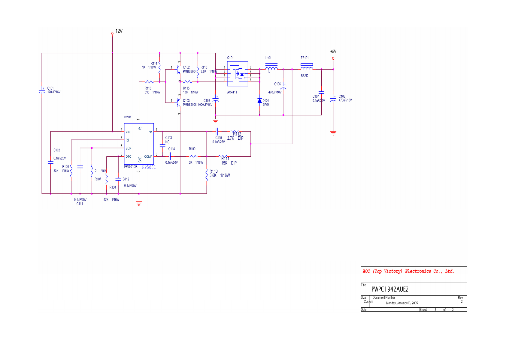
6.3 POWER BOARD
715G1142-4-AUE
AOC LM923
http://www.wjel.net
Page 25 of 55
Page 26

AOC LM923
http://www.wjel.net
Page 26 of 55
Page 27
AOC LM923
http://www.wjel.net
Page 27 of 55
Page 28

AOC LM923
7. PCB Layout
7.1 MAIN BOARD
715L1237-1
http://www.wjel.net
Page 28 of 55
Page 29
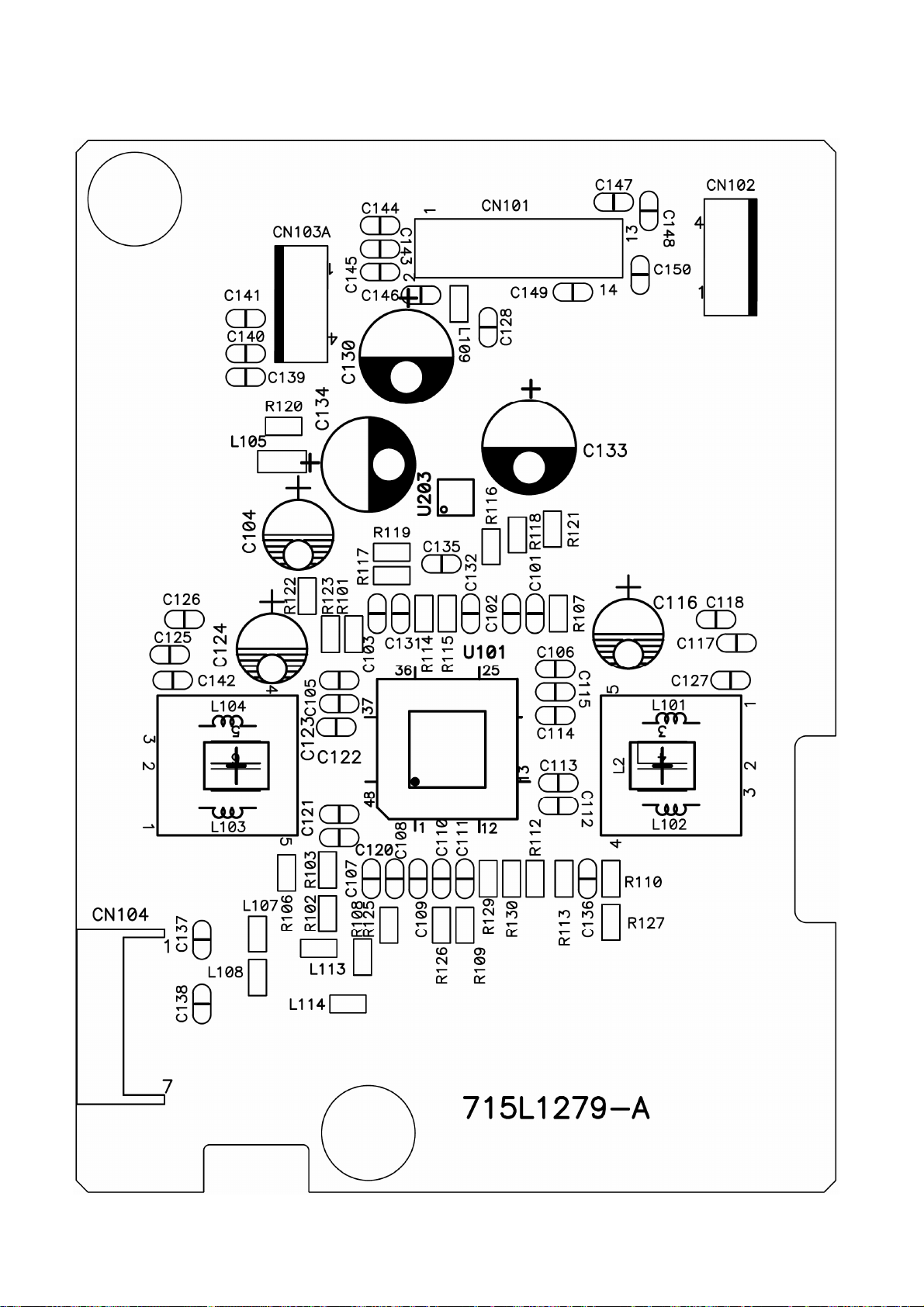
AOC LM923
7.2 AUDIO BOARD
715L1279- A
http://www.wjel.net
Page 29 of 55
Page 30
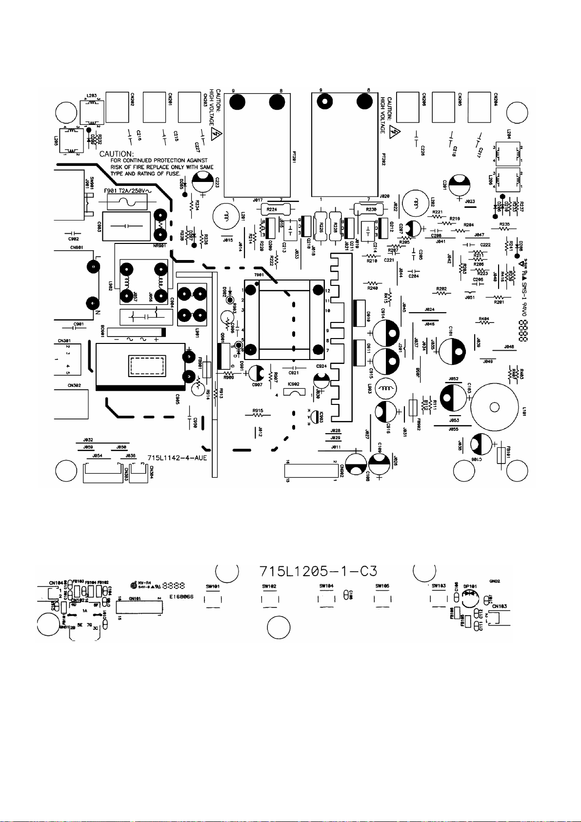
AOC LM923
7.3 POWER BOARD
715G1142-4AUE
7.4 KEY BOARD
715L1205-1-C3
http://www.wjel.net
Page 30 of 55
Page 31

AOC LM923
8. MAINTAINABILITY
8.1 EQUIPMENTS AND TOOLS REQUIREMENT
1. Voltmeter.
2. Oscilloscope.
3. Pattern Generator.
4. DDC Tool with an IBM Compatible Computer.
5. Alignment Tool.
6. LCD Color Analyzer.
7. Service Manual.
8. User Manual.
http://www.wjel.net
Page 31 of 55
Page 32

AOC LM923
8.2 TROUBLE SHOOTING
8.2.1 Main Board
No power
No power
Press power key and look
if the picture is normal
NG
Please reinsert and make sure
the AC of 100-240 is normal
OK
Measure U201 PIN2=2.5V
U202 PIN2=3.3V
NG
OK
NG
Reinsert or check the
Adapter/Inverter
section
Check CN201 or replace
U201, U202
X601 and X401 oscillate
waveforms are normal
OK
Replace U601
NG
NG
Replace X601, X401
http://www.wjel.net
Replace U401
Page 32 of 55
Page 33

AOC LM923
No picture (LED orange)
No picture
The button if
under control
OK
Measure U201 PIN2=2.5V
U202 PIN2=3.3V
NG
OK
NG
Replace
U201, U202
X601 oscillate
waveform is normal
OK
Check reset circuit of
U601 is normal
OK
Replace U601
NG
NG
Replace X601
Check Correspondent
component
X401 oscillate
waveform is normal
OK
NG
Replace X401
Check HS/VS from
Replace U401
CN301is normal
OK
NG
Replace U401
http://www.wjel.net
Check Correspondent
component
Page 33 of 55
Page 34

AOC LM923
White screen
White screen
Measure Q204 base
is low level?
NG
X601 oscillate
waveform is normal
OK
OK
NG
Replace X601
Check Q204 is broken or
CN503 solder?
Check reset circuit of
U601 is normal
NG
Check Correspondent
OK
component.
OK
NG
Check Correspondent
component.
Replace PANEL
Replace U601
http://www.wjel.net
Page 34 of 55
Page 35

AOC LM923
8.2.2 Power/Inverter Board
No power
Check CN902 pin2, 4 = 12V
NG
Check AC line volt 110V or 220V
OK
NG
Check the voltage of C905(+)
OK
NG
Check start voltage for the pin3 of IC901
OK
NG
Check AC input
Check bridge rectified circuit and F901 circut
Check R906,R907 and Change IC901
Check the auxiliary voltage is bigger than
10V and smaller than 20V
OK
NG
Check IC901 pin8 PWM wave
http://www.wjel.net
OK
NG
Check Q901, R914,T901,D910,D911,ZD902
1) Check IC901
2) Check ZD901,Q902, Q903…OVP circuit
Check IC901
Page 35 of 55
Page 36

AOC LM923
2.) W / LED, No Backlight
Check CN902 pin2, 4 = 12V
OK
Check ON/OFF signal
NG
Check adapter or Main Board
OK
NG
Check Main Board
Check U201 pin9=12V
OK
NG
Change Q201 or Q202
Check U201 PIN1 have the output of sawtooth wave at short time
NG
OK
Change U201
Check D201 (-)/ D202 (-) have the output of square wave at short time.
OK
NG
Check Q203/Q205/Q207/ D201
Check Q204/Q206/Q208/ D202
Check the resonant wave of pin2 & pin5 for PT201/PT202
Check the output of PT201/202
OK
http://www.wjel.net
NG
Check Q209/Q210/C213
Check Q211/Q212/C214
NG
OK
Change PT201/202
Check connecter & lamp
Page 36 of 55
Page 37

AOC LM923
8.2.3 Keypad Board
OSD is unstable or not working
Is Key Pad Board connecting normally?
Y
Is Button Switch normally?
Y
Is Key Pad Board normally?
Y
Check Main Board
N
Connect Key Pad Board
N
Replace Button Switch
N
Replace Key Pad Board
http://www.wjel.net
Page 37 of 55
Page 38

AOC LM923
9.WHITE-BALANCE, LUMINANCE ADJUSTMENT
Approximately 30 minutes should be allowed for warm up before proceeding White-Balance adjustment.
1. How to do the Chroma-7120 MEM. Channel setting
A. Reference to chroma 7120 user guide
B. Use “ SC” key and “ NEXT” key to modify XyY value and use “ID” key to modify the
TEXT description Following is the procedure to do white-balance adjust
2. Setting the color temp. you want
A. MEM.CHANNEL 3 (7800 color):
7800 color temp. parameter is x = 296 ±20, y = 311 ±20, Y = 180 cd/m
B. MEM.CHANNEL 4 (6500 color):
6500 color temp. parameter is x = 313±20, y = 329 ±20, Y = 180 cd/m2
3. Into factory mode of AOC LM923
Turn on power, press the MENU button, pull out the power cord, and then plug the power cord. Then the factory OSD
2 ,
will be at the left top of the panel.
4. Bias adjustment:
Set the Contrast
5. Gain adjustment:
Move cursor to “-F-” and press MENU key
A. Adjust C2 (7800) color-temperature
1. Switch the Chroma-7120 to RGB-Mode (with press “MODE” button)
2. Switch the MEM. Channel to Channel 3 (with up or down arrow on chroma 7120)
3. The LCD-indicator on chroma 7120 will show x = 296 ±20, y = 311 ±20, Y = 180 cd/m
4. Adjust the RED of color1 on factory window until chroma 7120 indicator reached the value R=100
5. Adjust the GREEN of color1 on factory window until chroma 7120 indicator reached the value G=100
6. Adjust the BLUE of color1 on factory window until chroma 7120 indicator reached the value B=100
7. Repeat above procedure (item 4,5,6) until chroma 7120 RGB value meet the tolerance =100±2
B. Adjust C1 (6500) color-temperature
1. Switch the chroma-7120 to RGB-Mode (with press “MODE” button)
to 50; Adjust the Brightness to 80.
2
http://www.wjel.net
2. Switch the MEM.channel to Channel 4(with up or down arrow on chroma 7120)
3. The LCD-indicator on chroma 7120 will show x = 313 ±20, y = 329 ±20, Y = 180 cd/m
4. Adjust the RED of color3 on factory window until chroma 7120 indicator reached the value R=100
5. Adjust the GREEN of color3 on factory window until chroma 7120 indicator reachedthe value G=100
6. Adjust the BLUE of color3 on factory window until chroma 7120 indicator reached the value B=100
7. Repeat above procedure (item 4,5,6) until chroma 7120 RGB value meet the tolerance =100±2
C. Turn the Power-button off to quit from factory mode.
Page 38 of 55
2
Page 39

AOC LM923
10. EDID CONTENT
00 01 02 03 04 05 06 07 08 09 10 11 12 13 14 15
0 00 FF FF FF FF FF FF 00 05 E3 23 A9 0B 95 0D 00
16: 19 0E 01 03 68 26 1E 78 2A 6D 65 A2 5A 4C 9D 23
32: 13 4F 54 BF EF 00 81 80 01 01 01 01 01 01 01 01
48: 01 01 01 01 01 01 30 2A 00 98 51 00 2A 40 30 70
64: 13 00 78 2D 11 00 00 1E 00 00 00 FF 00 31 32 33
80: 34 35 36 37 38 39 30 31 32 33 00 00 00 FD 00 37
96: 4B 1E 53 0E 00 0A 20 20 20 20 20 20 00 00 00 FC
112: 00 4C 4D 39 32 33 0A 20 20 20 20 20 20 20 00 24
http://www.wjel.net
Page 39 of 55
Page 40

AOC LM923
11. BOM LIST
T980KAXHLFMRA
Location Part No. for TPV Description Quantity Unit
Q1G 330 10120 SCREW FOR FP/RC 2 PCS
AUPC980A8 AUDIO BOARD FOR T980K* 1 PCS
CBPC980KAXAC CONVERSION BOARD FOR T9 1 PCS
KEPC980KA9 KEY BOARD FOR T980K* 1 PCS
PWPC1942AUE3 POWER BOARD 1 PCS
15G6093 AU MAIN FRAME 1 PCS
26G 800504 3 BARCODE 1 PCS
34G1276 GM 4B BACK COVER 1 PCS
34G1277 GM B BASE 1 PCS
40G 152531 C-TICK LABEL 2 PCS
40G 19N615 5A ID LABEL 1 PCS
40G 58162435A LABEL 1 PCS
41G 68615 4B TCO'99 CARD 1 PCS
41G190061524A MANUAL 1 PCS
41G780061528B WARRANTY CARD 1 PCS
44G3231 15 EVA WASHER 1 PCS
44G3231 15506 EVA WASHER 1 PCS
44G3904 1 EPS(L) 1 PCS
44G3904 2 EPS(R) 1 PCS
44G3904 5 U TYPE SHEET 1 PCS
44G3904615 4A CARTON 1 PCS
45G 76 28 RN PE BAG FO MANUAL/BASE 1 PCS
45G 88626 1 PE BAG FOR MONITOR 1 PCS
50G 600 2 HANDLE1 1 PCS
50G 600 3 HANDLE2 1 PCS
52G 1185 MIDDLE TAPE FOR CARTON 102 CM
52G 1186 SMALL TAPE 8 CM
http://www.wjel.net
52G 1207 A ALUMINIUM TAPE 1 PCS
52G6020 5 PROTECT FILM 1 PCS
52G6025 11732 MYLAR 1 PCS
85G6081 5 SHIEID 1 PCS
89G 173 56507 AUDIO CABLE 1 PCS
89G1738LAA D1 SIGNAL CABLE 1 PCS
89G412A18NIS3 POWER CORD WALL-OUT FOR 1 PCS
95G8014 16 26 WIRE HARNESS 1 PCS
Page 40 of 55
Page 41
AOC LM923
M1G 330 4128 SCREW M3X4 2 PCS
M1G 330 6 47 SCREW 2 PCS
M1G 330 6128 SCREW 4 PCS
M1G1140 6128 SCREW 4X6 1 PCS
M1G1730 6128 SCREW M3x6 9 PCS
Q1G 330 10120 SCREW FOR FP/RC 3 PCS
Q1G 340 10 47 SCREW 2 PCS
Q1G 340 12 47 SCREW 1 PCS
705L980KF34045 19" LCD COVER ASS'Y 1 PCS
AM1G1740 12 47 SCREW 4 PCS
E095 S95G801830518 LVDS ASS'Y 1 PCS
E750L 750LLU90N02 AU 19"LCD PANEL(EN02) 1 PCS
705L980KF34045
33G4695 1 C CLAMP 1 PCS
33G4713 AS L KEY PAD 1 PCS
33G4714 1 C POWER LENS 1 PCS
34G1273 GM B STAND 1 PCS
34G1275AKG 3B BEZEL 1 PCS
37G 490 1 HINGE ASS'Y 1 PCS
Q1G1030 8128 SCREW 1 PCS
Q1G1030 10128 SCREW 2 PCS
Q1G1040 10128 TAP 4X8 FOR SP 2 PCS
E078L 78G 326 1 L SPEAKER L 1 PCS
E078R 78G 326 1 R SPEAKER R 1 PCS
S95G801830518
33F 205 24 A2005H02-2*12P 1 PCS
33F 303 30TD1 TD00-30H P2407P30 1 PCS
33F205T 24 A2005T0B-00 24 PCS
33F303TTD1 TD00-T 24 PCS
71F 100510 FERRITE CORE 1 PCS
http://www.wjel.net
AUPC980A8
AUPC980A7SMT AUDIO BOARD 1 PCS
95G8014 14 15 WIRE HARNESS 1 PCS
C130 67G215B471 3H 470UF 16V LTR471M1CF11V 1 PCS
C133 67G215B221 4H LOW E.S.R 220UF +-20% 2 1 PCS
C134 67G215B221 4H LOW E.S.R 220UF +-20% 2 1 PCS
CN101 33G800914A PIN HEAD 2X7PIN/2.5MM 1 PCS
CN103A 33G3802 4 WAFER EH-4 1 PCS
Page 41 of 55
Page 42

AOC LM923
CN104 33G8024 7B H HEADER FEMALE 7P 1 PCS
MTGU101 90G6071 1 HEAT SINK 1 PCS
715L1279 A PCB 1 PCS
C101 65G0603221 32 CHIP 220PF 50V NPO 1 PCS
C102 65G0603104 12 CER2 0603 X7R 16V 100N 1 PCS
C103 65G0603104 12 CER2 0603 X7R 16V 100N 1 PCS
C105 65G0603105 17 1UF 16V Y5V 1 PCS
C106 65G0603105 17 1UF 16V Y5V 1 PCS
C107 65G0603105 17 1UF 16V Y5V 1 PCS
C108 65G0603105 17 1UF 16V Y5V 1 PCS
C109 65G0603105 17 1UF 16V Y5V 1 PCS
C110 65G0603105 17 1UF 16V Y5V 1 PCS
C111 65G0603105 17 1UF 16V Y5V 1 PCS
C112 65G0603103 32 0.01UF +-10% 50V X7R 1 PCS
C113 65G0603104 12 CER2 0603 X7R 16V 100N 1 PCS
C114 65G0603104 12 CER2 0603 X7R 16V 100N 1 PCS
C115 65G0603103 32 0.01UF +-10% 50V X7R 1 PCS
C117 65G0603102 32 1000PF +-10% 50V X7R 1 PCS
C118 65G0603102 32 1000PF +-10% 50V X7R 1 PCS
C120 65G0603103 32 0.01UF +-10% 50V X7R 1 PCS
C121 65G0603104 12 CER2 0603 X7R 16V 100N 1 PCS
C122 65G0603104 12 CER2 0603 X7R 16V 100N 1 PCS
C123 65G0603103 32 0.01UF +-10% 50V X7R 1 PCS
C125 65G0603102 32 1000PF +-10% 50V X7R 1 PCS
C126 65G0603102 32 1000PF +-10% 50V X7R 1 PCS
C127 65G0603102 32 1000PF +-10% 50V X7R 1 PCS
C128 65G0603104 12 CER2 0603 X7R 16V 100N 1 PCS
C131 65G0603105 17 1UF 16V Y5V 1 PCS
C132 65G0603105 17 1UF 16V Y5V 1 PCS
C135 65G0603474 17 CHIP CAP.CER 0.47UF -20 1 PCS
http://www.wjel.net
C136 65G0603105 17 1UF 16V Y5V 1 PCS
C137 65G0603101 31 CER1 0603 NP0 50V 100P 1 PCS
C138 65G0603101 31 CER1 0603 NP0 50V 100P 1 PCS
C142 65G0603102 32 1000PF +-10% 50V X7R 1 PCS
C143 65G0603104 12 CER2 0603 X7R 16V 100N 1 PCS
C144 65G0603104 12 CER2 0603 X7R 16V 100N 1 PCS
C145 65G0603104 12 CER2 0603 X7R 16V 100N 1 PCS
C146 65G0603104 12 CER2 0603 X7R 16V 100N 1 PCS
Page 42 of 55
Page 43

AOC LM923
C151 65G0603104 12 CER2 0603 X7R 16V 100N 1 PCS
C152 65G0603104 12 CER2 0603 X7R 16V 100N 1 PCS
L105 71G 56Z601 CHIP BEAD 600 OHM 0805 1 PCS
L107 71G 56Z601 CHIP BEAD 600 OHM 0805 1 PCS
L108 71G 56Z601 CHIP BEAD 600 OHM 0805 1 PCS
L113 71G 59B121 TB160808B 1 PCS
L114 71G 59B121 TB160808B 1 PCS
R106 61L0603000 RST SM 0603 JUMP MAX 0R 1 PCS
R107 61L0603124 CHIP 120KOHM 1/10W 1 PCS
R110 61L0603102 RST SM 0603 RC0603 1K P 1 PCS
R112 61L0603000 RST SM 0603 JUMP MAX 0R 1 PCS
R113 61L0603682 CHIP 6.8K OHM 1/10W 1 PCS
R114 61L0603103 RST SM 0603 RC0603 10K 1 PCS
R115 61L0603103 RST SM 0603 RC0603 10K 1 PCS
R116 61L0603103 RST SM 0603 RC0603 10K 1 PCS
R117 61L0603103 RST SM 0603 RC0603 10K 1 PCS
R118 61L0603103 RST SM 0603 RC0603 10K 1 PCS
R119 61L0603103 RST SM 0603 RC0603 10K 1 PCS
R120 61L0603103 RST SM 0603 RC0603 10K 1 PCS
R121 61L0603103 RST SM 0603 RC0603 10K 1 PCS
R122 61L0603121 CHIPR 120 OHM 1/10W 1 PCS
R123 61L0603000 RST SM 0603 JUMP MAX 0R 1 PCS
R125 61L0603000 RST SM 0603 JUMP MAX 0R 1 PCS
R126 61L0603000 RST SM 0603 JUMP MAX 0R 1 PCS
R129 61L0603103 RST SM 0603 RC0603 10K 1 PCS
U101 56G 616 7 TPA3002D2PHPRG4 HTQFP-4 1 PCS
U203 56G 616 8 TPA6110A2DGBRG4 MSOP-8( 1 PCS
CBPC980KAXAC
AIC980KAXAC MAIN BOARD FOR T980K* 1 PCS
40G 45762412B CBPC LABEL 1 PCS
http://www.wjel.net
C202 67G215B221 4H LOW E.S.R 220UF +-20% 2 1 PCS
C204 67G215B221 4H LOW E.S.R 220UF +-20% 2 1 PCS
CN201 33G8027 12 WAFER 2*6P 2.0MM R/A 1 PCS
CN301 88G 35315F H D-SUB 15PIN 1 PCS
CN503 33G801724A H PIN HEADER 24P 2.0mm 1 PCS
CN601 33G801714A PIN HEADER 2*7P 2.0mm 1 PCS
CN602 33G8027 16 WAFER 16PIN 2.0mm DIP 1 PCS
X401 93G 22 53 J 14.31818MHZ/32PF/49US 1 PCS
Page 43 of 55
Page 44

AOC LM923
X601 93G 22 55 J 20MHz/20PF/49US 1 PCS
40G 457624 1B LABEL-CPU 1 PCS
715L1237 1 PCB BOARD 1 PCS
C201 65G0603104 32 CHIP 0.1UF 50V X7R 1 PCS
C203 65G0603104 32 CHIP 0.1UF 50V X7R 1 PCS
C205 65G0603104 32 CHIP 0.1UF 50V X7R 1 PCS
C206 65G0805105 22 CHIP 1UF 25V X7R 0805 1 PCS
C207 65G0603104 32 CHIP 0.1UF 50V X7R 1 PCS
C210 65G0603104 32 CHIP 0.1UF 50V X7R 1 PCS
C212 65G0603104 32 CHIP 0.1UF 50V X7R 1 PCS
C214 65G0603104 32 CHIP 0.1UF 50V X7R 1 PCS
C216 65G0603104 32 CHIP 0.1UF 50V X7R 1 PCS
C304 65G0603473 32 CHIP 0.047UF 50V X7R 1 PCS
C305 65G0603473 32 CHIP 0.047UF 50V X7R 1 PCS
C306 65G0603473 32 CHIP 0.047UF 50V X7R 1 PCS
C307 65G0603102 32 1000PF +-10% 50V X7R 1 PCS
C308 65G0603473 32 CHIP 0.047UF 50V X7R 1 PCS
C309 65G0603473 32 CHIP 0.047UF 50V X7R 1 PCS
C310 65G0603473 32 CHIP 0.047UF 50V X7R 1 PCS
C311 65G0603330 31 CER1 0603 NP0 50V 33P P 1 PCS
C312 65G0603221 31 CER1 0603 NP0 50V 220P 1 PCS
C313 65G0603104 32 CHIP 0.1UF 50V X7R 1 PCS
C401 65G0603104 32 CHIP 0.1UF 50V X7R 1 PCS
C402 65G0603220 31 CER1 0603 NP0 50V 22P P 1 PCS
C403 65G0603220 31 CER1 0603 NP0 50V 22P P 1 PCS
C404 65G0603104 32 CHIP 0.1UF 50V X7R 1 PCS
C406 65G0603104 32 CHIP 0.1UF 50V X7R 1 PCS
C407 65G0603104 32 CHIP 0.1UF 50V X7R 1 PCS
C408 65G0603104 32 CHIP 0.1UF 50V X7R 1 PCS
C409 65G0603104 32 CHIP 0.1UF 50V X7R 1 PCS
http://www.wjel.net
C410 65G0603104 32 CHIP 0.1UF 50V X7R 1 PCS
C411 65G0603104 32 CHIP 0.1UF 50V X7R 1 PCS
C412 65G0603104 32 CHIP 0.1UF 50V X7R 1 PCS
C413 65G0603104 32 CHIP 0.1UF 50V X7R 1 PCS
C415 65G0603104 32 CHIP 0.1UF 50V X7R 1 PCS
C416 65G0603104 32 CHIP 0.1UF 50V X7R 1 PCS
C417 65G0603104 32 CHIP 0.1UF 50V X7R 1 PCS
C418 65G0603104 32 CHIP 0.1UF 50V X7R 1 PCS
Page 44 of 55
Page 45

AOC LM923
C420 65G0603104 32 CHIP 0.1UF 50V X7R 1 PCS
C421 65G0603104 32 CHIP 0.1UF 50V X7R 1 PCS
C423 65G0603104 32 CHIP 0.1UF 50V X7R 1 PCS
C425 65G0603104 32 CHIP 0.1UF 50V X7R 1 PCS
C426 65G0603104 32 CHIP 0.1UF 50V X7R 1 PCS
C428 65G0603104 32 CHIP 0.1UF 50V X7R 1 PCS
C510 65G0603104 32 CHIP 0.1UF 50V X7R 1 PCS
C511 65G0603104 32 CHIP 0.1UF 50V X7R 1 PCS
C601 65G0603104 32 CHIP 0.1UF 50V X7R 1 PCS
C602 65G0603220 31 CER1 0603 NP0 50V 22P P 1 PCS
C604 65G0603220 31 CER1 0603 NP0 50V 22P P 1 PCS
C605 65G0603224 17 CAP:CER 0.22UF-20%-80% 1 PCS
C606 65G0603102 32 1000PF +-10% 50V X7R 1 PCS
C607 65G0603102 32 1000PF +-10% 50V X7R 1 PCS
C608 65G0603102 32 1000PF +-10% 50V X7R 1 PCS
C609 65G0603102 32 1000PF +-10% 50V X7R 1 PCS
C610 65G0603102 32 1000PF +-10% 50V X7R 1 PCS
C611 65G0805105 22 CHIP 1UF 25V X7R 0805 1 PCS
C612 65G0603104 32 CHIP 0.1UF 50V X7R 1 PCS
C613 65G0603104 32 CHIP 0.1UF 50V X7R 1 PCS
C617 65G0603101 32 100PF +-10% 50V X7R 1 PCS
C618 65G0603104 32 CHIP 0.1UF 50V X7R 1 PCS
D201 93G1004 3 SS14 1 PCS
D202 93G1020 1 S GS1D 1 PCS
D301 93G 6433P BAV99 1 PCS
D302 93G 6433P BAV99 1 PCS
D303 93G 6433P BAV99 1 PCS
D304 93G 64 42 P BAV70 SOT-23 1 PCS
D317 93G 39147 TZMC5V6 1 PCS
D318 93G 39147 TZMC5V6 1 PCS
http://www.wjel.net
D319 93G 39147 TZMC5V6 1 PCS
D320 93G 39147 TZMC5V6 1 PCS
D321 93G 39147 TZMC5V6 1 PCS
D322 93G 39147 TZMC5V6 1 PCS
D323 93G 39147 TZMC5V6 1 PCS
FB201 71G 56Z601 CHIP BEAD 600 OHM 0805 1 PCS
FB301 61L0603000 RST SM 0603 JUMP MAX 0R 1 PCS
FB302 61L0603000 RST SM 0603 JUMP MAX 0R 1 PCS
Page 45 of 55
Page 46

AOC LM923
FB303 61L0603000 RST SM 0603 JUMP MAX 0R 1 PCS
FB304 71G 56G151 A TB160808G151 1 PCS
FB401 71G 56Z601 CHIP BEAD 600 OHM 0805 1 PCS
FB402 71G 56Z601 CHIP BEAD 600 OHM 0805 1 PCS
FB403 71G 56Z601 CHIP BEAD 600 OHM 0805 1 PCS
FB404 71G 56Z601 CHIP BEAD 600 OHM 0805 1 PCS
FB405 71G 56Z601 CHIP BEAD 600 OHM 0805 1 PCS
FB406 71G 56Z601 CHIP BEAD 600 OHM 0805 1 PCS
FB601 71G 56Z601 CHIP BEAD 600 OHM 0805 1 PCS
FB602 71G 56Z601 CHIP BEAD 600 OHM 0805 1 PCS
FB603 71G 56Z601 CHIP BEAD 600 OHM 0805 1 PCS
Q201 57G 417 4 PMBS3904/PHILIPS-SMT(04 1 PCS
Q202 57G 417 4 PMBS3904/PHILIPS-SMT(04 1 PCS
Q203 57G 763 1 A03401 SOT23 BY AOS(A1) 1 PCS
Q204 57G 417 4 PMBS3904/PHILIPS-SMT(04 1 PCS
Q601 57G 417 6 PMBS3906/PHILIPS-SMT(06 1 PCS
Q602 57G 417 6 PMBS3906/PHILIPS-SMT(06 1 PCS
R201 61L0603472 RST SM 0603 RC0603 4K7 1 PCS
R202 61L0603103 RST SM 0603 RC0603 10K 1 PCS
R203 61L0603102 RST SM 0603 RC0603 1K P 1 PCS
R204 61L0603103 RST SM 0603 RC0603 10K 1 PCS
R205 61L0603472 RST SM 0603 RC0603 4K7 1 PCS
R206 61L0603103 RST SM 0603 RC0603 10K 1 PCS
R207 61L0603472 RST SM 0603 RC0603 4K7 1 PCS
R208 61L0603103 RST SM 0603 RC0603 10K 1 PCS
R209 61L0603000 RST SM 0603 JUMP MAX 0R 1 PCS
R211 61L0603103 RST SM 0603 RC0603 10K 1 PCS
R212 61L0603472 RST SM 0603 RC0603 4K7 1 PCS
R301 61L0603101 RST SM 0603 RC0603 100R 1 PCS
R302 61L0603101 RST SM 0603 RC0603 100R 1 PCS
http://www.wjel.net
R303 61L0603101 RST SM 0603 RC0603 100R 1 PCS
R304 61L0603471 CHIPR 470 OHM+-5% 1/10W 1 PCS
R305 61L0603101 RST SM 0603 RC0603 100R 1 PCS
R306 61L0603101 RST SM 0603 RC0603 100R 1 PCS
R307 61L0603101 RST SM 0603 RC0603 100R 1 PCS
R308 61L0603103 RST SM 0603 RC0603 10K 1 PCS
R309 61L0603101 RST SM 0603 RC0603 100R 1 PCS
R310 61L0603102 RST SM 0603 RC0603 1K P 1 PCS
Page 46 of 55
Page 47

AOC LM923
R311 61L0603102 RST SM 0603 RC0603 1K P 1 PCS
R312 61L0603101 RST SM 0603 RC0603 100R 1 PCS
R313 61L0603222 RST SM 0603 RC0603 2K2 1 PCS
R314 61L0603103 RST SM 0603 RC0603 10K 1 PCS
R315 61L0603101 RST SM 0603 RC0603 100R 1 PCS
R316 61L0603101 RST SM 0603 RC0603 100R 1 PCS
R317 61L0603103 RST SM 0603 RC0603 10K 1 PCS
R318 61L0603103 RST SM 0603 RC0603 10K 1 PCS
R325 61L0603750 RST SM 0603 RC22H 75R P 1 PCS
R326 61L0603750 RST SM 0603 RC22H 75R P 1 PCS
R327 61L0603750 RST SM 0603 RC22H 75R P 1 PCS
R402 61L0603101 RST SM 0603 RC0603 100R 1 PCS
R403 61L0603390 0F CHIP 390 OHM 1/10W 1% 1 PCS
R404 61L0603103 RST SM 0603 RC0603 10K 1 PCS
R405 61L0603103 RST SM 0603 RC0603 10K 1 PCS
R406 61L0603103 RST SM 0603 RC0603 10K 1 PCS
R407 61L0603103 RST SM 0603 RC0603 10K 1 PCS
R502 61L0603000 RST SM 0603 JUMP MAX 0R 1 PCS
R601 61L0603103 RST SM 0603 RC0603 10K 1 PCS
R602 61L0603103 RST SM 0603 RC0603 10K 1 PCS
R604 61L0603103 RST SM 0603 RC0603 10K 1 PCS
R605 61L0603103 RST SM 0603 RC0603 10K 1 PCS
R606 61L0603103 RST SM 0603 RC0603 10K 1 PCS
R607 61L0603103 RST SM 0603 RC0603 10K 1 PCS
R608 61L0603101 RST SM 0603 RC0603 100R 1 PCS
R609 61L0603101 RST SM 0603 RC0603 100R 1 PCS
R613 61L0603103 RST SM 0603 RC0603 10K 1 PCS
R614 61L0603103 RST SM 0603 RC0603 10K 1 PCS
R615 61L0603103 RST SM 0603 RC0603 10K 1 PCS
R616 61L0603472 RST SM 0603 RC0603 4K7 1 PCS
http://www.wjel.net
R617 61L0603121 CHIPR 120 OHM 1/10W 1 PCS
R618 61L0603121 CHIPR 120 OHM 1/10W 1 PCS
R619 61L0603472 RST SM 0603 RC0603 4K7 1 PCS
R620 61L0603471 CHIPR 470 OHM+-5% 1/10W 1 PCS
R621 61L0603471 CHIPR 470 OHM+-5% 1/10W 1 PCS
R622 61L0603471 CHIPR 470 OHM+-5% 1/10W 1 PCS
R623 61L0603471 CHIPR 470 OHM+-5% 1/10W 1 PCS
R624 61L0603102 RST SM 0603 RC0603 1K P 1 PCS
Page 47 of 55
Page 48
AOC LM923
R625 61L0603103 RST SM 0603 RC0603 10K 1 PCS
R626 61L0603103 RST SM 0603 RC0603 10K 1 PCS
R627 61L0603103 RST SM 0603 RC0603 10K 1 PCS
R634 61L0603101 RST SM 0603 RC0603 100R 1 PCS
R635 61L0603101 RST SM 0603 RC0603 100R 1 PCS
R636 61L0603101 RST SM 0603 RC0603 100R 1 PCS
R639 61L0603101 RST SM 0603 RC0603 100R 1 PCS
R642 61L0603000 RST SM 0603 JUMP MAX 0R 1 PCS
RN601 61L 125472 8 CHIP AR 8P4R 4.7K OHM+- 1 PCS
RN602 61L 125472 8 CHIP AR 8P4R 4.7K OHM+- 1 PCS
U201 56G 585 7 RT9164-25PL 1 PCS
U202 56G 563 7 AIC1084-33PM 1 PCS
U301 56G1133 34 M24C02-WMN6TP 1 PCS
U401 56G 562 55 MST8111B-LF PQFP-128 1 PCS
U601 56L1125137AS5 W78E65 BY WINBOARD 1 PCS
U602 56G113356A 24LC16B/SNG SOIC-8PIN 1 PCS
U603 56G 643 5A MAX810 STRG 1 PCS
KEPC980KA9
AIK980KA9SMT KEY BOARD FOR T980K* 1 PCS
CN101 33G801716A H CONNECT 16 PIN SMT 1 PCS
CN102 88G 30211K PHONE JACK 5PIN 1 PCS
CN103 33G3802 2H WAFER 2P RIGHT ANGLE 1 PCS
CN104 33G3802 2H WAFER 2P RIGHT ANGLE 1 PCS
DP101 81G 12 1 GP GP32032ME 1 PCS
GND1 95G 900 58 HARNESS 50MM 1 PCS
GND2 95G 900 57 WIRE HARNESS 1 PCS
SW101 77L 600 1GHJ KEY SWITCH 1 PCS
SW102 77L 600 1GHJ KEY SWITCH 1 PCS
SW103 77L 600 1GHJ KEY SWITCH 1 PCS
SW104 77L 600 1GHJ KEY SWITCH 1 PCS
http://www.wjel.net
SW105 77L 600 1GHJ KEY SWITCH 1 PCS
715L1205 1 C3 PCB BOARD 1 PCS
C101 65G0603560 31 CHIP 56PF 50V NPO 1 PCS
C102 65G0603560 31 CHIP 56PF 50V NPO 1 PCS
C103 65G0603560 31 CHIP 56PF 50V NPO 1 PCS
C104 65G0603560 31 CHIP 56PF 50V NPO 1 PCS
C105 65G0603560 31 CHIP 56PF 50V NPO 1 PCS
C106 65G0603104 32 CHIP 0.1UF 50V X7R 1 PCS
Page 48 of 55
Page 49

AOC LM923
C107 65G0603104 32 CHIP 0.1UF 50V X7R 1 PCS
C108 65G0603104 32 CHIP 0.1UF 50V X7R 1 PCS
C109 65G0603560 31 CHIP 56PF 50V NPO 1 PCS
C110 65G0603560 31 CHIP 56PF 50V NPO 1 PCS
C111 65G0603560 31 CHIP 56PF 50V NPO 1 PCS
C112 65G0603560 31 CHIP 56PF 50V NPO 1 PCS
FB101 71G 56G151 B BEAD 1 PCS
FB102 71G 56G151 B BEAD 1 PCS
FB103 71G 56G151 B BEAD 1 PCS
FB104 71G 56G151 B BEAD 1 PCS
FB105 71G 56G151 B BEAD 1 PCS
FB106 71G 56G151 B BEAD 1 PCS
PWPC1942AUE3
PW1942AUE3SMT POWER BOARD FOR SMT 1 PCS
40G 45762412B CBPC LABEL 1.03 PCS
52G6025 11672 MYLAR SHEET 1 PCS
705L 560 61 06 R903 ASS'Y 1 PCS
705L 780 57 14 Q901 ASS'Y 1 PCS
705L 980 61 02 R914 ASS'Y 1 PCS
705L 980 61 03 NR901 ASS'Y 1 PCS
705L 980 65 01 19" C901 ASS'Y 1 PCS
705L 980 87 01 CN901 ASS'Y 1 PCS
705L 980 93 03 D910,D911 ASS'Y 1 PCS
705L 980 95 01 J041 ASS'Y 1 PCS
BD901 93G 50460 16 U4KB80R 1 PCS
C101 67G215S471 3K EC 470UF 16V 1 PCS
C103 67G215L102 3R LOW E.S.R 1000UF +/-20% 1 PCS
C106 67G215S471 3K EC 470UF 16V 1 PCS
C108 67G215S471 3K EC 470UF 16V 1 PCS
C215 65G 3J2206ET 22PF 5% SL 3KV TDK 1 PCS
http://www.wjel.net
C216 65G 3J2206ET 22PF 5% SL 3KV TDK 1 PCS
C217 65G 3J2206ET 22PF 5% SL 3KV TDK 1 PCS
C218 65G 3J2206ET 22PF 5% SL 3KV TDK 1 PCS
C902 65G305M1022EM Y2 1000PF +-20% 250VAC 1 PCS
C903 63G 107474 HS 0.47UF +-20% 275VAC 1 PCS
C904 63G 10722410M 0.22 UF 250VAC 1 PCS
C905 67G305S10115K 100UF +-20% 450V 1 PCS
C906 65G 2K152 5E6921 1500 PF 10% 2KV Y5P 1 PCS
Page 49 of 55
Page 50

AOC LM923
C914 67G215L102 3R LOW E.S.R 1000UF +/-20% 1 PCS
C915 67G215L102 3R LOW E.S.R 1000UF +/-20% 1 PCS
C916 67G215S471 3K EC 470UF 16V 1 PCS
C921 65G306M4722BP 4700PF +-20% 400VAC 1 PCS
C950 65G306M3322BP 3300PF 20% 1 PCS
CN201 33G8021 2D AC CONN.2P R/A 87210-0236 1 PCS
CN202 33G8021 2D AC CONN.2P R/A 87210-0236 1 PCS
CN204 33G8021 2D AC CONN.2P R/A 87210-0236 1 PCS
CN205 33G8021 2D AC CONN.2P R/A 87210-0236 1 PCS
CN301 88G 30210K E PHONE JACK 5PIN 1 PCS
CN303 33G8017 7DHXY WAFER 1 PCS
CN902 95G8021 12509 WIRE HARNESS 1 PCS
D901 93G 6026T52T RECTIFIER DIODE FR107 1 PCS
D902 93G 6038T52T FR103 1 PCS
F901 84G 7H200 SL 250V/2A LIHEL FUSE 1 PCS
IC902 56G 139 3A PC123Y22FZOF 1 PCS
L101 73G 253152 T CHOKE COIL TDK LSHAOO3C 1 PCS
L201 73G 253139 HA CHOKE COIL 1 PCS
L202 73G 253139 HA CHOKE COIL 1 PCS
L203 73G 174 30YSA FILTER 1 PCS
L204 73G 174 30YSA FILTER 1 PCS
L901 73L 174 29LSH LINE FILTER 1 PCS
L903 73G 253 91 LS CHOKE BY LI SHIN 1 PCS
PT201 80LL19T 1DNH TRANSFORMER 1 PCS
PT202 80LL19T 1DNH TRANSFORMER 1 PCS
Q209 57G 761 7 KTD1691P 1 PCS
Q210 57G 761 7 KTD1691P 1 PCS
Q211 57G 761 7 KTD1691P 1 PCS
Q212 57G 761 7 KTD1691P 1 PCS
R224 61G 208102 64 1KOHM 5% 1W 1 PCS
http://www.wjel.net
R226 61G 208102 64 1KOHM 5% 1W 1 PCS
R228 61G 208102 64 1KOHM 5% 1W 1 PCS
R230 61G 208102 64 1KOHM 5% 1W 1 PCS
T901 80LL19T 3 TG TRANSFORMER 1 PCS
PWPC1942AUE3AI POWER BOARD FOR AI 1 PCS
C102 65G0805104 32 CHIP 0.1U 50V X7R 1 PCS
C107 65G0805104 32 CHIP 0.1U 50V X7R 1 PCS
C112 65G0603104 32 CHIP 0.1UF 50V X7R 1 PCS
Page 50 of 55
Page 51

AOC LM923
C114 65G0603104 32 CHIP 0.1UF 50V X7R 1 PCS
C115 65G0603104 32 CHIP 0.1UF 50V X7R 1 PCS
C202 65G0805104 22 0.1UF +-10% 25V X7R 080 1 PCS
C203 65G0805105 27 CHIP 1UF Y5V 0805 1 PCS
C209 65G0805105 27 CHIP 1UF Y5V 0805 1 PCS
C210 65G0805105 27 CHIP 1UF Y5V 0805 1 PCS
C211 65G0805105 27 CHIP 1UF Y5V 0805 1 PCS
C212 65G0805105 27 CHIP 1UF Y5V 0805 1 PCS
C219 65G0805105 27 CHIP 1UF Y5V 0805 1 PCS
C220 65G0805105 27 CHIP 1UF Y5V 0805 1 PCS
C224 65G0805105 27 CHIP 1UF Y5V 0805 1 PCS
C225 65G0805105 27 CHIP 1UF Y5V 0805 1 PCS
C320 65G0603331 32 CHIP 330PF 50V X7R 1 PCS
C321 65G0603331 32 CHIP 330PF 50V X7R 1 PCS
C908 65G0805104 32 CHIP 0.1U 50V X7R 1 PCS
C910 65G0805102 31 1000PF 50V NPO 1 PCS
C911 65G0805104 32 CHIP 0.1U 50V X7R 1 PCS
C912 65G0805104 32 CHIP 0.1U 50V X7R 1 PCS
C913 65G1206102 72 CHIP 1000PF 500V X7R 1 PCS
C917 65G0805104 32 CHIP 0.1U 50V X7R 1 PCS
C918 65G0805104 32 CHIP 0.1U 50V X7R 1 PCS
D101 93G3004 2 SR34 PAN JIT 1 PCS
D201 93G2004 2A SM240A DO-214AC 1 PCS
D202 93G2004 2A SM240A DO-214AC 1 PCS
D203 93G 39S 3 T BZT52-C11 1 PCS
D204 93G 39S 3 T BZT52-C11 1 PCS
D903 93G 6432P LL4148 1 PCS
F902 61L1206000 4 0 OHM 4A 1/4W 1 PCS
IC101 56G 379 37 FP5001DR 1 PCS
IC901 56G 379 33 SG6841SZ 1 PCS
http://www.wjel.net
L302 61L0805000 CHIP O OHM 1/8W 1 PCS
L308 71G 59B601 EA CHIP BEAD 600 OHM 1 PCS
L309 71G 59B601 EA CHIP BEAD 600 OHM 1 PCS
Q101 57G 763 3 AO4411 SO-8 1 PCS
Q102 57G 417 4 PMBS3904/PHILIPS-SMT(04 1 PCS
Q103 57G 417 6 PMBS3906/PHILIPS-SMT(06 1 PCS
Q201 57G 760 5A DTC 144WN3/S SOT-23 1 PCS
Q202 57G 760 4A DTA144WN3/S SOT-23 1 PCS
Page 51 of 55
Page 52

AOC LM923
Q203 57G 763 3 AO4411 SO-8 1 PCS
Q204 57G 763 3 AO4411 SO-8 1 PCS
Q205 57G 417 4 PMBS3904/PHILIPS-SMT(04 1 PCS
Q206 57G 417 4 PMBS3904/PHILIPS-SMT(04 1 PCS
Q207 57G 417 6 PMBS3906/PHILIPS-SMT(06 1 PCS
Q208 57G 417 6 PMBS3906/PHILIPS-SMT(06 1 PCS
Q902 57G 417 4 PMBS3904/PHILIPS-SMT(04 1 PCS
Q903 57G 417 6 PMBS3906/PHILIPS-SMT(06 1 PCS
R106 61L0603333 CHIP 33K OHM 1/10W 1 PCS
R107 61L0603000 RST SM 0603 JUMP MAX 0R 1 PCS
R108 61L0603473 RST SM 0603 RC0603 47K 1 PCS
R109 61L0603302 CHIPR 3K OHM +-5% 1/10W 1 PCS
R110 61L0603360 1F CHIP 3.6KOHM 1% 1/10W 1 PCS
R113 61L0603101 RST SM 0603 RC0603 100R 1 PCS
R114 61L0603102 RST SM 0603 RC0603 1K P 1 PCS
R115 61L0603220 RST SM 0603 RC0603 22R 1 PCS
R116 61L0603332 CHIP 3.3K OHM 1/10W 1 PCS
R208 61L0603472 RST SM 0603 RC0603 4K7 1 PCS
R209 61L0603472 RST SM 0603 RC0603 4K7 1 PCS
R212 61L0603392 CHIP 3.9K OHM 1/10W 1 PCS
R213 61L0603392 CHIP 3.9K OHM 1/10W 1 PCS
R215 61L0603222 RST SM 0603 RC0603 2K2 1 PCS
R216 61L0603221 RST SM 0603 RC0603 220R 1 PCS
R217 61L0603221 RST SM 0603 RC0603 220R 1 PCS
R218 61L0603101 RST SM 0603 RC0603 100R 1 PCS
R243 61L0603102 RST SM 0603 RC0603 1K P 1 PCS
R244 61L0603102 RST SM 0603 RC0603 1K P 1 PCS
R901 61L1206105 CHIP 1MOHM 5% 1/4W 1 PCS
R902 61L1206105 CHIP 1MOHM 5% 1/4W 1 PCS
R904 61L1206105 CHIP 1MOHM 5% 1/4W 1 PCS
http://www.wjel.net
R905 61L1206105 CHIP 1MOHM 5% 1/4W 1 PCS
R906 61L1206105 CHIP 1MOHM 5% 1/4W 1 PCS
R908 61L1206519 CHIPR 5.1OHM +-5% 1/4W 1 PCS
R910 61L1206000 RST SM 1206 JUMP MAX 0R 1 PCS
R911 61L0805240 2F CHIP 24KOHM 1% 1/8W 1 PCS
R912 61L0805203 CHIPR 20KOHM +-5% 1/8W 1 PCS
R916 61L0805472 CHIRP 4.7K OHM +-5% 1/8 1 PCS
R917 61L0805101 CHIPR 100 OHM +-5% 1/8W 1 PCS
Page 52 of 55
Page 53

AOC LM923
R918 61L0805472 CHIRP 4.7K OHM +-5% 1/8 1 PCS
R919 61L1206470 CHIP 47OHM 5% 1/4W 1 PCS
R920 61L1206470 CHIP 47OHM 5% 1/4W 1 PCS
R921 61L1206471 CHIPR 470 OHM+-5% 1/4W 1 PCS
R922 61L0805102 CHIPR 1K OHM +-5% 1/8W 1 PCS
R923 61L0805000 CHIP O OHM 1/8W 1 PCS
R924 61L0805102 CHIPR 1K OHM +-5% 1/8W 1 PCS
R925 61L0805102 CHIPR 1K OHM +-5% 1/8W 1 PCS
R926 61L0805931 1F CHIP 9.31K OHM 1/8W 1% 1 PCS
R927 61L0805243 1F CHIP 2.43K OHM 1/8W 1% 1 PCS
U201 56G 608 1 TL1451ACD 1 PCS
ZD901 93G 39S 12 T RLZ20B LLDS 1 PCS
ZD902 93G 39S 17 T RLZ12B LLDS 1 PCS
715G1142 4AUE POWER BOARD 1 PCS
C201 67G 2152213KT 220UF 16V 1 PCS
C204 65G 450104 7T 0.1UF +80-20% 50V Y5V 1 PCS
C205 65G 450104 7T 0.1UF +80-20% 50V Y5V 1 PCS
C206 65G 450104 7T 0.1UF +80-20% 50V Y5V 1 PCS
C207 67G 305330 7T
C208 65G 44233113T 330PJNPO 50V 1 PCS
C221 64G701J4740AT 0.47uF 50V 1 PCS
C222 64G701J4740AT 0.47uF 50V 1 PCS
C223 67G 2152213KT 220UF 16V 1 PCS
C905 6G 31502 1.5MM RIVET 2 PCS
C907 67G 305220 4T
CN901 6G 31500 EYELET 2 PCS
D205 93G 64 1152T 1N4148 1 PCS
D206 93G 64 1152T 1N4148 1 PCS
D207 93G 64 1152T 1N4148 1 PCS
D208 93G 64 1152T 1N4148 1 PCS
http://www.wjel.net
33UF 105
105 尼ん 22UF, +-20% 2
1 PCS
1 PCS
D209 93G 64 1152T 1N4148 1 PCS
D210 93G 64 1152T 1N4148 1 PCS
FB101 71G 55 29 FERRITE BEAD 1 PCS
FB901 71G 55 29 FERRITE BEAD 1 PCS
IC903 56G 158 4 T A H431BA 1 PCS
L902 6G 31502 1.5MM RIVET 4 PCS
NR901 6G 31502 1.5MM RIVET 2 PCS
PT201 6G 31502 1.5MM RIVET 2 PCS
Page 53 of 55
Page 54

AOC LM923
PT202 6G 31502 1.5MM RIVET 2 PCS
R111 61G 21015352T 15KOHM 1% 1/6W 1 PCS
R112 61G 60227252T 2.7KOHM 5% 1/6W 1 PCS
R201 61G 60220352T CFR 20K OHM+-5% 1/6W 1 PCS
R202 61G 60210352T CFR 10KOHM +-5% 1/6W 1 PCS
R203 61G 60210352T CFR 10KOHM +-5% 1/6W 1 PCS
R204 61G 60210352T CFR 10KOHM +-5% 1/6W 1 PCS
R205 61G 60247352T 47KOHM 5% 1/6W 1 PCS
R206 61G 60247352T 47KOHM 5% 1/6W 1 PCS
R210 61G 60215352T 15KOHM 5% 1/6W 1 PCS
R211 61G 60215352T 15KOHM 5% 1/6W 1 PCS
R214 61G 60222252T 2.2K 5% 1/6W 1 PCS
R219 61G 60210152T 100OHM +- 5% 1/6W 1 PCS
R220 61G 60215352T 15KOHM 5% 1/6W 1 PCS
R221 61G 60215352T 15KOHM 5% 1/6W 1 PCS
R222 61G 60212352T 12KOHM 5% 1/6W 1 PCS
R223 61G 60212352T 12KOHM 5% 1/6W 1 PCS
R232 61G 60210252T CFR 1K OHM +-5% 1/6W 1 PCS
R233 61G 60210252T CFR 1K OHM +-5% 1/6W 1 PCS
R234 61G 17291152T 910OHM +-5% 1/4W 1 PCS
R235 61G 17291152T 910OHM +-5% 1/4W 1 PCS
R236 61G 60268152T 680 OHM 5% 1/6W 1 PCS
R237 61G 60268152T 680 OHM 5% 1/6W 1 PCS
R238 61G 60212352T 12KOHM 5% 1/6W 1 PCS
R239 61G 60212352T 12KOHM 5% 1/6W 1 PCS
R240 61G 60251352T 51KOHM +-5% 1/6W 1 PCS
R241 61G 60251352T 51KOHM +-5% 1/6W 1 PCS
R907 61L214Y10552T 1M,1/4W 1 PCS
R909 61G 17247052T 47OHM 5% 1/4W 1 PCS
R913 61G 17220352T 20KOHM 5% 1/4W 1 PCS
http://www.wjel.net
R915 61G 17230352T 30K OHM5%1/4W 1 PCS
T901 6G 31502 1.5MM RIVET 4 PCS
96G 29 6 SHRINK TUBE UL/CSA 20 MM
R903 61G152M10458F 100K OHM 5% 2W 1 PCS
90G 415 1 HEATSHINK FOR Q901 1 PCS
M1G1730 8128 SCREW M3x8 1 PCS
Q901 57G 724 4A STP9NK60ZEP 1 PCS
96G 29 6 SHRINK TUBE UL/CSA 1 PCS
Page 54 of 55
Page 55
AOC LM923
R914 61G 2J22858H 0.22OHM 2W +-5% 1 PCS
NR901 61G 58050 WT NTC 5 OHM 5A 1 PCS
96G 29 8 TUBE 8 MM
C901 65G305M1022BP Y2 1000PF M 250VAC Y5P 1 PCS
95G 900 42 WIRE HARNESS 1 PCS
96G 29 6 SHRINK TUBE UL/CSA 1 PCS
CN901 87G 501 19 RF AC SOCKET 1 PCS
90G6081500 HEAT SINK 1 PCS
M1G1730 8128 SCREW M3x8 2 PCS
D910 93G 60237 SRF20100C 1 PCS
D911 93G 60237 SRF20100C 1 PCS
96G 29 1 SHRINK TUBE UL/CSA 12 MM
http://www.wjel.net
Page 55 of 55
 Loading...