

Page 1
LM-522 Service Manual
SERVICE MANUAL
15” LCD Monitor
LM-522
THESE DOCUMENTS ARE FOR REPAIR SERVICE INFORMATION ONLY. EVERY REASONABLE EFFORT
HAS BEEN MADE TO ENSURE THE ACCURACY OF THIS MANUAL; WE CANNOT GUARANTEE THE ACCURACY
OF THIS INFORMATION AFTER THE DATE OF PUBLICATION AND DISCLAIMS RELIABILITY FOR CHANGES,
ERRORS OR OMISSIONS.
1
Page 2

LM-522 Service Manual
CONTENT TABLE
1.MONITOR SPECIFICATIONS ......................................................................................................4
2. LCD MONITOR DESCRIPTION ..................................................................................................4
3. OPERATING INSTRUCTIONS....................................................................................................5
3.1 GENERAL INSTRUCTIONS...................................................................................................5
3.2 CONTROL BUTTONS............................................................................................................5
3.3 ADJUSTING THE PICTURE...................................................................................................5
4. INPUT/ OUTPUT SPECIFICATION.............................................................................................7
4.1 INPUT SIGNAL CONNECTO..........................................................................................................7
4.2 FACTORY PRESET DISPLAY MODES ............................................................................................7
4.3 POWER SUPPLY REQUIREMENTS................................................................................................8
4.4 PANEL SPECIFICATION........................................................................................................8
4.4.1 Panel Feature.....................................................................................................................8
4.4.2 Display Characteristics........................................................................................................9
4.4.3 Optical Characteristics.........................................................................................................9
4.4.4 Parameter guideline for CCFL Inverter................................................................................10
4.4.5 Back-light Unite.................................................................................................................10
5. BLOCK DIAGRAM.................................................................................................................... 11
5.1 MONITOR EXPLODED VIEW ...................................................................................................... 11
5.2 SOFTWARE FLOWING CHART ...................................................................................................12
5.3 ELECTRICAL BLOCK DIAGRAM..................................................................................................14
5.3.1 Main Board.......................................................................................................................14
5.3.2 Inverter/Power Board.........................................................................................................14
6. SCHEMATIC..............................................................................................................................16
6.1 MAIN BOARD ..........................................................................................................................16
6.2 POWER BOARD .......................................................................................................................21
7. PCB LAYOUT............................................................................................................................23
7.1 MAIN BOARD ..........................................................................................................................23
7.2POWER BOARD ........................................................................................................................24
7.3 KEYPAD BOARD......................................................................................................................25
8. MAINTAINABILITY....................................................................................................................26
8.1 REQUIREMENTS AND TOOLS REQUIREMENT ..............................................................................26
8.2 TROUBLE SHOOTING ...............................................................................................................27
8.2.1 MAIN BOARD........................................................................................................................27
8.2.2 Key Pad Board .................................................................................................................29
9. WHITE-BALANCE, LUMINANCE ADJUSTMENT....................................................................30
2
Page 3

LM-522 Service Manual
10. EDIT CONTENT.......................................................................................................................31
11.BOM LIST.................................................................................................................................32
3
Page 4
LM-522 Service Manual
(
)
1.MONITOR SPECIFICATIONS
• 38 cm (15”) a-si TFT Active matrix LCD panel, 0.297mm dot pitch.
• Microprocessor controlled scan technology
• 16 factory presets , 18 new modes
• Vertical refresh rate 55Hz to 75 Hz
• Horizontal frequency 30kHz to 60kHz
• Resolutions: 640 x 480 up to 1024 x 768
• Universal power supply designed for worldwide application
• CE mark
• TCO-99
• VESA DPMS compliant
• VESA DDC compliant
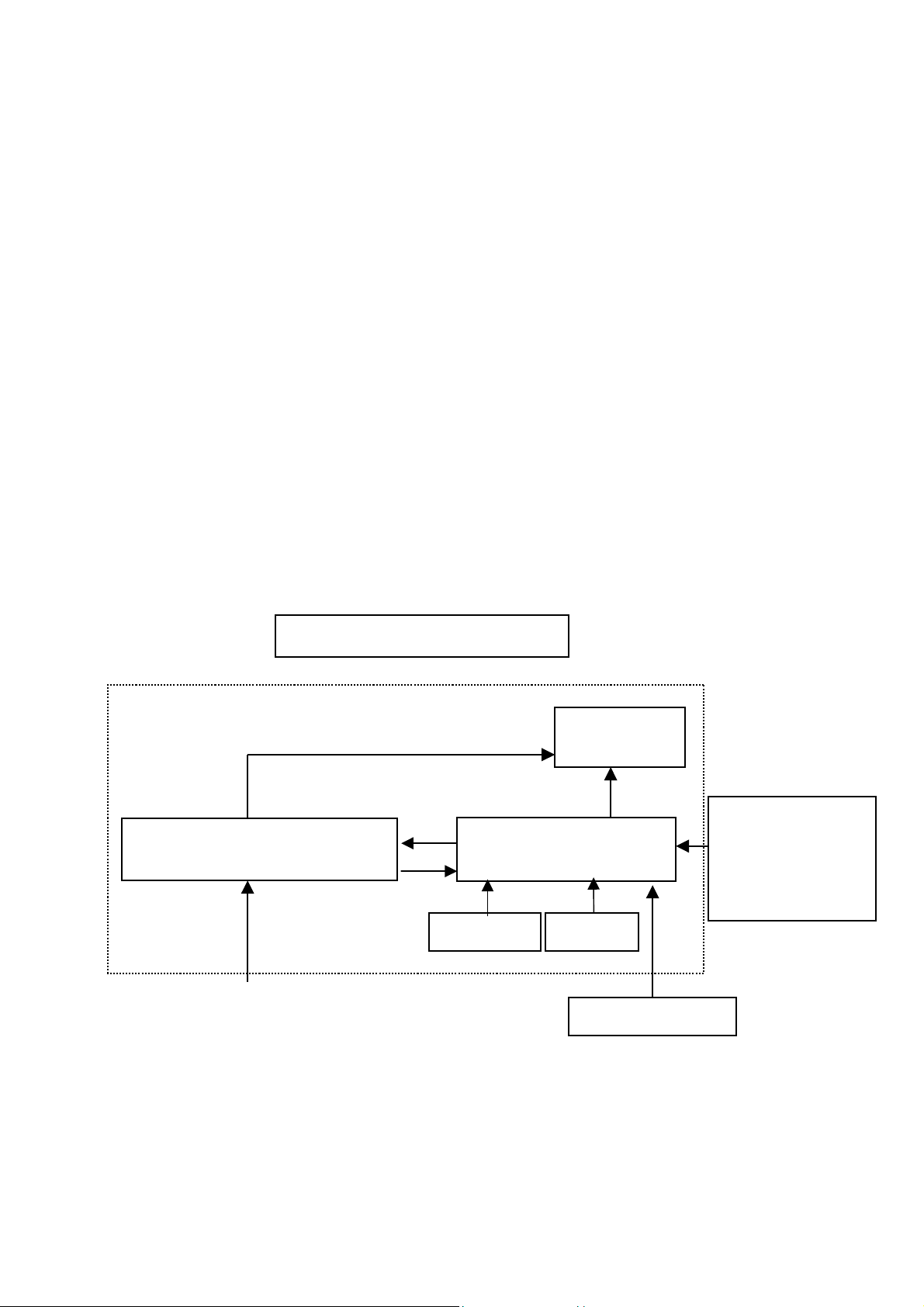
2. LCD MONITOR DESCRIPTION
The LCD MONITOR will contain a main board, a power board, a ke ypad boa rd and an audio b oard which house the flat
panel control logic, brightness control logic and DDC.
The power board will provide AC to DC Inverter voltage to drive the backlight of panel and the main board chip s each
voltage.
Include Adapter and Inverter
PWPC Board
Monitor Block Diagram
CCFT Drive.
Audio board
Flat Panel and
Main Board
Keyboard
CCFL
RS232 Connector
For white balance
adjustment in factory
mode
AC-IN
HOST Computer
100V-240V
4
Video signal, DDC
Page 5
LM-522 Service Manual
3. OPERATING INSTRUCTIONS
3.1 GENERAL INSTRUCTIONS
Press the power button to turn the monitor on or off. The other cont rol button s are located in the front of the monitor. By
changing these settings, the picture can be adjusted to your personal preferences.
• The power cord should be connected.
• Connect the video cable from the monitor to the video card.
• Press the power button to turn on the monitor position. The power indicator will light up.
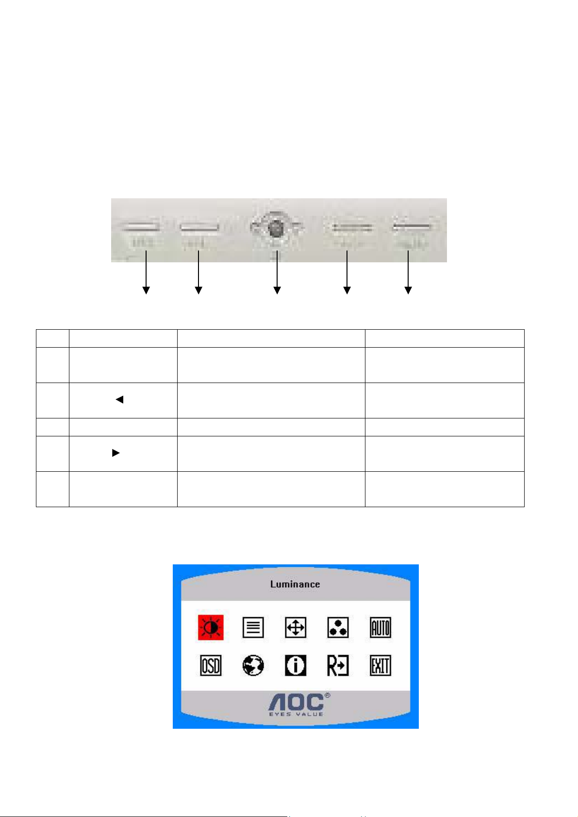
3.2 CONTROL BUTTONS
AUTO VOL- POWER VOL+ MENU
NO. Name Within OSD Without OSD
1 Auto
1. Exit Sub menu
2. Exit the menu item
1.Move the cursor to down
2 VOL - /
2.Adjust down when menu item selected
3 Power Turn on/off Turn on/off
1.Move the cursor to up
4 VOL + /
2.Adjust up when menu item selected
1.Enter the OSD sub menu
5 MENU
2.Select the OSD menu
Run the Auto Adjust when this
button keep to push for 2 second
Open the Brightness menu
Open the contrast menu
Open OSD menu
3.3 ADJUSTING THE PICTURE
5
Page 6
The descriptions for function control LEDS
LM-522 Service Manual
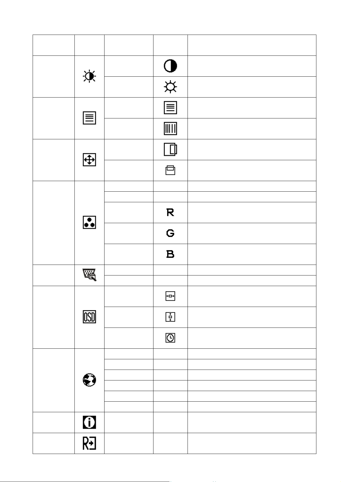
Main Menu
Item
Luminance
Image Setup
Image Position
Main
Menu Icon
Sub Menu Item
Description
Icon
Sub Menu
Contrast
Contrast from Digital-register
Brightness
Backlight Adjustment
Adjust Picture Phase to reduce Horizontal-Line
Focus
noise
Clock
Adjust picture Clock to reduce Vertical-Line noise.
H. Position
Adjust the horizontal position of the picture.
V. Position
Adjust the vertical position of the picture.
Warm N/A Recall Warm Color Temperature from EEPROM.
Cool N/A Recall Cool Color Temperature from EEPROM.
Color Temp.
OSD Setup
Language
OSD Timeout
User / Red
User / Green
User / Blue
Red Gain from Digital-register.
Green Gain Digital-register.
Blue Gain from Digital-register.
Analog N/A Select input signal from analog source (D-Sub) Input Select
Digital N/A Select input signal from digital source (DVI)
H. Position
V. Position
Adjust the horizontal position of the OSD.
Adjust the vertical position of the OSD.
Adjust the OSD timeout.
English N/A Set OSD display language to English.
Deutsch N/A Set OSD display language to German.
Français N/A Set OSD display language to French.
Español N/A Set OSD display language to Spain.
Information
Reset
Italiano N/A Set OSD display language to Italian.
Simplified Chinese N/A Set OSD display language to Simplified Chinese.
Show the resolution, H/V frequency and input port
Information N/A
of current input timing.
Clear each old status of Auto-configuration and set
Yes N/A
the color temperature to Cool.
6
Page 7
LM-522 Service Manual
No N/A Do not execute reset, return to main menu.
Exit
N/A N/A Exit OSD
4. Input/ Output Specification
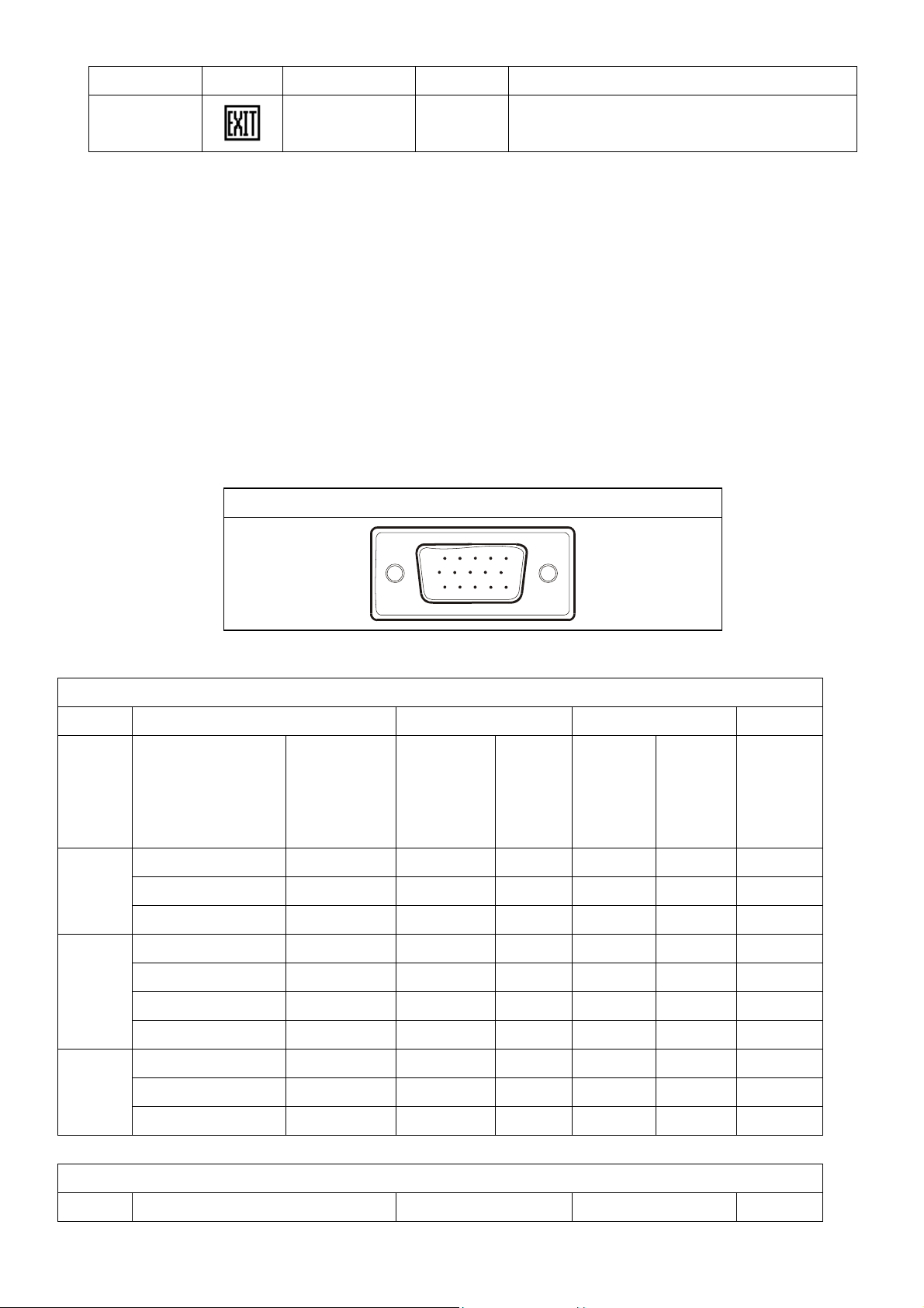
4.1 Input Signal Connector
1 Red Video 9 +5 v
2 Green Video 10 Logic Ground
3 Blue Video 11 RS-232 RX
4 RS-232 TX 12 DDC-Serial Data
5 DDC-Return 13 H-Sync.
6 Red Ground 14 V-Sync.
7 Green Ground 15 DDC-Serial Clock
8 Blue Ground
CONNECTOR PIN ASSIGNMENT
15
6
11 15
10
4.2 Factory Preset Display Modes
VESA MODES
Horizontal Vertical
Mode Resolution Total
640x480@60Hz 800 x 525 31.469 N 59.940 N 25.175
VGA
640x480@72Hz 832 x 520 37.861 N 72.809 N 31.500
640x480@75Hz 840 x 500 37.500 N 75.00 N 31.500
800x600@56Hz 1024 x 625 35.156 N/P 56.250 N/P 36.000
800x600@60Hz 1056 x 628 37.879 P 60.317 P 40.000
SVGA
800x600@72Hz 1040 x 666 48.077 P 72.188 P 50.000
800x600@75Hz 1056x625 46.875 P 75.000 P 49.500
1024x768@60Hz 1344x806 48.363 N 60.004 N 65.000
Nominal
Frequency
+/- 0.5kHz
Sync
Polarity
Nominal
Freq.
+/- 1 Hz
Sync
Polarity
Nominal
Pixel
Clock
(MHz)
XGA
1024x768@70Hz 1328x806 56.476 N 70.069 N 75.000
1024x768@75Hz 1312x800 60.023 P 75.029 P 78.750
IBM MODES
Horizontal Vertical
7
Page 8
LM-522 Service Manual
Nominal
Mode Resolution Total
DOS 720x400@70Hz 900 x 449 31.469 N 70.087 P 28.322
DOS 640x350@70Hz 800 x 449 31.469 P 70.087 N 25.175
XGA 1024x768@72Hz 1304x798 57.515 P 72.100 P 75.000
MAC MODES
VGA
640x480@67Hz 864x525 35.000 N 66.667 N 30.240
SVGA
832x624@75Hz 1152x667 49.725 N 74.551 N 57.2832
XGA 1024x768@75Hz 1328x804 60.241 N 74.927 N 80.000
Frequency
+/- 0.5kHz
Sync
Polarity
Nominal
Sync
Freq.
Polarity
+/- 1 Hz
Nominal
Pixel
Clock
(MHz)
4.3 Power Supply Requirements
A/C Line voltage range : 100 V ~ 240 V
A/C Line frequency range
Current : 0.6A max. at 100V , 0.35A max. at 240 V <0.3A
Peak surge current : < 55A peak at 240 VAC and cold starting
Leakage current : < 3.5mA
Power line surge : No advance effects (no loss of information or defect)
Voltage : 12VDC ± 5 %
Current : 3.5max
4.4 PANEL SPECIFICATION
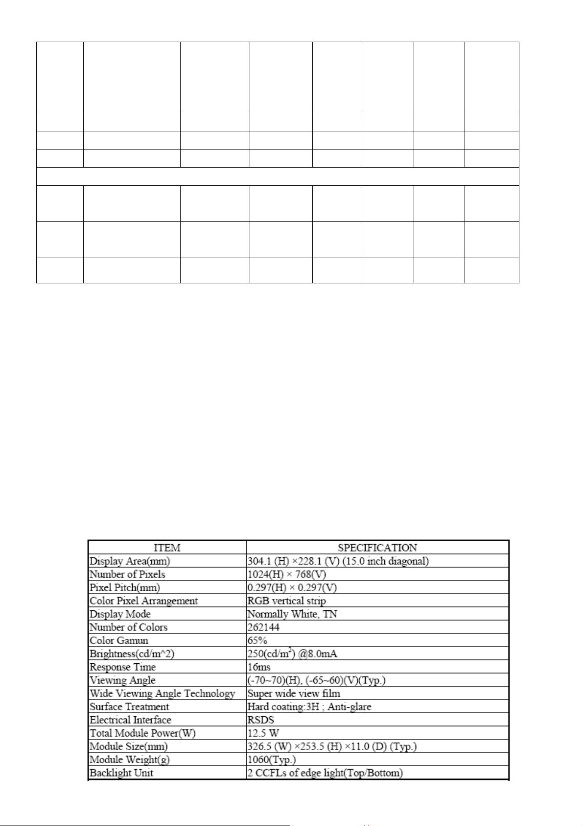
4.4.1 Panel Feature
: 50 ± 3Hz, 60 ± 3Hz
with a maximum of 1 half-wave missing per second
8
Page 9
4.4.2 Display Characteristics
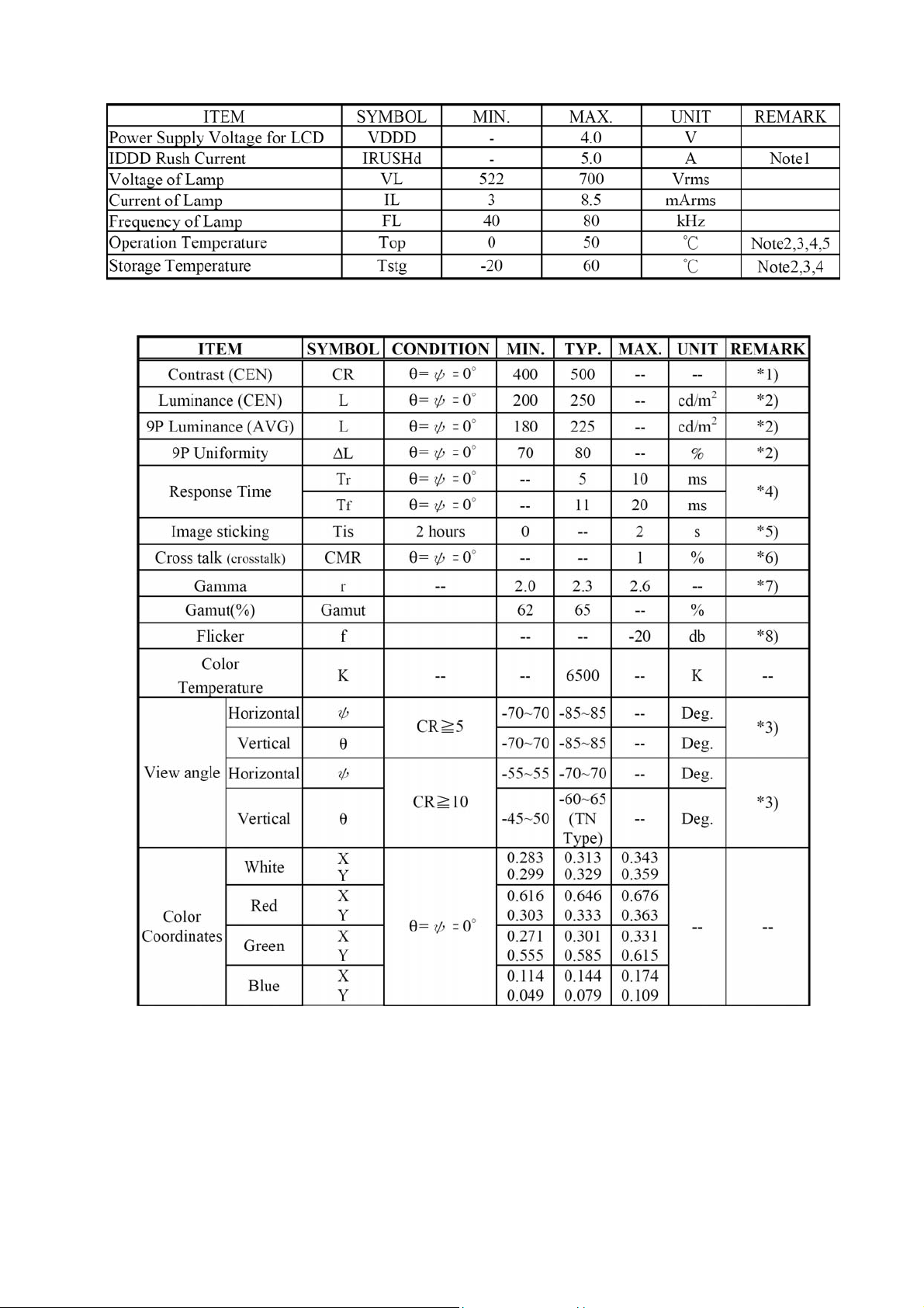
4.4.3 Optical Characteristics
LM-522 Service Manual
9
Page 10
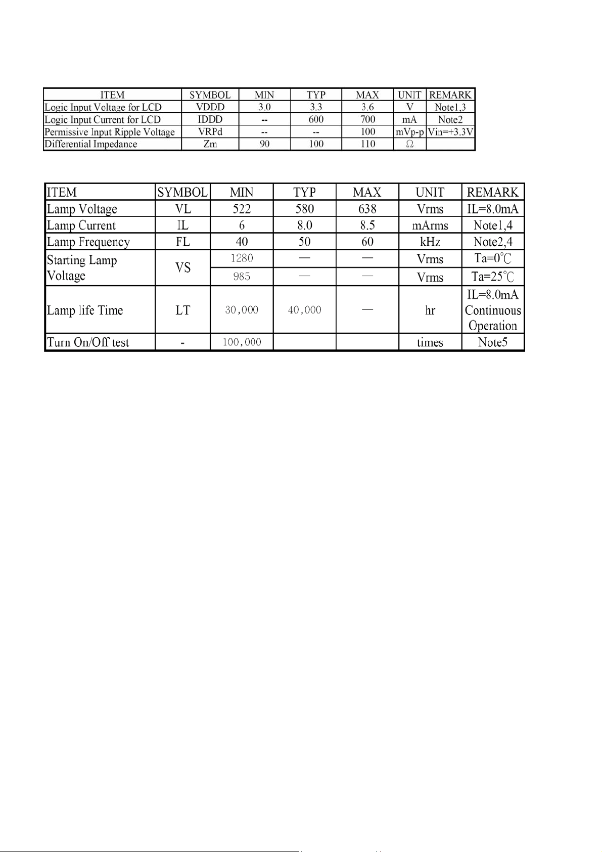
4.4.4 Parameter guideline for CCFL Inverter
4.4.5 Back-light Unite
LM-522 Service Manual
10
Page 11
5. Block Diagram
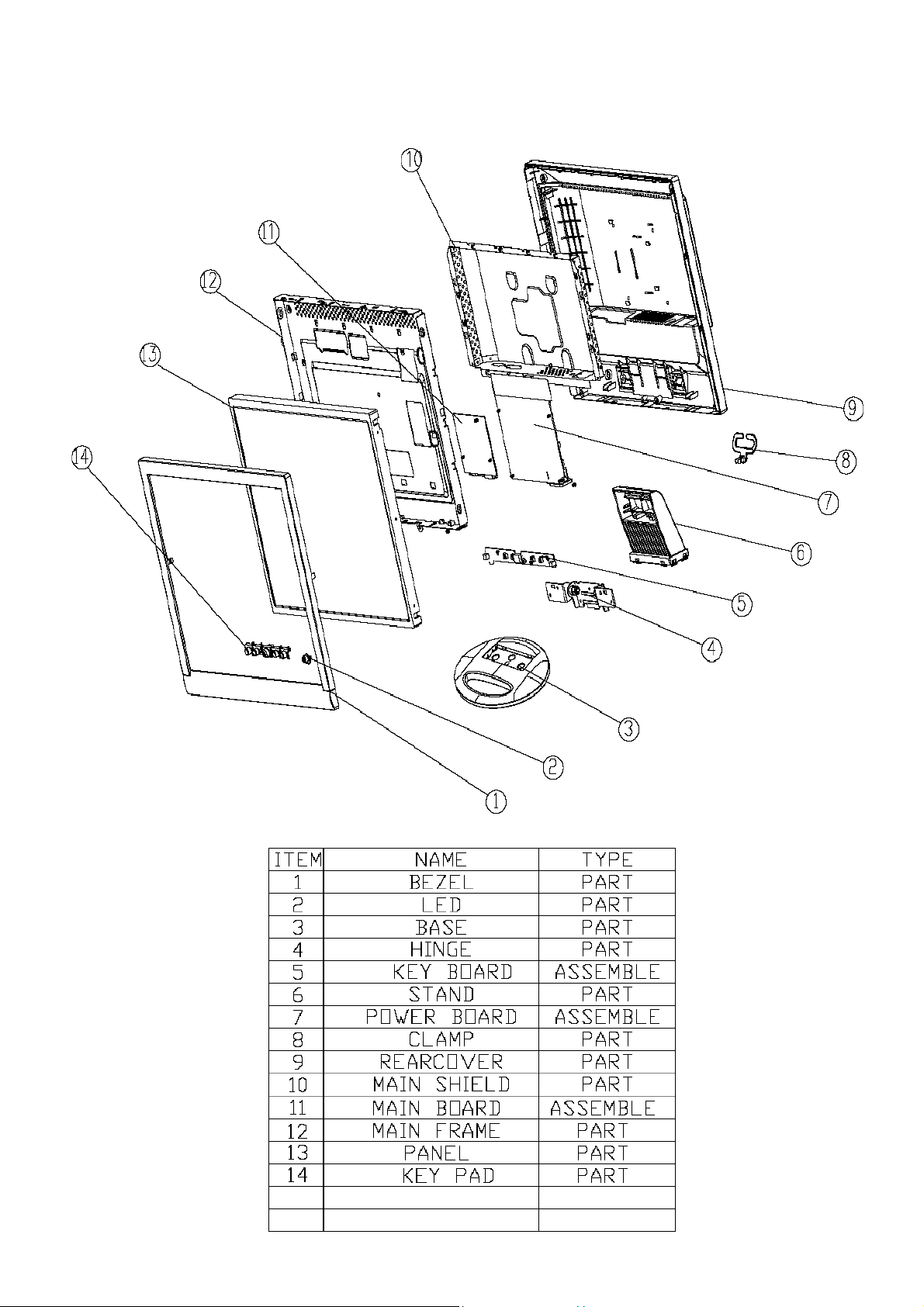
5.1 Monitor Exploded View
LM-522 Service Manual
11
Page 12
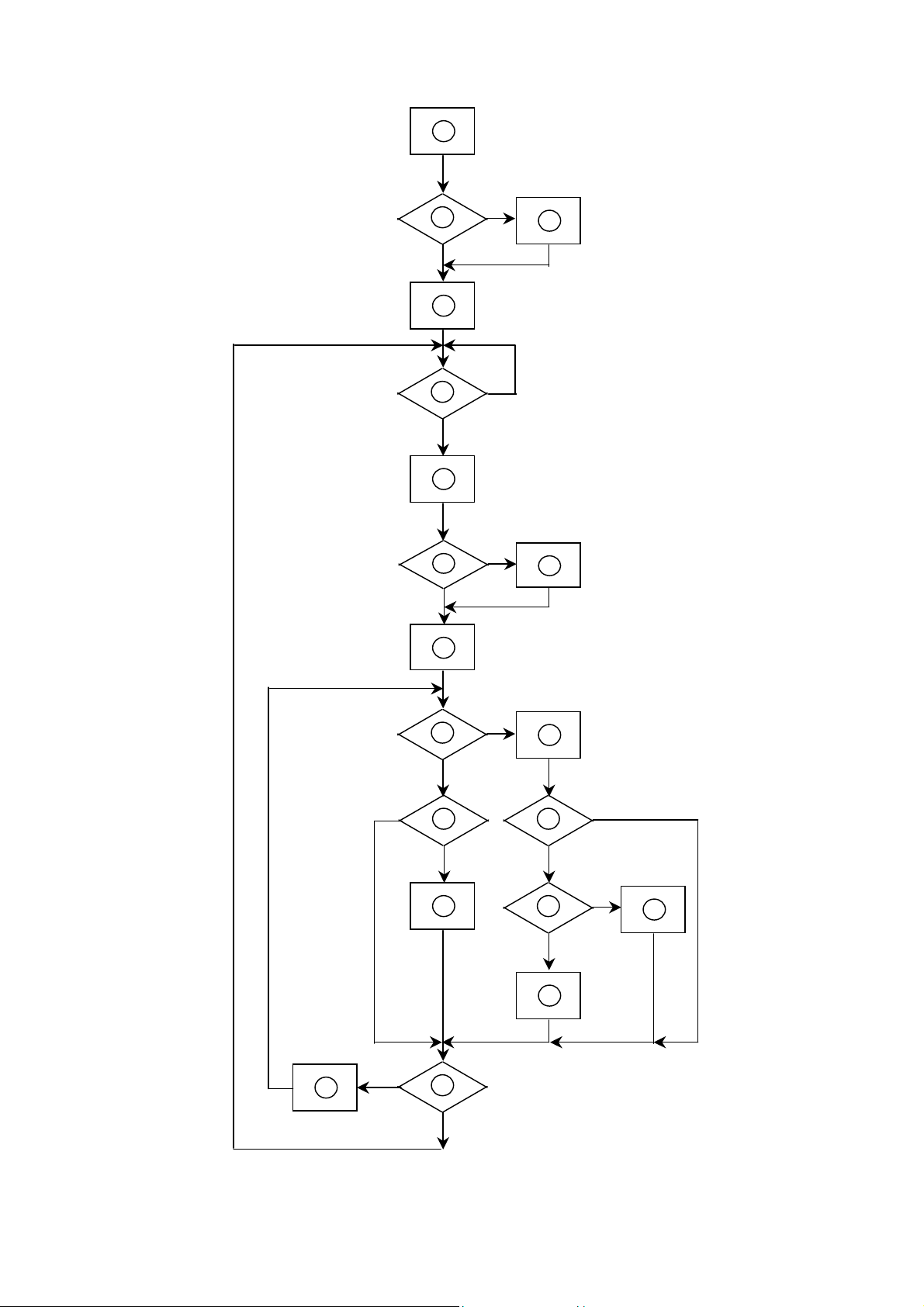
5.2 Software Flowing Chart
LM-522 Service Manual
1
2
4
Y
N
3
5
6
9
10
N
12
N
Y
N
7
Y
N
Y
11
13
8
N
18
Y
14
N
19
Y
12
15
17
Y
N
Y
16
Page 13

1) MCU initialize
2) Is the EPROM blank?
3) Program the EPROM by default values.
4) Get the PWM value of brightness from EPROM.
5) Is the power key pressed?
6) Clear all global flags.
7) Are the AUTO and SELECT keys pressed?
8) Enter factory mode.
9) Save the power key status into EPROM. Turn on the LED and set it to green color.
Scaler initialize.
10) In standby mode?
11) Update the lifetime of back light.
12) Check the analog port, are there any signals coming?
13) Does the scalar send out an interrupt request?
14) Wake up the scalar.
15) Are there any signals coming from analog port?
LM-522 Service Manual
16) Display "No connection Check Signal Cable" message. And go into standby mode after the message
disappears.
17) Program the scalar to be able to show the coming mode.
18) Process the OSD display.
19) Read the keyboard. Is the power key pressed?
13
Page 14

5.3 Electrical Block Diagram
5.3.1 Main Board
LM-522 Service Manual
5.3.2 Inverter/Power Board
Vin
Vin
Inverter Block Diagram
Buck Connector
Driver
Circuit
P arallet-reso na nt
inverter
Dim m ing control
(PW M )
(· §² ¤ ¹ Ï )
Pa rallet-reso nan t
inv e rter
CCFL
Driver
Circuit
Dim m ing control
PW M
14
Page 15

Power Block Diagram
LM-522 Service Manual
15
Page 16

6. Schematic
6.1 Main Board
LM-522 Service Manual
16
Page 17

LM-522 Service Manual
17
Page 18

LM-522 Service Manual
18
Page 19

LM-522 Service Manual
19
Page 20

LM-522 Service Manual
20
Page 21

6.2 Power board
LM-522 Service Manual
21
Page 22

LM-522 Service Manual
22
Page 23

7. PCB Layout
7.1 Main Board
LM-522 Service Manual
23
Page 24

7.2Power board
LM-522 Service Manual
24
Page 25

7.3 Keypad Board
7.4 Audio Board
LM-522 Service Manual
25
Page 26

8. Maintainability
8.1 Requirements and Tools Requirement
1. Voltmeter.
2. Oscilloscope.
3. Pattern Generator.
4. DDC Tool with an IBM Compatible Computer.
5. Alignment Tool.
6. LCD Color Analyzer.
7. Service Manual.
8. User Manual.
LM-522 Service Manual
26
Page 27

8.2 Trouble Shooting
8.2.1 Main Board
1. NO SCREEN APPEAR
2.
Measured CN105 pin5/pin6 =12 V?
Measured CN105 pin9/pin10 =5V?
Measured U501 pin 2= 3.3V?
Measured U502 pin2=2.5V?
Yes, all DC level exist
Disconnected the Signal cable (Loose the
Signal cable), Is the screen show “Cable Not
Connected”?
Yes, there is OSD show
LM-522 Service Manual
Check Correspondent component.
Is there any shortage or cold solder?
Connected the Signal cable again,
Check LED status.
Led Green
No, nothing is show
Connected the Signal cable
again
Led Green
Check the Wire-Harness from CN109
Check Panel-Power Circuit Block
OK, Wire tight enough
Check U102 Data-output Block
OK, Panel Power OK
Led Orange
OK
Check Power switch is in Power-on
status, and check whether Power
switch had been stuck?
OK, Keyboard no stuck
Measured RGB (R166, R169, R173)
H, V Input at 102 pin119,126,was
there signal?
Measured Crystal X101 (12MHz)
Replace U101
Led orange
Check Correspondent
component short/open
(Protection Diode)
NG
OK, input Normal
OK, clock normal
Replace Power board and Check
Inverter control relative circuit
Replace U102 (NT68521A-XFG)
Re-do White balance adjust
OK
Note:1. If replace “MAIN-BOARD”, Please re-do “DDC-content” programmed & “WHITE-Balance”.
2. If replace “Power Board” only, Please re-do “ WHITE-Balance”
27
Page 28

2. PANEL POWER CIRCUIT
LM-522 Service Manual
NG
Check R162 should have response from 0V to 5V
When we switch the power switch from off to on
OK
Check Q102, Q101 is broken or CN109 solder abnormal?
OK
NG
Replace Q102, Q101 or re-solder CN109
Replace Panel
3. INVERTER CONTROL RELATIVE CIRCUIT
Measured the inverter connector
CN102
Pin1 on/off control=5V (on)
Pin2 PWM signal control dim 0V-5V
OK
Replace Power board
& Re-do white balance
NG
NG
Measured X101 waveform is normal?
NG
OK
Replace U101
Check the Bklt-On relative circuit, R201, Q201,
In normal operation, when LED =green,
Base of Q201 should =0 V,
In saving mode, when LED=orange,
Base of Q201 should =5V,
Replace U101
Replace X101
OK
28
Page 29

4. U4-DATA OUTPUT
Check NT68521A-XFG (U102)
Signal output (PIN64-69,
PIN50-55,PIN 41-46)
Is the waveform ok?
LM-522 Service Manual
NG
Measured X101 waveform is
normal?
NG
Replace X101
OK
OK
Replace U101
8.2.2 Key Pad Board
OK
OSD is unstable or not working
Is Key Pad Board connecting normally?
Check HS/VS input signal are
normal?
Check relative component
Y
NG
N
Connect Key Pad Board
Is Button Switch normally?
Y
Is Key Pad Board Normally?
Y
Check Main Board
29
N
Replace Button Switch
N
Replace Key Pad Board
Page 30

LM-522 Service Manual
9. White-Balance, Luminance adjustment
Approximately 30 minutes should be allowed for warm up before proceeding white balance adjustment.
Before started adjust white balance ,please setting the Chroma-7120 MEM. channel 1 to 6500 color, MEM. channel 2
to 7800 color ( our 6500 parameter is x = 313 ±10, y = 329 ±10, Y = 200 ±10 cd/m
311 ±10, Y = 200 ±10 cd/m
2
)
How to setting MEM.channel you can reference to chroma 7120 use r guide or simple u se “ SC” key and “ NEXT” key to
modify xyY value and use “ID” key to modify the TEXT description
Following is the procedure to do white-balance adjust
Press MENU button during 2 seconds along with press Power button will activate the factory mode, then MCU will do
AUTO LEVEL automatically. Meanwhile press MENU the OSD screen will located at left top of panel.
2 ,
7200 parameter is x = 296 ±10, y =
Bias adjustment :
set the contrast
adjust the Bri ghtness
Gain adjustment :
to 70.
to 90.
Move cursor to “-Factory-” and press MENU key
adjust 6500 color-temperature
Switch the chroma-7120 to RGB-mode (with press “MODE” button )
switch the MEM.channel to Channel 01 ( with up or down arrow on chroma 7120 )
The lcd-indicator on chroma 7120 will show x = 313 ±10, y = 329 ±10, Y = 200 ±5 cd/m
2
Adjust the RED on OSD window until chroma 7120 indicator reach ed the value R=100
adjust the GREEN on OSD, until chroma 7120 indicator reached G=100
adjust the BLUE on OSD, until chroma 7120 indicator reached B=100
repeat above procedure ( item 5,6,7) until chroma 7120 RGB value meet the tolence =100±2
Press Exit on OSD window to save the adjustment result
adjust 7800 color-temperature
Switch the chroma-7120 to RGB-mode (with press “MODE” button )
switch the MEM.channel to Channel 02 ( with up or down arrow on chroma 7120 )
The lcd-indicator on chroma 7120 will show x = 296 ±10, y = 311 ±10, Y = 200 ±5 cd/m
2
Adjust the RED on OSD window until chroma 7120 indicator reach ed the value R=100
adjust the GREEN on OSD, until chroma 7120 indicator reached G=100
adjust the BLUE on OSD, until chroma 7120 indicator reached B=100
repeat above procedure ( item 5,6,7) until chroma 7120 RGB value meet the tolence =100±2
Press Exit on OSD window to save the adjustment result
Turn the POWER-button off to on to quit from factory mode.
30
Page 31

LM-522 Service Manual
10. EDIT Content
00 01 02 03 04 05 06 07 08 09 10 11 12 13 14 15
00 00 FF FF FF FF FF FF 00 05 E3 22 A5 0B 95 0D 00
16: 0C 0F 01 03 68 1E 17 82 2A 8F 3D A4 58 4D 90 24
32: 15 4F 51 BF EE 00 01 01 01 01 01 01 01 01 01 01
48: 01 01 01 01 01 01 64 19 00 40 41 00 26 30 18 88
64: 36 00 30 E4 10 00 00 18 00 00 00 FF 00 31 32 33
80: 34 35 36 37 38 39 30 31 32 33 00 00 00 FD 00 37
96: 4B 1E 3F 08 00 0A 20 20 20 20 20 20 00 00 00 FC
112 00 4C 4D 35 32 32 0A 20 20 20 20 20 20 20 00 39
31
Page 32

LM-522 Service Manual
11.BOM LIST
T560KCNHKAACA
M1L 330 4128 SCREW M3X4 P 4 PCS
AUPC560KB9 AUDIO BOARD M 1 PCS
CBPC560KCNAA CONVERSION BOARD M 1 PCS
KEPC560KDB KEY BOARD M 1 PCS
PWPC5215A1E20C POWER BOARD M 1 PCS
15G5791 1 VESA BKT P 1 PCS
15G5908 2 BRACKET P 1 PCS
15G5935 24 MAIN FRAME P 1 PCS
33G4693 AI T L703A-C1-KEY(NMV) P 1 PCS
33G4694 1 C POWER LENS P 1 PCS
34L1274 IW T BASE P 1 PCS
34L1295AGN 1T FRONT PANEL P 1 PCS
34L1298 IW 2T REAR COVER P 1 PCS
40G 150615 1 ID LABEL P 1 PCS
40G 58162435A LABEL P 1 PCS
44L3231 15 EVA WASHER P 1 PCS
44L3525624 1A CARTON P 1 PCS
44L3553 1 EPS(L) P 1 PCS
44L3553 2 EPS(R) P 1 PCS
45L 88607DE2 PE PAG P 1 PCS
45L 88609 EPE COVER P 1 PCS
52L 1211 A ALUMINIUM TAPE P 1 PCS
52L6025 11702 INSULATE SHEET P 1 PCS
78L 314 2 4028 SPEAKER 8OHM 1W P 2 PCS
85L 654 3 SHIELD P 1 PCS
89G176J 50509 FPC P 1 PCS
89L 173 56509 AUDIO HARNESS P 1 PCS
89L1738LAA D1 D-SUB SIGNAL CABLE P 1 PCS
89L401A18NHRA POWER CORD P 1 PCS
95G8014 14625 WIRE HARNESS P 1 PCS
95G8014 16584 WIRE HARNESS P 1 PCS
M1L 330 4128 SCREW M3X4 P 1 PCS
M1L 330 6 47 SCREW 3X6mm P 4 PCS
M1L1140 5128 SCREW 4X5 P 1 PCS
M1L1730 6128 SCREW M3x6 P 10 PCS
Q1L 330 6120 SCREW M3X6mm P 4 PCS
Q1L 330 10 47 SCREW (T3X10) P 1 PCS
32
Page 33

750LLC50P02 CPT 15" XP02 PANEL P 1 PCS
AM1L1740 10 47 SCREW P 4 PCS
AUPC560KB9
AUPC560KB4SMT AUDIO BOARD FOR T560K* M 1 PCS
CN202 33L801714A PIN HEADER 2*7P 2.0mm P 1 PCS
CN204 95G8014 3503 WIRE HARNESS P 1 PCS
U201 56L 616 1 TDA7496L BY ST P 1 PCS
AUPC560KB4AI AUDIO BOARD FOR T560K* M 1 PCS
C203 65L0805104 32 CHIP 0.1UF 50V X7R P 1 PCS
C204 65L0805474 22 CHIP 0.47UF 25V X7R 080 P 1 PCS
C206 65L0805474 22 CHIP 0.47UF 25V X7R 080 P 1 PCS
C211 65L0805101 31 CHIP 100PF 50V NPD 0805 P 1 PCS
C212 65L0805101 31 CHIP 100PF 50V NPD 0805 P 1 PCS
C213 65L0805104 32 CHIP 0.1UF 50V X7R P 1 PCS
R201 61L0603183 CHIP 18K O HM 1/10 W P 1 PCS
LM-522 Service Manual
R203 61L0603183 CHIP 18K O HM 1/10 W P 1 PCS
R207 61L0603102 CHIPR 1K OHM +-5% 1/10W P 1 PCS
R208 61L0603102 CHIPR 1K OHM +-5% 1/10W P 1 PCS
R210 61L0603203 CHIPR 20K OHM+-5% 1/10W P 1 PCS
R211 61L0603203 CHIPR 20K OHM+-5% 1/10W P 1 PCS
715L1144 1 IO AUDIO BOARD P 1 PCS
C201 67L 3054713XT 470 uf 16v P 1 PCS
C202 67L 3054713XT 470 uf 16v P 1 PCS
C205 67L 3054713XT 470 uf 16v P 1 PCS
C207 67L 3054713XT 470 uf 16v P 1 PCS
C208 67L 3054713XT 470 uf 16v P 1 PCS
C209 67L 3091097XT 1.0uF +-20% 50V P 1 PCS
C210 67L 3091097XT 1.0uF +-20% 50V P 1 PCS
R212 61L 6022015 2T CFR 200 OHM +-5% 1/6W P 1 PCS
CBPC560KCNAA
AIC560KCNAA MAIN BOARD M 1 PCS
40G 45762412B CBPC LABEL P 1 PCS
C102 67L309V470 3 47UF 16V 85C P 1 PCS
C106 67L309V470 3 47UF 16V 85C P 1 PCS
C120 67L309V470 3 47UF 16V 85C P 1 PCS
C125 67L309V470 3 47UF 16V 85C P 1 PCS
C127 67L305V471 3K 470UF 16V P 1 PCS
C136 67L309V470 3 47UF 16V 85C P 1 PCS
C155 67L305V101 7K 100UF 50V P 1 PCS
33
Page 34

LM-522 Service Manual
C159 67L305M101 3K 100UF 16V 105C +-20% P 1 PCS
C160 67L305M101 3K 100UF 16V 105C +-20% P 1 PCS
C167 67L305V101 7K 100UF 50V P 1 PCS
C178 67L305V101 3 1000UF +-2 16V P 1 PCS
C179 67L305V101 3 1000UF +-2 16V P 1 PCS
CN102 33L8027 16 WAFER 16PIN 2.0mm DIP P 1 PCS
CN105 33L8027 12 WAFER 2*6P 2.0MM R/A P 1 PCS
CN106 33L8027 14 WAFER 14P 2.0MM DIP DUA P 1 PCS
CN107 88L 35315F HS D-SUB 15PIN FEMALE P 1 PCS
MTG U10 90L6077 1 HEAT SZIVK P 1 PCS
X101 93G 22 51 CRYSTAL 12MHz HC-49US A P 1 PCS
40G 457624 1B CPU LABEL P 1 PCS
715L1365 2 PCB P 1 PCS
C101 65L0603105 17 1UF 16V Y5V P 1 PCS
C103 65L0603104 32 CHIP 0.1UF 50V X7R P 1 PCS
C104 65L0603220 31 CHIP 22PF 50V NPO P 1 PCS
C105 65L0603220 31 CHIP 22PF 50V NPO P 1 PCS
C109 65L0603104 32 CHIP 0.1UF 50V X7R P 1 PCS
C110 65L0603101 31 CHIP 100PF 50V NPO P 1 PCS
C111 65L0603105 17 1UF 16V Y5V P 1 PCS
C112 65L0603224 17 CAP:CER 0.22UF-20%-80% P 1 PCS
C113 65L0603221 31 CAP:CER 220PF 5% 50V SM P 1 PCS
C114 65L0603221 31 CAP:CER 220PF 5% 50V SM P 1 PCS
C115 65L0603221 31 CAP:CER 220PF 5% 50V SM P 1 PCS
C116 65L0603221 31 CAP:CER 220PF 5% 50V SM P 1 PCS
C117 65L0603221 31 CAP:CER 220PF 5% 50V SM P 1 PCS
C118 65L0603221 31 CAP:CER 220PF 5% 50V SM P 1 PCS
C119 65L0603221 31 CAP:CER 220PF 5% 50V SM P 1 PCS
C121 65L0603104 32 CHIP 0.1UF 50V X7R P 1 PCS
C122 65L0603104 32 CHIP 0.1UF 50V X7R P 1 PCS
C123 65L0603104 32 CHIP 0.1UF 50V X7R P 1 PCS
C124 65L0603104 32 CHIP 0.1UF 50V X7R P 1 PCS
C126 65L0603104 32 CHIP 0.1UF 50V X7R P 1 PCS
C128 65L0603104 32 CHIP 0.1UF 50V X7R P 1 PCS
C129 65L0603104 32 CHIP 0.1UF 50V X7R P 1 PCS
C130 65L0603104 32 CHIP 0.1UF 50V X7R P 1 PCS
C131 65L0603104 32 CHIP 0.1UF 50V X7R P 1 PCS
C132 65L0603104 32 CHIP 0.1UF 50V X7R P 1 PCS
C133 65L0603104 32 CHIP 0.1UF 50V X7R P 1 PCS
34
Page 35

C134 65L0603104 32 CHIP 0.1UF 50V X7R P 1 PCS
C135 65L0603104 32 CHIP 0.1UF 50V X7R P 1 PCS
C137 65L0603104 32 CHIP 0.1UF 50V X7R P 1 PCS
C138 65L0603103 32 0.01UF+-10% 50V X7R P 1 PCS
C139 65L0603103 32 0.01UF+-10% 50V X7R P 1 PCS
C140 65L0603103 32 0.01UF+-10% 50V X7R P 1 PCS
C141 65L0603103 32 0.01UF+-10% 50V X7R P 1 PCS
C142 65L0603103 32 0.01UF+-10% 50V X7R P 1 PCS
C143 65L0603103 32 0.01UF+-10% 50V X7R P 1 PCS
C144 65L0603103 32 0.01UF+-10% 50V X7R P 1 PCS
C149 65L0603104 32 CHIP 0.1UF 50V X7R P 1 PCS
C151 65L0603104 32 CHIP 0.1UF 50V X7R P 1 PCS
C152 65L0603104 32 CHIP 0.1UF 50V X7R P 1 PCS
C153 65L0603104 32 CHIP 0.1UF 50V X7R P 1 PCS
C154 65L0603104 32 CHIP 0.1UF 50V X7R P 1 PCS
LM-522 Service Manual
C156 65L0603104 32 CHIP 0.1UF 50V X7R P 1 PCS
C157 65L0603221 31 CAP:CER 220PF 5% 50V SM P 1 PCS
C158 65L0603221 31 CAP:CER 220PF 5% 50V SM P 1 PCS
C161 65L0603104 32 CHIP 0.1UF 50V X7R P 1 PCS
C162 65L0603104 32 CHIP 0.1UF 50V X7R P 1 PCS
C164 65L0603221 31 CAP:CER 220PF 5% 50V SM P 1 PCS
C165 65L0603221 31 CAP:CER 220PF 5% 50V SM P 1 PCS
C166 65L0603221 31 CAP:CER 220PF 5% 50V SM P 1 PCS
C168 65L0603104 32 CHIP 0.1UF 50V X7R P 1 PCS
C169 65L0603104 32 CHIP 0.1UF 50V X7R P 1 PCS
C171 65L0603102 32 1000PF +-10% 50V X7R P 1 PCS
C172 65L0603102 32 1000PF +-10% 50V X7R P 1 PCS
C173 65L0603220 31 CHIP 22PF 50V NPO P 1 PCS
C174 65L0603220 31 CHIP 22PF 50V NPO P 1 PCS
C175 65L0603104 32 CHIP 0.1UF 50V X7R P 1 PCS
C177 65L0603101 31 CHIP 100PF 50V NPO P 1 PCS
C180 65L0603101 31 CHIP 100PF 50V NPO P 1 PCS
C181 65L0603101 31 CHIP 100PF 50V NPO P 1 PCS
C182 65L0603680 31 CHIP 68PF 50V NPO P 1 PCS
C183 65L0603680 31 CHIP 68PF 50V NPO P 1 PCS
C184 65L0603680 31 CHIP 68PF 50V NPO P 1 PCS
C185 65L0603105 17 1UF 16V Y5V P 1 PCS
C186 65L0603105 17 1UF 16V Y5V P 1 PCS
CN109 33L8019 50 CONNECTOR 50P P 1 PCS
35
Page 36

LM-522 Service Manual
D101 93L 60230 BAT54C(L43) P 1 PCS
D104 56L 158501 AZ431AN-A SOT23-3 P 1 PCS
D105 93G 6433P BAV99 P 1 PCS
D106 93G 6433P BAV99 P 1 PCS
D107 93G 6433P BAV99 P 1 PCS
D108 93G 6432V LL4148-GS08 P 1 PCS
D109 93G 6432V LL4148-GS08 P 1 PCS
D110 93G 6432V LL4148-GS08 P 1 PCS
D111 93G 6432V LL4148-GS08 P 1 PCS
D112 93G 39147 TZMC5V6 P 1 PCS
D113 93G 39147 TZMC5V6 P 1 PCS
D114 93G 39147 TZMC5V6 P 1 PCS
L100 61L0805000 CHIP O OHM 1/8W P 1 PCS
L101 71L 56Z601 CHIP BEAD 600 OHM 0805 P 1 PCS
L102 71L 56Z601 CHIP BEAD 600 OHM 0805 P 1 PCS
L103 71L 56Z601 CHIP BEAD 600 OHM 0805 P 1 PCS
L108 61L0805000 CHIP O OHM 1/8W P 1 PCS
L109 61L0805000 CHIP O OHM 1/8W P 1 PCS
L115 61L1206000 4 0 OHM 4A 1/4W P 1 PCS
Q102 57G 417 4 PMBS3904/PHILIPS-SMT(04 P 1 PCS
R101 61L0603472 CHIPR 4.7K OHM +-5% 1/1 P 1 PCS
R103 61L0603102 CHIPR 1K OHM +-5% 1/10W P 1 PCS
R104 61L0603102 CHIPR 1K OHM +-5% 1/10W P 1 PCS
R107 61L0603472 CHIPR 4.7K OHM +-5% 1/1 P 1 PCS
R11 1 61L0603105 CHIPR 1M OHM+-5% 1/10W P 1 PCS
R114 61L0603101 CHIPR 100 OHM +-5% 1/10 P 1 PCS
R115 61L0603101 CHIPR 100 OHM +-5% 1/10 P 1 PCS
R116 61L0603472 CHIPR 4.7K OHM +-5% 1/1 P 1 PCS
R117 61L0603472 CHIPR 4.7K OHM +-5% 1/1 P 1 PCS
R118 61L0603472 CHIPR 4.7K OHM +-5% 1/1 P 1 PCS
R119 61L0603472 CHIPR 4.7K OHM +-5% 1/1 P 1 PCS
R120 61L0603472 CHIPR 4.7K OHM +-5% 1/1 P 1 PCS
R121 61L0603682 CHIP 6.8K OHM 1/10W P 1 PCS
R125 61L0603153 CHIPR 15KOHM+-5% 1/10W P 1 PCS
R129 61L0603102 CHIPR 1K OHM +-5% 1/10W P 1 PCS
R130 61L0603102 CHIPR 1K OHM +-5% 1/10W P 1 PCS
R131 61L0603102 CHIPR 1K OHM +-5% 1/10W P 1 PCS
R132 61L0603101 CHIPR 100 OHM +-5% 1/10 P 1 PCS
R133 61L0603101 CHIPR 100 OHM +-5% 1/10 P 1 PCS
36
Page 37

R134 61L0603102 CHIPR 1K OHM +-5% 1/10W P 1 PCS
R135 61L0603102 CHIPR 1K OHM +-5% 1/10W P 1 PCS
R136 61L0603101 CHIPR 100 OHM +-5% 1/10 P 1 PCS
R137 61L0603101 CHIPR 100 OHM +-5% 1/10 P 1 PCS
R140 61L0603220 CHIPR 22 OHM+-5% 1/10W P 1 PCS
R141 61L0603220 CHIPR 22 OHM+-5% 1/10W P 1 PCS
R142 61L0603220 CHIPR 22 OHM+-5% 1/10W P 1 PCS
R143 61L0603220 CHIPR 22 OHM+-5% 1/10W P 1 PCS
R144 61L0603220 CHIPR 22 OHM+-5% 1/10W P 1 PCS
R145 61L0603220 CHIPR 22 OHM+-5% 1/10W P 1 PCS
R146 61L0603821 CHIP RES .0603/820/J 1/ P 1 PCS
R147 61L0603101 CHIPR 100 OHM +-5% 1/10 P 1 PCS
R148 61L0603101 CHIPR 100 OHM +-5% 1/10 P 1 PCS
R149 61L0603101 CHIPR 100 OHM +-5% 1/10 P 1 PCS
R154 61L0603101 CHIPR 100 OHM +-5% 1/10 P 1 PCS
LM-522 Service Manual
R155 61L0603101 CHIPR 100 OHM +-5% 1/10 P 1 PCS
R156 61L0603220 CHIPR 22 OHM+-5% 1/10W P 1 PCS
R157 61L0603220 CHIPR 22 OHM+-5% 1/10W P 1 PCS
R163 61L0603473 CHIP 47K O HM 1/10 W P 1 PCS
R165 61L0603104 CHIPR 100K OHM +-5% 1/1 P 1 PCS
R166 61L0603101 CHIPR 100 OHM +-5% 1/10 P 1 PCS
R167 61L0603750 9F 75OHM 1% 1/10W P 1 PCS
R168 61L0603101 CHIPR 100 OHM +-5% 1/10 P 1 PCS
R169 61L0603101 CHIPR 100 OHM +-5% 1/10 P 1 PCS
R170 61L0603750 9F 75OHM 1% 1/10W P 1 PCS
R171 61L0603101 CHIPR 100 OHM +-5% 1/10 P 1 PCS
R172 61L0603101 CHIPR 100 OHM +-5% 1/10 P 1 PCS
R173 61L0603101 CHIPR 100 OHM +-5% 1/10 P 1 PCS
R174 61L0603101 CHIPR 100 OHM +-5% 1/10 P 1 PCS
R175 61L0603750 9F 75OHM 1% 1/10W P 1 PCS
R176 61L0603272 CHIP 2.7K OHM 1/10W P 1 PCS
R177 61L0603272 CHIP 2.7K OHM 1/10W P 1 PCS
R178 61L0603101 CHIPR 100 OHM +-5% 1/10 P 1 PCS
R182 61L0603101 CHIPR 100 OHM +-5% 1/10 P 1 PCS
R183 61L0603101 CHIPR 100 OHM +-5% 1/10 P 1 PCS
R193 61L0603472 CHIPR 4.7K OHM +-5% 1/1 P 1 PCS
R195 61L0603472 CHIPR 4.7K OHM +-5% 1/1 P 1 PCS
R199 61L0603102 CHIPR 1K OHM +-5% 1/10W P 1 PCS
R200 61L0603752 CHIPR 7.5K 1/10W P 1 PCS
37
Page 38

LM-522 Service Manual
R201 61L0603752 CHIPR 7.5K 1/10W P 1 PCS
R202 61L0603101 CHIPR 100 OHM +-5% 1/10 P 1 PCS
R203 61L0603101 CHIPR 100 OHM +-5% 1/10 P 1 PCS
R204 61L0603101 CHIPR 100 OHM +-5% 1/10 P 1 PCS
R205 61L0603101 CHIPR 100 OHM +-5% 1/10 P 1 PCS
R206 61L0603103 CHIPR 10K OHM +-5% 1/10 P 1 PCS
R207 61L0603103 CHIPR 10K OHM +-5% 1/10 P 1 PCS
U101 56L1125519CA4 NT68F63L/G 44L-PLU P 1 PCS
U102 56G 562508 NT68521A-XFG P 1 PCS
U103 56L1133 24 AT24C16AN-10SI-2.7 P 1 PCS
U104 57L 763 3 AO4411 SO-8 BY AOS SMT P 1 PCS
U105 56L4LCX 14 F 74LCX14MX P 1 PCS
U501 56L 563 25 AIC1084-33CE T0-252 P 1 PCS
U502 56L 563 31 AZ1117D-1.8 P 1 PCS
KEPC560KDB
AIK560KD8 KEY BOARD FOR T560K*NMV M 1 PCS
CN101 33L8027 12 H PIN HEADER 2*6 R/A P 1 PCS
CN102 88L 30211K PHONE JACK P 1 PCS
CN103 33L3802 2H WAFER 2P RIGHT ANGLE P 1 PCS
CN104 33L3802 2H WAFER 2P RIGHT ANGLE P 1 PCS
DP101 81G 12 2 GP GP36032ME/50-ZO P 1 PCS
SW101 77L 603 2 HJ TACT SWITCH P 1 PCS
SW102 77L 603 2 HJ TACT SWITCH P 1 PCS
SW103 77L 603 2 HJ TACT SWITCH P 1 PCS
SW104 77L 603 2 HJ TACT SWITCH P 1 PCS
SW105 77L 603 2 HJ TACT SWITCH P 1 PCS
715L1244 B KEY BOARD P 1 PCS
R101 61L172S51152T 510OHM 1/6W P 1 PCS
R102 61L172S51152T 510OHM 1/6W P 1 PCS
PWPC5215A1E20C
PW5215A1E20SMT POWER BOARD M 1 PCS
40G 45762412B CBPC LABEL P 1.03 PCS
705L 780 57 02 CN901 ASS'Y X 1 PCS
BD901 93G 50460502 KBP206G P 1 PCS
C215 65L 3J2206ET 22PF 5% 3KV TDK P 1 PCS
C216 65L 3J2206ET 22PF 5% 3KV TDK P 1 PCS
C901 65L305M1022E3 1000PF +-20% 400V AC BY P 1 PCS
C902 65L305M1022E3 1000PF +-20% 400V AC BY P 1 PCS
C904 63L 107474 HS 0.47UF +-10% 250VAC P 1 PCS
38
Page 39

LM-522 Service Manual
C905 67L305S10115K 100UF +-20% 450V P 1 PCS
C906 65L 2K152 5E6921 1500 PF 10% 2KV Y5P P 1 PCS
C922 67L215C102 3H EC LESR 1000UF16V HERME P 1 PCS
C925 67L 215102 3H 1000UF +-20% 16V P 1 PCS
CN102 95L8021 12512 WIRE HARNESS P 1 PCS
CN201 33L8020 2D AC CONN.2P R/A DIP BY ACES P 1 PCS
CN202 33L8020 2D AC CONN.2P R/A DIP BY ACES P 1 PCS
CN301 88L 30210K E PHONE JACK P 1 PCS
CN302 33L3278 3 3P PLUG B3B-XHA/JST P 1 PCS
D910 93G3010 1 31DQ10FC P 1 PCS
D912 93G3006 1 31DQ06FC P 1 PCS
F901 84L 7H200 SL 250V/2A LIHEL FUSE P 1 PCS
IC901 56G 379 32 SG6841DZ DIP-8 P 1 PCS
IC902 56L 139 3A PC123Y22 P 1 PCS
L201 73G 253139 HA CHOKE COIL P 1 PCS
L202 73L 174 30YSA FILTER P 1 PCS
L902 73L 174 26 LS COMMON CHOKE P 1 PCS
L903 73L 253 91 L CHOKE BY LI TA P 1 PCS
L904 73L 253 91 L CHOKE BY LI TA P 1 PCS
NR901 61L 58080 WT 8 OHM NCTR P 1 PCS
PT201 80LL15T 7YSG X'FMR P 1 PCS
Q209 57G 761 6 2SC5706-P-E P 1 PCS
Q210 57G 761 6 2SC5706-P-E P 1 PCS
Q903 57L 724 4 2SK2996 P 1 PCS
R903 61L152M104 64 100KOHM 5% 2W P 1 PCS
R919 61L 2J398 64 0.39 OHM 5% 2W P 1 PCS
T901 80LL17T 2 LS ADAPTOR BY LISHIN P 1 PCS
PW5215A1E20AI POWER BOARD M 1 PCS
C202 65L0805104 22 0.1UF +-10% 25V X7R 080 P 1 PCS
C203 65L0805105 27 CHIP 1UF 25V Y5V 0805 P 1 PCS
C205 65L0805104 22 0.1UF +-10% 25V X7R 080 P 1 PCS
C208 65L0805331 31 CHIP 330pF 50V NPO P 1 PCS
C209 65L0805105 27 CHIP 1UF 25V Y5V 0805 P 1 PCS
C211 65L0805105 27 CHIP 1UF 25V Y5V 0805 P 1 PCS
C219 65L0805105 27 CHIP 1UF 25V Y5V 0805 P 1 PCS
C221 65L0805474 27 CHIP 0.47UF 25V Y5V P 1 PCS
C225 65L0805105 27 CHIP 1UF 25V Y5V 0805 P 1 PCS
C910 65L0603104 37 CHIP 0.1UF 50V/Y5V P 1 PCS
C927 65L0603104 37 CHIP 0.1UF 50V/Y5V P 1 PCS
39
Page 40

C928 65L0603104 37 CHIP 0.1UF 50V/Y5V P 1 PCS
D201 93G2004 2A SM240A DO-214AC P 1 PCS
D203 93G 39S 3 T BZT52-C11 P 1 PCS
Q201 57G 760 5 DTC144WKA BY ROHM SMT P 1 PCS
Q202 57G 760 4 DTA1 44WKA BY ROHM SMT P 1 PCS
Q203 57L 763 3 AO4411 SO-8 BY AOS SMT P 1 PCS
R204 61L0603103 CHIPR 10K OHM +-5% 1/10 P 1 PCS
R208 61L0603000 CHIPR 0OHM +-5% 1/10W P 1 PCS
R210 61L0603123 CHIP 12K O HM 1/10 W P 1 PCS
R212 61L0603392 CHIP 3.9K OHM 1/10W P 1 PCS
R214 61L0603222 CHIPR 2.2K OHM+-5% 1/10 P 1 PCS
R216 61L0603221 CHIPR 220 OHM+-5% 1/10W P 1 PCS
R218 61L0603101 CHIPR 100 OHM +-5% 1/10 P 1 PCS
R219 61L1206102 CHIP 1K OHM 5% 1/4W P 1 PCS
R222 61L0603103 CHIPR 10K OHM +-5% 1/10 P 1 PCS
LM-522 Service Manual
R224 61L1206152 CHIPR 1.5K OHM+-5%1/4W P 1 PCS
R225 61L1206152 CHIPR 1.5K OHM+-5%1/4W P 1 PCS
R226 61L1206152 CHIPR 1.5K OHM+-5%1/4W P 1 PCS
R227 61L1206152 CHIPR 1.5K OHM+-5%1/4W P 1 PCS
R232 61L1206102 CHIP 1K OHM 5% 1/4W P 1 PCS
R234 61L0603911 CHIP 910 OHM 1/10W P 1 PCS
R236 61L0603621 CHIPR 620 OHM+-5% 1/10W P 1 PCS
R238 61L0603123 CHIP 12K O HM 1/10 W P 1 PCS
R240 61L0603513 CHIP 51K O HM 1/10 W P 1 PCS
R901 61L1206105 CHIP 1MOHM 5% 1/4W P 1 PCS
R902 61L1206105 CHIP 1MOHM 5% 1/4W P 1 PCS
R904 61L1206105 CHIP 1MOHM 5% 1/4W P 1 PCS
R905 61L1206105 CHIP 1MOHM 5% 1/4W P 1 PCS
R906 61L1206684 CHIPR 680K OHM+-5% 1/4W P 1 PCS
R907 61L1206684 CHIPR 680K OHM+-5% 1/4W P 1 PCS
R909 61L1206472 CHIP 4.7KOHM 5% 1/4W P 1 PCS
R910 61L1206472 CHIP 4.7KOHM 5% 1/4W P 1 PCS
R911 61L1206472 CHIP 4.7KOHM 5% 1/4W P 1 PCS
R912 61L1206101 CHIP 100 OHM 5% 1/4W P 1 PCS
R915 61L1206103 CHIP 10KOHM 5% 1/4W P 1 PCS
R916 61L0805240 2F CHIP 24KOHM 1% 1/8W P 1 PCS
R925 61L0805261 1F CHIP 2.61KOHM 1/8W 1% P 1 PCS
R926 61L0805240 1F CHIPR 2.4KOHM +-1% 1/8W P 1 PCS
R928 61L0805102 CHIPR 1K OHM +-5% 1/8W P 1 PCS
40
Page 41

R929 61L0603000 CHIPR 0OHM +-5% 1/10W P 1 PCS
R931 61L0603102 CHIPR 1K OHM +-5% 1/10W P 1 PCS
U201 56L 608 1 TL1451ACD P 1 PCS
ZD901 93G 39S 23 T GLZ22B P 1 PCS
ZD904 93L 39S 19 T PTZ7.5B P 1 PCS
715L1034 3 PCB VER:C P 1 PCS
C201 67L215C1514HT LOW ESR 150UF 25V 8*7MM P 1 PCS
C204 64L700J1040AT 0.1UF 50V PEN P 1 PCS
C207 67L 3053307XT 33UF 105 P 1 PCS
C905 6G 31502 1.5MM RIVET P 2 PCS
C907 67L 3052207XT 22UF +-20% 50V P 1 PCS
C908 65L 450104 7T 0.1UF +80-20% 50V Y5V P 1 PCS
C909 64L700J1040AT 0.1UF 50V PEN P 1 PCS
C911 64L700J1020AT 1000PF 50V PEN P 1 PCS
C920 65L517K102 5T6213 1000PF 10% Y5P 500V P 1 PCS
LM-522 Service Manual
C921 65L517K102 5T6213 1000PF 10% Y5P 500V P 1 PCS
C924 67L215B4713HT 470UF 16V LTR471M1CF 11V P 1 PCS
C926 67L215B4713HT 470UF 16V LTR471M1CF 11V P 1 PCS
C936 64L700J1040AT 0.1UF 50V PEN P 1 PCS
D205 93L 64 1152T 1N4148 P 1 PCS
D207 93L 64 1152T 1N4148 P 1 PCS
D209 93L 64 1152T 1N4148 P 1 PCS
D901 93L 6026W52T FR107 P 1 PCS
D902 93G 6038T52T FR103 P 1 PCS
D903 93L 64 1152T 1N4148 P 1 PCS
FB901 71L 55 29 FERRITE BEAD P 1 PCS
FB903 71L 55 19 T FERRITE BEAD 9X3.5X0.8 P 1 PCS
IC903 56L 158 4 T A H431BA P 1 PCS
L902 6G 31502 1.5MM RIVET P 4 PCS
PT201 6G 31502 1.5MM RIVET P 2 PCS
Q205 57L 417 3 T MPS3904 P 1 PCS
Q207 57L 414 2 MPS3906 P 1 PCS
Q901 57L 420 PP T 2PA733P P 1 PCS
Q902 57L 419 PP T 2PC945P P 1 PCS
R201 61G 410 4352T 37.5KOHM 1% 1/6W P 1 PCS
R205 61L 60247352T 47KOHM 5% 1/6W P 1 PCS
R220 61L 60218352T 18KOHM 5% 1/6 P 1 PCS
R908 61L 17268952T 6.8OHM 5% 1/4W P 1 PCS
R917 61L 17210052T 100HM 5% 1/4W P 1 PCS
41
Page 42

R918 61L 17210352T CFR 10KOHM +-5% 1/4W P 1 PCS
R920 61G 20747052T 47 OHM 1/2W P 1 PCS
R922 61G 20747052T 47 OHM 1/2W P 1 PCS
R930 61L 17210152T 100 OHM 5% 1/4W P 1 PCS
T901 6G 31502 1.5MM RIVET P 4 PCS
95L205S354022 HARNESS P 1 PCS
96L 29 6 SHRINK TUBE UL/CSA P 20 MM
CN901 87G 501 12 CJ AC SOCKET P 1 PCS
33G4695 1 C CLAMP P 1 PCS
34L1273 IW T STAND P 1 PCS
37G 495 1 HINGE ASS'Y P 1 PCS
Q1L1030 8128 SCREW P 1 PCS
Q1L1030 10128 SCREW P 2 PCS
LM-522 Service Manual
42
 Loading...