

Page 1

17" LCD Color Monitor HP L1706
Service
Service
Service
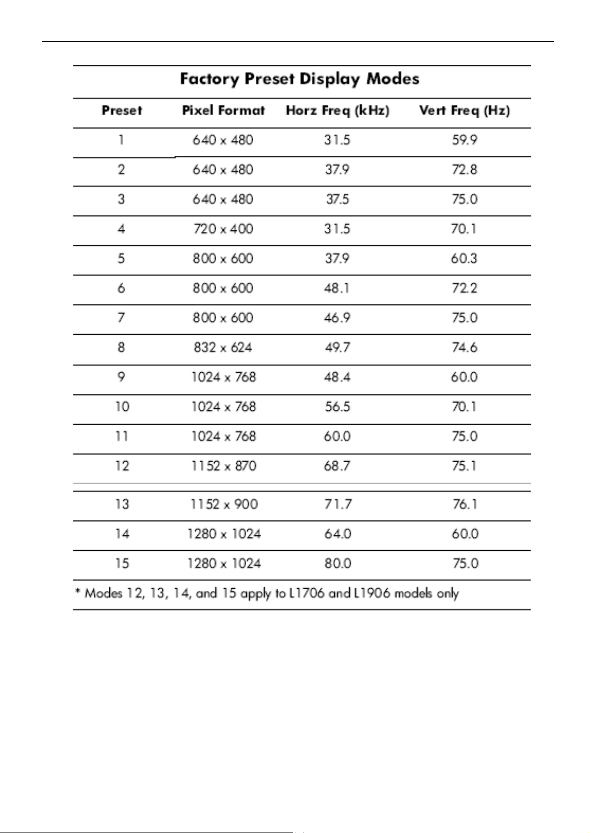
Horizontal Frequency
30- 83 kHz
TABLE OF CONTENTS
Description Page Description Page
Table Of Contents.......……..............................…........1
Revision List.…........................................……......2
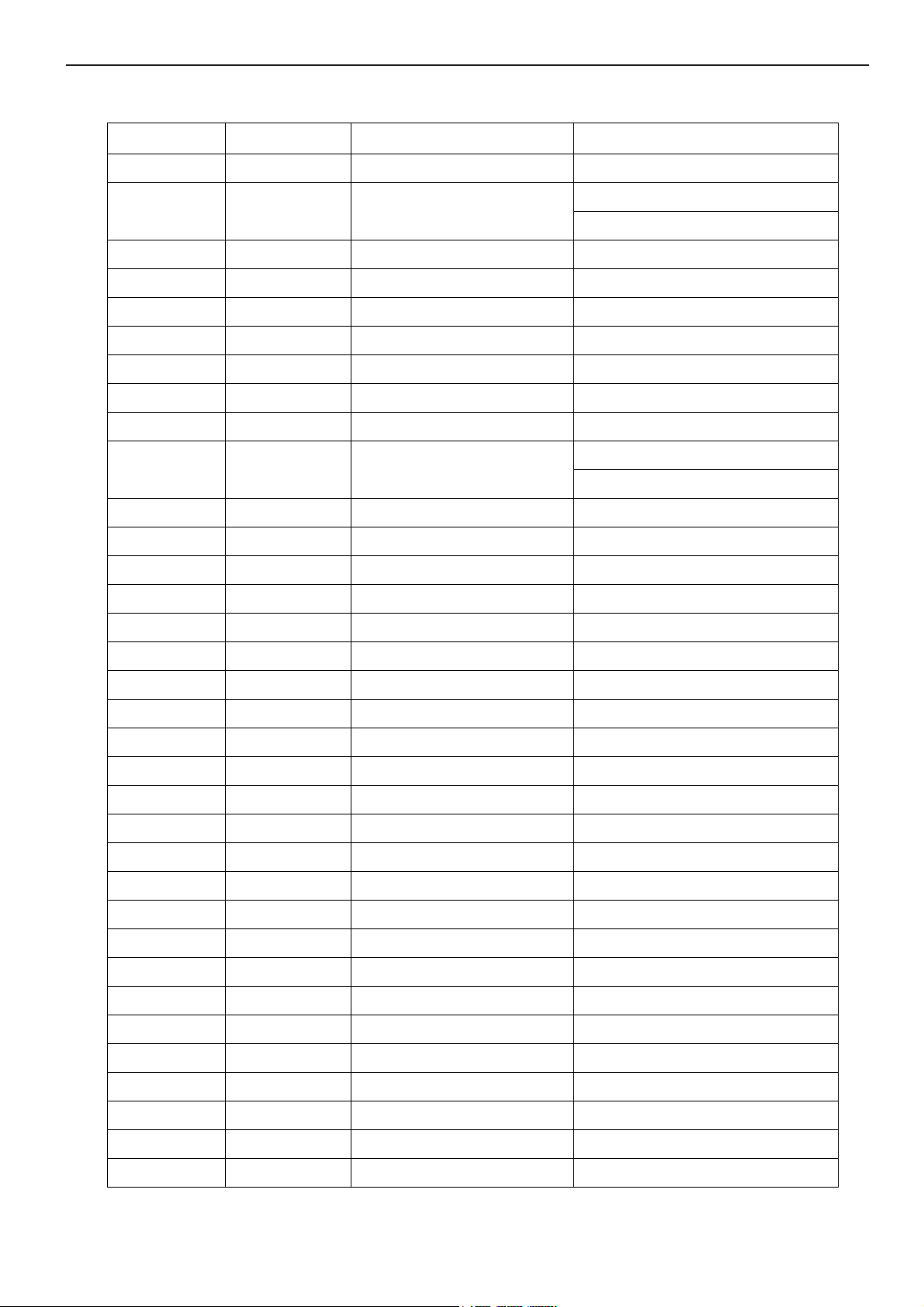
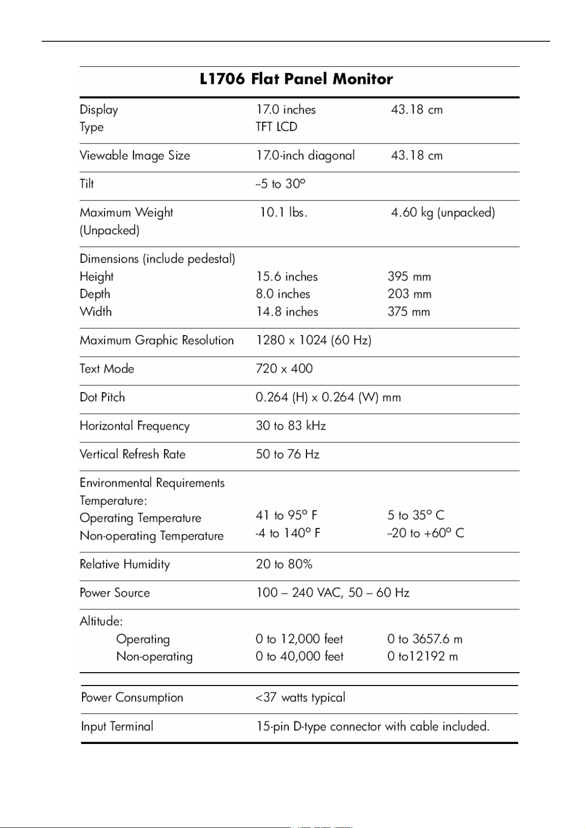
1. Monitor Specification..............................………........3
2. LCD Monitor Description…………………………….......4
3. Operation Instruction…………...............……...........5
3.1. General Instructions...........................…...........5
3.2. Control Button…………….…..............……...............5
3.3 Adjusting the Picture...........................…............6
4. Input/Output Specification............……………............7
4.1. Input Signal Connector............………….................7
4.2. Factory Preset Display Modes......…..................8
4.3. Power Supply Requirements...............................9
5. Panel Specification.....………………..................10
5.1. General Feature…….....………………..................10
5.2. Optical Characteristics………………………………11
5.3 Parameter guide line for CCFL Inverter……………..13
6. Block Diagram……...................…………................15
6.1. Monitor Exploded View…………………....….......15
6.2 Software Flow Chart……………………….……….16
6.3. Electrical Block Diagram……………..….......18
7. Schematic……………......................................20
7.1 Main Board....……….......................................20
7.2 Power Board.….……....................................24
8.PCB Layout..………….......................................26
8.1. Main Board………........................................26
8.2. Power Board….......................................28
8.3. Key Board………............….......................31
9. Maintainability……….......................................32
9.1. Equipments and Tools Requirement..............32
9.2. Trouble Shooting………..............................33
10. White-Balance, Luminance adjustment...39
11. BOM List….....................................................40
12. Different Parts List.........…….……........................52
SAFETY NOTICE
ANY PERSON ATTEMPTING TO SERVICE THIS CHASSIS MUST FAMILIARIZE HIMSELF WITH THE CHASSIS
AND BE AWARE OF THE NECESSARY SAFETY PRECAUTIONS TO BE USED WHEN SERVICING ELECTRONIC
EQUIPMENT CONTAINING HIGH VOLTAGES.
CAUTION: USE A SEPARATE ISOLATION TRANSFOMER FOR THIS UNIT WHEN SERVICING
1
Page 2
17" LCD Color Monitor HP L1706
Revision List
Version Date Revision History TPV Model Name
A00 Apr.-04-2007 first release T76CM9DKAKHPNE
A01 May.-08-2007 Add TPVDW Model in Item 12
A02 Jun.-07-2007 Add TPVDW Model in Item 12 T76SM9DKAKHPNE
A03 Jun.-19-2007 Add TPVDW Model in Item 12 T76CM9DPAKHPNE
A04 Sep.-26-2007 Add TPVDW Model in Item 12 T76GM9DBAKHFNNE
A05 Oct.-10-2007 Add TPVDW Model in Item 12 T76SM9DBAKHFNNE
A06 Oct.-16-2007 Add TPVDW Model in Item 12 T76SM9DAAKHANNE
A07 Oct.-18-2007 Add TPVDW Model in Item 12 T76CM9DBAKHFNNE
A08 Nov.-01-2007 Add TPVDW Model in Item 12 T76GM9DNAKHANNE
A09 Nov.-09-2007 Add TPVDW Model in Item 12
A10 Dec.-09-2007 Add Second Panel in Item 5 LTM170EUL31-8TM
T76GM9DKAKHPNE
T76GM9DPAKHPNE
T76SM9DKAKHPN1E
T76SM9DPAKHPNE
2
Page 3
17" LCD Color Monitor HP L1706
1. Monitor Specification
3
Page 4
17" LCD Color Monitor HP L1706
(
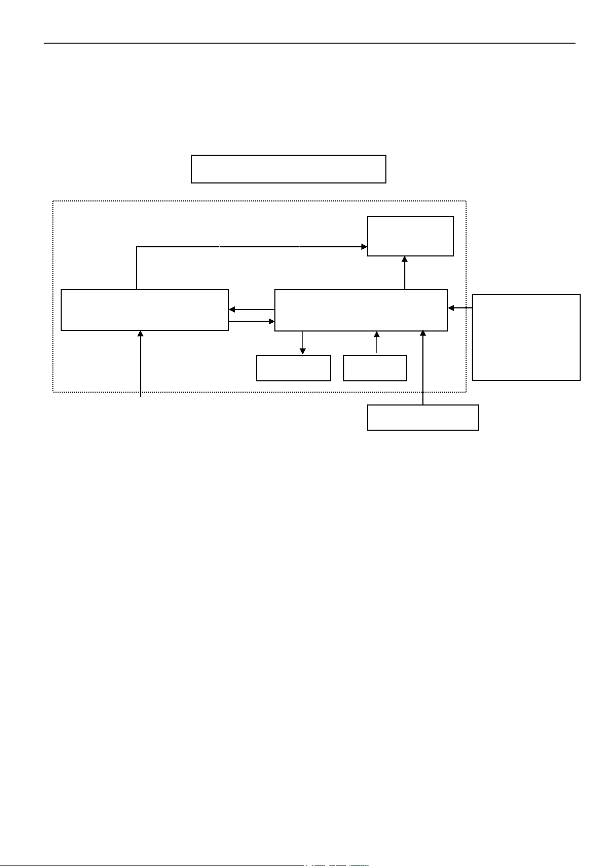
2. LCD Monitor Description
The LCD Monitor will contain main board, power board, key board and an audio board which house the flat panel
control logic, brightness control logic and DDC.
The power board will provide AC to DC Inverter voltage to drive the backlight of panel and the main board chips each
voltage.
Power Board
Include adapter and inverter)
AC-IN
110V-240
Monitor Block Diagram
CCFT Drive.
Main Board
Audio board
Key board
Flat Panel and
CCFL backlight
RS232 Connector
For white balance
adjustment in
factory mode
Video signal, DDC
HOST Computer
4
Page 5

17" LCD Color Monitor HP L1706
3. Operation Instructions
3.1 General Instructions
Press the power button to turn the monitor on or off. The other control buttons are located at front of the panel. By
changing these settings, the picture can be adjusted to your personal performance.
The power cord should be connected and insert to adaptor.
-
Connect the video cable from the monitor to the computer VGA card.
-
- Press the power button to turn on the monitor, the power indicator will light up to Green.
3.2 Control Buttons
5
Page 6
17" LCD Color Monitor HP L1706
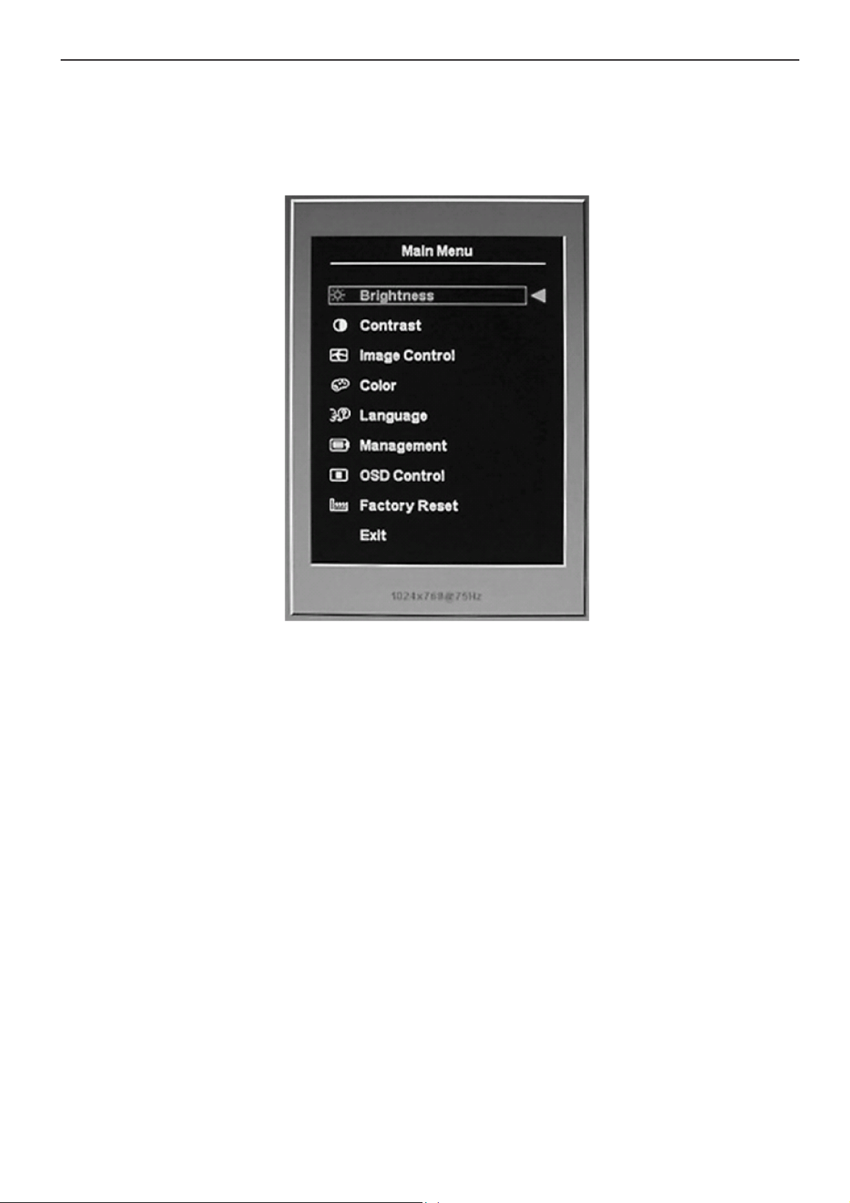
3.3 Adjust the Picture
Use the On-Screen Display (OSD) to adjust the screen image based on your viewing preferences. To access the OSD,
do the following:
1. If the monitor is not already on, press the Power switch to turn on the monitor.
2. To access the OSD Menu, press the Menu button on the monitor’s front panel.
3. To navigate through the OSD Menu, press the + (Plus) button on the monitor’s front panel to scroll up, or the –
(Minus) button to scroll in reverse.
4. To select an item from the OSD Menu, use the + or – buttons to scroll to and highlight your selection, then press the
Menu button to select that function.
5. Adjust the item using the + or – buttons on the front panel to adjust the scale.
6. After adjusting the function, select Save and Return, or Cancel if you don’t want to save the setting, then select Exit
from the Main Menu.
If the buttons remain untouched for 10 seconds while displaying a menu, new adjustments will be discarded and the
settings will revert to previous settings and exit the menu.
6
Page 7

17" LCD Color Monitor HP L1706
4. Input/Output Specification
4.1 Input Signal Connector
Pin Signal Pin Signal
1 Red Video 9 +5 V (from PC)
2 Green Video 10 Ground
3 Blue Video 11 Ground
4 Ground 12 DDC-serial Data
5 Detect Cable 13 Horizontal Sync
6 Red GND 14 Vertical Sync
7 Green GND 15 DDC-serial Clock
8 Blue GND
VGA connector layout
PIN 1
PIN 11
PIN 5
7
Page 8
17" LCD Color Monitor HP L1706
4.2 Factory Preset Display Modes
8
Page 9

17" LCD Color Monitor HP L1706
4.3 Power Supply Requirements
Parameter Range
AC Line Voltage range 100 to 240V
AC Line Frequency range 47 to 63 Hz
Peak surge Current < 55 A MAX AT 220VAC and cold starting
Leakage Current < 3.5 mA
Power Consumption
≤37W
9
Page 10
17" LCD Color Monitor HP L1706
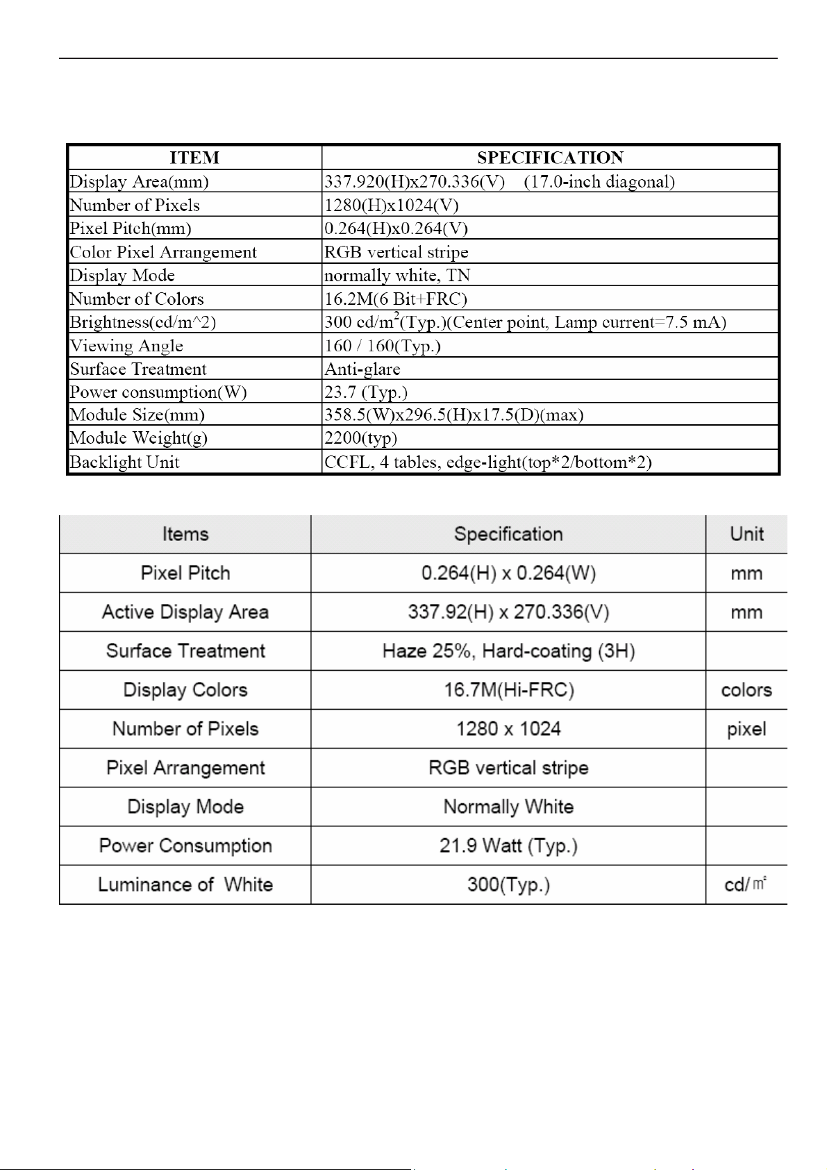
5. Panel Specification
5.1 General Feature
CLAA170EA07P
LTM170EUL31-8TM
10
Page 11
17" LCD Color Monitor HP L1706
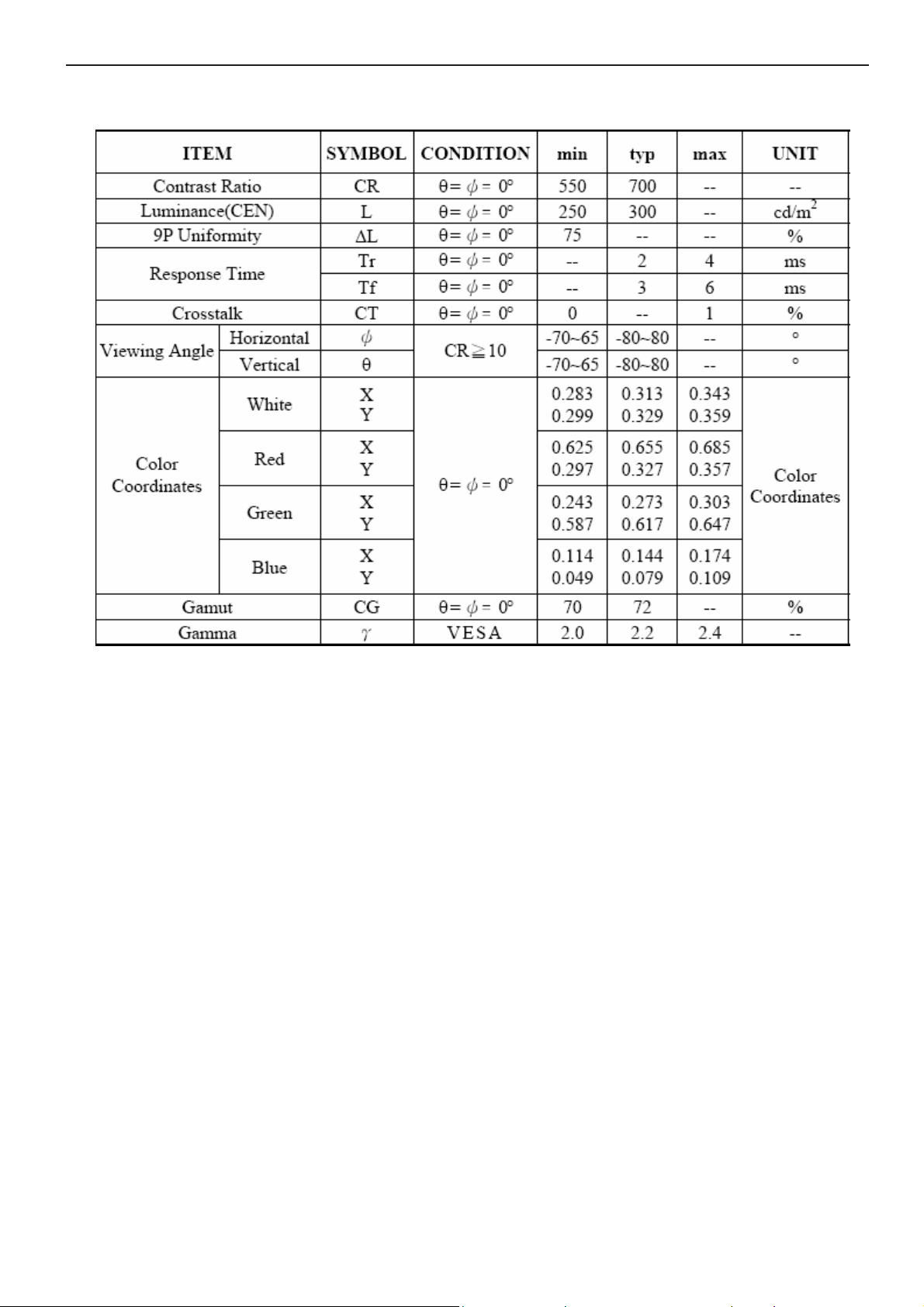
5.2 Optical Characteristics
CLAA170EA07P
11
Page 12

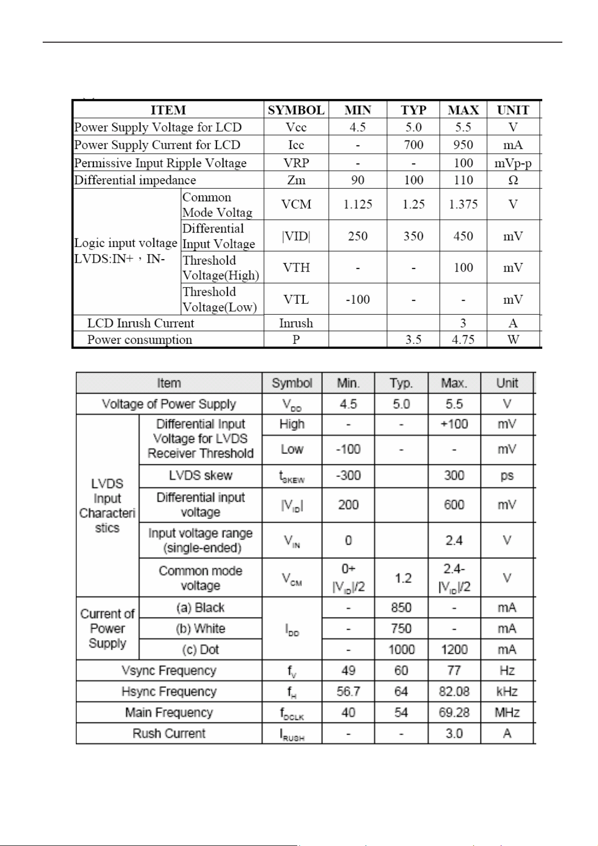
17" LCD Color Monitor HP L1706
LTM170EUL31-8TM
12
Page 13
17" LCD Color Monitor HP L1706
5.3 Parameter guide line for CCFL Inverter
TFT LCD Module:
CLAA170EA07P
LTM170EUL31-8TM
13
Page 14

17" LCD Color Monitor HP L1706
Back Light Unit:
CLAA170EA07P
LTM170EUL31-8TM
14
Page 15
17" LCD Color Monitor HP L1706
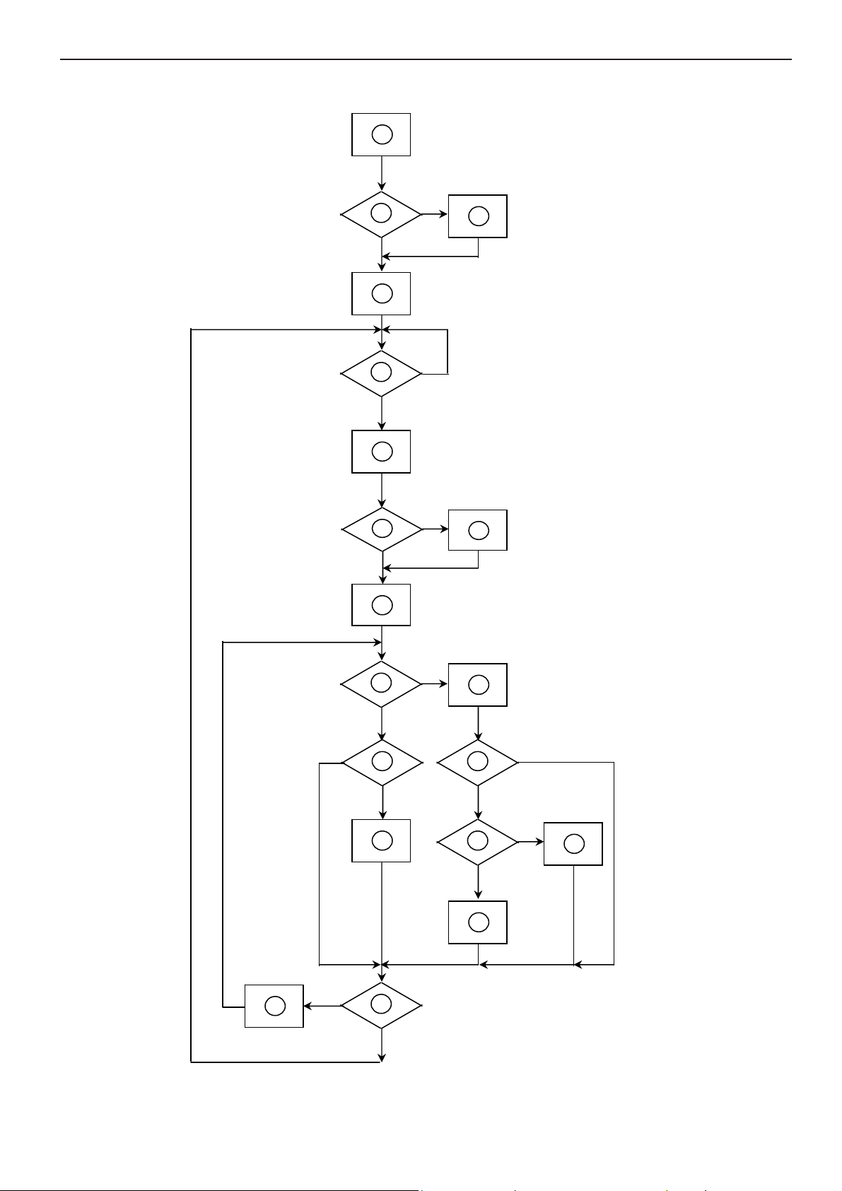
6.2 Software Flow Chart
1
Y
2
N
3
4
5
N
Y
6
N
7
8
Y
9
10
N
11
12
Y
13
N
N
Y
14
15
Y
N
16
Y
17
18
N
19
Y
16
Page 16

17" LCD Color Monitor HP L1706
REMARK:
1) MCU initialize.
2) Is the EEprom blank?
3) Program the EEprom by default values.
4) Get the PWM value of brightness from EEprom.
5) Is the power key pressed?
6) Clear all global flags.
7) Are the AUTO and SELECT keys pressed?
8) Enter factory mode.
9) Save the power key status into EEprom.
Turn on the LED and set it to green color.
Scalar initialize.
10) In standby mode?
11) Update the lifetime of back light.
12) Check the analog port, are they’re any signals coming?
13) Does the scalar send out an interrupt request?
14) Wake up the scalar.
15) Are there any signals coming from analog port?
16) Display "No connection Check Signal Cable" message. And go into standby mode after the message
disappear.
17) Program the scalar to be able to show the coming mode.
18) Process the OSD display.
19) Read the keyboard. Is the power key pressed?
17
Page 17

17" LCD Color Monitor HP L1706
Vsy
6.3 Electrical Block Diagram
6.3.1 Scalar Board
EEPROM
(U402)
EPR_SDA
EPR SCL
Panel Interface
(CN101)
Scalar TSUM16AL
(Include ADC、OSD、MCU)
(U401)
RXD
TXD
R
G
B
Hsync,
nc
DDC_SDA
DDC SCL
D-Sub Connector
(CN405)
EEPROM
(U404)
DB15_SDA
DB15 SCL
18
Page 18
17" LCD Color Monitor HP L1706
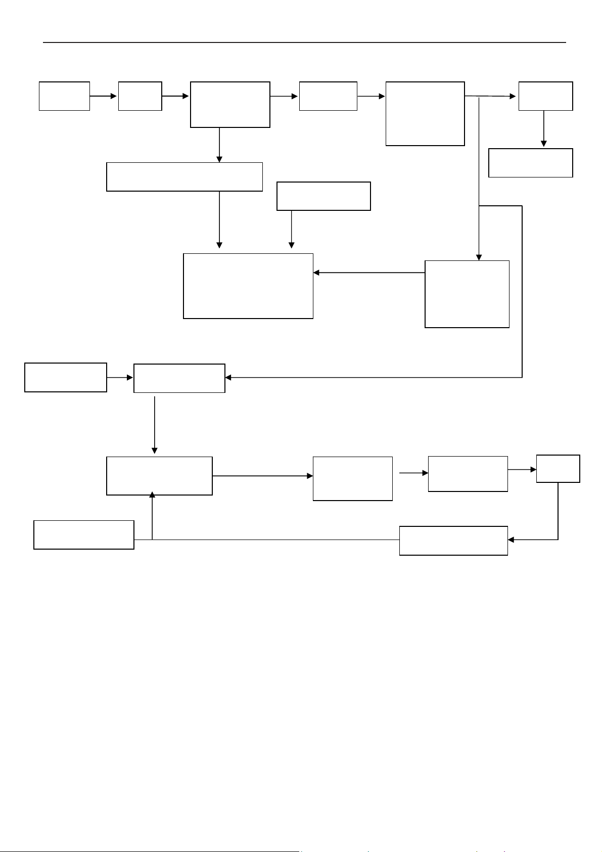
6.3.2 Inverter / Power Board
AC inlet filter
Start circuit R905; R909, R910
On/off control
Rectifier and
filter
Switching circuit
PWM control
IC&MOSFET
Start circuit
Transform
OVP circuit
Rectifier and
filter D20;
D921
Feedback
IC902;IC921
circuit
12V/5V
To main board
12V
PWM control IC
Push-pull
circuit
Dimming control
Feedback circuit
LC resonant
Lamp
19
Page 19
17" LCD Color Monitor HP L1706
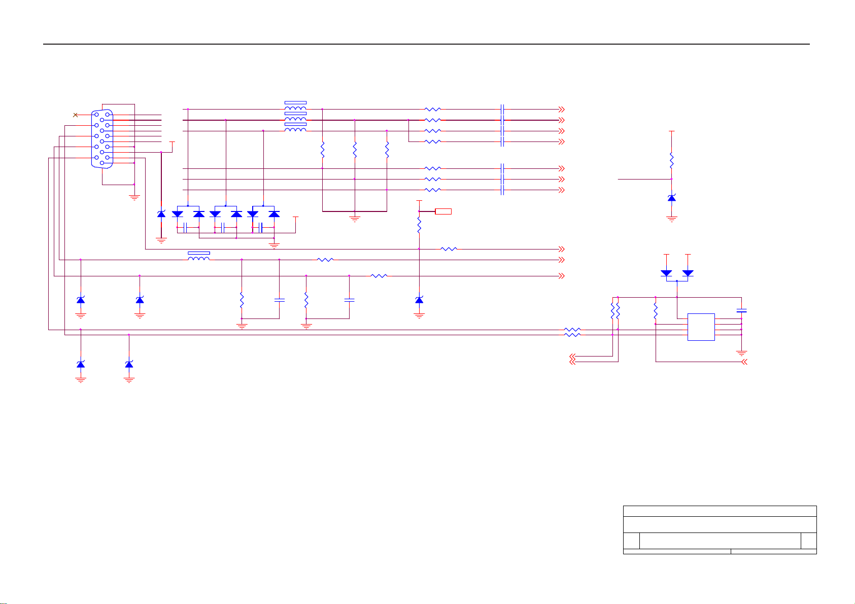
7. Schematic
7.1 Main Board
11/21 CN405 #11 change to NC
CN405
1716
11
12
13
14
15
HSI
VSI
D408
MLL5232B 5.6V
D411
MLL5232B 5.6V
DB15
1
6
2
7
3
8
4
9
5
10
RED+
REDGREEN+
GREENBLUE+
BLUE-
PC5V
D406
MLL5232B 5.6V
D409
MLL5232B 5.6V
D412
MLL5232B 5.6V
RED+
GREEN+
BLUE+
PC5V
RED-
GREEN-
BLUE-
3
D403
BAV99
C439 0. 1uF
2
VGA_CON
FB409 150 OHM
1
3
C440 0. 1uF
2
D404
BAV99
FB410 150 OHM
FB411 150 OHM
FB412 150 OHM
3
D405
BAV99
C441 0. 1uF
2
1
R448
2.2K 1/ 10W
C432 0. 047uF
C433 0. 047uF
C434 0. 047uF
C435 0. 001uF
C436 0. 047uF
C437 0. 047uF
C438 0. 047uF
SCL_VGA
SDA_VGA
RIN 2
GIN 2
BIN 2
SOG 2
GNDR 2
GNDG 2
GNDB 2
DET_VGA 2
HSYNC 2
VSYN C 2
R453 47 1/10W
R454 47 1/10W
DDCA_SDA2
DDCA_SCL2
+5V
R470
1K 1/10W
ESD_5V
D425
MLL5232B 5.6V
11/27 D407 change to BAV70(93G-64-42-P)
PC5V
+5VA
1
2
D407
BAV70
3
R451
R450
10K 1/10W
10K 1/10W
R452
10K 1/10W
U404
8
VCC
7
WP
6
SCL
5
SDA
24LC02B/SN G
VSS
A0
A1
A2
C444
0.1uF
1
2
3
4
DDC_WP 2
R434 56 1/10W
R435 56 1/10W
R436 56 1/10W
R437 470 1/10W
R439
R447 1K 1/10W
C443
220pF
75 1/10W
R438
75 1/10W
ESD_5V
1
R446 1K 1/10W
R449
C442
2.2K 1/ 10W
33pF
R440
75 1/10W
R441 100 1/10W
R442 100 1/10W
R443 100 1/10W
+5V
+5V 2, 3
R444
10K 1/10W
R445 100 1/10W
D410
MLL5232B 5.6V
20
Tit le
Size Document N umber Rev
B
Date: Sheet
715G2433-A(L1706 down size)
INPUT
14Thursday , D ecember 07, 2006
of
D
Page 20

17" LCD Color Monitor HP L1706
AVDD
VPLL VDDC
AVDD_D VI
VMPLL
8
14
VCC3.3
23
RIN1
22
GNDR1
20
GIN1
R490
R489
NC
NC
R494 10 1/10W
DDCA_SDA1
DDCA_SCL1
R495 10 1/10W
11/27 R489/R490 Delete
19
GNDG1
21
SOG1
18
BIN1
17
GNDB1
27
HSYNC1
28
VSYNC1
30
31
98
RIN0P
AVDD_DV I
AVDD_DV I
RIN0N
AVDD_MP LL
GIN0P
GIN0N
SOGIN0
BIN0P
BIN0N
HSYNC0
VSYNC0
DDCA_SD A/RS232_TX
DDCA_SCL/rs232_RX
TSUM16AL-LF PQFP-100
15
REXT
26
REFP
C401
0.1uF
25
REFM
2
37
SDO
1
38
SCZ
6
39
SCK
5
40
SDI
84
RST
XIN
96
XIN
XOU T
97
XOU T
80
XOU T
XIN
BYPASS
52
MOD E[0 ]
53
MOD E[1 ]
R416
10K 1/ 10W
C413
0.1uF
R415
+5V
R486
NC
C417
0.1uF
+5V
C418
10uF/50V
U703
RESET
3
GND
VCC
NC(MAX810STRG)
Re se t Cir cu it
C421 22pF
14.318MHz
C423 22pF
VCC3.3
+
R404
10K 1/ 10W
2
1
X401
VPLL
SST25VF010A-33-4C-SAE
8
VDD
7
HOLD#
3
WP#
VSS4SI
WP
10K 1/ 10W
R487
R491 10 1/10W
R492 10 1/ 10W
R403 390 1/10W
U402
SO
CE#
SCK
10K 1/ 10W
VDDP
56
75
VDDP
VDDP
83
34
VCTRL
VDDC
VDDC66VDDC82VDDC
LVA3P
LVA3M
LVACKP
LVACKM
LVA2P
LVA2M
LVA1P
LVA1M
LVA0P
LVA0M
LVB3P
LVB3M
LVBCKP
LVBCKM
LVB2P
LVB2M
LVB1P
LVB1M
LVB0P
LVB0M
GPIO_P23
GPIO_P22
GPIO_P15/PWM0
PWM2/GPIO_P24
GPIO_P27/PWM1
GPIO_P12
PWM1/GPIO_P25
RSTN
GPIO_P00/ SAR1
GPIO_P01/ SAR2
GPIO_P02/ SAR3
GPIO_P06
GPIO_P07
PWM0/GPIO_P26
GPIO_P13
GPIO_P14
GPIO_P16/PWM2
GPIO_P10/I2C_MCL
GPIO_P11/I 2C_MDA
NC
NC
NC
81
PA0
54
PA1
55
PA2
58
PA3
59
PA4
60
PA5
61
PA6
62
PA7
63
PA8
64
PA9
65
PB0
67
PB1
68
PB2
69
PB3
70
PB4
71
PB5
72
PB6
73
PB7
74
PB8
77
PB9
78
36
45
46
41
42
35
47
48
85
R488 100 1/10W
86
87
88
R418 100 1/10W
89
R420 100 1/10W
90
R411 100 1/10W
91
92
93
94
95
99
44
43
R424
VCC3.3
10K 1/ 10W
PA[0..9]
PA[0..9] 4
PB[0..9]
PB[0..9] 4
DDC_WP 1
C422
0.1uF
NC(10K 1/10W)
R497
Q402
MMBT3904
+5V
R496
C454
NC(0.1uF )
U403
8
VCC
7
WC
6
SCL
5
M24C04-WMN6TP
NC(10K 1/10W )
Volume
MUTE
STANDBY
1
NC
2
E1
3
E2
VSS4SDA
R405
22K 1/ 10W
R406
10K 1/ 10W
DET_VGA 1
on_PANEL 3
WP
on_BACKLIGH T 3
adj_BACKLIGH T 3
R425
10K 1/ 10W
KEY1
KEY2
NC(20K 1/10W)
POWER
R426
10K 1/ 10W
R427 100 1/10W
R428 100 1/10W
R429 100 1/10W
16
24
49
VDDP32VDDP
AVDD_PLL
AVDD_AD C
GND2GND
GND11GND29GND
GND50GND57GND76GND79GND
5
33
U401
51
Option
3.9K 1/10W
KEY2 KEY_MENU
KEY1
VCC1.83
12/07:C403/C408/C418/C450/C453/C717--Change from 67G 2151007RT(105 10UF M 50V)
to 67G 315100 7K(105 10UF M 50V)
+5V
R484
R485
NC(10K 1/10W )
R431
NC(10K 1/10W)
C425
0.1uF
VCC3.3
C429
0.1uF
R474
3.9K 1/10W
D401
UDZS3. 6B
C430
0.1uF
R475
FB401
VCC1.8
600 OHM
10uF/50V
FB403
600 OHM
10uF/50V
R430
NC(10K 1/10W )
R422 4.7K 1/ 10W
R423 4.7K 1/ 10W
R493
10K 1/10W
POWER
D402
UDZS3.6B
C403
C408
VDDPVCC3.3
D413
UDZS3.6B
+
C404
0.1uF
+
C409
0.1uF
R413
10K 1/ 10W
C405
C406
0.1uF
0.1uF
C411
C410
0.1uF
0.1uF
VCC3.3
R414
220 1/10W
Q401
PMBS3906
R421 220 1/10W
R476 1K 1/10W
R477 1K 1/10W
C412
0.1uF
0.1uF
C402
VCC3.3
FB402
600 OHM
C450
10uF/50V
AVDDVDDC
C407
+
0.1uF
VCC3.3
FB405
600 OHM
C416
0.1uF
VPLL
FB406
600 OHM
R408
10K 1/ 10W
LED_G
C428
0.1uF
C419
0.1uF
VMPLLVCC3.3
VCC3.3
C427
0.1uF
R409
220 1/ 10W
Q403
PMBS3906
FB404
600 OHM
R419 220 1/10W
LED_G
LED_A
KEY_LEFT/ AUTO
KEY_RIGH T
C426
0.1uF
10uF/50V
C453
LED_A
1
2
3
4
5
6
7
8
+
CN402
CONN
C414
0.1uF
AVDD_DVIVCC3.3
C415
0.1uF
21
Title
715G2433-A(L1706 down size)
Size Doc ument Number Rev
C
Date: Sheet
SCALER
24Thursday , December 07, 200 6
of
D
Page 21

17" LCD Color Monitor HP L1706
+5V
CN701
CONN
BL_ON
1
BL_ADJ
2
+5V
3
+5V
4
GND
5
GND
6
+
C710
47uF/25V
+5V
+5V 1,2
C709
0.1uF
11/21 CN701 change type
12/07:C710/C712/C720/C723--Change from 67G405V470 3P(105 47uF M 16V)
to 67G 315470 4K(105 47UF M 25V)
C721
0.1uF
U704 AP1117E18LA
VI3VO
2
GND
1
+
C723
47uF/25V
VCC1.8VCC3.3
VCC1.8 2
C722
0.1uF
11/21 Delete:Q702/D701/D702/R702/R703/R704/C702
ADD:U704/C721/C722/C723
+5V
R711
10K 1/10W
R706 NC
R707 4.7K 1/10W
BL_ON
BL_ADJ
C711
NC
R708
C708
1uF/25V
10K 1/10W
R710 NC
Q703
MMBT3904
R712 4.7K 1/10W
R705 4.7K 1/10W
Q701
MMBT3904
+5V
R701
1K 1/10W
11/22 C708 change to NC/R705 change to Bead(71G 59B121)
+5V
+5VA
D704
SS14
C713
0.1uF
U702
3
VIN
1
ADJ
AP1084K33LA
TO-263
VOUT
2
+
C712
47uF/25V
VCC3.3
C714
0.1uF
on_BACKLIGHT 2
Adj_BACKLI GHT 2
+3V3 +3V3
R717
10K 1/10W
R716
NC(10K 1/ 10W)
on_PANEL2
+5V
R714
10K 1/10W
R725 4.7K 1/ 10W
C718
0.1uF
VLCD
R715
R723
51K 1/10W
Q706
MMBT3904
NC(10K 1/ 10W)
10uF/50V
C715
0.1uF
C717
Q704
AO3401
+
10/11 C715 change linking
VLCD 4
+5V +3V3
R721
0 1/10W
R727
10K 1/10W
GND(TAB)
2
VOUT
TO-252
3
+
C703
NC(47uF /25V)
U701
C701
NC
NC(AI C1185-33PETR)
1
VIN
R722
NC
only for 15" panel
C704
NC
+3V3+5V
Tit le
Size Document Number Rev
B
Date: Sheet
715G2433-A(L1706 down size)
POW ER DC TO DC
34Friday , December 08, 2006
of
D
22
Page 22

17" LCD Color Monitor HP L1706
PA[0. .9]2
PB[0. .9]2
PA[0..9]
PB[0. .9]
PA0 LVA3P
PA1 LVA3M
PA2 LVACKP RXO0-LVB0M
PA3 LVACKM
PA4 LVA2P
PA5 LVA2M
PA6 LVA1P
PA7 LVA1M
PA8 LVA0P
PA9 LVA0M
LVB3PPB0
LVB3MPB1
LVBCKPPB2
LVBCKMPB3
LVB2PPB4
LVB2MPB5
LVB1PPB6
LVB1MPB7
LVB0PPB8
LVB0MPB9
LVB2M R XO2LVBCKM R XOC-
LVACKM R XEC-
CN101
RXO0+ LVB0P
RXO1+ LVB1P
RXO2+ LVB2P
RXOC+ LVBC KP
RXO3+ LVB3P
RXE0+ LVA0P
RXE1+ LVA1P
RXE2+ LVA2P
RXEC+ LVAC KP
RXE3+ LVA3P
C719
0.1uF
VLCD
C720
47uF/25V
2
4
6
8
10
12
14
16
18
20
22
24
11
13
15
17
19
21
23
1
3
5
7
9
+
CONN
RXO1-LVB1M
RXO3-LVB3M
RXE0-LVA0M
RXE1-LVA1M
RXE2-LVA2M
RXE3-LVA3M
23
Tit le
715G2433-A(L1706 down size)
Size Document Number Rev
A
Date: Sheet
PANEL INTERFACE
44Thursday , D ecem ber 07, 2006
of
D
Page 23

17" LCD Color Monitor HP L1706
7.2 Power Board
R951
3
R900
330K 1/8W
1
+
BD901
2A 600V
2
-
4
2
3
L902
L
1
4
2
3
L901
L
1
4
C909 0.47uF /250V
R901
330K 1/8W
R902
330K 1/8W
3
12
CN901
SOCKET
C902
0.001uF/125V
C901
0.001uF/125V
12
t
2.5A/250V
F901
NR901
5 ohm/8A
GND1
1
GND
HS3 D9 20
1
2
HEAT SINK
+
C907
100uF/450V
C912
0.1uF/50V
0.1uF/50V
IC901
LD7575
7
R911
100K 1/10W
穝
470PF/25V
GND2
1
GND
1
2
HEAT SINK
C916
8
HV
LD7575
N.C
RT1CS
C914
HS4 Q900
R905
10K 1/8W
OUT
GND
COMP
4
2
T901
4
C900
0.0022UF
IC902
PC123FY 2 4P
O
O
2
O
O
1
43
R909
100K 2W
C910
1500pF/1KV
D900
BA159GPT
D901
UF4003PT
+
C911
D910
LL4148WP
R912
10 1/ 8W
10K 1/10W
R913
1K 1/10W
22uF/50V
R915
D911
LL4148WP
N.C Z D901
RLZ27B
1 2
6
VCC
5
3
C913
220pF/50V
R910
7R5 1/ 8W
Q900
FQPF8N60C
1
3 2
R916
0.43 2W
N.C
IC921
Q910
1
PMBS3906
C915
0.1UF/ 25V
3 2
KIA431
12
11
10
86
7
9
12
R954
47 1/8W
R955
47 1/8W
R956
47 1/8W
R952
47 1/8W
R953
47 1/8W
47 1/8W
3
1
3
1
D922
3A/60V
C920
0.001uF/500V
D920
SBT150-10LS
2
2
N.C D921
FMW-2156
C921
0.001uF/500V
R922
470 1/4W
R925
1K 1/10W
C928
0.1uF/50V
R928
1K 1/4W
ZD921
RLZ13B
1 2
D915
R927
1K 1/10W
+
C922
680uF/25V
+
1000uF/16V
LL4148WP
蔼跋
19mm,ㄏノ13x16size
L921
+
C923
+
C924
680uF/25V
680uF/25V
C926
C932
+
1000uF/16V
ZD922
RLZ5.1B
1 2
D916
LL4148WP
R923
10K 1/10W
C929
0.1uF/ 50V
R930
1K 1/10W
RJ901
0 1/8W
3.5UH
L922
R924
3.6K 1/ 10W 1%
R929
2.4K 1/ 10W 1%
+
470UF/25V
3.5UH
C925
+
C927
470UF/25V
R926
33K 1/10W 1%
RJ902
0 1/8W
R931
10K 1/8W
CN902
CONNECTOR
1
2
3
4
5
6
7
8
9
10
F902
0 1/8W
J901
TIN COATED
+12V
ZD920
TPSMP9 1A-E3 DO-220AA
1 2
F903
0 1/8W
ON/OF F
+5V
C931
0.1uF/50V
C930
0.1uF/50V
AOC (Top Victory) Electronics Co., Ltd.
Titl e
Size Document Number Rev
Custom
Date: Sheet
audio 12V
DIM
PWPC1742HDE1(715G 1823-I)
Wednesday , Nov ember 22, 2006
+5V
J902
TIN COATED
J903
TIN COATED
J904
TIN COATED
J905
TIN COATED
J906
TIN COATED
J907
TIN COATED
J908
TIN COATED
J909
TIN COATED
J910
TIN COATED
J911
TIN COATED
of
11
A
24
Page 24

17" LCD Color Monitor HP L1706
+12V
ON/OFF
+5V
DIM
RJ801
0 1/ 8W
R803
10K 1/ 10W
N.C R806
470 1/ 8W
N.C R838
0 1/8W
R808
10K 1/ 8W
RJ802
R802
300K 1/ 8W
Q801
PMBS3904
1
N.C C801
0.1uF/ 50V
R811
0 1/8W
N.C
N.C
C803
RJ803
0 1/ 10W
R804
32
Q802
1
PMBS3904
32
R812
10K 1/ 10W
C804
2.2uF/25V
10K 1/ 8W
ZD801
RLZ5.6B
R809
1M 1/10W
RJ804
0 1/ 8W
PMBS3904
C805
1000PF/50V
R805
470 1/ 8W
Q803
1
R813
穝糤箂ン
470UF/25V
32
VCC
22 1/ 8W
R810
100K 1/ 10W
1M 1/10W
R807
C811
R814
56K 1/ 10W
C828,C829
+
C806
1UF/25V
N.C C828
0.1uF/ 50V
AM9945
10 1/ 10W
Q805
R842
R818
15 1/ 8W
C812
N.C R839
1500PF/50V
33K 1/ 8W
6
8
D1N7D1N
S1N1G1N2S2P3G2P
IC801
1
DRV1
2
VDDA
3
TIMER
4
DIM
5
ISEN
6
VSEN
7
OVPT
NC18NC2
OZ9938
1000P/50V
D2P5D2P
4
PGND
DRV2
GNDA
SSTCMP
LCT
ENA
N.C C814
CT
10 1/ 10W
16
15
14
13
12
11
10
9
R837
R819
15 1/ 8W
C813
1500PF/50V
PT801
80GL17T-36-DN
5
3
4
1 8
15K 1/ 10W
C830
100PF/50V
1
R815
R816
100K 1/ 10W
0.01uF
C808
C807
1M 1/10W
180K 1/ 10W
R820
7
C816
10PF/3KV
C817
3PF/3KV
R821
100K 1/ 10W
C818
270PF/50V
2
N.C R823
D801
BAV70
3
C831
75K 1/ 10W
100PF/50V
R822
3M / 1/ 2W
R827
3.6K 1/10W 1%
R836
1K 1/ 10W
2
3
1
D802
BAV99
R825
560 1/ 10W
CN801
2
1
33G8021-2D -U
CN802
2
1
33G8021-2D -U
17" R826 390
R817
36K 1/ 10W 1%
N.C R844 39K 1/10W
C819
0.022uF/ 50V
琌
R826
300 1/ 10W 1%
7.5mA
R841
360 1/ 10W 1%
1Mohm brust frequency:400HZ
C809
C810
560PF/50V
0.047UF/ 50V
ohm= 6.5mA
19" R826 300 ohm
=7.5mA
J811
TIN COATED
J812
TIN COATED
J818
TIN COATED
J823
TIN COATED
J814
TIN COATED
J819
TIN COATED
J815
TIN COATED
J820
TIN COATED
J816
TIN COATED
J821
TIN COATED
AOC (Top Victory) Electronics Co., Ltd.
Tit le
2. FOR 17" 4 LAMPS INVERTER
Size Document Num ber Rev
Date: Sheet
PWPC1742HDE1
Wednesday , Nov ember 22, 2006
of
11
J817
TIN COATED
J822
TIN COATED
A
C820
470UF/25V
PT802
80GL19T-36-DN
5
3
4
C822
1500PF/50V
33K 1/ 8W
R828
15 1/ 8W
N.C R840
8
S1N1G1N2S2P3G2P
N.C C815
1000P/50V
6
D1N7D1N
R829
15 1/ 8W
C823
1500PF/50V
Q806
AM9945
D2P5D2P
4
1 8
+
N.C C829
0.1uF/ 50V
25
R830
15K 1/ 10W
C832
100PF/50V
1
7
C825
10PF/3KV
R831
100K 1/ 10W
2
D803
BAV70
3
C826
3PF/3KV
C827
270PF/50V
C833
N.C R833
100PF/50V
75K 1/ 10W
R832
3M / 1/ 2W
R834
3.6K 1/10W 1%
2
1
3
D804
BAV99
R843
1K 1/ 10W
R835
560 1/ 10W
CN803
1
2
33G8021-2D-U
CN804
1
2
33G8021-2D-U
Page 25

17" LCD Color Monitor HP L1706
9. Maintainability
9.1 Equipments and Tools Requirement
1. Multi-meter.
2. Oscilloscope.
3. Pattern Generator.
4. DDC Tool with an IBM Compatible Computer.
5. Alignment Tool.
6. LCD Color Analyzer.
7. Service Manual.
8. User Manual.
32
Page 26

17" LCD Color Monitor HP L1706
9.2 Trouble Shooting
9.2.1 Main Board
No power
Press power key and look
if the picture is normal
Please reinsert and make sure
the AC of 100-240 is normal
Measure U701 PIN2=3.3V
U704 PIN2=1.8V
No power
NG
OK
OK
NG
NG
Reinsert or check the
Adapter/Inverter
Check CN701 or replace
U701 and U704
X401 oscillate waveforms
are normal
OK
Replace U401
NG
Replace X401
33
Page 27

17" LCD Color Monitor HP L1706
No picture (LED orange)
No picture
The button if under
control
NG
X401 oscillate
waveform is normal
NG
Replace X401
Measure U701 PIN2=3.3V
U704 PIN2=1.8V
OK
Check reset circuit of
U401 is normal
Replace U401
OK
OK
OK
NG
Check Correspondent
component
X401 oscillate
waveform is normal
OK
NG
NG
Replace U701, U704
Replace X401
Check HS/VS from
CN402 is normal
OK
NG
Check Correspondent
component
Replace U401
34
Page 28

17" LCD Color Monitor HP L1706
White screen
Check Correspondent
component.
White screen
Measure Q703 base
is high level?
OK
Check Q704,Q706 are
broken or CN101 solder?
NG
OK
NG
X401 oscillate
waveform is normal
OK
Check reset circuit of
U401 is normal
OK
Replace U401
NG
NG
Replace X401
Check Correspondent
component.
Replace PANEL
35
Page 29

17" LCD Color Monitor HP L1706
9.2.2 Power Board
1. No Power
No power
Check AC line volt 100V or 240V
OK
NG
Check AC line
Check the voltage of C907(+)
OK
NG
Check F901, BD901
Check start voltage for the pin3 of IC901
NG
Check R912, R913, IC901
OK
The auxiliary voltage (pin6) is between 5V-12V jumping
OK
1) Check IC901,T901
2) Check D920, D921, ZD920
3) Check IC902, IC921
Check D920 D921 ZD920…
Repeating the start voltage
OK
NG
NG (Stable)
Check D901, D900
Check IC902,IC903
Check Q910…OLP circuit
36
Page 30

17" LCD Color Monitor HP L1706
2. W/LED No Backlight
Check C811 (+) =12V
NG
OK
Check Q801/Q802/Q803
Check ON/OFF signal
OK
NG
Check Interface board
Check IC801 pin5=12V voltage
NG
Check R826/D802/R826
OK
Check the pin1/15 of IC801 if have waveforms
NG
Short Q806 S D ,if the picture normal
NG
OK
Change IC801
Connect PIN4 /PIN7of IC801 and check Q806 collector waveforms
NG
OK
Check feedback circuit
Change Q806/PT802
NG
Check connecter & lamp
37
Page 31

17" LCD Color Monitor HP L1706
9.2.3 Key Board
OSD is unstable or not working
Is Key Pad Board connecting normally?
NG
Connect Key Pad Board
Is Button Switch normally?
OK
NG
Replace Button Switch
OK
Is Key Pad Board Normally?
NG
Replace Key Pad Board
OK
Check Main Board
38
Page 32

17" LCD Color Monitor HP L1706
10. White- Balance, Luminance Adjustment
Approximately 30 minutes should be allowed for warm up before proceeding White-Balance adjustment.
1. How to do the Chroma-7120 MEM .Channel setting
A. Reference to chroma 7120 user guide
B. Use “ SC” key and “ NEXT” key to modify xyY value and use “ID” key to modify the TEXT description
Following is the procedure to do white-balance adjust
2. Setting the color temp. You want
A. 9300 color: 9300 color temp. parameter is x = 283 ±20, y = 297 ±20, Y > 180 cd/m2 ,
B. sRGB color: sRGB color temp. parameter is x = 313±20, y = 329 ±20, Y>200 cd/m2)
C. 6500K color: Don’t adjust, Custom requires.
3. Into factory mode of HP L1706
A. Press DOWN button during 2 seconds along with press Power button will activate the factory mode, then
MCU will do AUTO LEVEL automatically. Meanwhile press MENU the OSD screen will located at THE
LEFT TOP OF PANEL.
4. Bias adjustment:
Set the Contrast
Adjust the Brightness
5. Gain adjustment :
Move cursor to “-F-” and press MENU key
A. Adjust 9300k color-temperature
1. Switch the Chroma-7120 to 9300k channel.
2. The chroma 7120 will show x = 283±20, y = 297 ±20, Y>180 cd/m2
3. Switch the chroma-720 to RGB MODE (with press “MODE” button to change )
4. Adjust the RED of color 9300K on factory window until chroma 7120 indicator reached the value R=100
5. Adjust the GREEN of color 9300K on factory window until chroma 7120 indicator reached the value G=100
6. Adjust the BLUE of color 9300K on factory window until chroma 7120 indicator reached the value B=100
7. Repeat above procedure ( item 4,5,6) until chroma 7120 RGB value meet the tolerance =100±2
B. Adjust sRGB color-temperature
1. Switch the chroma-7120 to sRGB channel.
2. The chroma 7120 will show x = 313 ±20, y = 329 ±20, Y = 210 ±20 cd/m2
3. Switch the chroma 7120 l to RGB MODE ( with press “MODE” button to change )
to 80
to 90.
4. Adjust the RED of color sRGB on factory window until chroma 7120 indicator reached the value R=100
5. Adjust the GREEN of color sRGB on factory window until chroma 7120 indicator reached the value G=100
6. Adjust the BLUE of color sRGB on factory window until chroma 7120 indicator reached the value B=100
7. Repeat above procedure ( item 4,5,6) until chroma 7120 RGB value meet the tolerance =100±2
C. Press reset key and Turn the Power-button “off to on” to quit from factory mode.
39
Page 33

17" LCD Color Monitor HP L1706
11. BOM List
T76CM9DKAKHPNE
Location Part No. Description
CBPC6CM9HPH2 MAIN BOARD FOR 17
KEPC6HB3 KEY BOARD FOR POWER
KEPC980KHP4P KEY BOARD
PWPC742CH2PH POWER BOARD
33G4856 EY L LOGO PLATE
33G4889 EY L STAND CAP
34G1568 EY B REAR COVER
40G 58169016A TCO03 LABEL
41G780069094B QSG
44G3760 1 EPS(L)
44G3760 2 EPS(R)
52G 1185 MIDDLE TAPE
52G 1186 SMALL TAPE
52G6022 1500 SMALL TAPE
E089B 89G 728CAAE02 SIGNAL CABLE
E089A 89G402A19N IS AC POWER CABLE
95G8014 8 30 HARNESS 160MM 8P-8P
E095 95G8018 3QE07 WIRE HARNESS
M1G 130 5225 CR3 SCREW
M1G 340 8225 CR3 SCREW 4*8mm
M1G1730 6128 CR3 SCREW M3x6
M1G1730 6128 CR3 SCREW M3x6
M1G1740 6128 CR3 SCREW
M1G2940 10225 CR3 SCREW
P1G3030 5 47 CR3 SCREW
Q1G 330 6120 SCREW M3X6mm
Q1G 330 6120 SCREW M3X6mm
Q1G 330 6120 SCREW M3X6mm
705G780KF34 36 BEZEL ASS'Y
705G780KP34 10 STAND ASS'Y
705GH7K0 87001 AC SOCKET ASS'Y
750GLC70A7P13Z000H PANEL CLAA170EA07P 000
H15G8162 A 3 MAIN FRAME
H40G 170690 2E RATING LABEL
H40G 17N690 5A RATING LABEL
H40G581H690 2A CARTON LABEL
H41G160069033E DOC KIT FOR NA(391904-D
40
Page 34

17" LCD Color Monitor HP L1706
H41G780069099C SCREEN FLY (311618-007
H41G7800690B12 RTF CARD(407430-004)
H44G3760690 3D CARTON FOR L1706(385898
H45G 87 1 2H R PE BAG FOR MONITOR
H45G 87 4 H R PE BAG FOR BASE
H52G6025 16 14 INSULATE SHEET
CN701 33G3802 6 6065 WAFER
CN402 33G3802 8H 6176 WAFER 8P RIGHT ANGLE PI
CN101 33G8043 24 H6176 WAFER
40G 457624 1B CPU LABEL
40G 45762412B CBPC LABEL
C403 67G 3151007KV6366 ELCAP 10UF +-20% 50V 10
C408 67G 3151007KV6366 ELCAP 10UF +-20% 50V 10
C418 67G 3151007KV6366 ELCAP 10UF +-20% 50V 10
C450 67G 3151007KV6366 ELCAP 10UF +-20% 50V 10
C453 67G 3151007KV6366 ELCAP 10UF +-20% 50V 10
C717 67G 3151007KV6366 ELCAP 10UF +-20% 50V 10
C710 67G 3154704KV6366 ELCAP 47UF +-20% 25V 10
C712 67G 3154704KV6366 ELCAP 47UF +-20% 25V 10
C720 67G 3154704KV6366 ELCAP 47UF +-20% 25V 10
C723 67G 3154704KV6366 ELCAP 47UF +-20% 25V 10
CN405 88G 35315F H D-SUB 15PIN
X401 93G 22 53 14.31818MHZ HC-49US
U401 56G 562105 TSUM16AL-LF PQFP-100
U702 56G 563 21 AP1084K33LA
U704 56G 56327A AP1117E18LA SOT223-3L A
U403 56G1133 32 IC M24C04-WMN6TP SO8
U404 56G1133 34 M24C02-WMN6TP
U402 56G1133 74 SST25VF010A-33-4C-SAE
Q402 57G 417 4 PMBS3904/PHILIPS-SMT(04
Q701 57G 417 4 PMBS3904/PHILIPS-SMT(04
Q703 57G 417 4 PMBS3904/PHILIPS-SMT(04
Q706 57G 417 4 PMBS3904/PHILIPS-SMT(04
Q401 57G 417 6 PMBS3906/PHILIPS-SMT(06
Q403 57G 417 6 PMBS3906/PHILIPS-SMT(06
Q704 57G 763 1 AO3401L SOT23 BY AOS(A1
R721 61G0603000 6857 RST CHIPR 0 OHM +-5% 1/
R491 61G0603100 6857 RST CHIPR 10 OHM +-5% 1
R492 61G0603100 6857 RST CHIPR 10 OHM +-5% 1
R494 61G0603100 6857 RST CHIPR 10 OHM +-5% 1
41
Page 35

17" LCD Color Monitor HP L1706
R495 61G0603100 6857 RST CHIPR 10 OHM +-5% 1
R411 61G0603101 6857 RST CHIPR 100 OHM +-5%
R418 61G0603101 6857 RST CHIPR 100 OHM +-5%
R420 61G0603101 6857 RST CHIPR 100 OHM +-5%
R427 61G0603101 6857 RST CHIPR 100 OHM +-5%
R428 61G0603101 6857 RST CHIPR 100 OHM +-5%
R429 61G0603101 6857 RST CHIPR 100 OHM +-5%
R441 61G0603101 6857 RST CHIPR 100 OHM +-5%
R442 61G0603101 6857 RST CHIPR 100 OHM +-5%
R443 61G0603101 6857 RST CHIPR 100 OHM +-5%
R445 61G0603101 6857 RST CHIPR 100 OHM +-5%
R488 61G0603101 6857 RST CHIPR 100 OHM +-5%
R446 61G0603102 6857 RST CHIPR 1KOHM +-5% 1/
R447 61G0603102 6857 RST CHIPR 1KOHM +-5% 1/
R470 61G0603102 6857 RST CHIPR 1KOHM +-5% 1/
R476 61G0603102 6857 RST CHIPR 1KOHM +-5% 1/
R477 61G0603102 6857 RST CHIPR 1KOHM +-5% 1/
R701 61G0603102 6857 RST CHIPR 1KOHM +-5% 1/
R404 61G0603103 6857 RST CHIPR 10KOHM +-5% 1
R406 61G0603103 6857 RST CHIPR 10KOHM +-5% 1
R408 61G0603103 6857 RST CHIPR 10KOHM +-5% 1
R413 61G0603103 6857 RST CHIPR 10KOHM +-5% 1
R415 61G0603103 6857 RST CHIPR 10KOHM +-5% 1
R416 61G0603103 6857 RST CHIPR 10KOHM +-5% 1
R424 61G0603103 6857 RST CHIPR 10KOHM +-5% 1
R425 61G0603103 6857 RST CHIPR 10KOHM +-5% 1
R426 61G0603103 6857 RST CHIPR 10KOHM +-5% 1
R444 61G0603103 6857 RST CHIPR 10KOHM +-5% 1
R450 61G0603103 6857 RST CHIPR 10KOHM +-5% 1
R451 61G0603103 6857 RST CHIPR 10KOHM +-5% 1
R452 61G0603103 6857 RST CHIPR 10KOHM +-5% 1
R487 61G0603103 6857 RST CHIPR 10KOHM +-5% 1
R493 61G0603103 6857 RST CHIPR 10KOHM +-5% 1
R708 61G0603103 6857 RST CHIPR 10KOHM +-5% 1
R711 61G0603103 6857 RST CHIPR 10KOHM +-5% 1
R714 61G0603103 6857 RST CHIPR 10KOHM +-5% 1
R717 61G0603103 6857 RST CHIPR 10KOHM +-5% 1
R727 61G0603103 6857 RST CHIPR 10KOHM +-5% 1
R409 61G0603221 6857 RST CHIPR 220 OHM +-5%
R414 61G0603221 6857 RST CHIPR 220 OHM +-5%
42
Page 36

17" LCD Color Monitor HP L1706
R419 61G0603221 6857 RST CHIPR 220 OHM +-5%
R421 61G0603221 6857 RST CHIPR 220 OHM +-5%
R448 61G0603222 6857 RST CHIPR 2.2KOHM +-5%
R449 61G0603222 6857 RST CHIPR 2.2KOHM +-5%
R405 61G0603223 6857 RST CHIPR 22KOHM +-5% 1
R403 61G0603390 0F6857 RST CHIPR 390 OHM +-1%
R474 61G0603392 6857 RST CHIPR 3.9KOHM +-5%
R475 61G0603392 6857 RST CHIPR 3.9KOHM +-5%
R453 61G0603470 6857 RST CHIPR 47 OHM +-5% 1
R454 61G0603470 6857 RST CHIPR 47 OHM +-5% 1
R437 61G0603471 6857 RST CHIPR 470 OHM +-5%
R422 61G0603472 6857 RST CHIPR 4.7KOHM +-5%
R423 61G0603472 6857 RST CHIPR 4.7KOHM +-5%
R707 61G0603472 6857 RST CHIPR 4.7KOHM +-5%
R712 61G0603472 6857 RST CHIPR 4.7KOHM +-5%
R725 61G0603472 6857 RST CHIPR 4.7KOHM +-5%
R723 61G0603513 6857 RST CHIPR 51KOHM +-5% 1
R434 61G0603560 6857 RST CHIPR 56 OHM +-5% 1
R435 61G0603560 6857 RST CHIPR 56 OHM +-5% 1
R436 61G0603560 6857 RST CHIPR 56 OHM +-5% 1
R438 61G0603750 6857 RST CHIPR 75 OHM +-5% 1
R439 61G0603750 6857 RST CHIPR 75 OHM +-5% 1
R440 61G0603750 6857 RST CHIPR 75 OHM +-5% 1
C435 65G0603102 326857 1000PF +-10% 50V X7R
C401 65G0603104 326029 CHIP 0.1UF 50V X7R
C402 65G0603104 326029 CHIP 0.1UF 50V X7R
C404 65G0603104 326029 CHIP 0.1UF 50V X7R
C405 65G0603104 326029 CHIP 0.1UF 50V X7R
C406 65G0603104 326029 CHIP 0.1UF 50V X7R
C407 65G0603104 326029 CHIP 0.1UF 50V X7R
C409 65G0603104 326029 CHIP 0.1UF 50V X7R
C410 65G0603104 326029 CHIP 0.1UF 50V X7R
C411 65G0603104 326029 CHIP 0.1UF 50V X7R
C412 65G0603104 326029 CHIP 0.1UF 50V X7R
C413 65G0603104 326029 CHIP 0.1UF 50V X7R
C414 65G0603104 326029 CHIP 0.1UF 50V X7R
C415 65G0603104 326029 CHIP 0.1UF 50V X7R
C416 65G0603104 326029 CHIP 0.1UF 50V X7R
C417 65G0603104 326029 CHIP 0.1UF 50V X7R
C419 65G0603104 326029 CHIP 0.1UF 50V X7R
43
Page 37

17" LCD Color Monitor HP L1706
C422 65G0603104 326029 CHIP 0.1UF 50V X7R
C426 65G0603104 326029 CHIP 0.1UF 50V X7R
C427 65G0603104 326029 CHIP 0.1UF 50V X7R
C428 65G0603104 326029 CHIP 0.1UF 50V X7R
C429 65G0603104 326029 CHIP 0.1UF 50V X7R
C430 65G0603104 326029 CHIP 0.1UF 50V X7R
C439 65G0603104 326029 CHIP 0.1UF 50V X7R
C440 65G0603104 326029 CHIP 0.1UF 50V X7R
C441 65G0603104 326029 CHIP 0.1UF 50V X7R
C444 65G0603104 326029 CHIP 0.1UF 50V X7R
C709 65G0603104 326029 CHIP 0.1UF 50V X7R
C713 65G0603104 326029 CHIP 0.1UF 50V X7R
C714 65G0603104 326029 CHIP 0.1UF 50V X7R
C715 65G0603104 326029 CHIP 0.1UF 50V X7R
C718 65G0603104 326029 CHIP 0.1UF 50V X7R
C719 65G0603104 326029 CHIP 0.1UF 50V X7R
C721 65G0603104 326029 CHIP 0.1UF 50V X7R
C722 65G0603104 326029 CHIP 0.1UF 50V X7R
C421 65G0603220 316857 CHIP 22PF 50V NPO
C423 65G0603220 316857 CHIP 22PF 50V NPO
C443 65G0603221 326857 CHIP 220PF 50V X7R
C425 65G0603224 126805 CHIP 0.22UF 50V X7R
C442 65G0603330 316857 33PF+-5% 50V NPO
C432 65G0603473 326805 CHIP 0.047UF 50V X7R
C433 65G0603473 326805 CHIP 0.047UF 50V X7R
C434 65G0603473 326805 CHIP 0.047UF 50V X7R
C436 65G0603473 326805 CHIP 0.047UF 50V X7R
C437 65G0603473 326805 CHIP 0.047UF 50V X7R
C438 65G0603473 326805 CHIP 0.047UF 50V X7R
FB409 71G 56G151 A6888 TB160808G151
FB401 71G 56Z601 6457 CHIP BEAD 600 OHM 0805
FB402 71G 56Z601 6457 CHIP BEAD 600 OHM 0805
FB403 71G 56Z601 6457 CHIP BEAD 600 OHM 0805
FB404 71G 56Z601 6457 CHIP BEAD 600 OHM 0805
FB405 71G 56Z601 6457 CHIP BEAD 600 OHM 0805
FB406 71G 56Z601 6457 CHIP BEAD 600 OHM 0805
R705 71G 59B121 6888 TB160808B
FB410 71G 59C300 30 OHM BEAD
FB411 71G 59C300 30 OHM BEAD
FB412 71G 59C300 30 OHM BEAD
44
Page 38

17" LCD Color Monitor HP L1706
D406 93G 39149 MLL5232B BY FULL POWER
D408 93G 39149 MLL5232B BY FULL POWER
D409 93G 39149 MLL5232B BY FULL POWER
D410 93G 39149 MLL5232B BY FULL POWER
D411 93G 39149 MLL5232B BY FULL POWER
D412 93G 39149 MLL5232B BY FULL POWER
D425 93G 39149 MLL5232B BY FULL POWER
D407 93G 64 42 P BAV70 SOT-23
D403 93G 6433P BAV99
D404 93G 6433P BAV99
D405 93G 6433P BAV99
D401 93G 39S 94 T ZENER DIODE UDZS3.6B SC
D402 93G 39S 94 T ZENER DIODE UDZS3.6B SC
D413 93G 39S 94 T ZENER DIODE UDZS3.6B SC
D704 93G1004 3 SS14
715G2433 2 6F2I MAIN BOARD PCB
SW1 77G 600 1GCJ TACT SWITCH TSPB-2
DP1 81G 12 1F GP6356 LED
CN201 95G8014 45146078 HARNESS
C001 65G0603102 326857 1000PF +-10% 50V X7R
C002 65G0603102 326857 1000PF +-10% 50V X7R
C003 65G0603102 326857 1000PF +-10% 50V X7R
715G1532 3 P6F2I KEPC PCB
CN102 33G3802 4H 6176 WAFER 4P RIGHT ANGLE
CN101 33G8027 8 H6176 WAFER 8P 2.0mm DIP DUAL
SW2 77G 600 1GCJ TACT SWITCH TSPB-2
SW3 77G 600 1GCJ TACT SWITCH TSPB-2
SW4 77G 600 1GCJ TACT SWITCH TSPB-2
715G1532 3 K6F2I KEPC PCB
L901 S73G17476V FIL TER
CN801 33G8021 2E U WAFER
CN802 33G8021 2E U WAFER
CN803 33G8021 2E U WAFER
CN804 33G8021 2E U WAFER
CN901 33G8029 5A 6176 WAFER
40G 45762420A ID LABEL
IC902 56G 139 3A PC123Y22FZOF
NR901 61G 58080 WT6872 RST NTCR 8 OHM
R916 61G152M438 646W56 RST MOFR 0.43 OHM +-5%
C909 63G107K474 US6377 0.47UF +-10%
45
Page 39

17" LCD Color Monitor HP L1706
C816 65G 3J1206ET H 12PF 5% SL 3KV TDK
C825 65G 3J1206ET H 12PF 5% SL 3KV TDK
C817 65G 3J3096ET H 3PF,J,3KV,Z5P
C826 65G 3J3096ET H 3PF,J,3KV,Z5P
C901 65G305M1022E26W29 1000P 400VAC/250VAC
C902 65G305M1022E26W29 1000P 400VAC/250VAC
C900 65G306M2222BP6W29 2200PF +-20% 400VAC
C905 65G306M3322BP6W29 3300PF 20%
C811 67G215D4714KV6366 ELCAP 470UF +-20% 25V 1
C820 67G215D4714KV6366 ELCAP 470UF +-20% 25V 1
C925 67G215D4714KV6366 ELCAP 470UF +-20% 25V 1
C922 67G215D6814KV6366
C923 67G215D6814KV6366
C924 67G215D6814KV6366
C926 67G215S1023KV6366 ELCAP 1000UF +-20% 16V
C927 67G215S4713KV6366 ELCAP 470UF +-20% 16V 1
C932 67G215S4713KV6366 ELCAP 470UF +-20% 16V 1
C907 67G315Z12115K6366 ELCAP 120UF +-20% 450V
L902 73G 174 65 H LINE FILTER
L921 73G 253 91 H CHOKE COIL
L922 73G 253 91 H CHOKE COIL
T901 80GL17T 33 N POWER X'FMR
PT801 80GL17T 36 H XFMR FOR INVERTER DADON
PT802 80GL17T 36 H XFMR FOR INVERTER DADON
BD901 93G 50460502 KBP206G
D900 93G1100 1052T BA159G
D922 93G3010 1 31DQ10FC
ELCAP 105℃ 680UF M 25V
ELCAP 105℃ 680UF M 25V
ELCAP 105℃ 680UF M 25V
CN902 95G8014 12E026816 WIRE HARNESS
705GH9K0 57001 Q901 ASS'Y
705GH9K0 93002 D920 ASS'Y
Q51G 6 4508 RTV
705G 909 11 06 R909 ASS'Y
705GH7K0 34001 SHIELDING
IC901 56G 379 61 LD7575PS SOP-8
IC801 56G 608 10 OZ9938GN
Q801 57G 417 4 PMBS3904/PHILIPS-SMT(04
Q802 57G 417 4 PMBS3904/PHILIPS-SMT(04
Q803 57G 417 4 PMBS3904/PHILIPS-SMT(04
Q805 57G 763 14 AM9945N
Q806 57G 763 14 AM9945N
46
Page 40

17" LCD Color Monitor HP L1706
R837 61G0805100 6857 RST CHIPR 10 OHM +-5% 1
R842 61G0805100 6857 RST CHIPR 10 OHM +-5% 1
R911 61G0805100 3F6857 RST CHIPR 100KOHM +-1%
R927 61G0805101 6857 RST CHIPR 100 OHM +-5%
R930 61G0805101 6857 RST CHIPR 100 OHM +-5%
R836 61G0805102 6857 RST CHIPR 1KOHM +-5% 1/
R843 61G0805102 6857 RST CHIPR 1KOHM +-5% 1/
R913 61G0805102 6857 RST CHIPR 1KOHM +-5% 1/
R925 61G0805102 6857 RST CHIPR 1KOHM +-5% 1/
R928 61G0805102 6857 RST CHIPR 1KOHM +-5% 1/
R803 61G0805103 6857 RST CHIPR 10KOHM +-5% 1
R812 61G0805103 6857 RST CHIPR 10KOHM +-5% 1
R915 61G0805103 6857 RST CHIPR 10KOHM +-5% 1
R923 61G0805103 6857 RST CHIPR 10KOHM +-5% 1
R810 61G0805104 6857 RST CHIPR 100KOHM +-5%
R815 61G0805104 6857 RST CHIPR 100KOHM +-5%
R813 61G0805105 6857 RST CHIPR 1MOHM +-5% 1/
R816 61G0805105 6857 RST CHIPR 1MOHM +-5% 1/
R821 61G0805110 3F6857 RST CHIPR 110KOHM +-1%
R831 61G0805110 3F6857 RST CHIPR 110KOHM +-1%
R820 61G0805150 2F6857 RST CHIPR 15KOHM +-1% 1
R830 61G0805150 2F6857 RST CHIPR 15KOHM +-1% 1
R824 61G0805184 6857 RST CHIPR 180KOHM +-5%
R929 61G0805240 1F6857 RST CHIPR 2.4KOHM +-1%
R826 61G0805301 6857 RST CHIPR 300 OHM +-5%
R827 61G0805330 1F6857 RST CHIPR 3.3KOHM +-1%
R834 61G0805330 1F6857 RST CHIPR 3.3KOHM +-1%
R926 61G0805330 2F6857 RST CHIPR 33KOHM +-1% 1
R841 61G0805360 0F6857 RST CHIPR 360 OHM +-1%
R924 61G0805360 1F6857 RST CHIPR 3.6KOHM +-1%
R817 61G0805390 2F6857 RST CHIPR 39KOHM +-1% 1
R825 61G0805561 6857 RST CHIPR 560 OHM +-5%
R835 61G0805561 6857 RST CHIPR 560 OHM +-5%
R814 61G0805623 6857 RST CHIPR 62KOHM +-5% 1
C835 61G1206000 6857 RST CHIPR 0 OHM +-5% 1/
C836 61G1206000 6857 RST CHIPR 0 OHM +-5% 1/
C837 61G1206000 6857 RST CHIPR 0 OHM +-5% 1/
C838 61G1206000 6857 RST CHIPR 0 OHM +-5% 1/
F902 61G1206000 6857 RST CHIPR 0 OHM +-5% 1/
F903 61G1206000 6857 RST CHIPR 0 OHM +-5% 1/
47
Page 41

17" LCD Color Monitor HP L1706
RJ801 61G1206000 6857 RST CHIPR 0 OHM +-5% 1/
RJ901 61G1206000 6857 RST CHIPR 0 OHM +-5% 1/
RJ902 61G1206000 6857 RST CHIPR 0 OHM +-5% 1/
R912 61G1206100 6857 RST CHIPR 10 OHM +-5% 1
R804 61G1206103 6857 RST CHIPR 10KOHM +-5% 1
R808 61G1206103 6857 RST CHIPR 10KOHM +-5% 1
R905 61G1206103 6857 RST CHIPR 10KOHM +-5% 1
R931 61G1206103 6857 RST CHIPR 10KOHM +-5% 1
R818 61G1206150 6857 RST CHIPR 15 OHM +-5% 1
R819 61G1206150 6857 RST CHIPR 15 OHM +-5% 1
R828 61G1206150 6857 RST CHIPR 15 OHM +-5% 1
R829 61G1206150 6857 RST CHIPR 15 OHM +-5% 1
R807 61G1206220 6857 RST CHIPR 22 OHM +-5% 1
R802 61G1206304 6857 RST CHIPR 300KOHM +-5%
R900 61G1206334 6857 RST CHIPR 330KOHM +-5%
R901 61G1206334 6857 RST CHIPR 330KOHM +-5%
R902 61G1206334 6857 RST CHIPR 330KOHM +-5%
R951 61G1206470 6857 RST CHIPR 47 OHM +-5% 1
R952 61G1206470 6857 RST CHIPR 47 OHM +-5% 1
R954 61G1206470 6857 RST CHIPR 47 OHM +-5% 1
R955 61G1206470 6857 RST CHIPR 47 OHM +-5% 1
R805 61G1206471 6857 RST CHIPR 470 OHM +-5%
R910 61G1206759 6857 RST CHIPR 7.5 OHM +-5%
C833 65G0805101 316029 CHIP 100PF 50V NPD 0805
C805 65G0805102 326857 CHIP 1000P 50VX7R 0805
C807 65G0805103 326029 10NF/50V/0805/X7R
C912 65G0805104 326805 CHIP 0.1U 50V X7R
C916 65G0805104 326805 CHIP 0.1U 50V X7R
C928 65G0805104 326805 CHIP 0.1U 50V X7R
C929 65G0805104 326805 CHIP 0.1U 50V X7R
C930 65G0805104 326805 CHIP 0.1U 50V X7R
C931 65G0805104 326805 CHIP 0.1U 50V X7R
C806 65G0805105 226029 CHIP 1UF 25V X7R 0805
C812 65G0805152 326805 CHIP 1500PF 50V X7R 080
C813 65G0805152 326805 CHIP 1500PF 50V X7R 080
C822 65G0805152 326805 CHIP 1500PF 50V X7R 080
C823 65G0805152 326805 CHIP 1500PF 50V X7R 080
C913 65G0805221 326857 CHIP 220PF 50V X7R 0805
C819 65G0805223 226029 CHIP 0.022UF 25V X7R 08
C804 65G0805225 126029 CHIP 2.2UF 15V X7R 0805
48
Page 42

17" LCD Color Monitor HP L1706
C818 65G0805271 316029 MLCC 0805 270PF J 50V N
C827 65G0805271 316029 MLCC 0805 270PF J 50V N
C831 65G0805271 316029 MLCC 0805 270PF J 50V N
C830 65G0805470 316805 47PF/50V/0805/NPO
C832 65G0805470 316805 47PF/50V/0805/NPO
C914 65G0805471 226029 470PF 25V
C810 65G0805471 316857 CHIP 470PF 50V NPO
C809 65G0805473 326029 CHIP 0.047UF 50V X7R
D801 93G 64 42 PP BAV70 SOT-23
D803 93G 64 42 PP BAV70 SOT-23
D910 93G 64 44 S LL4148WP
D915 93G 64 44 S LL4148WP
D916 93G 64 44 S LL4148WP
D802 93G 6433P BAV99
D804 93G 6433P BAV99
ZD801 93G 39S 24 T RLZ 5.6B LLDS
ZD922 93G 39S 25 T RLZ5.1B BY ROHM
ZD920 93G 39S 38 T PTZ 9.1B
ZD921 93G 39S 40 T RLZ 13B LLDS
CN901 6G 31500 EYELET
C907 6G 31502 1.5MM RIVET
L901 6G 31502 1.5MM RIVET
L902 6G 31502 1.5MM RIVET
NR901 6G 31502 1.5MM RIVET
PT801 6G 31502 1.5MM RIVET
PT802 6G 31502 1.5MM RIVET
Q901 6G 31502 1.5MM RIVET
R916 6G 31502 1.5MM RIVET
T901 6G 31502 1.5MM RIVET
715G1823 1 CN HP POWER BOARD PCB
J811 95G 90 23 TINCOATEDCOPPER
J812 95G 90 23 TINCOATEDCOPPER
J814 95G 90 23 TINCOATEDCOPPER
J815 95G 90 23 TINCOATEDCOPPER
J816 95G 90 23 TINCOATEDCOPPER
J817 95G 90 23 TINCOATEDCOPPER
J818 95G 90 23 TINCOATEDCOPPER
J820 95G 90 23 TINCOATEDCOPPER
J821 95G 90 23 TINCOATEDCOPPER
J822 95G 90 23 TINCOATEDCOPPER
49
Page 43

17" LCD Color Monitor HP L1706
J823 95G 90 23 TINCOATEDCOPPER
J824 95G 90 23 TINCOATEDCOPPER
J825 95G 90 23 TINCOATEDCOPPER
J901 95G 90 23 TINCOATEDCOPPER
J902 95G 90 23 TINCOATEDCOPPER
J903 95G 90 23 TINCOATEDCOPPER
J904 95G 90 23 TINCOATEDCOPPER
J905 95G 90 23 TINCOATEDCOPPER
J906 95G 90 23 TINCOATEDCOPPER
J907 95G 90 23 TINCOATEDCOPPER
J908 95G 90 23 TINCOATEDCOPPER
J909 95G 90 23 TINCOATEDCOPPER
J910 95G 90 23 TINCOATEDCOPPER
R922 61G 17247152T6243 RST CFR 470 0HM +-5% 1/
R822 61G212Y305 KT3876 RST MGFR 3MOHM +-5% 1/2
R832 61G212Y305 KT3876 RST MGFR 3MOHM +-5% 1/2
D901 93G1020 752T UF4003
IC921 56G 158 10 T AZ431AZ-AE1 TO-92
C910 65G 1K152 1T6052 1.5nF /1K Y5P+-10%
C920 65G517K102 5T6921 1000PF +-10% 500V Y5P
C921 65G517K102 5T6921 1000PF +-10% 500V Y5P
C911 67G 2152207RT ELCAP 22UF +-20% 50V 10
F901 84G 55 5 FUSE 2.50A 250V
34FPE19P03 CASE EEL19
34FPE19P03 CASE EEL19
Q901 57G 667 21 STP10NK70ZFP
HS4 Q90 90G6264 1 HEAT SINK
M1G1730 8128 CR3 SCREW
D920 93G 60245 SP10150
M1G1030 8128 CR3 WCREW M3X8
HS3 D92 H90G0001 1 heat sink
R909 61G152M10458F6W56 RST MOFR 100KOHM +-5% 2
96G 29 6 SHRINK TUBE UL/CSA
HS6 H85G0002 1 SHIELD
33G4858APM L POWER BUTTON
33G4859 1 C LENS
33G6403APM L CONTROL BUTTON
34G1567APC B BEZEL
34G1566 EY B 20 BASE
34G1625 EY B STAND
50
Page 44

17" LCD Color Monitor HP L1706
37G 513 5 HINGE
Q1G 130 6120 SCREW (T3X6)
Q1G 140 8128 CR3 SCREW
87G 501 14 RF AC SOCKET
95G 900 43 WIRE HARNSS
95G8021 5 4 WIRE HARNESS
96G 29 6 SHRINK TUBE UL/CSA
51
Page 45

17" LCD Color Monitor HP L1706
12. Different Parts List
Diversity of T76GM9DKAKHPNE Compared with T76CM9DKAKHPNE
Location Part No. Description
CBPC6GM9HPH2 MAIN BOARD FOR 17
PWPC742GH2H POWER BOARD
40G 58162435A MANUAL LABEL
M1G3030 5 47 CR3 SCREW
750GLG70E3L22Z000H PANEL LM170E03-TLL2 LPL
H15G8162 A 2 MAIN FRAME
Q45G 76 28 H R PE BAG FOR MANUAL
D406 93G 39147SEM ZMM5V6ST
D408 93G 39147SEM ZMM5V6ST
D409 93G 39147SEM ZMM5V6ST
D410 93G 39147SEM ZMM5V6ST
D411 93G 39147SEM ZMM5V6ST
D412 93G 39147SEM ZMM5V6ST
D425 93G 39147SEM ZMM5V6ST
R841 61G0805221 RST CHIPR 220 OHM +-5%
R817 61G0805330 2F6857 RST CHIPR 33KOHM +-1% 1
R826 61G0805911 RST CHIPR 910 OHM +-5%
C810 65G080556131G 560PF NPO 2%
HS4 Q90 H90G0001 1 heat sink
Diversity of T76GM9DPAKHPNE Compared with T76CM9DKAKHPNE
Location Part No. Description
CBPC6GM9HPH2 MAIN BOARD FOR 17
PWPC742GH2H POWER BOARD
40G 58162435A MANUAL LABEL
M1G3030 5 47 CR3 SCREW
750GLG70E3L22Z000H PANEL LM170E03-TLL2 LPL
H15G8162 A 2 MAIN FRAME
Q45G 76 28 H R PE BAG FOR MANUAL
D406 93G 39147SEM ZMM5V6ST
D408 93G 39147SEM ZMM5V6ST
D409 93G 39147SEM ZMM5V6ST
D410 93G 39147SEM ZMM5V6ST
D411 93G 39147SEM ZMM5V6ST
D412 93G 39147SEM ZMM5V6ST
D425 93G 39147SEM ZMM5V6ST
R841 61G0805221 RST CHIPR 220 OHM +-5%
52
Page 46

17" LCD Color Monitor HP L1706
R817 61G0805330 2F6857 RST CHIPR 33KOHM +-1% 1
R826 61G0805911 RST CHIPR 910 OHM +-5%
C810 65G080556131G 560PF NPO 2%
HS4 Q90 H90G0001 1 heat sink
Diversity of T76SM9DKAKHPNE Compared with T76CM9DKAKHPNE
Location Part No. Description
CBPC6SM9HPH2 MAIN BOARD FOR 17
PWPC742SH2H POWER BOARD
40G 58162435A MANUAL LABEL
750GLS70U3132Z000H PANEL LTM170EU-L31 0ST
H15G8162 A 1 MAIN FRAME
H40G 581690 8A TCO'03 LABEL
H44G 99 1006 EVA WASHER
H52G6025 16 24 INSULATE SHEET
Q45G 76 28 H R PE BAG FOR MANUAL
CN701 33G3802 6 6176 WAFER
D406 93G 39147SEM ZMM5V6ST
D408 93G 39147SEM ZMM5V6ST
D409 93G 39147SEM ZMM5V6ST
D410 93G 39147SEM ZMM5V6ST
D411 93G 39147SEM ZMM5V6ST
D412 93G 39147SEM ZMM5V6ST
D425 93G 39147SEM ZMM5V6ST
PT801 80GL17T 36 DN XFMR FOR POWER DARFON
PT802 80GL17T 36 DN XFMR FOR POWER DARFON
R826 61G0805150 1F RST CHIPR 1.5KOHM +-1%
R841 61G0805221 RST CHIPR 220 OHM +-5%
R817 61G0805330 2F6857 RST CHIPR 33KOHM +-1% 1
C810 65G080556131G 560PF NPO 2%
HS4 Q90 H90G0001 1 heat sink
34G1566 EY B 33 BASE
Q1G 140 10120 SCREW
Diversity of T76CM9DPAKHPNE Compared with T76CM9DKAKHPNE
Location Part No. Description
40G 58162435A MANUAL LABEL
H40G 581690 8A TCO'03 LABEL
H44G 99 1006 EVA WASHER
H52G6025 16 24 INSULATE SHEET
53
Page 47

17" LCD Color Monitor HP L1706
Q45G 76 28 H R PE BAG FOR MANUAL
CN701 33G3802 6 6176 WAFER
D406 93G 39147SEM ZMM5V6ST
D408 93G 39147SEM ZMM5V6ST
D409 93G 39147SEM ZMM5V6ST
D410 93G 39147SEM ZMM5V6ST
D411 93G 39147SEM ZMM5V6ST
D412 93G 39147SEM ZMM5V6ST
D425 93G 39147SEM ZMM5V6ST
T901 S80GL17T33V TRANSFORMER
PT801 80GL17T 36 DN XFMR FOR POWER DARFON
PT802 80GL17T 36 DN XFMR FOR POWER DARFON
R841 61G0805221 RST CHIPR 220 OHM +-5%
R817 61G0805330 2F6857 RST CHIPR 33KOHM +-1% 1
R826 61G0805911 RST CHIPR 910 OHM +-5%
C810 65G080556131G 560PF NPO 2%
HS4 Q90 H90G0001 1 heat sink
34G1566 EY B 33 BASE
Q1G 140 10120 SCREW
Diversity of T76GM9DBAKHFNNE Compared with T76CM9DKAKHPNE
Location Part No. Description
CBPC6GM9HPH2 MAIN BOARD FOR 17
PWPC742GH2H POWER BOARD
40G 58162435A MANUAL LABEL
41G780069096C QSG
E089B 89G 728HAAE02 SIGNAL CABLE
E089A 89G404A19N IS POWER CORD
95G8014 8E01 WIRE HARNESS
M1G1730 6120 SCREW
M1G1730 6120 SCREW
M1G1740 6120 SCREW
M1G3030 5 47 CR3 SCREW
Q1G 330 8120 SCREW 3X8mm
750GLG70E3L22Z000H PANEL LM170E03-TLL2 LPL
H15G8162 A 2 MAIN FRAME
H40G 581690 8A TCO'03 LABEL
H41G160069034E DOC KIT FOR EMEA(391904
H44G 99 1006 EVA WASHER
H52G6025 16 31 INSULATE SHEET
54
Page 48

17" LCD Color Monitor HP L1706
Q41G7800690B36 RTF CARD(407430-004)
Q45G 76 28 H R PE BAG FOR MANUAL
CN701 33G3802 6 6176 WAFER
CN402 33G3802 8B YH W WAFER 8P RIGHT ANGLE PI
C403 67G 3151007KV ELCAP 10UF +-20% 50V 10
C408 67G 3151007KV ELCAP 10UF +-20% 50V 10
C418 67G 3151007KV ELCAP 10UF +-20% 50V 10
C450 67G 3151007KV ELCAP 10UF +-20% 50V 10
C453 67G 3151007KV ELCAP 10UF +-20% 50V 10
C717 67G 3151007KV ELCAP 10UF +-20% 50V 10
C710 67G 3154704KV ELCAP 47UF +-20% 25V 10
C712 67G 3154704KV ELCAP 47UF +-20% 25V 10
C720 67G 3154704KV ELCAP 47UF +-20% 25V 10
C723 67G 3154704KV ELCAP 47UF +-20% 25V 10
CN405 88G 35315F HJ SOC SUBD H 15P F
X401 93G 22 53 J 14.31818MHZ/32PF/49US
C425 65G0603224 126785 CHIP 0.22UF 50V X7R
C432 65G0603473 326785 CHIP 0.047UF 50V X7R
C433 65G0603473 326785 CHIP 0.047UF 50V X7R
C434 65G0603473 326785 CHIP 0.047UF 50V X7R
C436 65G0603473 326785 CHIP 0.047UF 50V X7R
C437 65G0603473 326785 CHIP 0.047UF 50V X7R
C438 65G0603473 326785 CHIP 0.047UF 50V X7R
D406 93G 39147SEM ZMM5V6ST
D408 93G 39147SEM ZMM5V6ST
D409 93G 39147SEM ZMM5V6ST
D410 93G 39147SEM ZMM5V6ST
D411 93G 39147SEM ZMM5V6ST
D412 93G 39147SEM ZMM5V6ST
D425 93G 39147SEM ZMM5V6ST
715G2433 2 6905 MAIN BOARD PCB
DP1 81G 12 1F GP LED
C909 63G107K474 US 0.47UF +-10%
C817 65G 3J3096ET 3PF,J,3KV,Z5P
C826 65G 3J3096ET 3PF,J,3KV,Z5P
C816 65G 6J1206ET H 12PF 5% SL 6KV TDK
C825 65G 6J1206ET H 12PF 5% SL 6KV TDK
C811 67G215D4714KV ELCAP 470UF +-20% 25V 1
C820 67G215D4714KV ELCAP 470UF +-20% 25V 1
C925 67G215D4714KV ELCAP 470UF +-20% 25V 1
55
Page 49

17" LCD Color Monitor HP L1706
C922 67G215D6814KV
ELCAP 105℃ 680UF M 25V
C923 67G215D6814KV
C924 67G215D6814KV
C926 67G215S1023KV ELCAP 1000UF +-20% 16V
C927 67G215S4713KV ELCAP 470UF +-20% 16V 1
C932 67G215S4713KV ELCAP 470UF +-20% 16V 1
C907 67G315Z12115K ELCAP 120UF +-20% 450V
R841 61G0805221 RST CHIPR 220 OHM +-5%
R817 61G0805330 2F6857 RST CHIPR 33KOHM +-1% 1
R826 61G0805911 RST CHIPR 910 OHM +-5%
C812 65G0805152 326029 CAP 0805 1500PF K 50VX7
C813 65G0805152 326029 CAP 0805 1500PF K 50VX7
C822 65G0805152 326029 CAP 0805 1500PF K 50VX7
C823 65G0805152 326029 CAP 0805 1500PF K 50VX7
C830 65G0805470 316029 CAP 0805 47PF J 50V C0G
C832 65G0805470 316029 CAP 0805 47PF J 50V C0G
C810 65G080556131G 560PF NPO 2%
ELCAP 105℃ 680UF M 25V
ELCAP 105℃ 680UF M 25V
D910 93G 64S511SEM IN4148W
D915 93G 64S511SEM IN4148W
D916 93G 64S511SEM IN4148W
R822 61G212Y305 KT RST MGFR 3MOHM +-5% 1/2
R832 61G212Y305 KT RST MGFR 3MOHM +-5% 1/2
C910 65G 1K152 1T6921 1.5nF/1K Y5P +-10%
M1G1730 8120 SCREW
HS4 Q90 H90G0001 1 heat sink
M1G1730 8120 SCREW
34G1566 EY B 33 BASE
Q1G 140 10120 SCREW
Diversity of T76SM9DBAKHFNNE Compared with T76CM9DKAKHPNE
Location Part No. Description
CBPC6SM9HPH2 MAIN BOARD FOR 17
PWPC742SH2H POWER BOARD
40G 58162435A MANUAL LABEL
41G780069096C QSG
E089B 89G 728HAAE02 SIGNAL CABLE
E089A 89G404A19N IS POWER CORD
95G8014 8E01 WIRE HARNESS
M1G1730 6120 SCREW
M1G1730 6120 SCREW
56
Page 50

17" LCD Color Monitor HP L1706
M1G1740 6120 SCREW
Q1G 330 8120 SCREW 3X8mm
750GLS70U3132Z000H PANEL LTM170EU-L31 0ST
H40G 581690 8A TCO'03 LABEL
H41G160069034E DOC KIT FOR EMEA(391904
H44G 99 1006 EVA WASHER
H52G6025 16 31 INSULATE SHEET
Q41G7800690B36 RTF CARD(407430-004)
Q45G 76 28 H R PE BAG FOR MANUAL
CN701 33G3802 6 6176 WAFER
CN402 33G3802 8B YH W WAFER 8P RIGHT ANGLE PI
C403 67G 3151007KV ELCAP 10UF +-20% 50V 10
C408 67G 3151007KV ELCAP 10UF +-20% 50V 10
C418 67G 3151007KV ELCAP 10UF +-20% 50V 10
C450 67G 3151007KV ELCAP 10UF +-20% 50V 10
C453 67G 3151007KV ELCAP 10UF +-20% 50V 10
C717 67G 3151007KV ELCAP 10UF +-20% 50V 10
C710 67G 3154704KV ELCAP 47UF +-20% 25V 10
C712 67G 3154704KV ELCAP 47UF +-20% 25V 10
C720 67G 3154704KV ELCAP 47UF +-20% 25V 10
C723 67G 3154704KV ELCAP 47UF +-20% 25V 10
CN405 88G 35315F HJ SOC SUBD H 15P F
X401 93G 22 53 J 14.31818MHZ/32PF/49US
C425 65G0603224 126785 CHIP 0.22UF 50V X7R
C432 65G0603473 326785 CHIP 0.047UF 50V X7R
C433 65G0603473 326785 CHIP 0.047UF 50V X7R
C434 65G0603473 326785 CHIP 0.047UF 50V X7R
C436 65G0603473 326785 CHIP 0.047UF 50V X7R
C437 65G0603473 326785 CHIP 0.047UF 50V X7R
C438 65G0603473 326785 CHIP 0.047UF 50V X7R
D406 93G 39147SEM ZMM5V6ST
D408 93G 39147SEM ZMM5V6ST
D409 93G 39147SEM ZMM5V6ST
D410 93G 39147SEM ZMM5V6ST
D411 93G 39147SEM ZMM5V6ST
D412 93G 39147SEM ZMM5V6ST
D425 93G 39147SEM ZMM5V6ST
715G2433 2 6905 MAIN BOARD PCB
DP1 81G 12 1F GP LED
C909 63G107K474 US 0.47UF +-10%
57
Page 51

17" LCD Color Monitor HP L1706
C817 65G 3J3096ET 3PF,J,3KV,Z5P
C826 65G 3J3096ET 3PF,J,3KV,Z5P
C816 65G 6J1206ET H 12PF 5% SL 6KV TDK
C825 65G 6J1206ET H 12PF 5% SL 6KV TDK
C811 67G215D4714KV ELCAP 470UF +-20% 25V 1
C820 67G215D4714KV ELCAP 470UF +-20% 25V 1
C925 67G215D4714KV ELCAP 470UF +-20% 25V 1
C922 67G215D6814KV
C923 67G215D6814KV
C924 67G215D6814KV
C926 67G215S1023KV ELCAP 1000UF +-20% 16V
C927 67G215S4713KV ELCAP 470UF +-20% 16V 1
C932 67G215S4713KV ELCAP 470UF +-20% 16V 1
C907 67G315Z12115K ELCAP 120UF +-20% 450V
PT801 80GL17T 36 DN XFMR FOR POWER DARFON
PT802 80GL17T 36 DN XFMR FOR POWER DARFON
R826 61G0805150 1F RST CHIPR 1.5KOHM +-1%
R841 61G0805221 RST CHIPR 220 OHM +-5%
R817 61G0805330 2F6857 RST CHIPR 33KOHM +-1% 1
C812 65G0805152 326029 CAP 0805 1500PF K 50VX7
C813 65G0805152 326029 CAP 0805 1500PF K 50VX7
C822 65G0805152 326029 CAP 0805 1500PF K 50VX7
C823 65G0805152 326029 CAP 0805 1500PF K 50VX7
ELCAP 105℃ 680UF M 25V
ELCAP 105℃ 680UF M 25V
ELCAP 105℃ 680UF M 25V
C830 65G0805470 316029 CAP 0805 47PF J 50V C0G
C832 65G0805470 316029 CAP 0805 47PF J 50V C0G
C810 65G080556131G 560PF NPO 2%
D910 93G 64S511SEM IN4148W
D915 93G 64S511SEM IN4148W
D916 93G 64S511SEM IN4148W
R822 61G212Y305 KT RST MGFR 3MOHM +-5% 1/2
R832 61G212Y305 KT RST MGFR 3MOHM +-5% 1/2
C910 65G 1K152 1T6921 1.5nF/1K Y5P +-10%
M1G1730 8120 SCREW
HS4 Q90 H90G0001 1 heat sink
M1G1730 8120 SCREW
34G1566 EY B 33 BASE
Q1G 140 10120 SCREW
58
Page 52

17" LCD Color Monitor HP L1706
Diversity of T76SM9DBAKHFNNE Compared with T76CM9DKAKHPNE
Location Part No. Description
CBPC6SM9HPH2 MAIN BOARD FOR 17
PWPC742SH2H POWER BOARD
40G 58162435A MANUAL LABEL
41G780069096C QSG
E089B 89G 728HAAE02 SIGNAL CABLE
E089A 89G423A19N IS POWER CORD
95G8014 8E01 WIRE HARNESS
D1G1730 8120 SCREW
D1G1730 8120 SCREW
M1G1740 6120 SCREW
Q1G 330 8120 SCREW 3X8mm
750GLS70U3132Z000H PANEL LTM170EU-L31 0ST
H40G 581690 8A TCO'03 LABEL
H41G160069034E DOC KIT FOR EMEA(391904
H44G 99 1006 EVA WASHER
H52G6025 16 31 INSULATE SHEET
Q41G7800690B36 RTF CARD(407430-004)
Q45G 76 28 H R PE BAG FOR MANUAL
CN701 33G3802 6 6176 WAFER
CN402 33G3802 8B YH W WAFER 8P RIGHT ANGLE PI
C403 67G 3151007KV ELCAP 10UF +-20% 50V 10
C408 67G 3151007KV ELCAP 10UF +-20% 50V 10
C418 67G 3151007KV ELCAP 10UF +-20% 50V 10
C450 67G 3151007KV ELCAP 10UF +-20% 50V 10
C453 67G 3151007KV ELCAP 10UF +-20% 50V 10
C717 67G 3151007KV ELCAP 10UF +-20% 50V 10
C710 67G 3154704KV ELCAP 47UF +-20% 25V 10
C712 67G 3154704KV ELCAP 47UF +-20% 25V 10
C720 67G 3154704KV ELCAP 47UF +-20% 25V 10
C723 67G 3154704KV ELCAP 47UF +-20% 25V 10
CN405 88G 35315F HJ SOC SUBD H 15P F
X401 93G 22 53 J 14.31818MHZ/32PF/49US
C425 65G0603224 126785 CHIP 0.22UF 50V X7R
C432 65G0603473 326785 CHIP 0.047UF 50V X7R
C433 65G0603473 326785 CHIP 0.047UF 50V X7R
C434 65G0603473 326785 CHIP 0.047UF 50V X7R
C436 65G0603473 326785 CHIP 0.047UF 50V X7R
C437 65G0603473 326785 CHIP 0.047UF 50V X7R
59
Page 53

17" LCD Color Monitor HP L1706
C438 65G0603473 326785 CHIP 0.047UF 50V X7R
D406 93G 39147SEM ZMM5V6ST
D408 93G 39147SEM ZMM5V6ST
D409 93G 39147SEM ZMM5V6ST
D410 93G 39147SEM ZMM5V6ST
D411 93G 39147SEM ZMM5V6ST
D412 93G 39147SEM ZMM5V6ST
D425 93G 39147SEM ZMM5V6ST
715G2433 2 6905 MAIN BOARD PCB
DP1 81G 12 1F GP LED
C909 63G107K474 US 0.47UF +-10%
C817 65G 3J3096ET 3PF,J,3KV,Z5P
C826 65G 3J3096ET 3PF,J,3KV,Z5P
C816 65G 6J1206ET H 12PF 5% SL 6KV TDK
C825 65G 6J1206ET H 12PF 5% SL 6KV TDK
C811 67G215D4714KV ELCAP 470UF +-20% 25V 1
C820 67G215D4714KV ELCAP 470UF +-20% 25V 1
C925 67G215D4714KV ELCAP 470UF +-20% 25V 1
C922 67G215D6814KV
C923 67G215D6814KV
C924 67G215D6814KV
C926 67G215S1023KV ELCAP 1000UF +-20% 16V
C927 67G215S4713KV ELCAP 470UF +-20% 16V 1
C932 67G215S4713KV ELCAP 470UF +-20% 16V 1
C907 67G315Z12115K ELCAP 120UF +-20% 450V
PT801 80GL17T 36 DN XFMR FOR POWER DARFON
PT802 80GL17T 36 DN XFMR FOR POWER DARFON
R826 61G0805150 1F RST CHIPR 1.5KOHM +-1%
R841 61G0805221 RST CHIPR 220 OHM +-5%
R817 61G0805330 2F6857 RST CHIPR 33KOHM +-1% 1
C812 65G0805152 326029 CAP 0805 1500PF K 50VX7
ELCAP 105℃ 680UF M 25V
ELCAP 105℃ 680UF M 25V
ELCAP 105℃ 680UF M 25V
C813 65G0805152 326029 CAP 0805 1500PF K 50VX7
C822 65G0805152 326029 CAP 0805 1500PF K 50VX7
C823 65G0805152 326029 CAP 0805 1500PF K 50VX7
C830 65G0805470 316029 CAP 0805 47PF J 50V C0G
C832 65G0805470 316029 CAP 0805 47PF J 50V C0G
C810 65G080556131G 560PF NPO 2%
D910 93G 64S511SEM IN4148W
D915 93G 64S511SEM IN4148W
D916 93G 64S511SEM IN4148W
60
Page 54

17" LCD Color Monitor HP L1706
715G1823 2 CN HP POWER BOARD PCB
R822 61G212Y305 KT RST MGFR 3MOHM +-5% 1/2
R832 61G212Y305 KT RST MGFR 3MOHM +-5% 1/2
C910 65G 1K152 1T6921 1.5nF/1K Y5P +-10%
M1G1730 8120 SCREW
HS4 Q90 H90G0001 1 heat sink
M1G1730 8120 SCREW
34G1566 EY B 33 BASE
Q1G 140 10120 SCREW
95G8021 5E01 WIRE HARNESS
Diversity of T76CM9DBAKHFNNE Compared with T76CM9DKAKHPNE
Location Part No. Description
715G2433 2 6905 MAIN BOARD PCB
40G 58162435A MANUAL LABEL
41G780069096C QSG
E089B 89G 728HAAE02 SIGNAL CABLE
E089A 89G404A19N IS POWER CORD
95G8014 8E01 WIRE HARNESS
D1G1730 8120 SCREW
D1G1730 8120 SCREW
M1G1740 6120 SCREW
Q1G 330 8120 SCREW 3X8mm
H40G 581690 8A TCO'03 LABEL
H41G160069034E DOC KIT FOR EMEA(391904
H44G 99 1006 EVA WASHER
H52G6025 16 31 INSULATE SHEET
Q41G7800690B36 RTF CARD(407430-004)
Q45G 76 28 H R PE BAG FOR MANUAL
CN701 33G3802 6 6176 WAFER
CN402 33G3802 8B YH W WAFER 8P RIGHT ANGLE PI
C403 67G 3151007KV ELCAP 10UF +-20% 50V 10
C408 67G 3151007KV ELCAP 10UF +-20% 50V 10
C418 67G 3151007KV ELCAP 10UF +-20% 50V 10
C450 67G 3151007KV ELCAP 10UF +-20% 50V 10
C453 67G 3151007KV ELCAP 10UF +-20% 50V 10
C717 67G 3151007KV ELCAP 10UF +-20% 50V 10
C710 67G 3154704KV ELCAP 47UF +-20% 25V 10
C712 67G 3154704KV ELCAP 47UF +-20% 25V 10
C720 67G 3154704KV ELCAP 47UF +-20% 25V 10
61
Page 55

17" LCD Color Monitor HP L1706
C723 67G 3154704KV ELCAP 47UF +-20% 25V 10
CN405 88G 35315F HJ SOC SUBD H 15P F
X401 93G 22 53 J 14.31818MHZ/32PF/49US
C425 65G0603224 126785 CHIP 0.22UF 50V X7R
C432 65G0603473 326785 CHIP 0.047UF 50V X7R
C433 65G0603473 326785 CHIP 0.047UF 50V X7R
C434 65G0603473 326785 CHIP 0.047UF 50V X7R
C436 65G0603473 326785 CHIP 0.047UF 50V X7R
C437 65G0603473 326785 CHIP 0.047UF 50V X7R
C438 65G0603473 326785 CHIP 0.047UF 50V X7R
D406 93G 39147SEM ZMM5V6ST
D408 93G 39147SEM ZMM5V6ST
D409 93G 39147SEM ZMM5V6ST
D410 93G 39147SEM ZMM5V6ST
D411 93G 39147SEM ZMM5V6ST
D412 93G 39147SEM ZMM5V6ST
D425 93G 39147SEM ZMM5V6ST
DP1 81G 12 1F GP LED
C909 63G107K474 US 0.47UF +-10%
C817 65G 3J3096ET 3PF,J,3KV,Z5P
C826 65G 3J3096ET 3PF,J,3KV,Z5P
C816 65G 6J1206ET H 12PF 5% SL 6KV TDK
C825 65G 6J1206ET H 12PF 5% SL 6KV TDK
C811 67G215D4714KV ELCAP 470UF +-20% 25V 1
C820 67G215D4714KV ELCAP 470UF +-20% 25V 1
C925 67G215D4714KV ELCAP 470UF +-20% 25V 1
C922 67G215D6814KV
C923 67G215D6814KV
C924 67G215D6814KV
C926 67G215S1023KV ELCAP 1000UF +-20% 16V
C927 67G215S4713KV ELCAP 470UF +-20% 16V 1
ELCAP 105℃ 680UF M 25V
ELCAP 105℃ 680UF M 25V
ELCAP 105℃ 680UF M 25V
C932 67G215S4713KV ELCAP 470UF +-20% 16V 1
C907 67G315Z12115K ELCAP 120UF +-20% 450V
PT801 80GL17T 36 DN XFMR FOR POWER DARFON
PT802 80GL17T 36 DN XFMR FOR POWER DARFON
R841 61G0805221 RST CHIPR 220 OHM +-5%
R817 61G0805330 2F6857 RST CHIPR 33KOHM +-1% 1
R826 61G0805911 RST CHIPR 910 OHM +-5%
C812 65G0805152 326029 CAP 0805 1500PF K 50VX7
C813 65G0805152 326029 CAP 0805 1500PF K 50VX7
62
Page 56

17" LCD Color Monitor HP L1706
C822 65G0805152 326029 CAP 0805 1500PF K 50VX7
C823 65G0805152 326029 CAP 0805 1500PF K 50VX7
C830 65G0805470 316029 CAP 0805 47PF J 50V C0G
C832 65G0805470 316029 CAP 0805 47PF J 50V C0G
C810 65G080556131G 560PF NPO 2%
D910 93G 64S511SEM IN4148W
D915 93G 64S511SEM IN4148W
D916 93G 64S511SEM IN4148W
715G1823 2 CN HP POWER BOARD PCB
R822 61G212Y305 KT RST MGFR 3MOHM +-5% 1/2
R832 61G212Y305 KT RST MGFR 3MOHM +-5% 1/2
C910 65G 1K152 1T6921 1.5nF/1K Y5P +-10%
M1G1730 8120 SCREW
HS4 Q90 H90G0001 1 heat sink
M1G1730 8120 SCREW
34G1566 EY B 33 BASE
Q1G 140 10120 SCREW
95G8021 5E01 WIRE HARNESS
Diversity of T76GM9DNAKHANNE Compared with T76CM9DKAKHPNE
Location Part No. Description
CBPC6GM9HPH2 MAIN BOARD
PWPC742GH2H POWER BOARD
40G 58162435A MANUAL LABEL
41G780069096C QSG
E089B 89G 728HAAE02 SIGNAL CABLE
E089A 89G410A19NISH POWER CORD
95G8014 8E01 WIRE HARNESS
D1G1730 8120 SCREW
D1G1730 8120 SCREW
M1G1740 6120 SCREW
M1G3030 5 47 CR3 SCREW
Q1G 330 8120 SCREW 3X8mm
750GLG70E3L22Z000H PANEL LM170E03-TLL2 LPL
H15G8162 A 2 MAIN FRAME
H40G 581690 8A TCO'03 LABEL
H41G160069034E DOC KIT FOR EMEA(391904
H44G 99 1006 EVA WASHER
H52G6025 16 31 INSULATE SHEET
Q41G7800690B36 RTF CARD(407430-004)
63
Page 57

17" LCD Color Monitor HP L1706
Q45G 76 28 H R PE BAG FOR MANUAL
CN701 33G3802 6 6176 WAFER
CN402 33G3802 8B YH W WAFER 8P RIGHT ANGLE PI
C403 67G 3151007KV ELCAP 10UF +-20% 50V 10
C408 67G 3151007KV ELCAP 10UF +-20% 50V 10
C418 67G 3151007KV ELCAP 10UF +-20% 50V 10
C450 67G 3151007KV ELCAP 10UF +-20% 50V 10
C453 67G 3151007KV ELCAP 10UF +-20% 50V 10
C717 67G 3151007KV ELCAP 10UF +-20% 50V 10
C710 67G 3154704KV ELCAP 47UF +-20% 25V 10
C712 67G 3154704KV ELCAP 47UF +-20% 25V 10
C720 67G 3154704KV ELCAP 47UF +-20% 25V 10
C723 67G 3154704KV ELCAP 47UF +-20% 25V 10
CN405 88G 35315F HJ SOC SUBD H 15P F
X401 93G 22 53 J 14.31818MHZ/32PF/49US
C425 65G0603224 126785 CHIP 0.22UF 50V X7R
C432 65G0603473 326785 CHIP 0.047UF 50V X7R
C433 65G0603473 326785 CHIP 0.047UF 50V X7R
C434 65G0603473 326785 CHIP 0.047UF 50V X7R
C436 65G0603473 326785 CHIP 0.047UF 50V X7R
C437 65G0603473 326785 CHIP 0.047UF 50V X7R
C438 65G0603473 326785 CHIP 0.047UF 50V X7R
D406 93G 39147SEM ZMM5V6ST
D408 93G 39147SEM ZMM5V6ST
D409 93G 39147SEM ZMM5V6ST
D410 93G 39147SEM ZMM5V6ST
D411 93G 39147SEM ZMM5V6ST
D412 93G 39147SEM ZMM5V6ST
D425 93G 39147SEM ZMM5V6ST
715G2433 2 6905 MAIN BOARD PCB
DP1 81G 12 1F GP LED
R916 61G152M43864L6W56 RST MOFR 0.43 OHM +-5%
C909 63G107K474 US 0.47UF +-10%
C817 65G 3J3096ET 3PF,J,3KV,Z5P
C826 65G 3J3096ET 3PF,J,3KV,Z5P
C816 65G 6J1206ET H 12PF 5% SL 6KV TDK
C825 65G 6J1206ET H 12PF 5% SL 6KV TDK
C811 67G215D4714KV ELCAP 470UF +-20% 25V 1
C820 67G215D4714KV ELCAP 470UF +-20% 25V 1
C925 67G215D4714KV ELCAP 470UF +-20% 25V 1
64
Page 58

17" LCD Color Monitor HP L1706
C922 67G215D6814KV
ELCAP 105℃ 680UF M 25V
C923 67G215D6814KV
C924 67G215D6814KV
C926 67G215S1023KV ELCAP 1000UF +-20% 16V
C927 67G215S4713KV ELCAP 470UF +-20% 16V 1
C932 67G215S4713KV ELCAP 470UF +-20% 16V 1
C907 67G315Z12115K ELCAP 120UF +-20% 450V
D900 93G1100 1152T DIODE PR1007R 1A/1000V
R841 61G0805221 RST CHIPR 220 OHM +-5%
R817 61G0805330 2F6857 RST CHIPR 33KOHM +-1% 1
R826 61G0805911 RST CHIPR 910 OHM +-5%
C812 65G0805152 326029 CAP 0805 1500PF K 50VX7
C813 65G0805152 326029 CAP 0805 1500PF K 50VX7
C822 65G0805152 326029 CAP 0805 1500PF K 50VX7
C823 65G0805152 326029 CAP 0805 1500PF K 50VX7
C830 65G0805470 316029 CAP 0805 47PF J 50V C0G
C832 65G0805470 316029 CAP 0805 47PF J 50V C0G
ELCAP 105℃ 680UF M 25V
ELCAP 105℃ 680UF M 25V
C810 65G080556131G 560PF NPO 2%
D910 93G 64S511SEM IN4148W
D915 93G 64S511SEM IN4148W
D916 93G 64S511SEM IN4148W
Q900 6G 31502 1.5MM RIVET
715G1823 2 CN HP POWER BOARD PCB
R822 61G212Y305 KT RST MGFR 3MOHM +-5% 1/2
R832 61G212Y305 KT RST MGFR 3MOHM +-5% 1/2
D901 93G 6038T52T FR103
C910 65G 1K152 1T6921 1.5nF/1K Y5P +-10%
Q900 57G 667 21 STP10NK70ZFP
M1G1730 8120 SCREW
HS4 Q90 H90G0001 1 heat sink
M1G1730 8120 SCREW
34G1566 EY B 33 BASE
Q1G 140 10120 SCREW
95G8021 5E01 WIRE HARNESS
Diversity of T76SM9DKAKHPN1E Compared with T76CM9DKAKHPNE
Location Part No. Description
CBPC6SM9HPH2 MAIN BOARD
PWPC742SH2H POWER BOARD
40G 58162435A MANUAL LABEL
65
Page 59

17" LCD Color Monitor HP L1706
95G8014 8E01 WIRE HARNESS
D1G1730 8120 SCREW
D1G1730 8120 SCREW
M1G1740 6120 SCREW
Q1G 330 8120 SCREW 3X8mm
750GLS70U315CN PANEL LTM170EU-L31 8TM
H40G 581690 8A TCO'03 LABEL
H41G160069033F DOC KIT FOR NA(391904-D
H44G 99 1006 EVA WASHER
H52G6025 16 31 INSULATE SHEET
Q41G7800690B36 RTF CARD(407430-004)
Q45G 76 28 H R PE BAG FOR MANUAL
CN701 33G3802 6 6176 WAFER
CN402 33G3802 8B YH W WAFER 8P RIGHT ANGLE PI
C403 67G 3151007KV ELCAP 10UF +-20% 50V 10
C408 67G 3151007KV ELCAP 10UF +-20% 50V 10
C418 67G 3151007KV ELCAP 10UF +-20% 50V 10
C450 67G 3151007KV ELCAP 10UF +-20% 50V 10
C453 67G 3151007KV ELCAP 10UF +-20% 50V 10
C717 67G 3151007KV ELCAP 10UF +-20% 50V 10
C710 67G 3154704KV ELCAP 47UF +-20% 25V 10
C712 67G 3154704KV ELCAP 47UF +-20% 25V 10
C720 67G 3154704KV ELCAP 47UF +-20% 25V 10
C723 67G 3154704KV ELCAP 47UF +-20% 25V 10
CN405 88G 35315F HJ SOC SUBD H 15P F
X401 93G 22 53 J 14.31818MHZ/32PF/49US
C425 65G0603224 126785 CHIP 0.22UF 50V X7R
C432 65G0603473 326785 CHIP 0.047UF 50V X7R
C433 65G0603473 326785 CHIP 0.047UF 50V X7R
C434 65G0603473 326785 CHIP 0.047UF 50V X7R
C436 65G0603473 326785 CHIP 0.047UF 50V X7R
C437 65G0603473 326785 CHIP 0.047UF 50V X7R
C438 65G0603473 326785 CHIP 0.047UF 50V X7R
D406 93G 39147SEM ZMM5V6ST
D408 93G 39147SEM ZMM5V6ST
D409 93G 39147SEM ZMM5V6ST
D410 93G 39147SEM ZMM5V6ST
D411 93G 39147SEM ZMM5V6ST
D412 93G 39147SEM ZMM5V6ST
D425 93G 39147SEM ZMM5V6ST
66
Page 60

17" LCD Color Monitor HP L1706
715G2433 2 6905 MAIN BOARD PCB
DP1 81G 12 1F GP LED
R916 61G152M43864L6W56 RST MOFR 0.43 OHM +-5%
C909 63G107K474 US 0.47UF +-10%
C817 65G 3J3096ET 3PF,J,3KV,Z5P
C826 65G 3J3096ET 3PF,J,3KV,Z5P
C816 65G 6J1206ET H 12PF 5% SL 6KV TDK
C825 65G 6J1206ET H 12PF 5% SL 6KV TDK
C811 67G215D4714KV ELCAP 470UF +-20% 25V 1
C820 67G215D4714KV ELCAP 470UF +-20% 25V 1
C925 67G215D4714KV ELCAP 470UF +-20% 25V 1
C922 67G215D6814KV
C923 67G215D6814KV
C924 67G215D6814KV
C926 67G215S1023KV ELCAP 1000UF +-20% 16V
C927 67G215S4713KV ELCAP 470UF +-20% 16V 1
C932 67G215S4713KV ELCAP 470UF +-20% 16V 1
C907 67G315Z12115K ELCAP 120UF +-20% 450V
PT801 80GL17T 36 DN XFMR FOR POWER DARFON
PT802 80GL17T 36 DN XFMR FOR POWER DARFON
D900 93G1100 1152T DIODE PR1007R 1A/1000V
R826 61G0805150 1F RST CHIPR 1.5KOHM +-1%
R841 61G0805221 RST CHIPR 220 OHM +-5%
R817 61G0805330 2F6857 RST CHIPR 33KOHM +-1% 1
C812 65G0805152 326029 CAP 0805 1500PF K 50VX7
C813 65G0805152 326029 CAP 0805 1500PF K 50VX7
C822 65G0805152 326029 CAP 0805 1500PF K 50VX7
ELCAP 105℃ 680UF M 25V
ELCAP 105℃ 680UF M 25V
ELCAP 105℃ 680UF M 25V
C823 65G0805152 326029 CAP 0805 1500PF K 50VX7
C830 65G0805470 316029 CAP 0805 47PF J 50V C0G
C832 65G0805470 316029 CAP 0805 47PF J 50V C0G
C810 65G080556131G 560PF NPO 2%
D910 93G 64S511SEM IN4148W
D915 93G 64S511SEM IN4148W
D916 93G 64S511SEM IN4148W
Q900 6G 31502 1.5MM RIVET
715G1823 2 CN HP POWER BOARD PCB
R822 61G212Y305 KT RST MGFR 3MOHM +-5% 1/2
R832 61G212Y305 KT RST MGFR 3MOHM +-5% 1/2
D901 93G 6038T52T FR103
C910 65G 1K152 1T6921 1.5nF/1K Y5P +-10%
67
Page 61

17" LCD Color Monitor HP L1706
Q900 57G 667 21 STP10NK70ZFP
M1G1730 8120 SCREW
HS4 Q90 H90G0001 1 heat sink
M1G1730 8120 SCREW
34G1566 EY B 33 BASE
Q1G 140 10120 SCREW
95G8021 5E01 WIRE HARNESS
Diversity of T76SM9DPAKHPNE Compared with T76CM9DKAKHPNE
Location Part No. Description
CBPC6SM9HPH2 MAIN BOARD
PWPC742SH2H POWER BOARD
40G 58162435A MANUAL LABEL
95G8014 8E01 WIRE HARNESS
D1G1730 8120 SCREW
D1G1730 8120 SCREW
M1G1740 6120 SCREW
Q1G 330 8120 SCREW 3X8mm
750GLS70U3132Z000H PANEL LTM170EU-L31 0ST
H40G 581690 8A TCO'03 LABEL
H41G160069033F DOC KIT FOR NA(391904-D
H44G 99 1006 EVA WASHER
H52G6025 16 31 INSULATE SHEET
Q41G7800690B36 RTF CARD(407430-004)
Q45G 76 28 H R PE BAG FOR MANUAL
SMTC6SM9HPH2 MAIN BOARD FOR 17" LCD
CN701 33G3802 6 6176 WAFER
CN402 33G3802 8B YH W WAFER 8P RIGHT ANGLE PI
C403 67G 3151007KV ELCAP 10UF +-20% 50V 10
C408 67G 3151007KV ELCAP 10UF +-20% 50V 10
C418 67G 3151007KV ELCAP 10UF +-20% 50V 10
C450 67G 3151007KV ELCAP 10UF +-20% 50V 10
C453 67G 3151007KV ELCAP 10UF +-20% 50V 10
C717 67G 3151007KV ELCAP 10UF +-20% 50V 10
C710 67G 3154704KV ELCAP 47UF +-20% 25V 10
C712 67G 3154704KV ELCAP 47UF +-20% 25V 10
C720 67G 3154704KV ELCAP 47UF +-20% 25V 10
C723 67G 3154704KV ELCAP 47UF +-20% 25V 10
CN405 88G 35315F HJ SOC SUBD H 15P F
X401 93G 22 53 J 14.31818MHZ/32PF/49US
68
Page 62

17" LCD Color Monitor HP L1706
C425 65G0603224 126785 CHIP 0.22UF 50V X7R
C432 65G0603473 326785 CHIP 0.047UF 50V X7R
C433 65G0603473 326785 CHIP 0.047UF 50V X7R
C434 65G0603473 326785 CHIP 0.047UF 50V X7R
C436 65G0603473 326785 CHIP 0.047UF 50V X7R
C437 65G0603473 326785 CHIP 0.047UF 50V X7R
C438 65G0603473 326785 CHIP 0.047UF 50V X7R
D406 93G 39147SEM ZMM5V6ST
D408 93G 39147SEM ZMM5V6ST
D409 93G 39147SEM ZMM5V6ST
D410 93G 39147SEM ZMM5V6ST
D411 93G 39147SEM ZMM5V6ST
D412 93G 39147SEM ZMM5V6ST
D425 93G 39147SEM ZMM5V6ST
715G2433 2 6905 MAIN BOARD PCB
SMTKEPC6HB3 KEY BOARD SMT
DP1 81G 12 1F GP LED
PW742SH2SMTH POWER BOARD FOR SMT
R916 61G152M43864L6W56 RST MOFR 0.43 OHM +-5%
C909 63G107K474 US 0.47UF +-10%
C817 65G 3J3096ET 3PF,J,3KV,Z5P
C826 65G 3J3096ET 3PF,J,3KV,Z5P
C816 65G 6J1206ET H 12PF 5% SL 6KV TDK
C825 65G 6J1206ET H 12PF 5% SL 6KV TDK
C811 67G215D4714KV ELCAP 470UF +-20% 25V 1
C820 67G215D4714KV ELCAP 470UF +-20% 25V 1
C925 67G215D4714KV ELCAP 470UF +-20% 25V 1
C922 67G215D6814KV
C923 67G215D6814KV
C924 67G215D6814KV
C926 67G215S1023KV ELCAP 1000UF +-20% 16V
ELCAP 105℃ 680UF M 25V
ELCAP 105℃ 680UF M 25V
ELCAP 105℃ 680UF M 25V
C927 67G215S4713KV ELCAP 470UF +-20% 16V 1
C932 67G215S4713KV ELCAP 470UF +-20% 16V 1
C907 67G315Z12115K ELCAP 120UF +-20% 450V
PT801 80GL17T 36 DN XFMR FOR POWER DARFON
PT802 80GL17T 36 DN XFMR FOR POWER DARFON
D900 93G1100 1152T DIODE PR1007R 1A/1000V
PW742CH2AIH POWER BOARD FOR AI
R826 61G0805150 1F RST CHIPR 1.5KOHM +-1%
R841 61G0805221 RST CHIPR 220 OHM +-5%
69
Page 63

17" LCD Color Monitor HP L1706
R817 61G0805330 2F6857 RST CHIPR 33KOHM +-1% 1
C812 65G0805152 326029 CAP 0805 1500PF K 50VX7
C813 65G0805152 326029 CAP 0805 1500PF K 50VX7
C822 65G0805152 326029 CAP 0805 1500PF K 50VX7
C823 65G0805152 326029 CAP 0805 1500PF K 50VX7
C830 65G0805470 316029 CAP 0805 47PF J 50V C0G
C832 65G0805470 316029 CAP 0805 47PF J 50V C0G
C810 65G080556131G 560PF NPO 2%
D910 93G 64S511SEM IN4148W
D915 93G 64S511SEM IN4148W
D916 93G 64S511SEM IN4148W
Q900 6G 31502 1.5MM RIVET
715G1823 2 CN HP PWPC
R822 61G212Y305 KT RST MGFR 3MOHM +-5% 1/2
R832 61G212Y305 KT RST MGFR 3MOHM +-5% 1/2
D901 93G 6038T52T FR103
C910 65G 1K152 1T6921 1.5nF/1K Y5P +-10%
Q900 57G 667 21 STP10NK70ZFP
M1G1730 8120 SCREW
HS4 Q9 0 H90G0001 1 heat sink
M1G1730 8120 SCREW
34G1566 EY B 33 BASE
Q1G 140 10120 SCREW
95G8021 5E01 WIRE HARNESS
70
 Loading...