

Page 1
27" Flat wide monitor AOC G2770PF
Service
Service
Service
Horizontal Frequency
30 - 83kHz
Table of Contents
Description Page Description Page
Table of Contents…………………..…………………..…...1
Revision List.…...................................................……......2
Important Safety Notice.….….............................……......3
1.Monitor Specification..............................………............4
2.LCD Monitor Description……….…………………….......5
3.Operation Instruction.…………...................……...........6
3.1.General Instructions....................................…...........6
3.2.Control Buttons and Connections...............................6
3.3.OSD Setting…..........................................................8
4.Input/Output Specification...............……………….......19
4.1.Input Signal Connector...............………..................19
4.2.Preset Display Modes…….......................................21
4.3.Panel Specification…………..………………………..22
5.Block Diagram….........................................................24
5.1.Main Board…..….............................................24
5.2.Power Board…………..…………………………......25
6.Schematic…………..….........................................26
6.1.Main Board..…….…...........................................26
6.2.Power Board..……….........................................35
6.3.Key Board..……….........................................37
6.4.USB Board..………........................................38
7.PCB Layout..……….............................................39
7.1.Main Board………..…........................................39
7.2.Power Board….…..............................................43
7.3.Key Board………..…..........................................45
7.4.USB Board………..….........................................45
8.Maintainability………............................................47
8.1.Equipments and Tools Requirement…...............47
8.2.Trouble Shooting…..………...............................48
9.White-Balance,Luminance Adjustment…..............52
10.Monitor Exploded View……...............................54
11.BOM List…………..……………………….............55
SAFETY NOTICE
ANY PERSON ATTEMPTING TO SERVICE THIS CHASSIS MUST FAMILIARIZE HIMSELF WITH THE CHASSIS
AND BE AWARE OF THE NECESSARY SAFETY PRECAUTIONS TO BE USED WHEN SERVICING ELECTRONIC
EQUIPMENT CONTAINING HIGH VOLTAGES.
CAUTION: USE A SEPARATE ISOLATION TRANSFOMER FOR THIS UNIT WHEN SERVICING
Page 2

Revision List
Version Release Date Revision History TPV Model Name
A00 Jun.-03-2015
A01 Aug.-04-2015 Add new models HFEAV96DAVACDZE
A02 Aug.-25-2015 Add new models HFEAV96KAVACDNE
A03 Oct.-09-2015 Add new models HFEAV96LAVACDNE
A04 Dec.-28-2015 Add new models HFEAV96LAVA7DNE
Initial release
HFEAV96BAVACDNE
2
Page 3

Important Safety Notice
Proper service and repair is important to the safe, reliable operation of all AOC Company Equipment. The service
procedures recommended by AOC and described in this service manual are effective methods of performing service
operations. Some of these service operations require the use of tools specially designed for the purpose. The special
tools should be used when and as recommended.
It is important to note that this manual contains various CAUTIONS and NOTICES which should be carefully read in
order to minimize the risk of personal injury to service personnel. The possibility exists that improper service methods
may damage the equipment. It is also important to understand that these CAUTIONS and NOTICES ARE NOT
EXHAUSTIVE. AOC could not possibly know, evaluate and advise the service trade of all conceivable ways in which
service might be done or of the possible hazardous consequences of each way. Consequently, AOC has not
undertaken any such broad evaluation. Accordingly, a servicer who uses a service procedure or tool which is not
recommended by AOC must first satisfy himself thoroughly that neither his safety nor the safe operation of the
equipment will be jeopardized by the service method selected.
Hereafter throughout this manual, AOC Company will be referred to as AOC.
WARNING
Use of substitute replacement parts, which do not have the same, specified safety characteristics may create shock,
fire, or other hazards.
Under no circumstances should the original design be modified or altered without written permission from AOC. AOC
assumes no liability, express or implied, arising out of any unauthorized modification of design.
Servicer assumes all liability.
FOR PRODUCTS CONTAINING LASER:
DANGER-Invisible laser radiation when open AVOID DIRECT EXPOSURE TO BEAM.
CAUTION-Use of controls or adjustments or performance of procedures other than those specified herein may result
in hazardous radiation exposure.
CAUTION -The use of optical instruments with this product will increase eye hazard.
TO ENSURE THE CONTINUED RELIABILITY OF THIS PRODUCT, USE ONLY ORIGINAL MANUFACTURER'S
REPLACEMENT PARTS, WHICH ARE LISTED WITH THEIR PART NUMBERS IN THE PARTS LIST SECTION OF
THIS SERVICE MANUAL.
Take care during handling the LCD module with backlight unit
-Must mount the module using mounting holes arranged in four corners.
-Do not press on the panel, edge of the frame strongly or electric shock as this will result in damage to the screen.
-Do not scratch or press on the panel with any sharp objects, such as pencil or pen as this may result in damage to
the panel.
-Protect the module from the ESD as it may damage the electronic circuit (C-MOS).
-Make certain that treatment person’s body is grounded through wristband.
-Do not leave the module in high temperature and in areas of high humidity for a long time.
-Avoid contact with water as it may a short circuit within the module.
-If the surface of panel becomes dirty, please wipe it off with a soft material. (Cleaning with a dirty or rough cloth may
damage the panel.)
3
Page 4
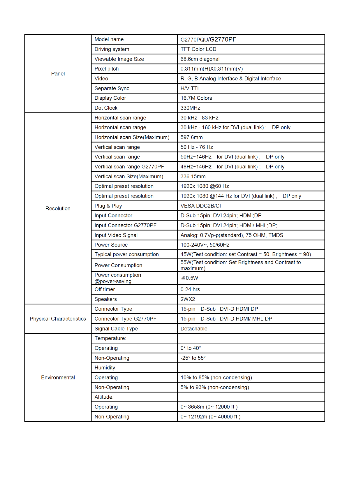
1. Monitor Specifications
4
Page 5
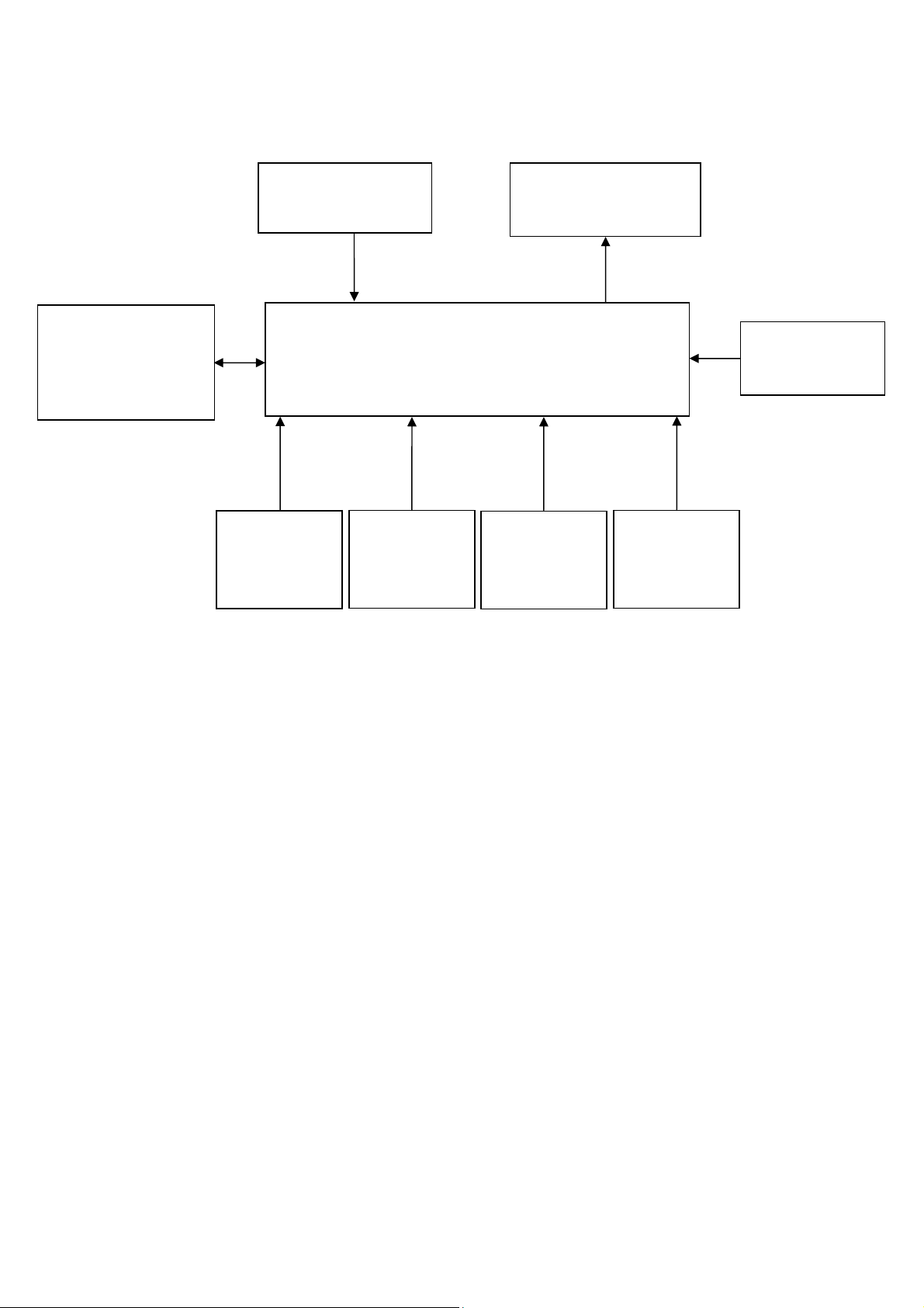
2. LLCD Monitor Description
The LCD monitor will contain a main board, a power board, an usb board and a key board which house the flat panel
control logic, brightness control logic and DDC.
The power part will provide AC to DC Inverter voltage to drive the backlight of panel and the main board chips each
voltage.
Power Board
AC-IN
100V-240V
Monitor Block Diagram
LED Drive.
Flat Panel and
LED backlight
Main Board
Key Board USB Board
HOST Computer
RS232 Connector
For white balance
adjustment in factory
Video signal, DDC
5
Page 6
3. Operating Instructions
3.1 General Instructions
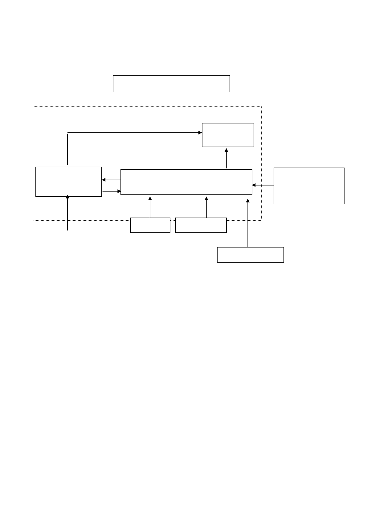
Press the power button to turn the monitor on or off. The other control knobs are located at front panel of the monitor
(See Figure ). By changing these settings, the picture can be adjusted to your personal preferences.
* The power cord should be connected.
* Press the power button to turn on the monitor. The power indicator will light up.
3.2 Control Buttons and Connections
1 Source/Auto/Exit
2 Game Mode/-
3 Volume/+
4 Menu/Enter
5 Power
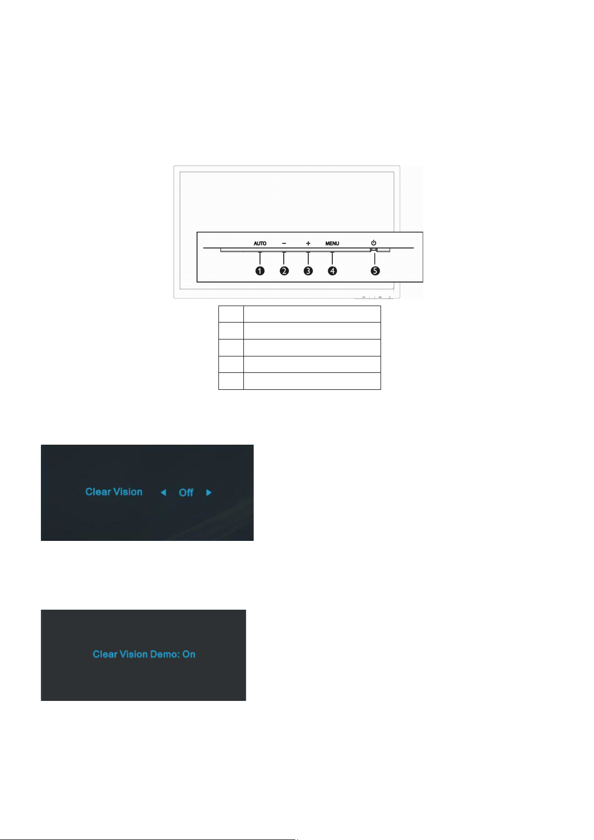
Clear Vision
1. When there is no OSD, Press the “-” button to activate Clear Vision.
2. Use the “-” or “+” buttons to select between weak, medium, strong, or off settings. Default setting is always “off”.
3. Press and hold “-” button for 5 seconds to activate the Clear Vision Demo, and a message of “Clear Vision Demo:
on” will be display on the screen for a duration of 5 seconds. Press Menu or Exit button, the message will disappear.
Press and hold “-” button for 5 seconds again, Clear Vision Demo will be off.
Clear Vision function provides the best image viewing experience by converting low resolution and blurry images into
clear and vivid images.
6
Page 7
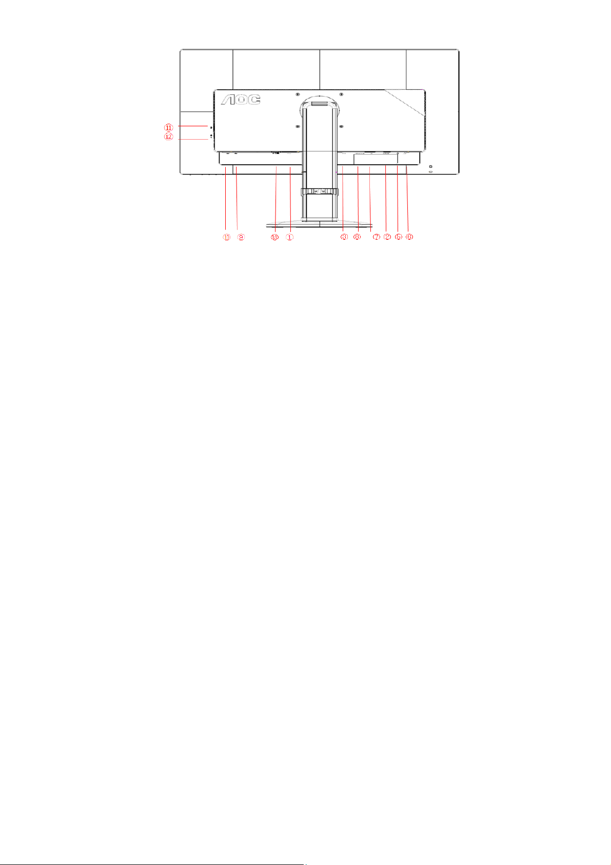
1. Power
2. Analog (D-Sub 15-Pin VGA cable)
3. DVI
4. HDMI
5. Audio in
6. Earphone out
7. Display port
8. HDMI/MHL
9. USB input
10. USB 2.0x2
11. USB 3.0
12. USB 3.0+ fast charging
13. AC power switch
To protect equipment, always turn off the PC and LCD monitor before connecting.
1. Connect the power cable to the AC port on the back of the monitor.
2. Connect one end of the 15-pin D-Sub cable to the back of the monitor and connect the other end to the computer's D-Sub port.
3. (Optional –Requires a video card with DVI port)Connect one end of the DVI cable to the back of the monitor and connect the
other end to the computer’s DVI port.
4. (Optional – Requires a video card with HDMI port) - Connect one end of the HDMI cable to the back of the monitor and connect
the other end to the computer’s HDMI port.
5. (Optional – Requires a video card with DP port) - Connect one end of the DP cable to the back of the monitor and connect the
other end to the computer’s DP port.
6. (Optional – Requires a video card with MHL port) - Connect one end of the MHL cable to the back of the monitor and connect the
other end to the computer’s MHL port.
7. (Optional)Connect the audio cable to audio in port on the back of the monitor
8. Turn on your monitor and computer.
If your monitor displays an image, installation is complete. If it does not display an image, please refer Troubleshooting.
7
Page 8

3.3 OSD Setting
Basic and simple instruction on the control keys.
1. Press the MENU-button to activate the OSD window.
2. Press - or + to navigate through the functions. Once the desired function is highlighted, press the MENU-button to
activate. Press - or + to navigate through the sub-menu. Once the desired function is highlighted, press MENU-button
to activate.
3. Press - or + to change the settings of the selected function. Press AUTO to exit. If you want to adjust any other
function, repeat steps 2-3.
4. OSD Lock Function: To lock the OSD, press and hold the MENU-button while the monitor is off and then press
power-button to turn the monitor on. To un-lock the OSD, press and hold the MENU-button while the monitor is off
and then press power-button to turn the monitor on.
Notes:
1. If the product has only one signal input, the item of "Input Select" is disabled.
2. If the product screen size is 4:3 or input signal resolution is wide format, the item of "Image Ratio" is disabled.
3. One of Clear vision, DCR, Color Boost, and Picture Boost functions is activated; the other three functions are turned
off accordingly.
8
Page 9
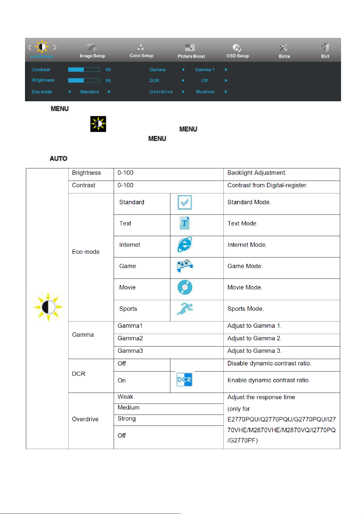
Luminance
1 Press
2 Press - or + to select
3 Press - or + to select submenu, and press
4 Press - or + to adjust.
5 Press
(Menu) to display menu.
(Luminance), and press to enter.
to exit.
to enter.
9
Page 10

10 11
Page 11

Image Setup
1 Press
(Menu) to display menu.
2 Press - or + to select
3 Press - or + to select submenu, and press
4 Press - or + to adjust.
5 Press
to exit.
(Image Setup), and press to enter.
to enter.
Page 12
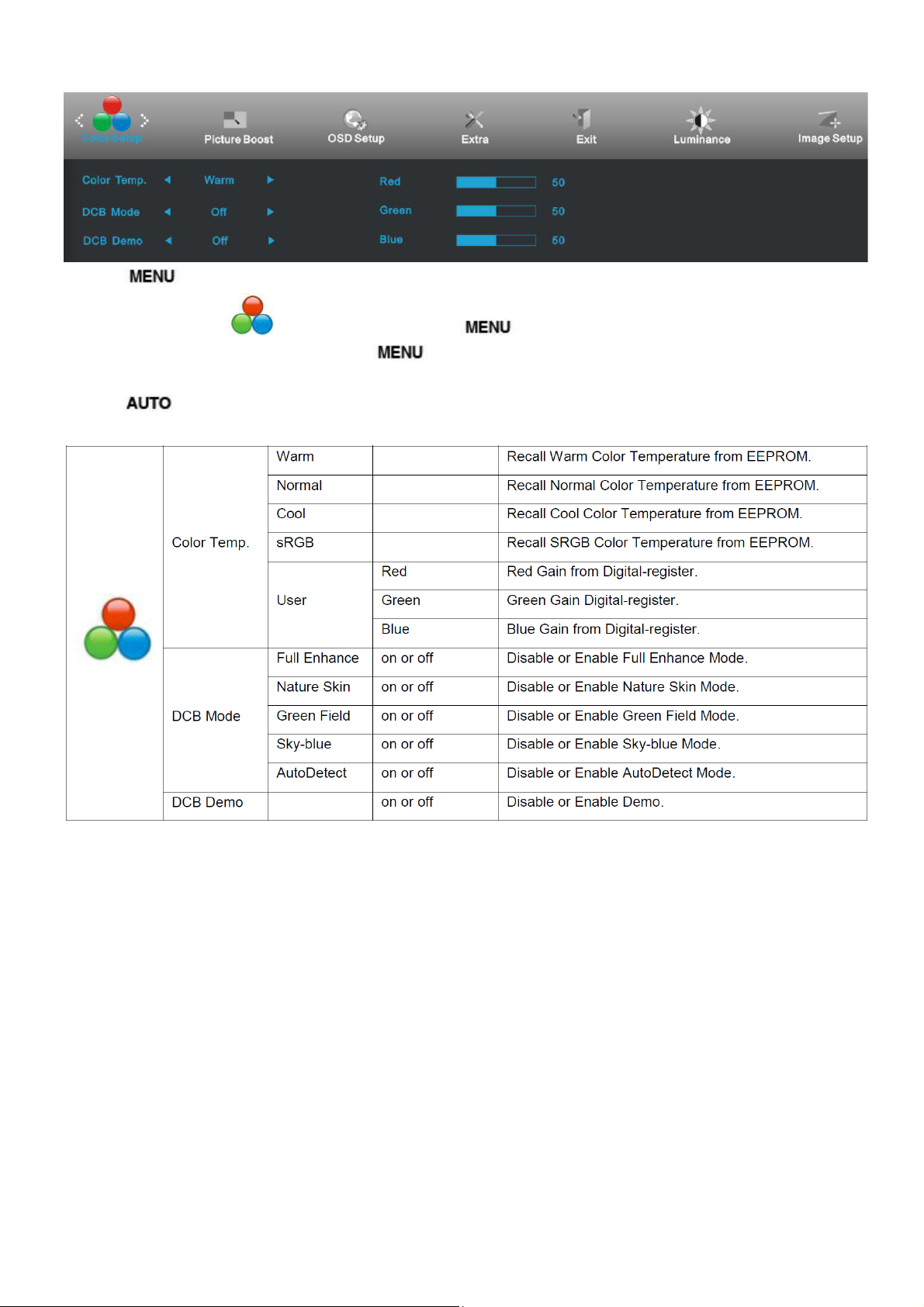
Color Setup
1 Press
(Menu) to display menu.
2 Press - or + to select
3 Press - or + to select submenu, and press
4 Press - or + to adjust.
5 Press
to exit.
(Color Setup), and press to enter.
to enter.
12
Page 13
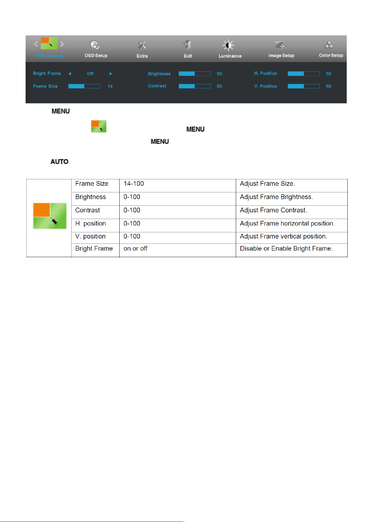
Picture Boost
1 Press
2 Press - or + to select
3 Press - or + to select submenu, and press
4 Press - or + to adjust.
5 Press
(Menu) to display menu.
(Picture Boost), and press to enter.
to exit.
to enter.
13
Page 14
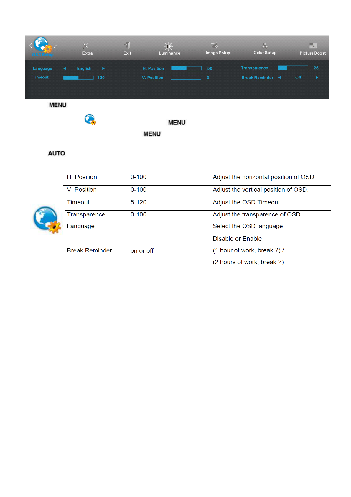
OSD Setup
1 Press (Menu) to display menu.
2 Press - or + to select
3 Press - or + to select submenu, and press
4 Press - or + to adjust.
5 Press
to exit.
(OSD Setup), and press to enter.
to enter.
14
Page 15
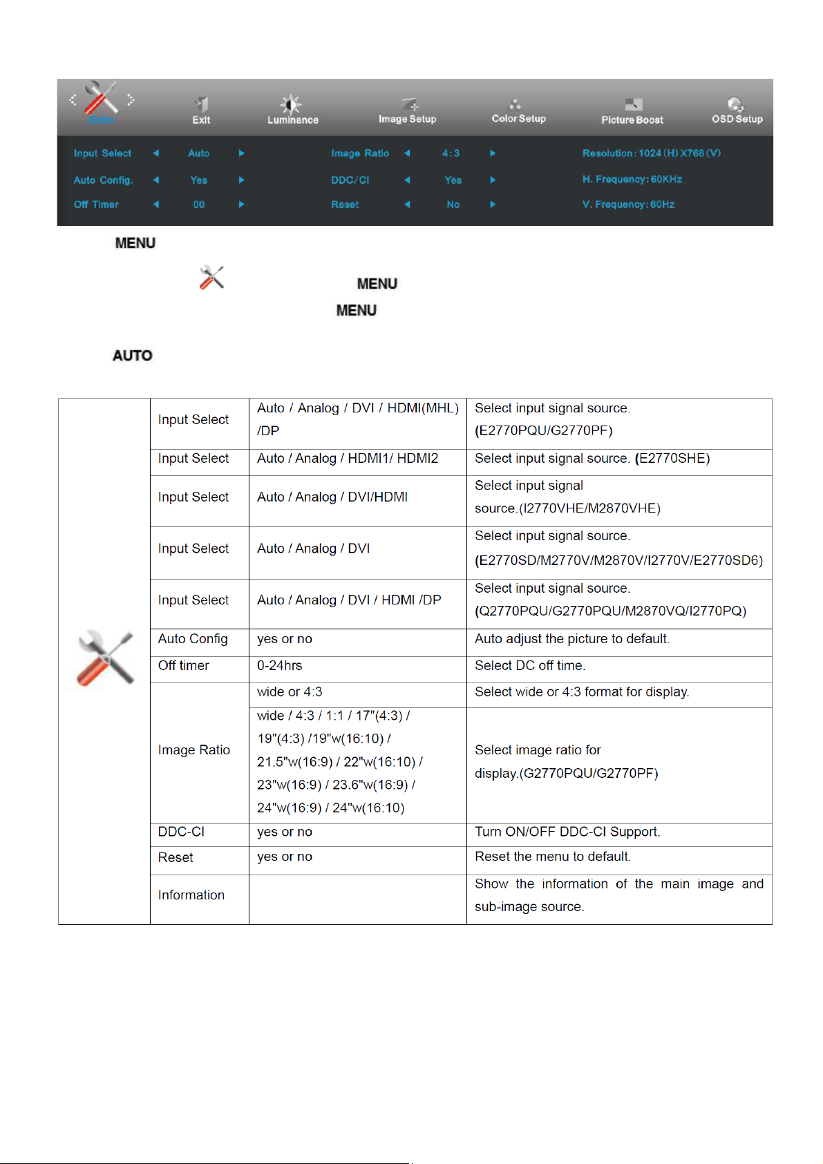
Extra
1 Press
2 Press - or + to select
3 Press - or + to select submenu, and press
4 Press - or + to adjust.
5 Press
(Menu) to display menu.
(Extra), and press to enter.
to exit.
to enter.
15
Page 16

Exit
1 Press
2 Press - or + to select
3 Press
(Menu) to display menu.
to exit.
(Exit), and press to enter.
16
Page 17
LED Indicators
Status LED Color
Full Power Mode Green or Blue
Active-off Mode Orange or red
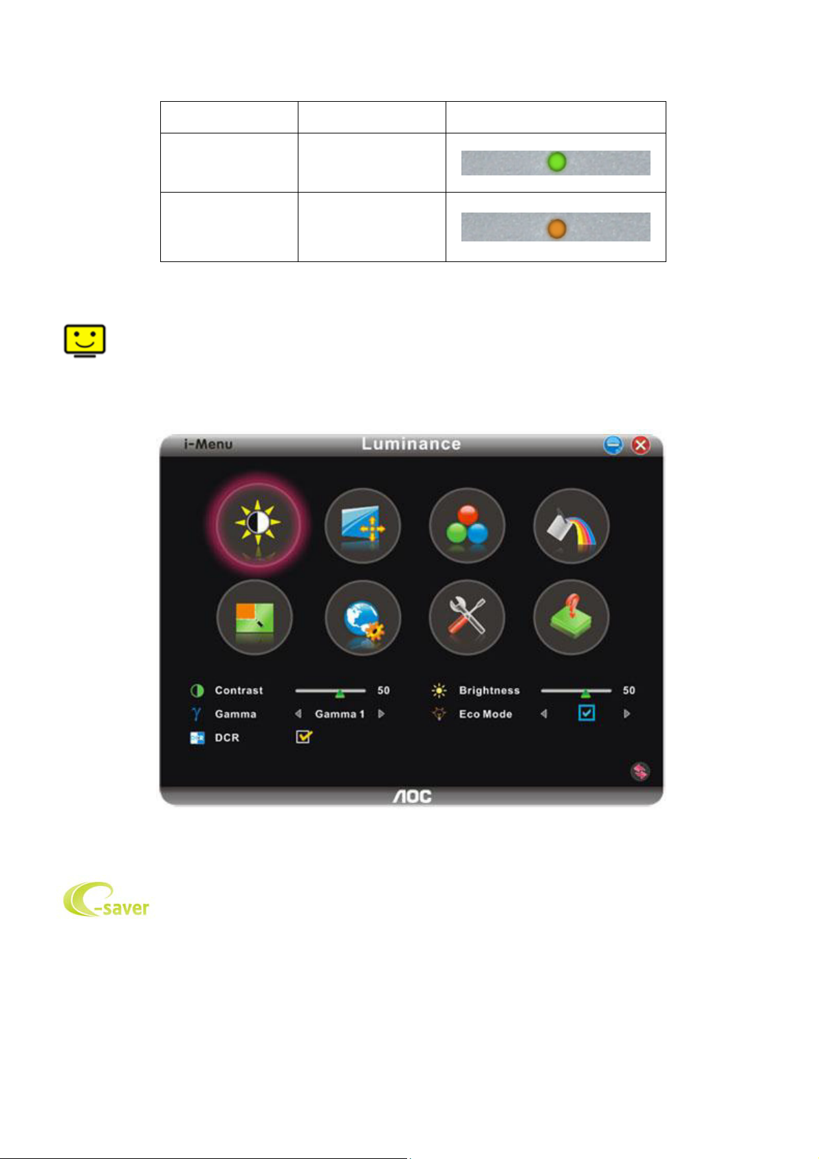
i-Menu
Welcome to “i-Menu” software by AOC. i-Menu makes it easy to adjust your monitor display setting by using on
screen menus instead of the OSD button on the monitor. To complete installation, please follow the installation guide.
e-Saver
Welcome to use AOC e-Saver monitor power management software! The AOC e-Saver features Smart Shutdown
functions for your monitors, allows your monitor to timely shutdown when PC unit is at any status (On, Off, Sleep or
Screen Saver); the actual shutdown time depends on your preferences (see example below).
Please click on "driver/e-Saver/setup.exe" to start installing the e-Saver software, follow the install wizard to
complete software installation.
Under each of the four PC status, you may choose from the pull-down menu the desired time (in minutes) for your
17
Page 18
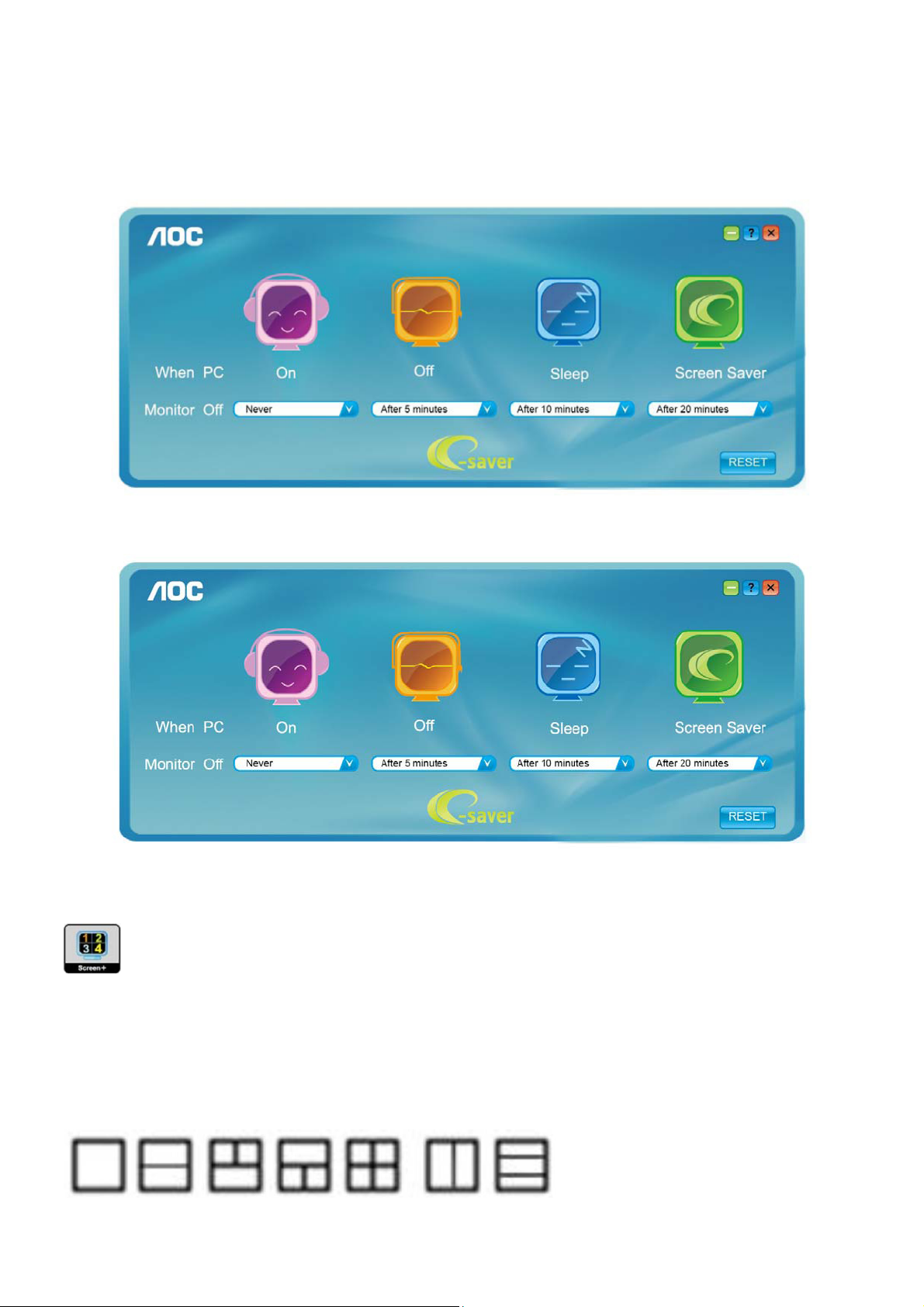
monitor to automatically shutdown. The example above illustrated:
1) The monitor will never shutdown when the PC is powered on.
2) The monitor will automatically shutdown 5 minutes after the PC is powered off.
3) The monitor will automatically shutdown 10 minutes after the PC is in sleep/stand-by mode.
4) The monitor will automatically shutdown 20 minutes after the screen saver appears.
You can click “RESET” to set the e-Saver to its default settings like below.
Screen+
Welcome to "Screen+" software by AOC, Screen+ software is a desktop screen splitting tool, it splits the desktop into
different panes, each pane displays a different window. You only need to drag the window to a corresponding pane,
when you want to access it. It supports multiple monitor display to make your task easier. Please follow the installation
software to install it.
18
Page 19
4. Input/Output Specification
4.1 Input Signal Connector
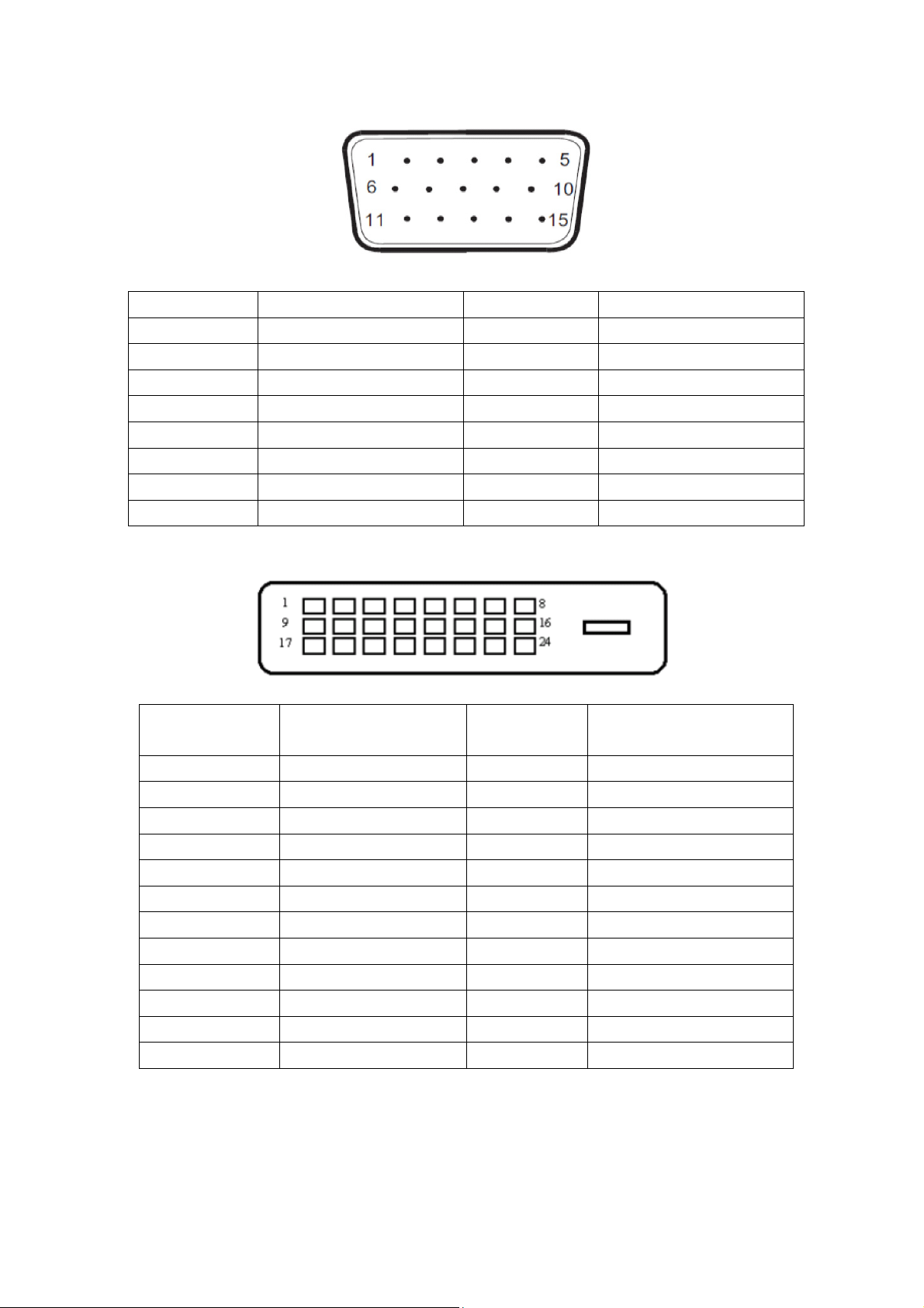
15-Pin Color Display Signal Cable
Pin No. Signal Name Pin No. Signal Name
1 Video-Red 9 +5V
2 Video-Green 10 Ground
3 Video-Blue 11 N.C.
4 N.C. 12 DDC-Serial data
5 Detect Cable 13 H-sync
6 GND-R 14 V-sync
7 GND-G 15 DDC-Serial clock
8 GND-B
24-Pin Color Display Signal Cable
Pin Number 24-Pin Color Display
Signal Cable
1
2
3 TMDS data 2/4 Shield 15 Ground (for+5V)
4
5
6 DDC Clock 18
7 DDC Data 19 TMDS data 0/5 Shield
8 N.C. 20
9
10
11 TMDS data 1/3 Shield 23 TMDS Clock +
12
TMDS data 2-
TMDS data 2+
TMDS data 4-
TMDS data 4+
TMDS data 1-
TMDS data 1+
TMDS data 3-
Pin Number 24-Pin Color Display
Signal Cable
13
14
16 Hot Plug Detect
17
21
22 TMDS Clock Shield
24
TMDS data 3+
+5V Power
TMDS data 0-
TMDS data 0+
TMDS data 5-
TMDS data 5+
TMDS Clock -
19
Page 20
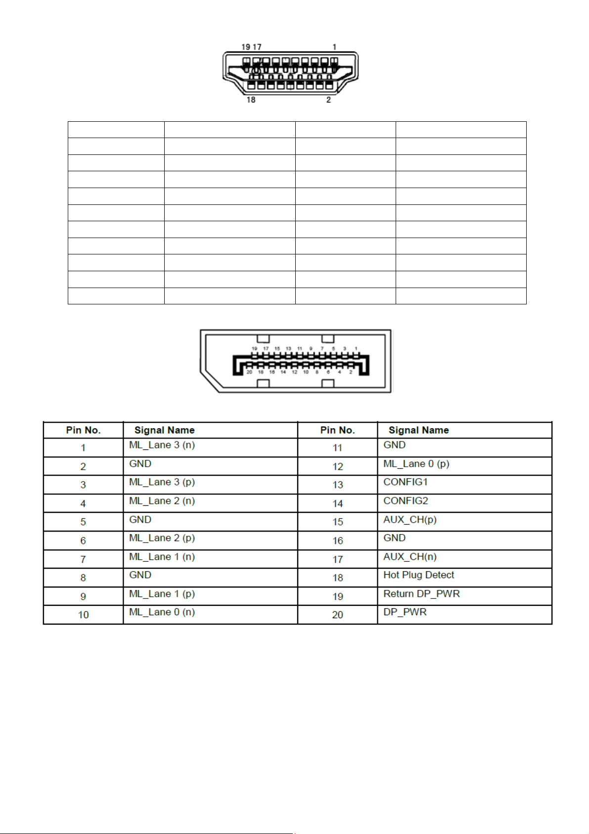
19-Pin Color Display Signal Cable
Pin No. Signal Name Pin No. Signal Name
1 TMDS Data 2+ 11 TMDS Clock Shield
2 TMDS data 2 Shield 12 TMDS Clock
3 TMDS Data 2 13 CEC
4 TMDS Data 1+ 14 Reserved (N.C. on device
5 TMDS Data 1 Shield 15 SCL
6 TMDS Data 1 16 SDA
7 TMDS Data 0+ 17 DDC/CEC Ground
8 TMDS Data 0 Shield 18 +5V Power
9 TMDS Data 0 19 Hot Plug Detect
10 TMDS Clock +
20-Pin Color Display Signal Cable
20
Page 21
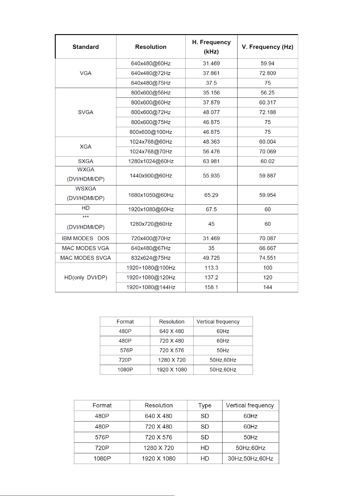
4.2 Preset Display Modes
HDMI/DP Timing
MHL Timing
21
Page 22

4.3 Panel Specification
4.3.1 General Features
4.3.2 Display Characteristics
4.3.3 Electrical Characteristics
TFT LCD MODULE
Back Light Unit
Ta = 25 ºC
22
Page 23

4.3.4 Optical Characteristics
TEST CONDITIONS
23
Page 24
5. Block Diagram
5.1 Main Board
715G7485M0D000005I
FLASH MEMORY
MX25L8006EM1I-12
G 8Mb
(U402)
Crystal 12M
D-Sub
Connector
(CN101)
(X401)
Scalar NT68372UMBG/F
(U401)
DVI
Connector
(CN501)
Connector
LCD Interface
(CN7737、CN7738)
HDMI
(CN502)
Key Control
Interface
(CN404)
DP
Connector
(CN104)
24
Page 25

5.2 Power Board
715G5665P02000003M
AC input
EMI filter
16V
ON/OFF
DIM
Bridge
Rectifier
and Filter
Start Resistor
(R904,R905,R906)
PWM Control
LD7750RGR
(IC901)
L801
PWM Control
OZ9998MGN
Transformer
Power Switch
(Q901)
MOSFET
(Q801)
(U801)
(T901)
Photo coupler
(IC903)
D803
C809
Rectifier
diodes
16V
5V
Feedback
Circuit
Regulator
(IC904)
LED
(CN804)
25
Page 26

6. Schematic
6.1 Main Board
715G7485M0D000005I
R/A: 088G 35315F HD HF
V/T: 088G 35315FVCL HF
DDC1_SCL6
DDC1_SDA6
WP_DDC3,5,6
DDC1_SCL
DDC1_SDA
ZD103
RLZ5.6B
DDC1_SCL
DDC1_SDA
GIN0
R102
47 OHM 1/16W
VSIN0
HSIN0
R104
47 OHM 1/16W
ZD102
RLZ5.6B
R101
4.7K1/16W
DDCSCL_A
DDCSDA_A
R113
RIN0
+3V3
R123
HSIN0
VSIN0
100K1/16W
VGA_CABLE_DET
BIN0
BIN0-
GIN0
GIN0-
RIN0
RIN0-
FB102
1 2
19R 0.5A
FB103
1 2C105
19R 0.5A
FB104
1 2
19R 0.5A
VGA_CABLE_DET 6
C103
5PF 50V
C108
5PF 50V
C112
5PF 50V
R118
0R05 OHM
R105
75OHM +-5% 1/8W
R110
75OHM +-5% 1/8W
R116
75OHM +-5% 1/8W
R103
10 OHM
R106
47 OHM 1/16W
R7967
470R 1/16W 1%
R109
10 OHM
R111
47 OHM 1/16W
R115
10 OHM
R117
47 OHM 1/16W
R119 100OHM
R120 100OHM
C102
47N16V
C104
47N16V
C107
47N16V
C109
47N16V
C110
47N16V
C113
47N16V
C7939
1N 50V
GND_B
GND_G
GND_R
B
G
R
DSUB_H 6
DSUB_V 6
B6
GND_B 6
SOG 6
G6
GND_G 6
R6
GND_R 6
CN101
5
15
10
4
14
9
3
13
8
2
12
7
1
11
6
17 16
DB15
+5V VGA_5V
+5V3,5,6,7,9, 10
R114
22K1/16W
4.7K1/16W
1
2
3
BIN0
D101
BAV70
U101
8
VCC
7
WC
6
SCL
5
M24C 02-R MN6 TP
VSS4SDA
E0
E1
E2
BIN0
BIN0GIN0
GIN0RIN0
RIN0-
1 2
C101
NC
1
2
3
FB101
300R 0.2A
VGA_5V
NC
C111
220N16V
R112 100OHM
ZD106
RLZ5.6B
VGA_5V
ZD101
RLZ5.6B
C114
C115
R122
NC
NC
2.2K 1/16W
OEM MODEL
TPV MO DEL
PCB NAME
02. INPUT
R121
2.2K 1/16W
ZD104
ZD105
RLZ5.6B
R125
200 OHM
3
D103
BAV99
1
2
C125
100N 16V
R126
200 OHM
3
D104
BAV99
1
2
C126
100N 16V
R127
200 OHM
3
D105
BAV99
+5V
1
2
C127
100N 16V
C128
NC/100N16V
Put Near D-SUB Connector
RLZ5.6B
T P V ( Top Victory Electronics Co . , Ltd. )
絬 隔 瓜 絪 腹
Key Component
Date
Sheet
C116
C117
22P 50V
22P 50V
AOC
of
210
Size
Rev
称爹
<
Custom
A
称爹
>
26
Page 27

HDMI/MHL
CN502
20
SHELL1
D2 Shield
22
SHELL3
D1 Shield
D0 Shield
CK Shield
CE Remote
DDC CLK
DDC DATA
23
GND
SHELL4
HP DET
21
SHELL2
HDMI
D502
BAT54C
U508
10
CH1
NC
9
CH2
NC
8
VN
VN
7
CH3
NC
6
CH45NC
AOZ8804DI
U507
10
CH1
NC
9
CH2
NC
8
VN
VN
7
CH3
NC
6
CH45NC
AOZ8804DI
+5V 2,5,6,7,9,10
HDMI1/CKHDMI1/CK+
HDMI1/D0-
DDC_5V
R549
4.7K1/16W
PW_CTRL
R547
10K
R550
CD_SENSE 6
100OHM
R543
C506
300K
47N16V
1
D2+
2
3
D2-
4
D1+
5
6
D1-
7
D0+
8
9
D0-
10
CK+
11
12
CK-
13
14
NC
15
16
17
18
1 2
+5V
19
FB502
120R 6A
C507
100N 16V
HDMI1_HOTPLUG
C509
NC
HDMI1_+5V
HDMI1_+5V
ZD504
RLZ5.6B
HDMI1_DET
HDMI1_+5V
Q504
LMBT3906LT1G
DET_HDMI1 6
R551
1K
Q502
2N7002
CEC_CTRL
R558
1M 1/16W
LMBT3904LT1G
R536
10 OHM
Q503
R554
47K
CBUS/HPD 6
HDMI1/D2+
HDMI1/D2HDMI1/D1+
HDMI1/D1HDMI1/D0+
HDMI1/D0HDMI1/CK+
HDMI1/CK-
HDMI1_SCL_A
HDMI1_SDA_A
R546 47K
R530
15K 1/16W
PW_CTRL
ZD503
NC/ RLZ5.6B
R538 47 OHM 1/16W
R539 47 OHM 1/16W
HDMI1_SDA6
HDMI1_SCL6
DDC_5V
R521 0R05 OH M
R522 0R05 OH M
R523 0R05 OH M
R524 0R05 OH M
R525 0R05 OH M
R526 0R05 OH M
R527 0R05 OH M
R529 0R05 OH M
R534
R533
4.7K1/16W
4.7K1/16W
R535
22K1/16W
WP_DDC
HDMI1_D2+ 6
HDMI1_D2- 6
HDMI1_D1+ 6
HDMI1_D1- 6
HDMI1_D0+ 6
HDMI1_D0- 6
HDMI1_CK+ 6
HDMI1_CK- 6
U505
8
E0
VCC
7
E1
WC
6
E2
SCL
5
VSS4SDA
M24C02-RMN6TP
WP_DDC 2,5,6
C508
1
2
3
220N16V
HDMI1/D0+
HDMI1/D1-
HDMI1/D2- HDMI1/D2HDMI1/D2+
HDMI1_+5V
+5V
HDMI1/CK-
1
HDMI1/CK+
2
3
HDMI1/D0-
4
HDMI1/D0+
HDMI1/D1-
1
HDMI1/D1+HDMI1/D1+
2
3
4
HDMI1/D2+
R540
33K 1/16W
R541
6.2K 1/1 6W
HDMI1_DET
Q505
LMBT3904LT1G
MHL_PS_CTRL6
R552
0R05 OHM
+5V
U509
G5250K1T1U
4
OUT
IN
EN1OC
GND
2
C511
R548
1uF 10V
4.7K1/16W
5
3
NC/100K 1/16W 5%
R555
HDMI1_+5V
HDMI_OC 6
C510
NC/22uF 10V
HDMI1_+5V
HDMI1_HOTPLUG
T P V ( Top Victory Electronics Co . , Ltd. )
絬 隔 瓜 絪 腹
Key Component
03. HDMI
Date
U506
1
I/O 1
2
VSS
I/O 23I/O 3
AT2042K6-5.0TRG1
I/O 4
N/A
6
5
4
OEM MOD EL
TPV MOD EL
PCB NAME
Sheet
HDMI1_DET
CD_SENSE
AOC
310
of
C
Size
Rev
A
<
称爹
>
称爹
27
Page 28

CN104
21
23
24
22
SHELL1
SHELL3
SHELL4
SHELL2
DP CONN
ML_ Lane 3(n)
GND
ML_ Lane 3(p)
ML_ Lane 2(n)
GND
ML_ Lane 2(p)
ML_ Lane 1(n)
GND
ML_ Lane 1(p)
ML_ Lane 0(n)
GND
ML_ Lane 0(p)
GND
GND
AUX_CH(p)
GND
AUX_CH(n)
Hot Plug Detect
Return
DP_PWR
1
2
3
4
5
6
7
8
9
10
11
12
13
14
15
16
17
18
19
20
C145
100N 16V
R/A: 088G 34320A BL
V/T: 088G 34320EVFA
DP3N
DP3P
DP2N
DP2P
DP1N
DP1P
DP0N
DP0P
DPGND
R177 0R 05 OHM
DPGND
DP_AUX_CHP
DP_AUX_CHN
DP_PLUGIN
DP_RE TURN
DP_P WR
R182 0R05 O HM
R179 0R 05 OHM
DP_VDD
C156 1U F 16V
C151 1U F 16V
C153 1U F 16V
C155 1U F 16V
C157 1U F 16V
C152 1U F 16V
C154 1U F 16V
C158 1U F 16V
DP_DET1
DP_RX3N 6
DP_RX3P 6
DP_RX2N 6
DP_RX2P 6
DP_RX1N 6
DP_RX1P 6
DP_RX0N 6
DP_RX0P 6
R180 0R05 OHM
R181 0R 05 OHM
R178 1K
+3V3
DP_VDD
R1751M 1/16W
R1861M 1/ 16W
R151
100K1/16W
DP_DET 6
C149
100N 16V
C150
100N 16V
DP_AUXP 6
DP_AUXN 6
DP3N
R190 NC/ 100K 1/16W 5%
DP3P
R191 NC/ 100K 1/16W 5%
DP2N
R192 NC/ 100K 1/16W 5%
DP2P
R193 NC/ 100K 1/16W 5%
DP1N
R194 NC/ 100K 1/16W 5%
DP1P
R195 NC/ 100K 1/16W 5%
DP0N
R196 NC/ 100K 1/16W 5%
DP0P
R197 NC/ 100K 1/16W 5%
DP_RX 1N
DP_RX 1P
DP_RX 0N
DP_RX 0P
DP_VDD
DP_RX 3N
DP_RX 3P
DP_3V3 DP_VDD
DP_3V310
C147
100N 16V
FB106
120R 6A
1 2
DP_V DD
+
C146
100UF16V
C148
100N 16V
R187
1K
R188
10 OHM
DP_HPD 6
T P V ( Top Victory Electronics Co . , Ltd. )
絬 隔 瓜 絪 腹
Key Component
04. DP
Date
DP_RX 2N
DP_RX 2P
DP_AUX_CHP
DP_AUX_CHN DP_AU X_CHN
DP_PLUGIN
DP_DET1
OEM MOD EL
TPV MO DE L
PCB NAME
Sheet
U114
1
CH1
NC
2
CH2
NC
3
VN
VN
4
CH3
NC
CH45NC
AOZ8804DI
U115
1
CH1
NC
2
CH2
NC
3
VN
VN
4
CH3
NC
CH45NC
AOZ8804DI
U116
1
CH1
NC
2
CH2
NC
3
VN
VN
4
CH3
NC
CH45NC
AOZ8804DI
AOC
410
of
DP_RX 1N
10
DP_RX 1P
9
8
DP_RX 0N
7
DP_RX 0P
6
DP_RX 3N
10
DP_RX 3P
9
8
DP_RX 2N
7
DP_RX 2P
6
10
9
8
7
6
DP_AUX_CHP
DP_PLUGIN
DP_DET1
Size
Rev
称爹
B
A
<
称爹
>
28
Page 29

JACK
CN501
VSYN C
SYNC GND
DDC SCL
DDC SDA
1/3shield
2/4shield
0/5shield
clk shield
28
DAT0+
DAT0-
DAT1+
DAT1-
DAT2+
DAT2-
DAT3+
DAT3-
DAT4+
DAT4-
DAT5+
DAT5-
GND26GND25GND27GND
HPD
+5V
clk+
clk-
+3V3
R150
ZD112
RLZ5.6B
1 2
100K1/16W
ZD110
NC/ RLZ5.6B
1 2
C131
NC/ 100N 16V
8
DET_DVI
15
SCL_DVI
6
SDA_DVI
7
14
HPD
16
11
3
19
22
DAT0+
18
DAT0-
17
DAT1+
10
DAT1-
9
DAT2+
2
DAT2-
1
DAT3+
13
DAT3-
12
DAT4+
5
DAT4-
4
DAT5+
21
DAT5-
20
DCLK+
23
DCLK-
24
R143 100OHM
R148 47 OHM 1/16W
R149 47 OHM 1/16W
300R 0.2A
NC/ 100N 16V
DVI_DET 6
FB107
C132
DVI5V
R147 4.7K1/16W
ZD111
RLZ5.6B
1 2
R137 10 OHM
R134 10 OHM
R135 10 OHM
R129 10 OHM
R141 10 OHM
R131 10 OHM
R142 10 OHM
R132 10 OHM
R140 10 OHM
R139 10 OHM
R136 10 OHM
R133 10 OHM
R138 10 OHM
R128 10 OHM
Q101NC
DVI_HPD 6
DVI_RX0+ 6
DVI_RX0- 6
DVI_RX1+ 6
DVI_RX1- 6
DVI_RX2+ 6
DVI_RX2- 6
DVI_RX3+ 6
DVI_RX3- 6
DVI_RX4+ 6
DVI_RX4- 6
DVI_RX5+ 6
DVI_RX5- 6
DVI_RXC+ 6
DVI_RXC- 6
R145 4. 7K1/16W
+5V2, 3,6,7,9, 10
R144
22K1/16W
R146 4. 7K1/16W
2
3
WP_DDC
DVI5V+5V
1
D106
BAV70
U102
8
VCC
7
WC
6
SCL
5
M24C02-RMN6TP
WP_DDC 2,3,6
DVI_SCL 6
DVI_SDA 6
C130
1
E0
2
E1
3
E2
VSS4SDA
220N16V
DVI
R/A: 088G 35424FXNH HF
V/T: 088G354GOF1VXH HF
R/A: 088G 35424F C HF(no shield)
V/T: 088G 35424F VC HF( no shield)
DCLKDCLK+
DAT0DAT0+
10
9
8
7
6
U104
CH1
NC
CH2
NC
VN
VN
CH3
NC
CH45NC
AOZ8804DI
10
9
8
7
6
U106
CH1
NC
CH2
NC
VN
VN
CH3
NC
CH45NC
AOZ8804DI
DAT3DAT3+
DAT4DAT4+
DCLK-
1
DCLK+
2
3
DAT0-
4
DAT0+
DAT1DAT1+
DAT2DAT2+
10
9
8
7
6
U105
CH1
NC
CH2
NC
VN
VN
CH3
NC
CH45NC
AOZ8804DI
DAT1-
1
DAT1+
2
3
DAT2-
4
DAT2+
DAT3-
1
DAT3+
2
3
DAT4-
4
DAT4+
T P V ( Top Victory Electronics Co . , Ltd. )
絬 隔 瓜 絪 腹
Key Component
Date
DAT5DAT5+
SCL_DVI
SDA_DVI
05. DVI INPUT
10
9
8
7
6
U103
CH1
NC
CH2
NC
VN
VN
CH3
NC
CH45NC
AOZ8804DI
1
2
3
4
DAT5DAT5+
SCL_DVI
SDA_DVI
OEM MODEL
TPV MODEL
PCB NAME
Sheet
AOC
of
510
Size
Rev
称爹
称爹
<
Custom
A
>
29
Page 30

HDMI/MHL IN
DP IN
VGA IN
Dual DVI IN
FFC
LBADC_2
LBADC2
POWER_KEY #
LED_R
FFC
LED_R
8
6
4
2
CN401
NC/CONN
6
4
2
7
5
3
1
CN405
NC/CONN
+5V
+3V3
R7854
R7855
NC/4.7K1/16W
BL_ADJ10
U401D
HDMI1_CK-3
HDMI1_CK+3
HDMI1_D0-3
HDMI1_D0+3
HDMI1_D1-3
HDMI1_D1+3
HDMI1_D2-3
HDMI1_D2+3
DP_RX0N4
DP_RX0P4
DP_RX1N4
DP_RX1P4
DP_RX2N4
DP_RX2P4
DP_RX3N4
DP_RX3P4
DP_AUXP4
DP_AUXN4
B2
GND_B2
SOG2
G2
GND_G2
R2
GND_R2
DSUB_H2
DSUB_V2
DVI_RXC-5
DVI_RXC+5
DVI_RX0-5
DVI_RX0+5
DVI_RX1-5
DVI_RX1+5
DVI_RX2-5
DVI_RX2+5
DVI_RX3-5
DVI_RX3+5
DVI_RX4-5
DVI_RX4+5
DVI_RX5-5
DVI_RX5+5
LBADC_1
LBADC1
LED_G
GND
LBADC1LBADC2
5
LED_GPOWER_KEY #
3
1
GND
C1
C2
C3
D3
E2
E1
E3
F1
H2
G3
J1
H3
K2
J3
L1
L2
B2
B3
F3
F2
M3
M2
N3
N1
N2
P2
P1
R1
R2
A11
B11
C11
C10
B9
A9
C9
A8
B8
C8
B7
B6
A6
C6
A5
B5
NT68372UMBG/F
RX1CB
RX1C
RX10B
RX10
RX11B
RX11
RX12B
RX12
RX2CB
RX2C
RX20B
RX20
RX21B
RX21
RX22B
RX22
RXAUX1
RXAUX1N
RXAUX2
RXAUX2N
BIN1+
BIN1SOGIN
GIN1+
GIN1RIN+
RINHSYNCI0
VSYNC I0
RX3CB
RX3C
RX30B
RX30
RX31B
RX31
RX32B
RX32
RX4CB
RX4C
RX40B
RX40
RX41B
RX41
RX42B
RX42
R7860
1K
EN_AUDI O5V8
AUDIO_SD8
DVI_HPD5
+3V3
R7861
1K
DVI_SDA5
DVI_SCL5
DVI_DET5
USB_ON10
CBUS/HPD3
MHL_PS_CTRL3
HDMI1_SCL3
HDMI1_SDA3
CD_SENSE3
DET_HDMI13
DP_HPD4
DP_DET4
HDMI_OC3
DDC1_SCL2
DDC1_SDA2
AUDIO_MUTE8
VOLUME8
VGA_CABLE_DET2
BL_EN10
PANEL_ENABLE7
PANEL_SCL7
PANEL_SDA7
PANEL_CTRL17
PANEL_CTRL27
PS_ON10
WP_DDC2,3,5
POWER_KEY #
LED_GRN/BLUE
LED_ORANGE
KEY2
KEY1
SCL
SDA
PANEL_SCL
PANEL_SDA
NT68372UMBG/F
U401E
A4
PC3#/CEC #
C5
PC0#/CEC #
E8
PF7*/VBU S4*/WD _I*
E7
PA7*/DD C_SDA3*/ TXD3*
D7
PA6*/DD C_SCL3*/ RXD3*
B4
PF3*/C D_SENSE4*
C4
PD5/IR_PORT1
D4
PE4*/CBU S1*/HPD 1
D5
PF4*/VBU S1*
E4
PB4*/DD C_SCL0*/ RXD0*
E5
PB5*/DD C_SDA0*/ TXD0*
F4
PF0*/C D_SENSE1*
G4
PD4/IR_PORT3
H4
PE5*/CBU S2*/HPD 2
J4
PF5*/VBU S2*
J5
PB6*/DD C_SCL1*/ RXD1*
K4
PB7*/DD C_SDA1*/ TXD1*
K5
PF1*/C D_SENSE2*
L4
PC7/IR_PORT2
M4
PC4*/D DC_SCL4* /RXD4*
N4
PC5*/D DC_SDA4* /TXD4*
L5
PA0*/ADC 4/PWMA*
R3
PA1*/ADC 5/PWMB*
P3
PD7
R7869 100OHM
R411 1K
R404 10K
R403 10K
R412 1K
R413 1K
D8
CBUS4*/SCK_I*
PE2#/DBC#/ PWMC#/ M2_SPI_CE3
PE3#/PWMD #/M2_SPI_C E4
PA2*/ADC6/ PWMC*/DIN_19
V15
T16
U14
U15
10K
R7856
NC/4.7K1/16W
U401B
5V_DET_IN T
E10
D10
D9
PA3*/ADC7/ PWMD*/DIN_18
R16
B12
C12
A13
C13
A12
D12
E9
PD6/DI N_VS
PF2*/CD_SENSE3*/DIN _HS_CS
PA5*/DDC_SDA2*/TXD2*/DIN_HREF_DE
PB2/ADC2/I NTE2/DIN_21
PB3/ADC3/I NTE3/DIN_20
P34*/RXD 5*/DI N_16
V16
V17
R17
B13
D11
CBUS3*
PE1*/ADDR1/DIN_1
PF6*/VBU S3*/SD_I *
PC2#/DBC #/PWMB#
PE0*/LPD_I N0*/AD DR0
PB0/ADC0/ INTE0/ DIN_4
PB1/ADC1/ INTE1/ DIN_3
PA4*/DD C_SCL2*/ RXD2*/ DIN_0
P35*/TXD 6*/DI N_15
PC6/AMU TE/M2_SPI _CE2/AO_I N/DIN _17
U16
PC1#/LPD_OUT#/PWMA#
P30*/RXD */AO_OUT /DIN _14
P31*/TXD */AO_OUT B/DIN _13
PD2/M2_SPI _SO/SD_I/ DIN_12
PD3/M2_SPI _CE1/WD _I/DI N_11
PD0/M2_SPI _CLK/SCK_I /DIN _10
PD1/M2_SPI _SI/DI N_9
SPI_CE
SPI_SO
SPI_CLK
SPI_SI
T17
V14
P17
Y14
Y15
Y16
U17
W14
W15
W16
U1
OSCI
U2
OSCO
T3
RSTN
R7873 22 OHM 1/16W
R7874 22 OHM 1/16W
R7876 22 OHM 1/16W
R7879 22 OHM 1/16W
RSTN
C7844
4.7UF 10% 10V
12MHz
X401
1 2
R7868
270R 1/16W 5%
SPI_SI
SPI_CLK
SPI_SO
SPI_CE
SPI_WP
EE_WP
R7866
1M 1/16W
+3V3
PD_CTRL 9
PC_IN_D ET 8
C7840
22P 50V
C7841
22P 50V
PHY_TM
NT68372UMBG/F
T5
HEA T S INK
HS401
1
2
HEAT SINK
TP7701
CN404
CONN
C430
1 2
C431
NC
1 2
LED_R
FB411
NC/120 OH M
R468
3.9K1/16W
ZD403 NC/ MLVS0603M04
+3V3
R469
3.9K1/16W
ZD401 NC/ MLVS0603M04
ZD402 NC/ MLVS0603M04
C433
C432
NC
NC
1 2
1 2
R414
22K1/16W
LED_ORANGE
LED_GRN/BLUE
R419
22K1/16W
R415
NC
R420
NC
Q402
LMBT3906LT1G
R416
1K2 1/10W 5%
Q401
LMBT3906LT1G
330OHM 1/10W
R418
NC/0R05 OHM
R417
0R05 OHM
R422
NC
R423
0R05 OHM
R421
+3V3
LED_R
+5V
+3V3
+5V
+5V 2,3,5,7,9,10
LED_G
SPI_WP
SCL
SDA
EE_WP
R424
100OHM
SPI_CE
R425
10K
R427 47 OHM 1/16W
R428 47 OHM 1/16W
R429 100OHM
U402
1
CS#
VCC
2
SO/SIO1
HOLD#
3
WP#
SCLK
GND4SI/SIO0
MX25L8006EM1I-12G
+3V3
R449
R450
R448
4.7K1/16W
4.7K1/16W
4.7K1/16W
T P V ( Top Victory Electronics Co . , Ltd. )
絬 隔 瓜 絪 腹
Key Component
05. INPUT INTERFACE & GPIO
Date
8
7
6
R426
5
0R05 OHM
C436
NC/22pF 50V
U403
8
VCC
7
WC
6
SCL
5
M24C16
+3V3
HOLDSPI_SO
SPI_CLK
SPI_SI
C435
220N16V
C437
220N16V
1
NC
2
NC
3
NC
VSS4SDA
OEM MODEL
TPV MOD EL
PCB NAME
Sheet
AOC
of
610
A2
Size
Rev
A
称爹
>
<
称爹
LBADC_2
R470 NC /0R05 OHM
LBADC_1
R471 NC /0R05 OHM
LBADC2
R463 0R05 OHM
LBADC1
R464 0R05 OH M
7
6
6
5
5
4
4
3
3
2
2
1
1
CN402
NC/CONN
TOUCH_POW ER
ZD404 NC/ MLVS0603M04
1 2
+3V3
1 2
3.9K1/16W
KEY1
KEY2
POWER_KEY #
LED_G
LED_R
NC
FB410
NC/120 OHM
C428
NC
R467
C429
NC
30
Page 31

LVTX_A_CH0N
LVTX_A_CH0P
LVTX_A_CH1N
LVTX_A_CH1P
LVTX_A_CH2N
LVTX_A_CH2P
LVTX_A_CLKN
LVTX_A_CLKP
LVTX_A_CH3N
LVTX_A_CH3P
LVTX_A_CH4N
LVTX_A_CH4P
LVTX_B_CH0N
LVTX_B_CH0P
LVTX_B_CH1N
LVTX_B_CH1P
LVTX_B_CH2N
LVTX_B_CH2P
LVTX_B_CLKN
LVTX_B_CLKP
LVTX_B_CH3N
LVTX_B_CH3P
LVTX_B_CH4N
LVTX_B_CH4P
LVTX_C_CH0N
LVTX_C_CH0P
LVTX_C_CH1N
LVTX_C_CH1P
LVTX_C_CH2N
LVTX_C_CH2P
LVTX_C_CLKN
LVTX_C_CLKP
LVTX_C_CH3N
LVTX_C_CH3P
LVTX_C_CH4N
LVTX_C_CH4P
LVTX_D_CH0N
LVTX_D_CH0P
LVTX_D_CH1N
LVTX_D_CH1P
LVTX_D_CH2N
LVTX_D_CH2P
LVTX_D_CLKN
LVTX_D_CLKP
LVTX_D_CH3N
LVTX_D_CH3P
LVTX_D_CH4N
LVTX_D_CH4P
C20
C19
C18
D19
D18
E19
E20
E18
F20
F19
F18
G19
G18
H19
H20
H18
J20
J19
J18
K19
K18
L19
L20
L18
M20
M19
M18
N19
N18
P19
P20
P18
R20
R19
R18
T19
T18
U19
U20
U18
V20
V19
V18
W19
W18
Y18
W17
Y17
U401C
TXA0N
TXA0P
TXA1N
TXA1P
TXA2N
TXA2P
TXACKN
TXACKP
TXA3N
TXA3P
TXA4N
TXA4P
TXB0N
TXB0P
TXB1N
TXB1P
TXB2N
TXB2P
TXBCKN
TXBCKP
TXB3N
TXB3P
TXB4N
TXB4P
TXC0N
TXC0P
TXC1N
TXC1P
TXC2N
TXC2P
TXCCKN
TXCCKP
TXC3N
TXC3P
TXC4N
TXC4P
TXD0N
TXD0P
TXD1N
TXD1P
TXD2N
TXD2P
TXDCKN
TXDCKP
TXD3N
TXD3P
TXD4N
TXD4P
NT68372UMBG/F
CN7737
PSET1
PANEL_SDA6
PANEL_SCL6
R7954100OHM
R7956100OHM
LVTX_A_CH0N
LVTX_A_CH1N
LVTX_A_CH2N
LVTX_A_CLKN
LVTX_A_CH3N
LVTX_A_CH4N
LVTX_B_CH0N
LVTX_B_CH1N
LVTX_B_CH2N
LVTX_B_CLKN
LVTX_B_CH3N
LVTX_B_CH4N
PSET3
10
12
14
16
18
20
22
24
26
28
30
32
34
36
38
40
2
4
6
8
CONN
PSET0
1
PSET2
3
LVTX_A_CH0P
5
LVTX_A_CH1P
7
LVTX_A_CH2P
9
11
LVTX_A_CLKP
13
LVTX_A_CH3P
15
LVTX_A_CH4P
17
19
LVTX_B_CH0P
21
LVTX_B_CH1P
23
LVTX_B_CH2P
25
27
LVTX_B_CLKP
29
LVTX_B_CH3P
31
LVTX_B_CH4P
33
35
37
R7958 0R05 1/10W
39
R7955 100R 1/16W 5%
R7957 100R 1/16W 5%
PANEL_PWR
LVDS Connector for Third Channel & Fourth Channel
CN7738
2
LVTX_C_CH0N
LVTX_C_CH1N
LVTX_C_CH2N
LVTX_C_CLKN
LVTX_C_CH3N
LVTX_C_CH4N
LVTX_D_CH0N
LVTX_D_CH1N
LVTX_D_CH2N
LVTX_D_CLKN
LVTX_D_CH3N
LVTX_D_CH4N
1
CONN
3
5
7
9
11
13
15
17
19
21
23
25
27
29
31
33
LVTX_C_CH0P
LVTX_C_CH1P
LVTX_C_CH2P
LVTX_C_CLKP
LVTX_C_CH3P
LVTX_C_CH4P
LVTX_D_CH0P
LVTX_D_CH1P
LVTX_D_CH2P
LVTX_D_CLKP
LVTX_D_CH3P
LVTX_D_CH4P
4
6
8
10
12
14
16
18
20
22
24
26
28
30
32
34
PANEL_CTRL1
PANEL_CTRL2
PANEL_CTRL1 6
PANEL_CTRL2 6
CN711
CONN
1112
1
2
3
4
5
6
7
8
9
10
PANEL_PWR
R754 0R05 OHM
R755 0R05 OHM
C4282
100NF 25V
NC/1.2K 1/4W
GND
R4282
R4283
300 OHM 1/4W
+
C4283
220UF 35V
PANEL_PWR
1 2
Panel_VCC
FB4262
120R 6A
+19V
+19V 8,10
C7928
220uF 25V
PANEL_ENABLE6
+
C7929
10UF 25V
C7930
10UF 25V
R7965
10K
D1908
SX36F
R7959
11K 1/10W 1%
R7963
62K
C7937
820pF 50V
L7750
22UH
C7936
22pF 50V
APW7089KAI-TRG
U7750
1
8
VIN
GND
2
7
EN
FB
3
6
UGND
COMP
5
VCC4LX
C7935
1uF 25V
LX
9
D1907
SX36F
R7962
100K1/16W
C7931
1uF 25V
R7964
30Kohm 1/16W +/-5%
+5V
C7927
1uF 25V
VCC=0.8 ( 1+R7960/R7959)
R7966
100OHM
C7938
100NF 25V
Q7508
LMBT3904LT1G
Panel_VCC = 5V
R7960 = 63.4K
R7959 = 12K
R7960
59K 1/16W
C7933
10UF 25V
Panel_VCC = 12V:
R7960 = 140K
R7959 = 10K
C7926
22pF 50V
R7961
0R05 OHM
C7934
10UF 25V
Panel_VCC
+
C7932
220UF 35V
Panel_VCC = 10V:
R7960 = 115K
R7959 = 10K
T P V ( Top Victory Electronics Co . , Ltd. )
絬 隔 瓜 絪 腹
Key Component
08. DISPLAY OUTPUT INTERFACE
Date
OEM MOD EL
TPV MODEL
PCB NAME
Sheet
of
710
A2
Size
Rev
A
称爹
>
<
称爹
31
Page 32

AINR
AINL
AOUT_R
AOUT_L
JACK
Line In
CN602
PHONEJACK
HeadPhone
Out
+19V7,10
AUDIO_VDD
U401F
C16
I2S3/AIN2R
B16
I2S2/AIN2L
B17
I2S1/AIN1R
A17
I2S0/AIN1L
C17
WD
A18
SCK/AOUT_R
B18
MCLK/ AOU T_L
B19
SPDIF
NT68372UMBG/F
+3.3V_AUDIO
R6410
100K1/16W
4
5
3
2
1
R6428
0R05 OHM
+5V_AUDIO
4 R602 150R
5
3
2
1
FB601
120R 6A
1 2
R642
10K
1
AUDIO_GND
B15
L1
R1
R601
100K1/16W
+19V
C15
AUDIO_VDD
23
AUDIO_CEXT2
A15
C6839
10UF 10V
R6411 100 OHM
C6439
22pF 50V
C6443
22pF 50V
R603 100OHM
R604 150R
D601
LL4148
R644
1K
Q602
LMBT3906LT1G
R650
10K 1/10W 5%
C6838
C6837
100N 16V
10UF 10V
R6424 10K 1/10W 5%
R6431 10K 1/10W 5%
OUTL
SE
OUTR
C622
10UF 25V
AUDIO_MUTE6
+3V3
PC_IN_DET 6
R6426
12KOHM 1/ 10W
R6434
12KOHM 1/10W
R646 470OHM1/16W
R639 10K
C6440
680pF 50V
C6446
680pF 50V
C620
0.1UF 16V
+3V3 2,4,5,6,9,10
FB6749
+3.3V_AU DIO
120R 6A
C6434 2.2uF 10V
C6442 2.2uF 10V
+5V_AUDIO
R647
NC/10K
Q601
LMBT3904LT1G
+
C6833
470uF 10V
AINL
AINR
R645
22K1/16W
C6835
100N 16V
MUTE-1
C6836
100N 16V
C621
0.1UF 16V
R634
R637
10K +-1% 1/10W
MUTE-1
U601
APA2606NAI-TRG
Pad 璶 TOP and
常璶Τ
Button
C630
100pF 50V
C633
NC/10uF 25V
C631
ぃ 繦獽 ノ
DC-DC pulse
noise
FB604 120R 6A
1 2
C619
NC/22 0pF 50V
FB605
1 2
120R 6A
FB602 120R 6A
1 2
C624
NC/220pF 50V
FB603 120R 6A
1 2
AUDIO_SD 6
OEM MOD EL
TPV MODEL
PCB NAME
Sheet
+
470uF 16V
穦
C615
220pF 50V
C613
220pF 50V
C614
220pF 50V
C612
220pF 50V
AOC
810
+5V_AUDIO
C631
C634
0.1UF 16 V
,
Τ
OUT-L+
OUT-LOUT-R+
OUT-R-
of
ZD602
NC/RLZ6.2B
1 2
R649
NC/300 OHM
CN601
4
3
2
1
A2
Size
Rev
A
称爹
>
<
称爹
R635
30K OHM
C640
2.2NF 50 V
R625 33K 1/16W
Pad 璶 TOP and
常璶Τ
Button
D602
SR34
1 2
C635
22PF 50V
R618 0R05 OHMCN603
10
12
11
VOLUME
HP_LOUT
25
Thernal Pad
HP_ROUT13BYPASS14SE/BTL15AGC16RINN17GND18SD19PVDD20ROUTN21PGND22PGND23ROUTP
C610
1uF 10V
L601 22UH
R632
NC/0R05 1/10W
D603
SR34
53.6KOHM +-1% 1/10W
1 2
C639
NC/1N 50V
+5V_AUDI O
C605
10UF 10V
C607
1uF 10V
+5V_AUDIO
C604
10UF 10V
C611
1uF 10V
6
9
3
7
1
8
5
4
UVP
VDD
VDC
LINN
PVDD
PGND2PGND
MUTE
LOUTP
LOUTN
24
C609
1uF 10V
C606
10UF 10V
+5V_AU DI O
R605
100OHM
R619
10K
T P V ( Top Victory Elect ronics Co . , Ltd. )
絬 隔 瓜 絪 腹
Key Component
10. AUDIO AMP
Date
U602
R621
1K
R622
1K
12K 1% 1/16W
9
VCC4LX
3
UGND
COMP
2
EN
1
VIN
APW7089KAI-TRG
C632
1uF 25V
EN_AUDIO5V 6
R626 3K1/16W
R623
+
+
220UF 16V
C601
0.1UF 16V
C608
R620
1uF 10V
5
LX
6
7
FB
8
GND
1K
C602 0. 47uF 16V
220UF 16V
C616
C617
C603 0.47uF 16V
+19V
C629
+19V7,10
10UF 25V
+5V_AUDIO
R641
10K
VOLUME6
R638
100OHM
AOUT_L
OUTL
OUTR
1uF 25V
R633
100K1/16W
EN_AUDIO5V
R636
C638
33K 1/16W
R629 NC/750R 1/10W 5%
R628 NC/750R 1/10W 5%
100NF
+5V_AUDIO
VOL
C623
1UF 16V
SE
NC/100K 1/16W 5%
+5V_AUDIO
R627
R624 30K OHM +-1% 1/16W
C637
C636
1uF 25V
R643
10K
AOUT_R
32
Page 33

CVDD
C7892
C7893
10UF 10V
10UF 10V
VMM_AD C1 2 VDD12R X
C7904
C7910
APR1_V12
DDRPHY_12
C7905
100N 16V
C7911
100N 16V
C7915
100N 16V
10UF 10V
10UF 10V
C7914
10UF 10V
C7906
10UF 10V
C7912
10UF 10V
C7894
100N 16V
V12T
C7895
100N 16V
C7896
100N 16V
C7907
100N 16V
C7913
100N 16V
C7897
100N 16V
C7872
10UF 10V
VDD12RX
VMM_ADC12
DDRPHY_12
APR1_V12
CVDD
V12T
C7873
100N 16V
NT68372UMBG/F
C7874
10UF 10V
G7
H7
T4
U4
N7
P7
L6
M6
H8
J8
K8
L8
M8
N8
P8
R8
H9
L9
N9
R9
J7
K7
C7875
100N 16V
U401A
VDD12RX
VDD12RX
VMM_ADC12
VMM_ADC12
VCCA/VCCD
VCC_CLK
APR1_V12
APR1_V12
CVDD
CVDD
CVDD
CVDD
CVDD
CVDD
CVDD
CVDD
CVDD
CVDD
CVDD
CVDD
V12T
V12T
TGNDA1TGNDH1TGNDA2TGNDD2TGNDG2TGNDJ2TGNDK3TGNDL3GNDW1GNDW2GNDY2GNDY7GNDJ9GNDK9GNDM9GND
C7876
10UF 10V
E6
TVCC33F5TVCC33
TGNDC7TGND
B10
VDDRX33
F6
VDD33RXG5VDD33RX
C7877
100N 16V
P9
GND
GND
N13
C7879
100N 16V
DPOSC33
D16
GND
GND
P13
Y13
H14
OSC_MVCC3IO
GND
J14
10UF 10V
GND
GND
K14
DPOSC33 DVDD33MPLL_OSC33TVCC 33 VDDRX33 ADC33
C7883
100N 16V
VDD_CORE/VDD_MMU
VDD_CORE/VDD_MMU
VDD_CORE/VDD_MMU
VDD_CORE/VDD_MMU
VDD_CORE/VDD_MMU
VDD_CORE/VDD_MMU
GND
GND
GND
GND
GND
L15
K15
N15
M15
C7886
VDD_CLK
DDR_1V8
DDR_1V8
DDR_1V8
DDR_1V8
DDR_1V8
DDR_1V8
MVREF
T1
C7887
100N 16V
VDD_CLK
U9
DDR_1V8
V9
V10
W9
W10
Y9
Y10
VDD _MMU
T9
R10
T10
T11
R12
T12
R7946
10K 1/10W 1%
R7947
10K 1/10W 1%
VDD_MMU
T8
C7918
100N 16V
ADC_GND
C7898
10UF 10V
C7908
10UF 10V
C7899
10UF 10V
VDD_CLK
VDD_MMU
C7909
100N 16V
C7900
100N 16V
C7901
100N 16V
C7902
100N 16V
C7903
100N 16V
10UF 10V
OSC_GND
GND
T2
P15
C7882
DVDD33ADC33 LVDS33 MPLL_OSC33TVCC 33
G6
DVDDH5DVDD
GND
GND
GND
GND
GND
L14
J15
P14
N14
H15
M14
LVDS33
C7870
10UF 10V
P4
N5
VCC_LDO33
VCC_ADC33
GND
GND
GND
GND
GND
GND
GND
GND
GND
J10
L10
J11
K10
P10
K11
H10
N10
H11
M10
C7878
C7871
10UF 10V
100N 16V
R5
R4
G17
H17
P5
MPLL33
VDD_DLL
VCCA_LVDS
GND
GND
GND
GND
L11
N11
M11
OSC_VCC33
VCCA_LVDS
GND
GND
GND
GND
GND
GND
GND
GND
GND
GND
GND
J12
P11
H12
GND
L12
J13
L13
K12
P12
K13
N12
H13
M12
M13
+5V
R7948
100K 1/10W
R7950
47K
1
C7924
100N 16V
Q7506
LMBT3904LT1G
23
PD_CTRL6
R7951
10K
R7949
1K
R7981
1K
R7953
1K
C7923
10UF 10V
+3V3
Q7505
SM2300NSAC-TRG
N-MOS
1V2_PD 10
1V8_PD 10
+3V3C
+3V3
+3V3C
FB7740
120R 6A
FB7742
120R 6A
FB7743
120R 6A
TVCC33
VDDRX33
DVDD33
ADC33
MPLL_OSC33
DPOSC33
AUDIO_VDD
LVDS33
+1V8
FB7741 120R 6A
+1V2C
FB7746 120R 6A
+1V2
FB7744 120R 6A
FB7749 120R 6A
FB7745 120R 6A
T P V ( Top Victory Electronic s Co . , Ltd. )
絬 隔 瓜 絪 腹
Key Component
12. SCALER POWER
Date
VDD_CLK
VDD _MMU
DDR_1V8
CVDD
VMM_AD C1 2
VDD12RX
DDRPHY_12
V12T
APR1_V12
OEM MOD EL
TPV MOD EL
PCB NAME
Sheet
AOC
910
of
A2
Size
Rev
A
称爹
>
<
称爹
33
Page 34

CN701
CONN
CN702
CONN
CN703
CONN
+3V3
4.7K1/16W
R7968
DIM
R7970 100OHM
R735
100OHM
+19V
DIM
ON/OFF
R734 100OHM
R737
4.7K1/16W
1
2
3
4
5
6
7
8
9
10
11
12
13
1
2
1
2
3
4
+5V
R736
10K
PS_ON 6
+
C701
470uF 25V
USB_ON 6
BL_ADJ 6
+5V
+19V 7, 8
+19V
+5V 2,3,5,6,7,9
1V8_PD9
C723
100NF 25V
C729
100NF 25V
+3V3
ON/OFF
C7950NC
+5V
ZD109
1 2
SR34
220UF 16V
Vout = 0.8V (1+(
R1/R2 ))
R797810K
Q7509
LMBT3904LT1G
C747
1
VCC
2
REF
3
GND
FB4EN
U704
AT1529F11U
BL_EN1
+
R720
10 OHM
E-PAD
PGND
U706
VIN
R7980 22K1/16W
VIN3VOUT
ADJ(GND)
1
+5V
9
8
7
LX
6
5
⊙
+5V
C704
100NF 25V
100NF 25V
R705 2R2 5%
+5V
R702
10K 1/10W 5%
C705
Vout = 0.8V (1+(
R1/R2 ))
R706 2R2 5%
1
2
3
U701
AT1529F11U
C709
10UF 10V
R721
10 OHM
E-PAD
VCC
REF
GND
PGND
FB4EN
⊙
VIN
LX
C710
0.1UF 16V
9
8
7
6
5
L701
2.2uH
+5V
C708
U708
VI3VO
GND
1
4
1
U709
4
3
ADJ(GND)
VOUT
VIN
NC/AZ1117CH-1.2TRG
+3V3
2A
10UF 10V
R703
14.7KOHM 1/ 10W
+
C702NC/10N 50V
C706
R704
220uF 25V
4K7 1/16W 1%
C707
10UF 10V
+3V3 2,4,5,6,8,9
AT1529F11U: Max:3A
+
C752
100UF16V
+1V2
C753
0.1UF 16V
2
2
+3V3
R797910K
BL_EN 6
DP_3V3
2
C750
C751
10UF 10V
0.1UF 16V
L704
C724
2.2uH
C726NC/10N 50V
10UF 10V
+1V8
2A
R719
+
14.7KOHM 1/ 10W
220UF 35V
11.8K 1%
R723
+1V8 9
C727
C725
10UF 10V
AT1529F11U: Max:3A
C731
100NF 25V
C730
100NF 25V
+5V
R7982
10K 1/10W 5%
Vout = 0.8V (1+(
R1/R2 ))
1
2
3
U707
AT1529F11U
R738
10 OHM
E-PAD
VCC
REF
GND
PGND
FB4EN
L707
2.2uH
+5V
C732
10UF 10V
9
8
VIN
7
LX
6
5
⊙
2A
R739
C735NC/10N 50V
10K 1/10W 1%
R740
20K 1/10W 1%
AT1529F11U: Max:3A
+
C734
C733
10UF 10V
220UF 35V
1V2_PD9
C754
10UF 10V
Q701
SM2300NSAC-TRG
N-MOS
+1V2C
+1V2C 9
T P V ( Top Victory Electronics Co . , Ltd. )
絬 隔 瓜 絪 腹
Key Component
14. POWER
Date
OEM MOD EL
TPV MOD EL
PCB NAME
Sheet
AOC
10 10
of
C
Size
Rev
A
<
称爹
>
称爹
34
Page 35

6.2 Power Board
715G5665P02000003M
1
NC / GBU408
+
2
1
+
-
4
某
3
!
124
!
!
142
!
R902
680K 1/4W
zero cap
C901
680PF 250V
SW901
NC
1 2
JUMPER4A_1
J903
1 2
-
4
12
NR902
NTCR
t
T4AL 250V
F901
BD901
GBL408
2
L902 NC/4mH
3
C904
NC/0.22U F275V
L901
3
7mH
C903
0.47UF
R901
680K 1/4W
R900
680K 1/4W
м
砃羆菏σ納
surge ,
C902
680PF 250V
RV903
TVR14561KSY
3
12
CN901
SOCKET
1>Input Voltage/Frequence Range :90V/47Hz -->2 64V/63Hz
2>MNT Standard 禯瞒2.5mm
BD902
!
3
+
C907
150uF M 450V
R908
100K
C928
10N 50V
NC\150uF 450V
+
1
OTP
2
COMP
3
CS
GND4OUT
IC901
LD7750RGR
C909
330P 50V
C905
5.1K 1/4W
VCC
C911
1500PF2KV
R906
HV
8
HV
6
5
R912
470 OHM 1/4W
373 Vdc
R904
5.1K 1/4W
R905
5.1K 1/4W
C910
0.1uF 50V
D903
1N4148
15 OHM
47 OHM 1/4W
R910
+
R911
0R36 5% 2W
C906
1500PF2KV
D901
PS102R
C908
47uF 50V
BYV26EGP
R938
10K 1/8W 1%
Q901
P1070ATF
D900
R914
R907
100KOHM +- 5% 2WS
R909
1 OHM 1/4W
12
FB901
BEAD
1 2
C937
100PF1KV
!
1.2A
090626
1 2
FB902
NC/ 1N F 250V
BEAD
080GL22T 3 NP (NC)
4
5
8
7
6
9
1
10
12
3
11
4
5
11
12
6
3
7
8
9
2
10
POWER X''FMR
T901
080GL32P 6 N
43
C921
!
C900
1NF 250V
!
HS1
HEAT SINK(Q901)
1
2
47 OHM 1/4W
47 OHM 1/4W
47 OHM 1/4W
R918
R919
R920
D906
2
FMX-12SL
3
12
IC903
PS2561DL1-1
100N 50V
IC904
AS431AZTR-E1
47 OHM 1/4W
47 OHM 1/4W
C924
1
2
Circuit diagram NO.
R935
R961
R962
47 OHM 1/4W
2
D909
1
3
FME-220A
3
D910
R925
3K 1/8W +/ -1%
R926
2Kohm 1/10W +/- 1%
FB903
BEAD
1 2
HS3
HEAT SINK(D907 D 906)
T P V ( Top Victory Electronics Co . , Ltd. )
715G5665-P0A-000-0010-1-120409
Key Component
02.POWER
Date
C929
1NF2KV
FMX-12SL
1
1500PF2KV
C942
2
1
NC/FME-220A
R924
200OHM +-5% 1/8W
D907
2
680UF 25V
1
3
C939
+
680UF 25V
+16V
C930
100N 50V
HS2
HEAT SINK(D909 D910)
1
2
C916
C941
+
680UF 25V
2.0A
L904
3.5uH
C917
+
+
+
C918
680UF 25V
680UF 25V
2.0A
L903
3.5uH
C944
+
680UF 25V
R940
56K +-1% 1/ 10W
R930
2.4K 1/10W
1
2
3
4
BENQ BENQ GW2760 Custom
OEM MOD EL
TPV MOD EL
ADPCC5604AB3
PCB NAME
715G5665-P0A-000-0010
2
of
Sheet
CN903
NC/ Wire Harness
3Friday, April 12, 2013
ON/OFF
OFF_SW
DIM
+5V
R947
820OHM
R927
3.3K +-1% 1/10W
R931
NC/ 82K 1/10W
Q904
NC/ RK7002BM
remark
R946
820OHM
Q903
KTD1028
C932
1nF 50V
Size
Rev
1 2
R933
100K 1/10W 1%
C933
100N 50V
0A
<remark>
F904
T4AL 250V
ZD902
TZX18B
R943
470R 1/8W 1%
R939
1KOHM +- 1% 1/8W
F903
5A/250V
C915
470uF 16V
R932
NC/ 1K 1/10W 1%
Designer
Checked
Approved
CN904
Wire Harness
1
2
3
4
5
6
7
8
9
10
11
12
Anson.Chang
<Checked>
<Approved>
+16V
+5V
35
Page 36

+16V
ON/OFF
DIM
R801
10K 1/8W
300K
R802
R818 10K 1/8W
R803
300K 1/8W
C802
10N 50V
C803
NC
1N 50V
C815
R804
10 OHM 1/8W
FB801
BEAD
1 2
C804
0.47UF 50V
C806
NC/ 220N 50V
C805
2U2 16V
C801
470UF 35V
R805
R806
100R 1/10W 5%
C807
0.47UF 50V
L801
1.5A
1
2
8
7
LDR
6
ISW
5
ENA
4
RT
3
OVP
2
ISET
1
330K 1% 1/8W
R809
33uH
(NC)
R807
5.1 OHM 1/4W
R810
12K 1/8W 1%
R827
2R2 +-5% 1/8W
R817
220 OHM 1/4W
C813
100PF 50V
Q801
AOD482
1 2
470 OHM
+
NC
C816
2.2uF
9
VIN
10
LPF
11
SSTCMP
12
PWM
13
ISEN1
14
ISEN2
15
GND
ISEN316ISEN4
R808
2M OHM 1/10W
C814
100N 50V
U801
VREF
OZ9998MGN
J803
D803
SR5100
C817
4.7UF 100V
R814
10 OHM 1%
4.7UF 100V
C808
100PF 500V
R812
0.2oHM 1% 1/4W
R813
0.2oHM 1% 1/4W
C810
100N 50V
C811
+
100N 50V
+
C809
R822 1 O HM +-5% 1/8W
R821 1 O HM +-5% 1/8W
R820
1 OHM +-5% 1/8W
1 OHM +-5% 1/8W
R819
C818
0.47UF 50V
C819
0.47UF 50V
FB802
BEAD
1 2
R811
432K 1% 1/8W
R815
560K 1% 1/8W
R816
27K 1/8W 1%
C812
100PF 50V
CN804
CONN
6
5
4
3
2
1
7 8
CN805
5
4
3
2
1
NC
T P V ( Top Victory Electronics Co . , Ltd. )
Circuit diagram NO.
Key Component
Date
715G5665-P0A-000-0010-1-1204 09
03.CON VERTER
36
OEM MODEL
BENQ BL2411PT B
TPV MO DEL
ADPCC5604AB3 0A
PCB NAME
715G5665-P0A-000-0010
3
Sheet
3Tuesday , May 21, 2 013
of
Size
Rev
remark
<remark>
Designer
Checked
Approv ed
Anson.C hang
<Check ed>
<Approv ed>
Page 37

6.3 Key Board
715G6039K01000001S
CN001
KEY1
1
KEY2
2
POWER_KEY #
3
4
5
6
Wire Harness
LED_G
LED_R
SGND
GREEN
YELLOW
ZD006
MLVS0603M04
1 2
SGND
ZD007
MLVS0603M04
1
3
LED001
DIP
LED
1=White
2
1 2
3=Yellow
R001 2K2 1/10W 1%
R002 1K5 1/10W 1%
R005 100R 1/ 10W 1%
R003 2K2 1/10W 1%
R004 1K5 1/10W 1%
ZD001
MLVS0603M04
ZD002
MLVS0603M04
1 2
ZD003
MLVS0603M04
1 2
1 2
ZD004
MLVS0603M04
1 2
ZD005
MLVS0603M04
MENU
SW001
TSTAYB41
1 2
SW003
SW002
TSTAYB41
AUTO
SW004
SW005
TSTAYB41
TSTAYB41
TSTAYB41
UP
POWER
DOWN
LED
(Power)
SGND
(AUTO)(DOWN)(UP)(MENU)
CONNECTOR
KEY1
KEY2
POWER
(2.0K)AUTO
( 100 ohm )
UP 0.083V
DOWN
(2K)
MENU
(1K)
POWER( 100 ohm ) 0.083V
T P V ( Top Victory Electronics Co . , Ltd. )
絬 隔 瓜 絪 腹
Key Component
Date
1.118V
1.118V
0.673V
715G6039-K0A-000-0010
2.0.k ey
OEM MO DEL
TPV MODEL
PCB NAME
Sheet
PHILIPS V5
PHILI PS V5 FIVE KEY B
715G6039-K0A-000-0010_PHI LIPS V5 FI VE KEY
22Thursday , J anuary 03, 2013
of
Size
Rev
称爹
B
<
称爹
>
37
Page 38

6.4 USB Board
715G5855T01000005I
U733
VL811-Q8P
67
SSXI
USBHP1+
USBHP1-
USBHP2+
USBHP2-
DGND
DGND
10UF 10V
X731
25MHz
1 2
C793
20PF
C796
10UF 10V
C736
400mA(LP)
FB731
1 2
30R 0.7A
200mA(EP)
FB738
1 2
30R 0.7A
L734
3
90OHM
L738
3
90OHM
100K 1/10W 5%
R755
100K 1/10W 5%
R758
C738
10N 50V
1.2VL
1.2VE
+3.3V
142
+3.3V
1.2VE
142
+3.3V
1.2VE
SSXO
+3.3V
C794
20PF
U739
G5725ADJT11U
4
1
U740
G5725ADJT11U
4
1
VDD
68
SSTX1+
69
SSTX1-
70
VCCA10SSRX1
71
SSRX1+
72
SSRX1-
73
VCCA33SS1
74
USBHP1+
75
USBHP1-
76
VCCA33SS1
77
SSTX2+
78
SSTX2-
79
VCCA10SSRX2
80
SSRX2+
81
SSRX2-
82
VCCA33SS2
83
USBHP2+
84
USBHP2-
85
VCCA33SS2
86
VCCA10SSM
SSXI
87
SSXI
SSXO
88
SSXO
VSUS_USB
C773
100N 16V
L746
3
VIN
LX
10uH 1.3A
5
EN
VFB
GND
2
DGND
L747
3
VIN
LX
10uH 1.3A
5
EN
VFB
100K 1/10W 1%
GND
2
DGND
1.2VL+1.2V
C737
10UF 10V
DGND
1.2VE
C797
10UF 10V
DGND
TP731
+3.3V
1.2VL
+3.3V
1.2VL
DGND
RST
680K 1%
DGND
DGND
1.2VL
EXTPWRON
GANGMODE
COREPWRDN
SMDAT
SMCLK
RST
TESTEN
55
51
56
52
61
60
65
53
63
62
64
54
VDD66VDD
VDD
SMCLK
SMDAT
VSUS33
VSUS33
TESTEN
PEXRST#
USBHGRN159USBHGRN258USBHGRN357USBHGRN4
EXTPWRON
GANGMODE
COREPWRDN#
VSUSUSB1SSREXT2VCCA33SSM3SSTX3+4SSTX3-5VCCA10SSRX36SSRX3+7SSRX3-8VCCA33SS39USBHP3+10USBHP3-11VCCA33SS312GND13SSTX4+14SSTX4-15VCCA10SSRX416SSRX4+17SSRX4-18VCCA33SS419USBHP4+20USBHP4-21VCCA33SS4
C769
C770
C771
100N 16V
100N 16V
100N 16V
SSREXT
100N 16V
DGND
+3.3V
+3.3V
+3.3V
1.2VE
1.2VE
1
4
1
4
1
4
1
4
4
L741
90OHM
2
3
2
3
2
3
2
3
3
90OHM
SSTX4-
SSTX3-
SSRX3-
SSTX4+
SSTX3+
90OHM
R756
R757
150K 1%
R759
R760
100KOHM +-1% 1/10W
SSRX3+
USBHP3+
L742
L743
90OHM
+3.3V
R745
100K 1/10W 5%
C792
1uF 25V
DGNDDGNDDGND
C795
68P 50V
C739
68P 50V
SSRX4+
USBHP3-
90OHM
L731
C733
10UF 10V
Vout = 0.6*(1+(R1/R2))
3.3V = 0.6*(1+(680/150))
Modify 1.0V->1.2V 130606
DGND
+1.2V+5V
C740
10UF 10V
Vout = 0.6*(1+(R1/R2))
1.2V = 0.6*(1+(100/100))
DGND
OVCUR1
OVCUR3USBHP4+
OVCUR2
OVCUR4
+3.3V
47
46
45
VSUS33
USBHPE1#
USBHOC1#50USBHOC2#49USBHOC3#48USBHOC4#
44
VSUS33
USBHPE2#
USBHPE3#
USBHPE4#
USBHMBR1
USBHMBR2
USBHMBR3
USBMMBR 4
USBDP-
USBDP+
VCCA33USBD
USBDREXT
VCCA10USBD
VCCA33SS0
VCCA33SS0
SSRX0+
SSRX0-
VCCA10SSRX0
SSTX0+
SSTX0-
E-Pad
22
89
C772
DGND
+3.3V
+3.3V
1
1
4
2
2
3
L74590OHM
L744
SSRX4-
USBHP4-
SPI Flash ROM
+3.3V
1 2
C734
100N 16V
FB739
1 2 UGND UGNDUGND
30R 0.7A
+3.3V
43
42
41
AMB1
40
AMB2
39
AMB3
38
AMB4
37
36
VDD
35
VDD
34
33
32
+3.3V
USBDREXT
31
30
1.2VE
29
+3.3V
28
+3.3V
27
26
25
1.2VE
C756 100N 16V
24
23
C757 100N 16V
Near USB Connector
AMB4
AMB1
R751
10K 1/10W 5%
DGND
800mA
FB737
120R 6A
VSUS_USB
C730
C729
10UF 10V
1UF 16V
DGND
PWREN3
1.2VL
1
2
3
+3.3V+5V
Individual Mode
U737
CS#
SO/SIO1
WP#
GND4SI/SIO0
MX25L512EMI-10G
L736
3
90OHM
L739
3
L740
3
90OHM
90OHM
GANGMODE
VCC
HOLD#
SCLK
R752
4K7 1/10W 5%
+3.3V
8
7
6
5
DGND
142
142
142
DGND
USBDP-
USBDP+
SSRX0+
SSRX0SSTX0+
SSTX0-
+3.3V
R747
R731
10K 1/10W 5%
10K 1/10W 5%
SMDAT
SMCLK
R746
10K 1/10W 5%
AMB3
AMB2
C735
220N 10V
CN581 and CN582 LAYOUT
CN583
2
1
CONN
CN581
1
2
3
4
CONN
GND
USB_ON
R595
10K
UGND
GNDB
FB732
5VBus
1 2
120R 6A
C732
10N 50V
DGND
R/A: 088G 351912AXH HF
V/T: 388G351J911VXH00HF
FB733
+5V_DP1
1 2
C721
120R 6A
1N 50V
C743
+
C744
10UF 10V
+3.3V
C750
C749
C748
100N 16V
100N 16V
100N 16V
DGND
+3.3V
C761
C762
C763
100N 16V
100N 16V
100N 16V
DGND
1.2VL
C775
C774
C776
100N 16V
100N 16V
100N 16V
DGND
1.2VE
TP732
TP733
C782
C783
C784
100N 16V
100N 16V
100N 16V
DGND
USB_POWER
R5702
NC/100K 1/10W 5%
C5701
NC/100N 50V
FB582
USB_POWER
1 2
120R 6A
FB581
1 2
120R 6A
C583
100N 50V
150UF 35V
C584
UGND
R598
75K 1/10W 5%
R597
NC/0R05 1/1 0W
Q5595
LMBT3904LT1G
R596
47K
UGND
100N 16V
100N 16V
100N 16V
100N 16V
C751
C764
C777
C785
UGND
UGND
C752
100N 16V
C765
100N 16V
C731
100N 16V
C786
100N 16V
R5703
NC/33K 1/10W 5%
+
C753
100N 16V
C766
100N 16V
C778
100N 16V
C787
100N 16V
R5701
NC/10K 1/10W 5%
C599
10uF 25V
100N 16V
100N 16V
100N 16V
C598
10uF 25V
C754
C755
100N 16V
C722
1N 50V
C767
C768
100N 16V
C723
1N 50V
C788
C724
1N 50V
+5V
Q5702
NC/AO3401A
C585
C586
10uF 25V
10uF 25V
5VBus
R585
C595
100N 16V
UGND
DGND
+5V_DP2
C759
DGND
+5V_DP3
C779
DGND
+5V_DP4
C789
DGND
5VBus_1
C587
100N 50V
NC/10K 1/10W 5%
R590
15KOHM 1/10W
FB734
1 2
120R 6A
10UF 10V
1 2
10UF 10V
1 2
10UF 10V
FB735
120R 6A
FB736
120R 6A
R581
2M
C593
NC/1N 50V
1uF 25V
C780
100UF 16V
C594
100UF 16V
100UF 16V
C790
100UF 16V
UGND
+
C758
+5V_DP3_1
+
DGND
+5V_DP4_1
+
R586
100K1/16W
R588
1M 1/16W
CN7732
10
HAND1
5
5VBus_1
USBDPUSBDP+
DGND
C745
100N 16V
DGND
C760
100N 16V
DGND
C727
C781
10P 50V
100N 16V
C791
100N 16V
DGND
R/A: 088G352E912AXH HF
V/T: 388G352J911VXH00HF
DOUBLE V/T: 388G350JW11VXH00HF
DOUBLE R/A: 088G 350 7 XH HF
U581
11
IN
20
IN
17
FREQ
5
EN
8
VCC
4
PG
6
VID1
7
VID2
R589
1M 1/16W
16
TXN
1
6
USB3.0
VCC
TXP
2
D-
3
7
D+
GND
4
GND
8
USB2.0
RXN
9
RXP
11
HAND2
CONNNECTOR
GNDB
+5V_DP1_1
C725
10P 50V
+5V_DP2_1
C726
10P 50V
+5V_DP3_1
USBHP3USBHP3+
DGND
GNDA
+5V_DP4_1
USBHP4USBHP4+
DGND
C728
10P 50V
SS
C596
33N 50V
GNDA
CN705
2
1
NC/CONN
GNDA
GNDA
TOUCH USED
USBHP3-
USBHP3+
3
BST
1
SW
2
SW
18
SW
19
SW
13
FB
14
RFB2
15
RFB1
GND9GND
AGND
PGND22PGND
10
12
21
NB650HGL-Z
UGND
CN703
1
VCC
2
D-
3
D+
4
GND
10
HAND1
11
HAND2
USB CONN 9P
CN704
1
VCC
2
D-
3
D+
4
GND
10
HAND1
11
HAND2
USB CONN 9P
TOUCH_PW
Q450
C709
NC/0R05 1/1 6W
R761
NC/AO3401A
USBHP4USBHP4+
NC/100NF 25V
NC/0R05 1/16W
close CN704
NC/0R05 1/ 16W
R763
NC/0R05 1/ 16W
R764
R582 5.1R 1%
R762
SSTX0SSTX0+
SSRX0SSRX0+
FB414
NC/120R
20K 1/8W
DGND
USBHP2USBHP2+
USB2.0
USB2.0
NC/120R
close CN703
C582
100N 50V
R583
USBHP1+
USBHP1-
USB3.0
GND
USB3.0
GND
GNDA
RXN
RXP
TXN
TXP
RXN
RXP
TXN
TXP
FB415
123
1234
10
5678
657
5
6
7
8
9
JUSTIN MODIFY_120804
5
6
7
8
9
JUSTIN MODIFY_TO
TOUCH
BOARD_120804
56
CN735
1
2
3
4
GNDA
R748
4K7 1/10W 5%
L581
C588
6.8uH
22N 50V
C581
120K 1/10W 1%
100N 50V
16K OHM 1%
U732
USBDP-
1
I/O1
4
I/O2
5
I/O3
5VBus_1
2
VDD
3
USBHP1- USBHP1+
+5V_DP1_1
USBHP2-
+5V_DP2_1
USBHP3SSRX3SSTX3+5V_DP3_1
USBHP4SSRX4SSTX4+5V_DP4_1
FB416
+5V_DP4_1
+5V_DP3_1
U738
APL3510BKI-TRG
EN4OCB
3
VIN_2
2
VIN_1
1
GND
DGNDDGND
+5V
+
C589
470UF 10V
T P V ( Top Victory Electronics Co . , Ltd. )
絬 隔 瓜 絪 腹
Key Component
Date
NC
NC/AZ1065-06F
U734
1
I/O1
4
I/O2
5
I/O3
2
VDD
3
NC
NC/AZ1065-06F
U731
1
I/O1
4
I/O2
5
I/O3
2
VDD
3
NC
NC/AZ1065-06F
U735
1
I/O1
4
I/O2
5
I/O3
2
VDD
3
NC
NC/AZ1065-06F
U736
1
I/O1
4
I/O2
5
I/O3
2
VDD
3
NC
NC/AZ1065-06F
VOUT1
VOUT2
VOUT3
C592100N 16V
1B
DGND
CN7733
4
USB CONN
11129
8
GNDA
DGND
SSRX3SSRX3+
DGND
SSTX3SSTX3+
SSRX4SSRX4+
DGND
SSTX4SSTX4+
NC/120R
NC/CONN
TESTEN
R749
6.04K +-1% 1/10W
R584
R587
FB417
TOUCH_PW
NC/120R
+5V
PWREN3 OVCUR3
C799
10UF 10V
SSREXT
USBDREXT
R750
6.04K +-1% 1/10W
DGNDDGNDDGND
C59010UF 10V
C591100N 16V
UGND
USBDP+
10
I/O6
SSRX0-SSRX0+
7
I/O5
SSTX0-SSTX0+
6
I/O4
9
GND
11
8
E-PAD
NC
DGND
10
I/O6
7
I/O5
6
I/O4
9
GND
11
8
E-PAD
NC
DGND
0.75A(USB2.0):061G 56A075 LT HF
1.5A(USB3.0): 061G 56A150 LT
1.5A(USB3.0): 061G 56A150 LT
USBHP2+
10
I/O6
7
I/O5
6
I/O4
9
GND
11
8
E-PAD
NC
DGND
USBHP3+
10
I/O6
SSRX3+
7
I/O5
SSTX3+
6
I/O4
9
GND
11
8
E-PAD
NC
DGND
USBHP4+
10
I/O6
SSRX4+
7
I/O5
SSTX4+
6
I/O4
9
GND
11
8
E-PAD
NC
DGND
+3.3V
R744
10K 1/10W 5%
5
6
7
8
715G5855-T0E-000-0050
11.USB3.0 VT_VL811
+5V_DP3
UGND
GNDA
GNDB
R591 0R05OHM1/8W
R592 0R05OHM1/8W
R593 0R05OHM1/8W
R594 0R05OHM1/8W
OEM MODE L
TPV MODEL
PCB NAME
Sheet
DGND
POLY fuse
+5V_DP4
R737
5.1KOHM +-5% 1/10W
OVCUR4
R739
10K 1/10W 5%
DGND
+5V_DP1
R738
5.1KOHM +-5% 1/10W
OVCUR1
R740
10K 1/10W 5%
DGND
+5V_DP2
1 2
R741
5.1KOHM +-5% 1/10W
OVCUR2
R742
10K 1/10W 5%
DGND
5VBus
R743
2K4
EXTPWRON
R754
4K7 1/10W 5%
DGND
DGND
AOC
Q2770PQU A
715G5855-T0E-000-0050
of
22Monday, June 24, 2013
Size
Rev
称爹
+5V
F732
PTCR
12
t
F731
+5V
PTCR
12
t
F733
+5V
PTCR
t
D
称爹
>
<
38
Page 39

7. PCB Layout
7.1 Main Board
715G7485M0D000005I
39
Page 40

40 41 42 43
Page 41

Page 42

Page 43

7.2 Power Board
715G5665P02000003M
Page 44

44
Page 45

7.3 Key Board
715G6039K01000001S
7.4 USB Board
715G5855T01000005I
45
Page 46

46 47
Page 47

8. Maintainability
8.1 Equipments and Tools Requirement
1. Voltmeter.
2. Oscilloscope.
3. Pattern Generator.
4. DDC Tool with an IBM Compatible Computer.
5. Alignment Tool.
6. LCD Color Analyzer.
7. Service Manual.
8. User Manual.
Page 48

8.2 Trouble Shooting
1. No Power
No power
Check power cable is
tightened?
OK
Check Power “On/Off”
is “On”?
OK
Check the LED
indicate is OK?
NG
Re-plug the power cable
NG
Turn on the Power “On/Off” switch
NG
Check the AC power
OK
Replace the converter board
NG
Replace main board and check connections
NG
Check connections
48
Page 49

2. No Video (Power LED Blue)
No Video (Power LED Blue)
Press the power
button, LED Indicator
OK
Replace the converter
board
NG
Replace the main
board and connection
NG
Replace the main board
OK
The end
OK
The end
NG
Check the LVDS/FFC
cable or panel
NG
Replace the key board
OK
Replace the LVDS/FFC
cable or panel
49
Page 50

3. DIM
DIM (image overlap, focus or flicker)
Reset in factory mode
NG
OK
The end
Set to the optimal
frequency, select the
recommended frequency
NG
Readjust the phase and pixel
clock in the user mode
NG
Pull out signal cable and
check “Self Test Feature
Check” is ok?
OK
The end
OK
The end
OK
Check the signal cable
and the PC
NG
Replace the main board
NG
Replace the panel
OK
NG
OK
The end
50
Page 51

4. Color is not optimal
Replace the signal cable
Miss color
NG
Pull out the signal cable
and check the screen
color display is normal?
NG
Replace the main board
Replace the signal cable or PC
Color is not optimal
OK
The end
OK
Color shift
Reset the factory mode
NG
In the user mode, set the” color
settings” until customer satisfy
NG
51
Page 52

9. White- Balance, Luminance Adjustment
Approximately 30 minutes should be allowed for warm up before proceeding white balance adjustment.
How to setting MEM channel you can reference to chroma 7120 user guide or simple use “SC” key and
“NEXT” Key to modify xyY value and use “ID” key to modify the TEXT description Following is the procedure to do
white-balance adjust .
1. Setting the color temp.
A. 6500K:
Warm color temp. parameter is x=313±20 ,y=329±20
B. 7300K
Normal color temp. parameter is x=301±20 ,y=317±20
C. 9300K
Cool color temp. parameter is x=283±20,y=297±20
D. sRGB
sRGB color temp. parameter is x=313±20 ,y=329±20
2. Enter into the factory mode:
Press the MENU button, pull out the power cord, then plug the power cord. Then the factory OSD will be at the left
top of the panel.
3. Gain adjustment:
A. Adjust Warm (6500K) color-temperature
1. Switch the chroma-7120 to RGB-Mode (with press “MODE” button)
2. Switch the MEM.channel to Channel 3 (with up or down arrow on chroma 7120)
3. The LCD-indicator on chroma 7120 will show x=313±20 ,y=329±20
4. Adjust the RED on factory window until chroma 7120 indicator reached the value R=100
5. Adjust the GREEN on factory window until chroma 7120 indicator reachedthe value G=100
6. Adjust the BLUE on factory window until chroma 7120 indicator reached the value B=100
7. Repeat above procedure (item4, 5, 6) until chroma 7120 RGB value meet the tolerance =100±2
B. Adjust Normal (7300K) color-temperature
1. Switch the chroma-7120 to RGB-Mode (with press “MODE” button)
2. Switch the MEM.channel to Channel 4(with up or down arrow on chroma 7120)
3. The LCD-indicator on chroma 7120 will show x=302±20 ,y=318±20
4. Adjust the RED on factory window until chroma 7120 indicator reached the value R=100
5. Adjust the GREEN on factory window until chroma 7120 indicator reachedthe value G=100
6. Adjust the BLUE on factory window until chroma 7120 indicator reached the value B=100
7. Repeat above procedure (item 4, 5, 6) until chroma 7120 RGB value meet the tolerance =100±2
C. Adjust Cool (9300K) color-temperature
1. Switch the Chroma-7120 to RGB-Mode (with press “MODE” button)
52
Page 53

2. Switch the MEM. Channel to Channel 9 (with up or down arrow on chroma 7120)
3. The LCD-indicator on chroma 7120 will show x=283±20,y=297±20
4. Adjust the RED on factory window until chroma 7120 indicator reached the value R=100
5. Adjust the GREEN on factory window until chroma 7120 indicator reached the value G=100
6. Adjust the BLUE on factory window until chroma 7120 indicator reached the value B=100
7. Repeat above procedure (item 4, 5, 6) until chroma 7120 RGB value meet the tolerance =100±2
D. Adjust sRGB color-temperature
1. Switch the chroma-7120 to RGB-Mode (with press “MODE” button)
2. Switch the MEM.channel to Channel 10 (with up or down arrow on chroma 7120)
3. The LCD-indicator on chroma 7120 will show x=313±20 ,y=329±20
4. Adjust the RED on factory window until chroma 7120 indicator reached the value R=100
5. Adjust the GREEN on factory window until chroma 7120 indicator reachedthe value G=100
6. Adjust the BLUE on factory window until chroma 7120 indicator reached the value B=100
7. Repeat above procedure (item 4, 5, 6) until chroma 7120 RGB value meet the tolerance =100±2
E. Turn the Power-button off to quit from factory mode.
53
Page 54

10. Monitor Exploded Views
54
Page 55

11. BOM List
Note: The parts information listed below are for reference only, and are subject to change without notice. Please go
to http://cs.tpvaoc.com/hello1.asp
HFCAB56DAVA8DZE
Location Part No. Description Remark
E08904 089G 17356C581 AUDIO CABLE 1.8M BLACK without PE bag
E08904 089G 17356G581 AUDIO CABLE 1800
E08913 089G 175M02 C USB 3.0 CABLE 1800
E08913 089G 175M02 G USB 3.0 CABLE 1800
E08910 089G 187BAA500 DP CABLE 1800
0D1G 930 4120 screw
0D1G1030 6120 SCREW D3 6
0M1G1740 8120 SCREW M4 8
SP01 378G030A021VAG 4 OHM 3W 53*17 360/160mm BOX
E08909 389G0184CAAM01 HDMI CABLE 1800
E08909 389G0184GAAM01 HDMI CABLE 1800
E08902 389G0728CAADBR D-SUB CABLE 1800
E08902 389G0728GAADBR D-SUB CABLE 1800
E08902 389G0728HAADBR D-SUB CABLE 1800
E08901 389G404A18NHLG AC POWER CORD 1800 for Europe
E08901 389G404A18NISG AC POWER CORD 1800 for Europe
ECN801 395G801406XF91 HARNESS 6P(2008)-6P(CI1406) 440mm
ECN702 395GH20002RM006000 HARNESS 2P -2P 380
ECN702 395GH20002XM006000 HARNESS 2P -2P 380
ECN703 395GH20004LM026000
ECN703 395GH20004RM026000
ECN7737 395GLM7074X5020000 LVDS CABLE 40P-40P/34-30P 200/200
E750 750GBU270T10AJN000 LCD M270HTN01.00A(Z19) SZ AUO
756GHDUS0A10010001 MCU ASSY
756GHFCB0A7002000H MCU ASSY
A33G147500101L0100 LENS
A33G1548ABJ01L0100 COVER_HINGE
A34G3292DBJZ4L0130 BEZEL NA
A34G3293ABJ0HL010A REAR_COVER NA
AM1G1740 12225 CR3 SCREW M4 12
CBPCEV9A1H1 CONVERSION 715G7485M0A
H37G003810500000CX stand ass'y L27W-W70-vsp12 NA
H37G003820200000CX BASE_ASS’Y
H40G 001624 1A CARTON LABEL BARCODE 1
H40G000861501A POS STICKER LABEL G2770PF with EPA
H40G000861502A OTHER LABEL G2770PF EEI LABEL
H40G027N61501A RATING LABEL 60th 70th EU-TCO
H40G045762413C OTHER LABEL ---base PN LABEL
H40G581C026704 SHIPPING LABEL
H41G78D161511B MANUAL SHEET-FLYER GS MANUAL FOR 2770&2
H44GF0031030TW CUSHION NA Non-region(Global)
H44GF0032030TW CUSHION NA Non-region(Global)
H44GF00361506A00JA ARTWORK CARTON G2770PF WW
H70G27C161501H CD MANUAL 70S70V70P
KEPCDHA2 KEY BOARD
P15G8299 1 RIVET_BKT
for the latest information.
HARNESS 4P(2008)-4P(2008) 3
HARNESS 4P(2008)-4P(2008) 3
55
Page 56

P40GD000813 9A A4 PALLET LABEL -for A4 paper
PLPCEF351AHD1 ADAPTER BOARD 715G5665P030000030
Q15G153540110200B1 MAINFRAME
Q45G8801M08A0100BX MANUAL PE BAG
Q45G990160943000X1 PROTECT BAG
E05203 Q52G100205000A00JY AL FOIL
E05202 Q52G100205000A00JY AL FOIL
E05201 Q52G100205000A00JY AL FOIL
ECN702 S95GH20002SM006000 HARNESS
ECN703 S95GH20004SM026000 HARNESS
USBDHA1 USB BOARD
Q50G060000200A HANDLE_TOP
Q50G060000300A ANDLE_BOTTOM
Q52G1301024A0100YY BIG CARTON TAPE FOR AOC 60MM
756GHDUS0A10010001 MCU ASSY
U737 056G2233A01 FLASH MX25L512EMI-10G 512Kb SOP-8
SMTUS-U737 100GAAMG000W11 AOC E2770PQU/Q2770PQU
756GHFCB0A7002000H MCU ASSY
SMTCE-U402 100GANAG001W11 AOC G2770PGF
U402 356G2233008089 NOR FLASH MX25L8006EM1I-12G 8Mb SOP-8(1
CBPCEV9A1H1 CONVERSION 715G7485M0A
CN702 033G3802 2B Y CONNECTOR
CN703 033G3802 4B Y WAFER 2.0mm 4P
CN601 033G3802 4B Y WAFER 2.0mm 4P
CN404 033G3802 7B Y L CONNECTOR 7P 2.0
CN701 033G380213B YH AFER 2.0mm 13P
CN602 088G 30214B YG PHONE JACK R/A 5P BLACK H=10
CN603 088G 30214K DC PHONE JACK 5P GREEN CN101 088G 35315F HD D-SUB CONN 15P BLUE - R/A
CN501 088G 35424FXNH DVI CONN WITH SCREW 24P R/A
X401 093G 2251B J CRYSTAL 12MHZ NXS12.000AC30F-KAB10
CN7738 311GW200C34AAL WAFER 2.0mm 34P
CN7738 311GW200C34AAX CONN 2.0mm 34P V/T W2010-34SVA-S03
CN7737 311GW200C40AAL WAFER 2.0mm 40P
CN7737 311GW200C40AAX WAFER 2.0mm 40P V/T X
R705 361G152M22964L00TZ RST MOF 2R2 5% 2W MOF2WS2R2J MMK K33
R706 361G152M22964L00TZ RST MOF 2R2 5% 2W MOF2WS2R2J MMK K33
CN501 388G354GOF2YDL DVI CONN R/A 24P WHITE H=10.25MM
KEPCDHA2 KEY BOARD
LED001 381G00122YG0GP LED yellow/green GP32032M/P310-ZY-30
CN001 395G820H06D547 HARNESS 6P-7P 360MM
CN001 395G820H06R547 HARNESS 6P-7P 360MM
PLPCEF351AHD1 ADAPTER BOARD 715G5665P030000030
IC903 056G 139 8 Photo-Coupler PS2561DL1-1 CTR Q100~200%
IC903 056G 139 10 IC TLP781F photocoupler DIP-4
NR902 061G 5810X NTCR 8R 20% 4W 8D2-14 MCS
NR902 061G 58809MEN RST NTCR 8OHM +/20%/NMM01 4A XIANZHENG
C903 063G107K474 6S 0.47UF +-10%
C903 063G107K474 UM CAP X2 470NF 10% 275V
C907 067G 41Z15115K EC 150UF 20% 450V 20*45
C907 067G 41Z15115L EC 150uF 450V 20% 20*45
L901 073G 174 65 X LINE FILTER 7MH MIN 3TRET20-702M
56
Page 57

L901 073G 174 65 HP LINE FILTER 7MH MIN - VOC
L902 073G 174 76 H LINE FILTER DADON
L902 073G 174 76 LP LINE FILTER 4mH MIN VOC
L903 073G 253 91 H CHOKE COIL 3.5UH 10% 8A L3R5C HA
L904 073G 253 91 H CHOKE COIL 3.5UH 10% 8A L3R5C HA
L904 073G 253 91 V CHOKE COIL 3.5UH 10% 8A 3LFDR0810-3R5K
L903 073G 253 91 V CHOKE COIL 3.5UH 10% 8A 3LFDR0810-3R5K
SW901 077G 30625B S ROCKER SWITCH
CN901 087G 50132C DL AC SOCKET
CN901 087G 50132C HC AC Socket R/A 3P DB-14-05C
D803 093G 60520 DIODE SR5100-MK23 5A/100V DO-27 SECOS
D803 093G 60924 SCHOTTKY SR510-22 5A 100V DO-201AD
CN804 311GW200A06ABF CONN 2.0mm 6P R/A A020004106RD0A 16mm
CN804 311GW200A06ABX WAFER 2.0mm 6P
L801 373G0253255CP0 BOOST CHOKE 33uH 10% 2.5A L020968-8
L801 373G0253255X00 BOOST CHOKE 33uH 10% 2.5A 3LCEE16-330K
T901 380GL32P108N00 X'FMR 430uH 10% 12uH Max ERL28 YUVA-204
D803 393G0060A51BUK SCHOTTKY SB5100-U9.8X20TAP 5A 100V DO-2
CN904 395G082512WM08 HARNESS 12P pitch2.5-13P pitch2.0+4P pi
CN904 395G082512XM08 HARNESS 12P pitch2.5-13P pitch2.0+4P pi
705GQDSP00000H Q901 ASS'Y
705GQDSP00100H D906/D907 ASS'Y
705GQDSP00200H D909/D910 ASS'Y
709G56650HM002 COMSUMPTIVE ASSY
PLEF351AHD1SMT ADAPTER BOARD FOR SMT
T901 S80GL32P108V00 X'FMR 430uH 10% 12uH P-C28L-216
BD901 093G 50460900 BRIDGE 4A/800V GBU408 LITEON
USBDHA1 USB BOARD
CN583 033G3802 2B Y CONNECTOR
CN581 033G3802 4B Y L CONNECTOR 4P 2.0
CN7732 088G 351912AXH HF USB 3.0 R/A 9P BLUE H=12.6 HF
CN704 088G352E912AXH USB A TYPE R/A 9P 1*1 BLUE 6.96mm
X731 093G 2262B J XTL NXS25.000AC20F-KAB9
CN7733 388G350J8B1AXH00HF USB A TYPE USB202-01 8P 1*2 BLACK -CN703 388G352E915AXH USB A TYPE R/A 9P 1*1 ORANGE 6.96mm
AIGEV9A1H1 MAIN BOARD FOR AI
C701 067G 2154714CT EC 470uF 25V GF 10x12mm
C701 067G 2154714KT EC 470uF 25V ED 10x12mm
C146 067G 4051013PB EC 100uF M 16V 5*11mm JH CD287
C752 067G 4051013PB EC 100uF M 16V 5*11mm JH CD287
C747 067G 4052213PB EC 220UF 20% 16V 6.3*11 CD287
C631 067G 4054713PT EC 470uF M 16V 8*12
C734 367G215D2216LT EC 220UF 20% 35V 10*12.5 4000 hr 1A NA
C7932 367G215D2216LT EC 220UF 20% 35V 10*12.5 4000 hr 1A NA
C7928 367G215D2216LT EC 220UF 20% 35V 10*12.5 4000 hr 1A NA
C4283 367G215D2216LT EC 220UF 20% 35V 10*12.5 4000 hr 1A NA
C725 367G215D2216LT EC 220UF 20% 35V 10*12.5 4000 hr 1A NA
C617 367G315M2213AB EC 220UF 20% 16V 6.3*7 3000 hr ERF1CM221
C616 367G315M2213AB EC 220UF 20% 16V 6.3*7 3000 hr ERF1CM221
C706 367G315X2214KT EC 220uF 20% 25V 10*7 3000 hr 0.8A ER1E
C6833 367G415X4712LB EC 470uF 20% 10V 6.3*11 4000 hr -- LELON
SMTCEV9A1H1 MAIN BOARD FOR SMT
57
Page 58

SMTKEPCDHA1 KEY BOARD FOR SMT
R005 061G0603101 JY RST CHIPR 100 OHM +-5% 1/10W YAGEO
R002 061G0603101 JY RST CHIPR 100 OHM +-5% 1/10W YAGEO
R004 061G0603102 JY RST CHIPR 1KOHM +-5£¥ 1/10W YAGEO
R003 061G0603202 JY RST CHIPR 2K +-5% 1/10W YAGEO
R001 061G0603202 JY RST CHIPR 2K +-5% 1/10W YAGEO
AIKEPCDHA1 KEY BOARD FOR AI
705GQDSP00000H Q901 ASS'Y
Q901 057G 667940 MOSFET P1070ATF 10A 700V TO-220F
0M1G 930 8120 SCREW 3x8
HS1 Q90G6241 1 GP HEAT SINK
705GQDSP00100H D906/D907 ASS'Y
D906 093G 52 66 DIODE FMX-12SL 10A/200V TO-220
D907 093G 52 66 DIODE FMX-12SL 10A/200V TO-220
0M1G 930 8120 SCREW 3x8
HS3 Q90G6241 1 GP HEAT SINK
705GQDSP00200H D909/D910 ASS'Y
D910 093G 60278 SCHOTTKY SP1060 10A 60V ITO-220AB
D909 093G 60278 SCHOTTKY SP1060 10A 60V ITO-220AB
D909 093G 60507 SCHOTTKY SRF1060 C0 10A 60V ITO-220AB
D910 093G 60507 SCHOTTKY SRF1060 C0 10A 60V ITO-220AB
0M1G 930 8120 SCREW 3x8
PLEF351AHD1SMT ADAPTER BOARD FOR SMT
IC901 056G 379190 AC/DC CONVERTER LD7750RGR SOP-7
Q801 057G 600941 MOSFET AOD482 32A 100V TO-252
R926 061G06031001FF RST CHIPR 1 KOHM +-1% 1/10W FENGHUA
R927 061G06031002FF RST CHIPR 10 KOHM +-1% 1/10W FENGHUA
R806 061G0603101 JT RST CHIP 100R 1/10W 5% TZAI YUAN
R808 061G0603205 JF RST CHIPR 2MOHM 1/10W FENGHUA
R802 061G0603304 JY RST CHIPR 300K +-5% 1/10W YAGEO
R930 061G06039311FF RST CHIPR 9.31KOHM +-1% 1/10W FENGHUA
RJ803 061G0805000 JF RST CHIPR 0 OHM +-5% 1/8W FENGHUA
RJ805 061G0805000 JF RST CHIPR 0 OHM +-5% 1/8W FENGHUA
RJ804 061G0805000 JF RST CHIPR 0 OHM +-5% 1/8W FENGHUA
RJ802 061G0805000 JF RST CHIPR 0 OHM +-5% 1/8W FENGHUA
RJ801 061G0805000 JF RST CHIPR 0 OHM +-5% 1/8W FENGHUA
RJ806 061G0805000 JF RST CHIPR 0 OHM +-5% 1/8W FENGHUA
R939 061G08051001FF RST CHIPR 1KOHM +-1% 1/8W FENGHUA
R938 061G08051002FT RST CHIP 10K 1/8W 1%
R810 061G08051002FT RST CHIP 10K 1/8W 1%
R814 061G08051009FF RST CHIPR 10 OHM+-1% 1/8W FENGHUA
R804 061G0805101 JF RST 0805 100R 5% 1/8W
R801 061G0805103 JF RST CHIPR 10K OHM +-5% 1/8W FENGHUA
R829 061G0805103 JF RST CHIPR 10K OHM +-5% 1/8W FENGHUA
R818 061G0805103 JF RST CHIPR 10K OHM +-5% 1/8W FENGHUA
R819 061G0805109 JF RST CHIPR 1 OHM +- 5% 1/8W FENGHUA
R821 061G0805109 JF RST CHIPR 1 OHM +- 5% 1/8W FENGHUA
R822 061G0805109 JF RST CHIPR 1 OHM +- 5% 1/8W FENGHUA
R820 061G0805109 JF RST CHIPR 1 OHM +- 5% 1/8W FENGHUA
R809 061G08052203FT RST CHIPR 220KOHM +-1% 1/8W
R827 061G0805229 JT RST CHIPR 2R2 +-5% 1/8W TZAI YUAN
R925 061G08053001FT RST CHIP R 3K 1/8W +/-1%
58
Page 59

R816 061G08053002FF RST CHIPR 30KOHM +-1% 1/8W FENGHUA
R803 061G0805304 JF 300KOHM +-5% 1/8W FENGHUA
R811 061G08054323FF RST 0805 432K 1% 1/8W
R924 061G08054700FT RST CHIP 470R 1/8W 1%
R943 061G08054700FT RST CHIP 470R 1/8W 1%
R815 061G08055603FF RST CHIPR 560KOHM +-1% 1/8W FENGHUA
JR901 061G1206000 JF RST CHIPR MAX0R05 1/4W FENGHUA
R908 061G1206104 JT RST CHIPR 100KOHM +-5% 1/4W TZAI YUAN
R909 061G1206109 JT RST CHIPR 1 OHM +-5% 1/4W TZAI YUAN
R910 061G1206150 JT RST CHIPR 15 OHM +-5% 1/4W TZAI YUAN
R813 061G12062007FF RST CHIPR 0.2 OHM +-1% 1/4W FENGHUA
R812 061G12062007FF RST CHIPR 0.2 OHM +-1% 1/4W FENGHUA
R817 061G1206221 JF RST CHIPR 220 OHM +-5% 1/4W FENGHUA
R919 061G1206470 JT RST CHIPR 47 OHM +-5% 1/4W TZAI YUAN
R961 061G1206470 JT RST CHIPR 47 OHM +-5% 1/4W TZAI YUAN
R911 061G1206470 JT RST CHIPR 47 OHM +-5% 1/4W TZAI YUAN
R920 061G1206470 JT RST CHIPR 47 OHM +-5% 1/4W TZAI YUAN
R918 061G1206470 JT RST CHIPR 47 OHM +-5% 1/4W TZAI YUAN
R935 061G1206470 JT RST CHIPR 47 OHM +-5% 1/4W TZAI YUAN
R962 061G1206470 JT RST CHIPR 47 OHM +-5% 1/4W TZAI YUAN
R912 061G1206471 JT ST CHIPR 470 OHM +-5% 1/4W TZAI YUAN
R906 061G1206512 JF .ST CHIPR 5.1KOHM +-5% 1/4W FENGHUA
R904 061G1206512 JF .ST CHIPR 5.1KOHM +-5% 1/4W FENGHUA
R905 061G1206512 JF .ST CHIPR 5.1KOHM +-5% 1/4W FENGHUA
R807 061G1206519 JF RST CHIPR 5.1OHM +-5% 1/4W FENGHUA
R901 061G1206684 JF RST CHIPR 680KOHM +-5% 1/4W FENGHUA
R902 061G1206684 JT ST CHIPR 680 KOHM +-5% 1/4W TZAI YUAN
R900 061G1206684 JT ST CHIPR 680 KOHM +-5% 1/4W TZAI YUAN
C932 065G060310232K F CAP CHIP 0603 1NF K 50V X7R
C813 065G080510131J F CAP CHIP 0805 100PF J 50V NPO
C812 065G080510131J F CAP CHIP 0805 100PF J 50V NPO
C815 065G080510232K Y CAP CHIP 0805 1N 50V X7R +/-10%
C802 065G080510332K Y CAP CHIP 0805 10N 50V X7R +/-10%
C928 065G080510332K Y CAP CHIP 0805 10N 50V X7R +/-10%
C811 065G080510432K Y CAP CHIP 0805 100N 50V X7R +/-10%
C814 065G080510432K Y CAP CHIP 0805 100N 50V X7R +/-10%
C924 065G080510432K Y CAP CHIP 0805 100N 50V X7R +/-10%
C810 065G080510432K Y CAP CHIP 0805 100N 50V X7R +/-10%
C930 065G080510432K Y CAP CHIP 0805 100N 50V X7R +/-10%
C933 065G080510432K Y CAP CHIP 0805 100N 50V X7R +/-10%
C910 065G080510432K Y CAP CHIP 0805 100N 50V X7R +/-10%
C816 065G080522512K M CAP 0805 2.2UF 10% 16V X7R
C909 065G080533131J Y CAP CHIP 0805 330P 50V NP0 +/-5%
C818 065G080547432K T CAP CHIP 0805 0.47UF K 50V X7R
C805 065G080547432K T CAP CHIP 0805 0.47UF K 50V X7R
C807 065G080547432K T CAP CHIP 0805 0.47UF K 50V X7R
C819 065G080547432K T CAP CHIP 0805 0.47UF K 50V X7R
C804 065G080547432K T CAP CHIP 0805 0.47UF K 50V X7R
C808 065G120610171J Y CAP 1206 100PF 5% 500V NP0
U801 356G0700016050 LED DRIVER OZ9998MGN SOP-16
AIUSBDHA1 USB BOARD FOR AI
C589 067G 2044712KT CAP CS 470UF 20% 10V 8*8 2000 hr 3.4A G
59
Page 60

C790 067G 3151013KB EC 100UF 20% 16V 6.3*7 3000 hr ER
C744 067G 3151013KB EC 100UF 20% 16V 6.3*7 3000 hr ER
C780 067G 3151013KB EC 100UF 20% 16V 6.3*7 3000 hr ER
C758 067G 3151013KB EC 100UF 20% 16V 6.3*7 3000 hr ER
C583 067G215P1516KT EC 150UF 20% 35V 10*9 EH
SMTUSBDHA1 USB BOARD FOR SMT
SMTCEV9A1H1 MAIN BOARD FOR SMT
U706 056G 563 52 LDO AP1117D33G-13
U707 056G 563344 DC/DC AT1529F11U 3.2A SOP-8
U704 056G 563344 DC/DC AT1529F11U 3.2A SOP-8
U701 056G 563344 DC/DC AT1529F11U 3.2A SOP-8
U509 056G 581 9 IC G5250K1T1U SOT23-5
U601 056G 616112 AUDIO APA2606NAI-TRG 2.8W SSOP-24P
U104 056G 662 21 ESD PROTECT AOZ8804DI DFN-10
U106 056G 662 21 ESD PROTECT AOZ8804DI DFN-10
U105 056G 662 21 ESD PROTECT AOZ8804DI DFN-10
U114 056G 662 21 ESD PROTECT AOZ8804DI DFN-10
U116 056G 662 21 ESD PROTECT AOZ8804DI DFN-10
U115 056G 662 21 ESD PROTECT AOZ8804DI DFN-10
U507 056G 662 21 ESD PROTECT AOZ8804DI DFN-10
U103 056G 662 21 ESD PROTECT AOZ8804DI DFN-10
U508 056G 662 21 ESD PROTECT AOZ8804DI DFN-10
U505 056G1133 34 1 EEPROM M24C02-RMN6TP 2Kb SO-8
U101 056G1133 34 1 EEPROM M24C02-RMN6TP 2Kb SO-8
U102 056G1133 34 1 EEPROM M24C02-RMN6TP 2Kb SO-8
U403 056G1133 56 M24C16-WMN6TP
Q504 057G 417517 Tra LMBT3906LT1G -200mA/-40V SOT-23 LRC
Q401 057G 417517 Tra LMBT3906LT1G -200mA/-40V SOT-23 LRC
Q602 057G 417517 Tra LMBT3906LT1G -200mA/-40V SOT-23 LRC
Q402 057G 417517 Tra LMBT3906LT1G -200mA/-40V SOT-23 LRC
Q7506 057G 417518 TRA LMBT3904LT1G 200mA/40V SOT-23 LRC
Q7508 057G 417518 TRA LMBT3904LT1G 200mA/40V SOT-23 LRC
Q7509 057G 417518 TRA LMBT3904LT1G 200mA/40V SOT-23 LRC
Q503 057G 417518 TRA LMBT3904LT1G 200mA/40V SOT-23 LRC
Q505 057G 417518 TRA LMBT3904LT1G 200mA/40V SOT-23 LRC
Q601 057G 417518 TRA LMBT3904LT1G 200mA/40V SOT-23 LRC
Q502 057G 763532 MOSFET RK7002BM 0.25A 60V SOT-23
R179 061G0402000 JY RST CHIPR MAX 0R05 OHM 1/16W YAGEO
R180 061G0402000 JY RST CHIPR MAX 0R05 OHM 1/16W YAGEO
R177 061G0402000 JY RST CHIPR MAX 0R05 OHM 1/16W YAGEO
R6428 061G0402000 JY RST CHIPR MAX 0R05 OHM 1/16W YAGEO
R423 061G0402000 JY RST CHIPR MAX 0R05 OHM 1/16W YAGEO
R525 061G0402000 JY RST CHIPR MAX 0R05 OHM 1/16W YAGEO
R527 061G0402000 JY RST CHIPR MAX 0R05 OHM 1/16W YAGEO
R522 061G0402000 JY RST CHIPR MAX 0R05 OHM 1/16W YAGEO
R618 061G0402000 JY RST CHIPR MAX 0R05 OHM 1/16W YAGEO
R182 061G0402000 JY RST CHIPR MAX 0R05 OHM 1/16W YAGEO
R552 061G0402000 JY RST CHIPR MAX 0R05 OHM 1/16W YAGEO
R181 061G0402000 JY RST CHIPR MAX 0R05 OHM 1/16W YAGEO
R464 061G0402000 JY RST CHIPR MAX 0R05 OHM 1/16W YAGEO
R463 061G0402000 JY RST CHIPR MAX 0R05 OHM 1/16W YAGEO
R526 061G0402000 JY RST CHIPR MAX 0R05 OHM 1/16W YAGEO
60
Page 61

R529 061G0402000 JY RST CHIPR MAX 0R05 OHM 1/16W YAGEO
R523 061G0402000 JY RST CHIPR MAX 0R05 OHM 1/16W YAGEO
R524 061G0402000 JY RST CHIPR MAX 0R05 OHM 1/16W YAGEO
R7961 061G0402000 JY RST CHIPR MAX 0R05 OHM 1/16W YAGEO
R521 061G0402000 JY RST CHIPR MAX 0R05 OHM 1/16W YAGEO
R417 061G0402000 JY RST CHIPR MAX 0R05 OHM 1/16W YAGEO
R115 061G0402100 JY RST CHIPR 10 OHM +-5% 1/16W YAGEO
R134 061G0402100 JY RST CHIPR 10 OHM +-5% 1/16W YAGEO
R103 061G0402100 JY RST CHIPR 10 OHM +-5% 1/16W YAGEO
R738 061G0402100 JY RST CHIPR 10 OHM +-5% 1/16W YAGEO
R128 061G0402100 JY RST CHIPR 10 OHM +-5% 1/16W YAGEO
R140 061G0402100 JY RST CHIPR 10 OHM +-5% 1/16W YAGEO
R137 061G0402100 JY RST CHIPR 10 OHM +-5% 1/16W YAGEO
R136 061G0402100 JY RST CHIPR 10 OHM +-5% 1/16W YAGEO
R131 061G0402100 JY RST CHIPR 10 OHM +-5% 1/16W YAGEO
R721 061G0402100 JY RST CHIPR 10 OHM +-5% 1/16W YAGEO
R720 061G0402100 JY RST CHIPR 10 OHM +-5% 1/16W YAGEO
R109 061G0402100 JY RST CHIPR 10 OHM +-5% 1/16W YAGEO
R129 061G0402100 JY RST CHIPR 10 OHM +-5% 1/16W YAGEO
R536 061G0402100 JY RST CHIPR 10 OHM +-5% 1/16W YAGEO
R135 061G0402100 JY RST CHIPR 10 OHM +-5% 1/16W YAGEO
R132 061G0402100 JY RST CHIPR 10 OHM +-5% 1/16W YAGEO
R141 061G0402100 JY RST CHIPR 10 OHM +-5% 1/16W YAGEO
R188 061G0402100 JY RST CHIPR 10 OHM +-5% 1/16W YAGEO
R142 061G0402100 JY RST CHIPR 10 OHM +-5% 1/16W YAGEO
R139 061G0402100 JY RST CHIPR 10 OHM +-5% 1/16W YAGEO
R133 061G0402100 JY RST CHIPR 10 OHM +-5% 1/16W YAGEO
R138 061G0402100 JY RST CHIPR 10 OHM +-5% 1/16W YAGEO
R605 061G0402101 JY RST CHIPR 100 OHM +-5% 1/16W YAGEO
R7966 061G0402101 JY RST CHIPR 100 OHM +-5% 1/16W YAGEO
R143 061G0402101 JY RST CHIPR 100 OHM +-5% 1/16W YAGEO
R7954 061G0402101 JY RST CHIPR 100 OHM +-5% 1/16W YAGEO
R119 061G0402101 JY RST CHIPR 100 OHM +-5% 1/16W YAGEO
R112 061G0402101 JY RST CHIPR 100 OHM +-5% 1/16W YAGEO
R7956 061G0402101 JY RST CHIPR 100 OHM +-5% 1/16W YAGEO
R603 061G0402101 JY RST CHIPR 100 OHM +-5% 1/16W YAGEO
R734 061G0402101 JY RST CHIPR 100 OHM +-5% 1/16W YAGEO
R735 061G0402101 JY RST CHIPR 100 OHM +-5% 1/16W YAGEO
R429 061G0402101 JY RST CHIPR 100 OHM +-5% 1/16W YAGEO
R550 061G0402101 JY RST CHIPR 100 OHM +-5% 1/16W YAGEO
R424 061G0402101 JY RST CHIPR 100 OHM +-5% 1/16W YAGEO
R7869 061G0402101 JY RST CHIPR 100 OHM +-5% 1/16W YAGEO
R7970 061G0402101 JY RST CHIPR 100 OHM +-5% 1/16W YAGEO
R638 061G0402101 JY RST CHIPR 100 OHM +-5% 1/16W YAGEO
R120 061G0402101 JY RST CHIPR 100 OHM +-5% 1/16W YAGEO
R413 061G0402102 JY RST CHIPR 1KOHM +-5% 1/16W YAGEO
R644 061G0402102 JY RST CHIPR 1KOHM +-5% 1/16W YAGEO
R7949 061G0402102 JY RST CHIPR 1KOHM +-5% 1/16W YAGEO
R623 061G0402102 JY RST CHIPR 1KOHM +-5% 1/16W YAGEO
R7861 061G0402102 JY RST CHIPR 1KOHM +-5% 1/16W YAGEO
R7860 061G0402102 JY RST CHIPR 1KOHM +-5% 1/16W YAGEO
R412 061G0402102 JY RST CHIPR 1KOHM +-5% 1/16W YAGEO
61
Page 62

R621 061G0402102 JY RST CHIPR 1KOHM +-5% 1/16W YAGEO
R187 061G0402102 JY RST CHIPR 1KOHM +-5% 1/16W YAGEO
R178 061G0402102 JY RST CHIPR 1KOHM +-5% 1/16W YAGEO
R7953 061G0402102 JY RST CHIPR 1KOHM +-5% 1/16W YAGEO
R551 061G0402102 JY RST CHIPR 1KOHM +-5% 1/16W YAGEO
R411 061G0402102 JY RST CHIPR 1KOHM +-5% 1/16W YAGEO
R622 061G0402102 JY RST CHIPR 1KOHM +-5% 1/16W YAGEO
R7981 061G0402102 JY RST CHIPR 1KOHM +-5% 1/16W YAGEO
R425 061G0402103 JY RST CHIPR 10KOHM +-5% 1/16W YAGEO
R7965 061G0402103 JY RST CHIPR 10KOHM +-5% 1/16W YAGEO
R7978 061G0402103 JY RST CHIPR 10KOHM +-5% 1/16W YAGEO
R643 061G0402103 JY RST CHIPR 10KOHM +-5% 1/16W YAGEO
R619 061G0402103 JY RST CHIPR 10KOHM +-5% 1/16W YAGEO
R7979 061G0402103 JY RST CHIPR 10KOHM +-5% 1/16W YAGEO
R642 061G0402103 JY RST CHIPR 10KOHM +-5% 1/16W YAGEO
R7854 061G0402103 JY RST CHIPR 10KOHM +-5% 1/16W YAGEO
R736 061G0402103 JY RST CHIPR 10KOHM +-5% 1/16W YAGEO
R403 061G0402103 JY RST CHIPR 10KOHM +-5% 1/16W YAGEO
R404 061G0402103 JY RST CHIPR 10KOHM +-5% 1/16W YAGEO
R641 061G0402103 JY RST CHIPR 10KOHM +-5% 1/16W YAGEO
R639 061G0402103 JY RST CHIPR 10KOHM +-5% 1/16W YAGEO
R547 061G0402103 JY RST CHIPR 10KOHM +-5% 1/16W YAGEO
R7951 061G0402103 JY RST CHIPR 10KOHM +-5% 1/16W YAGEO
R123 061G0402104 JY RST CHIPR 100KOHM +-5% 1/16W YAGEO
R6410 061G0402104 JY RST CHIPR 100KOHM +-5% 1/16W YAGEO
R7962 061G0402104 JY RST CHIPR 100KOHM +-5% 1/16W YAGEO
R601 061G0402104 JY RST CHIPR 100KOHM +-5% 1/16W YAGEO
R175 061G0402105 JF RST CHIPR 1MOHM 5% 1/16W FENGHUA
R558 061G0402105 JF RST CHIPR 1MOHM 5% 1/16W FENGHUA
R186 061G0402105 JF RST CHIPR 1MOHM 5% 1/16W FENGHUA
R7866 061G0402105 JF RST CHIPR 1MOHM 5% 1/16W FENGHUA
R620 061G04021202FT RST 0402 12K 1% 1/16W
R530 061G0402153 JY RST CHIPR 15KOHM 1/16W YAGEO
R7873 061G0402220 JY RST CHIPR 22 OHM +-5% 1/16W YAGEO
R7876 061G0402220 JY RST CHIPR 22 OHM +-5% 1/16W YAGEO
R7874 061G0402220 JY RST CHIPR 22 OHM +-5% 1/16W YAGEO
R7879 061G0402220 JY RST CHIPR 22 OHM +-5% 1/16W YAGEO
R122 061G0402222 JF RST CHIPR 2.2KOHM +-5% 1/16W FENGHUA
R121 061G0402222 JF RST CHIPR 2.2KOHM +-5% 1/16W FENGHUA
R114 061G0402223 JY RST CHIPR 22KOHM +-5% 1/16W YAGEO
R7980 061G0402223 JY RST CHIPR 22KOHM +-5% 1/16W YAGEO
R414 061G0402223 JY RST CHIPR 22KOHM +-5% 1/16W YAGEO
R645 061G0402223 JY RST CHIPR 22KOHM +-5% 1/16W YAGEO
R535 061G0402223 JY RST CHIPR 22KOHM +-5% 1/16W YAGEO
R419 061G0402223 JY RST CHIPR 22KOHM +-5% 1/16W YAGEO
R144 061G0402223 JY RST CHIPR 22KOHM +-5% 1/16W YAGEO
R7868 061G0402271 JT RST CHIP 270R 1/16W 5% TZAI YUAN
R624 061G04023002FT RST 0402 30K 1% 1/16W
R626 061G0402302 JY RST CHIPR 3KOHM £«-5£¥ 1/16W YAGEO
R635 061G0402303 JY RST CHIP R 30Kohm 1/16W +/-5% YAGEO
R7964 061G0402303 JY RST CHIP R 30Kohm 1/16W +/-5% YAGEO
R543 061G0402304 JF RST 0402 300K 5% 1/16W FENGHUA
62
Page 63

R540 061G0402333 JY RST CHIPR 33KOHM £«-5£¥ 1/16W YAGEO
R625 061G0402333 JY RST CHIPR 33KOHM £«-5£¥ 1/16W YAGEO
R636 061G0402333 JY RST CHIPR 33KOHM £«-5£¥ 1/16W YAGEO
R469 061G04023901FY RST CHIP 3.9KOHM 1% YAGEO
R467 061G04023901FY RST CHIP 3.9KOHM 1% YAGEO
R468 061G04023901FY RST CHIP 3.9KOHM 1% YAGEO
R111 061G0402470 JY RST CHIPR 47 OHM 5% 1/16W YAGEO
R428 061G0402470 JY RST CHIPR 47 OHM 5% 1/16W YAGEO
R427 061G0402470 JY RST CHIPR 47 OHM 5% 1/16W YAGEO
R106 061G0402470 JY RST CHIPR 47 OHM 5% 1/16W YAGEO
R148 061G0402470 JY RST CHIPR 47 OHM 5% 1/16W YAGEO
R117 061G0402470 JY RST CHIPR 47 OHM 5% 1/16W YAGEO
R539 061G0402470 JY RST CHIPR 47 OHM 5% 1/16W YAGEO
R102 061G0402470 JY RST CHIPR 47 OHM 5% 1/16W YAGEO
R149 061G0402470 JY RST CHIPR 47 OHM 5% 1/16W YAGEO
R104 061G0402470 JY RST CHIPR 47 OHM 5% 1/16W YAGEO
R538 061G0402470 JY RST CHIPR 47 OHM 5% 1/16W YAGEO
R7967 061G04024700FT RST CHIP 470R 1/16W 1%
R704 061G04024701FY RST 0402 4.7K 1% 1/16W RC0402FR-074K7L
R646 061G0402471 JY RST CHIPR 470OHM +-5% 1/16W YAGEO
R113 061G0402472 JY RST 0402 4.7K 5% 1/16W RC0402JR-074K7L
R534 061G0402472 JY RST 0402 4.7K 5% 1/16W RC0402JR-074K7L
R101 061G0402472 JY RST 0402 4.7K 5% 1/16W RC0402JR-074K7L
R548 061G0402472 JY RST 0402 4.7K 5% 1/16W RC0402JR-074K7L
R549 061G0402472 JY RST 0402 4.7K 5% 1/16W RC0402JR-074K7L
R450 061G0402472 JY RST 0402 4.7K 5% 1/16W RC0402JR-074K7L
R448 061G0402472 JY RST 0402 4.7K 5% 1/16W RC0402JR-074K7L
R449 061G0402472 JY RST 0402 4.7K 5% 1/16W RC0402JR-074K7L
R533 061G0402472 JY RST 0402 4.7K 5% 1/16W RC0402JR-074K7L
R737 061G0402472 JY RST 0402 4.7K 5% 1/16W RC0402JR-074K7L
R147 061G0402472 JY RST 0402 4.7K 5% 1/16W RC0402JR-074K7L
R145 061G0402472 JY RST 0402 4.7K 5% 1/16W RC0402JR-074K7L
R146 061G0402472 JY RST 0402 4.7K 5% 1/16W RC0402JR-074K7L
R7968 061G0402472 JY RST 0402 4.7K 5% 1/16W RC0402JR-074K7L
R546 061G0402473 JY RST CHIPR 47KOHM +-5% 1/16W YAGEO
R554 061G0402473 JY RST CHIPR 47KOHM +-5% 1/16W YAGEO
R7950 061G0402473 JY RST CHIPR 47KOHM +-5% 1/16W YAGEO
R541 061G0402622 JY RST CHIPR 6.2KOHM +-5% 1/16W YAGEO
R7963 061G0402623 JY RST CHIP R 62K 1/16W +/-5% YAGEO
R426 061G0603000 JY RST CHIPR MAX0R05 1/10W YAGEO
R118 061G0603000 JY RST CHIPR MAX0R05 1/10W YAGEO
R7958 061G0603000 JY RST CHIPR MAX0R05 1/10W YAGEO
R637 061G06031002FT RST CHIP 10K 1/10W 1%
R7947 061G06031002FT RST CHIP 10K 1/10W 1%
R7946 061G06031002FT RST CHIP 10K 1/10W 1%
R6411 061G0603101 JY RST CHIPR 100 OHM +-5% 1/10W YAGEO
R702 061G0603103 JT RST CHIP 10K 1/10W 5% TZAI YUAN
R6431 061G0603103 JT RST CHIP 10K 1/10W 5% TZAI YUAN
R6424 061G0603103 JT RST CHIP 10K 1/10W 5% TZAI YUAN
R7982 061G0603103 JT RST CHIP 10K 1/10W 5% TZAI YUAN
R650 061G0603103 JT RST CHIP 10K 1/10W 5% TZAI YUAN
R7948 061G0603104 JY RST CHIPR 100KOHM 1/10W YAGEO
63
Page 64

R7959 061G06031102FT RST CHIP 11K 1/10W 1%
R723 061G06031182FT RST CHIPR 11.8KOHM +-1% 1/10W TZAI YUAN
R739 061G06031202FT RST CHIP 12K 1/10W 1%
R416 061G0603122 JT RST CHIP 1K2 1/10W 5% TZAI YUAN
R6434 061G0603123 JT RST CHIPR 12KOHM 1/10W TZAI YUAN
R6426 061G0603123 JT RST CHIPR 12KOHM 1/10W TZAI YUAN
R703 061G06031472FY RST CHIPR 14.7KOHM 1/10W YAGEO
R719 061G06031472FY RST CHIPR 14.7KOHM 1/10W YAGEO
R602 061G0603151 JY RST CHIP 150R 1/10W 5% YAGEO
R604 061G0603151 JY RST CHIP 150R 1/10W 5% YAGEO
R740 061G06032002FT RST CHIP 20K 1/10W 1%
R125 061G0603201 JY RST CHIPR 200 OHM +-5% 1/10W YAGEO
R127 061G0603201 JY RST CHIPR 200 OHM +-5% 1/10W YAGEO
R126 061G0603201 JY RST CHIPR 200 OHM +-5% 1/10W YAGEO
R421 061G0603331 JT RST 0603 330R 5% 1/10W
R634 061G06035362FF RST CHIPR 53.6KOHM +-1% 1/10W FENGHUA
FB601 061G0805000 JF RST CHIPR 0 OHM +-5% 1/8W FENGHUA
R116 061G0805750 JT RST CHIPR 75OHM +-5% 1/8W TZAI YUAN
R110 061G0805750 JT RST CHIPR 75OHM +-5% 1/8W TZAI YUAN
R105 061G0805750 JT RST CHIPR 75OHM +-5% 1/8W TZAI YUAN
R4282 061G1206301 JT RST CHIPR 300 OHM +-5% 1/4W TZAI YUAN
R4283 061G1206301 JT RST CHIPR 300 OHM +-5% 1/4W TZAI YUAN
C7939 065G040210232K Y CAP 0402 1NF 10% 50V X7R CC0402KRX7R9BB
C6835 065G040210412K Y CAP 0402 100NF 10% 16V X7R
C6836 065G040210412K Y CAP 0402 100NF 10% 16V X7R
C7895 065G040210412K Y CAP 0402 100NF 10% 16V X7R
C7877 065G040210412K Y CAP 0402 100NF 10% 16V X7R
C149 065G040210412K Y CAP 0402 100NF 10% 16V X7R
C6838 065G040210412K Y CAP 0402 100NF 10% 16V X7R
C145 065G040210412K Y CAP 0402 100NF 10% 16V X7R
C148 065G040210412K Y CAP 0402 100NF 10% 16V X7R
C507 065G040210412K Y CAP 0402 100NF 10% 16V X7R
C601 065G040210412K Y CAP 0402 100NF 10% 16V X7R
C621 065G040210412K Y CAP 0402 100NF 10% 16V X7R
C634 065G040210412K Y CAP 0402 100NF 10% 16V X7R
C7875 065G040210412K Y CAP 0402 100NF 10% 16V X7R
C7896 065G040210412K Y CAP 0402 100NF 10% 16V X7R
C7894 065G040210412K Y CAP 0402 100NF 10% 16V X7R
C7924 065G040210412K Y CAP 0402 100NF 10% 16V X7R
C7913 065G040210412K Y CAP 0402 100NF 10% 16V X7R
C7903 065G040210412K Y CAP 0402 100NF 10% 16V X7R
C7871 065G040210412K Y CAP 0402 100NF 10% 16V X7R
C7902 065G040210412K Y CAP 0402 100NF 10% 16V X7R
C7909 065G040210412K Y CAP 0402 100NF 10% 16V X7R
C7901 065G040210412K Y CAP 0402 100NF 10% 16V X7R
C125 065G040210412K Y CAP 0402 100NF 10% 16V X7R
C150 065G040210412K Y CAP 0402 100NF 10% 16V X7R
C147 065G040210412K Y CAP 0402 100NF 10% 16V X7R
C126 065G040210412K Y CAP 0402 100NF 10% 16V X7R
C7883 065G040210412K Y CAP 0402 100NF 10% 16V X7R
C7887 065G040210412K Y CAP 0402 100NF 10% 16V X7R
C127 065G040210412K Y CAP 0402 100NF 10% 16V X7R
64
Page 65

C7897 065G040210412K Y CAP 0402 100NF 10% 16V X7R
C7873 065G040210412K Y CAP 0402 100NF 10% 16V X7R
C7918 065G040210412K Y CAP 0402 100NF 10% 16V X7R
C7879 065G040210412K Y CAP 0402 100NF 10% 16V X7R
C751 065G040210412K Y CAP 0402 100NF 10% 16V X7R
C753 065G040210412K Y CAP 0402 100NF 10% 16V X7R
C710 065G040210412K Y CAP 0402 100NF 10% 16V X7R
C7907 065G040210412K Y CAP 0402 100NF 10% 16V X7R
C7905 065G040210412K Y CAP 0402 100NF 10% 16V X7R
C7900 065G040210412K Y CAP 0402 100NF 10% 16V X7R
C7915 065G040210412K Y CAP 0402 100NF 10% 16V X7R
C7911 065G040210412K Y CAP 0402 100NF 10% 16V X7R
C620 065G040210412K Y CAP 0402 100NF 10% 16V X7R
C731 065G040210425K Y CAP 0402 100nF 10% 25V X5R
C729 065G040210425K Y CAP 0402 100nF 10% 25V X5R
C723 065G040210425K Y CAP 0402 100nF 10% 25V X5R
C4282 065G040210425K Y CAP 0402 100nF 10% 25V X5R
C7938 065G040210425K Y CAP 0402 100nF 10% 25V X5R
C705 065G040210425K Y CAP 0402 100nF 10% 25V X5R
C704 065G040210425K Y CAP 0402 100nF 10% 25V X5R
C730 065G040210425K Y CAP 0402 100nF 10% 25V X5R
C638 065G040210425K Y CAP 0402 100nF 10% 25V X5R
C611 065G0402105A5K A CAP CHIP 0402 1UF K 10V X5R
C608 065G0402105A5K A CAP CHIP 0402 1UF K 10V X5R
C511 065G0402105A5K A CAP CHIP 0402 1UF K 10V X5R
C607 065G0402105A5K A CAP CHIP 0402 1UF K 10V X5R
C609 065G0402105A5K A CAP CHIP 0402 1UF K 10V X5R
C610 065G0402105A5K A CAP CHIP 0402 1UF K 10V X5R
C635 065G040222031J Y CAP CHIP 0402 22P 50V NP0 +/-5%
C7841 065G040222031J Y CAP CHIP 0402 22P 50V NP0 +/-5%
C117 065G040222031J Y CAP CHIP 0402 22P 50V NP0 +/-5%
C116 065G040222031J Y CAP CHIP 0402 22P 50V NP0 +/-5%
C7840 065G040222031J Y CAP CHIP 0402 22P 50V NP0 +/-5%
C615 065G040222131J T CAP CHIP 0402 220pF 50V NPO
C614 065G040222131J T CAP CHIP 0402 220pF 50V NPO
C612 065G040222131J T CAP CHIP 0402 220pF 50V NPO
C613 065G040222131J T CAP CHIP 0402 220pF 50V NPO
C640 065G040222232K Y CAP CHIP 0402 2N2 50V X7R +/-10%
C130 065G040222415K T CAP CHIP 0402 220nF K 16V X5R
C508 065G040222415K T CAP CHIP 0402 220nF K 16V X5R
C435 065G040222415K T CAP CHIP 0402 220nF K 16V X5R
C111 065G040222415K T CAP CHIP 0402 220nF K 16V X5R
C437 065G040222415K T CAP CHIP 0402 220nF K 16V X5R
C107 065G040247312K T CAP 0402 47NF 10% 16V X7R
C110 065G040247312K T CAP 0402 47NF 10% 16V X7R
C506 065G040247312K T CAP 0402 47NF 10% 16V X7R
C102 065G040247312K T CAP 0402 47NF 10% 16V X7R
C113 065G040247312K T CAP 0402 47NF 10% 16V X7R
C104 065G040247312K T CAP 0402 47NF 10% 16V X7R
C109 065G040247312K T CAP 0402 47NF 10% 16V X7R
C112 065G040250931C Y CAP 0402 5PF 0.25pF 50V NP0
C108 065G040250931C Y CAP 0402 5PF 0.25pF 50V NP0
65
Page 66

C103 065G040250931C Y CAP 0402 5PF 0.25pF 50V NP0
C7937 065G040282132K Y CAP CHIP 0402 820P 50V X7R +/-10%
C630 065G060310131J F CAP CHIP 0603 100PF J 50V NPO
C158 065G060310512K A CAP 0603 1UF 10% 16V X7R
C154 065G060310512K A CAP 0603 1UF 10% 16V X7R
C152 065G060310512K A CAP 0603 1UF 10% 16V X7R
C153 065G060310512K A CAP 0603 1UF 10% 16V X7R
C623 065G060310512K A CAP 0603 1UF 10% 16V X7R
C151 065G060310512K A CAP 0603 1UF 10% 16V X7R
C155 065G060310512K A CAP 0603 1UF 10% 16V X7R
C157 065G060310512K A CAP 0603 1UF 10% 16V X7R
C156 065G060310512K A CAP 0603 1UF 10% 16V X7R
C7931 065G060310522K A CAP 0603 1UF 10% 25V X7R CL10B105KA8NNN
C637 065G060310522K A CAP 0603 1UF 10% 25V X7R CL10B105KA8NNN
C7935 065G060310522K A CAP 0603 1UF 10% 25V X7R CL10B105KA8NNN
C7927 065G060310522K A CAP 0603 1UF 10% 25V X7R CL10B105KA8NNN
C629 065G060310522K A CAP 0603 1UF 10% 25V X7R CL10B105KA8NNN
C632 065G060310522K A CAP 0603 1UF 10% 25V X7R CL10B105KA8NNN
C6439 065G060322031J F CAP CHIP 0603 22PF J 50V NPO
C6443 065G060322031J F CAP CHIP 0603 22PF J 50V NPO
C7936 065G060322031J F CAP CHIP 0603 22PF J 50V NPO
C7926 065G060322031J F CAP CHIP 0603 22PF J 50V NPO
C6442 065G0603225A5K M CAP MLCC 0603 2.2uF K 10V X5R
C6434 065G0603225A5K M CAP MLCC 0603 2.2uF K 10V X5R
C603 065G060347412K T CAP CHIP 0603 0.47UF K 16V X7R
C602 065G060347412K T CAP CHIP 0603 0.47UF K 16V X7R
C7844 065G0603475A5K M CAP 0603 4.7UF 10% 10V X5R GRM188R61A47
C6440 065G060368131J F CAP CHIP 0603 680PF J 50V NPO
C6446 065G060368131J F CAP CHIP 0603 680PF J 50V NPO
C7899 065G0805106A5K A CAP 0805 10UF 10% 10V X5R
C707 065G0805106A5K A CAP 0805 10UF 10% 10V X5R
C604 065G0805106A5K A CAP 0805 10UF 10% 10V X5R
C606 065G0805106A5K A CAP 0805 10UF 10% 10V X5R
C7910 065G0805106A5K A CAP 0805 10UF 10% 10V X5R
C7893 065G0805106A5K A CAP 0805 10UF 10% 10V X5R
C7876 065G0805106A5K A CAP 0805 10UF 10% 10V X5R
C7872 065G0805106A5K A CAP 0805 10UF 10% 10V X5R
C7878 065G0805106A5K A CAP 0805 10UF 10% 10V X5R
C6839 065G0805106A5K A CAP 0805 10UF 10% 10V X5R
C733 065G0805106A5K A CAP 0805 10UF 10% 10V X5R
C7874 065G0805106A5K A CAP 0805 10UF 10% 10V X5R
C7908 065G0805106A5K A CAP 0805 10UF 10% 10V X5R
C7923 065G0805106A5K A CAP 0805 10UF 10% 10V X5R
C708 065G0805106A5K A CAP 0805 10UF 10% 10V X5R
C7904 065G0805106A5K A CAP 0805 10UF 10% 10V X5R
C6837 065G0805106A5K A CAP 0805 10UF 10% 10V X5R
C7906 065G0805106A5K A CAP 0805 10UF 10% 10V X5R
C724 065G0805106A5K A CAP 0805 10UF 10% 10V X5R
C7886 065G0805106A5K A CAP 0805 10UF 10% 10V X5R
C7892 065G0805106A5K A CAP 0805 10UF 10% 10V X5R
C7882 065G0805106A5K A CAP 0805 10UF 10% 10V X5R
C605 065G0805106A5K A CAP 0805 10UF 10% 10V X5R
66
Page 67

C727 065G0805106A5K A CAP 0805 10UF 10% 10V X5R
C7870 065G0805106A5K A CAP 0805 10UF 10% 10V X5R
C7912 065G0805106A5K A CAP 0805 10UF 10% 10V X5R
C7914 065G0805106A5K A CAP 0805 10UF 10% 10V X5R
C750 065G0805106A5K A CAP 0805 10UF 10% 10V X5R
C732 065G0805106A5K A CAP 0805 10UF 10% 10V X5R
C754 065G0805106A5K A CAP 0805 10UF 10% 10V X5R
C709 065G0805106A5K A CAP 0805 10UF 10% 10V X5R
C7898 065G0805106A5K A CAP 0805 10UF 10% 10V X5R
C7930 065G120610622K T CAP 1206 10UF 10% 25V X7R
C7929 065G120610622K T CAP 1206 10UF 10% 25V X7R
C636 065G120610622K T CAP 1206 10UF 10% 25V X7R
C622 065G120610622K T CAP 1206 10UF 10% 25V X7R
C7934 065G120610622K T CAP 1206 10UF 10% 25V X7R
C7933 065G120610622K T CAP 1206 10UF 10% 25V X7R
FB6749 071G 56K121 TA HIP BEAD 120R/6000mA HCB2012KF-121T60
FB602 071G 56K121 TA HIP BEAD 120R/6000mA HCB2012KF-121T60
FB603 071G 56K121 TA HIP BEAD 120R/6000mA HCB2012KF-121T60
FB604 071G 56K121 TA HIP BEAD 120R/6000mA HCB2012KF-121T60
FB7743 071G 56K121 TA HIP BEAD 120R/6000mA HCB2012KF-121T60
FB7740 071G 56K121 TA HIP BEAD 120R/6000mA HCB2012KF-121T60
FB7742 071G 56K121 TA HIP BEAD 120R/6000mA HCB2012KF-121T60
FB7744 071G 56K121 TA HIP BEAD 120R/6000mA HCB2012KF-121T60
FB7746 071G 56K121 TA HIP BEAD 120R/6000mA HCB2012KF-121T60
FB106 071G 56K121 TA HIP BEAD 120R/6000mA HCB2012KF-121T60
FB7745 071G 56K121 TA HIP BEAD 120R/6000mA HCB2012KF-121T60
FB605 071G 56K121 TA HIP BEAD 120R/6000mA HCB2012KF-121T60
FB4262 071G 56K121 TA HIP BEAD 120R/6000mA HCB2012KF-121T60
FB502 071G 56K121 TA HIP BEAD 120R/6000mA HCB2012KF-121T60
FB7749 071G 56K121 TA HIP BEAD 120R/6000mA HCB2012KF-121T60
FB7741 071G 56K121 TA HIP BEAD 120R/6000mA HCB2012KF-121T60
FB101 071G 59G301 TA CHIP BEAD 300OHM 200mA FCM1608KF-301T02
FB107 071G 59G301 TA CHIP BEAD 300OHM 200mA FCM1608KF-301T02
FB103 071G 59K190 TA CHIP BEAD 0603 19R 25% FCB1608KF-190T05
FB104 071G 59K190 TA CHIP BEAD 0603 19R 25% FCB1608KF-190T05
FB102 071G 59K190 TA CHIP BEAD 0603 19R 25% FCB1608KF-190T05
L707 073G253S 68 H SMD CHOKE 2.2UH 30% 2.04A 0.031R SPI530L
L704 073G253S 68 H SMD CHOKE 2.2UH 30% 2.04A 0.031R SPI530L
L701 073G253S 68 H SMD CHOKE 2.2UH 30% 2.04A 0.031R SPI530L
L7750 073G253S521 M SMD CHOKE 22uH 20% 0.073R 3.3A HF
L601 073G253S521 M SMD CHOKE 22uH 20% 0.073R 3.3A HF
CN502 088G 34019G AV HDMI HEADER 19P BLACK CN104 088G 34320A BL DP R/A 20P 1*4 BLACK
D502 093G 60518SEM SCHOTTKY BAT54C-HAF 0.2A 30V SOT-23
D101 093G 64 42 L DIODE LBAV70LT1G SOT-23 LRC
D106 093G 64 42 L DIODE LBAV70LT1G SOT-23 LRC
D104 093G 6433L DIODE LBAV99LT1G SOT-23 LRC
D103 093G 6433L DIODE LBAV99LT1G SOT-23 LRC
D105 093G 6433L DIODE LBAV99LT1G SOT-23 LRC
ZD101 093G 39GA01 T RLZ5.6B
ZD104 093G 39GA01 T RLZ5.6B
ZD105 093G 39GA01 T RLZ5.6B
67
Page 68

ZD504 093G 39GA01 T RLZ5.6B
ZD111 093G 39GA01 T RLZ5.6B
ZD112 093G 39GA01 T RLZ5.6B
ZD103 093G 39GA01 T RLZ5.6B
ZD102 093G 39GA01 T RLZ5.6B
ZD106 093G 39GA01 T RLZ5.6B
D602 093G 60S 38 T SCHOTTKY SM340B 3A 40V DO-214AA
ZD109 093G 60S 38 T SCHOTTKY SM340B 3A 40V DO-214AA
D603 093G 60S 38 T SCHOTTKY SM340B 3A 40V DO-214AA
D601 093G 64S522SEM LL4148
U401 356G0562267C95 SCALER NT68372UMBG/F TFBGA-267
U708 356G056314500C00HF LDO AZ1117CD-1.2TRG1 1A 1.2V TO-252
U7750 356G0563419 DC/DC APW7089KAI-TRG 4A 26V SOP-8P
U602 356G0563419 DC/DC APW7089KAI-TRG 4A 26V SOP-8P
U506 356G066205200C ESD PROTECT AZC398-04S.R7G(cu) SOT-23-6
U402 356G2233008089 NOR FLASH MX25L8006EM1I-12G 8Mb SOP-8(1
Q7505 357G0763020017 MOSFET SM2300NSAC-TRG 6A 20V SOT-23
Q701 357G0763020017 MOSFET SM2300NSAC-TRG 6A 20V SOT-23
R7960 361G04025902FY RST 0402 59K 1% 1/16W RC0402FR-0759KL
D1907 393G060SA0800T SCHOTTKY SX36F 3A 60V SMAF
D1908 393G060SA0800T SCHOTTKY SX36F 3A 60V SMAF
AIKEPCDHA1 KEY BOARD FOR AI
SW002 377G603S0040CJ TACT SW 2P 5 150g SMD+DIP
SW005 377G603S0040CJ TACT SW 2P 5 150g SMD+DIP
SW001 377G603S0040CJ TACT SW 2P 5 150g SMD+DIP
SW004 377G603S0040CJ TACT SW 2P 5 150g SMD+DIP
SW003 377G603S0040CJ TACT SW 2P 5 150g SMD+DIP
E715 715G6039K02000001S KEY PCB FR1 SS 112*15*1.6mm
PLEF351AHD1AI ADAPTER BOARD FOR AI
C901 065G306K68123R CAP Y1 680PF 10% 250V Y5P
C941 067G 2046812LT CAP CS 680UF 20% 10V 8*11.5 2000 hr 3900
R914 361G152M27852T00TZ RST MOF 0.27R 5% 2W MOF2WS0R27JT52
C937 065G 1K101 2T6921 CAP CER 100pF 1KV K Y5P
C902 065G306K68123R CAP Y1 680PF 10% 250V Y5P
R907 361G152M10452T00TZ RST MOF 100K 5% 2W MOF2WS100KJT52
D903 093G 6451652T 1N4148
R946 361G152M82152T00TZ RST MOF 820R 5% 2W MOF2W820RJT52
C917 067G215D6814KT EC 680UF 20% 25V 10*20 ED ED1E681MPN1020
R947 361G152M82152T00TZ RST MOF 820R 5% 2W MOF2W820RJT52
Q903 057G 530503 T 2SD1207T
C915 067G215S4713HT EC 470uf 20% 16V 10X13
Q903 057G 761 16 TRA KTD1028 KEC
FB801 071G 55 29 FERRITE BEAD
F904 084G 56 4 C FUSE 4A 250V MST 4A 250V
FB903 071G 55 29 FERRITE BEAD
E715 715G5665P04000003M PWR PCB CEM-1 CTI>600 SS 160*160*1.6
C801 067G215S4716KT EC 470uF 20% 35V 10*20 ED
J803 061G 20047152T TZ RST MFLM 470R 1/4W 1%
C918 067G215D6814KT EC 680UF 20% 25V 10*20 ED ED1E681MPN1020
C911 065G 2K152 2T6921 CAP CER 1500pF K 2KV Y5P
IC904 056G 158 10 T DC/DC AS431AZTR-E1 150MA 40V TO-92
F903 084G 56 5 C FUSE 5A 250V MST 5A 250V
68
Page 69

C929 065G 2K102 2T6921 CAP CER 1000pF 2KV K Y5P
D901 093G 6038P52T PS102R
C906 065G 2K152 2T6921 CAP CER 1500pF K 2KV Y5P
C944 067G 2046812LT CAP CS 680UF 20% 10V 8*11.5 2000 hr 3900
C900 065G306M10233R CAP Y1 1NF 20% 250V Y5U
C942 065G 2K152 2T6921 CAP CER 1500pF K 2KV Y5P
C908 067G215Y4707LT LOW ESR EC 47uF 50V M 6.3*11mm
FB901 071G 55 29 FERRITE BEAD
D900 093G 60964 RECTIFIER PS1010R-AY-100A3 1A 1000V DOFB902 071G 55 29 FERRITE BEAD
C916 067G215D6814KT EC 680UF 20% 25V 10*20 ED ED1E681MPN1020
C817 067G 4154799LT EC 4.7UF 20% 100V 8*11.5
ZD902 093G 3952152T TZX18B
C809 067G 4154799LT EC 4.7UF 20% 100V 8*11.5
F901 084G 56 4 C FUSE 4A 250V MST 4A 250V
FB802 071G 55 29 FERRITE BEAD
D900 093G 6026T52T CTIFIER DIODE FR107
C916 067G215D6814HT EC 680uF 20% 25V 10*20 ZLP681M1EG20VM6H
F904 084G 56 4 B FUSE 4A 250V
C918 067G215D6814HT EC 680uF 20% 25V 10*20 ZLP681M1EG20VM6H
IC904 056G 158 12 Shunt Regulator KIA431A-AT/P TO-92
F903 084G 56 5 B FUSE 5A 250V SS-5-5A-AP
D901 093G 6038T52T FR103 AO
F901 084G 56 4 B FUSE 4A 250V
C809 067G 4154799KT EC 4.7UF 20% 100V 8*12 4000 hr ED
C817 067G 4154799KT EC 4.7UF 20% 100V 8*12 4000 hr ED
SMTUSBDHA1 USB BOARD FOR SMT
U740 056G 563368 LDO G5725ADJT11U 1A Adj SOT-23-5
U739 056G 563368 LDO G5725ADJT11U 1A Adj SOT-23-5
U737 056G2233A01 FLASH MX25L512EMI-10G 512Kb SOP-8
Q5595 057G 417 12 T KEC 2N3904S-RTK/PS
Q5595 057G 417518 TRA LMBT3904LT1G 200mA/40V SOT-23 LRC
F731 061G 56A075 LT HF SMD PTC 0.75A 1206L075THYR
F733 061G 56A075 LT HF SMD PTC 0.75A 1206L075THYR
F732 061G 56A150 LT PTCR SMD 0.12R MAX 0.8W
R595 061G0402103 JY RST CHIPR 10KOHM +-5% 1/16W YAGEO
R586 061G0402104 JY RST CHIPR 100KOHM +-5% 1/16W YAGEO
R589 061G0402105 JY RST 0402 1M 5% 1/16W RC0402JR-071ML
R588 061G0402105 JY RST 0402 1M 5% 1/16W RC0402JR-071ML
R596 061G0402473 JY RST CHIPR 47KOHM +-5% 1/16W YAGEO
R759 061G06031003FT RST CHIP 100K 1/10W 1%
R760 061G06031003FY RST CHIP 100K 1/10W 1%
R747 061G0603103 JT RST CHIP 10K 1/10W 5% TZAI YUAN
R739 061G0603103 JT RST CHIP 10K 1/10W 5% TZAI YUAN
R746 061G0603103 JT RST CHIP 10K 1/10W 5% TZAI YUAN
R731 061G0603103 JT RST CHIP 10K 1/10W 5% TZAI YUAN
R742 061G0603103 JT RST CHIP 10K 1/10W 5% TZAI YUAN
R744 061G0603103 JT RST CHIP 10K 1/10W 5% TZAI YUAN
R740 061G0603103 JT RST CHIP 10K 1/10W 5% TZAI YUAN
R751 061G0603103 JT RST CHIP 10K 1/10W 5% TZAI YUAN
R755 061G0603104 JT RST CHIP 100K 1/10W 5% TZAI YUAN
R758 061G0603104 JT RST CHIP 100K 1/10W 5% TZAI YUAN
69
Page 70

R745 061G0603104 JT RST CHIP 100K 1/10W 5% TZAI YUAN
R584 061G06031203FT RST CHIP 120K 1/10W 1%
R757 061G06031503FT RST CHIPR 150KOHM +-1% 1/10W TZAI YUAN
R590 061G0603153 JT RST CHIPR 15KOHM 1/10W TZAI YUAN
R587 061G06031652FY RST CHIPR 16.5K OHM +-1% 1/10W YAGEO
R581 061G0603205 JT RST 0603 2M 5% 1/10W
R743 061G0603242 JT RST CHIPR 2K4 +-5% 1/10W TZAI YUAN
R748 061G0603472 JT RST CHIP 4K7 1/10W 5% TZAI YUAN
R752 061G0603472 JT RST CHIP 4K7 1/10W 5% TZAI YUAN
R754 061G0603472 JT RST CHIP 4K7 1/10W 5% TZAI YUAN
R582 061G06035108FT RST 0603 5.1R 1% 1/10W
R741 061G0603512 JT ST 0603 5.1K 5% 1/10W
R737 061G0603512 JT ST 0603 5.1K 5% 1/10W
R738 061G0603512 JT ST 0603 5.1K 5% 1/10W
R750 061G06036041FY RST CHIPR 6.04KOHM +-1% 1/10W YAGEO
R749 061G06036041FY RST CHIPR 6.04KOHM +-1% 1/10W YAGEO
R756 061G06036803FT RST 0603 680K 1% 1/10W
R598 061G0603753 JT RST CHIP 75K 1/10W 5% TZAI YUAN
R593 061G0805000 JF RST CHIPR 0 OHM +-5% 1/8W FENGHUA
R592 061G0805000 JF RST CHIPR 0 OHM +-5% 1/8W FENGHUA
R591 061G0805000 JF RST CHIPR 0 OHM +-5% 1/8W FENGHUA
R594 061G0805000 JF RST CHIPR 0 OHM +-5% 1/8W FENGHUA
R583 061G0805203 JF RST CHIPR 20KOHM +-5% 1/8W FENGHUA
C753 065G040210412K F CAP 0402 100NF 10% 16V X7R
C595 065G040210412K F CAP 0402 100NF 10% 16V X7R
C752 065G040210412K F CAP 0402 100NF 10% 16V X7R
C769 065G040210412K F CAP 0402 100NF 10% 16V X7R
C787 065G040210412K F CAP 0402 100NF 10% 16V X7R
C755 065G040210412K F CAP 0402 100NF 10% 16V X7R
C786 065G040210412K F CAP 0402 100NF 10% 16V X7R
C785 065G040210412K F CAP 0402 100NF 10% 16V X7R
C776 065G040210412K F CAP 0402 100NF 10% 16V X7R
C782 065G040210412K F CAP 0402 100NF 10% 16V X7R
C592 065G040210412K F CAP 0402 100NF 10% 16V X7R
C761 065G040210412K F CAP 0402 100NF 10% 16V X7R
C775 065G040210412K F CAP 0402 100NF 10% 16V X7R
C783 065G040210412K F CAP 0402 100NF 10% 16V X7R
C777 065G040210412K F CAP 0402 100NF 10% 16V X7R
C778 065G040210412K F CAP 0402 100NF 10% 16V X7R
C766 065G040210412K F CAP 0402 100NF 10% 16V X7R
C767 065G040210412K F CAP 0402 100NF 10% 16V X7R
C591 065G040210412K F CAP 0402 100NF 10% 16V X7R
C734 065G040210412K F CAP 0402 100NF 10% 16V X7R
C784 065G040210412K F CAP 0402 100NF 10% 16V X7R
C757 065G040210412K F CAP 0402 100NF 10% 16V X7R
C751 065G040210412K F CAP 0402 100NF 10% 16V X7R
C756 065G040210412K F CAP 0402 100NF 10% 16V X7R
C772 065G040210412K F CAP 0402 100NF 10% 16V X7R
C748 065G040210412K F CAP 0402 100NF 10% 16V X7R
C749 065G040210412K F CAP 0402 100NF 10% 16V X7R
C773 065G040210412K F CAP 0402 100NF 10% 16V X7R
C764 065G040210412K F CAP 0402 100NF 10% 16V X7R
70
Page 71

C774 065G040210412K F CAP 0402 100NF 10% 16V X7R
C765 065G040210412K F CAP 0402 100NF 10% 16V X7R
C760 065G040210412K F CAP 0402 100NF 10% 16V X7R
C788 065G040210412K F CAP 0402 100NF 10% 16V X7R
C771 065G040210412K F CAP 0402 100NF 10% 16V X7R
C781 065G040210412K F CAP 0402 100NF 10% 16V X7R
C762 065G040210412K F CAP 0402 100NF 10% 16V X7R
C770 065G040210412K F CAP 0402 100NF 10% 16V X7R
C768 065G040210412K F CAP 0402 100NF 10% 16V X7R
C745 065G040210412K F CAP 0402 100NF 10% 16V X7R
C731 065G040210412K F CAP 0402 100NF 10% 16V X7R
C750 065G040210412K F CAP 0402 100NF 10% 16V X7R
C754 065G040210412K F CAP 0402 100NF 10% 16V X7R
C763 065G040210412K F CAP 0402 100NF 10% 16V X7R
C791 065G040210412K F CAP 0402 100NF 10% 16V X7R
C794 065G040220031J Y CAP 0402 20PF 5% 50V NP0
C793 065G040220031J Y CAP 0402 20PF 5% 50V NP0
C735 065G0402224A5K T CAP 0402 220nF 10% 10V X5R LMK105 BJ224
C728 065G060310031J Y CAP 0603 10P 50V NP0 +/-5%
C726 065G060310031J Y CAP 0603 10P 50V NP0 +/-5%
C725 065G060310031J Y CAP 0603 10P 50V NP0 +/-5%
C727 065G060310031J Y CAP 0603 10P 50V NP0 +/-5%
C722 065G060310232K Y CAP CHIP 0603 1N 50V X7R +/-10%
C723 065G060310232K Y CAP CHIP 0603 1N 50V X7R +/-10%
C721 065G060310232K Y CAP CHIP 0603 1N 50V X7R +/-10%
C724 065G060310232K Y CAP CHIP 0603 1N 50V X7R +/-10%
C732 065G060310332K Y CAP CHIP 0603 10N 50V X7R +/-10%
C738 065G060310332K Y CAP CHIP 0603 10N 50V X7R +/-10%
C582 065G060310432K F CAP CHIP 0603 0.1UF K 50V X7R
C587 065G060310432K F CAP CHIP 0603 0.1UF K 50V X7R
C584 065G060310432K F CAP CHIP 0603 0.1UF K 50V X7R
C729 065G060310512K A CAP 0603 1UF 10% 16V X7R
C792 065G060310522K A CAP 0603 1UF 10% 25V X7R CL10B105KA8NNN
C594 065G060310522K A CAP 0603 1UF 10% 25V X7R CL10B105KA8NNN
C588 065G060322332K Y tpv CHIP 0603 22N 50V X7R +/-10%
C596 065G060333332K Y CAP CHIP 0603 33N 50V X7R +/-10%
C739 065G060368031J Y CAP CHIP 0603 68P 50V NP0 +/-5%
C795 065G060368031J Y CAP CHIP 0603 68P 50V NP0 +/-5%
C581 065G080510432K Y CAP CHIP 0805 100N 50V X7R +/-10%
C797 065G0805106A5K A CAP 0805 10UF 10% 10V X5R
C737 065G0805106A5K A CAP 0805 10UF 10% 10V X5R
C796 065G0805106A5K A CAP 0805 10UF 10% 10V X5R
C730 065G0805106A5K A CAP 0805 10UF 10% 10V X5R
C799 065G0805106A5K A CAP 0805 10UF 10% 10V X5R
C759 065G0805106A5K A CAP 0805 10UF 10% 10V X5R
C736 065G0805106A5K A CAP 0805 10UF 10% 10V X5R
C590 065G0805106A5K A CAP 0805 10UF 10% 10V X5R
C740 065G0805106A5K T CAP 0805 10uF 10% 10V X5R LMK212 BJ106K
C743 065G0805106A5K T CAP 0805 10uF 10% 10V X5R LMK212 BJ106K
C733 065G0805106A5K T CAP 0805 10uF 10% 10V X5R LMK212 BJ106K
C789 065G0805106A5K T CAP 0805 10uF 10% 10V X5R LMK212 BJ106K
C779 065G0805106A5K T CAP 0805 10uF 10% 10V X5R LMK212 BJ106K
71
Page 72

C586 065G120610625K A CAP 1206 10UF 10% 25V X5R
C585 065G120610625K A CAP 1206 10UF 10% 25V X5R
C599 065G120610625K A CAP 1206 10UF 10% 25V X5R
C598 065G120610625K A CAP 1206 10UF 10% 25V X5R
FB735 071G 56K121 M CHIP BEAD 0805 120R 25% MGLB2012E121T-L
FB732 071G 56K121 M CHIP BEAD 0805 120R 25% MGLB2012E121T-L
FB736 071G 56K121 M CHIP BEAD 0805 120R 25% MGLB2012E121T-L
FB733 071G 56K121 M CHIP BEAD 0805 120R 25% MGLB2012E121T-L
FB737 071G 56K121 M CHIP BEAD 0805 120R 25% MGLB2012E121T-L
FB581 071G 56K121 M CHIP BEAD 0805 120R 25% MGLB2012E121T-L
FB582 071G 56K121 M CHIP BEAD 0805 120R 25% MGLB2012E121T-L
FB734 071G 56K121 M CHIP BEAD 0805 120R 25% MGLB2012E121T-L
FB739 071G 59B300 M CHIP BEAD 0603 30ohm 25% 1000mA
FB738 071G 59K300 TA CHIP BEAD 0603 30R 25% 700mA
FB731 071G 59K300 TA CHIP BEAD 0603 30R 25% 700mA
L743 073G253S 6 M COMMON FILTER CHOKE 90 ohm HF
L739 073G253S 6 M COMMON FILTER CHOKE 90 ohm HF
L740 073G253S 6 M COMMON FILTER CHOKE 90 ohm HF
L742 073G253S 6 M COMMON FILTER CHOKE 90 ohm HF
L741 073G253S 6 M COMMON FILTER CHOKE 90 ohm HF
L745 073G253S 6 M COMMON FILTER CHOKE 90 ohm HF
L736 073G253S 6 M COMMON FILTER CHOKE 90 ohm HF
L738 073G253S 6 M COMMON FILTER CHOKE 90 ohm HF
L731 073G253S 6 M COMMON FILTER CHOKE 90 ohm HF
L734 073G253S 6 M COMMON FILTER CHOKE 90 ohm HF
L744 073G253S 6 M COMMON FILTER CHOKE 90 ohm HF
L747 073G253S 69 DN HF SMD CHOKE 10uH 1.3A LZ.25100.A2P
L746 073G253S 69 DN HF SMD CHOKE 10uH 1.3A LZ.25100.A2P
U733 356G0659088011 USB VL811-Q8P T (B2) QFN88
U738 356G0667022 Power Switch APL3510BKI-TRG SOP-8
U581 356GD563017009 DC/DC NB650HGL-Z 10A 28V QFN-17
L581 373G253S145DN0 SMD CHOKE 6.8uH 20% 12A 0.025R LZ.496R8.
72
 Loading...