

Page 1
HP f1703 Service Manual
SERVICE MANUAL
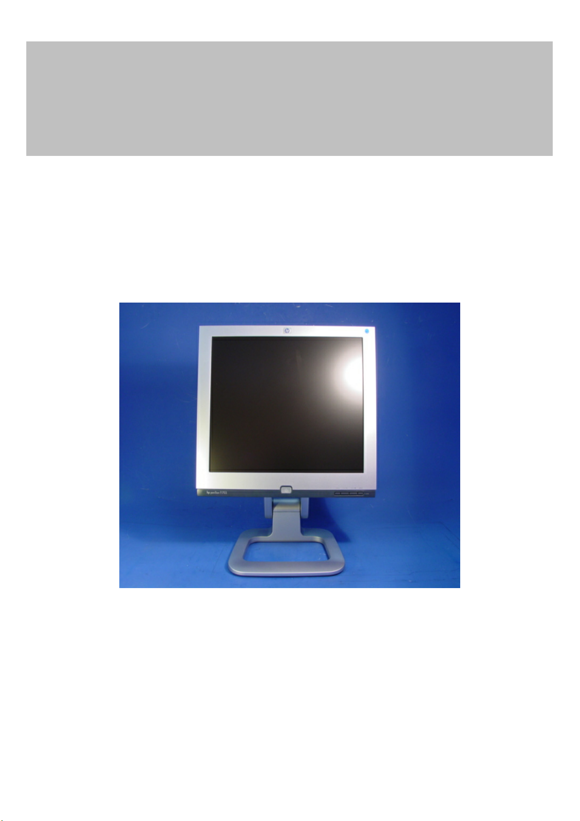
17” LCD Monitor
f1703
THESE DOCUMENTS ARE FOR REPAIR SERVICE INFORMATION ONLY. EVERY REASONABLE
EFFORT HAS BEEN MADE TO ENSURE THE ACCURACY OF THIS MANUAL; WE CANNOT
GUARANTEE THE ACCURACY OF THIS INFORMATION AFTER THE DATE OF PUBLICATION AND
DISCLAIMS RE LIABILITY FOR CHANGES, ERRORS OR OMISSIONS.
1
Page 2

HP f1703 Service Manual
Table of Contents
Table Of Contents --------------------------------------------------------------------------------------------------------------------2
1. Monitor Specifications ------------------------------------------------------------------------------------------------4
2. LCD Monitor Description ------------------------------------------------------------------------------------------------5
3. Operating Instructions ---------------------------------------------------------------------------------------------6
3.1 General Instructions -----------------------------------------------------------------------------------------------6
3.2 Control Buttons -----------------------------------------------------------------------------------------------------6
3.3 Adjusting the Picture -----------------------------------------------------------------------------------------------7
4. Input/Output Specification ----------------------------------------------------------------------------------------------------------8
4.1 Input Signal Connector ----------------------------------------------------------------------------------------------------------8
4.1.1 Analog D-SUB Connector ---------------------------------------------------------------------------------------------------8
4.2 Factory Preset Display Modes ---------------------------------------------------------------------------------------------------9
4.3 Power Supply Requirements -------------------------------------------------------------------------------------------------10
4.3.1 Input Requirements ------------------------------------------------------------------------------------------------------10
4.3.2 Output Requirements --------------------------------------------------------------------------------------------------------10
4.4 PANEL SPECIFICATION (Samsung) ------------------------------------------------------------------------------------11
4.4.1 Panel Feature --------------------------------------------------------------------------------------------------------------11
4.4.2 Display Characteristics --------------------------------------------------------------------------------------------------------11
4.4.3 Optical Characteristics -------------------------------------------------------------------------------------------------------11
4.4.4 Parameter Guide Line For CCFL Inverter ----------------------------------------------------------------------------12
5. Block Diagram -------------------------------------------------------------------------------------------------------------------13
5.1 Monitor Exploded View --------------------------------------------------------------------------------------------------------13
5.1.1 F1703 --------------------------------------------------------------------------------------------------------------------------13
5.2 Software Flow Chart --------------------------------------------------------------------------------------------------------------18
5.3 Electrical Block Diagram -----------------------------------------------------------------------------------------------------20
5.3.1 Main Board -------------------------------------------------------------------------------------------------------------------20
5.3.2 Inverter/Power Board -------------------------------------------------------------------------------------------------------21
6. Schematic ----------------------------------------------------------------------------------------------------------------------------22
6.1 Main Board -------------------------------------------------------------------------------------------------------------------22
6.2 Inverter/Power Board ------------------------------------------------------------------------------------------------------26
6.3 Keypad Board -------------------------------------------------------------------------------------------------------------------27
7. PCB Layout ---------------------------------------------------------------------------------------------------------------------------28
7.1 Main Board -------------------------------------------------------------------------------------------------------------------28
7.2 Inverter/Power Board ------------------------------------------------------------------------------------------------------29
7.3 Keypad Board ---------------------------------------------------------------------------------------------------------------------30
8. Maintainability ---------------------------------------------------------------------------------------------------------------------31
8.1 Equipments And Tools Requirement ------------------------------------------------------------------------------------31
8.2 Trouble Shooting -------------------------------------------------------------------------------------------------------------32
8.2.1 Main Board -------------------------------------------------------------------------------------------------------------------32
2
Page 3

HP f1703 Service Manual
8.2.2 Power/Inverter Board ------------------------------------------------------------------------------------------------------34
8.2.3 Keypad Board -------------------------------------------------------------------------------------------------------------37
8.3 Alignment Procedure -----------------------------------------------------------------------------------------------------38
8.4 EDIT Content --------------------------------------------------------------------------------------------------------------------39
8.5 Serial Number Format -------------------------------------------------------------------------------------------------------40
9. Part Lists --------------------------------------------------------------------------------------------------------------------------41
3
Page 4
HP f1703 Service Manual
1. MONITOR SPECIFICATIONS
Driving system TFT Color LCD
LCD Panel Size 43.2cm(17.0")
Pixel pitch 0.264mm( H )x 0.264mm( V )
Viewable angle 120˚ (H) 90˚ (V)
Response time (typ.) 25 ms
Video Analog
Input Sync. Type H/V TTL
H-Frequency 30kHz – 83kHz
V-Frequency 56-76Hz
Display Colors 16.2 million Colors
Dot Clock 108MHz
Max. Resolution 1280 x 1024
Plug & Play VESA DDC2BTM
Power Consumption ON Mode
(Speakers Connected)
ON Mode
(Without Speakers)
OFF Mode
(Audio Volume=0)
Maximum Screen Size
Power Source
Environmental
Operating Temp: 5°C to 35°C
<48W
<36W
<2W
Horizontal : 13.3”(337.92mm)
Vertical : 10.6”(270.336mm)
90~264VAC,47~63Hz
Considerations
Weight (N. W.)
F1703 5.5Kgs Unit (net)
Storage Temp.: -20°C to 60°C
Operating Humidity : 20% to 80%
4
Page 5

HP f1703 Service Manual
(
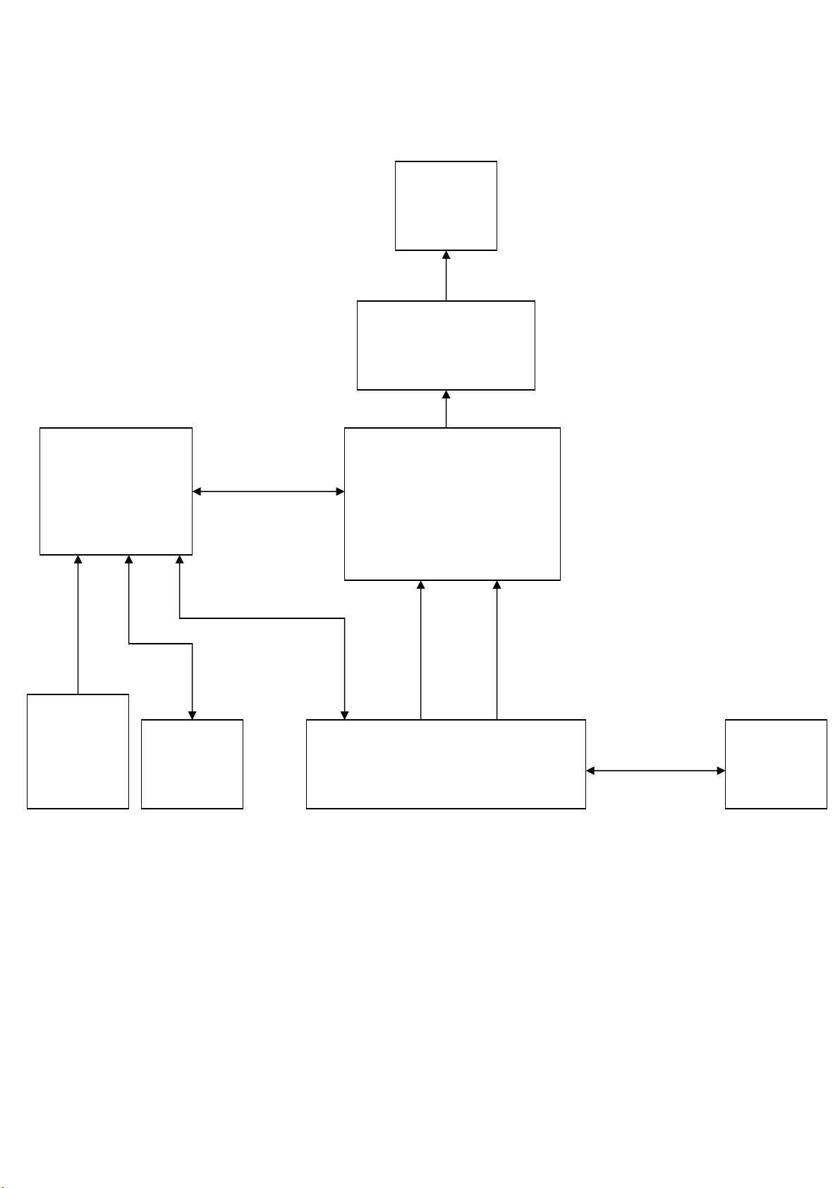
2. LCD MONITOR DESCRIPTION
The LCD MONITOR will contain an main board, an inverter/power board, keypad board and external adapter
which house the flat panel control logic, brightness control logic and DDC.
The Inverter board will drive the backlight of panel and the DC-DC conversion.
The Adapter will provides the 12V DC-power to inverter/power board.
AC-IN
90V-264V
Inverter Board
with DC-DC module)
ADAPTER
Monitor Block Diagram
CCFT Drive.
Main Board
Keyboard
Flat Panel and
CCFL backlight
HOST Computer
RS232 Connector
For white balance
adjustment in
factory mode
Video signal, DDC
5
Page 6
HP f1703 Service Manual
3. OPERATING INSTRUCTIONS
3.1 GENERAL INSTRUCTIONS
Press the power button to turn the monitor on or off. The other control buttons are located at front panel of the monitor. By changing
these settings, the picture can be adjusted to your personal preferences.
The power cord should be connected.
-
Connect the video cable from the monitor to the video card.
-
Press the power button to turn on the monitor, the power indicator will light up.
-
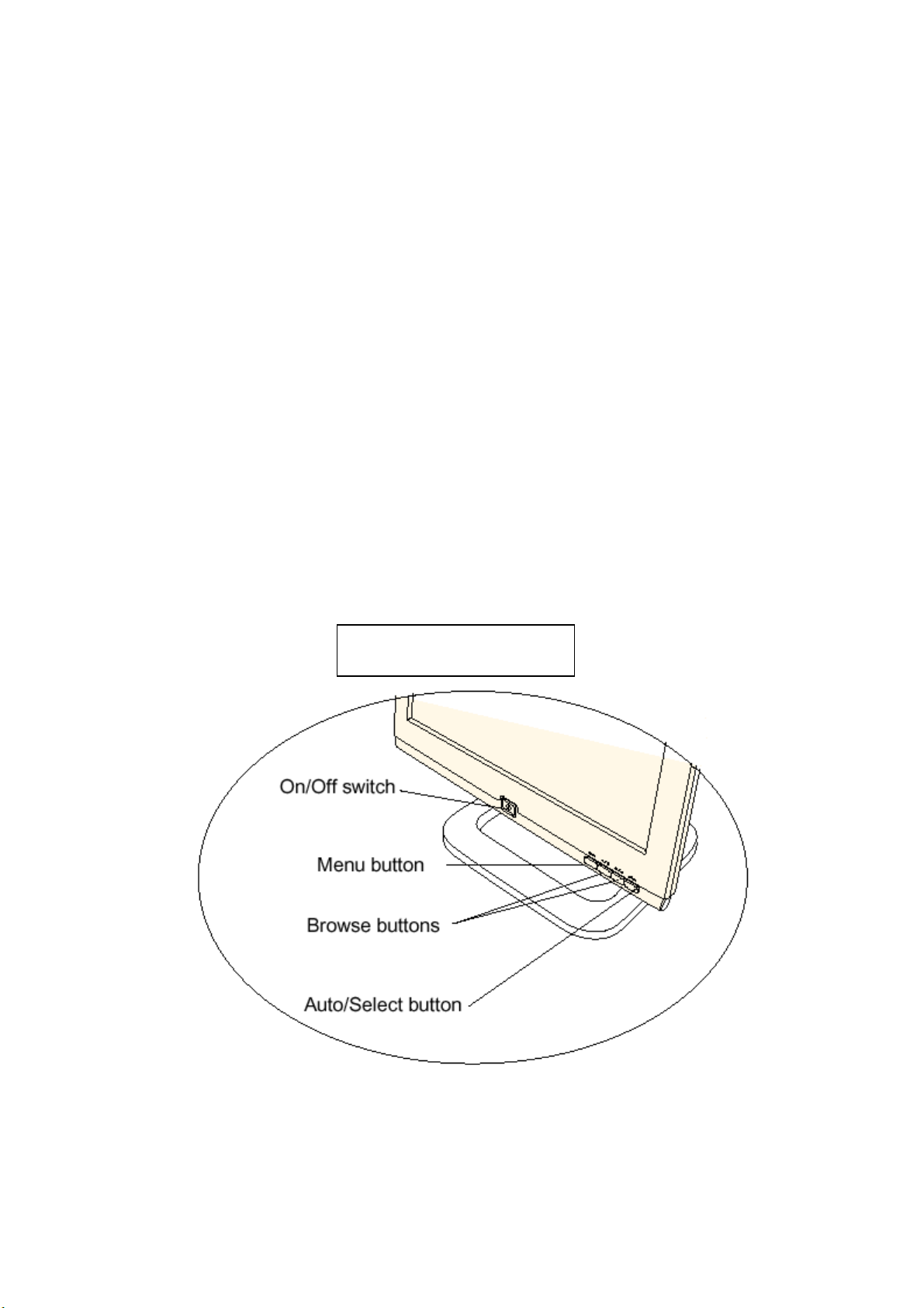
3.2 CONTROL BUTTONS
Power Button:
-
When pressed, the monitor enters the off mode, and the LED turns blank. Press again to restore normal status.
- Left / Right Button:
The Left/Right Button is used to control the monitor functions. Press to switch functions or adjust settings.
- Auto Adjust Key:
The Auto Adjust Key is used to automatically set the H Position, V Position, Clock and Phase.
- Power Indicator:
Blue — Power On mode.
Amber — Power Saving mode.
Blank —Power Off Mode.
CONTROL Buttons
6
Page 7
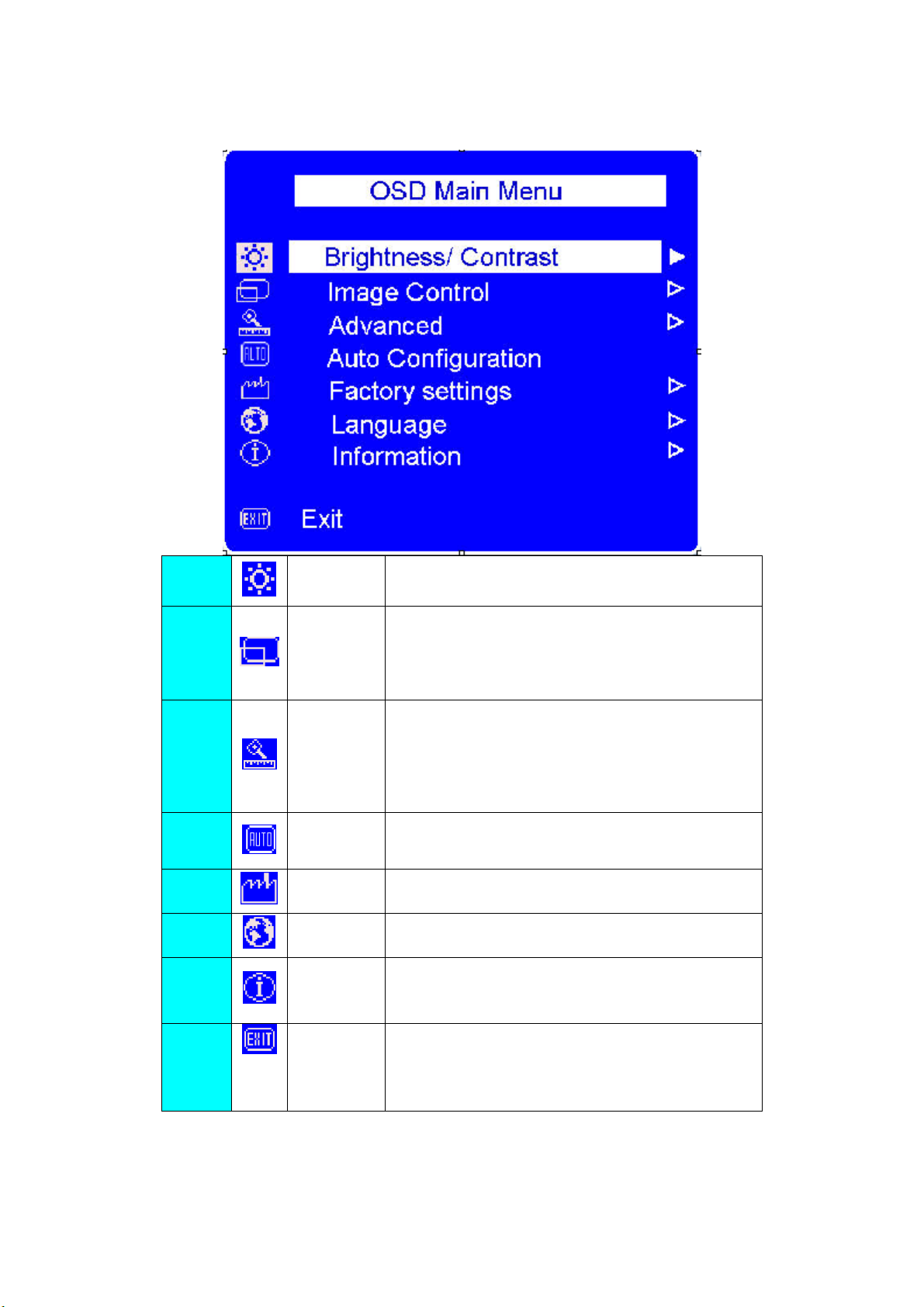
3.3 ADJUSTING THE PICTURE
HP f1703 Service Manual
1.
2.
Brightness/
Contrast
Image Control
3. Advance
Auto
4.
Configuration
5.
6.
Factory
settings
Language Shows the language of the OSD window.
7. Information
8.
Exit Closes the OSD window.
Adjust the brightness or the difference between the light and
dark area.
Adjust the:
z horizontal position of the screen image.
z vertical position of the screen image.
z frequency of the pixel clock to minimize vertical bar.
z phase value to minimize horizontal jitters.
Displays a sub-menu with two option:
z Color: adjusts the color tint of white, and the red,
green, and blue (RGB) mix for colors.
z OSD (on Screen Display) settings: adjusts the
position, timeout, and notification features of the On
Screen Display window.
Adjusts the main settings and produces a stable, centered
image.
Resets the display to original factory settings for color,
brightness, phase, and clock.
Shows the current resolution and refresh rate;
Shows the serial number of display; shows the power-on
time, and the power-saving time.
7
Page 8
4. Input/Outpt Specification
4.1 Input Signal Connector
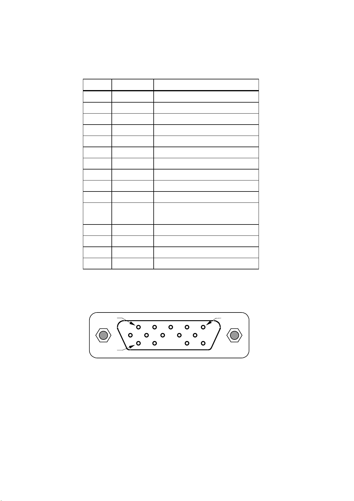
4.1.1 Analog D-SUB Connector
HP f1703 Service Manual
PIN
MNEMONIC
SIGNAL
1 RV Red Video
2 GV Green Video
3 BV Blue Video
4 NC
None (available for mfg use if required)
5 GND Ground (DDC Return)
6 RG Red GND
7 GG Green GND
8 BG Blue GND
9 +5 V +5 V (from PC)
10 SG Sync Ground
11 NC None (available for mfg use if
required)
12 SDA DDC Data
13 HS Horizontal Sync
14 VS Vertical Sync
15 SCL DDC Clock
VGA connector layout
PIN 1
PIN 11
PIN 5
8
Page 9
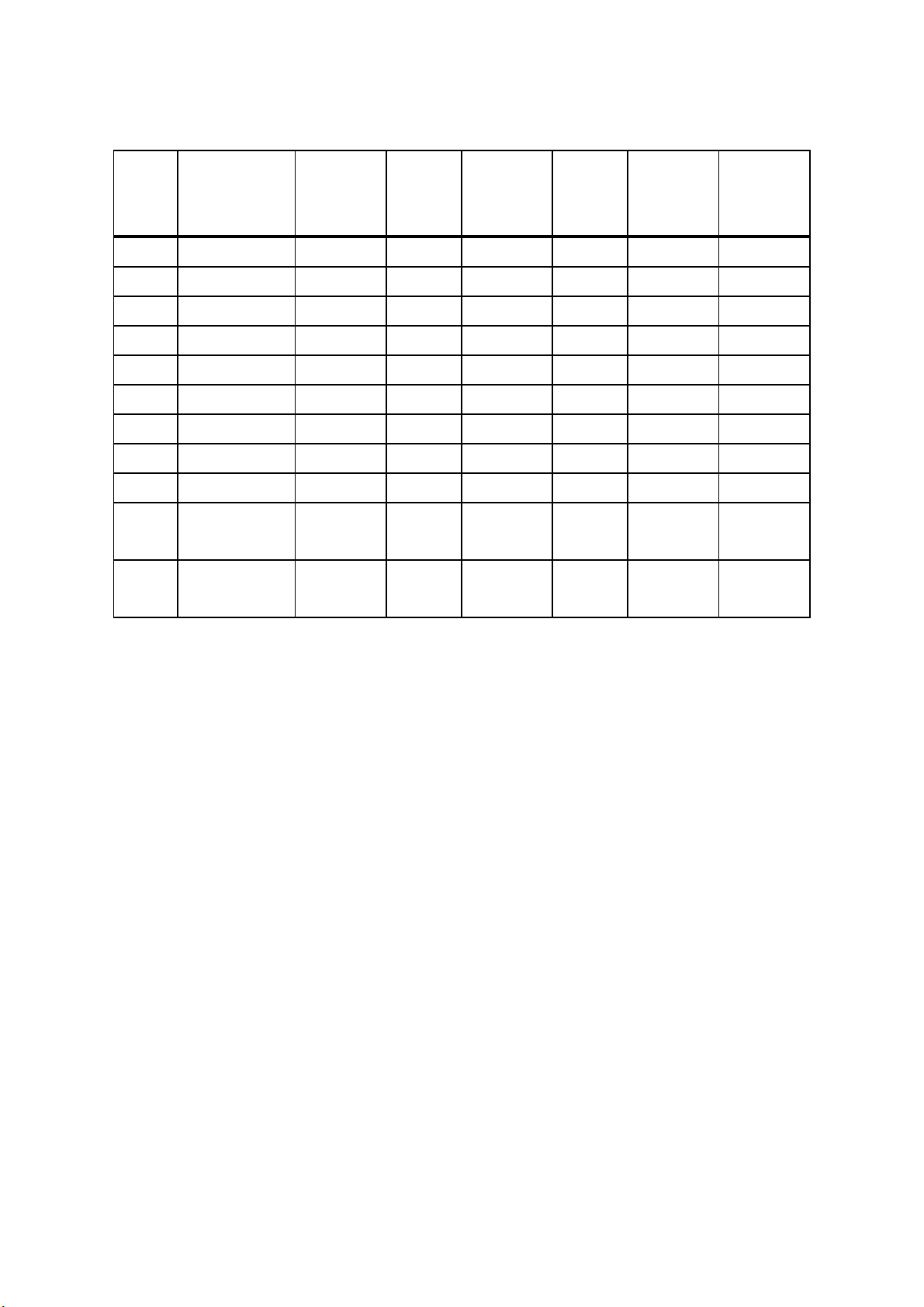
4.2 Factory Preset Display Modes
HP f1703 Service Manual
Prese
t
Pixel
Format
Horz
Freq
(KHz)
Horz
Polarit
y
Vert
Freq
(Hz)
Vert
Polarity Pixel Clk
(MHz) Source
1 640 x 350 31.469 + 70.086 - 25.175 VGA
2 640 x 480 31.469 - 59.940 - 25.175 VGA
3 640 x 480 37.500 - 75.000 - 31.500 VESA
4 720 x 400 31.469 - 70.087 + 28.322 VGA
5 800 x 600 37.879
+
60.317 + 40.000 VESA
6 800 x 600 46.875 + 75.000 + 49.500 VESA
7 1024 x 768 48.363 - 60.004 - 65.000 VESA
8 1024 x 768 56.476 - 70.069 - 75.000 VESA
9 1024 x 768 60.023 + 75.029 + 78.750 VESA
10
1280 x
63.981
+
60.02
+
108.0
VESA
1024
11
1280 x
79.976
+
75.035
+
135.0
VESA
1024
9
Page 10

HP f1703 Service Manual
d
)
p
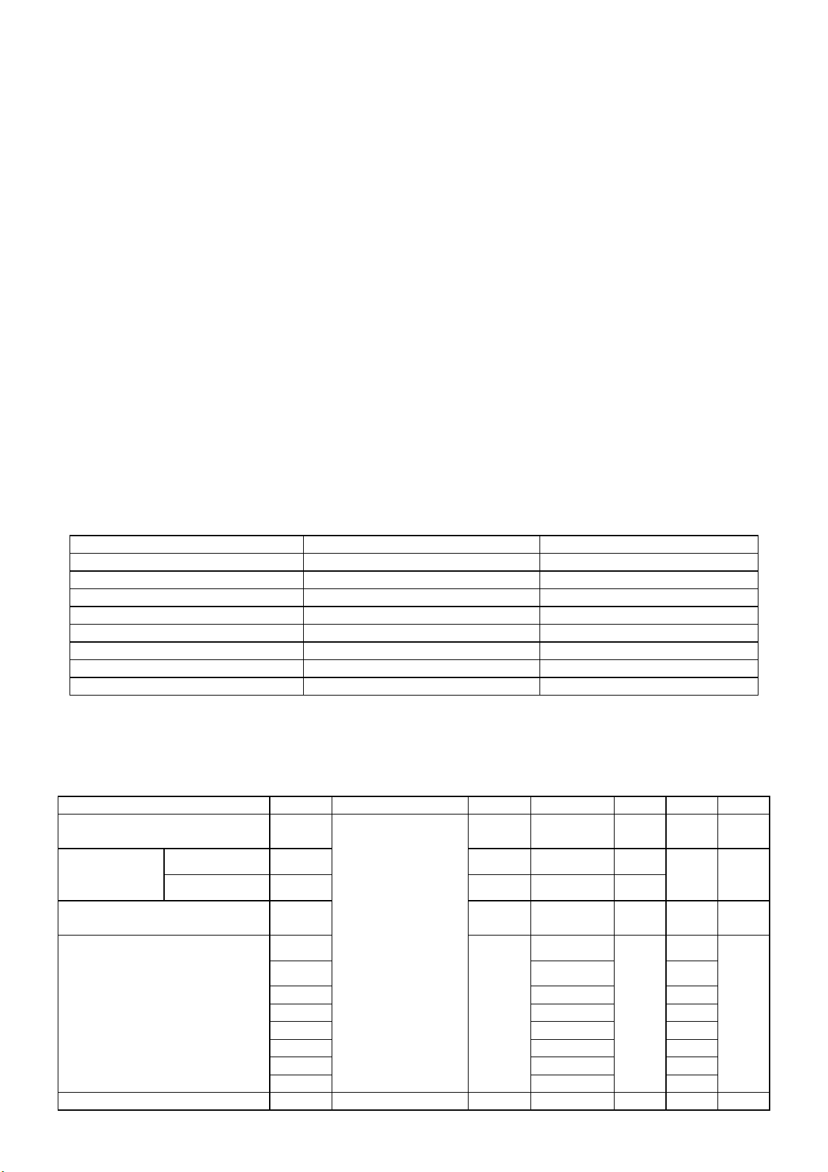
4.3 Power Supply Requirements
4.3.1 Input Requirements
PARAMETER RANGE CONDITION
Input Voltage 90 to 264 VAC RMS Universal input full range
Input Frequency 60Hz @ 90VAC to 50Hz @
264VAC
Input Current Less than 2.0 Amps RMS Input voltage 100 VAC RMS ; 60 Hertz. Parameter
must be reached within 3 seconds of turn-on.
Less than 1.0 Amps RMS Input voltage 220 VAC RMS ; 50 Hertz. Parameter
must be reachedwithin 3 seconds of turn-on.
Input Power Less than 75 Watts
Power factor > 0.5 Input voltage 120 VAC RMS ; 60
Hertz
Inrush Current Less than 30 A peak Input voltage 100 VAC RMS ; 60 Hertz at all
Less than 50 A peak Input voltage 240 VAC RMS ; 50 Hertz at all
Input Fusing Fuse should be located internal to the
adapter, easily accessible when the
cover is remove
Leakage Current Less than 3.5 mA Input voltage 264 Volts RMS ; 50 Hertz
Hi-Pot Primary to secondary 1.5KVAC for 1 Minute(leakage current 10mA)
Primary to Saft Ground 1.5KVAC for 1 Minute(leakage current 10mA)
Phase(0, 90, 180, 270 degree)
Phase(0, 90, 180, 270 degree)
Fuse must be UL/CSA approved. Fuse value must no
have to change for 115 VAC or 230 VAC operation
1.8KVAC for 1 Minute(leakage current 10mA)
3.0KVAC for 1 Minute(leakage current 10mA)
without Y-cap & Coupling cap.
1.8KVAC for 1 Minute(leakage current 10mA
4.3.2 Output Requirements
PARAMETER RANGE CONDITION
DC Out 12VDC ± 5% Min 0A Max 3.75A
Load Regulation 12.0V(12.12V) ± 5% 11.4 to 12.6VDC
Dynamic Load
Regulation
Ripple & noise 170mVpp at 12VDC Input voltage : 100VAC at 60Hz 240VAC at 50Hz
Output current
rotection
Leakage Current Less than 0.25 mA Input voltage 100 Volts RMS ; 50 Hertz
Less than 0.5 mA Input voltage 254 Volts RMS ; 50 Hertz
Any frequency up to 250Hz(duty
50%)
less than 7.0A, more than 12.0A
at 12.0VDC
±5% for 10% to 100%, 100% to 10% load change for
+12Vdc
* Ripple and noise are measured.
Current exceeds maximum rateing more than 20%
10
Page 11
4.4 PANEL SPECIFICATION (Samsung )
4.4.1 Panel Feature
-High contrast ratio, high aperture structure
-TN(Twisted Nematic) mode
-Wide viewing angle
-High speed response
-SXGA(1280 x 1024 pixels) resolution
-Low power consumption
-2 dual CCFTs(Cold Cathode Fluorescent Tube)
-DE(Data Enable) mode
-COMPACT SIZE DESIGN
HP f1703 Service Manual
4.4.2 Display Characteristics
Items Specification Unit
Display Area 337.92(H) x 270.336(V) mm
Driver element a-Si TFT active matrix
Display color 16.2M Colors
Number of pixels 1280 x 1024 pixel
Pixel Arrangement RGB vertical stripe
Pixel pitch 0.264(H) x 0.264(W) mm
Display Mode Normally White
Surface treament Haze 25% , Hard-coating (3H)
4.4.3 Optical Characteristics
The optical characteristics are measured under stable conditions at 25℃ (Room Temperature):
Item Symbol Conditions Min. Typ. Max. Unit Note
Contrast Ratio
(Center of screen)
Response
Time
Luminance of White
(Center of screen)
Chromaticity
Coordinates (CIE)
Brightness Uniformity [%] 75 80 -
Rising
Falling Tf - 20 25
Color
(CIE 1931)
C/R
Tr
YL 200 250 - Cd/m2
Rx
Ry 0.351
Gx 0.298
Gy 0.592
Bx 0.143
By 0.092
Wx 0.316
Wy 0.337
Normal
ψ=0
θ=0
Viewing
Angle
250 350 -
- 5 7
0.633
Typ.
-0.03
TYP.
+0.03
msec
11
Page 12

4.4.4 Parameter guide line for CCFL Inverter
INVERTER MAX BRINGTHNESS (Vadj:4.0v), LOAD=120KΩX4(ROOM TEMPERATURE 25℃ ±4℃)
ITEM
SYMBOL MIN. TYP. MAX. UNIT REMARK
HP f1703 Service Manual
Input voltage
10.8 12 13.2 V
Vin
Input current Iin 2300 2550 mA
Output Current Iout 6.0 6.5 7.0 mA
Frequency
H.V open
F 52.0
1500 1650 1800 Vrms
57.0 62.0 KHZ
Vopen
H.V Load
710 810 910 Vrms
Vload
Start voltage Vst
Protect delay time PDT
1700 1850 2000 Vrms
0.4 1 Sec
FOR 4 LOAD
FOR 1 LOAD
FOR 1 LOAD
NO LOAD
RL=120KΩ
RL=CCFL
12
Page 13
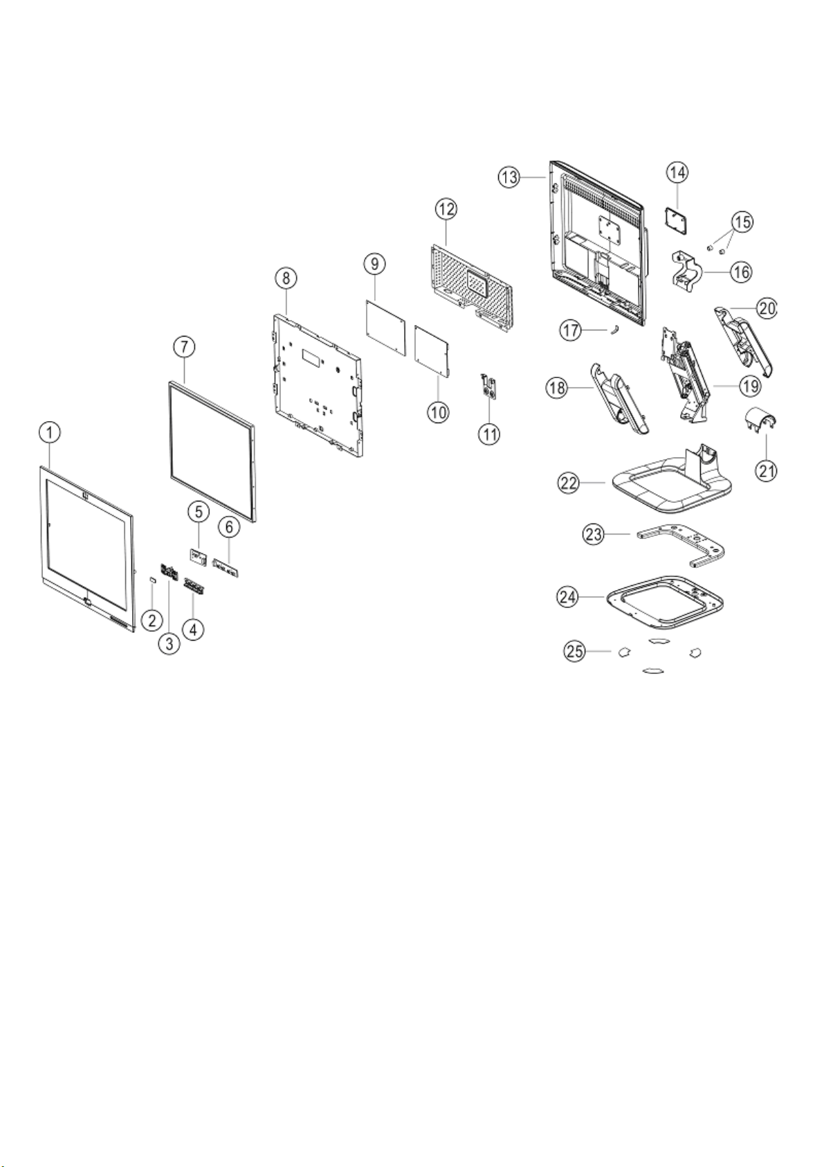
5. Block Diagram
5.1 Monitor Exploded View
5.1.1 f1703
HP f1703 Service Manual
13
Page 14
HP f1703 Service Manual
14
Page 15

HP f1703 Service Manual
15
Page 16
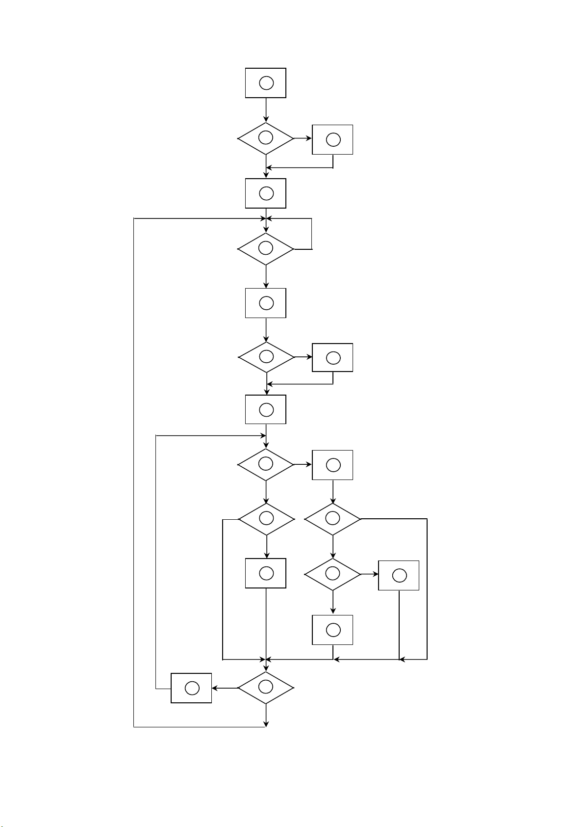
5.2 Software Flow Chart
2
10
12
643
8
9
141113
1516
1719
18
HP f1703 Service Manual
1
5
7
16
Page 17

HP f1703 Service Manual
1) MCU initialize.
2) Is the eeprom blank ?
3) Program the eeprom by default values.
4) Get the PWM value of brightness from eeprom.
5) Is the power key pressed ?
6) Clear all global flags.
7) Are the AUTO and SELECT keys pressed ?
8) Enter factory mode.
9) Save the power key status into eeprom.
Turn on the LED and set it to green color.
Scaler initialize.
10) In standby mode ?
11) Update the life time of back light.
12) Check the analog and digital port, are there any signals coming ?
13) Does the scalar send out a interrupt request ?
14) Wake up the scalar.
15) Are there any signals coming from analog or digital port ?
16) Display "Check Video Cable" message. And go into standby mode after the message
disappear.
17) Program the scalar to be able to show the coming mode.
18) Process the OSD display.
19) Read the keyboard. Is the power key pressed ?
17
Page 18
5.3 Electrical Block Diagram
5.3.1 Main Board
HP f1703 Service Manual
MCU
W78E65P
(U8)
ADE_SDA,
ADE_SCL
LCD
Interface
(CN3)
LVDS
THC63LVDM83A
(U2)
Scalar ADE3000SX
(Include ADC,OSD)
(U1)
OSD
Control
Interface
(CN1)
EPR_SDA
EPR_SCL
EEPROM
24C16
(U9)
RXD
TXD
RGB
D-Sub
Connector
(CN1)
Hsync,
Vsync
DB15_SDA,
DB15_SCL
EEPROM
24C02
(U2)
18
Page 19

5.3.2 Inverter/Power Board
HP f1703 Service Manual
Inverter Block Diagram
Vin
Vin
Buck Connector
Driver
Circuit
Driver
Circuit
Dimming control
Parallet-resonant
inverter
Dimm ing control
(PW M )
(阀菠瓜)
Parallet-resonant
inv erter
CCFL
PWM
+12V
Power Block Diagram
PWM
BA9741
(U101) Output1
PWM
BA9741
(U101) Output2
AIC1084CM
+5V
+3.3V
+1.8V
19
Page 20

6. Schematic
6.1 Main Board
HP f1703 Service Manual
CONTENTS
SCHEMATIC
Title Page
ADE3200
Input Interface
Damping Resister
Output Interface
8051 Microcontroller
Board Power Supply
SHEET
1
2
3
4
5
6
7
715L-1006-1
ADE3000SX 17" LCD Control Board Rev.G
Mannequin 17"
Title
Size Document Number Rev
Date: Sheet of
星期一, 三月
ADE3000 LCD Control Board
Title Page & circuit block
24, 2003
18
0.1
20
Page 21

HP f1703 Service Manual
AVDD_1.8
12
+
C1
22uF/16V
RV2_6
C39
22uF/16V
RV2_6
DVDD_1.8
Distribute the 4 resisters arround the
top of AGND plane.
10uF/6.3V
12
+
10uF/6.3V
AVDD_1.8
FB7
60OHM
REFCR
REFR
R1
15K 1/16W
0.1uF/16V
REFCG
REFG
R3
15K 1/16W
0.1uF/16V
REFCB
REFB
R5
15K 1/16W
0.1uF/16V
INTERNAL ADC REFERENCE
RESISTORS AND DECOUPLING
CAPACITORS. PLACE THESE
COMPONENTS CLOSE TO THEIR
RESPECTIVE PINS
DVDD_3.3
R138 0 1/16W
R139 0 1/16W
R140 0 1/16W
R141 0 1/16W
C3
1206
AVDD_3.3
C49
1206
C60
C63
C66
FB6
60OHM
C5
C4
0.1uF/16V
0.1uF/16V
C51
C50
0.1uF/16V
0.1uF/16V
PLACE CAPACITORS ON PINS 14,
38, AND 42, RESPECTIVELY
(TMDS power supply pins)
REFPR
C58
R2
0.47uF/16V
NP
REFPG
C61
R4
0.47uF/16V
NP
REFPB
C64
R6
0.47uF/16V
NP
AVDD_3.3
C130
0.1uF/16V
C6
C7
0.1uF/16V
0.1uF/16V
C52
C53
0.1uF/16V
0.1uF/16V
C59
100pF
REFMR
C62
100pF
REFMG
C65
100pF
RVDD_3.3
REFMB
same lenth,and
parallel
The OCLK should have third
priority and be shielded with GND.
(short,straight connection on top
layer only)
0.1uF/16V
INR(3)
ING(3)
INB(3)
AVDD_1.8
C55
FB4
60OHM
no via, same
layer
0.1uF/16V
ADE-RESET#(6)
AHSYNC(3)
AVSYNC(3)
FB2
60OHM
FB3
60OHM
RVDD_1.8
C56
Close to U1
C75 0.1uF/16V
C76 0.1uF/16V
C77 0.1uF/16V
C67
0.1uF/16V
ADE-SCL(6)
ADE-SDA(6)
FB1
60OHM
XVDD_1.8
LVDD_1.8
C57
0.001uF
R19
R22
R24
R7
475 1/16W(NC)
2K 1/16W(NC)
DVDD_3.3
C71
10pF
C37
0.1uF/16V
C54
0.1uF/16V
R8
TP2
TP4
TP6
TP8
TP10 1
R12
1M(NC)
27MHz
C11
0.1uF/16V
10 1/16W
10 1/16W
10 1/16W
TP1
1
TP3
1
TP5
1
TP7
1
TP9
C68 0.001uF
Y1
PVDD_1.8
C12
0.1uF/16V
REFR
REFCR
REFPR
REFMR
REFG
REFCG
REFPG
REFMG
REFB
REFCB
REFPB
REFMB
1
YUV0
YUV1
1
YUV2
YUV3
1
YUV4
YUV5
YUV6
1
YUV7
1
YUVCLK
R9
4.7K 1/16W
R10 0 1/16W
C72
15pF
AVDD_3.3
C14
C13
0.01uF
0.1uF/16V
100pF
PLACE CAPACITORS C14, C15, C16, C17, C18,
C19, AND C20 ON PINS 15, 19, 22, 25, 29, (31 &
32), AND 40, RESPECTIVELY
(TMDS power supply pins)
DVDD_1.8
9
121
123
140
142
164
166
U1
DVDD18
DVDD18
DVDD18
DVDD18
DVDD18
DVDD18
92
INR
80
ING
68
INB
55
HSYNC
54
VSYNC
53
CSYNC
183
CLKIN
87
REFR
95
REFCR
89
REFPR
88
REFMR
75
REFG
83
REFCG
77
REFPG
76
REFMG
63
REFB
71
REFCB
65
REFPB
64
REFMB
16
RX2M
17
RX2P
20
RX1M
21
RX1P
23
RX0M
24
RX0P
27
RXCP
28
RXCM
30
REXT
36
RBIAS
7
YUV0
6
YUV1
5
YUV2
4
YUV3
3
YUV4
2
YUV5
1
YUV6
208
YUV7
8
YUVCLK
203
SCL
204
SDA
207
RESETN
184
TCON_IN
206
XCLK_EN
99
TST_SCAN
48
XTAL_IN
49
XTAL_OUT
DGND
DGND
DGND
DGND
DGND DVDD18
DGND
10 11
12
100
105
112
122
124
C2
22uF/16V
RV2_6
C38
22uF/16V
RV2_6
58596970818293
AVDD33
AVDD33
AVDD33
AVDD33
AGND
AGND
AGND
AGND
DVDD_1.8
C20
10uF/6.3V
1206
DVDD_3.3
C40
10uF/6.3V
1206
RVDD_1.8
143842
94
AVDD33
AVDD33
AVDD33
AVDD33
RVDD18
RVDD18
RVDD18
RGND
RGND
RGND
RGND
RGND
RGND
RGND
AGND
1318263334353739414345
RVDD_3.3
15192225293132
RVDD33
RVDD33
RVDD33
RVDD33
RGND
RGND
PGND
C21
10uF/6.3V
1206
C41
0.1uF/16V
RVDD33
RVDD33
PGND
PVDD_1.8
40
RVDD33
RVDD33
XGND
47
R13 0 1/16W
0.1uF/16V
44
PVDD18
C42
46
C22
10uF/6.3V
1206
C182
1uF/16V
51
PVDD18
LVDD18
CLKOUT
0.1uF/16V
LVDD_1.8
50
XVDD18
ORA0
ORA1
ORA2
ORA3
ORA4
ORA5
ORA6
ORA7
OGA0
OGA1
OGA2
OGA3
OGA4
OGA5
OGA6
OGA7
OBA0
OBA1
OBA2
OBA3
OBA4
OBA5
OBA6
OBA7
ORB0
ORB1
ORB2
ORB3
ORB4
ORB5
ORB6
ORB7
OGB0
OGB1
OGB2
OGB3
OGB4
OGB5
OGB6
OGB7
OBB0
OBB1
OBB2
OBB3
OBB4
OBB5
OBB6
OBB7
OCLK
TCON0
TCON1
TCON2
TCON3
TCON4
TCON5
TCON6
TCON7
XCLK
LGND
52
C24
C23
C25
0.1uF/16V
0.1uF/16V
0.1uF/16V
C45
C44
C43
0.1uF/16V
0.1uF/16V
XVDD_1.8
C184
C183
1uF/16V
1uF/16V
ORB0
133
ORB1
132
ORB2
131
ORB3
130
ORB4
129
ORB5
128
127
ORB6
126
ORB7
OGB0
120
OGB1
119
OGB2
118
OGB3
117
OGB4
116
115
OGB5
114
OGB6
113
OGB7
110
OBB0
109
OBB1
108
OBB2
107
OBB3
106
OBB4
104
OBB5
103
OBB6
OBB7
102
ORA0
177
ORA1
176
ORA2
175
174
ORA3
171
ORA4
ORA5
170
169
ORA6
ORA7
168
OGA0
163
OGA1
162
161
OGA2
160
OGA3
157
OGA4
156
OGA5
OGA6
155
OGA7
154
OBA0
153
152
OBA1
151
OBA2
150
OBA3
147
OBA4
OBA5
146
145
OBA6
OBA7
144
138
136
ODE
137
OHS
139
OVS
TCON0
198
TCON1
197
TCON2
196
TCON3
195
TCON4
190
TCON5
189
TCON6
188
TCON7
187
205
C69
182
NP_C
LVDD_1.8
C73
0.1uF/16V
C28
C30
C26
0.1uF/16V
C46
0.1uF/16V
R11 0 1/16W
C29
C27
0.1uF/16V
0.1uF/16V
C47
0.1uF/16V
ORB[7:0] (4)
OGB[7:0] (4)
OBB[7:0] (4)
ORA[7:0] (4)
OGA[7:0] (4)
OBA[7:0] (4)
OCLK (5)
ODE (5)
OHS (5)
OVS (5)
TCON[7:0] (5)
The TCON[0..7], ODE, OHS and
OVS are the fourth priority.
MCU-CLK
C70
NP_C
C31
0.1uF/16V
0.1uF/16V
0.1uF/16V
C48
0.1uF/16V
MCU-CLK (6)
AOC
Title
ADE3000 LCD Control Board
Size Document Number Rev
ADE3000
Date: Sheet
0.1uF/16V
C32
C35
C34
C33
0.1uF/16V
0.1uF/16V
0.1uF/16V
every 8 signal = one group
same lenth and parallel in
one group , shielding with
GND in one group , put
via on GND
28Monday, January 27, 2003
C36
0.1uF/16V
0.1
of
RVDD_3.3
12
C15
178
180
DVDD18
DVDD18
C18
C16
C17
0.01uF
0.1uF/16V
0.001uF
DVDD_3.3
191
193
199
201
101
111
125
134
148
158
DVDD18
DVDD18
DVDD18
DVDD18
DVDD18
DVDD33
DVDD33
DVDD33
DVDD33
DVDD33
172
DVDD33
AVDD_1.8
185
DVDD33
DVDD33
C19
0.01uF
61737485869798
AVDD18
AVDD18
+
12
+
AVDD_3.3
AVDD18
AVDD18
AVDD18
AVDD18
AVDD18
ADE3000SX
DGND
DGND
DGND
DNGD
DGND
DGND
DGND
DGND
DGND
DGND
DGND
DGND
DGND
DGND
DGND
DGND
AGND
AGND
AGND
AGND
AGND
AGND
AGND
135
141
143
149
159
165
167
173
179
181
186
192
194
200
202
56576062666772787984909196
AGND
21
Page 22

HP f1703 Service Manual
3.3K 1/16W
R14
1
BAT54C
2
3
TZMC5V6-GS08
+5V
3 2
0.1uF/16V
R15
3.3K 1/16W
ZD2
BAT54CFILM
C74
SOD123
VGA_5V
D1
D2
1
DIODE_23(NP)
1 2
D3
BAV99
23
1
ED3
ED2
DIODE_23(NP)
1 2
1 2
13 12
11 10
U2
1
SOD123
10K 1/16W
ZD3
TZMC5V6-GS08
8
VCC
7
6
SCL
5
SDA
M24C02WMN6
R28
A0
A1A2WP
GND
DDC-SCL (6)
DDC-SDA (6)
ZD4
SOD123
2
3
4
R168
47 1/16W
R169
47 1/16W
ZD5
R29
10K 1/16W
TZMC5V6-GS08
TZMC5V6-GS08
SOD123
10K 1/16W
A-DETECT(6)
R16
RXD(6)
DB15_SDA
DB15-AHSYNC
DB15-AVSYNC
DB15_SCL
+5V
VGA_5V
Analog Input (VGA)
TXD(6)
CN1
DB15
1
9
2
10
3
11
4
12
5
13
6
14
7
15
8
16
17
1
RED
GREEN
BLUE
BAV99
trace 16mil
ED1
DIODE_23(NP)
23
150 1/16W
147
147
5 6
147
+5V
147
9 8
D4
BAV99
1
150 1/16W
R25
R172
U3F
74F14
DB15-AVSYNC
U3C
74F14
DB15-AHSYNC
U3E
74F14
C86
0.1uF/16V
U3D
74F14
AVDD_3.3
23
150 1/16W
BAV99
3
150 1/16W
R173
R26
R167
0 1/16W
R151
0 1/16W
Shielding with GND
CLOSE TO CN1
1
2
150 1/16W
150 1/16W
R27
R174
C188
47pF
C185
47pF
R18 120 1/16W
R21 120 1/16W
R23 120 1/16W
10pF(NC)
147
3 4
147
1 2
Highest Priority to input RED, GREEN, BLUE and A_HSYNC (from
CON3 to U1). The route width of RED, GREEN, BLUE and A_HSYNC
should be larger than 16 mils. The signals should be on the top layer
with no via, the length is less than 5 cm for better picture quality
(short,
straight connection on top layer).
C78
C79
10pF(NC)
10pF(NC)
R30
U3B
33 1/16W
74F14
R31
U3A
33 1/16W
74F14
INPUT INTERFACE
FB18 60 OHM
FB19 60 OHM
FB20 60 OHM
C80
trace 16 mils (minimum)
C189
NP_C
C83
27pF
AVSYNC (2)
AHSYNC (2)
Shielding with GND
INR (2)
ING (2)
INB (2)
AOC
Title
Size Document Number Rev
Date: Sheet of
星期一, 三月
ADE3000 LCD Control Board
Input Interface
24, 2003
38
0.1
OUTPUT INTERFACE
ORA[7:0](2,5)
OGA[7:0](2,5)
OBA[7:0](2,5)
ORA0
ORA1
ORA2
ORA3
ORA6
ORA5
ORA4
OGA0
OGA1
OGA3
OGA4
OGA5
OGA6
OGA7
OBA0
OBA1
OBA2
OBA3
OBA4
OBA5
OBA6
OBA7
RA0
RA1
RA2
RA3
RA7ORA7
RA6 RB6
RA5
RA4
GA0
GA1
GA2
GA3
GA4
GA5
GA6
GA7
BA0
BA1
BA2
BA3
BA4
BA5
BA6
BA7
RA[7:0] (2,5)
GA[7:0] (2,5)
BA[7:0] (2,5)
ORB[7:0](2,5)
OGB[7:0](2,5)
OBB[7:0](2,5)
ORB0
ORB1
ORB2
ORB3
ORB7
ORB6
ORB5
ORB4
OGB0
OGB1
OGB2OGA2
OGB3
OGB4
OGB5
OGB6
OGB7
OBB0
OBB1
OBB2
OBB3
OBB4
OBB5
OBB6
OBB7
RB0
RB1
RB2
RB3
RB7
RB5
RB4
GB0
GB1
GB2
GB3
GB4
GB5
GB6
GB7
BB0
BB1
BB2
BB3
BB4
BB5
BB6
BB7
RB[7:0] (2,5)
GB[7:0] (2,5)
BB[7:0] (2,5)
R46 0 1/16W
OVS
OVS(2)
OHS
OHS(2)
ODE
ODE(2)
OCLK R49 X 1/16W
OCLK(2)
R47 0 1/16W
R48 0 1/16W
C145
NP_C
C88
NP_C
C89
NP_C
C90
NP_C
C91
NP_C
PVS
PVS (5)
PHS
PHS (5)
PDE
PDE (5)
PCLK
PCLK (5)
AOC
Title
Size Document Number Rev
Date: Sheet of
星期一, 三月
ADE3000 LCD Control Board
Output Interface
24, 2003
48
0.1
22
Page 23

HP f1703 Service Manual
LCD_+A5V
LCD_+5V
彩絬 ぶ
30mils
12
+
0.1uF/16V
EDGE
GND
GND
GND
GND
GND
FB12
120OHM
EDGE
GND
GND
GND
GND
GND
C100
22uF/16V
RV2_6
C94
LCD_+A3.3V
12
+
C101
22uF/16V
RV2_6
120OHM
+
C92
22uF/16V
32
48
TX0-E
47
TX0+E
TX1-E
46
45
TX1+E
42
TX2-E
41
TX2+E
38
TX3-E
37
TX3+E
40
TXCK-E
39
TXCK+E
44
49
C95
43
22uF/16V
36
34
35
C97
33
22uF/16V
53
29
21
13
5
DVDD_3.3
32
48
TX0-O
TX0+O
47
TX1-O
46
45
TX1+O
TX2-O
42
TX2+O
41
TX3-O
38
37
TX3+O
40
TXCK-O
39
TXCK+O
44
49
C103
43
22uF/16V
36
34
35
C105
33
22uF/16V
53
29
21
13
5
R133
0 1/16W
R146
NP_R
R148
NP_R
1
2
3
4
1
V
1
91726
V
U7
S1
G1
S2
G2
P-MOS
STS3DPF30L
91726
V
V
V
V
D1
D1
D2
D2
FB9
60OHM
8
7
6
5
C93
0.1uF/16V
TXCLKOUT-
TXCLKOUT+
C99
0.1uF/16V
PWRDWN
TXCLKOUTTXCLKOUT+
LVDSVCC
LVDSGND
LVDSGND
LVDSGND
PWRDWN
TXOUT0-
TXOUT0+
TXOUT1-
TXOUT1+
TXOUT2-
TXOUT2+
TXOUT3-
TXOUT3+
LVDSVCC
LVDSGND
LVDSGND
LVDSGND
PLLVCC
PLLGND
PLLGND
TXOUT0TXOUT0+
TXOUT1TXOUT1+
TXOUT2TXOUT2+
TXOUT3TXOUT3+
PLLVCC
PLLGND
PLLGND
LCD_+3.3V
LCD_+5V
R132
NP
R50
C147
10K 1/16W
ODD
0.1uF/16V
Q3
PMBS3904
+
C176
4.7uF/16V
0 1/16W
R147
U5
NT7181FQ
51
TXIN0
52
TXIN1
54
TXIN2
55
TXIN3
56
TXIN4
3
TXIN6
50
TXIN27
2
TXIN5
4
TXIN7
6
TXIN8
7
TXIN9
11
TXIN12
12
TXIN13
14
TXIN14
8
TXIN10
10
TXIN11
15
TXIN15
19
TXIN18
20
TXIN19
22
TXIN20
23
TXIN21
24
TXIN22
16
TXIN16
18
TXIN17
25
TXIN23
27
TXIN24
28
TXIN25
30
TXIN26
31
TXCLKIN
0 1/16W
R149
U6
NT7181FQ
51
TXIN0
52
TXIN1
54
TXIN2
55
TXIN3
56
TXIN4
3
TXIN6
50
TXIN27
2
TXIN5
4
TXIN7
6
TXIN8
7
TXIN9
11
TXIN12
12
TXIN13
14
TXIN14
8
TXIN10
10
TXIN11
15
TXIN15
19
TXIN18
20
TXIN19
22
TXIN20
23
TXIN21
24
TXIN22
16
TXIN16
18
TXIN17
25
TXIN23
27
TXIN24
28
TXIN25
30
TXIN26
31
TXCLKIN
3
R56 10K 1/16W
1
B
MMBT3904
2
E
PWSVLCD(6)
EVEN
RA[7:0](2)
GA[7:0](2)
BA[7:0](2)
PCLK(4)
RB[7:0](2)
GB[7:0](2)
BB[7:0](2)
PHS(4)
PVS(4)
PDE(4)
PCLK(4)
RA0
RA1
RA2
RA3
RA4
RA5
RA6
RA7
GA0
GA1
GA2
GA3
GA4
GA5
GA6
GA7
BA0
BA1
BA2
BA3
BA4
BA5
BA6
BA7
RB0
RB1
RB2
RB3
RB4
RB5
RB6
RB7
GB0
GB1
GB2
GB3
GB4
GB5
GB6
GB7
BB0
BB1
BB2
BB3
BB4
BB5
BB6
BB7
PHS
PVS
PDE
PCLK
LCD_+3.3V
FB10
60OHM
VLCD
LCD_DDON
C102
0.1uF/16V
R134
10K 1/16W
FB13
DVDD_3.3
TXE0
TXE1
Same
TXE2
length
TXE3
TXE4
TXE5
TXE6
TXE7
TXE8
TXE9
+
0.01uF
+
0.01uF
TXO0
TXO1
TXO2
TXO3
TXO4
TXO5
TXO6
TXO7
TXO8
TXO9
+
C104
0.01uF
+
C106
0.01uF
C96
C98
Same
length
120OHM
120OHM
120OHM
120OHM
FB16
FB17
DVDD_3.3
FB14
FB15
LVDS_EN (6)
DVDD_3.3
TXE0
TXE2
TXE4
TXE8
TXE6
TXO0
VLCD
TXO2
TXO4
TXO8
TXO6
TX0-E
TX1-E
TX2-E
TXCK-E
TX3-E
TX0-O
TX1-O
TX2-O
TXCK-O
TX3-O
CN3
CONN
TXE1
TX0+E
12
TX1+E
TXE3
34
TX2+E
TXE5
56
TXCK+E
TXE9
78
TXE7
TX3+E
910
TX0+O
TXO1
1112
TXO3
TX1+O
1314
TXO5
TX2+O
1516
TXO9
TXCK+O
1718
TX3+O
TXO7
1920
2122
2324
OUTPUT INTERFACE
AOC
Title
ADE3000 LCD Control Board
Size Document Number Rev
Output Interface
Date: Sheet
星期一, 三月
24, 2003
C186
0.1uF/16V
1
1
1
1
1
1
BRIGHTNESS
1
RESET
R170 47 1/16W
R171 47 1/16W
R157 47 1/16W
R158 47 1/16W
R159 47 1/16W
R160 47 1/16W
R17 47 1/16W
R20 47 1/16W
R80
1M(NC)
Y2
20MHz
+5V
C115
0.1uF/16V
+5V
2
1
LM810(NC)
SOT23-3
8051 MICROCONTROLLER
+5V
R65
JP4
10K 1/16W
R0603
1
0
R89
1K 1/16W
1K 1/16W
星期一, 三月
PMBS3906
PMBS3906
R97
PANELID0
R68
NC
R0603
DEBUGGER
+5V
Q6
+5V
Q7
ADE3000 LCD Control Board
8051 Microcontroller
24, 2003
JP4
1
2
NP
JUMP ON: DEBUG MODE
JUMP OFF: NORMAL
R83
1K 1/16W
R135
1K 1/16W
R91
1K 1/16W
R136
1K 1/16W
+5V
R156
10K 1/16W
R0603
LED-GRN
JP1
1
2
NP
LED-ORG
68
1
MMBT3904
3
R87
47K 1/16W
+5V
PWSVLCD (5)
8
7
6
5
2
C111
0.1uF/16V
+5V
+5V
B-LED1
O-LED1
ON/OFF
SEL
RIGHT
LEFT
AUTO
Q5
PMBS3904
LV-DETECT
R88
1K 1/16W
R66
200K 1/16W
LVDS_EN (5)
ADE-RESET# (2)
SEC
HDY
0 : JUMP ON
1 : JUMP OFF
ゅ
B-LED1
O-LED1
AOC
Title
U11
VCC
3
R152
0 1/16W(NC)
C187
0.1uF/16V(NC)
GND
22
RESET
8XC51/PLCC
P2.0/A8
P2.1/A9
P2.2/A10
P2.3/A11
P2.4/A12
P2.5/A13
P2.6/A14
P2.7/A15
PSEN
ALE/PROG
P0.7/AD7
P0.6/AD6
P0.5/AD5
P0.4/AD4
P0.3/AD3
P0.2/AD2
P0.1/AD1
P0.0/AD0
EA/VP
NCNCNC
11223
R82
10K 1/16W
ZD1
MLL740A
R86
NP
ON/OFF
24
25
SEL
RIGHT
26
LEFT
27
28
AUTO
LV-DETECT
29
PANELID0
30
A-DETECT
31
32
33
36
37
38
39
40
41
42
43
44
VCC
35
NC
34
DEBUGGER
EPR_EN
LVDS_EN
ADE-RESET#
PWSVLCD
BLON
LED-ORG
LED-GRN
R142
3.3K 1/16W
C109
0.1uF/16V
A-DETECT (3)TP17
BLON (7)
+5V
R63
10K 1/16W
RESET
GND
3
LM810
2
1
U8
2
T2/P1.0
3
T2EX/P1.1
4
P1.2
5
P1.3
6
P1.4
7
P1.5
8
P1.6
9
P1.7
10
RST
11
RXD/P3.0
13
TXD/P3.1
14
INT0/P3.2
15
INT1/P3.3
16
TO/P3.4
17
T1/P3.5
18
WR/P3.6
19
RD/P3.7
20
XTAL2
21
XTAL1
C114
33pF
CN5
1
2
CONN
3
4
5
6
7
8
9
CP13
1000 pF
4327
5
6
1
8
R161 4.7K 1/16W
1
2
3
4
RP13 4.7K 1/16W
C174
1000pF/16V
Size Document Number Rev
Date: Sheet of
+5V
D20
C173
1N4148
2.2 uF
R131
3.3K
CN9
1
2
3
4
R74
3.3K 1/16W
+5V
47 1/16W
+5V
R73
3.3K 1/16W
ADE-SCL(2)
ADE-SDA(2)
R153
RESET
1 2
0 1/16W
TP11
TP12
TP13
TP14
TP15
TP16
BRIGHTNESS(7)
R155
R154
47 1/16W
RXD
RXD(3)
TXD
TXD(3)
EPR-SDA
EPR-SCL
DDC-SDA(3)
DDC-SCL(3)
R78 0 1/16W(NC)
MCU-CLK(2)
C113
33pF
+5V
R85
3.3K 1/16W
EPR-SCL
EPR-SDA
R145
4.7K 1/16W
EPR_EN
R84
+5V
3.3K 1/16W
R90 0 1/16W
U9 M24256
8
VCC
7
6
SCL
5
SDA
ST7 EEPROM
1
A0
2
A1A2TEST
3
4
GND
of
58
0.1
0.1
23
Page 24

CN6
BLON
BRI_CON
+A5V
GND
+3.3V
LCD_VCC
GND
+1.8V
GND
+12V
LIN_L
GND
LIN_R
CONN
1pin = 1A
IGND
DGND
DGND
IGND and DGND are isolated,
not completely separated,
connected together near the
power connector
1
2
3
4
+5V
5
6
7
8
9
10
11
12
13
14
ADE3200 POWER CONSUMPTION
1.8V
3.3V
FB8 60OHM(NC)
R104 NC
R105 NC
LIN_L
LIN_R
0.7A
0.16A
+12V
SXGAXGA
0.91A
0.23A
12
+
C180
22uF/16V
RV2_6
MMBT3904
3
LCD_+A3.3V
12
+
1
2
PMBS3904
C181
22uF/16V
RV2_6
Q8
+5V
C121
0.1uF/16V
R0603
R98
510 1/16W
R101
10K 1/16W
R165
10K 1/16W
+
R102
2.7K 1/16W
C123
0.1uF/16V
C177
4.7uF/16V
R100
2.7K 1/16W
BRIGHTNESS (6)
12
C125
+
22uF/16V
RV2_6
12
C131
+
22uF/16V
RV2_6
+5V
DVDD_3.3
DVDD_1.8
R99
10K 1/16W
+5V
12
C122
+
22uF/16V
RV2_6
C129
0.1uF/16V
C135
0.1uF/16V
BLON (6)
R164
10K 1/16W
R0603
R166
10K 1/16W
R0603
12
C178
+
22uF/16V
RV2_6
R163
10K 1/16W
R0603
LCD_+A5V
12
+
C179
22uF/16V
RV2_6
R162
10K 1/16W
R0603
HP f1703 Service Manual
BOARD POWER SUPPLY
AOC
Title
Size Document Number Rev
Date: Sheet of
星期一, 三月
ADE3000 LCD Control Board
Board Power Supply
24, 2003
78
0.1
24
Page 25

6.2 Inverter/Power Board
CON103
+12V_POWER-88L-304-7K
GND_F
+12V_POWER-88L-304-1S
GND_F
TP_SMD
1
TP_SMD
1
TP_SMD
1
TP_SMD
1
1
NC
14
GND
13
NC
12
+12V
11
GND
10
+1.8V
9
GND
8
+A3.3V
7
+3.3V
6
GND
5
+5V
4
+A5V
3
DIM
2
ON/OFF
1
33A8009-14K-H
F101
NC
CON101
TP108
TP107
TP106
TP105
TP114
TP_SMD
C0N102
AOC (Top Victory) Electronics Co., Ltd.
Title
Size Document Number Rev
A
Date: Sheet of
IDPC7425A4(715L-1003-1)
Thursday, December 05, 2002
+12V
NO/OFF
R201
15K
DIM
AOC (Top Victory) Electronics Co., Ltd.
Title
2. FOR SAMSUNG LTM170EU-L01 INVERTER
Size Document Number Rev
Custom
Thursday, November 28, 2002
Date: Sheet of
R128
3.3
5A/63V
+A5V
+5V
GND
+3.3V
+A3.3V
GND
+1.8V
GND
+12V
NC
GND
1.POWER
C201
+
150U/25V
C203
1U/25V
ID7425A4(715L-1003-1)
C202
0.1U/25V
R202
5.1K
R207
OPEN
C207
4.7U/16V
R205
47K
C205
0.1U/25V
TL1451ACDR
U201
C208
330P/50V
R204
10K
R206
47K
R203
5.1K
C206
0.1U/25V
L101
INDUCTOR
ON/OFF
DIM
SCP
REF
2IN+
CTRT1IN+
1234567
R208
2IN-
1IN-
R209
R211
C101
470 uF/16V
TP109TP_SMD
1
TP112TP_SMD
1
TP111TP_SMD
1
TP110TP_SMD
1
TP104TP_SMD
1
TP103TP_SMD
1
TP102TP_SMD
1
TP101TP_SMD
1
21
Q201
DTC144WKA
R210
12K
4.7K
C209
1U/25V
10111213141516
2FBK
2OUT
2DTC
1FBK
1DTC
1OUT
GND Vcc
8 9
C210
1U/25V
4.7K
12K
22
220 uF/25V
C104
470P/50V
A
Q202
DTA144WKA
C204
0.1U/25V
A
C102
R102
OPEN
10U/16V
R103
47K
C106
0.1U/25V
U101
C105
R101
10K
C107
0.1U/25V
+12V
C103
0.1U/25V
REF
BA9741F
CTRT1IN+
1234567
R104
47K
C223
+
150U/25V
L107 600 (1206)
L108 600 (1206)
is power GND
TP113TP_SMD
1
R105
C108
0.47U/25V
2IN-
SCP
2IN+
1IN-
3.9K
2FBK
1FBK
C120
open
R107
47K
R109
10
10111213141516
2OUT
2DTC
1DTC
1OUT
GND Vcc
8 9
C109
0.47U/25V
R106
3.9K
R108
47K
+3.3V +1.8V
is signal GND
Q203 SI4431 OR AO4403
1
2
3
4
R216
R212
220
3.9K
R213
3.9K
Q205
SST3904
R214
3.9K
R218 470
Q204 SI4431 OR AO4403
1
2
3
4
R217
220
Q206
SST3904
R215
3.9K
R219
470
C211
1U/25V
SST3906
C212
1U/25V
SST3906
is power GND
is signal GND
R110
3.9K
R111
3.9K
C121
open
C116
470 UF/16V
8
7
6
5
Q207
8
7
6
5
Q208
25
Q101 SI4431 or AO4411
1
2
3
4
R112
220
Q103
SST3904
R114
3.9K
R116 470
Q102 SI4431 OR AO4411
1
2
3
4
R113
220
Q104
SST3904
R115
3.9K
R117
470
L201 150UH
D201
SMAL240 OR SR24
L202 150UH
D202
SMAL240 OR SR24
C222
0.47U/25V
D203
11B
R220 15K
R222 12K
D204
11B
R221 15K
R223 12K
C110
1U/25V
Q105
SST3906
C111
1U/25V
Q106
SST3906
U102 AIC1084CM
3
VIN
C221
0.47U/25V
L102 150UH
8
7
6
5
D101
SMAL240 OR SR24
L103 150UH
8
7
6
5
D102
SMAL240L OR SR24
ADJ
1
R127
60.4
R224
1K
23
Q209
1
2SD2098
Q210
1
2SD2098
2 3
R2281KR229
23
Q211
1
2SD2098
Q212
1
2SD2098
2 3
R241
51K
D103
5.6B
R118 3.9K
R120 24K
D104
3B
R119 3.9K
R121 24K
2
Vout
R126
120
R2251KR2261KR227
C213
0.18U/100V
R240
51K
R238
R230
1K
1K
C214
0.18U/100V
R239
12K
470 UF/16V
470 UF/16V
1K
12K
R231
1K
D208
C112
C113
C117
470 UF/16V
3,4
80AL17T-3-YS
D207
3,4
80AL17T-3-YS
RLS4148
1U/25V
C114
0.1U/25V
C115
0.1U/25V
TP1
TP3
PT201
5 9
2
6
RLS4148
C219
1U/25V
TP2
PT202
5 9
2
6
C220
HP f1703 Service Manual
+5V
F102
2A/63V
F103
2A/63V
C118
0.1U/25V
1
HVO
1
TP4
71
1
HVO
TP6
HVL
71
R235 620
R237 560
R122 33K
R124 10K
+3.3V
R123 20K
R125 12K
DIP(71A55-19)
HVL
HVL
D205
BAV99
R234 620
D206
C215
22P/3KV
C216
22P/3KV
1
R232
1K
R236
560
C217
22P/3KV
C218
22P/3KV
R233
1K
BAV99
L104
600(1206)
L105
600(1206)
L106
C224
1000p/50v
1
C225
1000p/50v
4
1
4
1
+A5V
+A3.3V
L203
73L174-30-YS
TP5
HVL
1
L204
73L-174-30-YS
3
2
3
2
CON201
1
2
SM02B-BHSS-1-TB
CON202
1
2
SM02B-BHSS-1-TB
CON203
1
2
SM02B-BHSS-1-TB
CON204
1
2
SM02B-BHSS-1-TB
Page 26

6.3 KeyPad Board
CN103
B-LED1
1
1
2
GND
2
O-LED1
3
3
ON/OFF
4
4
5
SEL
5
6
RIGHT
6
7
LEFT
7
8
MENU
8
9
9
NC
CN102
1
SEL
RIGHT
2
LEFT
3
MENU
4
GND
5
CONN
HP f1703 Service Manual
43
21
LED101
Y
4
2
1
BLUE
B
MHB10-1411QBQYC
3
1
3 2
GND
AMBER
SW105
POWER
CN101
NC
AOC
Title
Size Document Number Rev
B
Date: Sheet
1
SEL
1
2
RIGHT
2
3
LEFT
3
MENU
4
4
5
GND
5
SW103
SW104
MENU
LEFT
SW102
RIGHT
SW101
SEL
ADE3300 LCD Control Board
Power Key,LED board 0.1
of
11Thursday, November 14, 2002
26
AOC
Title
Size Document Number Rev
B
Date: Sheet
ADE3300 LCD Control Board
OSD Key 0.1
11Monday, September 30, 2002
of
Page 27

7. PCB Layout
7.1 Main Board
HP f1703 Service Manual
27
Page 28

7.2 Inverter/Power Board
HP f1703 Service Manual
28
Page 29

7.3 Keypad Board
715L1009-1-A
HP f1703 Service Manual
29
Page 30

8. Maintainability
8.1 Equirements and Tools Requirement
1.) Voltmeter.
2.) Oscilloscope.
1.) Pattern Generator.
2.) DDC Tool with a IBM Compatible Computer.
3.) Alignment Tool.
4.) LCD Color Analyzer.
5.) Service Manual.
6.) User Manual.
HP f1703 Service Manual
30
Page 31

8.2 Trouble Shooting
(
K
K
8.2.1 Main Board
1.NO SCREEN APPEAR
HP f1703 Service Manual
Measured CN6,pin3/4 ->5 V
,pin6/7 ->3.3 V
,pin9 ->1.8 V
Power key on/off monitor,LED function ok?
Blue <-> off )
Yes
Connected the Signal cable again,
Led Blue
Check the LCD Connector and CN3
LCD connection O
Check Panel-Power Circuit
OK,Panel Power OK
Led Orange
Check inverter/DC-DC power board
Yes, all DC level exist
No
Connected the Signal cable again,
Check LED board
Check LED board
O
Measured RGB (R18/R21/R23) H,V Input at U3 pin
OK,input
Measured U1/U5/U6 Data-output
Block
No,
Led no function
Replace MCU/chk
Led ok
Check Correspondent
component short/open
( Protection Diode )
Check U1/U5/U6 Data-output
Replace Power board and Check
Inverter control relative circuit
Re-do White balance adjust
data OK
OK
Note: 1. if Replace “MAIN-BOARD” , need to check the DDC data & “WHITE-Balance”.
2. if Replace “ INVERTER(power board)” need to do “ WHITE-Balance” again
Check communication pin between U1 &
MCU pin14/15. , is it ok ?
MCU wave form OK
Replace U1(3000SX)
OK
NG, no Waveform
Replace U8(MCU)
& check Reset pin 10
must be change from High
31
Page 32

HP f1703 Service Manual
,
–
2.PANEL-POWER CIRCUIT
check U7,pin2,4 ->0V When power switch on
Measured the U7 pin 5-8= 5 V?
OK
3.U1-DATA OUTPUT
OK
OK
NG, no Voltage
NG
Check the panel power relative circuit,
R50,R56, U7,Q3,R132
In normal operation, when LED =BLUE, R50
should =0 v
Check Q3 pin B= 0.8V
Check Q3 relative circuit
Ye s
Replace Q3
Measured OCLK(R49)
OVS,OHS (pin 139,137 from U1 )
Is the waveform ok?
OCLK around 48 MHZ , OVS=60.09Hz , OHS
around 80 KHz ??(refer to input
NG , no transition
Replace ADE3000SX (U1) or replace
MAINBOARD.
OK
If MainBoard being replace , please
do the DDC
content reprogrammed
32
Page 33

HP f1703 Service Manual
8.2.2 Power/Inverter Board
1.) No power
CHECKED ON FUSE
FAIL PASS
F101 Vin=12
TO CHANGED
F101=6.5A/63V
PASS FAIL PASS
PASS FAIL PASS
PASS
TO CHECKED 5V
BAT9741 PIN10
OUTPUT 5V
TO CHECKED 3.3V
BAT9741 PIN6
OUTPUT 3.3V
TO CHANGED
F102
TO CHANGED
F103
FAIL PASS
PASS
PASS
FUNCTION TEST OK!
TO CHECKED 1.8V
AIC1084-CM PIN2
OUTPUT 1.8V
33
TO CHANGED
AIC1084-CM
Page 34

2.) Enable Abnormality :
IF ENABLE ABNORMALITY
FAIL
1. TO CHECK IC PIN9 TRUN
NO HAVE 12 VOLTAGES
PASS
HP f1703 Service Manual
TO CHANGE ON
Q201&Q202
FUNCTION TEST OK!
3.) Dimming Control Abnormality :
IF DIMMING ABNORMALITY TO
CHECK R201&R202&R203 HAVR
BREAK
PASS
TO CHANGE ON R201 OR
R202 OR R203
FUNCTION TEST OK!
34
Page 35

4.) Transformer Abnormality :
IF TRANSFORMER ABNORMALITY TO
FAIL
CHECK C213&C214 CHIP OUTLINE OR
TRANSFORMER
PASS
HP f1703 Service Manual
TO CHANGE ON
C213&C214 OR
TRANSFORMER
FUNCTION TEST OK!
5.) Instruments For Test:
1.DC POWER SUPPLY GPS-3306D
2.AC VTVM VT:-181E
3.DIGITAL MULTIMERTER MODEL-34401
4.HIGHTVOLT PROB MODEL-P6015A
5.SCOPE
35
Page 36

8.2.3 KeyPad Board
N N
N
HP f1703 Service Manual
OSD is unstable or not working
Is KeyPad Board connecting normally ?
Connect KeyPad Board
Is Button Switch normally ?
Is KeyPad Board Normally ?
Y
Y
Y
Replace Button Switch
Replace KeyPad Board
Check Main Board
8.3 Alignment Procedure
1.) Pattern generator Output : Timing 1280x1024@60hz, Pattern 32 Gray Scale, Analog.
2.) Connect Alignment Tool JP2 with Chroma 7120, JP3 with Monitor Analog Connector, JP4 with Pattern
Generator.
3.) Press Menu and Select Button, then Power on Monitor to enter Factor Mode.
4.) Press [SW1] at Alignment Tool.
5.) Change Pattern Generator Pattern to Full White Pattern.
6.) Press [SW2] at Alignment Tool.
7.) Wait LED from OK -> BUSY -> OK.
8.) Press [SW3] once to verify 9300 color temperature.
9.) Press [SW3] once to verify 6500 color temperature.
10.) If there is error at step 7 to 8, repeat step 4 to 9.
36
Page 37

HP f1703 Service Manual
8.4 EDIT Content
Byte # Description Data Hex Remarks
00 - 07h Header 00, FF, FF, FF, FF, FF, FF, 00
08, 09h Manufacturer Code 22, F0 HWP
0A, 0Bh Product Code 94, 25 2594
0C - 0Fh Serial Number A001 Last 4 alpha numeric of S/N
10h Week Manufactured 02 2nd Week (varies)
11h Year Manufactured 03 2003
12h EDID Version 01 1
13h EDID Revision 03 3
14h Video Input 68 0.700V,0V Analog RGB Color, Separate Syncs
15h Max. Horizontal Size 34 34 Cm
16h Max. Vertical Size 27 27 Cm
17h Gamma 78 Hydis 2.2 ?
18h Feature Support EA Standby, Suspend and Active OFF supported
19 - 22h R, G, B, White 2C, 22, A2, 5A, 4A Chromaticity data - Hydis
99, 25, 1B, 4E, 56 Refer to the Sec3.7 of VESA Enhanced EDID std.
23h Timing I A5
24h Timing II 4F
1280x1024 75 Hz
25h Mfr.’s Reserved Timing 00 Not Used
26, 27h Standard Timing ID #1 81, 80 1280x1024@60 Hz,
28, 29h Standard Timing ID #2 01, 01 Unused
2A, 2Bh Standard Timing ID #3 01, 01 Unused
2C, 2Dh Standard Timing ID #4 01, 01 Unused
2E - 35h Standard Timing ID 01, 01, 01, 01, Unused blocks
# 5 - # 8 01, 01, 01, 01
36 - 47h Monitor Descriptor 1 30, 2A, 00, 98, 51, 00 Prime Mode:
2A, 40, 30, 70, 13, 00 1280x1024 60 Hz
52, 0E, 11, 00, 00, 1E Display size: 338 x 270 mm
48 - 59h Monitor Descriptor 2 00, 00, 00, FD, 00, 38, Vertical : 56 - 76 Hz
4C, 1E, 53, 0E, 00, 0A, Horizontal : 30 - 83 kHz
20, 20, 20, 20, 20, 20 Pixel Clock : 140 MHz, GTF not supported
5A - 6Bh Monitor Descriptor 3 00, 00, 00, FC, 00, 68
70, 20, 66, 31, 37, 30 hp f1703
33, OA, 20, 20, 20, 20
6C - 7Dh Monitor Descriptor 4 xx, xx, xx, xx, xx, xx Monitor serial number (HP consumer format)
xx, xx, xx, xx, xx, xx
xx, xx, xx, xx, xx, xx
7Eh Extension 00
7Fh CheckSum xx (varies)
720x400@70, 640x480@60, 640x480@75,
800x600@60
800x600@75, 1024x768@60, 1024x768@70,
1024x768 @ 75,
Notes:
1. For reference only. Actual content to be approved by HP.
2. Coloreal data in Descriptor 4; no serial number encoding.
37
Page 38

8.5 Serial Number Format:
The serial number, as defined in Appendix A of label spec 308097, consists of 10 digits as follows:
Where,
XX = The two digit ISO country code for the country of origin (e.g. TW = Taiwan)
S = 1-Digit supplier code (see Table 3 below)
DD = Two digits representing the year & week of production, per the lookup table in label
0 = This is only zero. This will not change.
#### = Four digits of a serial count, where A001 is the first unit produced during the week
of WW and year YY. This count is reset with the date code. For each additional unit
produced, the serial count shall increment by a value of 1. The “000” numbers (B000, C000,
D000, etc.) and letters “I” (Ixxx) and “O” (Oxxx) shall NOT be used.
See Table 2 for the Supplier Serial Number code assignments.
S/N CHARACTER(S)
Country code (XX) CN KR
Supplier code (S) C A
XXSDD0####
spec 308097, Appendix A.
SUPPLIER SERIAL NUMBER CODES
AOC CODE SAMSUNG CODE
HP f1703 Service Manual
TABLE 2
38
Page 39

HP f1703 Service Manual
B
P
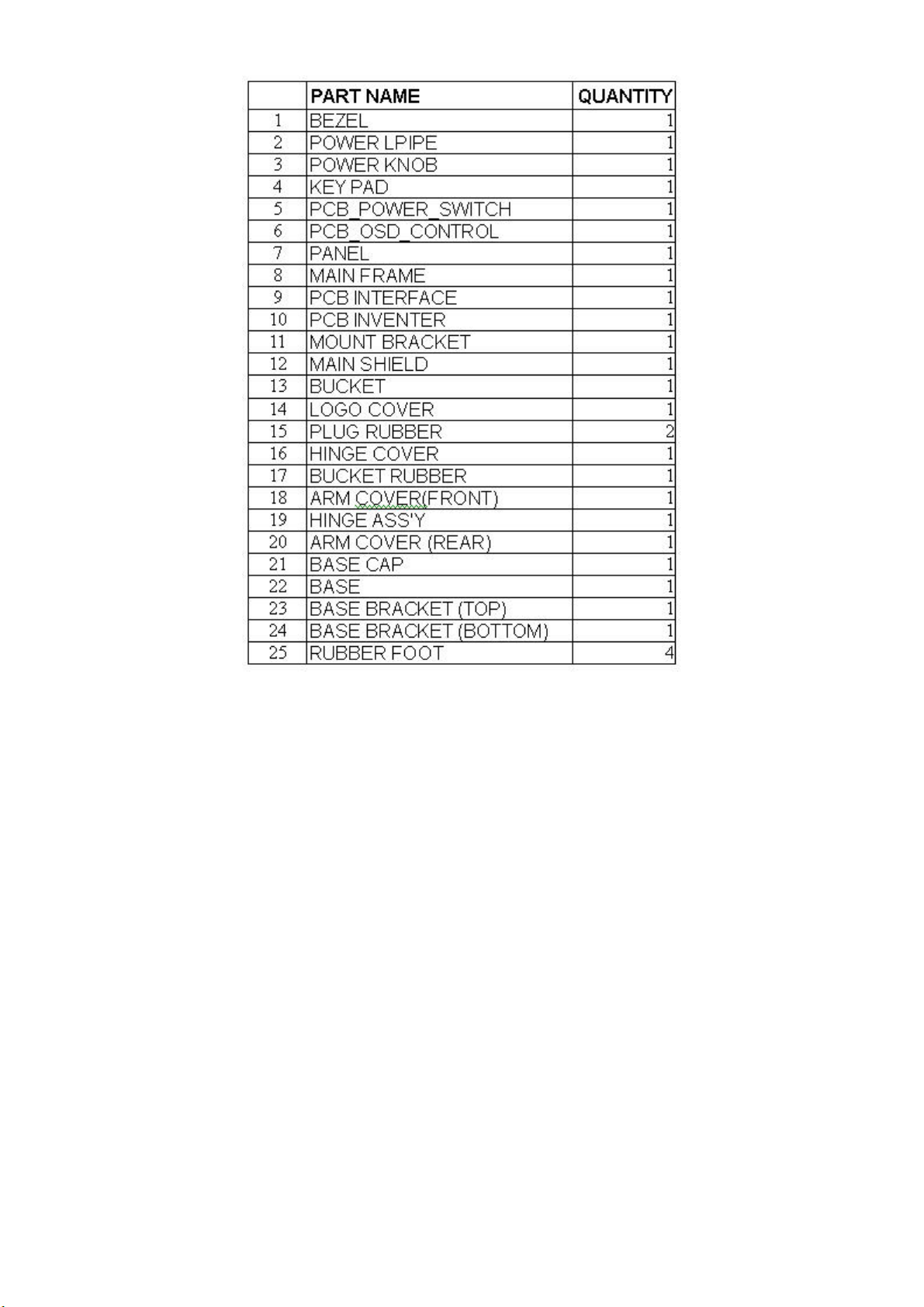
9. Part List
Level Location Number Specifacation Item Quantity Uni
*** T780KSKHKHHPA ***
----------------------------------------------------------------------------------------1 ADPC12416BH LCD ADAPTER ASS'Y 92 1.00000 PCS
1 CBPC780KSKHP CONVERSION BOARD 45 1.00000 PCS
1 IDPC7425A4 INVERTER BOARD 55 1.00000 PCS
1 KEPC560KC4 KEY
1 KEPC780KC2 KEY BOARD FOR T780K*HP 90 1.00000 PCS
1 2L6008 1 SCREW 78 2.00000 PCS
1 12L 401 1 CM WASHER 56 2.00000 PCS
1 15L5826 1 MAIN FRAME SAMSUNG 4 1.00000 PCS
1 15L5828 1 MOUNT BRACKET 5 1.00000 PCS
1 23L3178690 3A LOGO 85 1.00000 PCS
1 34L1097 CM B HINGE COVER 63 1.00000 PCS
1 40L 152509 RECYCLE LABEL 66 0.00000 PCS
1 40L 152512 RECYCLE LABEL 67 0.00000 PCS
1 40L 190690 1 ID LABEL 57 1.00000 PCS
1 40L 581 26704 LABEL 50 0.10000 PCS
1 41L 68508 A CARDCARD 62 0.20000 PCS
1 44L3231 12 A EVA WASHER 80 2.00000 PCS
1 44L3522 3 CARTON 91 1.00000 PCS
1 44L3709 1 EPS (L) 19 1.00000 PCS
1 44L3709 2 EPS (R) 20 1.00000 PCS
PARD 89 1.00000 PCS
1 44L3709 5 U TYPE SHEET 22 1.00000 PCS
1 44L3709624 1A CARTON 54 1.00000 PCS
1 45L 77 3 PE BAG 68 173.00000 CM
1 45L 77500 PRINTING RIBBON 51 19.00000 CM
1 45L 77501 PRINTING RIBBON 52 0.50000 CM
1 45L 88609 2 EPE COVER (17") 23 1.00000 PCS
1 45L 88621 2 PE BAG 150X865X0.15T 24 1.00000 PCS
1 45L 88626 CP PE BAG 75 1.00000
1 52L 1186 TAPE 49 8.00000 CM
1 52L 1208 A TAPE 86 3.00000 PCS
1 52L 1210 A ADHESIVE TYPE 25(W)X 87 1.00000 PCS
1 52L6020 2HP3 PROTECT FILM 84 1.00000 PCS
1 52L6022 1 SMALL TAPE 83 15.00000 CM
1 85L 631 1 MAIN SHIELD 25 1.00000 PCS
1 89L 171 35 DC POWER CORD 41 1.00000 PCS
1 89L 173L15 28 SIGNAL CABLE 74 1.00000 PCS
1 89L402L18N YH POWER CORD 79 1.00000 PCS
CS
39
Page 40

HP f1703 Service Manual
Level Location Number Specifacation Item Quantity Uni
-----------------------------------------------------------------------------1 95L8018 30 10 HARNESS 43 1.00000 PCS
1 M1L 330 4128 SCREW M3X4 27 2.00000 PCS
1 M1L 330 6128 SCREW (M3X6) 29 2.00000 PCS
1 M1L1730 6128 SCREW 82 12.00000 PCS
1 Q1L 330 8120 SCREW 3X8mm 71 16.00000 PCS
1 705L 78HPA SPEAKER 70 1.00000 PCS
1 705L780KB34048 LCD BACK ASS'Y 81 1.00000 PCS
1 750LLK70200 LCD PANEL HT17E12-200 BY HYU 48 1.00000 PCS
1 AM1L1740 14128 SCREW 88 2.00000 PCS
*** ADPC12416BH ***
----------------------------------------------------------------------------------------2 ADPC12400BAI LCD ADAPTER ASS'Y FOR AI 210 1.00000 PCS
2 ADPC12400BSMT LCD ADAPTER ASS'Y FOR SMT 209 1.00000 PCS
2 ADPC12416BH6 LCD ADAPTER A6 ASS'Y 252 1.00000 PCS
2 GND1 9L6002 1 PIN 176 1.00000 PCS
2 40L 45762412A CBPC LABEL 232 2.00000 PCS
2 IC903 56L 139 3 PC123FY2 BY SHARP 3 1.00000 PCS
2 R911 61L152M10457F MOFR 100KOHM +-5% 2W 133 1.00000 PCS
2 C901 63L 107334 5 0.33uF 250V BY TEAPO 146 0.00000 PCS
2 C901 63L107K334 U MPX 0.33UF,275VAC,+-10% 145 1.00000 PCS
2 C902 65L305M1022E3 1000PF +-20% 400VAC BY TDK 240 1.00000 PCS
2 C903 65L305M1022E3 1000PF +-20% 400VAC BY TDK 241 1.00000 PCS
2 C902 65L305M1022EM 1000PF 20% 250V BY MURATA 163 0.00000 PCS
2 C903 65L305M1022EM 1000PF 20% 250V BY MURATA 164 0.00000 PCS
2 C916 65L306M3322F2 3300PF +-20% 250V AC 247 1.00000 PCS
2 C900 65L306M4722B2 4700pF +-20% 250VAC 248 1.00000 PCS
2 C921 67L 215102 3H 1000uf 16V 185 1.00000 PCS
2 C922 67L 215102 3H 1000uf 16V 205 1.00000 PCS
2 C921 67L 215102 3J 1000UF/16V 187 0.00000 PCS
2 C922 67L 215102 3J 1000UF/16V 231 0.00000 PCS
2 C921 67L 215102 3K 1000UF/16V 188 0.00000 PCS
2 C922 67L 215102 3K 1000UF/16V 230 0.00000 PCS
2 C906 67L 305220 7T 22uF +-20% 50V 216 1.00000 PCS
2 C904 67L305S10114H 100UF 400V 18*32mm 105 234 1.00000 PCS
2 71L 55 2 FERRITE BEAD A6 RH 5x6.2x1.6 K 217 1.00000 PCS
2 71L 55 30 FERRITE BEAD 4.3*2*3 100 1.00000 PCS
2 L901 73L 174 26 T1 LINE LILTER 0.45mm 238 1.00000 PCS
2 L902 73L 253 91 H CHOKE COIL 195 0.00000 PCS
40
Page 41

HP f1703 Service Manual
Y
A
Level Location Number Specifacation Item Quantity Uni
------------------------------------------------------------------------------
2 L902 73L 253 91 L CHOKE BY LI TA 78 0.00000 PCS
2 L902 73L 253 91 S CHOKE COIL 184 1.00000 PCS
2 T901 80L 600 3 L X'FMR BY LI TAI 41 0.00000 PCS
2 T901 80L 600 3 T X'FMR BY TDK 193 1.00000 PCS
2 LED1 81L 2 3 2P LED 246 1.00000 PCS
2 F901 84L 53 1 FUSE 2A 250V 230002 BY LIT 220 1.00000 PCS
2 CN901 87L 501 10 AC INLET RIGHT ANGLE 225 1.00000 PCS
2 89L 171509 POWER DC CABLE 250 1.00000 PCS
2 BD901 93L 50460 8 BRIDGE 2KBP06M 2A 400V B
PAN 89 1.00000 PCS
2 D901 93L 6026T52T FR107 BY TS 194 1.00000 PCS
2 D901 93L 6026W52T FR107 BY WILLAS 79 0.00000 PCS
2 D902 93L 6038P52T PS102R PAN JIT 134 1.00000 PCS
2 D902 93L 6038T52T FR103 TAIWAN SEMI 135 0.00000 PCS
2 705L 560 57 03 Q901 ASS'Y 112 1.00000 PCS
2 705L 560 61 03 R930 ASS'Y 198 1.00000 PCS
2 705L 560 61 04 NR901 ASS'Y 249 1.00000 PCS
2 705L 780 93 04 D911 ASS'Y FOR LCD 228 1.00000 PCS
2 715L 901 1 4 AC-
DAPTOR SHUTTLE BRD 54.0X1 159 1.00000 PCS
*** CBPC780KSKHP ***
----------------------------------------------------------------------------------------2 AIC780KSKHP MAIN BOARD 9 1.00000 PCS
2 CN5 33L3802 9H WAFER 9P RIGHT ANELE PITCH 1 1.00000 PCS
2 CN3 33L801724A H PIN HEADER 24P 2.0mm 3 1.00000 PCS
2 CN6 33L8022 14 H PIN HEADER FEMALE 2*7 90 4 1.00000 PCS
2 40L 457624 1A CPU LABEL 10 1.00000 PCS
2 40L 45762412A CBPC LABEL 14 1.00000 PCS
2 U8 56L1125137 S4H W78E65P-40 BY WINBOND 15 1.00000 PCS
2 CN1 88L 35315F HA DB15 RIGHT ANGLE FEMALE 6 1.00000 PCS
2 Y2 93L 22 55 H 20MHZ 16 1.00000 PCS
2 Y1 93L 22 64 CRYSTAL 27 MHZ 49US 8 1.00000 PCS
*** IDPC7425A4 ***
----------------------------------------------------------------------------------------2 IDPC7425A4SMT LCD INVERTER DC TO DC FOR SMT 1 1.00000 PCS
2 CON102 33L800914K H 2*7PIN DUAL ROW RIGHT ANGLE 22 1.00000 PCS
2 40L 45762412A CBPC LABEL 39 1.00000 PCS
2 FILM 52L6025 7500 MICA 49 1.00000 PCS
2 R128 61L 208109 64 1ohm +-5% 1W 52 1.00000 PCS
2 C213 64L179J1841AT MKT CAP. 0.18UF 100V RSB 12 1.00000 PCS
41
Page 42

HP f1703 Service Manual
A
P
N
Level Location Number Specifacation Item Quantity Uni
------------------------------------------------------------------------------
2 C214 64L179J1841AT MKT CAP. 0.18UF 100V RSB 13 1.00000 PCS
2 C215 65L 3J2206EM 22PF 5% SL 3KV MURATA 15 0.00000 PCS
2 C216 65L 3J2206EM 22PF 5% SL 3KV MURATA 17 0.00000 PCS
2 C217 65L 3J2206EM 22PF 5% SL 3KV MURATA 19 0.00000 PCS
2 C218 65L 3J2206EM 22PF 5% SL 3KV MURATA 21 0.00000 PCS
2 C215 65L 3J2206ET 22PF 5% SL 3KV 14 1.00000 PCS
2 C216 65L 3J2206ET 22PF 5% SL 3KV 16 1.00000 PCS
2 C217 65L 3J2206ET 22PF 5% SL 3KV 18 1.00000 PCS
2 C218 65L 3J2206ET 22PF 5% SL 3KV 20 1.00000 PCS
2 C102 67L215B221 4H 220uF 25V LTR221M1EF11VR HER M 3 1.00000 PCS
2 C101 67L215B471 3H 470uF 16V LTR471M1CF11VR 8*11m 50 1.00000 PCS
2 C112 67L215B471 3H 470uF 16V LTR471M1CF11VR 8*11m 5 1.00000 PCS
2 C113 67L215B471 3H 470uF 16V LTR471M1CF11VR 8*11m 6 1.00000 PCS
2 C116 67L215B471 3H 470uF 16V LTR471M1CF11VR 8*11m 7 1.00000 PCS
2 C117 67L215B471 3H 470uF 16V LTR471M1CF11VR 8*11m 8 1.00000 PCS
2 C201 67L215C151 4H 150uF 25V LZR151M1 HER ME 10 1.00000 PCS
2 C223 67L215C151 4H 150uF 25V LZR151M1 HER ME 40 1.00000 PCS
2 L106 71L 55 19 3.5 X 8.9 X 0.65 YENG TAT E6H 44 1.00000 PCS
2 L101 71L 55 28 FERRITE BEAD 7.62*5.08*6.40 23 1.00000 PCS
2 L203 73L 174 30 LS FILTER 48 0.00000 PCS
2 L204 73L 174 30 LS FILTER 46 0.00000 PCS
2 L203 73L 174 30 YS LINE FILITER 45 1.00000 PCS
2 L204 73L 174 30 YS LINE FILITER 47 1.00000 PCS
2 L102 73L 253138 L CHOKE BY LI TAI 25 0.00000 PCS
2 L103 73L 253138 L CHOKE BY LI T
I 27 0.00000 PCS
2 L201 73L 253138 L CHOKE BY LI TAI 29 0.00000 PCS
2 L202 73L 253138 L CHOKE BY LI TAI 31 0.00000 PCS
2 L102 73L 253138 Y CHOKE 24 1.00000 PCS
2 L103 73L 253138 Y CHOKE 26 1.00000 PCS
2 L201 73L 253138 Y CHOKE 28 1.00000 PCS
2 L202 73L 253138 Y CHOKE 30 1.00000 PCS
2 CON103 88L 304 7K DC POWER JACK 35 1.00000
CS
2 CON101 88L 304 8K DC JACK 2.0mm BY KORTAK 41 1.00000 PCS
*** KEPC560KC4 ***
----------------------------------------------------------------------------------------2 KEPC560KC4SMT KEY BOARD FOR T560/780K*HP 1 1.00000 PCS
2 CN102 33L3802 5H WAFER 5P RIGHT A
ELE PITCH 4 1.00000 PCS
2 SW105 77L 600 1GHJ TACT SWITCH 3 1.00000 PCS
2 CN103 95L8014 9 35 HARNESS 2 1.00000 PCS
42
Page 43

HP f1703 Service Manual
P
P
Level Location Number Specifacation Item Quantity Uni
------------------------------------------------------------------------------
*** KEPC780KC2 ***
----------------------------------------------------------------------------------------2 SW101 77L 600 1GHJ TACT SWITCH 5 1.00000 PCS
2 SW102 77L 600 1GHJ TACT SWITCH 6 1.00000 PCS
2 SW103 77L 600 1GHJ TACT SWITCH 7 1.00000 PCS
2 SW104 77L 600 1GHJ TACT SWITCH 3 1.00000 PCS
2 CN101 95L8014 5503 HARNESS 2 1.00000 PCS
2 715L1009 1 B KEPC 1 1.00000
CS
*** 705L780KB34048 ***
2 12L 402 1 RUBBER FOOT 3 4.00000 PCS
2 12L 403 1 CM WASHER 17 1.00000 PCS
2 15L5829 1 BASE BRACKET (TOP) 4 1.00000 PCS
2 15L5830 1 BASE BRACKET (BOTTOM) 5 1.00000 PCS
2 33L4567 CM L KEY PAD 6 1.00000 PCS
2 33L4568 1 L POWER BUTTON 19 1.00000 PCS
2 33L4569ACN C POWER LPIPE 8 1.00000 PCS
2 33L4570 CN L BASE CA
9 1.00000 PCS
2 33L4571 CM L LOGO COVER 16 1.00000 PCS
2 34L1094 CN B ARM COVER(TOP) 10 1.00000 PCS
2 34L1095 CN B ARM COVER(BOTTOM) 11 1.00000 PCS
2 34L1096 CN B BASE 12 1.00000 PCS
2 34L1098ACN B BEZEL 13 1.00000 PCS
2 34L1099ACM B REAR COVER 18 1.00000 PCS
2 37L 467 1 HINGE ASS'Y 14 1.00000 PCS
2 M1L 140 16120 SCREW M4X16 15 4.00000 PCS
2 M1L 330 6128 SCREW (M3X6) 2 2.00000 PCS
2 Q1L 130 8120 SCREW (3X8mm) 1 7.00000 PCS
*** ADPC12400BAI ***
----------------------------------------------------------------------------------------3 IC902 56L 158 2 T TL431 24 0.00000 PCS
3 IC905 56L 158 2 T TL431 27 0.00000 PCS
3 IC902 56L 158 4 T H431BA HI-SIN 25 1.00000 PCS
3 IC905 56L 158 4 T H431BA HI-SIN 26 1.00000 PCS
3 J907 61L 60220252T 2K OHM 5% 1/6W 7 1.00000 PCS
3 C905 65L 1K152 1T6052 1.5NF/1KV Z5F+-10% 22 1.00000 PCS
3 C905 65L 1K152 1T6285 1.5NF/1KV Z5F+-10% 35 0.00000 PCS
3 C905 65L 1K152 1T6921 1.5NF/1KV Z5F+-10% 36 0.00000 PCS
43
Page 44

HP f1703 Service Manual
P
P
Level Location Number Specifacation Item Quantity Uni
------------------------------------------------------------------------------
3 C920 65L517K681 2T6052 680PF 500V +-10% 25P 37 0.00000 PCS
3 C920 65L517K681 2T6213 680PF 500V +-10% 25P 19 1.00000 PCS
3 C920 65L517K681 2T6285 680PF 500V +-10% 25P 38 0.00000 PCS
3 C908 67L 305100 7T 10uF +-20% 50V 34 1.00000 PCS
3 C915 67L 305220 7T 22uF +-20% 50V 33 1.00000 PCS
3 C923 67L 305471 3T 470uF +-20% 16V 20 1.00000 PCS
3 FB901 71L 55 19 T BEAD 23 1.00000
CS
3 J901 95L 90 23 TIN COATED 5 0.00000 PCS
3 J902 95L 90 23 TIN COATED 1 0.00000 PCS
3 J903 95L 90 23 TIN COATED 2 0.00000 PCS
3 J904 95L 90 23 TIN COATED 3 0.00000 PCS
3 J905 95L 90 23 TIN COATED 4 0.00000 PCS
3 J906 95L 90 23 TIN COATED 6 0.00000 PCS
3 J908 95L 90 23 TIN COATED 9 0.00000 PCS
3 715L 901 1 5 ADAPTOR 32 1.00000 PCS
*** ADPC12400BSMT ***
----------------------------------------------------------------------------------------3 IC901 56L 379 27 FA13843N BY FUJI 77 1.00000 PCS
3 Q903 57L 417 4 CHIP PMBS3904 BY PHILIPS 35 1.00000 PCS
3 Q902 57L 417 6 PMBS3906/PHILIPS-SMT 36 1.00000 PCS
3 R928 61L0603102 CHIPR 1K OHM +-5% 1/16W 12 1.00000 PCS
3 R937 61L0603243 1F CHIP 2.43K 1/16W 1% 4 1.00000 PCS
3 R936 61L0603931 1F CHIP 9.31K OHM 1/16W 1% 5 1.00000 PCS
3 R925 61L0805000 CHIP 0 OHM 5% 1/10W 74 1.00000 PCS
3 R915 61L0805101 CHIP 100 OHM 1/10W 89 1.00000 PCS
3 R935 61L0805102 CHIP 1K OHM 1/10W 6 1.00000 PCS
3 R927 61L0805103 CHIP 10K OHM 1/10W 13 1.00000 PCS
3 R913 61L0805104 CHIP 100K OHM 1/10W 55 1.00000 PCS
3 R939 61L0805104 CHIP 100K OHM 1/10W 75 1.00000 PCS
3 R900 61L0805112 1.1K OHM 1/10W 59 1.00000 PCS
3 R922 61L0805114 CHIP RES 110K 1/10W 83 1.00000
CS
3 R918 61L0805133 CHIP 13K OHM 1/10W 90 1.00000 PCS
3 R919 61L0805203 CHIP 20K OHM 1/10W 72 1.00000 PCS
3 R914 61L0805204 200K OHM 1/10W 65 1.00000 PCS
3 R921 61L0805303 CHIP 30K OHM 1/10W 92 1.00000 PCS
3 R924 61L0805472 CHIP 4.7K OHM 1/10W 87 1.00000 PCS
3 R917 61L0805473 CHIP 47K OHM 1/10W 70 1.00000 PCS
3 R920 61L0805473 CHIP 47K OHM 1/10W 86 1.00000 PCS
3 R929 61L0805821 CHIP 820 OHM 1/10W 67 1.00000 PCS
44
Page 45

HP f1703 Service Manual
H
Level Location Number Specifacation Item Quantity Uni
------------------------------------------------------------------------------
3 R912 61L1206100 CHIP 10 OHM 1/8W 85 1.00000 PCS
3 R923 61L1206100 CHIP 10 OHM 1/8W 16 1.00000 PCS
3 R931 61L1206100 CHIP 10 OHM 1/8W 10 1.00000 PCS
3 R932 61L1206100 CHIP 10 OHM 1/8W 9 1.00000 PCS
3 R926 61L1206101 CHIP 100 OHM 5% 1/8W 14 1.00000 PCS
3 R905 61L1206304 CHIP 300K OHM 1/8W 30 1.00000 PCS
3 R906 61L1206304 CHIP 300K OHM 1/8W 29 1.00000 PCS
3 R907 61L1206304 CHIP 300K OHM 1/8W 28 1.00000 PCS
3 R908 61L1206304 CHIP 300K OHM 1/8W 27 1.00000 PCS
3 R909 61L1206304 CHIP 300K OHM 1/8W 26 1.00000 PCS
3 R910 61L1206304 CHIP 300K OHM 1/8W 25 1.00000 PCS
3 R934 61L1206471 CHIP 470 OHM 1/8W 7 1.00000 PCS
3 R933 61L1206472 CHIP 4.7K OHM 5% 1/8W 88 1.00000 PCS
3 R903 61L1206514 CHIP 510K OHM +-5% 1/8W 82 1.00000 PCS
3 R904 61L1206514 CHIP 510K OHM +-5% 1/8W 84 1.00000 PCS
3 R901 61L1206684 CHIP 680K OHM 1/8W 34 1.00000 PCS
3 R902 61L1206684 CHIP 680K OHM 1/8W 33 1.00000 PCS
3 C914 65L0603102 32 CHIP 1000PF 50V X7R 46 1.00000 PCS
3 C911 65L0603152 32 CHIP 1500PF 50V X7R 49 1.00000 PCS
3 C913 65L0603331 31 CHIP 330PF 50V NPO 62 1.00000 PCS
3 R938 65L0805102 32 CHIP CAP 1000PF 50V X7R 98 1.00000 PCS
3 C909 65L0805104 22 CHIP 0.1uF 25V X7R 0805 60 1.00000 PCS
3 C928 65L0805104 22 CHIP 0.1uF 25V X7R 0805 41 1.00000 PCS
3 C929 65L0805104 22 CHIP 0.1uF 25V X7R 0805 40 1.00000 PCS
3 C924 65L0805104 27 C
IP 0.1UF 25V Y5V 79 1.00000 PCS
3 C912 65L0805105 12 CHIP CAPACITOR0805 1UF 16V X7R 97 1.00000 PCS
3 C917 65L0805221 31 CHIP 220PF 50V NPO 64 1.00000 PCS
3 C930 65L0805334 27 0.33UF 1/5V 80 1.00000 PCS
3 C926 65L0805474 27 CHIP 0.47UF 25V Y5V 43 1.00000 PCS
3 C910 65L1206102 31 CHIP 1000PF 50V NPO 96 1.00000 PCS
3 D904 93L 64 32 LL4148 SMD 39 0.00000 PCS
3 D905 93L 64 32 LL4148 SMD 38 0.00000 PCS
3 D906 93L 64 32 LL4148 SMD 76 0.00000 PCS
3 D904 93L 6432V LL4148-GS08-SMT 53 1.00000 PCS
3 D905 93L 6432V LL4148-GS08-SMT 54 1.00000 PCS
3 D906 93L 6432V LL4148-GS08-SMT 81 1.00000 PCS
3 ZD901 93L 39S 15 T RLZ15B BY ROHM 95 1.00000 PCS
*** ADPC12416BH6 ***
----------------------------------------------------------------------------------------3 33L6007 1 LENS 1 1.00000 PCS
45
Page 46

HP f1703 Service Manual
P
M
Level Location Number Specifacation Item Quantity Uni
------------------------------------------------------------------------------
3 40L 154501 1 LABELHI-POT GROUNDING LABEL 6 1.00000 PCS
3 40L416B690 1A ADAPTER ID LABEL 7 1.00000 PCS
3 45L 88525 E PE BAG 3 1.00000 PCS
3 W33L4477 B T TOP COVER 4 1.00000 PCS
3 W33L4478 B T BOTTOM COVER 5 1.00000 PCS
*** AIC780KSKHP ***
-----------------------------------------------------------------------------------------
3 U5 56L 561 7 NT7181F 10 1.00000 PCS
3 U6 56L 561 7 NT7181F 11 1.00000
CS
3 U1 56L 562 21 ADE3000SX BY ST 12 1.00000 PCS
3 U7 56L 566 12 SI9933ADY-T1 13 1.00000 PCS
3 U3 56L 74F 14 P N74F14D 245 1.00000 PCS
3 U9 56L1133 33 M24C16-
N6T 16 1.00000 PCS
3 U2 56L1133 34 M24C02-WMN6T 17 1.00000 PCS
3 Q3 57L 417 4 CHIP PMBS3904 BY PHILIPS 18 1.00000 PCS
3 Q5 57L 417 4 CHIP PMBS3904 BY PHILIPS 19 1.00000 PCS
3 Q8 57L 417 4 CHIP PMBS3904 BY PHILIPS 20 1.00000 PCS
3 Q6 57L 417 6 PMBS3906/PHILIPS-SMT 21 1.00000 PCS
3 Q7 57L 417 6 PMBS3906/PHILIPS-SMT 22 1.00000 PCS
3 RP13 61L 125472 8 CHIP AR 8P4R 4.7K OHM+-5%1/16W 273 1.00000 PCS
3 FB18 71L 59C800 CHIP 0 OHM 1/16W 311 1.00000 PCS
3 FB19 71L 59C800 CHIP 0 OHM 1/16W 312 1.00000 PCS
3 FB20 71L 59C800 CHIP 0 OHM 1/16W 313 1.00000 PCS
3 R10 61L0603000 CHIP 0 OHM 1/16W 35 1.00000 PCS
3 R11 61L0603000 CHIP 0 OHM 1/16W 36 1.00000 PCS
3 R132 61L0603000 CHIP 0 OHM 1/16W 46 1.00000 PCS
3 R138 61L0603000 CHIP 0 OHM 1/16W 47 1.00000 PCS
3 R139 61L0603000 CHIP 0 OHM 1/16W 48 1.00000 PCS
3 R140 61L0603000 CHIP 0 OHM 1/16W 49 1.00000 PCS
3 R141 61L0603000 CHIP 0 OHM 1/16W 50 1.00000 PCS
3 R146 61L0603000 CHIP 0 OHM 1/16W 51 1.00000 PCS
3 R148 61L0603000 CHIP 0 OHM 1/16W 52 1.00000 PCS
3 R151 61L0603330 CHIP 0 OHM 1/16W 284 1.00000 PCS
3 R153 61L0603000 CHIP 0 OHM 1/16W 286 1.00000 PCS
3 R167 61L0603000 CHIP 0 OHM 1/16W 285 1.00000 PCS
3 R46 61L0603000 CHIP 0 OHM 1/16W 42 1.00000 PCS
3 R47 61L0603000 CHIP 0 OHM 1/16W 43 1.00000 PCS
3 R48 61L0603000 CHIP 0 OHM 1/16W 44 1.00000 PCS
46
Page 47

HP f1703 Service Manual
P
Level Location Number Specifacation Item Quantity Uni
------------------------------------------------------------------------------
3 R49 61L0603000 CHIP 0 OHM 1/16W 45 1.00000 PCS
3 R90 61L0603000 CHIP 0 OHM 1/16W 287 1.00000 PCS
3 R135 61L0603102 CHIPR 1K OHM +-5% 1/16W 58 1.00000 PCS
3 R136 61L0603102 CHIPR 1K OHM +-5% 1/16W 59 1.00000 PCS
3 R83 61L0603102 CHIPR 1K OHM +-5% 1/16W 53 1.00000 PCS
3 R88 61L0603102 CHIPR 1K OHM +-5% 1/16W 54 1.00000
CS
3 R91 61L0603102 CHIPR 1K OHM +-5% 1/16W 56 1.00000 PCS
3 R101 61L0603103 CHIPR 10K OHM +-5% 1/16W 69 1.00000 PCS
3 R134 61L0603103 CHIPR 10K OHM +-5% 1/16W 71 1.00000 PCS
3 R16 61L0603103 CHIPR 10K OHM +-5% 1/16W 60 1.00000 PCS
3 R162 61L0603103 CHIPR 10K OHM +-5% 1/16W 305 1.00000 PCS
3 R163 61L0603103 CHIPR 10K OHM +-5% 1/16W 299 1.00000 PCS
3 R164 61L0603103 CHIPR 10K OHM +-5% 1/16W 298 1.00000 PCS
3 R165 61L0603103 CHIPR 10K OHM +-5% 1/16W 294 1.00000 PCS
3 R166 61L0603103 CHIPR 10K OHM +-5% 1/16W 293 1.00000 PCS
3 R28 61L0603103 CHIPR 10K OHM +-5% 1/16W 61 1.00000 PCS
3 R29 61L0603103 CHIPR 10K OHM +-5% 1/16W 62 1.00000 PCS
3 R50 61L0603103 CHIPR 10K OHM +-5% 1/16W 63 1.00000 PCS
3 R56 61L0603103 CHIPR 10K OHM +-5% 1/16W 64 1.00000 PCS
3 R63 61L0603103 CHIPR 10K OHM +-5% 1/16W 65 1.00000 PCS
3 R65 61L0603103 CHIPR 10K OHM +-5% 1/16W 66 1.00000 PCS
3 R82 61L0603103 CHIPR 10K OHM +-5% 1/16W 67 1.00000 PCS
3 R99 61L0603103 CHIPR 10K OHM +-5% 1/16W 68 1.00000 PCS
3 R172 61L0603150 0F CHIP 150 OHM 1/16W 281 1.00000 PCS
3 R173 61L0603150 0F CHIP 150 OHM 1/16W 282 1.00000 PCS
3 R174 61L0603150 0F CHIP 150 OHM 1/16W 283 1.00000 PCS
3 R19 61L0603000 CHIP 150 OHM 1/16W 295 1.00000 PCS
3 R22 61L0603000 CHIP 150 OHM 1/16W 296 1.00000 PCS
3 R24 61L0603000 CHIP 150 OHM 1/16W 297 1.00000 PCS
3 R25 61L0603150 0F CHIP 150 OHM 1/16W 278 1.00000 PCS
3 R26 61L0603150 0F CHIP 150 OHM 1/16W 279 1.00000 PCS
3 R27 61L0603150 0F CHIP 150 OHM 1/16W 280 1.00000 PCS
3 R1 61L0603150 2F CHIP 15K OHM 1/16W 1% 72 1.00000 PCS
3 R3 61L0603150 2F CHIP 15K OHM 1/16W 1% 73 1.00000 PCS
3 R5 61L0603150 2F CHIP 15K OHM 1/16W 1% 74 1.00000 PCS
3 R66 61L0603204 CHIP 200K OHM 5% 1/16W 78 1.00000 PCS
3 R100 61L0603272 CHIP 2.7K OHM 1/16W 79 1.00000 PCS
3 R102 61L0603272 CHIP 2.7K OHM 1/16W 80 1.00000 PCS
3 R30 61L0603330 CHIP 33 OHM 1/16W 300 1.00000 PCS
3 R31 61L0603330 CHIP 33 OHM 1/16W 301 1.00000 PCS
47
Page 48

HP f1703 Service Manual
Level Location Number Specifacation Item Quantity Uni
------------------------------------------------------------------------------
3 R131 61L0603332 CHIP 3.3K OHM 1/16W 276 1.00000 PCS
3 R14 61L0603332 CHIP 3.3K OHM 1/16W 81 1.00000 PCS
3 R142 61L0603332 CHIP 3.3K OHM 1/16W 87 1.00000 PCS
3 R15 61L0603332 CHIP 3.3K OHM 1/16W 82 1.00000 PCS
3 R156 61L0603332 CHIP 3.3K OHM 1/16W 277 1.00000 PCS
3 R73 61L0603332 CHIP 3.3K OHM 1/16W 83 1.00000 PCS
3 R74 61L0603332 CHIP 3.3K OHM 1/16W 84 1.00000 PCS
3 R84 61L0603332 CHIP 3.3K OHM 1/16W 85 1.00000 PCS
3 R85 61L0603332 CHIP 3.3K OHM 1/16W 86 1.00000 PCS
3 R154 61L0603470 CHIPR 47 OHM +-5% 1/16W 306 1.00000 PCS
3 R155 61L0603470 CHIPR 47 OHM +-5% 1/16W 257 1.00000 PCS
3 R157 61L0603470 CHIPR 47 OHM +-5% 1/16W 258 1.00000 PCS
3 R158 61L0603470 CHIPR 47 OHM +-5% 1/16W 259 1.00000 PCS
3 R159 61L0603470 CHIPR 47 OHM +-5% 1/16W 263 1.00000 PCS
3 R160 61L0603470 CHIPR 47 OHM +-5% 1/16W 264 1.00000 PCS
3 R168 61L0603470 CHIPR 47 OHM +-5% 1/16W 304 1.00000 PCS
3 R169 61L0603470 CHIPR 47 OHM +-5% 1/16W 292 1.00000 PCS
3 R17 61L0603470 CHIPR 47 OHM +-5% 1/16W 291 1.00000 PCS
3 R170 61L0603470 CHIPR 47 OHM +-5% 1/16W 265 1.00000 PCS
3 R171 61L0603470 CHIPR 47 OHM +-5% 1/16W 272 1.00000 PCS
3 R20 61L0603470 CHIPR 47 OHM +-5% 1/16W 290 1.00000 PCS
3 R145 61L0603472 CHIPR 4.7K OHM +-5% 1/16W 92 1.00000 PCS
3 R161 61L0603472 CHIPR 4.7K OHM +-5% 1/16W 275 1.00000 PCS
3 R9 61L0603472 CHIPR 4.7K OHM +-5% 1/16W 91 1.00000 PCS
3 R87 61L0603473 CHIP 47K OHM 1/16W 93 1.00000 PCS
3 R98 61L0603511 CHIP 510 OHM 1/16W 94 1.00000 PCS
3 R18 61L0603121 CHIPR 75 OHM+-5% 1/16W 309 1.00000 PCS
3 R21 61L0603121 CHIPR 75 OHM+-5% 1/16W 314 1.00000 PCS
3 R23 61L0603121 CHIPR 75 OHM+-5% 1/16W 315 1.00000 PCS
3 R89 61L0805221 CHIP 220 OHM 1/10W 316 1.00000 PCS
3 R97 61L0805511 CHIP 510 OHM 1/10W 310 1.00000 PCS
3 C71 65L0603100 31 CHIP 10PF 50V NPO 98 1.00000 PCS
3 C14 65L0603101 32 100PF +-10% 50V X7R 99 1.00000 PCS
3 C59 65L0603101 32 100PF +-10% 50V X7R 100 1.00000 PCS
3 C62 65L0603101 32 100PF +-10% 50V X7R 101 1.00000 PCS
3 C65 65L0603101 32 100PF +-10% 50V X7R 102 1.00000 PCS
3 C16 65L0603102 32 CHIP 1000PF 50V X7R 103 1.00000 PCS
3 C174 65L0603102 32 CHIP 1000PF 50V X7R 106 1.00000 PCS
3 C57 65L0603102 32 CHIP 1000PF 50V X7R 104 1.00000 PCS
3 C68 65L0603102 32 CHIP 1000PF 50V X7R 105 1.00000 PCS
48
Page 49

HP f1703 Service Manual
X
F
Level Location Number Specifacation Item Quantity Uni
------------------------------------------------------------------------------
3 C104 65L0603103 32 0.01UF+-10% 50V X7R 112 1.00000 PCS
3 C106 65L0603103 32 0.01UF+-10% 50V X7R 113 1.00000 PCS
3 C13 65L0603103 32 0.01UF+-10% 50V X7R 107 1.00000 PCS
3 C17 65L0603103 32 0.01UF+-10% 50V X7R 108 1.00000 PCS
3 C19 65L0603103 32 0.01UF+-10% 50V X7R 109 1.00000 PCS
3 C96 65L0603103 32 0.01UF+-10% 50V X7R 110 1.00000 PCS
3 C98 65L0603103 32 0.01UF+-10% 50V X7R 111 1.00000 PCS
3 C102 65L0603104 12 CHIP 0.1UF 16V X7R 165 1.00000 PCS
3 C109 65L0603104 12 CHIP 0.1UF 16V X7R 166 1.00000 PCS
3 C11 65L0603104 12 CHIP 0.1UF 16V X7R 118 1.00000 PCS
3 C111 65L0603104 12 CHIP 0.1UF 16V
7R 167 1.00000 PCS
3 C115 65L0603104 12 CHIP 0.1UF 16V X7R 168 1.00000 PCS
3 C12 65L0603104 12 CHIP 0.1UF 16V X7R 119 1.00000 PCS
3 C121 65L0603104 12 CHIP 0.1UF 16V X7R 169 1.00000 PCS
3 C123 65L0603104 12 CHIP 0.1UF 16V X7R 170 1.00000 PCS
3 C129 65L0603104 12 CHIP 0.1UF 16V X7R 171 1.00000 PCS
3 C130 65L0603104 12 CHIP 0.1UF 16V X7R 172 1.00000 PCS
3 C135 65L0603104 12 CHIP 0.1UF 16V X7R 173 1.00000 PCS
3 C147 65L0603104 12 CHIP 0.1UF 16V X7R 174 1.00000 PCS
3 C15 65L0603104 12 CHIP 0.1UF 16V X7R 120 1.00000 PCS
3 C18 65L0603104 12 CHIP 0.1UF 16V X7R 121 1.00000 PCS
3 C23 65L0603104 12 CHIP 0.1UF 16V X7R 122 1.00000 PCS
3 C24 65L0603104 12 CHIP 0.1UF 16V X7R 123 1.00000 PCS
3 C25 65L0603104 12 CHIP 0.1UF 16V X7R 124 1.00000 PCS
3 C26 65L0603104 12 CHIP 0.1UF 16V X7R 125 1.00000 PCS
3 C27 65L0603104 12 CHIP 0.1UF 16V X7R 126 1.00000 PCS
3 C28 65L0603104 12 CHIP 0.1UF 16V X7R 127 1.00000 PCS
3 C29 65L0603104 12 CHIP 0.1UF 16V X7R 128 1.00000 PCS
3 C30 65L0603104 12 CHIP 0.1UF 16V X7R 129 1.00000 PCS
3 C31 65L0603104 12 CHIP 0.1UF 16V X7R 130 1.00000 PCS
3 C32 65L0603104 12 CHIP 0.1UF 16V X7R 131 1.00000 PCS
3 C33 65L0603104 12 CHIP 0.1UF 16V X7R 132 1.00000 PCS
3 C34 65L0603104 12 CHIP 0.1U
16V X7R 133 1.00000 PCS
3 C35 65L0603104 12 CHIP 0.1UF 16V X7R 134 1.00000 PCS
3 C36 65L0603104 12 CHIP 0.1UF 16V X7R 135 1.00000 PCS
3 C37 65L0603104 12 CHIP 0.1UF 16V X7R 136 1.00000 PCS
3 C4 65L0603104 12 CHIP 0.1UF 16V X7R 114 1.00000 PCS
3 C41 65L0603104 12 CHIP 0.1UF 16V X7R 137 1.00000 PCS
3 C42 65L0603104 12 CHIP 0.1UF 16V X7R 138 1.00000 PCS
3 C43 65L0603104 12 CHIP 0.1UF 16V X7R 139 1.00000 PCS
49
Page 50

HP f1703 Service Manual
V
Level Location Number Specifacation Item Quantity Uni
------------------------------------------------------------------------------
3 C44 65L0603104 12 CHIP 0.1UF 16V X7R 140 1.00000 PCS
3 C45 65L0603104 12 CHIP 0.1UF 16V X7R 141 1.00000 PCS
3 C46 65L0603104 12 CHIP 0.1UF 16V X7R 142 1.00000 PCS
3 C47 65L0603104 12 CHIP 0.1UF 16V X7R 143 1.00000 PCS
3 C48 65L0603104 12 CHIP 0.1UF 16V X7R 144 1.00000 PCS
3 C5 65L0603104 12 CHIP 0.1UF 16V X7R 115 1.00000 PCS
3 C50 65L0603104 12 CHIP 0.1UF 16V X7R 145 1.00000 PCS
3 C51 65L0603104 12 CHIP 0.1UF 16V X7R 146 1.00000 PCS
3 C52 65L0603104 12 CHIP 0.1UF 16V X7R 147 1.00000 PCS
3 C53 65L0603104 12 CHIP 0.1UF 16V X7R 148 1.00000 PCS
3 C54 65L0603104 12 CHIP 0.1UF 16V X7R 149 1.00000 PCS
3 C55 65L0603104 12 CHIP 0.1UF 16V X7R 150 1.00000 PCS
3 C56 65L0603104 12 CHIP 0.1UF 16V X7R 151 1.00000 PCS
3 C6 65L0603104 12 CHIP 0.1UF 16V X7R 116 1.00000 PCS
3 C60 65L0603104 12 CHIP 0.1UF 16V X7R 152 1.00000 PCS
3 C63 65L0603104 12 CHIP 0.1UF 16V X7R 153 1.00000 PCS
3 C66 65L0603104 12 CHIP 0.1UF 16V X7R 154 1.00000 PCS
3 C67 65L0603104 12 CHIP 0.1UF 16V X7R 155 1.00000 PCS
3 C7 65L0603104 12 CHIP 0.1UF 16V X7R 117 1.00000 PCS
3 C73 65L0603104 12 CHIP 0.1UF 16V X7R 156 1.00000 PCS
3 C74 65L0603104 12 CHIP 0.1UF 16V X7R 157 1.00000 PCS
3 C75 65L0603104 12 CHIP 0.1UF 16V X7R 158 1.00000 PCS
3 C76 65L0603104 12 CHIP 0.1UF 16V X7R 159 1.00000 PCS
3 C77 65L0603104 12 CHIP 0.1UF 16V X7R 160 1.00000 PCS
3 C86 65L0603104 12 CHIP 0.1UF 16V X7R 161 1.00000 PCS
3 C93 65L0603104 12 CHIP 0.1UF 16V X7R 162 1.00000 PCS
3 C94 65L0603104 12 CHIP 0.1UF 16V X7R 163 1.00000 PCS
3 C99 65L0603104 12 CHIP 0.1UF 16
X7R 164 1.00000 PCS
3 C182 65L0603105 17 1UF 16V Y5V 175 1.00000 PCS
3 C183 65L0603105 17 1UF 16V Y5V 176 1.00000 PCS
3 C184 65L0603105 17 1UF 16V Y5V 177 1.00000 PCS
3 C72 65L0603150 31 CHIP 15PF 50V NPO 178 1.00000 PCS
3 C189 65L0603270 31 CHIP 27P 50V NPO 308 1.00000 PCS
3 C83 65L0603270 31 CHIP 27P 50V NPO 302 1.00000 PCS
3 C113 65L0603330 31 33PF+-5% 50V NPO 179 1.00000 PCS
3 C114 65L0603330 31 33PF+-5% 50V NPO 180 1.00000 PCS
3 C185 65L0603470 32 CHIP 47PF 50V X7R 288 1.00000 PCS
3 C188 65L0603470 32 CHIP 47PF 50V X7R 289 1.00000 PCS
3 C58 65L0603474 17 CHIP 0.47UF 16V Y5V 181 1.00000 PCS
3 C61 65L0603474 17 CHIP 0.47UF 16V Y5V 182 1.00000 PCS
50
Page 51

HP f1703 Service Manual
E
Level Location Number Specifacation Item Quantity Uni
------------------------------------------------------------------------------
3 C64 65L0603474 17 CHIP 0.47UF 16V Y5V 183 1.00000 PCS
3 C20 65L1206106 05 CHIP 10UF 6.3V X5R 188 1.00000 PCS
3 C21 65L1206106 05 CHIP 10UF 6.3V X5R 189 1.00000 PCS
3 C22 65L1206106 05 CHIP 10UF 6.3V X5R 190 1.00000 PCS
3 C3 65L1206106 05 CHIP 10UF 6.3V X5R 187 1.00000 PCS
3 C40 65L1206106 05 CHIP 10UF 6.3V X5R 191 1.00000 PCS
3 C49 65L1206106 05 CHIP 10UF 6.3V X5R 192 1.00000 PCS
3 CP13 65L600M102 8T 1000PF+-20% 50V 8P X7R 193 1.00000 PCS
3 C1 67L 312220 3 SMD EC 22UF 16V 85C C SIZE 194 1.00000 PCS
3 C100 67L 312220 3 SMD EC 22UF 16V 85C C SIZE 201 1.00000 PCS
3 C101 67L 312220 3 SMD EC 22UF 16V 85C C SIZE 202 1.00000 PCS
3 C103 67L 312220 3 SMD EC 22UF 16V 85C C SIZE 203 1.00000 PCS
3 C105 67L 312220 3 SMD EC 22UF 16V 85C C SIZE 204 1.00000 PCS
3 C122 67L 312220 3 SMD EC 22UF 16V 85C C SIZE 205 1.00000 PCS
3 C125 67L 312220 3 SMD EC 22UF 16V 85C C SIZE 206 1.00000 PCS
3 C131 67L 312220 3 SMD EC 22UF 16V 85C C SIZE 207 1.00000 PCS
3 C178 67L 312220 3 SMD EC 22UF 16V 85C C SIZE 209 1.00000 PCS
3 C179 67L 312220 3 SMD EC 22UF 16V 85C C SIZE 210 1.00000 PCS
3 C180 67L 312220 3 SMD EC 22UF 16V 85C C SIZE 211 1.00000 PCS
3 C181 67L 312220 3 SMD EC 22UF 16V 85C C SIZE 212 1.00000 PCS
3 C2 67L 312220 3 SMD EC 22UF 16V 85C C SIZE 195 1.00000 PCS
3 C38 67L 312220 3 SMD EC 22UF 16V 85C C SIZE 196 1.00000 PCS
3 C39 67L 312220 3 SMD EC 22UF 16V 85C C SIZE 197 1.00000 PCS
3 C92 67L 312220 3 SMD EC 22UF 16V 85C C SIZE 198 1.00000 PCS
3 C95 67L 312220 3 SMD EC 22UF 16V 85C C SIZE 199 1.00000 PCS
3 C97 67L 312220 3 SMD EC 22UF 16V 85C C SIZE 200 1.00000 PCS
3 C173 67L 312229 7 SMD EC 2.2UF 50V 85C 274 1.00000 PCS
3 C176 67L 312479 6 SMD
C 4.7UF 35V 85C 255 1.00000 PCS
3 C177 67L 312479 6 SMD EC 4.7UF 35V 85C 254 1.00000 PCS
3 FB1 71L 56U600 CHIP BEAD 60 OHM 0805TB201209- 215 1.00000 PCS
3 FB10 71L 56U600 CHIP BEAD 60 OHM 0805TB201209- 222 1.00000 PCS
3 FB2 71L 56U600 CHIP BEAD 60 OHM 0805TB201209- 216 1.00000 PCS
3 FB4 71L 56U600 CHIP BEAD 60 OHM 0805TB201209- 218 1.00000 PCS
3 FB6 71L 56U600 CHIP BEAD 60 OHM 0805TB201209- 219 1.00000 PCS
3 FB7 71L 56U600 CHIP BEAD 60 OHM 0805TB201209- 220 1.00000 PCS
3 FB9 71L 56U600 CHIP BEAD 60 OHM 0805TB201209- 221 1.00000 PCS
3 FB12 71L 59C121 B FCM1608C-121T03 246 1.00000 PCS
3 FB13 71L 59C121 B FCM1608C-121T03 247 1.00000 PCS
3 FB14 71L 59C121 B FCM1608C-121T03 248 1.00000 PCS
51
Page 52

HP f1703 Service Manual
Level Location Number Specifacation Item Quantity Uni
------------------------------------------------------------------------------
3 FB15 71L 59C121 B FCM1608C-121T03 249 1.00000 PCS
3 FB16 71L 59C121 B FCM1608C-121T03 250 1.00000 PCS
3 FB17 71L 59C121 B FCM1608C-121T03 251 1.00000 PCS
3 U8 87L 202 44 PLCC SMT CONN PD41C-4411 15 1.00000 PCS
3 ZD1 93L 39144 CHIP ZD 3.3V MLL522B BY FCI 230 1.00000 PCS
3 D1 93L 60230 BAT54C BY MCC 252 1.00000 PCS
3 D20 93L 6432V LL4148-GS08-SMT 319 1.00000 PCS
3 D2 93L 6433P BAV99 SOT-23 BY PAN JIT 260 1.00000 PCS
3 D3 93L 6433P BAV99 SOT-23 BY PAN JIT 261 1.00000 PCS
3 D4 93L 6433P BAV99 SOT-23 BY PAN JIT 262 1.00000 PCS
3 ZD2 93L 39S155 BZT52-C5V6 231 1.00000 PCS
3 ZD3 93L 39S155 BZT52-C5V6 232 1.00000 PCS
3 ZD4 93L 39S155 BZT52-C5V6 233 1.00000 PCS
3 ZD5 93L 39S155 BZT52-C5V6 234 1.00000 PCS
3 715L1006 1 17" HP MAIN BOARD PCB 322 1.00000 PCS
*** IDPC7425A4SMT ***
----------------------------------------------------------------------------------------3 CON201 33L8021 2 E WAFER 61 0.00000 PCS
3 CON202 33L8021 2 E WAFER 63 0.00000 PCS
3 CON203 33L8021 2 E WAFER 65 0.00000 PCS
3 CON204 33L8021 2 E WAFER 67 0.00000 PCS
3 CON201 33L8021 2 J WAFER 2P BHS BY JST 60 1.00000 PCS
3 CON202 33L8021 2 J WAFER 2P BHS BY JST 62 1.00000 PCS
3 CON203 33L8021 2 J WAFER 2P BHS BY JST 64 1.00000 PCS
3 CON204 33L8021 2 J WAFER 2P BHS BY JST 66 1.00000 PCS
3 U102 56L 563 9 AIC1084CM TO-263 ANALOG 198 1.00000 PCS
3 Q101 56L 566 10 SI4431DY-T1 SO8 SILICONE 104 0.00000 PCS
3 Q102 56L 566 10 SI4431DY-T1 SO8 SILICONE 106 0.00000 PCS
3 Q203 56L 566 10 SI4431DY-T1 SO8 SILICONE 116 0.00000 PCS
3 Q204 56L 566 10 SI4431DY-T1 SO8 SILICONE 118 0.00000 PCS
3 U201 56L 608 1 TL1451ACD BY TI 231 1.00000 PCS
3 U101 56L 622 1 BA9741F-SMT 232 1.00000 PCS
3 Q103 57L 417 4 CHIP PMBS3904 BY PHILIPS 107 1.00000 PCS
3 Q104 57L 417 4 CHIP PMBS3904 BY PHILIPS 108 1.00000 PCS
3 Q205 57L 417 4 CHIP PMBS3904 BY PHILIPS 119 1.00000 PCS
3 Q206 57L 417 4 CHIP PMBS3904 BY PHILIPS 120 1.00000 PCS
3 Q105 57L 417 6 PMBS3906/PHILIPS-SMT 218 1.00000 PCS
3 Q106 57L 417 6 PMBS3906/PHILIPS-SMT 216 1.00000 PCS
3 Q207 57L 417 6 PMBS3906/PHILIPS-SMT 215 1.00000 PCS
52
Page 53

HP f1703 Service Manual
Level Location Number Specifacation Item Quantity Uni
------------------------------------------------------------------------------
3 Q208 57L 417 6 PMBS3906/PHILIPS-SMT 214 1.00000 PCS
3 Q202 57L 760 1 FN1L4L BT NEC 114 0.00000 PCS
3 Q201 57L 760 2 FA1L4L BT NEC 112 0.00000 PCS
3 Q202 57L 760 4 DTA144WKA BY ROHM 113 1.00000 PCS
3 Q201 57L 760 5 DTC144WKA BY ROHM 111 1.00000 PCS
3 Q209 57L 761 2 2SC5706-TL BY SANYO 123 1.00000 PCS
3 Q210 57L 761 2 2SC5706-TL BY SANYO 125 1.00000 PCS
3 Q211 57L 761 2 2SC5706-TL BY SANYO 127 1.00000 PCS
3 Q212 57L 761 2 2SC5706-TL BY SANYO 129 1.00000 PCS
3 Q209 57L 761 3 2SC5824 BY ROHM 124 0.00000 PCS
3 Q210 57L 761 3 2SC5824 BY ROHM 126 0.00000 PCS
3 Q211 57L 761 3 2SC5824 BY ROHM 128 0.00000 PCS
3 Q212 57L 761 3 2SC5824 BY ROHM 130 0.00000 PCS
3 Q101 57L 763 3 AO4411 SO-8 BY AOS 103 1.00000 PCS
3 Q102 57L 763 3 AO4411 SO-8 BY AOS 105 1.00000 PCS
3 Q203 57L 763 3 AO4411 SO-8 BY AOS 115 1.00000 PCS
3 Q204 57L 763 3 AO4411 SO-8 BY AOS 117 1.00000 PCS
3 R109 61L0603100 CHIP 10 OHM 1/16W 138 1.00000 PCS
3 R101 61L0603103 CHIPR 10K OHM +-5% 1/16W 131 1.00000 PCS
3 R124 61L0603103 CHIPR 10K OHM +-5% 1/16W 153 1.00000 PCS
3 R204 61L0603103 CHIPR 10K OHM +-5% 1/16W 160 1.00000 PCS
3 R126 61L0603120 0F CHIP 120 OHM 1/16W 155 1.00000 PCS
3 R125 61L0603123 CHIP 12K OHM 1/16W 154 1.00000 PCS
3 R210 61L0603123 CHIP 12K OHM 1/16W 165 1.00000 PCS
3 R211 61L0603123 CHIP 12K OHM 1/16W 166 1.00000 PCS
3 R222 61L0603123 CHIP 12K OHM 1/16W 177 1.00000 PCS
3 R223 61L0603123 CHIP 12K OHM 1/16W 178 1.00000 PCS
3 R238 61L0603123 CHIP 12K OHM 1/16W 193 1.00000 PCS
3 R239 61L0603123 CHIP 12K OHM 1/16W 194 1.00000 PCS
3 R201 61L0603153 CHIP 15K OHM 1/16W 157 1.00000 PCS
3 R220 61L0603153 CHIP 15K OHM 1/16W 175 1.00000 PCS
3 R221 61L0603153 CHIP 15K OHM 1/16W 176 1.00000 PCS
3 R123 61L0603203 CHIPR 20K OHM+-5% 1/16W 152 1.00000 PCS
3 R112 61L0603221 CHIPR 220 OHM+-5% 1/16W 141 1.00000 PCS
3 R113 61L0603221 CHIPR 220 OHM+-5% 1/16W 142 1.00000 PCS
3 R216 61L0603221 CHIPR 220 OHM+-5% 1/16W 171 1.00000 PCS
3 R217 61L0603221 CHIPR 220 OHM+-5% 1/16W 172 1.00000 PCS
3 R120 61L0603243 CHIP 24K OHM 1/16W 149 1.00000 PCS
3 R121 61L0603243 CHIP 24K OHM 1/16W 150 1.00000 PCS
3 R122 61L0603333 CHIP 33K OHM 1/16W 211 1.00000 PCS
53
Page 54

HP f1703 Service Manual
M
P
Level Location Number Specifacation Item Quantity Uni
------------------------------------------------------------------------------
3 R105 61L0603392 CHIP 3.9K OHM 1/16W 134 1.00000 PCS
3 R106 61L0603392 CHIP 3.9K OHM 1/16W 135 1.00000 PCS
3 R110 61L0603392 CHIP 3.9K OHM 1/16W 139 1.00000 PCS
3 R111 61L0603392 CHIP 3.9K OHM 1/16W 140 1.00000 PCS
3 R114 61L0603392 CHIP 3.9K OHM 1/16W 143 1.00000 PCS
3 R115 61L0603392 CHIP 3.9K OHM 1/16W 144 1.00000 PCS
3 R118 61L0603392 CHIP 3.9K OHM 1/16W 147 1.00000 PCS
3 R119 61L0603392 CHIP 3.9K OH
1/16W 148 1.00000 PCS
3 R212 61L0603392 CHIP 3.9K OHM 1/16W 167 1.00000 PCS
3 R213 61L0603392 CHIP 3.9K OHM 1/16W 168 1.00000 PCS
3 R214 61L0603392 CHIP 3.9K OHM 1/16W 169 1.00000 PCS
3 R215 61L0603392 CHIP 3.9K OHM 1/16W 170 1.00000 PCS
3 R116 61L0603471 CHIP 470 OHM 1/16W 145 1.00000 PCS
3 R117 61L0603471 CHIP 470 OHM 1/16W 146 1.00000 PCS
3 R218 61L0603471 CHIP 470 OHM 1/16W 173 1.00000
CS
3 R219 61L0603471 CHIP 470 OHM 1/16W 174 1.00000 PCS
3 R208 61L0603472 CHIPR 4.7K OHM +-5% 1/16W 163 1.00000 PCS
3 R209 61L0603472 CHIPR 4.7K OHM +-5% 1/16W 164 1.00000 PCS
3 R103 61L0603473 CHIP 47K OHM 1/16W 132 1.00000 PCS
3 R104 61L0603473 CHIP 47K OHM 1/16W 133 1.00000 PCS
3 R107 61L0603473 CHIP 47K OHM 1/16W 136 1.00000 PCS
3 R108 61L0603473 CHIP 47K OHM 1/16W 137 1.00000 PCS
3 R205 61L0603473 CHIP 47K OHM 1/16W 161 1.00000 PCS
3 R206 61L0603473 CHIP 47K OHM 1/16W 162 1.00000 PCS
3 R202 61L0603512 CHIP 5.1K OHM 1/16W 158 1.00000 PCS
3 R203 61L0603512 CHIP 5.1K OHM 1/16W 159 1.00000 PCS
3 R240 61L0603513 CHIP 51K OHM 195 1.00000 PCS
3 R241 61L0603513 CHIP 51K OHM 196 1.00000 PCS
3 R236 61L0603561 CHIP 560 OHM 1/16W 191 1.00000 PCS
3 R237 61L0603561 CHIP 560 OHM 1/16W 192 1.00000 PCS
3 R127 61L0603604 9F CHIP 60.4 OHM 1/16W 1% 206 1.00000 PCS
3 R234 61L0603621 CHIP 620 OHM 1/16W 189 1.00000 PCS
3 R235 61L0603621 CHIP 620 OHM 1/16W 190 1.00000 PCS
3 R224 61L1206102 CHIP 1K OHM 5% 1/8W 179 1.00000 PCS
3 R225 61L1206102 CHIP 1K OHM 5% 1/8W 180 1.00000 PCS
3 R226 61L1206102 CHIP 1K OHM 5% 1/8W 181 1.00000 PCS
3 R227 61L1206102 CHIP 1K OHM 5% 1/8W 182 1.00000 PCS
3 R228 61L1206102 CHIP 1K OHM 5% 1/8W 183 1.00000 PCS
3 R229 61L1206102 CHIP 1K OHM 5% 1/8W 184 1.00000 PCS
3 R230 61L1206102 CHIP 1K OHM 5% 1/8W 185 1.00000 PCS
54
Page 55

HP f1703 Service Manual
Level Location Number Specifacation Item Quantity Uni
------------------------------------------------------------------------------
3 R231 61L1206102 CHIP 1K OHM 5% 1/8W 186 1.00000 PCS
3 R232 61L1206102 CHIP 1K OHM 5% 1/8W 187 1.00000 PCS
3 R233 61L1206102 CHIP 1K OHM 5% 1/8W 188 1.00000 PCS
3 C103 65L0805104 22 CHIP 0.1uF 25V X7R 0805 32 1.00000 PCS
3 C106 65L0805104 22 CHIP 0.1uF 25V X7R 0805 34 1.00000 PCS
3 C107 65L0805104 22 CHIP 0.1uF 25V X7R 0805 35 1.00000 PCS
3 C114 65L0805104 22 CHIP 0.1uF 25V X7R 0805 40 1.00000 PCS
3 C115 65L0805104 22 CHIP 0.1uF 25V X7R 0805 41 1.00000 PCS
3 C118 65L0805104 22 CHIP 0.1uF 25V X7R 0805 42 1.00000 PCS
3 C202 65L0805104 22 CHIP 0.1uF 25V X7R 0805 43 1.00000 PCS
3 C204 65L0805104 22 CHIP 0.1uF 25V X7R 0805 45 1.00000 PCS
3 C205 65L0805104 22 CHIP 0.1uF 25V X7R 0805 46 1.00000 PCS
3 C206 65L0805104 22 CHIP 0.1uF 25V X7R 0805 47 1.00000 PCS
3 C110 65L0805105 27 CHIP 1UF 25V Y5V 38 1.00000 PCS
3 C111 65L0805105 27 CHIP 1UF 25V Y5V 39 1.00000 PCS
3 C203 65L0805105 27 CHIP 1UF 25V Y5V 44 1.00000 PCS
3 C209 65L0805105 27 CHIP 1UF 25V Y5V 49 1.00000 PCS
3 C210 65L0805105 27 CHIP 1UF 25V Y5V 50 1.00000 PCS
3 C211 65L0805105 27 CHIP 1UF 25V Y5V 51 1.00000 PCS
3 C212 65L0805105 27 CHIP 1UF 25V Y5V 52 1.00000 PCS
3 C219 65L0805105 27 CHIP 1UF 25V Y5V 53 1.00000 PCS
3 C220 65L0805105 27 CHIP 1UF 25V Y5V 54 1.00000 PCS
3 C105 65L0805331 32 CHIP 330PF 50V X7R 0805 33 1.00000 PCS
3 C208 65L0805331 32 CHIP 330PF 50V X7R 0805 48 1.00000 PCS
3 C108 65L0805474 27 CHIP 0.47UF 25V Y5V 36 1.00000 PCS
3 C109 65L0805474 27 CHIP 0.47UF 25V Y5V 37 1.00000 PCS
3 C221 65L0805474 27 CHIP 0.47UF 25V Y5V 55 1.00000 PCS
3 C222 65L0805474 27 CHIP 0.47UF 25V Y5V 56 1.00000 PCS
3 C104 67L 312479 6 SMD EC 4.7UF 35V 85C 200 1.00000 PCS
3 C207 67L 312479 6 SMD EC 4.7UF 35V 85C 227 1.00000 PCS
3 L104 71L 57G601 TI3216JIG601-T17A 97 1.00000 PCS
3 L105 71L 57G601 TI3216JIG601-T17A 98 1.00000 PCS
3 L107 71L 57G601 TI3216JIG601-T17A 223 1.00000 PCS
3 L108 71L 57G601 TI3216JIG601-T17A 224 1.00000 PCS
3 PT201 80LL17T 3 YS ADAPTOR BY YAO SHENG SMT 101 1.00000 PCS
3 PT202 80LL17T 3 YS ADAPTOR BY YAO SHENG SMT 102 1.00000 PCS
3 F102 84L 52 1 CHIP FUSE 3216FF-2A COOPER 95 1.00000 PCS
3 F103 84L 52 3 CHIP FUSE 3216FF-3A 96 1.00000 PCS
3 F101 84L 52 5 CHIP FUSE 3216FF-6.5A 94 1.00000 PCS
3 D103 93L 39147 TZMC5V6-GS08 217 1.00000 PCS
55
Page 56

HP f1703 Service Manual
Level Location Number Specifacation Item Quantity Uni
------------------------------------------------------------------------------
3 D103 93L 39155 ZD BZT52-C5V6 5.2-6V PAN JI 219 0.00000 PCS
3 D207 93L 6432U MLL4148/FULLPOWER-SMT 91 0.00000 PCS
3 D208 93L 6432U MLL4148/FULLPOWER-SMT 93 0.00000 PCS
3 D207 93L 6432V LL4148-GS08-SMT 90 1.00000 PCS
3 D208 93L 6432V LL4148-GS08-SMT 92 1.00000 PCS
3 D205 93L 6433G BAV99 SOT-23 BY GI 87 0.00000 PCS
3 D206 93L 6433G BAV99 SOT-23 BY GI 89 0.00000 PCS
3 D205 93L 6433P BAV99 SOT-23 BY PAN JIT 86 1.00000 PCS
3 D206 93L 6433P BAV99 SOT-23 BY PAN JIT 88 1.00000 PCS
3 D203 93L 39S 1 T 11V CHIP ZEHER 82 0.00000 PCS
3 D204 93L 39S 1 T 11V CHIP ZEHER 85 0.00000 PCS
3 D203 93L 39S 3 T 11V 10.4-11.6V BY PAN 81 0.00000 PCS
3 D204 93L 39S 3 T 11V 10.4-11.6V BY PAN 84 0.00000 PCS
3 D104 93L 39S 4 T 3V BY PAN 74 1.00000 PCS
3 D104 93L 39S 7 T 3.0V MLL5225B BY FUL 75 0.00000 PCS
3 D203 93L 39S 8 T 11V RLZ11B BY ROHM 80 1.00000 PCS
3 D204 93L 39S 8 T 11V RLZ11B BY ROHM 83 1.00000 PCS
3 D101 93L2004 1 SMAL240LV FULL POWER 69 0.00000 PCS
3 D102 93L2004 1 SMAL240LV FULL POWER 71 0.00000 PCS
3 D201 93L2004 1 SMAL240LV FULL POWER 77 0.00000 PCS
3 D202 93L2004 1 SMAL240LV FULL POWER 79 0.00000 PCS
3 D101 93L2004 2 SR24 PAN JIT 68 1.00000 PCS
3 D102 93L2004 2 SR24 PAN JIT 70 1.00000 PCS
3 D201 93L2004 2 SR24 PAN JIT 76 1.00000 PCS
3 D202 93L2004 2 SR24 PAN JIT 78 1.00000 PCS
3 PCB 715L1003 1 S PCB 230 1.00000 PCS
*** KEPC560KC4SMT ***
----------------------------------------------------------------------------------------3 LED1 81L 14 3 HL CHIP LED B/Y MHB10-1411 BY HI- 1 1.00000 PCS
3 715L1009 1 A POWER KEY BRD PCB 4 1.00000 PCS
*** 705L 560 57 03 ***
----------------------------------------------------------------------------------------3 Q901 57L 724 4 2SK2996 BY TOSHIBA 8 1.00000 PCS
3 90L 396502 Q HEAT SINK 9 1.00000 PCS
3 M1L1730 7128 SCREW 6 1.00000 PCS
*** 705L 560 61 03 ***
-----------------------------------------------------------------------------------------
56
Page 57

HP f1703 Service Manual
Level Location Number Specifacation Item Quantity Uni
-----------------------------------------------------------------------------3 R930 61L 2J47859B WIRE WOUND 0.47 OHM ZW 2 1.00000 PCS
3 96L 29 6 M96INK TUBE UL/CSA 3 1.00000 PCS
*** 705L 560 61 04 ***
----------------------------------------------------------------------------------------3 NR901 61L 58080 WT NTC 8 OHM SCK083LG0282 2 1.00000 PCS
3 96L 29 10 SHRINR TUBE UL/CSA 1 1.00000 PCS
*** 705L 780 93 04 ***
----------------------------------------------------------------------------------------3 90L 396500 D HEAT SINK 17 1.00000 PCS
3 D911 93L 60226 STPS20H20100 20A 100V BT ST 16 0.00000 PCS
3 D911 93L 60227 MBR20100CT 20A 100V BT IR 13 1.00000 PCS
3 M1L1730 6128 SCREW 21 1.00000 PCS
57
 Loading...