

Page 1

HP Mannequin (f1503) Service Manual
SERVICE MANUAL
15” LCD Monitor
f1503
THESE DOCUMENTS ARE FOR REPAIR SERVICE INFORMATION ONLY. EVERY REASONABLE
EFFORT HAS BEEN MADE TO ENSURE THE ACCURACY OF THIS MANUAL; WE CANNOT
GUARANTEE THE ACCURACY OF THIS INFORMATION AFTER THE DATE OF PUBLICATION AND
DISCLAIMS RELIABILITY FOR CHANGES, ERRORS OR OMISSIONS.
1
P/N:
Page 2

HP Mannequin (f1503) Service Manual
I. Revision List
Revision Date Change Description
2
Page 3

HP Mannequin (f1503) Service Manual
II. Table of Contents
I. Revision List ............................................................................................................................. 2
II. Table of Contents .................................................................................................................... 3
1. MONITOR SPECIFICATIONS ............................................................................................ 5
2. LCD MONITOR DESCRIPTION ......................................................................................... 6
3. OPERATING INSTRUCTIONS ............................................................................................ 7
3.1 General Instructions ............................................................................................................................. 7
3.2 Control Buttons .................................................................................................................................... 7
3.3 Adjust The Picture ................................................................................................................................ 8
4. Input/Outpt Specification ....................................................................................................... 9
4.1 Input Signal Connector .......................................................................................................................... 9
4.1.1 Analog D-SUB Connector ............................................................................................................. 9
4.2 Factory Preset Display Modes ............................................................................................................. 10
4.3 Power Supply Requirements ................................................................................................................ 11
4.3.1 Input Requirements ..................................................................................................................... 11
4.3.2 Output Requirements ................................................................................................................... 11
4.4 PANEL SPECIFICATION (Hannstar ) .............................................................................................. 12
4.4.1 Panel Feature ............................................................................................................................... 12
4.4.2 Display Characteristics ................................................................................................................ 12
4.4.3 Optical Characteristics................................................................................................................. 12
4.4.4 Parameter guide line for CCFL Inverter ...................................................................................... 13
5. Block Diagram ....................................................................................................................... 14
5.1 Monitor Exploded View ....................................................................................................................... 14
5.1.1 f1503 ............................................................................................................................................ 14
5.1.2 f1503 ............................................................................................................................................ 15
5.2 Software Flow Chart ............................................................................................................................ 16
5.3 Electrical Block Diagram ..................................................................................................................... 17
5.3.1 Main Board .................................................................................................................................. 17
6. Schematic ................................................................................................................................ 18
6.1 Main Board ........................................................................................................................................... 18
6.2 Power Board .......................................................................................................................................... 23
6.3 Key Board ............................................................................................................................................. 24
3
Page 4

HP Mannequin (f1503) Service Manual
7. PCB Layout ............................................................................................................................ 25
7.1 Main Board ........................................................................................................................................... 25
7.2 Power Board .......................................................................................................................................... 26
7.3 Key Board ............................................................................................................................................. 27
8. Maintainability....................................................................................................................... 28
8.1 Equipments and Tools Requirement ................................................................................................... 28
8.2 Trouble Shooting ................................................................................................................................... 29
8.2.1 Main Board .................................................................................................................................. 29
8.2.2 Power Board ................................................................................................................................ 31
8.2.3 Key Board .................................................................................................................................... 32
8.3 Alignment Procedure ............................................................................................................................ 32
8.4 DDC Writing ......................................................................................................................................... 33
8.4.1 DDC Writing Procedure .............................................................................................................. 33
8.4.2 EDID Content .............................................................................................................................. 33
8.4.3 Serial Number Format ................................................................................................................. 34
9. Part Lists .............................................................................................................................. 335
4
Page 5

HP Mannequin (f1503) Service Manual
1. MONITOR SPECIFICATIONS
Driving system TFT Color LCD
LCD Panel Size 38.1cm(15.0")
Pixel pitch 0.297( H )x 0.297( V ) mm
Viewable angle 130˚ (H) 100˚ (V)
Response time (typ.) 35 ms
Video Analog
Input Sync. Type H/V TTL Separate and Composite Sync.
H-Frequency 30kHz – 60kHz
V-Frequency 56-75Hz
Display Colors 16.7 million Colors
Dot Clock 80MHz
Max. Resolution 1024 x 768
Plug & Play VESA DDC2BTM
Power Consumption ON Mode <22W
ON Mode (With Speaker) <34 W
Power Saving <2 W
Power Saving (With Speaker)
Switch Off <2 W
Switch Off (With Speaker)
Maximum Screen Size
Power Source
Environmental
Considerations
Operating Temp: 5°C to 35°C
<14 W
<14 W
Horizontal : 12.0”(304.128mm)
Vertical : 9.0”(228.096mm)
90~264VAC,47~63Hz
Non-Operating Temp.: -20°C to 60°C
Operating Humidity : 20% to 80%
Weight (N. W.)
Package with Speaker 6.7Kgs Unit (net)
5
Page 6
HP Mannequin (f1503) Service Manual
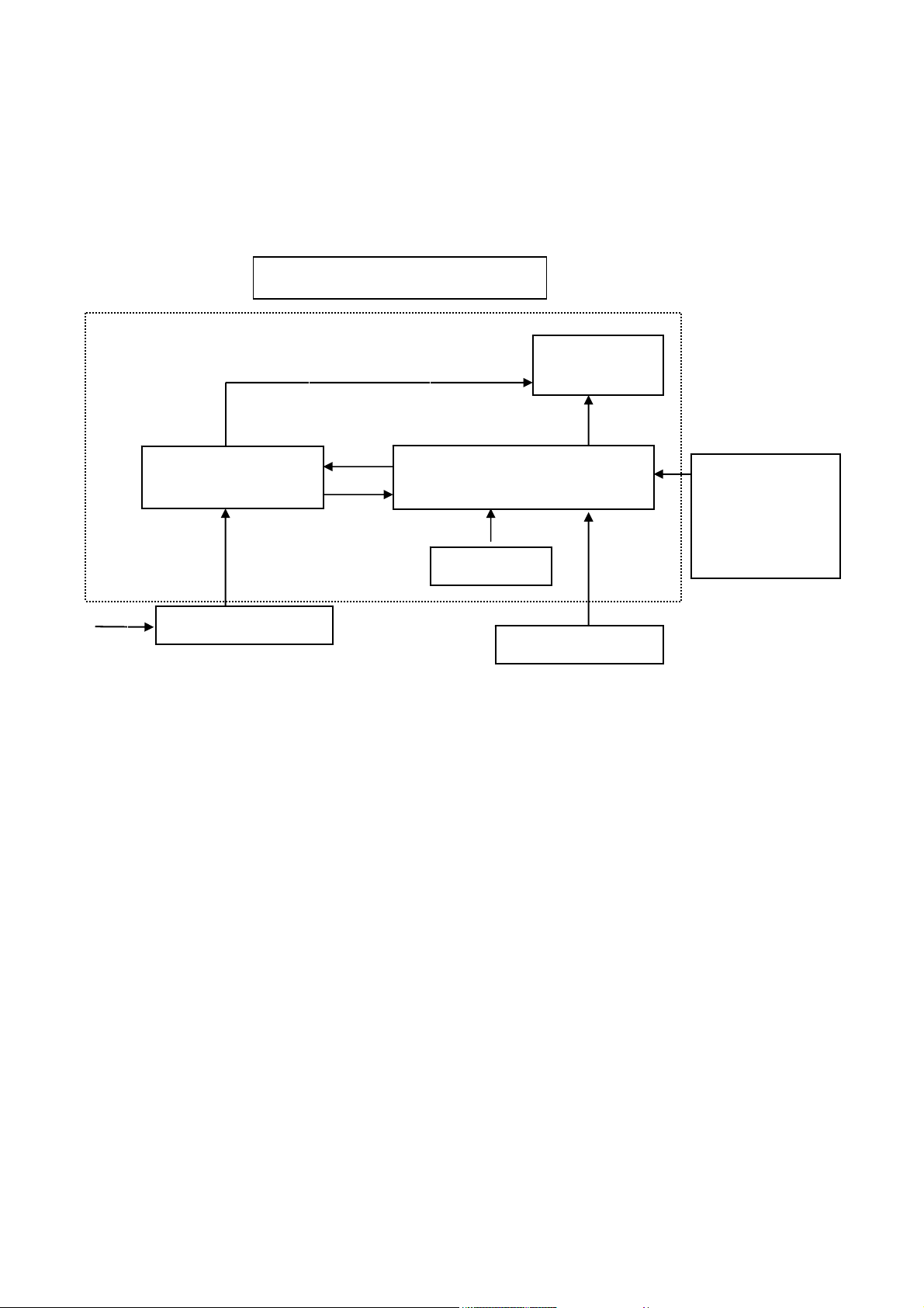
2. LCD MONITOR DESCRIPTION
The LCD MONITOR will contain an main board, an power board, key board and external adapter which house
the flat panel control logic, brightness control logic and DDC.
The power board will drive the backlight of panel and the main board chips each voltage.
An adapter will provide the 12V DC voltage to power conversion board.
AC-IN
90V-264V
Power Board
ADAPTER
Monitor Block Diagram
CCFT Drive.
Main Board
Keyboard
Flat Panel and
CCFL backlight
HOST Computer
RS232 Connector
For white balance
adjustment in
factory mode
Video signal, DDC
6
Page 7
HP Mannequin (f1503) Service Manual
3. OPERATING INSTRUCTIONS
3.1 General Instructions
Press the power button to turn the monitor on or off. The other control buttons are located at front panel of the monitor. By changing
these settings, the picture can be adjusted to your personal performance.
The power cord should be connected and insert to adaptor.
-
Connect the video cable from the monitor to the computer VGA card.
-
Press the power button to turn on the monitor, the power indicator will light up to blue.
-
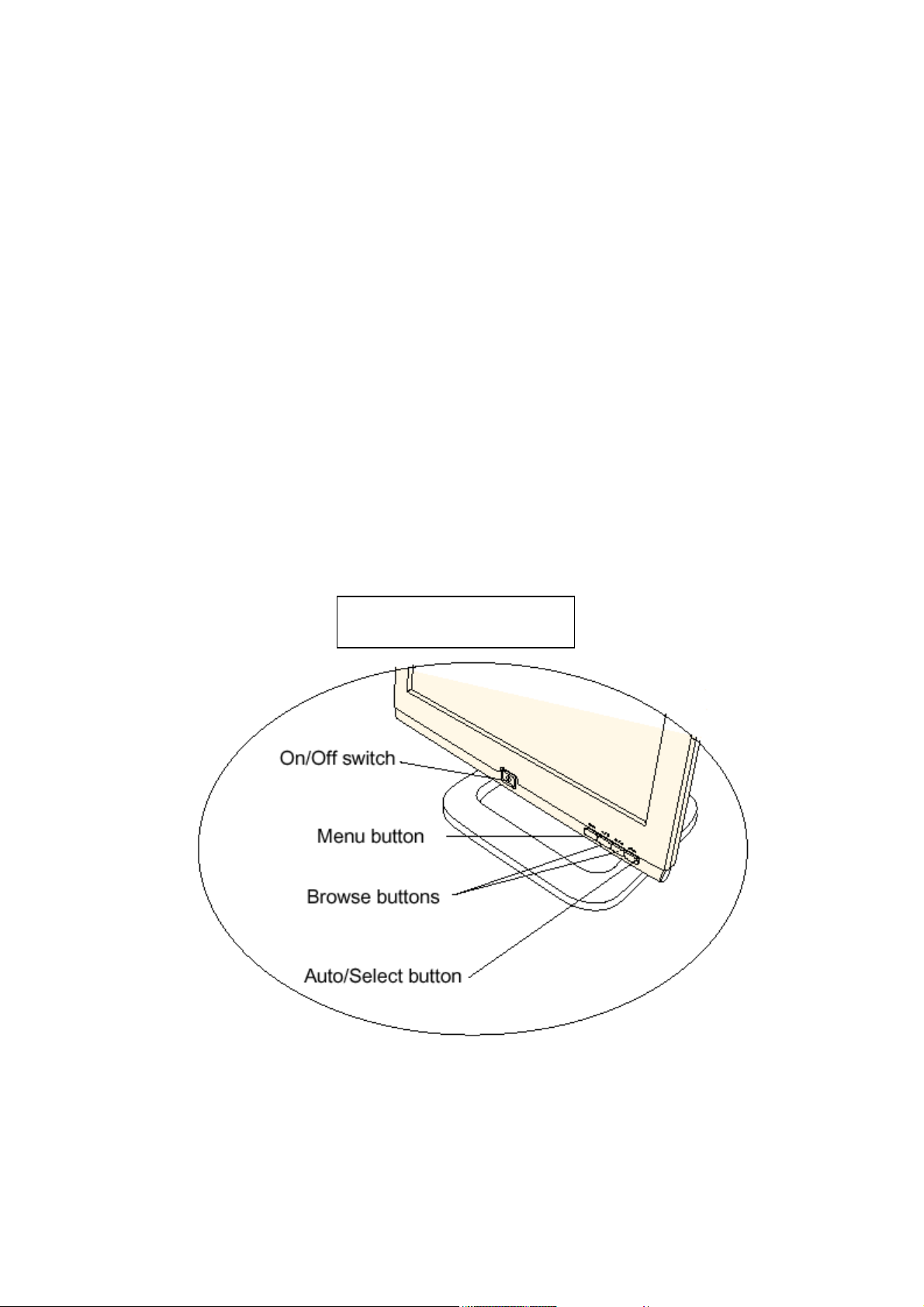
3.2 Control Buttons
Power Button:
-
When pressed, the monitor enters the off mode, and the LED turns blank. Press again to restore normal status.
- - (Down / Brightness) and + (Up / Contrast) Button:
The -/+ Button is browse OSD key. Press a select into adjustment.
- Auto / Select Key:
The Auto Adjust Key is used to automatically set the H Position, V Position, Clock and Phase.
Select key is into OSD sub-menu hot key when OSD turn on.
- Power Indicator:
Blue — Power On mode.
Amber — Power Saving mode.
Blank — Power Off Mode.
CONTROL Buttons
7
Page 8
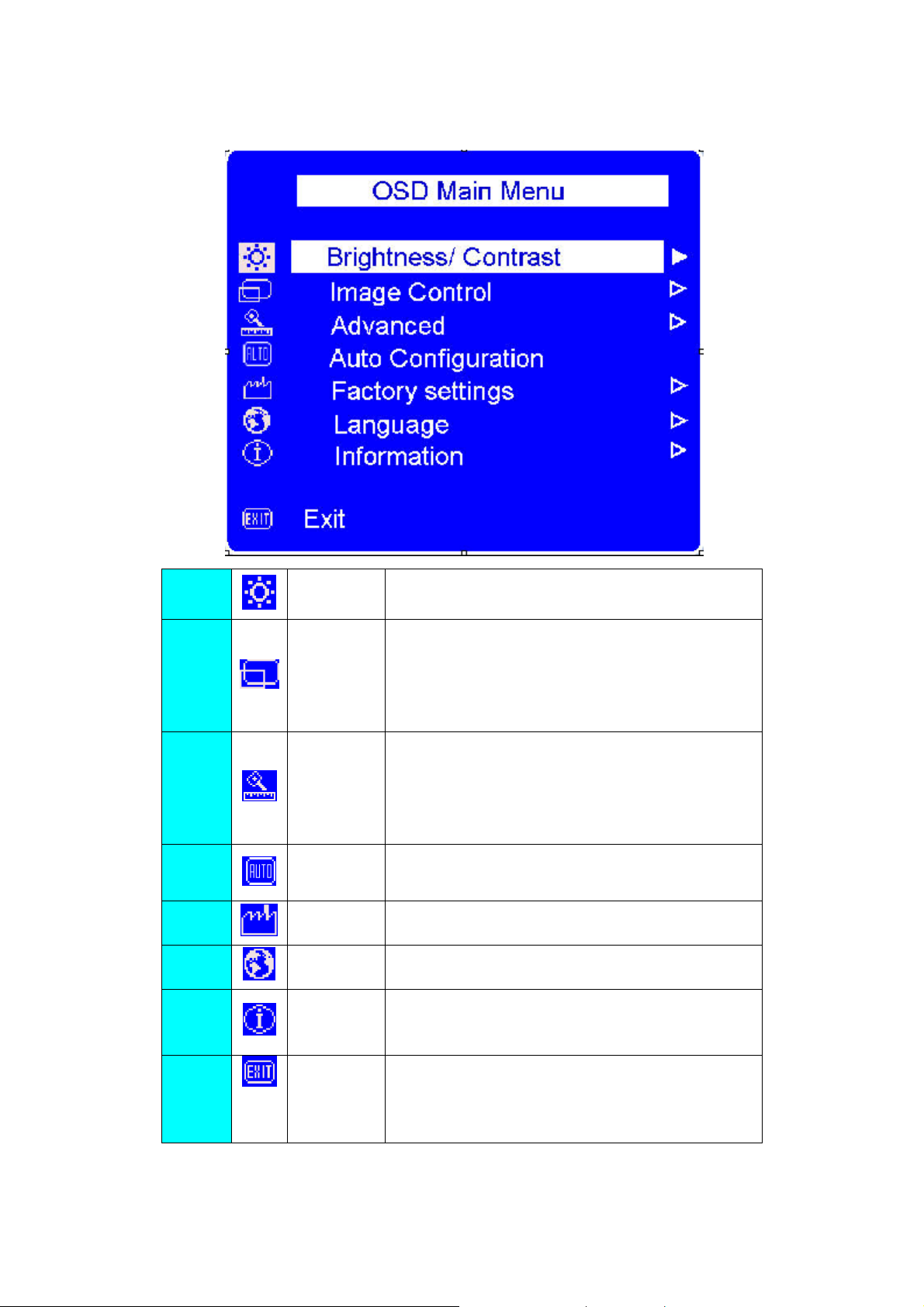
3.3 Adjust The Picture
HP Mannequin (f1503) Service Manual
1.
2.
3. Advance
4.
5.
6.
Brightness/
Contrast
Image Control
Auto
Configuration
Factory
settings
Language Shows the language of the OSD window.
Adjust the brightness or the difference between the light and
dark area.
Adjust the:
z H-Position: horizontal position of the screen image.
z V-Position: vertical position of the screen image.
z Clock: frequency of the pixel clock to minimize vertical
bar.
z Phase: phase value to minimize horizontal jitters.
Displays a sub-menu with two option:
z Color: adjusts the color tint of white, and the red,
green, and blue (RGB) mix for colors.
z OSD (on Screen Display) settings: adjusts the
position, timeout, and notification features of the On
Screen Display window.
Adjusts the main settings and produces a stable, centered
image.
Resets the display to original factory settings for color,
brightness, phase, and clock.
Shows the current resolution and refresh rate;
7. Information
8.
Exit Closes the OSD window.
Shows the serial number of display; shows the power-on
time, and the power-saving time.
8
Page 9

4. Input/Output Specification
4.1 Input Signal Connector
4.1.1 Analog D-SUB Connector
HP Mannequin (f1503) Service Manual
PIN
MNEMONIC
SIGNAL
1 RV Red Video
2 GV Green Video
3 BV Blue Video
4 NC
None (available for mfg use if required)
5 GND Ground (DDC Return)
6 RG Red GND
7 GG Green GND
8 BG Blue GND
9 +5 V +5 V (from PC)
10 SG Sync Ground
11 NC None (available for mfg use if
required)
12 SDA DDC Data
13 HS Horizontal Sync
14 VS Vertical Sync
15 SCL DDC Clock
VGA connector layout
PIN 1
PIN 11
PIN 5
9
Page 10

4.2 Factory Preset Display Modes
HP Mannequin (f1503) Service Manual
Prese
t
Pixel
Format
Horz
Freq
(KHz)
Horz
Polarit
y
Vert
Freq
(Hz)
Vert
Polarity Pixel Clk
(MHz) Source
1 640 x 350 31.469 + 70.086 - 25.175 VGA
2 640 x 480 31.469 - 59.940 - 25.175 VGA
3 640 x 480 37.500 - 75.000 - 31.500 VESA
4 720 x 400 31.469 - 70.087 + 28.322 VGA
5 800 x 600 37.879
+
60.317 + 40.000 VESA
6 800 x 600 46.875 + 75.000 + 49.500 VESA
7 1024 x 768 48.363 - 60.004 - 65.000 VESA
8 1024 x 768 56.476 - 70.069 - 75.000 VESA
9 1024 x 768 60.023 + 75.029 + 78.750 VESA
10
Page 11

HP Mannequin (f1503) Service Manual
)
p
4.3 Power Supply Requirements
4.3.1 Input Requirements
PARA METER RANGE CONDITION
Input Voltage 90 to 264 VAC RMS Universal input full range
Input Frequency 60Hz @ 90VAC to 60Hz @
264VAC
Input Current Less than 2.0 Amps RMS Input voltage 100 VAC RMS ; 60 Hertz. Parameter
must be reached within 3 seconds of turn-on.
Less than 1.0 Amps RMS Input voltage 220 VAC RMS ; 50 Hertz. Parameter
must be reachedwithin 3 seconds of turn-on.
Input Power Less than 75 Watts
Power factor > 0.5 Input voltage 120 VAC RMS ; 60
Hertz
Inrush Current Less than 30 A peak Input voltage 100 VAC RMS ; 60 Hertz at all
Less than 50 A peak Input voltage 240 VAC RMS ; 50 Hertz at all
Input Fusing Fuse should be located internal to the
adapter, easily accessible when the
cover is removed
Leakage Current Less than 3.5 mA Input voltage 264 Volts RMS ; 50 Hertz
Hi-Pot Primary to secondary 1.5KVAC for 1 Minute(leakage current 10mA)
Primary to Saft Ground 1.5KVAC for 1 Minute(leakage current 10mA)
Phase(0, 90, 180, 270 degree)
Phase(0, 90, 180, 270 degree)
Fuse must be UL/CSA approved. Fuse value must no
have to change for 115 VAC or 230 VAC operation
1.8KVAC for 1 Minute(leakage current 10mA)
3.0KVAC for 1 Minute(leakage current 10mA)
without Y-cap & Coupling cap.
1.8KVAC for 1 Minute(leakage current 10mA
4.3.2 Output Requirements
PARAMETER RANGE CONDITION
DC Out 12VDC ± 5% Min 0A Max 3.75A
Load Regulation 12.0V(12.12V) ± 5% 11.4 to 12.6VDC
Dynamic Load
Regulation
Ripple & noise 170mVpp at 12VDC Input voltage: 100VAC at 60Hz & 240VAC at 50Hz
Output current
rotection
Leakage Current Less than 0.25 mA Input voltage 100 Volts RMS ; 50 Hertz
Less than 0.5 mA Input voltage 254 Volts RMS ; 50 Hertz
Any frequency up to 250Hz(duty
50%)
less than 7.0A, more than 12.0A
at 12.0VDC
±5% for 10% to 100%, 100% to 10% load change for
+12Vdc
* Ripple and noise are measured.
Current exceeds maximum rating more than 20%
11
Page 12
4.4 PANEL SPECIFICATION (Hannstar)
4.4.1 Panel Feature
-High contrast ratio
-TN+film (Twisted Nematic) mode
-Wide viewing angle
-XGA (1024 x 768 pixels) resolution
-2 dual CCFTs(Cold Cathode Fluorescent Tube)
-COMPACT SIZE DESIGN
4.4.2 Display Characteristics
Items Specification Unit
Display Area 304.1(H) x 228.1(V) mm
Display color 6 bit dirver Colors
Number of pixels 1024 x 768 pixel
Pixel Arrangement RGB vertical stripe
Pixel pitch 0.297(H) x 0.297(V) mm
Display Mode Normally White
HP Mannequin (f1503) Service Manual
4.4.3 Optical Characteristics
The optical characteristics are measured under stable conditions at 25℃ (Room Temperature):
Item Symbol Conditions Min. Typ. Max. Unit Note
Contrast Ratio
(Center of screen)
Response
Time
White Luminance at CCFL 6mA
(Center of screen)
Color Chromaticity(CIE 1931)
Viewing angle
Brightness Uniformity Buni
Crosstalk [%]
Rising
Falling Tf - -
Hor.
Ver.
C/R
Tr
Normal
YL 200 250 - cd/m
Rx
Ry 0.335
Gx 0.293
Gy 0.599
Bx 0.144
By 0.113
Wx 0.310
Wy 0.330
Θ
L
ΘR 55 65 -
40 45 -
Θ
U
ΘD 50 55 -
ψ=0 degree
θ=0 degree
Viewing
Angle
CR>10
ψ=0 degree
θ=0 degree
300 400 -
-
Typ.
-0.03
55 65 -
70 75 -
- - 1.3
Tr+Tf=35
0.623
Typ.
+0.03
msec
%
%
2
12
Page 13

4.4.4 Parameter guide line for CCFL Inverter
HP Mannequin (f1503) Service Manual
13
Page 14
5. Block Diagram
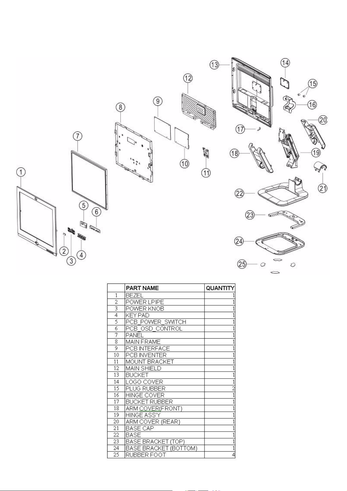
5.1 Monitor Exploded View
5.1.1 f1503
HP Mannequin (f1503) Service Manual
14
Page 15
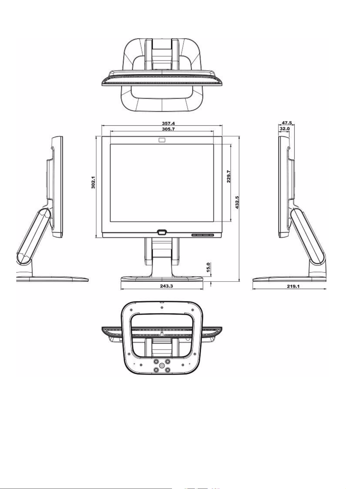
5.1.2 f1503
HP Mannequin (f1503) Service Manual
15
Page 16
HP Mannequin (f1503) Service Manual
2
10
12
6
4
3
8
9 141113
1516
1719
18
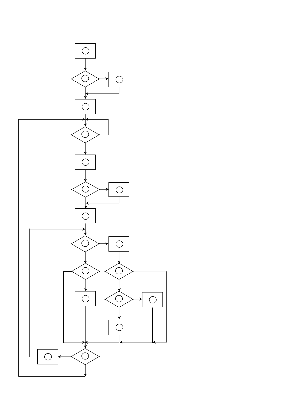
5.2 Software Flow Chart
eeprom. Check the pin PANEL1 and PANEL2
Turn on the LED and set it to green color.
Scalar initializes.
any signals coming?
digital port?
standby mode after the message disappear.
mode.
1
5
7
1) MCU initialize.
2) Is the eeprom blank?
3) Program the eeprom by default values.
4) Get the PWM value of brightness from
to tell which panel to get with it.
5) Is the power key pressed?
6) Clear all global flags.
7) Are the AUTO and SELECT keys pressed?
8) Enter factory mode.
9) Saving the power key status into eeprom.
10) In standby mode?
11) Update the lifetime of back light.
12) Check the analog and digital port, are there
13) Does the scalar send out a interrupt request?
14) Wake up the scalar.
15) Are there any signals coming from analog or
16) Display "No Signals" message. And go into
17) Program the scalar to be able to show the coming
18) Process the OSD display.
19) Read the keyboard. Is the power key pressed?
16
Page 17

5.3 Electrical Block Diagram
5.3.1 Main Board
HP Mannequin (f1503) Service Manual
17
Page 18

6. Schematic
6.1 Main Board
HP Mannequin (f1503) Service Manual
CONTENTS
SCHEMATIC
Title Page
ADE3200
Input Interface
Damping Resister
Output Interface
8051 Microcontroller
Board Power Supply
SHEET
1
2
3
4
5
6
7
715L-1018-1
ADE3000T 15" LCD Control Board Rev.D
Mannequin 15"
TF1562-2A
Hannstar HSD150SX84
Title
Size Document Number Rev
Date: Sheet of
星期一, 三月
ADE3000 LCD Control Board
Title Page & circuit block
24, 2003
18
0.1
18
Page 19

AVDD_1.8
12
C3
+
C1
10uF/6.3V
22uF/16V
RV2_6
C39
22uF/16V
RV2_6
DVDD_1.8
Distribute the 4 resisters arround the
top of AGND plane.
1206
12
+
10uF/6.3V
1206
AVDD_1.8
FB7
60OHM
REFCR
REFR
R1
C60
15K 1/16W
0.1uF/16V
REFG
REFCG
R3
C63
15K 1/16W
0.1uF/16V
REFCB
REFB
R5
C66
15K 1/16W
0.1uF/16V
INTERNAL ADC REFERENCE
RESISTORS AND DECOUPLING
CAPACITORS. PLACE THESE
COMPONENTS CLOSE TO THEIR
RESPECTIVE PINS
DVDD_3.3
FB6
60OHM
R138 0 1/16W
R139 0 1/16W
R140 0 1/16W
R141 0 1/16W
AVDD_3.3
C49
C4
C5
0.1uF/16V
0.1uF/16V
C50
C51
0.1uF/16V
0.1uF/16V
0.1uF/16V
PLACE CAPACITORS ON PINS 14,
38, AND 42, RESPECTIVELY
(TMDS power supply pins)
REFPR
C58
C59
R2
100pF
0.47uF/16V
NP
REFMR
REFPG
C61
C62
R4
100pF
0.47uF/16V
NP
REFMG
REFPB
C64
C65
R6
100pF
0.47uF/16V
NP
REFMB
AVDD_3.3
C130
0.1uF/16V
C6
C7
0.1uF/16V
0.1uF/16V
C53
C52
0.1uF/16V
AVDD_1.8
C55
0.1uF/16V
INR(3)
ING(3)
INB(3)
RVDD_3.3
FB4
60OHM
no via, same
layer
same lenth,and
parallel
The OCLK should have third
priority and be shielded with GND.
(short,straight connection on top
layer only)
0.1uF/16V
ADE-RESET#(6)
AHSYNC(3)
AVSYNC(3)
FB2
60OHM
FB3
60OHM
RVDD_1.8
C56
Close to U1
C75 0.1uF/16V
C76 0.1uF/16V
C77 0.1uF/16V
475 1/16W(NC)
C67
0.1uF/16V
ADE-SCL(6)
ADE-SDA(6)
C57
0.001uF
C71
10pF
FB1
60OHM
XVDD_1.8
LVDD_1.8
R19
R22
R24
R7
2K 1/16W(NC)
DVDD_3.3
C37
0.1uF/16V
C54
0.1uF/16V
R8
TP2
TP4
TP6
TP8
TP10 1
R12
1M(NC)
27MHz
C11
0.1uF/16V
10 1/16W
10 1/16W
10 1/16W
TP1
1
TP3
1
TP5
1
TP7
1
TP9
C68 0.001uF
Y1
PVDD_1.8
0.1uF/16V
R9
4.7K 1/16W
R10 0 1/16W
C72
15pF
AVDD_3.3
C12
92
80
68
55
54
53
183
REFR
87
REFCR
95
REFPR
89
REFMR OGA3
88
REFG
75
REFCG
83
REFPG
77
REFMG
76
REFB
63
REFCB
71
REFPB
65
REFMB
64
16
17
20
21
23
24
27
28
30
36
7
YUV0
1
YUV1
6
5
YUV2
1
4
YUV3
3
YUV4
1
YUV5
2
YUV6
1
1
208
YUV7
8
1
YUVCLK
203
204
207
184
206
99
48
49
C15
C14
0.01uF
DVDD_1.8
U1
INR
ING
INB
HSYNC
VSYNC
CSYNC
CLKIN
REFR
REFCR
REFPR
REFMR
REFG
REFCG
REFPG
REFMG
REFB
REFCB
REFPB
REFMB
RX2M
RX2P
RX1M
RX1P
RX0M
RX0P
RXCP
RXCM
REXT
RBIAS
YUV0
YUV1
YUV2
YUV3
YUV4
YUV5
YUV6
YUV7
YUVCLK
SCL
SDA
RESETN
TCON_IN
XCLK_EN
TST_SCAN
XTAL_IN
XTAL_OUT
C13
9
DVDD18
C16
0.1uF/16V
100pF
0.001uF
PLACE CAPACITORS C14, C15, C16, C17, C18,
C19, AND C20 ON PINS 15, 19, 22, 25, 29, (31 &
32), AND 40, RESPECTIVELY
(TMDS power supply pins)
121
123
140
142
164
166
178
180
191
193
199
DVDD18
DVDD18
DVDD18
DVDD18
DVDD18
DVDD18
DVDD18
DVDD18
DVDD18
DVDD18
DGND
DGND
DGND
DGND
DGND
DGND
DGND
DNGD
DGND
DGND DVDD18
DGND
10 11
12
100
105
112
122
124
135
141
143
149
159
DVDD_3.3
201
DVDD18
DVDD18
DGND
DGND
165
167
C17
0.01uF
101
DGND
173
111
125
DVDD33
DVDD33
DGND
DGND
179
181
0.1uF/16V
134
DVDD33
DGND
186
C18
148
158
172
DVDD33
DVDD33
DVDD33
DVDD33
DGND
DGND
DGND
DGND
192
194
200
RVDD_3.3
C19
0.01uF
AVDD_3.3
AVDD_1.8
185
61737485869798
AVDD18
AVDD18
AVDD18
AVDD18
AVDD18
AVDD18
DVDD33
ADE3000T
DGND
AGND
AGND
AGND
AGND
AGND
AGND
202
56576062666772787984909196
12
+
C2
22uF/16V
RV2_6
12
+
C38
22uF/16V
RV2_6
58596970818293
AVDD18
AVDD33
AGND
AGND
AGND
AVDD33
AVDD33
AVDD33
AVDD33
AVDD33
AGND
AGND
AGND
AGND
1318263334353739414345
10uF/6.3V
10uF/6.3V
RVDD_1.8
94
AVDD33
AVDD33
RGND
RGND
DVDD_1.8
C20
1206
DVDD_3.3
C40
1206
143842
15192225293132
RVDD18
RVDD18
RVDD18
RVDD33
RGND
RGND
RGND
RGND
RGND
RGND
HP Mannequin (f1503) Service Manual
C44
0.1uF/16V
XVDD_1.8
C183
1uF/16V
LVDD_1.8
C24
0.1uF/16V
OBA7
OBA6
OBA5
OBA4
OBA3
OBA2
OBA1
OBA0
OGA7
OGA6
OGA5
OGA4
OGA2
OGA1
OGA0
ORA7
ORA6
ORA5
ORA4
ORA3
ORA2
ORA1
ORA0
OBB7
OBB6
OBB5
OBB4
OBB3
OBB2
OBB1
OBB0
OGB7
OGB6
OGB5
OGB4
OGB3
OGB2
OGB1
OGB0
ORB7
ORB6
ORB5
ORB4
ORB3
ORB2
ORB1
ORB0
TCON0
TCON1
TCON2
TCON3
TCON4
TCON5
TCON6
TCON7
0.1uF/16V
C73
0.1uF/16V
C45
0.1uF/16V
C25
C184
1uF/16V
C69
NP_C
C26
C27
0.1uF/16V
0.1uF/16V
0.1uF/16V
C46
C47
0.1uF/16V
0.1uF/16V
OBA[7:0] (4)
OGA[7:0] (4)
ORA[7:0] (4)
OBB[7:0] (4)
OGB[7:0] (4)
ORB[7:0] (4)
OCLK (5)
ODE (5)
OHS (5)
OVS (5)
TCON[7:0] (5)
The TCON[0..7], ODE, OHS and
OVS are the fourth priority.
R11 0 1/16W
C70
NP_C
C28
MCU-CLK
C31
C30
C29
0.1uF/16V
0.1uF/16V
0.1uF/16V
C48
0.1uF/16V
MCU-CLK (6)
AOC
Title
ADE3000 LCD Control Board
Size Document Number Rev
ADE3000
Date: Sheet
星期三, 三月
19, 20 03
0.1uF/16V
RVDD_3.3
RVDD33
RGND
RVDD33
C21
10uF/6.3V
1206
0.1uF/16V
RVDD33
RVDD33
PGND
PGND
C41
PVDD_1.8
40
RVDD33
RVDD33
XGND
47
C22
10uF/6.3V
1206
C42
0.1uF/16V
C182
1uF/16V
44
46
51
PVDD18
PVDD18
RVDD33
R13 0 1/16W
LVDD18
LVDD_1.8
TCON0
TCON1
TCON2
TCON3
TCON4
TCON5
TCON6
TCON7
CLKOUT
C43
0.1uF/16V
50
XVDD18
ORA0
ORA1
ORA2
ORA3
ORA4
ORA5
ORA6
ORA7
OGA0
OGA1
OGA2
OGA3
OGA4
OGA5
OGA6
OGA7
OBA0
OBA1
OBA2
OBA3
OBA4
OBA5
OBA6
OBA7
ORB0
ORB1
ORB2
ORB3
ORB4
ORB5
ORB6
ORB7
OGB0
OGB1
OGB2
OGB3
OGB4
OGB5
OGB6
OGB7
OBB0
OBB1
OBB2
OBB3
OBB4
OBB5
OBB6
OBB7
OCLK
ODE
OHS
OVS
XCLK
LGND
52
C23
0.1uF/16V
133
132
131
130
129
128
127
126
120
119
118
117
116
115
114
113
110
109
108
107
106
104
103
102
177
176
175
174
171
170
169
168
163
162
161
160
157
156
155
154
153
152
151
150
147
146
145
144
138
136
137
139
198
197
196
195
190
189
188
187
205
182
C33
C32
0.1uF/16V
0.1uF/16V
every 8 signal = one group
same lenth and parallel in
one group , shielding with
GND in one group , put
via on GND
C34
C35
0.1uF/16V
28
of
C36
0.1uF/16V
0.1
19
Page 20

3.3K 1/16W
R14
1
BAT54C
2
3
TZMC5V6-GS08
+5V
3 2
0.1uF/16V
R15
3.3K 1/16W
ZD2
BAT54CFILM
C74
SOD123
HP Mannequin (f1503) Service Manual
VGA_5V
D1
D2
1
DIODE_23(NP)
1 2
D3
BAV99
23
1
ED2
ED3
DIODE_23(NP)
1 2
1 2
1
ZD3
TZMC5V6-GS08
SOD123
7
6
5
M24C02WMN6
10K 1/16W
VCC
SCL
SDA
R28
A0
2
A1A2WP
3
4
GND
DDC-SCL (6)
DDC-SDA (6)
ZD4
SOD123
+5V
CN1
VGA_5V
R16
10K 1/16W
A-DETECT(6)
RXD(6)
R168
DB15_SDA
47 1/16W
DB15-AHSYNC
DB15-AVSYNC
R169
DB15_SCL
47 1/16W
ZD5
R29
10K 1/16W
TZMC5V6-GS08
TZMC5V6-GS08
SOD123
TXD(6)
DB15
9
10
11
12
13
14
15
17
Analog Input (VGA)
1
2
3
4
5
6
7
8
16
U2
1
8
RED
GREEN
BLUE
BAV99
trace 16mil
ED1
DIODE_23(NP)
23
150 1/16W
147
13 12
DB15-AVSYNC
147
5 6
DB15-AHSYNC
147
11 10
147
9 8
AVDD_3.3
1
D4
BAV99
R25
U3F
74F14
U3C
74F14
U3E
74F14
BAV99
2
3
23
1
R18 200 1/16W
R21 200 1/16W
R23 200 1/16W
150 1/16W
150 1/16W
150 1/16W
150 1/16W
R172
U3D
74F14
C86
0.1uF/16V
R26
0 1/16W
0 1/16W
R151
150 1/16W
R173
R27
R167
Shielding with GND
CLOSE TO CN1
+5V
R174
3 4
C188
47pF
1 2
C185
47pF
Highest Priority to input RED, GREEN, BLUE and A_HSYNC (from
CON3 to U1). The route width of RED, GREEN, BLUE and A_HSYNC
should be larger than 16 mils. The signals should be on the top layer
with no via, the length is less than 5 cm for better picture quality
(short,
straight connection on top layer).
C79
C78
10pF(NC)
10pF(NC)
147
147
10pF(NC)
R30
U3B
33 1/16W
74F14
R31
U3A
33 1/16W
74F14
INPUT INTERFACE
FB18 300OHM
FB19 300 OHM
FB20 300 OHM
C80
trace 16 mils (minimum)
C189
NP_C
C83
27pF
Shielding with GND
AVSYNC (2)
AHSYNC (2)
INR (2)
ING (2)
INB (2)
AOC
Title
Size Document Number Rev
Date: Sheet of
星期一, 三月
ADE3000 LCD Control Board
Input Interface
24, 2003
38
0.1
OUTPUT INTERFACE
ORA[7:0](2)
OGA[7:0](2)
OBA[7:0](2)
RP1
4
ORA0
3
ORA1
2
ORA2
ORA3
1
22 1/16W
RP3
ORA4
1
ORA5
2
ORA6
3
ORA7
4
22 1/16W
RP5
OGA0
4
OGA1
3
OGA2
2
OGA3
1
22 1/16W
RP7
OGA4
4
OGA5
3
OGA6
2
OGA7
1
22 1/16W
RP9
OBA0
4
OBA1
3
OBA2
2
OBA3
1
22 1/16W
OBA4
4
OBA5
3
OBA6
2
OBA7
1
RP11
22 1/16W
RA0
5
RA1
6
RA2
7
RA3
8
8
7
6
5
5
6
7
8
5
6
7
8
5
6
7
8
678
CP1
NP-8P4C
123
4 5
RA4
RA5
RA6
RA7
678
CP3
NP-8P4C
123
4 5
GA0
GA1
GA2
GA3
678
CP5
NP-8P4C
123
4 5
GA4
GA5
GA6
GA7
678
CP7
NP-8P4C
123
4 5
BA0
BA1
BA2
BA3
678
CP9
NP-8P4C
123
4 5
BA4
5
BA5
6
BA6
7
BA7
8
678
CP11
NP-8P4C
123
4 5
RA[7:0] (5)
GA[7:0] (5)
BA[7:0] (5)
ORB[7:0](2)
OGB[7:0](2)
OBB[7:0](2)
RP2
ORB0
4
ORB1
3
ORB2
2
ORB3
1
22 1/16W
RP4
ORB5
1
2
ORB4
ORB6
3
ORB7
4
22 1/16W
RP6
OGB0
4
OGB1
3
OGB2
2
OGB3
1
22 1/16W
RP8
OGB4
4
OGB5
3
OGB6
2
OGB7
1
22 1/16W
RP10
OBB0
4
OBB1
3
OBB2
2
OBB3
1
22 1/16W
RP12
OBB4
4
OBB5
3
OBB6
2
OBB7
1
22 1/16W
RB0
5
RB1
6
RB2
7
RB3
8
8
7
6
5
5
6
7
8
5
6
7
8
5
6
7
8
5
6
7
8
678
CP2
NP-8P4C
123
4 5
RB5
RB4
RB6
RB7
678
CP4
NP-8P4C
123
4 5
GB0
GB1
GB2
GB3
678
CP6
NP-8P4C
123
4 5
GB4
GB5
GB6
GB7
678
CP8
NP-8P4C
123
4 5
BB0
BB1
BB2
BB3
678
CP10
NP-8P4C
123
4 5
BB4
BB5
BB6
BB7
678
CP12
NP-8P4C
123
4 5
RB[7:0] (5)
GB[7:0] (5)
BB[7:0] (5)
AOC
Title
Size Document Number Rev
Date: Sheet of
星期一, 三月
ADE3000 LCD Control Board
Output Interface
24, 2003
48
0.1
20
Page 21

3
2
1
B
E
MMBT3904
LCD_+A5V
R56 10K 1/16W
PWSVLCD(6)
OVS(2)
OHS(2)
ODE(2)
OCLK(2)
sheilding with GND
TCON[7..0](2)
R50
10K 1/16W
+
OVS
OHS
ODE
OCLK
TCON0
TCON1
TCON2
TCON3
TCON4
TCON5
TCON6
TCON7
LCD_+5V
R132
NP
C176
4.7uF/16V
R46 22 1/16W
R47 22 1/16W
R48 22 1/16W
R49 22 1/16W
C145
NP
R110 22 1/16W
R111 22 1/16W
R112 22 1/16W
R113 22 1/16W
R115 22 1/16W
R116 22 1/16W
R117 22 1/16W
R118 22 1/16W
LCD_+3.3V
C147
0.1uF/16V
Q3
PMBS3904
R133
0 1/16W
C93
NP
C149
NP
C153
NP
U7
1
S1
2
G1
3
S2
4
G2
P-MOS
STS3DPF30L
C94
NP
C150
NP
C154
NP
D1
D1
D2
D2
Close to U1
AUO
CLAA
HSD
150SX84
N/A
OVS
REV
ODE
STH
TCON0
LOAD
TCON1
POL
TCON2
N/A
TCON3
STV1
TCON4
STV2
TCON5
CPV
TCON6
OE
TCON7
OCLK 9.2V 200mA
CPH1/CPH2
150XG02
HMS2_E
HMS1_O
STH
LP
POL
N/A
STV
N/A
CLKV
N/A
CLKH
M150XS03-1
XOPOL2
XEPOL2
XDIO
XSTB
XPOL
YXAO
YDIO1
YDIO2
YCLK
YOE
XCLK
VDDG
VCOM
VEEG
VDDA
C100
22uF/16V
RV2_6
12
+
LCD_+A3.3V
C101
22uF/16V
RV2_6
VLCD
FB10
60OHM
C102
0.1uF/16V
C95
NP
FB9
60OHM
8
7
6
5
LCD_+5V
彩絬 ぶ
30mils
12
+
FPVS
FPHS
REV
FPCLK
C96
NP
sheilding with GND
STH
LOAD
POL
YXAO
R114 NP
C151
C152
NP
NP
STV1
STV2
CPV
OE
C155
C156
NP
NP
CPT CLAA150XG02 PANEL DC-DC VS AU M150XS03-1
18V 58mA
3.95V 200mA
-6V 10mA
for
AU
VON
26V 2mA
YVEE
-16V 20mA
-4.5V 2mA
VL
V90
8.8V 200mA
LCD_+3.3V
10K 1/16W
LCD_DDON (7)
R134
for AU
R? NP
HP Mannequin (f1503) Service Manual
OUTPUT INTERFACE
VDDA
CN7
1
NC
2
NC
3
GND
BB5
BB4
BB3
BB2
BB1
BB0
GB5
GB4
GB3
GB2
GB1
GB0
RB5
RB4
RB3
RB2
RB1
RB0
FPCLK
STH
LOAD
POL
REV
STV1
STV2
CPV
OE
BA5
BA4
BA3
BA2
BA1
BA0
GA5
GA4
GA3
GA2
GA1
GA0
RA5
RA4
RA3
RA2
RA1
RA0
FPCLK
R119 NP
R120 NP
HMS2_E
4
GND
5
EB5
6
EB4
7
EB3
8
EB2
9
EB1
10
EB0
11
GND
12
EG5
13
EG4
14
EG3
15
EG2
16
EG1
17
EG0
18
GND
19
ER5
20
ER4
21
ER3
22
ER2
23
ER1
24
ER0
25
GND
26
CPH1
27
GND
28
GND
29
STH
30
LOAD
31
POL
32
REV
33
GND
34
GND
35
STV1
36
STV2
37
CPV
38
OE
39
GND
40
GND
CONN
FIRST PIXEL
VLCD
CN8
1
NC
2
NC
3
GND
4
GND
5
EB5
6
EB4
7
EB3
8
EB2
9
EB1
10
EB0
11
GND
12
EG5
13
EG4
14
EG3
15
EG2
16
EG1
17
EG0
18
GND
19
ER5
20
ER4
21
ER3
22
ER2
23
ER1
24
ER0
25
GND
26
CPH1
27
GND
28
GND
29
STH
30
LOAD
31
POL
32
REV
33
GND
34
GND
35
STV1
36
STV2
37
CPV
38
OE
39
GND
40
GND
CONN
FIRST PIXEL
58
LAST PIXEL
for CPT
, AU
YXAO
BB[7:0](4)
GB[5:0](4)
RB[5:0](4)
REV:
for CPT
HMS1_O
BA[5:0](4)
GA[5:0](4)
RA[5:0](4)
VDDG
VEEG
VCOM
R121 NP
YXAO
R122 NP
FPVS
REV
R123 NP
Flat Panel Data Output For HSD smartpanel
SET 0x0C30 to 2F.
option for
test
AOC
Title
Size Document Number Rev
Date: Sheet of
星期一, 三月
ADE3000 LCD Control Board
Output Interface
24, 2003
0.1
21
Page 22

ADE-SCL(2)
ADE-SDA(2)
DGND
DGND
IGND and DGND are isolated,
not completely separated,
connected together near the
power connector
+5V
R73
3.3K 1/16W
CN6
LCD_VCC
CONN
IGND
3.3K 1/16W
EPR-SCL
EPR-SDA
4.7K 1/16W
EPR_EN
BLON
BRI_CON
+A5V
+5V
GND
+3.3V
GND
+1.8V
GND
+12V
LIN_L
GND
LIN_R
1pin = 1A
CN9
1
2
3
4
R74
3.3K 1/16W
R84
3.3K 1/16W
+5V
R145
1
2
3
4
5
6
7
8
9
10
FB8 60OHM(NC)
11
12
13
14
+5V
C173
2.2 uF
R131
3.3K
+5V
R154
47 1/16W
DDC-SDA(3)
MCU-CLK(2)
+5V
R85
R90 0 1/16W
ADE3200 POWER CONSUMPTION
R104 NC
R105 NC
D20
1N4148
RESET
R153
1 2
0 1/16W
BRIGHTNESS(7)
R155
47 1/16W
RXD
RXD(3)
TXD
TXD(3)
EPR-SDA
EPR-SCL
DDC-SCL(3)
R78 0 1/16W(NC)
C113
33pF
U9 M24256
8
A0
VCC
7
A1A2TEST
6
SCL
5
SDA
GND
ST7 EEPROM
XGA
0.7A
1.8V
0.16A
3.3V 0.23A
+12V
LIN_L
LIN_R
0.1uF/16V
TP11
TP12
TP13
TP14
TP15
TP16
TP17
R170 47 1/16W
R171 47 1/16W
R157 47 1/16W
R158 47 1/16W
R159 47 1/16W
R160 47 1/16W
R17 47 1/16W
R20 47 1/16W
C115
0.1uF/16V
1
2
3
4
SXGA
0.91A
12
+
C186
1
1
1
1
1
1
1
RESET
R80
1M(NC)
Y2
20MHz
+5V
C180
22uF/16V
RV2_6
+5V
BRIGHTNESS
LCD_+A3.3V
U11
2
VCC
1
GND
LM810(NC)
SOT23-3
C114
33pF
1
MMBT3904
2
3
12
+
C181
22uF/16V
RV2_6
RESET
LM810
1
2
3
4
5
6
7
8
9
10
11
13
14
15
16
17
18
19
20
21
PMBS3904
3
2
U8
T2/P1.0
T2EX/P1.1
P1.2
P1.3
P1.4
P1.5
P1.6
P1.7
RST
RXD/P3.0
TXD/P3.1
INT0/P3.2
INT1/P3.3
TO/P3.4
T1/P3.5
WR/P3.6
RD/P3.7
XTAL2
XTAL1
3
+5V
Q8
0.1uF/16V
R152
0 1/16W(NC)
C187
0.1uF/16V(NC)
GND
22
CN5
CONN
R98
510 1/16W
R101
10K 1/16W
C121
R165
10K 1/16W
R0603
RESET
8XC51/PLCC
P2.2/A10
P2.3/A11
P2.4/A12
P2.5/A13
P2.6/A14
P2.7/A15
ALE/PROG
P0.7/AD7
P0.6/AD6
P0.5/AD5
P0.4/AD4
P0.3/AD3
P0.2/AD2
P0.1/AD1
P0.0/AD0
NCNCNC
11223
1
2
3
4
5
6
7
8
9
R102
2.7K 1/16W
P2.0/A8
P2.1/A9
PSEN
VCC
EA/VP
34
CP13
1000 pF
+
C177
4.7uF/16V
C123
0.1uF/16V
24
25
26
27
28
29
30
31
32
33
36
37
38
39
40
41
42
43
44
35
NC
BRIGHTNESS (6)
12
+
12
ON/OFF
SEL
RIGHT
LEFT
AUTO
LV-DETECT
PANELID0
A-DETECT
DEBUGGER
EPR_EN
LVDS_EN
ADE-RESET#
PWSVLCD
BLON
LED-ORG
LED-GRN
4327
568
R100
2.7K 1/16W
C125
22uF/16V
RV2_6
+
C131
22uF/16V
RV2_6
10K 1/16W
3.3K 1/16W
0.1uF/16V
+5V
DVDD_3.3
DVDD_1.8
R82
R86
NP
A-DETECT (3)
R142
BLON (7)
C109
1
R99
10K 1/16W
+5V
12
+
C129
0.1uF/16V
C135
0.1uF/16V
10K 1/16W
+5V
R161 4.7K 1/16W
RP13 4.7K 1/16W
C174
1000pF/16V
C122
22uF/16V
RV2_6
ZD1
MLL740A
+5V
R63
PWSVLCD (5)
1
8
2
7
3
6
4
5
BLON (6)
12
R163
10K 1/16W
R0603
R164
10K 1/16W
R0603
R166
10K 1/16W
R0603
1
MMBT3904
3
R87
47K 1/16W
+
C178
22uF/16V
RV2_6
HP Mannequin (f1503) Service Manual
8051 MICROCONTROLLER
+5V
R65
JP4
1K 1/16W
10K 1/16W
R0603
1
0
R89
1K 1/16W
星期一, 三月
PMBS3906
PMBS3906
R97
PANELID0
R68
NC
R0603
DEBUGGER
+5V
Q6
+5V
Q7
ADE3000 LCD Control Board
8051 Microcontroller
24, 2003
BOARD POWER SUPPLY
JP4
1
2
NP
JUMP ON: DEBUG MODE
JUMP OFF: NORMAL
R83
1K 1/16W
R135
1K 1/16W
R91
1K 1/16W
R136
1K 1/16W
+5V
2
C111
0.1uF/16V
+5V
+5V
B-LED1
O-LED1
ON/OFF
SEL
RIGHT
LEFT
AUTO
LCD_+A5V
Q5
PMBS3904
LV-DETECT
R88
1K 1/16W
R66
200K 1/16W
12
+
C179
22uF/16V
RV2_6
LVDS_EN
ADE-RESET# (2)
R162
10K 1/16W
R0603
HSD
CPT
0 : JUMP ON
1 : JUMP OFF
ゅ
B-LED1
O-LED1
AOC
Title
Size Document Number Rev
Date: Sheet of
R156
10K 1/16W
R0603
JP1
1
2
NP
LED-GRN
LED-ORG
68
0.1
LCD_DDON(5)
300mA
+5V
C157
47uF/16V
Distribe the resisters around
the top of AGND plane.
DIP PIN PITCH 2.0
U10 DC/DC_M1
2
R126 10K 1/16W
+
C158
C159
1uF/6.3V
0.1uF/16V
VIN
3
VIN
4
ON/OFF
5
GND
6
GND
7
VR(30K)
VDD+9V
R128 NP
+
C160
47uF/16V
keep clear on top lays
under this board
VGHNC
VGC
GND
GND
VGL
NC
C161
47uF/16V
R124 NP
141
R125 NP
13
12
11
10
R127 NP
9
8
+
C163
C162
0.001uF
1uF/6.3V
DGND
Capacitor close to
this board
C164
0.1uF/16V
VR1
10K
C165
C166
+
0.001uF
4.7uF/16V
* Exchange C166 and
C169 Polarity
C167
0.1uF/16V
C168
0.001uF
+
4.7uF/16V
VDDG
VCOM
VEEG
C170
0.1uF/16V
C171
1uF/6.3V
C169
+
4.7uF/16V
VDDA
C172
AOC
Title
Size Document Number Rev
Date: Sheet
星期一, 三月
ADE3000 LCD Control Board
Board Power Supply
24, 2003
of
78
0.1
22
Page 23

6.2 Power Board
HP Mannequin (f1503) Service Manual
23
Page 24

6.3 Key Board
CN103
B-LED1
1
1
2
GND
2
O-LED1
3
3
ON/OFF
4
4
5
SEL
5
6
RIGHT
6
7
LEFT
7
8
MENU
8
9
9
NC
CN102
1
SEL
RIGHT
2
LEFT
3
CONN
4
5
MENU
GND
HP Mannequin (f1503) Service Manual
43
21
LED101
Y
4
2
1
BLUE
B
3 2
GND
MHB10-1411QBQYC
3
1
AMBER
SW105
POWER
CN101
1
2
3
4
5
NC
AOC
Title
Size Document Number Rev
B
Date: Sheet
1
SEL
2
RIGHT
3
LEFT
MENU
4
5
GND
SW103
SW104
MENU
LEFT
SW102
RIGHT
SW101
SEL
ADE3300 LCD Control Board
Power Key,LED board 0.1
of
11Thursday, November 14, 2002
AOC
Title
Size Document Number Rev
B
Date: Sheet
ADE3300 LCD Control Board
OSD Key 0.1
of
11Monday, September 30, 2002
24
Page 25

7. PCB Layout
7.1 Main Board
HP Mannequin (f1503) Service Manual
25
Page 26

7.2 Power Board
HP Mannequin (f1503) Service Manual
26
Page 27

7.3 Key Board
HP Mannequin (f1503) Service Manual
27
Page 28

HP Mannequin (f1503) Service Manual
8. Maintainability
8.1 Equipments and Tools Requirement
1.) Multi-meter.
2.) Oscilloscope.
3.) Pattern Generator.
4.) DDC Tool with a IBM Compatible Computer.
5.) Alignment Tool.
6.) LCD Color Analyzer.
7.) Service Manual.
8.) User Manual.
28
Page 29

8.2 Trouble Shooting
8.2.1 Main Board
1.NO SCREEN APPEAR
HP Mannequin (f1503) Service Manual
29
Page 30

HP Mannequin (f1503) Service Manual
30
Page 31

HP Mannequin (f1503) Service Manual
8.2.2 Power Board
8.2.2.1 Basic checks circuit.
1. Measure 12V (F101)Æ5V(F102)Æ3V(F103) can’t open.
2. Measure 1.8V(U102) middle pin should be have 1.8 V output.
3. Use high voltage proble meaure CN201 & CN202(About 640~860 Vrms) if you find abnormal change
PT201 will effect display bright performance.
31
Page 32

8.2.3 Key Board
N N
N
HP Mannequin (f1503) Service Manual
OSD is unstable or not working
Is KeyPad Board connecting normally ?
8.3 Alignment Procedure
Y
Is Button Switch normally ?
Y
Is KeyPad Board Normally ?
Y
Check Main Board
Connect KeyPad Board
Replace Button Switch
Replace KeyPad Board
1.) Pattern generator Output: Timing 1024x768@60hz, Pattern 32 Gray Scale, Analog.
2.) Connect Alignment Tool JP4 with Chroma 7120, JP3 with Monitor Analog Connector, JP4 with Pattern
generator.
3.) Press Menu and Select Button, then Power on Monitor to enter Factor Mode.
4.) Press [SW1] at Alignment Tool.
5.) Change Pattern Generator Pattern to Full White Pattern.
6.) Press [SW2] at Alignment Tool.
7.) Wait LED from OK -> BUSY -> OK.
8.) Press [SW3] once to verify 9300 color temperature.
9.) Press [SW3] once to verify 6500 color temperature.
10.) If there is error at step 7 to 8, repeat step 4 to 9.
32
Page 33

HP Mannequin (f1503) Service Manual
8.4 DDC Writing
8.4.1 DDC Writing Procedure
1.) Plug Power Cable into Monitor, Connect DDC Tool (715A2005-A) from P100 to PC LPT1, J101 with
Monitor Analog (D-Sub) Connector.
2.) Run the DDC software at PC
3.) Key-in Serial Number.
8.4.2 EDID Content
Byte # Description Data Hex Remarks
00 - 07h Header 00, FF, FF, FF, FF, FF, FF, 00
08, 09h Manufacturer Code 0E, 11 HWP
0A, 0Bh Product Code 48, 14
0C - 0Fh Serial Number xx, xx, xx, xx HP Consumer s/n format not supported
10h Week Manufactured xx Refer to Serial Number Encoding specification
11h Year Manufactured xx Refer to Serial Number Encoding specification
12h EDID Version 01 1
13h EDID Revision 03 3
14h Video Input 68 0.700V,0V Analog RGB Color
Separate Syncs
15h Max. Horizontal Size 1E 30 Cm
16h Max. Vertical Size 16 22 Cm
17h Gamma + S/N Encoding xx Refer to Serial Number Encoding specification
18h Feature Support EA DPMS: Standby, Suspend, Active OFF
19 - 22h R, G, B, White xx, xx, xx, xx, xx Chromaticity data
xx, xx, xx, xx, xx Refer to the ColoReal Encoding Specification
23h Timing I AD 720x400@70, 640x480@60, 640x480@72,
640x480@75, 800x600@60
24h Timing II EE 800x600@72, 800x600@75, 832x624@75 (MAC),
1024x768@60, 1024x768@70, 1024x768@75
25h Mfr.’s Reserved Timing 00 Not Used
26 - 35h Standard Timing ID 01, 01, 01, 01, 01, 01, 01, 01, Unused blocks
# 1 - # 8 01, 01, 01, 01, 01, 01, 01, 01
36 - 47h Monitor Descriptor 1 64, 19, 00, 40, 41, 00, Preferred Mode:
26, 30, 18, 88, 36, 00,
2C, DC, 10, 00, 00, 18
48 - 59h Monitor Descriptor 2 00, 00, 00, FD, 00, 38, Vertical : 56 - 75 Hz
4B, 1E, 3D, 08, 00, 0A, Horizontal : 30 - 61 kHz
20, 20, 20, 20, 20, 20 Pixel Clock : 80 MHz GTF not supported
5A - 6Bh Monitor Descriptor 3 00, 00, 00, FC, 00, 43,
4F, 4D, 50, 41, 51, 20, hp f1503
35, 30, 31, 37, 0A, 20
6C - 7Dh Monitor Descriptor 4 00, 00, 00, 0D, 00, 02, COLOREAL DATA
xx, xx, xx, xx, xx, xx Coefficient Value of Red, Green & Blue
xx, xx, xx, xx, xx, xx Refer to the ColoReal Encoding Specification
7Eh Extension 00
7Fh CheckSum xx
33
Page 34

8.4.3 Serial Number Format
The serial number, as defined in Appendix A of label spec 308097, consists of 10 digits as follows:
Where,
XX = The two digit ISO country code for the country of origin (e.g. TW = Taiwan)
S = 1-Digit supplier code (see Table 3 below)
DD = Two digits representing the year & week of production, per the lookup table in label
0 = This is only zero. This will not change.
#### = Four digits of a serial count, where A001 is the first unit produced during the week
of WW and year YY. This count is reset with the date code. For each additional unit
produced, the serial count shall increment by a value of 1. The “000” numbers (B000, C000,
D000, etc.) and letters “I” (Ixxx) and “O” (Oxxx) shall NOT be used.
See Table 3 for the Supplier Serial Number code assignments.
HP Mannequin (f1503) Service Manual
XXSDD0####
spec 308097, Appendix A.
TABLE 3
SUPPLIER SERIAL NUMBER CODES
S/N CHARACTER(S)
Country code (XX) CN
Supplier code (S) C
AOC CODE
34
Page 35

HP Mannequin (f1503) Service Manual
9. Part Lists
Level Location Number Specifacation Item Quantity Uni
*** T560KHKHKHHPA ***
----------------------------------------------------------------------------------------1 ADPC12350BH LCD ADAPTER ASS'Y 88 1.00000 PCS
1 CBPC560KHKHP 15" CONVERSION BOARD 46 1.00000 PCS
1 IDPC5216A1 INVERTER BOARD 58 1.00000 PCS
1 KEPC560KC2 KEY BOARD 41 1.00000 PCS
1 KEPC560KC4 KEY BPARD 86 1.00000 PCS
1 2L6008 1 SCREW 71 2.00000 PCS
1 12L 401 1 CM WASHER 52 2.00000 PCS
1 15L5831 1 MAIN FRAME (H/S X84) 4 1.00000 PCS
1 15L5833 1 MOUNT BRACKET 5 1.00000 PCS
1 23L3178690 3A LOGO 80 1.00000 PCS
1 34L1093 CM B HINGE COVER 59 1.00000 PCS
1 40L 150690 1 ID LABEL 50 1.00000 PCS
1 40L 581 26704 LABEL 49 0.05000 PCS
1 44L3231 8 A EVA WASHER 73 2.00000 PCS
1 44L3231 15 EVA WASHER 81 3.00000 PCS
1 44L3522 1 EPS (L) 19 1.00000 PCS
1 44L3522 2 EPS (R) 20 1.00000 PCS
1 44L3522 3 CARTON 87 1.00000 PCS
1 44L3522 5 U TYPE SHEET 22 1.00000 PCS
1 44L3522624 1A CARTON 65 1.00000 PCS
1 52L 1185 TAPE 90 12.00000 CM
1 52L 1186 TAPE 61 8.00000 CM
1 52L 1208 A TAPE 83 2.00000 PCS
1 52L6020 2HP2 PROTECT FILM 79 1.00000 PCS
1 52L6022 3 SMALL TAPE 89 15.00000 CM
1 71L 100 19 WS ZP 5*12*25 82 2.00000 PCS
1 85L 632 1 SHIELD COVER 25 1.00000 PCS
1 89L 171 35 DC POWER CORD 43 1.00000 PCS
1 89L 173L15 28 SIGNAL CABLE 67 1.00000 PCS
1 89L 176 40 6 FFC CABLE 45 2.00000 PCS
1 89L402L18N YH POWER CORD 72 1.00000 PCS
1 M1L 330 4128 SCREW M3X4 28 1.00000 PCS
1 M1L 330 6128 SCREW (M3X6) 75 2.00000 PCS
1 M1L1725 6120 SCREW (M2.5X6) 84 4.00000 PCS
1 M1L1730 6128 SCREW 76 8.00000 PCS
1 Q1L 330 8120 SCREW 3X8mm 35 12.00000 PCS
1 705L 78HPA SPEAKER 66 1.00000 PCS
1 705L560KB34046 LCD BACK ASS'Y 74 1.00000 PCS
35
Page 36

HP Mannequin (f1503) Service Manual
Level Location Number Specifacation Item Quantity Uni
-----------------------------------------------------------------------------------------
1 750LLH50X84 C SIP PANEL HSD150SX84-C BY HAN 47 1.00000 PCS
1 AM1L1740 14128 SCREW 85 2.00000 PCS
*** ADPC12350BH ***
----------------------------------------------------------------------------------------2 ADPC12350BH6 LCD ADAPTER A6 ASS'Y 247 1.00000 PCS
2 ADPC12400BAI LCD ADAPTER ASS'Y FOR AI 210 1.00000 PCS
2 ADPC12400BSMT LCD ADAPTER ASS'Y FOR SMT 209 1.00000 PCS
2 GND1 9L6002 1 PIN 176 1.00000 PCS
2 40L 45762412A CBPC LABEL 229 2.00000 PCS
2 IC903 56L 139 3 PC123FY2 BY SHARP 3 1.00000 PCS
2 R911 61L152M10457F MOFR 100KOHM +-5% 2W 133 1.00000 PCS
2 C901 63L 107334 5 0.33uF 250V BY TEAPO 146 0.00000 PCS
2 C901 63L107K334 U MPX 0.33UF,275VAC,+-10% 145 1.00000 PCS
2 C902 65L305M1022E3 1000PF +-20% 400VAC BY TDK 235 1.00000 PCS
2 C903 65L305M1022E3 1000PF +-20% 400VAC BY TDK 236 1.00000 PCS
2 C902 65L305M1022EM 1000PF 20% 250V BY MURATA 163 0.00000 PCS
2 C903 65L305M1022EM 1000PF 20% 250V BY MURATA 164 0.00000 PCS
2 C916 65L306M3322F2 3300PF +-20% 250V AC 242 1.00000 PCS
2 C900 65L306M4722B2 4700pF +-20% 250VAC 243 1.00000 PCS
2 C921 67L 215102 3H 1000uf 16V 185 1.00000 PCS
2 C922 67L 215102 3H 1000uf 16V 205 1.00000 PCS
2 C906 67L 305220 7T 22uF +-20% 50V 214 1.00000 PCS
2 C904 67L305S10114H 100UF 400V 18*32mm 105 231 1.00000 PCS
2 71L 55 2 FERRITE BEAD A6 RH 5x6.2x1.6 K 215 1.00000 PCS
2 71L 55 30 FERRITE BEAD 4.3*2*3 100 1.00000 PCS
2 L901 73L 174 26 T1 LINE LILTER 0.45mm 233 1.00000 PCS
2 L902 73L 253 91 H CHOKE COIL 195 1.00000 PCS
2 T901 80L 600 3 T X'FMR BY TDK 193 1.00000 PCS
2 LED1 81L 2 3 2P LED 241 1.00000 PCS
2 F901 84L 53 1 FUSE 2A 250V 230002 218 1.00000 PCS
2 CN901 87L 501 10 AC INLET RIGHT ANGLE 223 1.00000 PCS
2 89L 171509 POWER DC CABLE 245 1.00000 PCS
2 BD901 93L 50460 8 BRIDGE 2KBP06M 2A 400V 89 1.00000 PCS
2 D901 93L 6026T52T FR107 BY TS 194 1.00000 PCS
2 D902 93L 6038P52T PS102R PAN JIT 134 1.00000 PCS
36
Page 37

HP Mannequin (f1503) Service Manual
Level Location Number Specifacation Item Quantity Uni
-----------------------------------------------------------------------------------------
2 705L 560 57 03 Q901 ASS'Y 112 1.00000 PCS
2 705L 560 61 03 R930 ASS'Y 198 1.00000 PCS
2 705L 560 61 04 NR901 ASS'Y 244 1.00000 PCS
2 705L 560 93 03 D911 ASS'Y 111 1.00000 PCS
2 715L 901 1 4 AC-ADAPTOR SHUTTLE BRD 159 1.00000 PCS
*** CBPC560KHKHP ***
----------------------------------------------------------------------------------------2 AIC560KHKHP MAIN BOARD FOR T560K* 8 1.00000 PCS
2 CN5 33L3802 9H WAFER 9P RIGHT ANELE PITCH 1 1.00000 PCS
2 CN6 33L8022 14 H PIN HEADER FEMALE 2*7 90 3 1.00000 PCS
2 40L 457624 1A CPU LABEL 9 1.00000 PCS
2 40L 45762412A CBPC LABEL 13 1.00000 PCS
2 U8 56L1125137H17 W78E65P-40 BY WINBOND 14 1.00000 PCS
2 CN1 88L 35315F HA DB15 RIGHT ANGLE FEMALE 5 1.00000 PCS
2 Y2 93L 22 55 H 20MHZ 15 1.00000 PCS
2 Y1 93L 22 64 CRYSTAL 27 MHZ 49US 7 1.00000 PCS
*** IDPC5216A1 ***
----------------------------------------------------------------------------------------2 IDPC5216A1SMT INVERTER DC TO DC FOR SMT 1 1.00000 PCS
2 CON102 33L800914K H 2*7PIN DUAL ROW RIGHT ANGLE 26 1.00000 PCS
2 40L 45762412A CBPC LABEL 29 1.00000 PCS
2 FILM 52L6025 11511 MICA 30 1.00000 PCS
2 R128 61L152M109 64 1 ohm +-5% 2W 38 1.00000 PCS
2 C210 64L179J1541AT MKT CAP. 0.15UF 100V RSB 12 1.00000 PCS
2 C211 65L 3J2206ET 22PF 5% SL 3KV 13 1.00000 PCS
2 C212 65L 3J2206ET 22PF 5% SL 3KV 15 1.00000 PCS
2 C102 67L215B221 4H 220uF 25V LTR221M1EF11VR HER M 3 1.00000 PCS
2 C101 67L215B471 3H 470uF 16V LTR471M1CF11VR 8*11m 35 1.00000 PCS
2 C112 67L215B471 3H 470uF 16V LTR471M1CF11VR 8*11m 5 1.00000 PCS
2 C113 67L215B471 3H 470uF 16V LTR471M1CF11VR 8*11m 6 1.00000 PCS
2 C116 67L215B471 3H 470uF 16V LTR471M1CF11VR 8*11m 7 1.00000 PCS
2 C117 67L215B471 3H 470uF 16V LTR471M1CF11VR 8*11m 8 1.00000 PCS
2 C201 67L215C151 4H 150uF 25V LZR151M1 10 1.00000 PCS
2 L106 71L 55 19 3.5 X 8.9 X 0.65 32 1.00000 PCS
37
Page 38

HP Mannequin (f1503) Service Manual
Level Location Number Specifacation Item Quantity Uni
-----------------------------------------------------------------------------------------
2 L101 71L 55 28 FERRITE BEAD 19 1.00000 PCS
2 L102 73L 253138 Y CHOKE 20 1.00000 PCS
2 L103 73L 253138 Y CHOKE 22 1.00000 PCS
2 L201 73L 253138 Y CHOKE 24 1.00000 PCS
2 CON103 88L 304 7K DC POWER JACK 27 1.00000 PCS
2 CON101 88L 304 8K DC JACK 2.0mm BY KORTAK 31 1.00000 PCS
*** KEPC560KC2 ***
----------------------------------------------------------------------------------------2 SW101 77L 600 1GHJ TACT SWITCH 11 1.00000 PCS
2 SW102 77L 600 1GHJ TACT SWITCH 12 1.00000 PCS
2 SW103 77L 600 1GHJ TACT SWITCH 13 1.00000 PCS
2 SW104 77L 600 1GHJ TACT SWITCH 14 1.00000 PCS
2 CN101 95L8014 5 17 HARNESS 17 1.00000 PCS
2 715L1009 1 B HP KEY BOARD PCB 18 1.00000 PCS
*** KEPC560KC4 ***
----------------------------------------------------------------------------------------2 KEPC560KC4SMT KEY BOARD FOR T560/780K*HP 1 1.00000 PCS
2 CN102 33L3802 5H WAFER 5P RIGHT ANELE PITCH 4 1.00000 PCS
2 SW105 77L 600 1GHJ TACT SWITCH 3 1.00000 PCS
2 CN103 95L8014 9 35 HARNESS 2 1.00000 PCS
*** 705L560KB34046 ***
----------------------------------------------------------------------------------------2 12L 402 1 RUBBER FOOT 14 4.00000 PCS
2 12L 403 1 CM WASHER 18 1.00000 PCS
2 15L5834 1 BASE BRACKET (TOP) 15 1.00000 PCS
2 15L5835 1 BASE BRACKET (BOTTOM) 1 1.00000 PCS
2 33L4566 CN L BASE CAP 2 1.00000 PCS
2 33L4567 CM L KEY PAD 3 1.00000 PCS
2 33L4568 1 L POWER BUTTON 19 1.00000 PCS
2 33L4569ACN C POWER LPIPE 5 1.00000 PCS
2 33L4571 CM L LOGO COVER 17 1.00000 PCS
2 34L1088ACN B BEZEL 6 1.00000 PCS
2 34L1089ACM B REAR COVER 16 1.00000 PCS
2 34L1090 CN B ARM COVER (TOP) 7 1.00000 PCS
38
Page 39

HP Mannequin (f1503) Service Manual
Level Location Number Specifacation Item Quantity Uni
-----------------------------------------------------------------------------------------
2 34L1091 CN B ARM COVER (BOTTOM) 8 1.00000 PCS
2 34L1092 CN B BASE 9 1.00000 PCS
2 37L 466 1 HINGE ASS'Y 10 1.00000 PCS
2 M1L 140 16120 SCREW M4X16 11 4.00000 PCS
2 M1L 330 6128 SCREW (M3X6) 13 2.00000 PCS
2 Q1L 130 8120 SCREW (3X8mm) 12 7.00000 PCS
*** ADPC12350BH6 ***
----------------------------------------------------------------------------------------3 33L6007 1 LENS 1 1.00000 PCS
3 40L 154501 1 LABELHI-POT GROUNDING LABEL 6 1.00000 PCS
3 40L350B690 1A ADAPTER ID LABEL 7 1.00000 PCS
3 45L 88525 E PE BAG 3 1.00000 PCS
3 W33L4477 B T TOP COVER 4 1.00000 PCS
3 W33L4478 B T BOTTOM COVER 5 1.00000 PCS
*** ADPC12400BAI ***
----------------------------------------------------------------------------------------3 IC902 56L 158 4 T H431BA HI-SIN 25 1.00000 PCS
3 IC905 56L 158 4 T H431BA HI-SIN 26 1.00000 PCS
3 J907 61L 60220252T 2K OHM 5% 1/6W 7 1.00000 PCS
3 C905 65L 1K152 1T6052 1.5NF/1KV Z5F+-10% 22 1.00000 PCS
3 C920 65L517K681 2T6213 680PF 500V +-10% 25P 19 1.00000 PCS
3 C908 67L 305100 7T 10uF +-20% 50V 34 1.00000 PCS
3 C915 67L 305220 7T 22uF +-20% 50V 33 1.00000 PCS
3 C923 67L 305471 3T 470uF +-20% 16V 20 1.00000 PCS
3 FB901 71L 55 19 T BEAD 23 1.00000 PCS
3 J901 95L 90 23 TIN COATED 5 0.00000 PCS
3 J902 95L 90 23 TIN COATED 1 0.00000 PCS
3 J903 95L 90 23 TIN COATED 2 0.00000 PCS
3 J904 95L 90 23 TIN COATED 3 0.00000 PCS
3 J905 95L 90 23 TIN COATED 4 0.00000 PCS
3 J906 95L 90 23 TIN COATED 6 0.00000 PCS
3 J908 95L 90 23 TIN COATED 9 0.00000 PCS
3 715L 901 1 5 ADAPTOR 32 1.00000 PCS
39
Page 40

HP Mannequin (f1503) Service Manual
Level Location Number Specifacation Item Quantity Uni
-----------------------------------------------------------------------------------------
*** ADPC12400BSMT ***
----------------------------------------------------------------------------------------3 IC901 56L 379 27 FA13843N BY FUJI 77 1.00000 PCS
3 Q903 57L 417 4 CHIP PMBS3904 BY PHILIPS 35 1.00000 PCS
3 Q902 57L 417 6 PMBS3906/PHILIPS-SMT 36 1.00000 PCS
3 R928 61L0603102 CHIPR 1K OHM +-5% 1/16W 12 1.00000 PCS
3 R937 61L0603243 1F CHIP 2.43K 1/16W 1% 4 1.00000 PCS
3 R936 61L0603931 1F CHIP 9.31K OHM 1/16W 1% 5 1.00000 PCS
3 R925 61L0805000 CHIP 0 OHM 5% 1/10W 74 1.00000 PCS
3 R915 61L0805101 CHIP 100 OHM 1/10W 89 1.00000 PCS
3 R935 61L0805102 CHIP 1K OHM 1/10W 6 1.00000 PCS
3 R927 61L0805103 CHIP 10K OHM 1/10W 13 1.00000 PCS
3 R913 61L0805104 CHIP 100K OHM 1/10W 55 1.00000 PCS
3 R939 61L0805104 CHIP 100K OHM 1/10W 75 1.00000 PCS
3 R900 61L0805112 1.1K OHM 1/10W 59 1.00000 PCS
3 R922 61L0805114 CHIP RES 110K 1/10W 83 1.00000 PCS
3 R918 61L0805133 CHIP 13K OHM 1/10W 90 1.00000 PCS
3 R919 61L0805203 CHIP 20K OHM 1/10W 72 1.00000 PCS
3 R914 61L0805204 200K OHM 1/10W 65 1.00000 PCS
3 R921 61L0805303 CHIP 30K OHM 1/10W 92 1.00000 PCS
3 R924 61L0805472 CHIP 4.7K OHM 1/10W 87 1.00000 PCS
3 R917 61L0805473 CHIP 47K OHM 1/10W 70 1.00000 PCS
3 R920 61L0805473 CHIP 47K OHM 1/10W 86 1.00000 PCS
3 R929 61L0805821 CHIP 820 OHM 1/10W 67 1.00000 PCS
3 R912 61L1206100 CHIP 10 OHM 1/8W 85 1.00000 PCS
3 R923 61L1206100 CHIP 10 OHM 1/8W 16 1.00000 PCS
3 R931 61L1206100 CHIP 10 OHM 1/8W 10 1.00000 PCS
3 R932 61L1206100 CHIP 10 OHM 1/8W 9 1.00000 PCS
3 R926 61L1206101 CHIP 100 OHM 5% 1/8W 14 1.00000 PCS
3 R905 61L1206304 CHIP 300K OHM 1/8W 30 1.00000 PCS
3 R906 61L1206304 CHIP 300K OHM 1/8W 29 1.00000 PCS
3 R907 61L1206304 CHIP 300K OHM 1/8W 28 1.00000 PCS
3 R908 61L1206304 CHIP 300K OHM 1/8W 27 1.00000 PCS
3 R909 61L1206304 CHIP 300K OHM 1/8W 26 1.00000 PCS
3 R910 61L1206304 CHIP 300K OHM 1/8W 25 1.00000 PCS
3 R934 61L1206471 CHIP 470 OHM 1/8W 7 1.00000 PCS
3 R933 61L1206472 CHIP 4.7K OHM 5% 1/8W 88 1.00000 PCS
3 R903 61L1206514 CHIP 510K OHM +-5% 1/8W 82 1.00000 PCS
3 R904 61L1206514 CHIP 510K OHM +-5% 1/8W 84 1.00000 PCS
3 R901 61L1206684 CHIP 680K OHM 1/8W 34 1.00000 PCS
40
Page 41

HP Mannequin (f1503) Service Manual
Level Location Number Specifacation Item Quantity Uni
-----------------------------------------------------------------------------------------
3 R902 61L1206684 CHIP 680K OHM 1/8W 33 1.00000 PCS
3 C914 65L0603102 32 CHIP 1000PF 50V X7R 46 1.00000 PCS
3 C911 65L0603152 32 CHIP 1500PF 50V X7R 49 1.00000 PCS
3 C913 65L0603331 31 CHIP 330PF 50V NPO 62 1.00000 PCS
3 R938 65L0805102 32 CHIP CAP 1000PF 50V X7R 98 1.00000 PCS
3 C909 65L0805104 22 CHIP 0.1uF 25V X7R 0805 60 1.00000 PCS
3 C928 65L0805104 22 CHIP 0.1uF 25V X7R 0805 41 1.00000 PCS
3 C929 65L0805104 22 CHIP 0.1uF 25V X7R 0805 40 1.00000 PCS
3 C924 65L0805104 27 CHIP 0.1UF 25V Y5V 79 1.00000 PCS
3 C912 65L0805105 12 CHIP CAPACITOR0805 1UF 16V X7R 97 1.00000 PCS
3 C917 65L0805221 31 CHIP 220PF 50V NPO 64 1.00000 PCS
3 C930 65L0805334 27 0.33UF 1/5V 80 1.00000 PCS
3 C926 65L0805474 27 CHIP 0.47UF 25V Y5V 43 1.00000 PCS
3 C910 65L1206102 31 CHIP 1000PF 50V NPO 96 1.00000 PCS
3 D904 93L 64 32 LL4148 SMD 39 0.00000 PCS
3 D905 93L 64 32 LL4148 SMD 38 0.00000 PCS
3 D906 93L 64 32 LL4148 SMD 76 0.00000 PCS
3 D904 93L 6432V LL4148-GS08-SMT 53 1.00000 PCS
3 D905 93L 6432V LL4148-GS08-SMT 54 1.00000 PCS
3 D906 93L 6432V LL4148-GS08-SMT 81 1.00000 PCS
3 ZD901 93L 39S 15 T RLZ15B BY ROHM 95 1.00000 PCS
*** AIC560KHKHP ***
----------------------------------------------------------------------------------------3 CN7 33L8019 40 CONNECTOR 40P 9 1.00000 PCS
3 CN8 33L8019 40 CONNECTOR 40P 10 1.00000 PCS
3 U1 56L 562 23 ADE3000T BY ST 11 1.00000 PCS
3 U7 56L 566 12 SI9933ADY-T1 12 1.00000 PCS
3 U3 56L 74F 14 P N74F14D 234 1.00000 PCS
3 U9 56L1133 33 M24C16-MN6T 15 1.00000 PCS
3 U2 56L1133 34 M24C02-WMN6T 16 1.00000 PCS
3 Q3 57L 417 4 CHIP PMBS3904 BY PHILIPS 17 1.00000 PCS
3 Q5 57L 417 4 CHIP PMBS3904 BY PHILIPS 18 1.00000 PCS
3 Q8 57L 417 4 CHIP PMBS3904 BY PHILIPS 19 1.00000 PCS
3 Q6 57L 417 6 PMBS3906/PHILIPS-SMT 20 1.00000 PCS
3 Q7 57L 417 6 PMBS3906/PHILIPS-SMT 21 1.00000 PCS
3 RP13 61L 125472 8 CHIP AR 8P4R 4.7K OHM+-5%1/16W 256 1.00000 PCS
3 FB18 61L0603000 CHIP 0 OHM 1/16W 274 1.00000 PCS
3 FB19 61L0603000 CHIP 0 OHM 1/16W 275 1.00000 PCS
3 FB20 61L0603000 CHIP 0 OHM 1/16W 329 1.00000 PCS
41
Page 42

HP Mannequin (f1503) Service Manual
Level Location Number Specifacation Item Quantity Uni
-----------------------------------------------------------------------------------------
3 R10 61L0603000 CHIP 0 OHM 1/16W 34 1.00000 PCS
3 R11 61L0603000 CHIP 0 OHM 1/16W 35 1.00000 PCS
3 R13 61L0603000 CHIP 0 OHM 1/16W 36 1.00000 PCS
3 R133 61L0603000 CHIP 0 OHM 1/16W 41 1.00000 PCS
3 R138 61L0603000 CHIP 0 OHM 1/16W 42 1.00000 PCS
3 R139 61L0603000 CHIP 0 OHM 1/16W 43 1.00000 PCS
3 R140 61L0603000 CHIP 0 OHM 1/16W 44 1.00000 PCS
3 R141 61L0603000 CHIP 0 OHM 1/16W 45 1.00000 PCS
3 R151 61L0603000 CHIP 0 OHM 1/16W 286 1.00000 PCS
3 R153 61L0603000 CHIP 0 OHM 1/16W 248 1.00000 PCS
3 R167 61L0603000 CHIP 0 OHM 1/16W 233 1.00000 PCS
3 R90 61L0603000 CHIP 0 OHM 1/16W 249 1.00000 PCS
3 R18 61L0603101 CHIPR 100 OHM +-5% 1/16W 271 1.00000 PCS
3 R21 61L0603101 CHIPR 100 OHM +-5% 1/16W 272 1.00000 PCS
3 R23 61L0603101 CHIPR 100 OHM +-5% 1/16W 273 1.00000 PCS
3 R135 61L0603102 CHIPR 1K OHM +-5% 1/16W 54 1.00000 PCS
3 R136 61L0603102 CHIPR 1K OHM +-5% 1/16W 55 1.00000 PCS
3 R83 61L0603102 CHIPR 1K OHM +-5% 1/16W 49 1.00000 PCS
3 R88 61L0603102 CHIPR 1K OHM +-5% 1/16W 50 1.00000 PCS
3 R91 61L0603102 CHIPR 1K OHM +-5% 1/16W 52 1.00000 PCS
3 R101 61L0603103 CHIPR 10K OHM +-5% 1/16W 65 1.00000 PCS
3 R126 61L0603103 CHIPR 10K OHM +-5% 1/16W 66 1.00000 PCS
3 R134 61L0603103 CHIPR 10K OHM +-5% 1/16W 68 1.00000 PCS
3 R16 61L0603103 CHIPR 10K OHM +-5% 1/16W 56 1.00000 PCS
3 R162 61L0603103 CHIPR 10K OHM +-5% 1/16W 252 1.00000 PCS
3 R163 61L0603103 CHIPR 10K OHM +-5% 1/16W 246 1.00000 PCS
3 R164 61L0603103 CHIPR 10K OHM +-5% 1/16W 242 1.00000 PCS
3 R165 61L0603103 CHIPR 10K OHM +-5% 1/16W 239 1.00000 PCS
3 R166 61L0603103 CHIPR 10K OHM +-5% 1/16W 238 1.00000 PCS
3 R28 61L0603103 CHIPR 10K OHM +-5% 1/16W 57 1.00000 PCS
3 R29 61L0603103 CHIPR 10K OHM +-5% 1/16W 58 1.00000 PCS
3 R50 61L0603103 CHIPR 10K OHM +-5% 1/16W 59 1.00000 PCS
3 R56 61L0603103 CHIPR 10K OHM +-5% 1/16W 60 1.00000 PCS
3 R63 61L0603103 CHIPR 10K OHM +-5% 1/16W 61 1.00000 PCS
3 R65 61L0603103 CHIPR 10K OHM +-5% 1/16W 62 1.00000 PCS
3 R82 61L0603103 CHIPR 10K OHM +-5% 1/16W 63 1.00000 PCS
3 R99 61L0603103 CHIPR 10K OHM +-5% 1/16W 64 1.00000 PCS
3 R172 61L0603150 0F CHIP 150 OHM 1/16W 283 1.00000 PCS
3 R173 61L0603150 0F CHIP 150 OHM 1/16W 284 1.00000 PCS
3 R174 61L0603150 0F CHIP 150 OHM 1/16W 285 1.00000 PCS
42
Page 43

HP Mannequin (f1503) Service Manual
Level Location Number Specifacation Item Quantity Uni
-----------------------------------------------------------------------------------------
3 R19 61L0603150 0F CHIP 150 OHM 1/16W 259 1.00000 PCS
3 R22 61L0603150 0F CHIP 150 OHM 1/16W 260 1.00000 PCS
3 R24 61L0603150 0F CHIP 150 OHM 1/16W 261 1.00000 PCS
3 R25 61L0603150 0F CHIP 150 OHM 1/16W 280 1.00000 PCS
3 R26 61L0603150 0F CHIP 150 OHM 1/16W 281 1.00000 PCS
3 R27 61L0603150 0F CHIP 150 OHM 1/16W 282 1.00000 PCS
3 R1 61L0603150 2F CHIP 15K OHM 1/16W 1% 69 1.00000 PCS
3 R3 61L0603150 2F CHIP 15K OHM 1/16W 1% 70 1.00000 PCS
3 R5 61L0603150 2F CHIP 15K OHM 1/16W 1% 71 1.00000 PCS
3 R66 61L0603204 CHIP 200K OHM 5% 1/16W 72 1.00000 PCS
3 R110 61L0603220 CHIP 22 OHM 1/16W 77 1.00000 PCS
3 R111 61L0603220 CHIP 22 OHM 1/16W 78 1.00000 PCS
3 R112 61L0603220 CHIP 22 OHM 1/16W 79 1.00000 PCS
3 R113 61L0603220 CHIP 22 OHM 1/16W 80 1.00000 PCS
3 R115 61L0603220 CHIP 22 OHM 1/16W 81 1.00000 PCS
3 R116 61L0603220 CHIP 22 OHM 1/16W 82 1.00000 PCS
3 R117 61L0603220 CHIP 22 OHM 1/16W 83 1.00000 PCS
3 R118 61L0603220 CHIP 22 OHM 1/16W 84 1.00000 PCS
3 R46 61L0603220 CHIP 22 OHM 1/16W 73 1.00000 PCS
3 R47 61L0603220 CHIP 22 OHM 1/16W 74 1.00000 PCS
3 R48 61L0603220 CHIP 22 OHM 1/16W 75 1.00000 PCS
3 R49 61L0603220 CHIP 22 OHM 1/16W 76 1.00000 PCS
3 R100 61L0603272 CHIP 2.7K OHM 1/16W 85 1.00000 PCS
3 R102 61L0603272 CHIP 2.7K OHM 1/16W 86 1.00000 PCS
3 R30 61L0603330 CHIP 33 OHM 1/16W 240 1.00000 PCS
3 R31 61L0603330 CHIP 33 OHM 1/16W 241 1.00000 PCS
3 R131 61L0603332 CHIP 3.3K OHM 1/16W 254 1.00000 PCS
3 R14 61L0603332 CHIP 3.3K OHM 1/16W 87 1.00000 PCS
3 R142 61L0603332 CHIP 3.3K OHM 1/16W 93 1.00000 PCS
3 R15 61L0603332 CHIP 3.3K OHM 1/16W 88 1.00000 PCS
3 R156 61L0603332 CHIP 3.3K OHM 1/16W 255 1.00000 PCS
3 R73 61L0603332 CHIP 3.3K OHM 1/16W 89 1.00000 PCS
3 R74 61L0603332 CHIP 3.3K OHM 1/16W 90 1.00000 PCS
3 R84 61L0603332 CHIP 3.3K OHM 1/16W 91 1.00000 PCS
3 R85 61L0603332 CHIP 3.3K OHM 1/16W 92 1.00000 PCS
3 R154 61L0603470 CHIPR 47 OHM +-5% 1/16W 258 1.00000 PCS
3 R155 61L0603470 CHIPR 47 OHM +-5% 1/16W 262 1.00000 PCS
3 R157 61L0603470 CHIPR 47 OHM +-5% 1/16W 263 1.00000 PCS
3 R158 61L0603470 CHIPR 47 OHM +-5% 1/16W 264 1.00000 PCS
3 R159 61L0603470 CHIPR 47 OHM +-5% 1/16W 268 1.00000 PCS
43
Page 44

HP Mannequin (f1503) Service Manual
Level Location Number Specifacation Item Quantity Uni
-----------------------------------------------------------------------------------------
3 R160 61L0603470 CHIPR 47 OHM +-5% 1/16W 269 1.00000 PCS
3 R168 61L0603470 CHIPR 47 OHM +-5% 1/16W 244 1.00000 PCS
3 R169 61L0603470 CHIPR 47 OHM +-5% 1/16W 245 1.00000 PCS
3 R17 61L0603470 CHIPR 47 OHM +-5% 1/16W 270 1.00000 PCS
3 R170 61L0603470 CHIPR 47 OHM +-5% 1/16W 287 1.00000 PCS
3 R171 61L0603470 CHIPR 47 OHM +-5% 1/16W 288 1.00000 PCS
3 R20 61L0603470 CHIPR 47 OHM +-5% 1/16W 276 1.00000 PCS
3 R145 61L0603472 CHIPR 4.7K OHM +-5% 1/16W 98 1.00000 PCS
3 R161 61L0603472 CHIPR 4.7K OHM +-5% 1/16W 257 1.00000 PCS
3 R9 61L0603472 CHIPR 4.7K OHM +-5% 1/16W 97 1.00000 PCS
3 R87 61L0603473 CHIP 47K OHM 1/16W 99 1.00000 PCS
3 R98 61L0603511 CHIP 510 OHM 1/16W 100 1.00000 PCS
3 R89 61L0805221 CHIP 220 OHM 1/10W 292 1.00000 PCS
3 R97 61L0805511 CHIP 510 OHM 1/10W 294 1.00000 PCS
3 C71 65L0603100 31 CHIP 10PF 50V NPO 105 1.00000 PCS
3 C14 65L0603101 32 100PF +-10% 50V X7R 106 1.00000 PCS
3 C59 65L0603101 32 100PF +-10% 50V X7R 107 1.00000 PCS
3 C62 65L0603101 32 100PF +-10% 50V X7R 108 1.00000 PCS
3 C65 65L0603101 32 100PF +-10% 50V X7R 109 1.00000 PCS
3 C16 65L0603102 32 CHIP 1000PF 50V X7R 110 1.00000 PCS
3 C174 65L0603102 32 CHIP 1000PF 50V X7R 236 1.00000 PCS
3 C57 65L0603102 32 CHIP 1000PF 50V X7R 111 1.00000 PCS
3 C68 65L0603102 32 CHIP 1000PF 50V X7R 112 1.00000 PCS
3 C13 65L0603103 32 0.01UF+-10% 50V X7R 113 1.00000 PCS
3 C17 65L0603103 32 0.01UF+-10% 50V X7R 114 1.00000 PCS
3 C19 65L0603103 32 0.01UF+-10% 50V X7R 115 1.00000 PCS
3 C102 65L0603104 12 CHIP 0.1UF 16V X7R 164 1.00000 PCS
3 C109 65L0603104 12 CHIP 0.1UF 16V X7R 165 1.00000 PCS
3 C11 65L0603104 12 CHIP 0.1UF 16V X7R 120 1.00000 PCS
3 C111 65L0603104 12 CHIP 0.1UF 16V X7R 166 1.00000 PCS
3 C115 65L0603104 12 CHIP 0.1UF 16V X7R 167 1.00000 PCS
3 C12 65L0603104 12 CHIP 0.1UF 16V X7R 121 1.00000 PCS
3 C121 65L0603104 12 CHIP 0.1UF 16V X7R 168 1.00000 PCS
3 C123 65L0603104 12 CHIP 0.1UF 16V X7R 169 1.00000 PCS
3 C129 65L0603104 12 CHIP 0.1UF 16V X7R 170 1.00000 PCS
3 C130 65L0603104 12 CHIP 0.1UF 16V X7R 171 1.00000 PCS
3 C135 65L0603104 12 CHIP 0.1UF 16V X7R 172 1.00000 PCS
3 C147 65L0603104 12 CHIP 0.1UF 16V X7R 173 1.00000 PCS
3 C15 65L0603104 12 CHIP 0.1UF 16V X7R 122 1.00000 PCS
3 C18 65L0603104 12 CHIP 0.1UF 16V X7R 123 1.00000 PCS
44
Page 45

HP Mannequin (f1503) Service Manual
3 C23 65L0603104 12 CHIP 0.1UF 16V X7R 124 1.00000 PCS
3 C24 65L0603104 12 CHIP 0.1UF 16V X7R 125 1.00000 PCS
3 C25 65L0603104 12 CHIP 0.1UF 16V X7R 126 1.00000 PCS
3 C26 65L0603104 12 CHIP 0.1UF 16V X7R 127 1.00000 PCS
3 C27 65L0603104 12 CHIP 0.1UF 16V X7R 128 1.00000 PCS
3 C28 65L0603104 12 CHIP 0.1UF 16V X7R 129 1.00000 PCS
3 C29 65L0603104 12 CHIP 0.1UF 16V X7R 130 1.00000 PCS
3 C30 65L0603104 12 CHIP 0.1UF 16V X7R 131 1.00000 PCS
3 C31 65L0603104 12 CHIP 0.1UF 16V X7R 132 1.00000 PCS
3 C32 65L0603104 12 CHIP 0.1UF 16V X7R 133 1.00000 PCS
3 C33 65L0603104 12 CHIP 0.1UF 16V X7R 134 1.00000 PCS
3 C34 65L0603104 12 CHIP 0.1UF 16V X7R 135 1.00000 PCS
3 C35 65L0603104 12 CHIP 0.1UF 16V X7R 136 1.00000 PCS
3 C36 65L0603104 12 CHIP 0.1UF 16V X7R 137 1.00000 PCS
3 C37 65L0603104 12 CHIP 0.1UF 16V X7R 138 1.00000 PCS
3 C4 65L0603104 12 CHIP 0.1UF 16V X7R 116 1.00000 PCS
3 C41 65L0603104 12 CHIP 0.1UF 16V X7R 139 1.00000 PCS
3 C42 65L0603104 12 CHIP 0.1UF 16V X7R 140 1.00000 PCS
3 C43 65L0603104 12 CHIP 0.1UF 16V X7R 141 1.00000 PCS
3 C44 65L0603104 12 CHIP 0.1UF 16V X7R 142 1.00000 PCS
3 C45 65L0603104 12 CHIP 0.1UF 16V X7R 143 1.00000 PCS
3 C46 65L0603104 12 CHIP 0.1UF 16V X7R 144 1.00000 PCS
3 C47 65L0603104 12 CHIP 0.1UF 16V X7R 145 1.00000 PCS
3 C48 65L0603104 12 CHIP 0.1UF 16V X7R 146 1.00000 PCS
3 C5 65L0603104 12 CHIP 0.1UF 16V X7R 117 1.00000 PCS
3 C50 65L0603104 12 CHIP 0.1UF 16V X7R 147 1.00000 PCS
3 C51 65L0603104 12 CHIP 0.1UF 16V X7R 148 1.00000 PCS
3 C52 65L0603104 12 CHIP 0.1UF 16V X7R 149 1.00000 PCS
3 C53 65L0603104 12 CHIP 0.1UF 16V X7R 150 1.00000 PCS
3 C54 65L0603104 12 CHIP 0.1UF 16V X7R 151 1.00000 PCS
3 C55 65L0603104 12 CHIP 0.1UF 16V X7R 152 1.00000 PCS
3 C56 65L0603104 12 CHIP 0.1UF 16V X7R 153 1.00000 PCS
3 C6 65L0603104 12 CHIP 0.1UF 16V X7R 118 1.00000 PCS
3 C60 65L0603104 12 CHIP 0.1UF 16V X7R 154 1.00000 PCS
3 C63 65L0603104 12 CHIP 0.1UF 16V X7R 155 1.00000 PCS
3 C66 65L0603104 12 CHIP 0.1UF 16V X7R 156 1.00000 PCS
3 C67 65L0603104 12 CHIP 0.1UF 16V X7R 157 1.00000 PCS
3 C7 65L0603104 12 CHIP 0.1UF 16V X7R 119 1.00000 PCS
3 C73 65L0603104 12 CHIP 0.1UF 16V X7R 158 1.00000 PCS
3 C74 65L0603104 12 CHIP 0.1UF 16V X7R 159 1.00000 PCS
3 C75 65L0603104 12 CHIP 0.1UF 16V X7R 160 1.00000 PCS
3 C76 65L0603104 12 CHIP 0.1UF 16V X7R 161 1.00000 PCS
45
Page 46

HP Mannequin (f1503) Service Manual
Level Location Number Specifacation Item Quantity Uni
-----------------------------------------------------------------------------------------
3 C77 65L0603104 12 CHIP 0.1UF 16V X7R 162 1.00000 PCS
3 C86 65L0603104 12 CHIP 0.1UF 16V X7R 163 1.00000 PCS
3 C182 65L0603105 17 1UF 16V Y5V 174 1.00000 PCS
3 C183 65L0603105 17 1UF 16V Y5V 175 1.00000 PCS
3 C184 65L0603105 17 1UF 16V Y5V 176 1.00000 PCS
3 C72 65L0603150 31 CHIP 15PF 50V NPO 177 1.00000 PCS
3 C189 65L0603270 31 CHIP 27P 50V NPO 243 1.00000 PCS
3 C83 65L0603270 31 CHIP 27P 50V NPO 277 1.00000 PCS
3 C113 65L0603330 31 33PF+-5% 50V NPO 178 1.00000 PCS
3 C114 65L0603330 31 33PF+-5% 50V NPO 179 1.00000 PCS
3 C185 65L0603470 32 CHIP 47PF 50V X7R 235 1.00000 PCS
3 C188 65L0603470 32 CHIP 47PF 50V X7R 237 1.00000 PCS
3 C58 65L0603474 17 CHIP 0.47UF 16V Y5V 180 1.00000 PCS
3 C61 65L0603474 17 CHIP 0.47UF 16V Y5V 181 1.00000 PCS
3 C64 65L0603474 17 CHIP 0.47UF 16V Y5V 182 1.00000 PCS
3 C20 65L1206106 05 CHIP 10UF 6.3V X5R 187 1.00000 PCS
3 C21 65L1206106 05 CHIP 10UF 6.3V X5R 188 1.00000 PCS
3 C22 65L1206106 05 CHIP 10UF 6.3V X5R 189 1.00000 PCS
3 C3 65L1206106 05 CHIP 10UF 6.3V X5R 186 1.00000 PCS
3 C40 65L1206106 05 CHIP 10UF 6.3V X5R 190 1.00000 PCS
3 C49 65L1206106 05 CHIP 10UF 6.3V X5R 191 1.00000 PCS
3 CP13 65L600M102 8T 1000PF+-20% 50V 8P X7R 192 1.00000 PCS
3 CP1 65L602K220 8T IRRAY CAP 22PF +-10% 16V 328 1.00000 PCS
3 CP10 65L602K220 8T IRRAY CAP 22PF +-10% 16V 319 1.00000 PCS
3 CP11 65L602K220 8T IRRAY CAP 22PF +-10% 16V 318 1.00000 PCS
3 CP12 65L602K220 8T IRRAY CAP 22PF +-10% 16V 317 1.00000 PCS
3 CP2 65L602K220 8T IRRAY CAP 22PF +-10% 16V 327 1.00000 PCS
3 CP3 65L602K220 8T IRRAY CAP 22PF +-10% 16V 326 1.00000 PCS
3 CP4 65L602K220 8T IRRAY CAP 22PF +-10% 16V 325 1.00000 PCS
3 CP5 65L602K220 8T IRRAY CAP 22PF +-10% 16V 324 1.00000 PCS
3 CP6 65L602K220 8T IRRAY CAP 22PF +-10% 16V 323 1.00000 PCS
3 CP7 65L602K220 8T IRRAY CAP 22PF +-10% 16V 322 1.00000 PCS
3 CP8 65L602K220 8T IRRAY CAP 22PF +-10% 16V 321 1.00000 PCS
3 CP9 65L602K220 8T IRRAY CAP 22PF +-10% 16V 320 1.00000 PCS
3 C1 67L 312220 3 SMD EC 22UF 16V 85C 193 1.00000 PCS
3 C100 67L 312220 3 SMD EC 22UF 16V 85C 197 1.00000 PCS
3 C101 67L 312220 3 SMD EC 22UF 16V 85C 198 1.00000 PCS
3 C122 67L 312220 3 SMD EC 22UF 16V 85C 199 1.00000 PCS
3 C125 67L 312220 3 SMD EC 22UF 16V 85C 200 1.00000 PCS
3 C131 67L 312220 3 SMD EC 22UF 16V 85C 201 1.00000 PCS
46
Page 47

HP Mannequin (f1503) Service Manual
Level Location Number Specifacation Item Quantity Uni
-----------------------------------------------------------------------------------------
3 C178 67L 312220 3 SMD EC 22UF 16V 85C 203 1.00000 PCS
3 C179 67L 312220 3 SMD EC 22UF 16V 85C 204 1.00000 PCS
3 C180 67L 312220 3 SMD EC 22UF 16V 85C 205 1.00000 PCS
3 C181 67L 312220 3 SMD EC 22UF 16V 85C 206 1.00000 PCS
3 C2 67L 312220 3 SMD EC 22UF 16V 85C 194 1.00000 PCS
3 C38 67L 312220 3 SMD EC 22UF 16V 85C 195 1.00000 PCS
3 C39 67L 312220 3 SMD EC 22UF 16V 85C 196 1.00000 PCS
3 C173 67L 312229 7 SMD EC 2.2UF 50V 85C 247 1.00000 PCS
3 C176 67L 312479 6 SMD EC 4.7UF 35V 85C 279 1.00000 PCS
3 C177 67L 312479 6 SMD EC 4.7UF 35V 85C 278 1.00000 PCS
3 RP1 71L 56A121 8T CHIP BEAD ARRAY 120 OHM 307 1.00000 PCS
3 RP10 71L 56A121 8T CHIP BEAD ARRAY 120 OHM 293 1.00000 PCS
3 RP11 71L 56A121 8T CHIP BEAD ARRAY 120 OHM 295 1.00000 PCS
3 RP12 71L 56A121 8T CHIP BEAD ARRAY 120 OHM 296 1.00000 PCS
3 RP2 71L 56A121 8T CHIP BEAD ARRAY 120 OHM 308 1.00000 PCS
3 RP3 71L 56A121 8T CHIP BEAD ARRAY 120 OHM 310 1.00000 PCS
3 RP4 71L 56A121 8T CHIP BEAD ARRAY 120 OHM 312 1.00000 PCS
3 RP5 71L 56A121 8T CHIP BEAD ARRAY 120 OHM 313 1.00000 PCS
3 RP6 71L 56A121 8T CHIP BEAD ARRAY 120 OHM 314 1.00000 PCS
3 RP7 71L 56A121 8T CHIP BEAD ARRAY 120 OHM 315 1.00000 PCS
3 RP8 71L 56A121 8T CHIP BEAD ARRAY 120 OHM 290 1.00000 PCS
3 RP9 71L 56A121 8T CHIP BEAD ARRAY 120 OHM 291 1.00000 PCS
3 FB1 71L 56U600 CHIP BEAD 60 OHM 209 1.00000 PCS
3 FB10 71L 56U600 CHIP BEAD 60 OHM 216 1.00000 PCS
3 FB2 71L 56U600 CHIP BEAD 60 OHM 210 1.00000 PCS
3 FB3 71L 56U600 CHIP BEAD 60 OHM 211 1.00000 PCS
3 FB4 71L 56U600 CHIP BEAD 60 OHM 212 1.00000 PCS
3 FB6 71L 56U600 CHIP BEAD 60 OHM 213 1.00000 PCS
3 FB7 71L 56U600 CHIP BEAD 60 OHM 214 1.00000 PCS
3 FB9 71L 56U600 CHIP BEAD 60 OHM 215 1.00000 PCS
3 U8 87L 202 44 PLCC SMT CONN PD41C-4411 14 1.00000 PCS
3 ZD1 93L 39144 CHIP ZD 3.3V MLL522B 218 1.00000 PCS
3 D1 93L 60230 BAT54C BY MCC 250 1.00000 PCS
3 D20 93L 6432V LL4148-GS08-SMT 316 1.00000 PCS
3 D2 93L 6433P BAV99 SOT-23 BY PAN JIT 265 1.00000 PCS
3 D3 93L 6433P BAV99 SOT-23 BY PAN JIT 266 1.00000 PCS
3 D4 93L 6433P BAV99 SOT-23 BY PAN JIT 267 1.00000 PCS
3 ZD2 93L 39S155 BZT52-C5V6 219 1.00000 PCS
3 ZD3 93L 39S155 BZT52-C5V6 220 1.00000 PCS
3 ZD4 93L 39S155 BZT52-C5V6 221 1.00000 PCS
47
Page 48

HP Mannequin (f1503) Service Manual
Level Location Number Specifacation Item Quantity Uni
-----------------------------------------------------------------------------------------
3 ZD5 93L 39S155 BZT52-C5V6 222 1.00000 PCS
3 715L1018 1 L502-HP LCD MAIN BOARD 90.0X1 331 1.00000 PCS
*** IDPC5216A1SMT ***
----------------------------------------------------------------------------------------3 CN201 33L8020 2 J WAFER 2P BH BY JST 162 1.00000 PCS
3 CN202 33L8020 2 J WAFER 2P BH BY JST 159 1.00000 PCS
3 U102 56L 563 9 AIC1084CM TO-263 ANALOG 144 1.00000 PCS
3 U201 56L 608 1 TL1451ACD BY TI 145 1.00000 PCS
3 U101 56L 622 1 BA9741F-SMT 143 1.00000 PCS
3 Q103 57L 417 4 CHIP PMBS3904 BY PHILIPS 79 1.00000 PCS
3 Q104 57L 417 4 CHIP PMBS3904 BY PHILIPS 80 1.00000 PCS
3 Q204 57L 417 4 CHIP PMBS3904 BY PHILIPS 89 1.00000 PCS
3 Q105 57L 417 6 PMBS3906/PHILIPS-SMT 81 1.00000 PCS
3 Q106 57L 417 6 PMBS3906/PHILIPS-SMT 82 1.00000 PCS
3 Q205 57L 417 6 PMBS3906/PHILIPS-SMT 90 1.00000 PCS
3 Q202 57L 760 4 DTA144WKA BY ROHM 85 1.00000 PCS
3 Q201 57L 760 5 DTC144WKA BY ROHM 83 1.00000 PCS
3 Q206 57L 761 2 2SC5706-TL BY SANYO 91 1.00000 PCS
3 Q207 57L 761 2 2SC5706-TL BY SANYO 93 1.00000 PCS
3 Q101 57L 763 3 AO4411 SO-8 BY AOS 75 1.00000 PCS
3 Q102 57L 763 3 AO4411 SO-8 BY AOS 77 1.00000 PCS
3 Q203 57L 763 3 AO4411 SO-8 BY AOS 87 1.00000 PCS
3 R222 61L0603000 CHIP 0 OHM 1/16W 141 1.00000 PCS
3 R223 61L0603000 CHIP 0 OHM 1/16W 142 1.00000 PCS
3 R109 61L0603100 CHIP 10 OHM 1/16W 102 1.00000 PCS
3 R101 61L0603103 CHIPR 10K OHM +-5% 1/16W 95 1.00000 PCS
3 R124 61L0603103 CHIPR 10K OHM +-5% 1/16W 117 1.00000 PCS
3 R202 61L0603103 CHIPR 10K OHM +-5% 1/16W 122 1.00000 PCS
3 R126 61L0603120 0F CHIP 120 OHM 1/16W 119 1.00000 PCS
3 R125 61L0603123 CHIP 12K OHM 1/16W 118 1.00000 PCS
48
Page 49

HP Mannequin (f1503) Service Manual
Level Location Number Specifacation Item Quantity Uni
-----------------------------------------------------------------------------------------
3 R206 61L0603123 CHIP 12K OHM 1/16W 125 1.00000 PCS
3 R211 61L0603123 CHIP 12K OHM 1/16W 130 1.00000 PCS
3 R218 61L0603123 CHIP 12K OHM 1/16W 137 1.00000 PCS
3 R210 61L0603153 CHIP 15K OHM 1/16W 129 1.00000 PCS
3 R123 61L0603203 CHIPR 20K OHM+-5% 1/16W 116 1.00000 PCS
3 R112 61L0603221 CHIPR 220 OHM+-5% 1/16W 105 1.00000 PCS
3 R113 61L0603221 CHIPR 220 OHM+-5% 1/16W 106 1.00000 PCS
3 R208 61L0603221 CHIPR 220 OHM+-5% 1/16W 127 1.00000 PCS
3 R120 61L0603243 CHIP 24K OHM 1/16W 113 1.00000 PCS
3 R121 61L0603243 CHIP 24K OHM 1/16W 114 1.00000 PCS
3 R122 61L0603333 CHIP 33K OHM 1/16W 156 1.00000 PCS
3 R105 61L0603392 CHIP 3.9K OHM 1/16W 98 1.00000 PCS
3 R106 61L0603392 CHIP 3.9K OHM 1/16W 99 1.00000 PCS
3 R110 61L0603392 CHIP 3.9K OHM 1/16W 103 1.00000 PCS
3 R111 61L0603392 CHIP 3.9K OHM 1/16W 104 1.00000 PCS
3 R114 61L0603392 CHIP 3.9K OHM 1/16W 107 1.00000 PCS
3 R115 61L0603392 CHIP 3.9K OHM 1/16W 108 1.00000 PCS
3 R118 61L0603392 CHIP 3.9K OHM 1/16W 111 1.00000 PCS
3 R119 61L0603392 CHIP 3.9K OHM 1/16W 112 1.00000 PCS
3 R207 61L0603392 CHIP 3.9K OHM 1/16W 126 1.00000 PCS
3 R209 61L0603392 CHIP 3.9K OHM 1/16W 128 1.00000 PCS
3 R116 61L0603471 CHIP 470 OHM 1/16W 109 1.00000 PCS
3 R117 61L0603471 CHIP 470 OHM 1/16W 110 1.00000 PCS
3 R220 61L0603471 CHIP 470 OHM 1/16W 139 1.00000 PCS
3 R205 61L0603472 CHIPR 4.7K OHM +-5% 1/16W 124 1.00000 PCS
3 R103 61L0603473 CHIP 47K OHM 1/16W 96 1.00000 PCS
3 R104 61L0603473 CHIP 47K OHM 1/16W 97 1.00000 PCS
3 R107 61L0603473 CHIP 47K OHM 1/16W 100 1.00000 PCS
3 R108 61L0603473 CHIP 47K OHM 1/16W 101 1.00000 PCS
3 R201 61L0603473 CHIP 47K OHM 1/16W 121 1.00000 PCS
3 R203 61L0603473 CHIP 47K OHM 1/16W 123 1.00000 PCS
3 R219 61L0603513 CHIP 51K OHM 138 1.00000 PCS
3 R217 61L0603561 CHIP 560 OHM 1/16W 136 1.00000 PCS
3 R127 61L0603604 9F CHIP 60.4 OHM 1/16W 1% 151 1.00000 PCS
3 R216 61L0603681 CHIP 680 OHM 1/16W 135 1.00000 PCS
3 R212 61L1206102 CHIP 1K OHM 5% 1/8W 131 1.00000 PCS
3 R213 61L1206102 CHIP 1K OHM 5% 1/8W 132 1.00000 PCS
3 R214 61L1206102 CHIP 1K OHM 5% 1/8W 133 1.00000 PCS
3 R215 61L1206102 CHIP 1K OHM 5% 1/8W 134 1.00000 PCS
3 R221 61L1206102 CHIP 1K OHM 5% 1/8W 140 1.00000 PCS
49
Page 50

HP Mannequin (f1503) Service Manual
Level Location Number Specifacation Item Quantity Uni
-----------------------------------------------------------------------------------------
3 C120 65L0805102 32 CHIP CAP 1000PF 50V X7R 175 1.00000 PCS
3 C121 65L0805102 32 CHIP CAP 1000PF 50V X7R 174 1.00000 PCS
3 C122 65L0805102 32 CHIP CAP 1000PF 50V X7R 169 1.00000 PCS
3 C103 65L0805104 22 CHIP 0.1uF 25V X7R 0805 26 1.00000 PCS
3 C106 65L0805104 22 CHIP 0.1uF 25V X7R 0805 28 1.00000 PCS
3 C107 65L0805104 22 CHIP 0.1uF 25V X7R 0805 29 1.00000 PCS
3 C114 65L0805104 22 CHIP 0.1uF 25V X7R 0805 34 1.00000 PCS
3 C115 65L0805104 22 CHIP 0.1uF 25V X7R 0805 35 1.00000 PCS
3 C118 65L0805104 22 CHIP 0.1uF 25V X7R 0805 36 1.00000 PCS
3 C202 65L0805104 22 CHIP 0.1uF 25V X7R 0805 37 1.00000 PCS
3 C203 65L0805104 22 CHIP 0.1uF 25V X7R 0805 38 1.00000 PCS
3 C205 65L0805104 22 CHIP 0.1uF 25V X7R 0805 39 1.00000 PCS
3 C110 65L0805105 27 CHIP 1UF 25V Y5V 32 1.00000 PCS
3 C111 65L0805105 27 CHIP 1UF 25V Y5V 33 1.00000 PCS
3 C209 65L0805105 27 CHIP 1UF 25V Y5V 42 1.00000 PCS
3 C213 65L0805105 27 CHIP 1UF 25V Y5V 43 1.00000 PCS
3 C105 65L0805331 32 CHIP 330PF 50V X7R 0805 27 1.00000 PCS
3 C206 65L0805331 32 CHIP 330PF 50V X7R 0805 40 1.00000 PCS
3 C108 65L0805474 27 CHIP 0.47UF 25V Y5V 30 1.00000 PCS
3 C109 65L0805474 27 CHIP 0.47UF 25V Y5V 31 1.00000 PCS
3 C208 65L0805474 27 CHIP 0.47UF 25V Y5V 41 1.00000 PCS
3 C214 65L0805474 27 CHIP 0.47UF 25V Y5V 44 1.00000 PCS
3 C104 67L 312479 6 SMD EC 4.7UF 35V 85C 147 1.00000 PCS
3 C204 67L 312479 6 SMD EC 4.7UF 35V 85C 146 1.00000 PCS
3 L104 71L 57G601 TI3216JIG601-T17A 70 1.00000 PCS
3 L105 71L 57G601 TI3216JIG601-T17A 71 1.00000 PCS
3 L107 71L 57G601 TI3216JIG601-T17A 171 1.00000 PCS
3 L108 71L 57G601 TI3216JIG601-T17A 170 1.00000 PCS
3 PT201 80LL15T 10 YS X'FMR 74 1.00000 PCS
3 F102 84L 52 1 CHIP FUSE 3216FF-2A 68 1.00000 PCS
3 F103 84L 52 3 CHIP FUSE 3216FF-3A 69 1.00000 PCS
3 F101 84L 52 5 CHIP FUSE 3216FF-6.5A 67 1.00000 PCS
3 D103 93L 39147 TZMC5V6-GS08 163 1.00000 PCS
3 D204 93L 6432V LL4148-GS08-SMT 65 1.00000 PCS
3 D203 93L 6433P BAV99 SOT-23 BY PAN JIT 63 1.00000 PCS
3 D202 93L 39S 3 T 11V 10.4-11.6V 61 1.00000 PCS
50
Page 51

HP Mannequin (f1503) Service Manual
Level Location Number Specifacation Item Quantity Uni
-----------------------------------------------------------------------------------------
3 D104 93L 39S 7 T 3.0V MLL5225B 56 1.00000 PCS
3 D101 93L2004 2 SR24 PAN JIT 50 1.00000 PCS
3 D102 93L2004 2 SR24 PAN JIT 52 1.00000 PCS
3 D201 93L2004 2 SR24 PAN JIT 58 1.00000 PCS
3 PCB 715L1005 1 IDPC5215A2 INVERTER BRD 90.0X1 173 1.00000 PCS
*** KEPC560KC4SMT ***
=========================================================================================
3 LED1 81L 14 3 HL CHIP LED B/Y MHB10-1411 BY HI- 1 1.00000 PCS
3 715L1009 1 A POWER KEY BRD PCB 4 1.00000 PCS
*** 705L 560 57 03 ***
=========================================================================================
3 Q901 57L 724 4 2SK2996 BY TOSHIBA 8 1.00000 PCS
3 90L 396502 Q HEAT SINK 9 1.00000 PCS
3 M1L1730 7128 SCREW 6 1.00000 PCS
*** 705L 560 61 03 ***
=========================================================================================
3 R930 61L 2J47859B WIRE WOUND 0.47 OHM ZW 2 1.00000 PCS
3 96L 29 6 M96INK TUBE UL/CSA 3 1.00000 PCS
*** 705L 560 61 04 ***
=========================================================================================
3 NR901 61L 58080 WT NTC 8 OHM SCK083LG0282 2 1.00000 PCS
3 96L 29 10 SHRINR TUBE UL/CSA 1 1.00000 PCS
*** 705L 560 93 03 ***
=========================================================================================
3 90L 396502 D HEAT SINK 20 1.00000 PCS
3 D911 93L 60217 FMB29L 10A 100V SANKEN 9 1.00000 PCS
3 M1L1730 7128 SCREW 19 1.00000 PCS
=========================================================================================
51
 Loading...