

Page 1
19" LCD Color Monitor AOC 197P+
Service
Service
Service
Horizontal Frequency
30-83 kHz
TABLE OF CONTENTS
Description Page Description Page
Table Of Content s.. .....……. ................……...........…........1
Revision List.…........................………................……......2
1. Monitor Specification.................................………........3
2.LCD Monitor Description…………………………….......4
3. Operation Instruction…………...................…...........5
3.1 General Instructions.....................................…...........5
3.2 Control Button……………………………..……...........5
3.3 Adjusting the Picture...........................…............6
4. Input/Output Specification............……………............7
4.1 Input Signal Connector............…..……................7
4.2 Factory Preset Display Modes.........................8
4.3 Power Supply Requirements…………………………8
5 Panel Specification.....…………………........................9
5.1 Display Characteristics………………………………9
5.2 Optical Characteristics………………………………..9
5.3 Parameter guide line for CCFL Inverter……………..10
6.Block Diagram…….…................………….........11
SAFETY NOTICE
ANY PERSON ATTEMPTING TO SERVICE THIS CHASSIS MUST FAMILIARIZE HIMSELF WITH THE CHASSIS
AND BE AWARE OF THE NECESSARY SAFETY PRECAUTIONS TO BE USED WHEN SERVICING ELECTRONIC
EQUIPMENT CONTAINING HIGH VOLTAGES.
CAUTION: USE A SEPARATE ISOLATION TRANSFOMER FOR THIS UNIT WHEN SERVICING
6.1 Software Flow Chat…….…..........………….........11
6.2 Electrical Block Diagram………...………...…......12
7. Schematic……………………………………………. 15
7.1 Main Board…………..............................................15
7.2 Power Board....……………....................................20
8. PCB Layout..………….......................................22
8.1 Main Board……………......................................22
8.2 Power Board…......................................................25
8.3 Key Board……………….....................................28
8.4 Audio Board………………………………………….28
9. Maintainability……….......................................29
9.1. Equipments and Tools Requirement.....................29
9.2. Trouble Shooting………….................................... 30
10. White-Balance, Luminance adjustment.................35
11.Monitor Exploded View……..……………............36
12. BOM List....……....................................................37
1
Page 2
19" LCD Color Monitor AOC 197P+
Revision List
Revision Date Revision History TPV Model
A00 Apr.-23-2007 Initial release T97HM8HLF1MGAE
2
Page 3
19" LCD Color Monitor AOC 197P+
1. Monitor Specifications
Model number 197P+
Driving system TFT Color LCD
Size 48cm(19.0" )
LCD Panel
Resolution
Pixel pitch 0.294mm(H) x 0.294m m (V)
Video R, G, B Analog interface & Digital Interface
Separate Sync. H/V TTL & TMDS
Display Color 16.2million Colors
Dot Clock 135MHz
Horizontal scan range 30 kHz - 83 kHz
Horizontal scan Size(Maximum) 376.32mm
Vertic al sc an rang e 55 Hz - 75 Hz
Vertical scan Size(Maximum) 301.056mm
Optimal preset resolution 1280 x 1024 (60 Hz)
Highest preset resolution 1280 x 1024 (75 Hz)
Highest addressable resolution 1280 x 1024 (75 Hz)
Plug & Play
Input Connector D-Sub 15pin & DVI-D
Input Video Signal
Power Source 100~240VAC, 47~63Hz
Connector Type 15-pin Mini D-Sub & DVI-D
VESA DDC2B
Analog: 0.7Vp-p(standard), 75 OHM, Positive & DVI-D Digital
Interface (TMDS)
Physical
Characteristics
Environmental
Regulations
Signal Cable Type Detachable
Dimensions & Weight:
Height (with base) 415(mm)
Width 413(mm)
Depth 256(mm)
Weight (monitor only) 6.0(Kg)
Weight (with packaging) 7.5(Kg)
Temperature:
Operating
Non-Operating
Humidity:
Operating 10% to 85% (non-condensing)
Non-Operating 5% to 80% (non-condensing)
Altitude:
Operating 0~3000m (0~10000 ft)
Non-Operating 0~5000m (0~15000 ft)
CCC,cULus,FCC,CE,MPRII,RoHS
0°C- +50°C
-20°C- 60°C
3
Page 4
19" LCD Color Monitor AOC 197P+
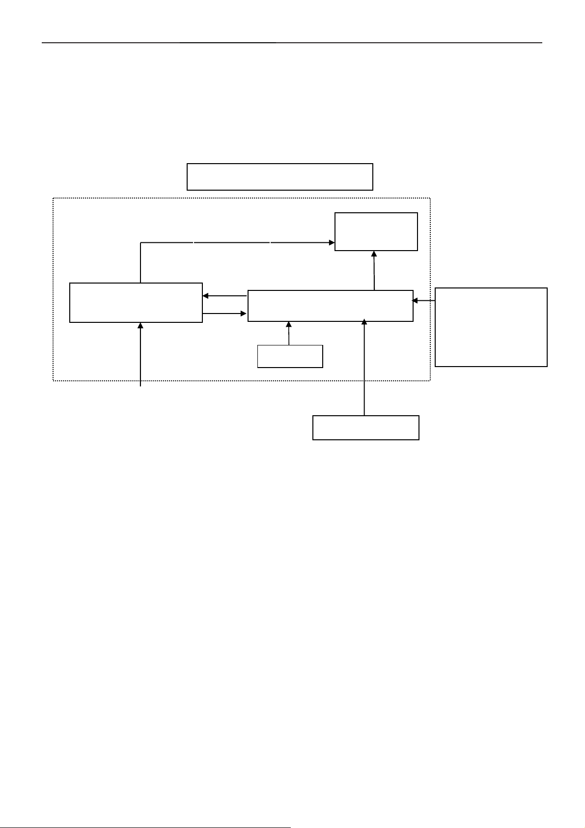
2. LCD Monitor Description
The LCD MONITOR will contain a main board, a power board, an audio board and a key board which house the flat
panel control logic, brightness control logic and DDC.
The power board will provide AC to DC Inverter voltage to drive the backlight of panel and the main board chips
each voltage.
PWPC board
(Include: adapter, inverter)
AC-IN
100V-240V
Monitor Block
CCFL Drive.
Main Board
Keyboard
Flat Panel and
CCFL backlight
RS232 Connector
For white balance
adjustment in factory
mode
Video signal DDC
HOST Computer
4
Page 5
19" LCD Color Monitor AOC 197P+
3. Operating Instructions
3.1 General Instructions
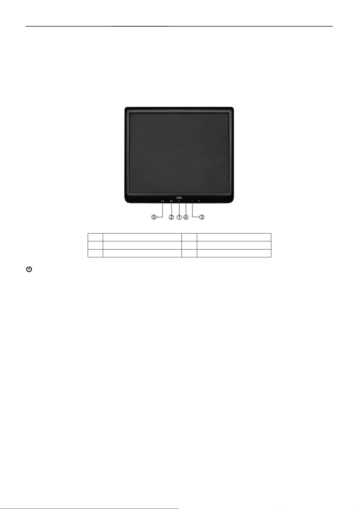
Press the power button to turn the monitor on or off. The other control buttons are located at front panel of the
monitor.
By changing these settings, the picture can be adjusted to your personal preferences.
The power cord should be connected.
-
Connect the video cable from the monitor to the video card.
-
Press the power button to turn on the monitor, the power indicator will light up.
-
3.2 Control Buttons
1 Power Button & Indicator 4 - / Brightness
2 Menu / Enter 5 Auto config / Exit
3 + / Contrast
/Power Button & Indicator:
Press this button to turn the monitor ON or OFF, And display the monitor’s state.
- Power Indicator:
- Green — Full Power Mode
- Orange — Active-off Mode
- MENU / ENTER :
Activate OSD menu when OSD is OFF or activate/de-activate adjustment function when OSD is ON or Exit OSD
menu when in Volume Adjust OSD status.
- +/ Contrast:
Activates the volume control when the OSD is OFF or navigate through adjustment icons when OSD is ON or
adjust a function when function is activated.
- - / Brightness:
Activates the volume control when the OSD is OFF or navigate through adjustment icons when OSD is ON or
adjust a function when function is activated.
- Auto config / Exit:
1. When OSD menu is in active status, this button will act as EXIT-KEY (EXIT OSD menu).
2. When OSD menu is in off status, press this button for 2 seconds to activate the Auto Adjustment function.
The Auto Adjustment function is used to set the HPos, VPos, Clock and Focus.
5
Page 6
19" LCD Color Monitor AOC 197P+
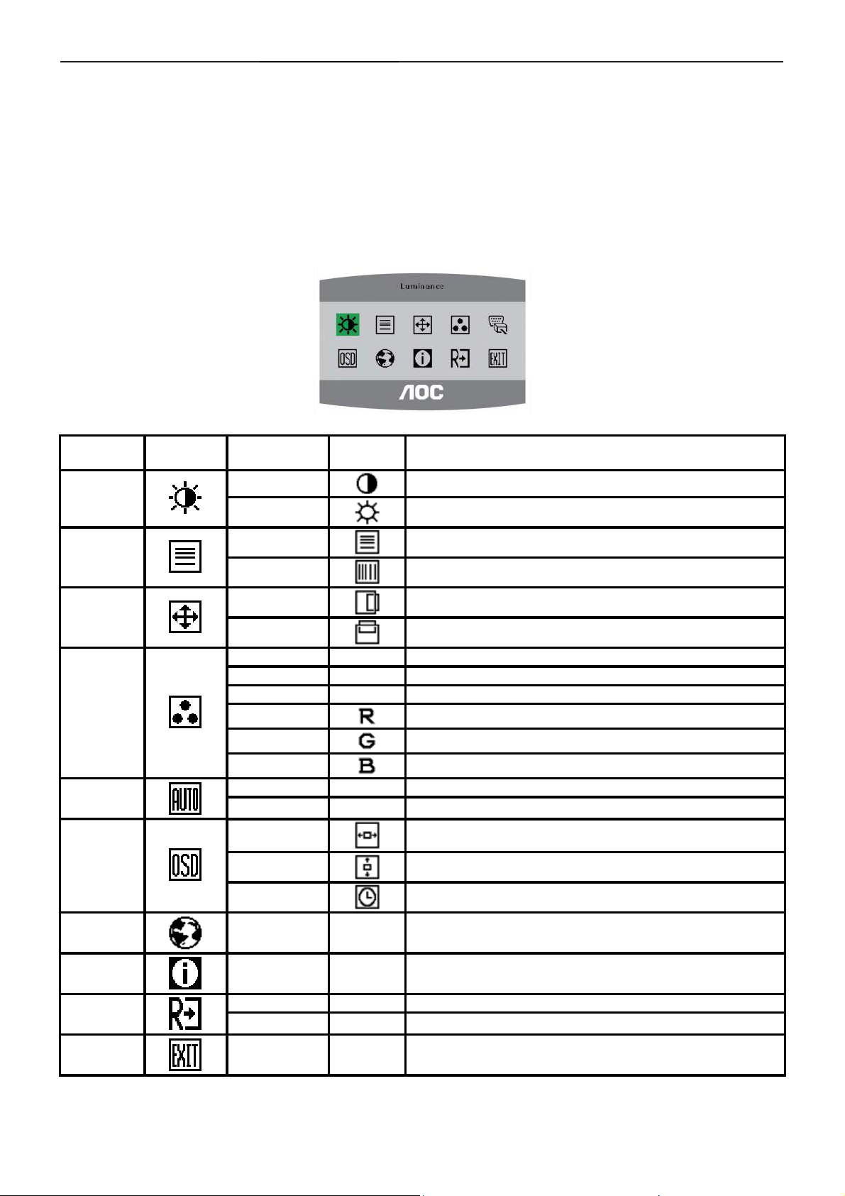
3.3 Adjusting the Picture
· Press the MENU-button to activate the OSD window.
· Press+ or - to navigate through the functions. Once the desired function is highlighted, press the MENU-button
to activate it. If the function selected has a sub-menu, · press or again to navigate through the sub-menu functions.
Once the desired function is highlighted, press MENU-button to activate it.
· Press+ or - to change the settings of the selected function. To exit and save, select the exit function. If you want
to adjust any other function, repeat steps 2-3.
· OSD Lock Function: To lock the OSD, press and hold the MENU button while the monitor is off and then press
power button to turn the monitor on. To un-lock the OSD - press and hold the MENU button while the monitor is off
and then press power button to turn the monitor on.
Main Menu
Item
Luminance
Image Setup
Image
Position
Color Temp.
Auto
Adjustment
OSD Setup
Main Menu
Icon
Sub Menu
Item
Contrast
Brightness
Focus
Clock
H. Position
V. Position
Warm N/A Recall Warm Color Temperature from EEPROM.
Cool N/A Recall Cool Color Temperature from EEPROM.
sRGB N/A Recall sRGB Temperature from EEPROM.
User / Red
User / Green
User / Blue
Yes N/A Auto adjusting H/V position, focus, phase.
No N/A Back to main OSD.
H. Position
V. Position
OSD Timeout
Sub Menu
Icon
Description
Contrast from Digital-register.
Backlight Adjustment
Adjust Picture Phase to reduce Horizontal-Line noise
Adjust picture Clock to reduce Vertical-Line noise.
Adjust the horizontal position of the picture.
Adjust the vertical position of the picture.
Red Gain from Digital-register.
Green Gain Digital-register.
Blue Gain from Digital-register.
Adjust the horizontal position of the OSD.
Adjust the vertical position of the OSD.
Adjust the OSD timeout.
Language
Information
Reset
Exit
Language N/A Set OSD language.
Information N/A
Yes N/A Clear each old status of Auto-configuration .
No N/A Do not execute reset, return to main menu.
N/A N/A Exit OSD
Show the resolution, H/V frequency and input port of current
input timing.
6
Page 7
19" LCD Color Monitor AOC 197P+
4. Input/Output Specification
4.1 Input Signal Connector
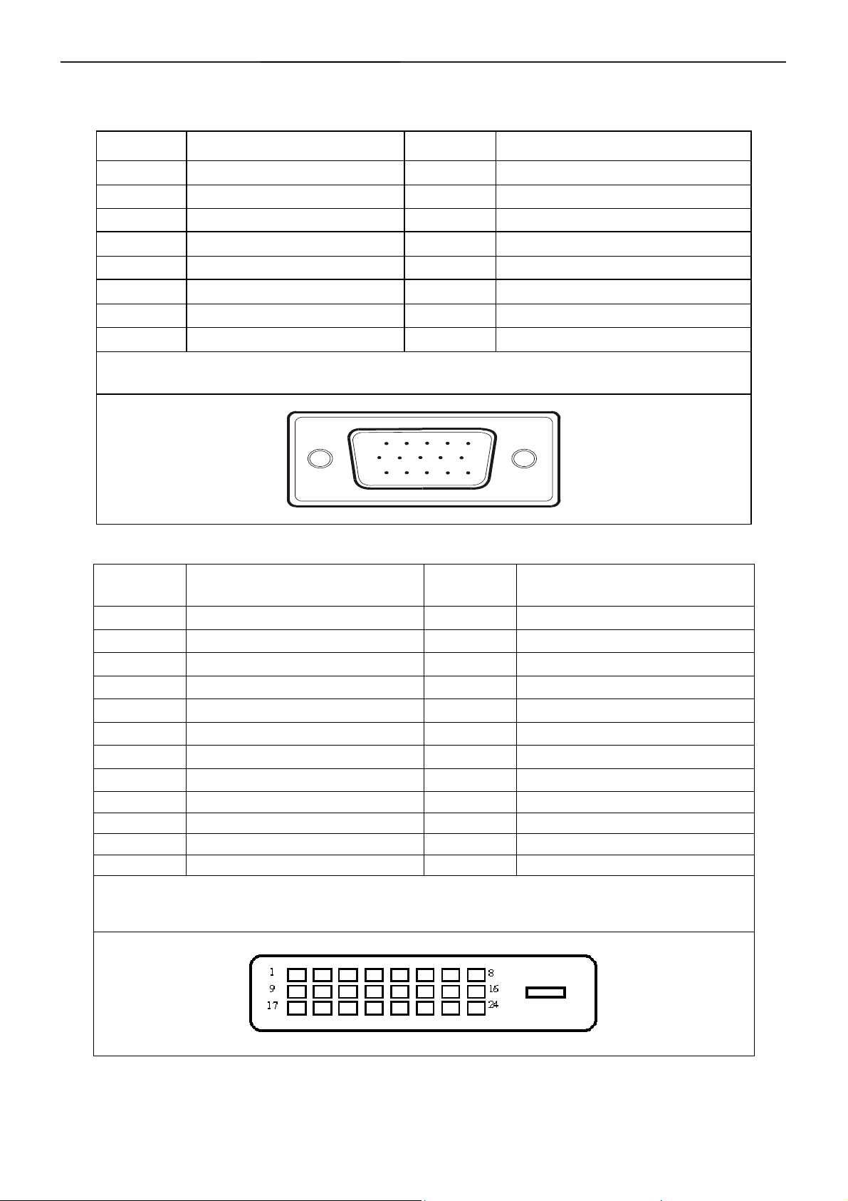
4.1.1 D-SUB connector
PIN NO. DESCRIPTION PI N NO. DESCRIPTION
1 Video-Red 9 +5V
2 Video-Green 10 Detect Cable
3 Video-Blue 11 Ground
4 GND 12 DDC-Serial data
5 DDC-Return 13 H-sync
6 GND-R 14 V-sync
7 GND-G 15 DDC-Serial clock
8 GND-B
VGA connector layout
15
6
11 15
10
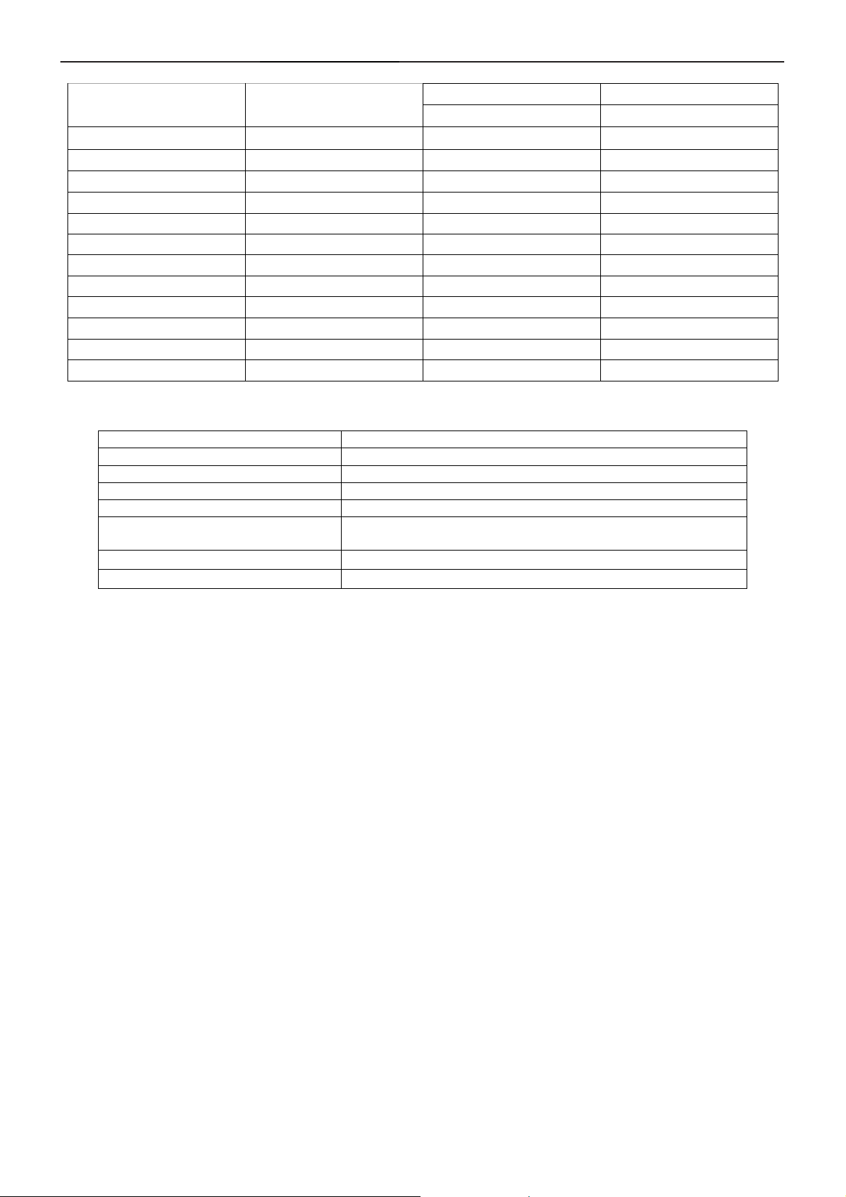
4.1.2 DVI-D connector
Pin No.
1 TMDS Data 2- 13 TMDS Data 3+
2 TMDS Data 2+ 14 +5V Power
3 TMDS Data 2/4 Shield 15 Ground(for+5V)
4 TMDS Data 4- 16 Hot Plug Detect
5 TMDS Data 4+ 17 TMDS Data 06 DDC Clock 18 TMDS Data 0+
7 DDC Data 19 TMDS Data 0/5 Shield
8 N.C. 20 TMDS Data 5-
9 TMDS Data 1- 21 TMDS Data 5+
10 TMDS Data 1+ 22 TMDS Clock Shield
11 TMDS Data 1/3 Shield 23 TMDS Clock +
12 TMDS Data 3- 24 TMDS Clock -
Signal Name
24 - Pin Color Display Signal Cable
Pin No.
Signal Name
7
Page 8
19" LCD Color Monitor AOC 197P+
4.2 Factory Preset Display Modes
Standard
Dos-mode 720 x 400
VGA 640 x 480
VGA 640 x 480 37.5 75
SVGA 800 x 600 37.879 60
SVGA 800 x 600 46.875 75
XGA 1024 x 768 48.363 60
XGA 1024 x 768 56.476 70
XGA 1024 x 768 60.02 75
XGA 1024 x 768 48.78 60
XGA 1024 x 768 60.241 75
SXGA 1280 x 1024 64 60
SXGA 1280 x 1024 80 75
Resolution
4.3 Power Supply Requirements
A/C Line voltage range 100 V ~ 240 V
A/C Line frequency range
Current 1.5A max at 100V; 0.8A max at 240 V
Peak surge current < 55A peak at 240 VAC and cold starting
Leakage current < 3.5mA
Power line surge
DC output Volt age
CURRENT
50 ± 3Hz, 60 ± 3Hz
No advance effects (no loss of information or defect)
with a maximum of 1 half-wave missing per second
5VDC ± 5%; 12VDC± 5%
1.5Amp (5V) ;2 Amp (12V)
Horizontal Vertical
Frequency (kHz) Frequency (Hz)
31.47 70
31.47 60
8
Page 9
19" LCD Color Monitor AOC 197P+
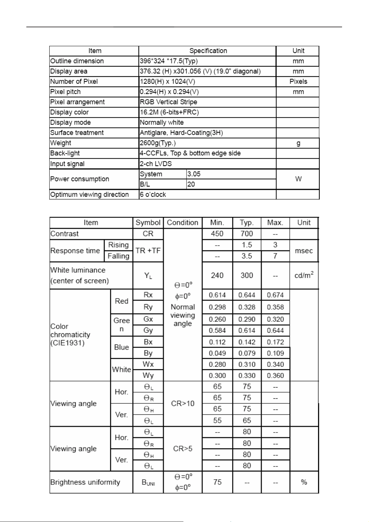
5 Panel Specification
5.1 Display Characteristics
5.2 Optical Characteristics
9
Page 10
19" LCD Color Monitor AOC 197P+
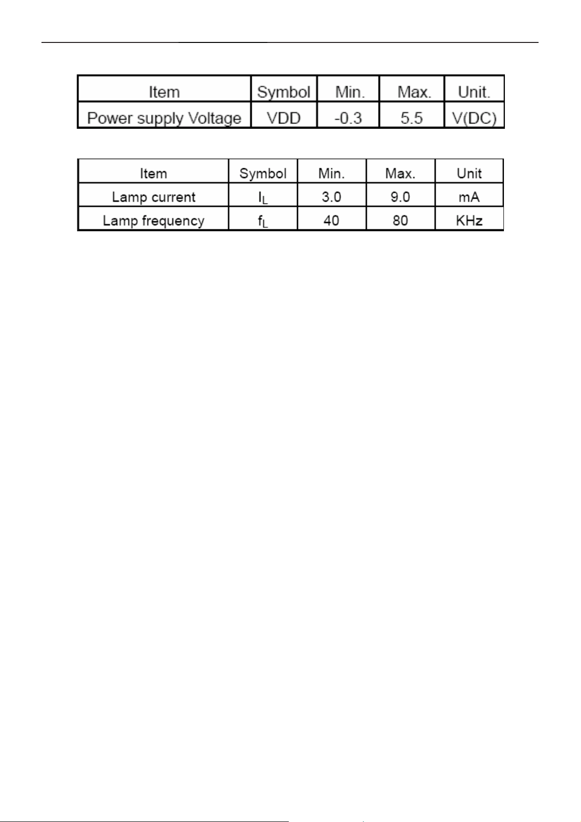
5.3 Parameter guide line for CCFL Inverter
1.TFT LCD Module:
2.Back Light Unit:
10
Page 11
19" LCD Color Monitor AOC 197P+
6. Block Diagram
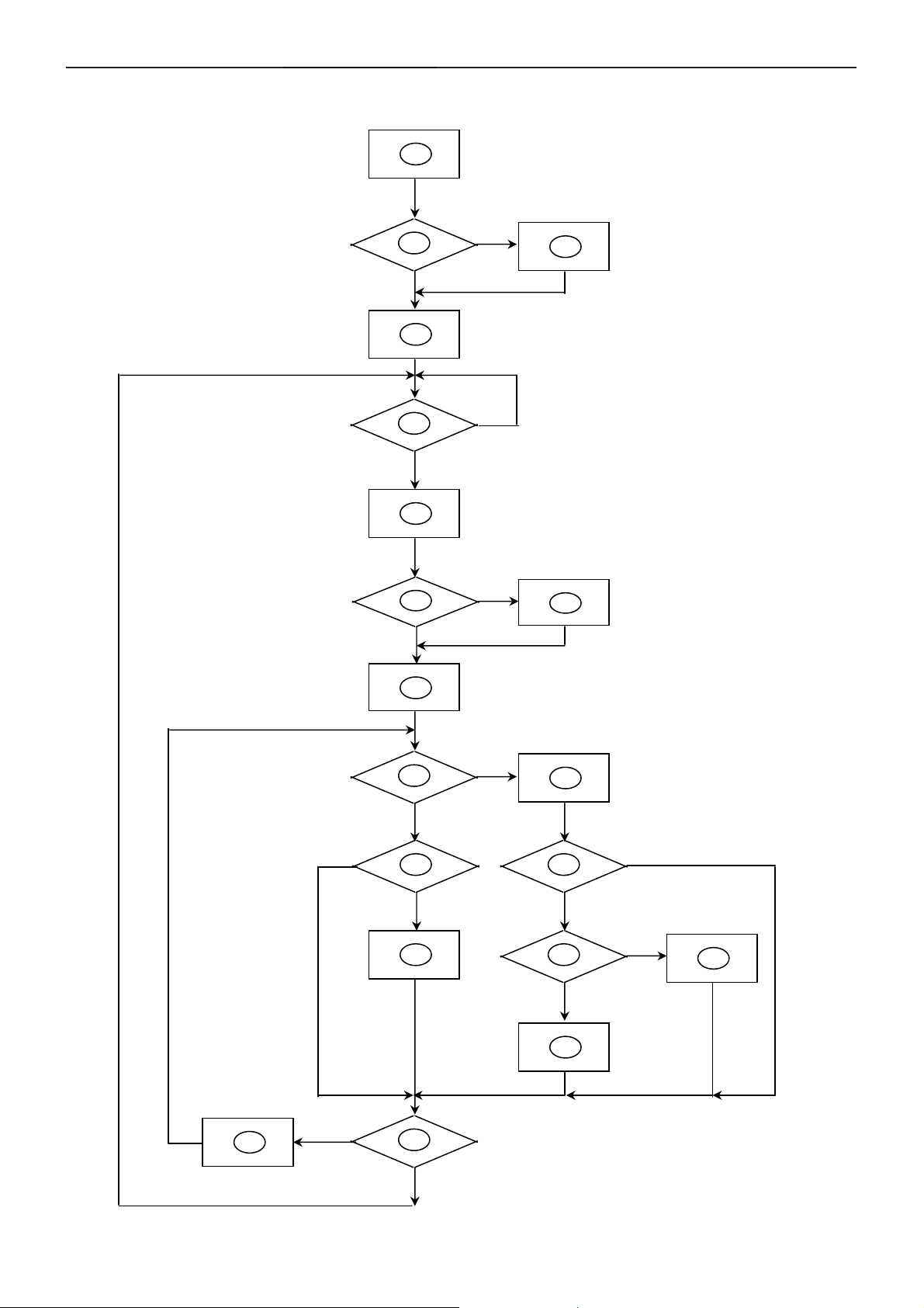
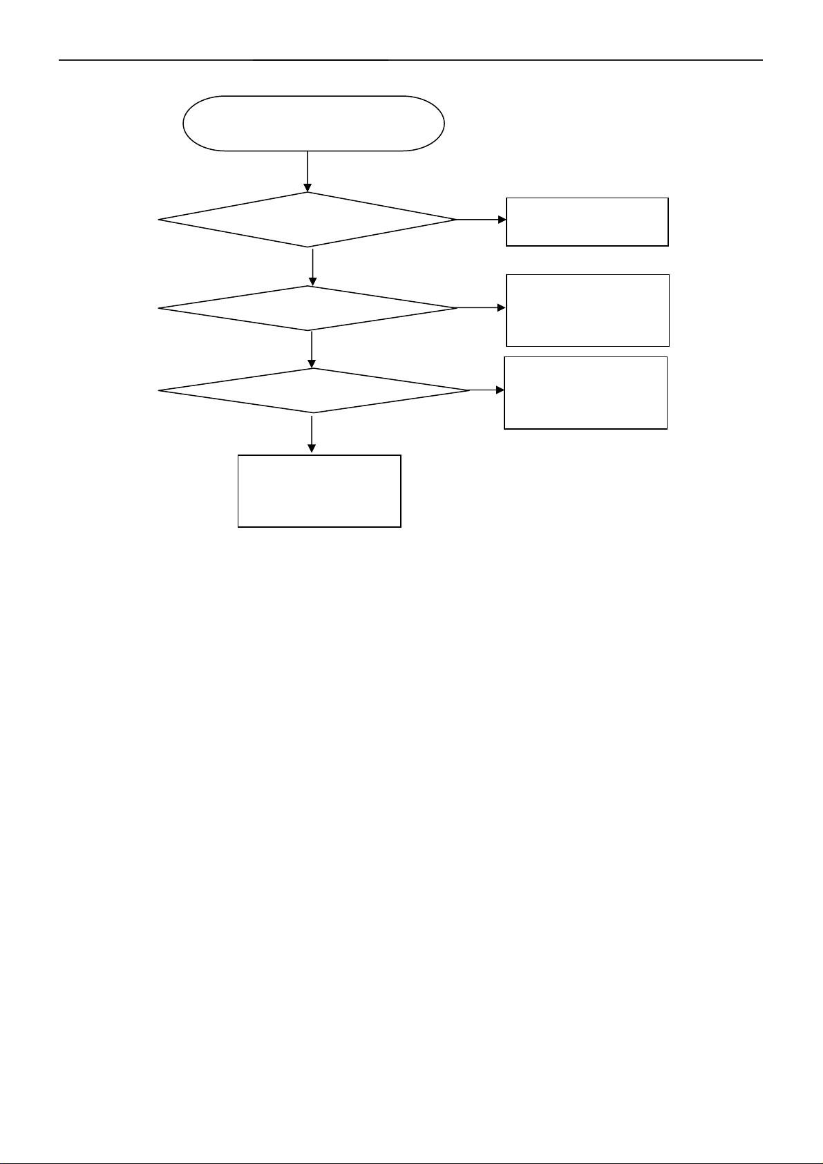
6.1 Software Flow Chat
1
2
N
4
5
Y
6
7
Y
N
N
3
18
9
10
Y
N
N
12
Y
14
19
N
11
13
15
17
N
Y
N
Y
16
Y
11
Page 12

19" LCD Color Monitor AOC 197P+
1) MCU initialize.
2) Is the EPROM blank?
3) Program the EPROM by default values.
4) Get the PWM value of brightness from EPROM.
5) Is the power key pressed?
6) Clear all global flags.
7) Are the AUT O and SELECT keys pressed?
8) Enter factory mode.
9) Save the power key status into EPROM.
Turn on the LED and set it to green color.
Scalar initializes.
10) In standby mode?
11) Update the lifetime of back light.
12) Check the analog port, are there any signals coming?
13) Does the scalar send out an interrupt request?
14) Wake up the scalar.
15) Are there any signals coming from analog port?
16) Display "No connection Check Signal Cable" message. And go into standby mode after the message
disappear.
17) Program the scalar to be able to show the coming mode.
18) Process the OSD display.
19) Read the keyboard. Is the power key pressed?
12
Page 13
19" LCD Color Monitor AOC 197P+
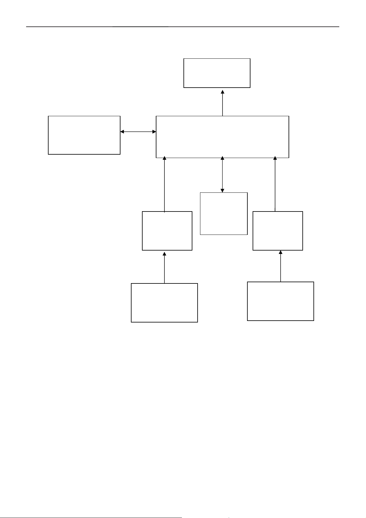
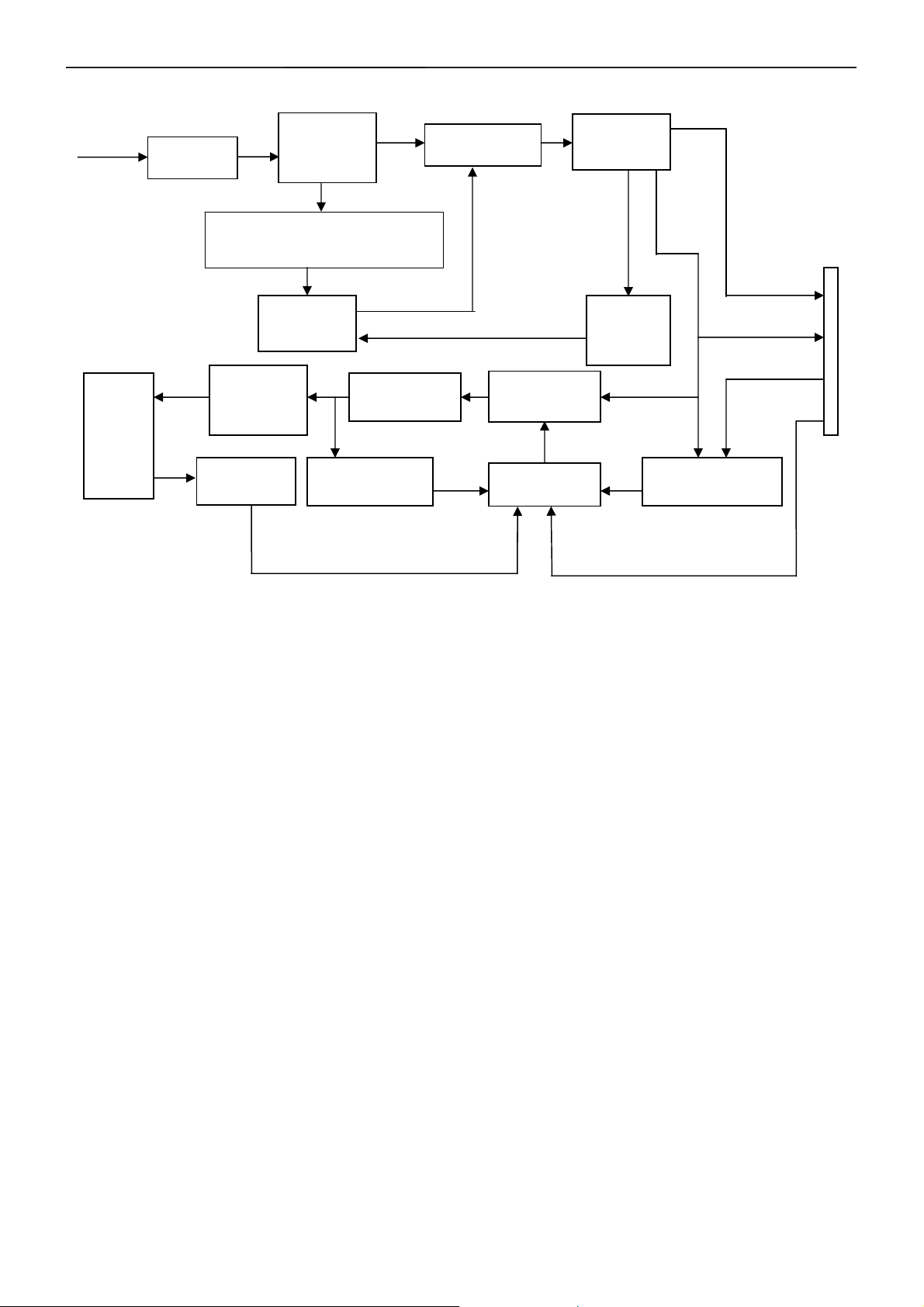
6.2 Electric Block Diagram
6.2.1 Main Board
FLASH MEMORY
PM25LV512
(U402)
H sync
V sync
RGB
D-Sub
Connector
(CN405)
LCD Interface
(CN101)
Scalar TSUMO56J
(Include: MCU, ADC, OSD etc)
(U401)
RGB
EEPROM
24LC16B
(U403)
DCLK+
DCLK-
DVID
Connector
(CN406)
EEPROM
M24C02
(U404)
EEPROM
M24C02
(U405)
13
Page 14
19" LCD Color Monitor AOC 197P+
6.2.2 Inverter / Power Board
AC input
EMI filter
Start Circuit: R905、R906、
R907、R908、R909、R910
Lamp
OSC and
Output
Circuit
Feedback
Circuit
Bridge
Rectifier
and Filter
PWM
Control IC
DC Convert
Circuit
Over Voltage
Protect
Transformer
PWM
Control IC
Rectifier
diode
MOSFET
PWM
Over
Voltage
Protect
12V
ON/OFF
ON/OFF Control
DIM
5V
14
Page 15
19" LCD Color Monitor AOC 197P+
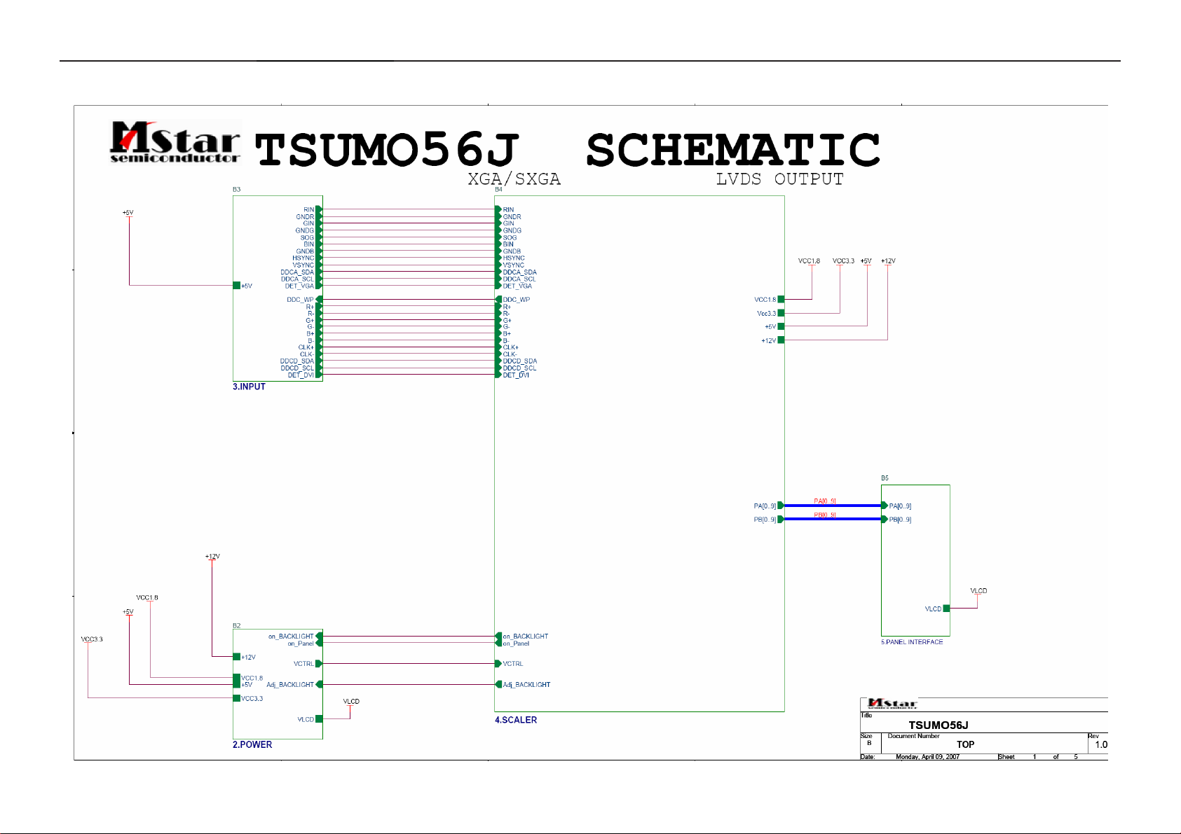
7. Schematic
7.1 Main Board
15
Page 16

19" LCD Color Monitor AOC 197P+
16
Page 17

19" LCD Color Monitor AOC 197P+
17
Page 18

19" LCD Color Monitor AOC 197P+
18
Page 19

19" LCD Color Monitor AOC 197P+
19
Page 20

19" LCD Color Monitor AOC 197P+
7.2 Power Board
1
+
BD901
2A 800V
3
R900
330K 1/8W
2
-
4
2
3
L902
L
1
4
2
3
L901
L
1
4
C909 0.47uF/250V
R901
330K 1/8W
R902
330K 1/8W
3
12
CN901
SOCKET
C902
0.001uF/ 250V
C901
0.001uF/ 250V
12
t
T2.5A/250V
F901
NR901
5 ohm/8A
1
2
0.1uF/50V
GND1
1
GND
HS3 D920
HEAT SIN K
+
C912
C907
100uF/450V
IC901
LD7575
R911
100K 1/10W
1
GND
C916
0.1uF/50V
7
穝
470PF/25V
GND2
1
2
HEAT SINK
8
HV
LD7575
N.C
RT1CS
C914
HS4 Q900
R905
10K 1/8W
OUT
GND
COMP
4
2
T901
4
C905
0.0033uF/250V
C900
0.0022uF/250V
IC902
PC123FY 2 4P
O
2
O
1
43
IC921
KIA431
O
O
R909
100K 2W
C910
1500pF/1KV
D901
UF4003PT
+
C911
D910
LL4148WP
R912
10 1/8W
10K 1/10W
R913
1K 1/10W
C915
22uF/50V
R915
D911
NC
NC
N.C ZD901
RLZ27B
1 2
6
VCC
5
3
C913
220pF/50V
D900
BA159GPT
R910
7R5 1/8W
Q900
FQPF8N60C
1
3 2
R916
0.43 2W
Q910
1
NC
3 2
12
11
10
86
7
9
12
R954
47 1/8W
R955
47 1/8W
R956
47 1/8W
R951
R952
47 1/8W
R953
47 1/8W
47 1/8W
3
1
3
1
D922
3A/60V
C920
0.001uF/ 500V
D920
SBT150-10LS
2
2
N.C D921
FMW-2156
C921
0.001uF/ 500V
R922
470 1/4W
R925
1K 1/10W
C928
0.1uF/50V
R928
1K 1/4W
ZD921
RLZ13B
1 2
D915
R927
100 1/10W
+
C922
680uF/25V
+
1000uF/16V
LL4148WP
蔼跋
19mm,ㄏノ13x16size
L921
+
C923
+
C924
680uF/25V
680uF/25V
C926
+
C932
470uF/16V
ZD922
RLZ5.1B
1 2
D916
LL4148WP
R923
10K 1/10W
C929
0.1uF/ 50V
R930
100 1/10W
RJ901
0 1/8W
3.5UH
L922
R924
3.6K 1/10W 1%
R929
2.4K 1/10W 1%
+
470UF/25V
3.5UH
C925
+
C927
470UF/16V
R926
33K 1/10W 1%
RJ902
0 1/8W
R931
10K 1/8W
CN902
CONNECTOR
F902
0 1/8W
1
2
3
4
5
6
7
8
9
10
J901
TIN COATED
+12V
ZD920
TPSMP9 1A-E3 DO-220AA
1 2
F903
0 1/8W
ON/OFF
+5V
C931
0.1uF/50V
C930
0.1uF/50V
AOC (Top Victory) Electronics Co., Ltd.
Title
Size Document Number Rev
Custom
Date: Sheet
audio 12V
DIM
PWPC1742HDE2P(715G1823-1)
Monday, May 29, 2006
+5V
J902
TIN COATED
J903
TIN COATED
J904
TIN COATED
J905
TIN COATED
J906
TIN COATED
J907
TIN COATED
J908
TIN COATED
J909
TIN COATED
J910
TIN COATED
J911
TIN COATED
11
of
A
20
Page 21

19" LCD Color Monitor AOC 197P+
RJ801
0 1/8W
+12V
ON/OFF
AOC (Top Victory) Electronics Co., Ltd.
Title
Size Doc um ent N um ber Rev
Date: Sheet
R803
10K 1/10W
N.C R806
470 1/8W
+5V
N.C R838
0 1/8W
DIM
R808
470K 1/8W
C803
0.01UF/50V
J811
TIN COATED
J812
TIN COATED
J818
TIN COATED
J823
TIN COATED
2. FOR 17" 4 LAMPS INVERTER
PWPC1742HDE1
Monday, May 29, 2006
300K 1/8W
PMBS3904
J814
TIN COATED
J819
TIN COATED
RJ802
0 1/8W
R802
Q801
1
N.C C801
0.1uF/50V
R811
150K 1/10W
1
32
C804
2.2uF/25V
J815
TIN COATED
J820
TIN COATED
R812
10K 1/10W
RJ803
R804
10K 1/8W
R809
1M 1/10W
J816
TIN COATED
J821
TIN COATED
of
ZD801
RLZ5.6B
RJ804
0 1/8W
PMBS3904
C805
1000PF/50V
A
0 1/10W
32
Q802
PMBS3904
11
R805
470 1/8W
Q803
1
R810
R813
1M 1/10W
J817
TIN COATED
J822
TIN COATED
穝糤箂ン
C811
470UF/25V
32
VCC
R807
22 1/8W
100K 1/10W
R814
56K 1/10W
C820
470UF/25V
C828,C829
+
C806
1UF/25V
+
N.C C828
0.1uF/50V
AM9945
10 1/10W
Q805
R842
N.C C829
0.1uF/50V
R818
15 1/8W
C812
N.C R839
1500PF/50V
33K 1/8W
8
6
D1N7D1N
S1N1G1N2S2P3G2P
IC801
1
DRV1
2
VDDA
3
TIMER
4
DIM
5
ISEN
6
VSEN
7
OVPT
NC18NC2
OZ9938
R828
C822
N.C R840
1500PF/50V
33K 1/8W
1000P/50V
D2P5D2P
4
PGND
DRV2
GNDA
CT
SSTCMP
LCT
ENA
15 1/8W
8
S1N1G1N2S2P3G2P
N.C C814
16
15
14
13
12
11
10
9
N.C C815
1000P/50V
6
D1N7D1N
R819
15 1/8W
C813
1500PF/50V
R837
10 1/10W
R829
C823
D2P5D2P
4
15 1/8W
1500PF/50V
Q806
AM9945
PT801
80GL17T-36-DN
5
3
4
1 8
15K 1/10W
C830
100PF/50V
1
R815
R816
100K 1/10W
C808
C807
0.01UF/50V
80GL19T-36-DN
5
3
4
1 8
C832
7
R820
2
D801
BAV70
3
R817
1M 1/10W
C809
6800PF/50V
PT802
R830
15K 1/10W
100PF/50V
1
3
36K 1/10W 1%
0.047UF/50V
D803
BAV70
7
2
C816
10PF/3KV
R821
100K 1/10W
C831
N.C R 844 39K 1/ 10W
C810
560PF/50V
C825
10PF/3KV
R831
100K 1/10W
C817
3PF/3KV
R822
3M / 1/2W
C818
270PF/50V
R827
3.6K 1/10W 1%
R841
R826
C819
0.022UF/ 25V
300 1/10W 1%
390 1/10W 1%
100PF/50V
N.C R823
75K 1/10W
1Mohm brust frequency:400HZ
C826
3PF/3KV
C827
270PF/50V
C833
100PF/50V
N.C R833
75K 1/10W
R832
3M / 1/2W
R834
3.6K 1/10W 1%
R836
1K 1/10W
2
3
1
D802
BAV99
R825
560 1/10W
17" R841 =390ohm
19" R841 = 300ohm
R843
1K 1/10W
3
D804
BAV99
R835
560 1/10W
2
1
C835
1UF/25V
C837
1UF/25V
1UF/25V
C838
C836
1UF/25V
CN801
2
1
33G8021-2D-U
CN802
2
1
33G8021-2D-U
CN803
1
2
33G8021-2D-U
CN804
1
2
33G8021-2D-U
21
Page 22

19" LCD Color Monitor AOC 197P+
8. PCB Layout
8.1 Main Board
22
Page 23

19" LCD Color Monitor AOC 197P+
23
Page 24

19" LCD Color Monitor AOC 197P+
24
Page 25

19" LCD Color Monitor AOC 197P+
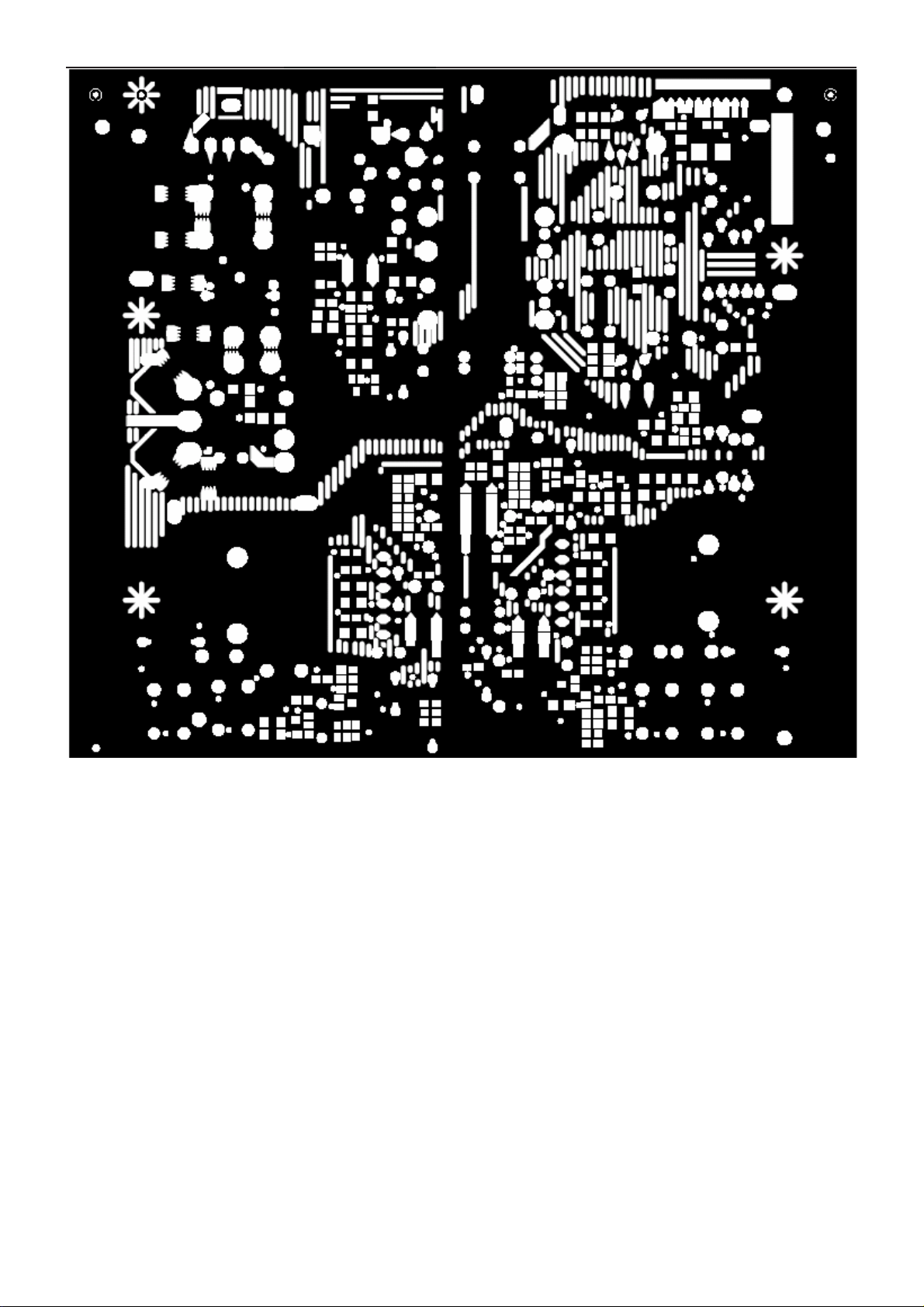
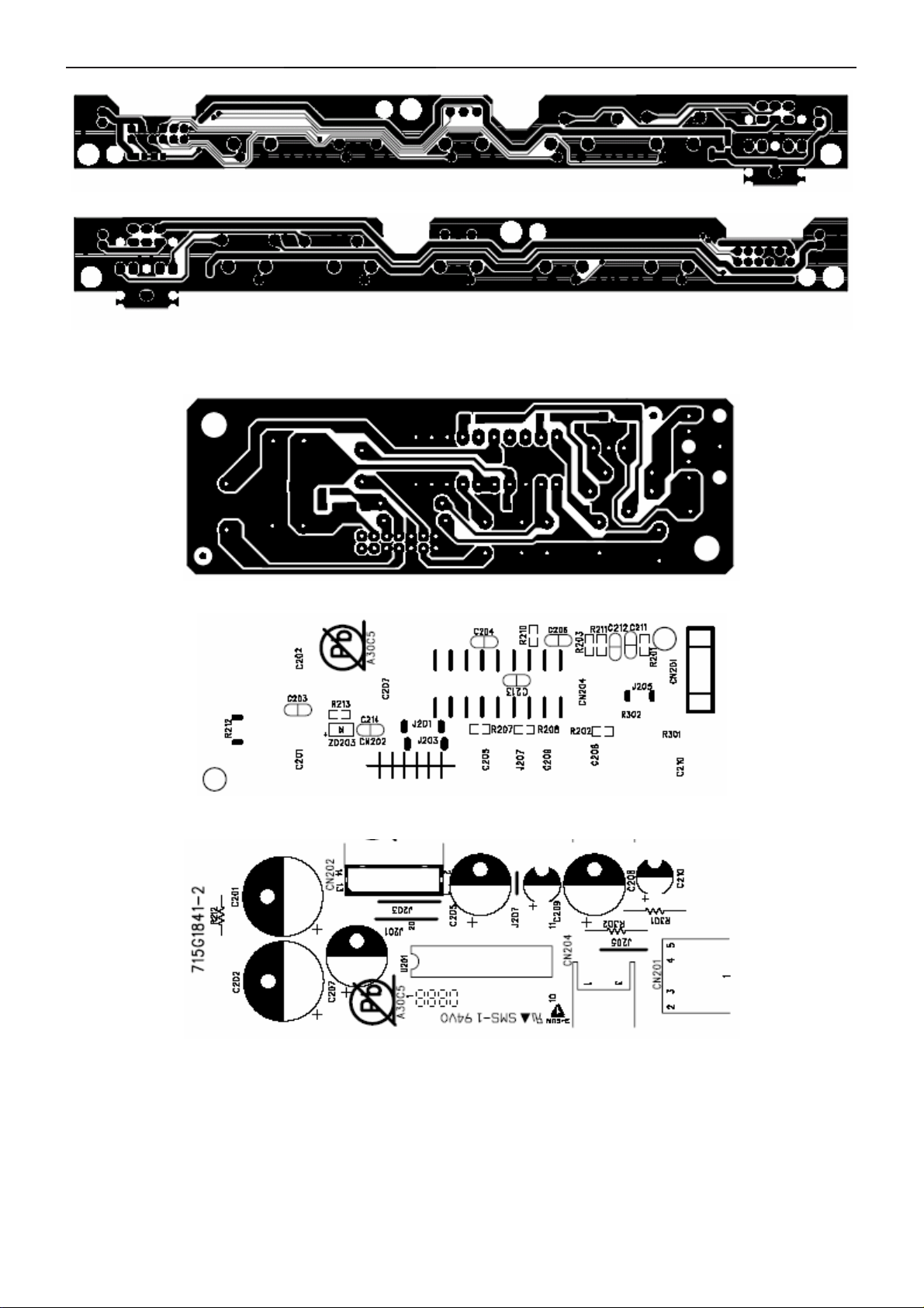
8.2 Power Board
25
Page 26
19" LCD Color Monitor AOC 197P+
26
Page 27

19" LCD Color Monitor AOC 197P+
27
Page 28
19" LCD Color Monitor AOC 197P+
8.3 Key Board
8.4 Audio Board
28
Page 29

19" LCD Color Monitor AOC 197P+
9. Maintainability
9.1 Equipments and Tools Requirement
1. Voltmeter.
2. Oscilloscope.
3. Pattern Generator.
4. DDC Tool with an IBM Compatible Computer.
5. Alignment Tool.
6. LCD Color Analyzer.
7. Service Manual.
8. User Manual.
29
Page 30

19" LCD Color Monitor AOC 197P+
9.2 Trouble Shooting
9.2.1 Main Board
1. NO SCREEN APPEAR
No power
Press power key and look
if the picture is normal
Please reinsert and make sure
the AC of 100-240 is no rmal
Measure U702 PIN2=3.3V
X401 oscillate waveforms
are normal
No power
OK
OK
OK
NG
NG
NG
NG
Replace X401
Reinsert or check the
power section
Measure CN701 PIN5/6=12V?
Measure CN701 PIN9/10=5V?
OK
Replace U702
NG
Check power
section
Replace U401
30
Page 31

19" LCD Color Monitor AOC 197P+
No picture (LED orange)
Measure U401 PIN28=3.3V
Check if the sync signal from computer
is output and video cable is connected
normally
No picture
OK
X401 oscillate waveforms are
normal
OK
OK
Replace U401
NG
NG
NG
Replace U401
Replace X401
Input the sync signal of
computer, or change the
cable
31
Page 32

19" LCD Color Monitor AOC 197P+
9.2.2 Power Board
1. No Power
Check CN902 pin3= 12V
NG
Check AC lin e volt 110V or 220V
OK
NG
Check AC input
Check the voltage of C907(+)
OK
NG
Check bridge rectified circuit and F901 circuit
Check start voltage for the pin3 of IC901
OK
NG
Check R912,R913 and Change IC901
Check the auxiliary voltage is bigger than
10V and smaller than 20V
OK
NG
1) Check IC901
2) Check OVP circuit
Check IC901 pin8 PWM wave
OK
NG
Check IC901
Check Q900,R910,T901,D900,D901
32
Page 33

19" LCD Color Monitor AOC 197P+
2. W/LED No Backlight
Check C811 (+) =12V
NG OK
Change Q803
Check ON/OFF signal
OK
NG
Check main board
Check IC801 pin6=12V
OK
NG
Change Q805 or Q806
Check the pin1 of IC801 have saw tooth wave
Change IC801
Check D801/D802/D803/D804 have the output of square wave at
OK
NG
Check R820/R821/C817/R822
Check R830/R831/C826/R832
Check the resonant wave of pin2 & pin5 for PT801/PT802
OK
Check the output of PT801/PT802
NG
Check R819/C813/R818/C812
Check R828/C822/R829/C823
OK
NG
Check connecter & lamp
Change PT801/PT802
33
Page 34
19" LCD Color Monitor AOC 197P+
9.2.3 Key Board
OSD is unstable or not working
Is Key Pad Board connecting normally ?
Y
Is Button Switch normally ?
Y
N
N
Connect Key Pad Board
Replace Button Switch
Is Key Pad Board normally ?
N
Replace Key Pad Board
Y
Check Main Board
34
Page 35
19" LCD Color Monitor AOC 197P+
10. White- Balance, Luminance Adjustment
Approximately 30 minutes should be allowed for warm up before proceeding White-Balance adju stment.
1. How to do the Chroma-7120 MEM. Channel setting
A. Reference to chroma 7120 user guide
B. Use “ SC” key and “ NEXT” key to modify x, y, Y value and use “ID” key to modify the
TEXT description Following is the procedure to do white-balance adjust
2. Setting the color temp. you want
A. MEM.CHANNEL 3 (7800 color):
7800 color temp. parameter is x = 296 ±20, y = 311 ±20, Y = 180 cd/m
B. MEM.CHANNEL 4 (6500 color):
6500 color temp. parameter is x = 313±20, y = 329 ±20, Y =180 cd/m2
3. Into factory mode of 197P+
Turn on power, press the MENU button, pull out the power cord, and then plug the power cord. Then the fact ory
OSD will be at the left top of the panel.
4. Bias adjustment:
2 ,
Set the Contrast
to 50; Adjust the Brightness to 90.
5. Gain adjustment:
Move cursor to “-F-” and press MENU key
A. Adjust C2 (7800) color-temperature
1. Switch the Chroma-7120 to RGB-Mode (with press “MODE” button)
2. Switch the MEM. Channel to Channel 3 (with up or down arrow on chroma 7120)
2
3. The LCD-indicator on chroma 7120 will show x = 296 ±20, y = 311 ±20, Y =180 cd/m
4. Adjust the RED of color1 on factory window until chroma 7120 indicator reached the value R=100
5. Adjust the GREEN of color1 on factory window until chroma 7120 indicator reached the value G=100
6. Adjust the BLUE of color1 on factory window until chroma 7120 indicator reached the value B=100
7. Repeat above procedure (item 4,5,6) until chroma 7120 RGB value meet the tolerance =100±5
B. Adjust C1 (6500) color-temperature
1. Switch the chroma-7120 to RGB-Mode (with press “MODE” button)
2. Switch the MEM.channel to Channel 4(with up or down arrow on chroma 7120)
2
3. The LCD-indicator on chroma 7120 will show x = 313 ±20, y = 329 ±20, Y = 180 cd/m
4. Adjust the RED of color3 on factory window until chroma 7120 indicator reached the value R=100
5. Adjust the GREEN of color3 on factory window until chroma 7120 indicator reached the value G=100
6. Adjust the BLUE of color3 on factory window until chroma 7120 indicator reached the value B=100
7. Repeat above procedure (item 4,5,6) until chroma 7120 RGB value meet the tolerance =100±5
C. Turn the Power-button off to quit from factory mode.
35
Page 36

19" LCD Color Monitor AOC 197P+
11. Monitor Exploded View
36
Page 37

19" LCD Color Monitor AOC 197P+
12. BOM List
T97HM8HLF1MGAE
Location Part NO. Description
AUPC980KH6AP AUDIO BOARD
CBPC986KH8AOP MAIN BOARD
KEPC980KH6AP KEY BOARD
PWPC942HE1P POWER BOARD
15G5786 1 BKT VESA
26G 800504 3H BARCODE
40G 58162435A MANUAL LABEL
41G 68615 4B TCO'99 CARD
50G 600 2 HANDLE1
50G 600 3 HANDLE2
52G 1185 MIDDLE TAPE
52G 1186 SMALL TAPE
52G6020 5 PROTECT FILM
78G 322 1A KL SPK 8OHM 1.5W KUAIDA
78G 322 1A KR SPK 8OHM 1.5W KUAIDA
89G 17356G553 AUDIO CABLE
E089A 89G 715HAA D2 SIGNAL CABLE
89G1745CAA 9 SIGNAL CABLE
89G412A15NIS3 POWER CORD
95G8014 16E02 KEY HARNESS
95G8018 30695 LVDS
M1G 130 5120 SCREW M3X5
M1G 330 4128 CR3 SCREW M3X4
M1G 330 6 47 CR3 SCREW 3X6mm
M1G1140 6128 CR3 SCREW
M1G1730 6128 CR3 SCREW M3x6
M1G1730 6128 CR3 SCREW M3x6
M1G2640 10225 CR3 SCREW
P1G1730 8128 CR3 SCREW M3x8
Q1G 330 8 47 CR3 SCREW 3X8mm
Q1G 330 8128 CR3 SCREW 3X8mm
Q1G1030 6128 CR3 SCREW
705GQ9K0P34002 19" LCD BASE-STAND ASS'
E750L 750GLH9013D12N PANEL 190ME13-D10 2 HSD
H40G 19N61528A ID LABEL
H40G 58161547B AOC LOGO LABEL
H41G780061511A WARRANTY CARD
H44G3965615 3A CARTON
H45G 87 1 6 R PE BAG FOR MONITOR
H45G 87 4 3 R PE BAG FOR BASE
H45G 87 4 H R PE BAG FOR BASE
H52G6025 16 18 INSULATE SHEET
H70G200761520A CD MANUAL
Q15G8313 1 AC SOCKET BRACKET
Q15G8342 N 1 MAIN FRAME
Q33G4985 GM 1L KEY BUTTON
Q33G4986 1 1C POWER LENS
Q34G1871 GM AB REAR COVER
Q34G1872 GMB1B BEZEL
Q41G7800615B31 QSG
Q44G3965 3EPE EPE(L)
Q44G3965 4EPE EPE(R)
Q44G3965 5 U TYPE SHEET
37
Page 38

19" LCD Color Monitor AOC 197P+
Q45G 88606 14 R PE BAG
Q45G 88621 29 R PE RING
Q52G6025 11999 INSULATE SHEET
Q85G 740 2 1 SHIELD
CN202 33G802414C H 2*7PIN DUAL ROW RIGHT A
CN201 88G 30210K PHONE JACK
U201 Q90G6093 2 HEAT SINK
U201 56G 616 1 TDA7496L BY ST
R207 61G0603102 RST CHIPR 1KOHM +-5% 1/
R208 61G0603102 RST CHIPR 1KOHM +-5% 1/
R210 61G0603203 RST CHIPR 20KOHM +-5% 1
R211 61G0603203 RST CHIPR 20KOHM +-5% 1
R202 61G0603204 RST CHIPR 200KOHM +-5%
C211 65G0805103 32 10NF/50V/0805/X7R
C212 65G0805103 32 10NF/50V/0805/X7R
C203 65G0805104 32 CHIP 0.1U 50V X7R
C213 65G0805104 32 CHIP 0.1U 50V X7R
C204 65G0805474 22 CHIP 0.47UF 25V X7R 080
C206 65G0805474 22 CHIP 0.47UF 25V X7R 080
715G1841 2 AUDIO BOARD PCB
J201 95G 90 23 TINCOATEDCOPPER
J203 95G 90 23 TINCOATEDCOPPER
J205 95G 90 23 TINCOATEDCOPPER
J207 95G 90 23 TINCOATEDCOPPER
R301 61G 60218352T RST CFR 18KOHM +-5% 1/6
R302 61G 60218352T RST CFR 18KOHM +-5% 1/6
R212 61G 60222452T RST CFR 220KOHM +-5% 1/
C209 67G 2151007NT ELCAP 10UF +-20% 50V 10
C210 67G 2151007NT ELCAP 10UF +-20% 50V 10
C201 67G215B4713HT ELCAP 470UF +-20% 16V 1
C202 67G215B4713HT ELCAP 470UF +-20% 16V 1
C205 67G215B4713HT ELCAP 470UF +-20% 16V 1
C207 67G215B4713HT ELCAP 470UF +-20% 16V 1
C208 67G215B4713HT ELCAP 470UF +-20% 16V 1
CN404 33G801714A BH PIN HEADER 2*7 R/A
CN701 33G8027 12 WAFER 2*6P 2.0MM R/A
CN403 33G8027 16 WAFER 16PIN 2.0mm DIP
CN101 33G8027 24 CONN W TO B 12P*2 P*2.0
40G 457624 1B CPU LABEL
40G 45762412B CBPC LABEL
44G3231508512 GASKET
C707 67G215V101 4N ELCAP 100UF +-20% 25V 1
C710 67G215V101 4N ELCAP 100UF +-20% 25V 1
C712 67G215V101 4N ELCAP 100UF +-20% 25V 1
C717 67G215V101 4N ELCAP 100UF +-20% 25V 1
C408 67G305V100 3P ELCAP 10UF +-20% 16V 10
C418 67G305V100 3P ELCAP 10UF +-20% 16V 10
C403 67G305V479 3P ELCAP 4.7UF +-20% 16V 1
C702 67G305V479 3P ELCAP 4.7UF +-20% 16V 1
CN405 88G 35315F H D-SUB 15PIN
CN406 88G 35424F H DVID CONN. 24P FEMALE
U401 90G6250 1 GP HEAT SINK
X401 93G 22 53 14.31818MHZ HC-49US
U401 56G 562130 TSUMO56J-LF PQFP-128
U702 56G 563 7 AIC1084-33PM
U404 56G1133 34 M24C02-WMN6TP
38
Page 39

19" LCD Color Monitor AOC 197P+
U405 56G1133 34 M24C02-WMN6TP
U402 56G1133 63 PM25LV010-25SCE
U403 56G113356A 24LC16B/SNG SOIC-8PIN
Q402 57G 417 4 PMBS3904/PHILIPS-SMT(04
Q406 57G 417 4 PMBS3904/PHILIPS-SMT(04
Q701 57G 417 4 PMBS3904/PHILIPS-SMT(04
Q703 57G 417 4 PMBS3904/PHILIPS-SMT(04
Q706 57G 417 4 PMBS3904/PHILIPS-SMT(04
Q401 57G 417 6 PMBS3906/PHILIPS-SMT(06
Q403 57G 417 6 PMBS3906/PHILIPS-SMT(06
Q405 57G 417 6 PMBS3906/PHILIPS-SMT(06
Q702 57G 417 17 T PZT2907A
Q704 57G 763 1 AO3401L SOT23 BY AOS(A1
FB410 61G0603000 RST CHIPR 0 OHM +-5% 1/
FB411 61G0603000 RST CHIPR 0 OHM +-5% 1/
FB412 61G0603000 RST CHIPR 0 OHM +-5% 1/
R412 61G0603000 RST CHIPR 0 OHM +-5% 1/
R419 61G0603000 RST CHIPR 0 OHM +-5% 1/
R421 61G0603000 RST CHIPR 0 OHM +-5% 1/
R431 61G0603000 RST CHIPR 0 OHM +-5% 1/
R432 61G0603000 RST CHIPR 0 OHM +-5% 1/
R705 61G0603000 RST CHIPR 0 OHM +-5% 1/
R721 61G0603000 RST CHIPR 0 OHM +-5% 1/
R462 61G0603100 RST CHIPR 10 OHM +-5% 1
R463 61G0603100 RST CHIPR 10 OHM +-5% 1
R464 61G0603100 RST CHIPR 10 OHM +-5% 1
R465 61G0603100 RST CHIPR 10 OHM +-5% 1
R466 61G0603100 RST CHIPR 10 OHM +-5% 1
R467 61G0603100 RST CHIPR 10 OHM +-5% 1
R468 61G0603100 RST CHIPR 10 OHM +-5% 1
R469 61G0603100 RST CHIPR 10 OHM +-5% 1
R476 61G0603100 1F RST CHIPR 1KOHM +-1% 1/
R477 61G0603100 1F RST CHIPR 1KOHM +-1% 1/
R478 61G0603100 1F RST CHIPR 1KOHM +-1% 1/
R479 61G0603100 1F RST CHIPR 1KOHM +-1% 1/
R411 61G0603101 RST CHIPR 100 OHM +-5%
R418 61G0603101 RST CHIPR 100 OHM +-5%
R420 61G0603101 RST CHIPR 100 OHM +-5%
R427 61G0603101 RST CHIPR 100 OHM +-5%
R428 61G0603101 RST CHIPR 100 OHM +-5%
R429 61G0603101 RST CHIPR 100 OHM +-5%
R434 61G0603101 RST CHIPR 100 OHM +-5%
R435 61G0603101 RST CHIPR 100 OHM +-5%
R436 61G0603101 RST CHIPR 100 OHM +-5%
R441 61G0603101 RST CHIPR 100 OHM +-5%
R442 61G0603101 RST CHIPR 100 OHM +-5%
R443 61G0603101 RST CHIPR 100 OHM +-5%
R445 61G0603101 RST CHIPR 100 OHM +-5%
R453 61G0603101 RST CHIPR 100 OHM +-5%
R454 61G0603101 RST CHIPR 100 OHM +-5%
R455 61G0603101 RST CHIPR 100 OHM +-5%
R456 61G0603101 RST CHIPR 100 OHM +-5%
R458 61G0603101 RST CHIPR 100 OHM +-5%
R488 61G0603101 RST CHIPR 100 OHM +-5%
R701 61G0603101 RST CHIPR 100 OHM +-5%
R704 61G0603101 RST CHIPR 100 OHM +-5%
39
Page 40

19" LCD Color Monitor AOC 197P+
R410 61G0603102 RST CHIPR 1KOHM +-5% 1/
R446 61G0603102 RST CHIPR 1KOHM +-5% 1/
R447 61G0603102 RST CHIPR 1KOHM +-5% 1/
R470 61G0603102 RST CHIPR 1KOHM +-5% 1/
R404 61G0603103 RST CHIPR 10KOHM +-5% 1
R406 61G0603103 RST CHIPR 10KOHM +-5% 1
R408 61G0603103 RST CHIPR 10KOHM +-5% 1
R413 61G0603103 RST CHIPR 10KOHM +-5% 1
R415 61G0603103 RST CHIPR 10KOHM +-5% 1
R424 61G0603103 RST CHIPR 10KOHM +-5% 1
R425 61G0603103 RST CHIPR 10KOHM +-5% 1
R426 61G0603103 RST CHIPR 10KOHM +-5% 1
R444 61G0603103 RST CHIPR 10KOHM +-5% 1
R450 61G0603103 RST CHIPR 10KOHM +-5% 1
R451 61G0603103 RST CHIPR 10KOHM +-5% 1
R452 61G0603103 RST CHIPR 10KOHM +-5% 1
R457 61G0603103 RST CHIPR 10KOHM +-5% 1
R459 61G0603103 RST CHIPR 10KOHM +-5% 1
R460 61G0603103 RST CHIPR 10KOHM +-5% 1
R461 61G0603103 RST CHIPR 10KOHM +-5% 1
R471 61G0603103 RST CHIPR 10KOHM +-5% 1
R485 61G0603103 RST CHIPR 10KOHM +-5% 1
R487 61G0603103 RST CHIPR 10KOHM +-5% 1
R489 61G0603103 RST CHIPR 10KOHM +-5% 1
R490 61G0603103 RST CHIPR 10KOHM +-5% 1
R708 61G0603103 RST CHIPR 10KOHM +-5% 1
R711 61G0603103 RST CHIPR 10KOHM +-5% 1
R714 61G0603103 RST CHIPR 10KOHM +-5% 1
R717 61G0603103 RST CHIPR 10KOHM +-5% 1
R723 61G0603103 RST CHIPR 10KOHM +-5% 1
R727 61G0603103 RST CHIPR 10KOHM +-5% 1
R409 61G0603121 RST CHIPR 120 OHM +-5%
R414 61G0603121 RST CHIPR 120 OHM +-5%
R480 61G0603150 1F RST CHIPR 1.5KOHM +-1%
R703 61G0603202 RST CHIPR 2KOHM +-5% 1/
R448 61G0603222 RST CHIPR 2.2KOHM +-5%
R449 61G0603222 RST CHIPR 2.2KOHM +-5%
R405 61G0603223 RST CHIPR 22KOHM +-5% 1
R403 61G0603390 0F RST CHIPR 390 OHM +-1%
R474 61G0603392 RST CHIPR 3.9KOHM +-5%
R475 61G0603392 RST CHIPR 3.9KOHM +-5%
R401 61G0603470 RST CHIPR 47 OHM +-5% 1
R402 61G0603470 RST CHIPR 47 OHM +-5% 1
R437 61G0603471 RST CHIPR 470 OHM +-5%
R416 61G0603472 RST CHIPR 4.7KOHM +-5%
R422 61G0603472 RST CHIPR 4.7KOHM +-5%
R423 61G0603472 RST CHIPR 4.7KOHM +-5%
R491 61G0603472 RST CHIPR 4.7KOHM +-5%
R707 61G0603472 RST CHIPR 4.7KOHM +-5%
R712 61G0603472 RST CHIPR 4.7KOHM +-5%
R725 61G0603472 RST CHIPR 4.7KOHM +-5%
R702 61G0603510 RST CHIPR 51 OHM +-5% 1
R438 61G0603750 RST CHIPR 75 OHM +-5% 1
R439 61G0603750 RST CHIPR 75 OHM +-5% 1
R440 61G0603750 RST CHIPR 75 OHM +-5% 1
FB401 61G0805000 RST CHIPR 0 OHM +-5% 1/
40
Page 41

19" LCD Color Monitor AOC 197P+
FB404 61G0805000 RST CHIPR 0 OHM +-5% 1/
C421 65G0603100 31 CHIP 10PF+-0.5PF 50V NP
C423 65G0603100 31 CHIP 10PF+-0.5PF 50V NP
C435 65G0603102 32 1000PF +-10% 50V X7R
C401 65G0603104 32 CHIP 0.1UF 50V X7R
C402 65G0603104 32 CHIP 0.1UF 50V X7R
C404 65G0603104 32 CHIP 0.1UF 50V X7R
C405 65G0603104 32 CHIP 0.1UF 50V X7R
C406 65G0603104 32 CHIP 0.1UF 50V X7R
C407 65G0603104 32 CHIP 0.1UF 50V X7R
C409 65G0603104 32 CHIP 0.1UF 50V X7R
C410 65G0603104 32 CHIP 0.1UF 50V X7R
C411 65G0603104 32 CHIP 0.1UF 50V X7R
C412 65G0603104 32 CHIP 0.1UF 50V X7R
C413 65G0603104 32 CHIP 0.1UF 50V X7R
C414 65G0603104 32 CHIP 0.1UF 50V X7R
C415 65G0603104 32 CHIP 0.1UF 50V X7R
C416 65G0603104 32 CHIP 0.1UF 50V X7R
C419 65G0603104 32 CHIP 0.1UF 50V X7R
C420 65G0603104 32 CHIP 0.1UF 50V X7R
C422 65G0603104 32 CHIP 0.1UF 50V X7R
C426 65G0603104 32 CHIP 0.1UF 50V X7R
C427 65G0603104 32 CHIP 0.1UF 50V X7R
C428 65G0603104 32 CHIP 0.1UF 50V X7R
C429 65G0603104 32 CHIP 0.1UF 50V X7R
C430 65G0603104 32 CHIP 0.1UF 50V X7R
C445 65G0603104 32 CHIP 0.1UF 50V X7R
C447 65G0603104 32 CHIP 0.1UF 50V X7R
C448 65G0603104 32 CHIP 0.1UF 50V X7R
C449 65G0603104 32 CHIP 0.1UF 50V X7R
C450 65G0603104 32 CHIP 0.1UF 50V X7R
C451 65G0603104 32 CHIP 0.1UF 50V X7R
C452 65G0603104 32 CHIP 0.1UF 50V X7R
C453 65G0603104 32 CHIP 0.1UF 50V X7R
C454 65G0603104 32 CHIP 0.1UF 50V X7R
C455 65G0603104 32 CHIP 0.1UF 50V X7R
C456 65G0603104 32 CHIP 0.1UF 50V X7R
C706 65G0603104 32 CHIP 0.1UF 50V X7R
C709 65G0603104 32 CHIP 0.1UF 50V X7R
C711 65G0603104 32 CHIP 0.1UF 50V X7R
C713 65G0603104 32 CHIP 0.1UF 50V X7R
C714 65G0603104 32 CHIP 0.1UF 50V X7R
C718 65G0603104 32 CHIP 0.1UF 50V X7R
C715 65G0603105 12 CHIP 1UF 16VX7R 0603
C443 65G0603221 32 CHIP 220PF 50V X7R
C417 65G0603224 22 CHIP 0.22UF 25V X7R
C425 65G0603224 22 CHIP 0.22UF 25V X7R
C444 65G0603224 22 CHIP 0.22UF 25V X7R
C446 65G0603224 22 CHIP 0.22UF 25V X7R
C442 65G0603330 31 33PF+-5% 50V NPO
C432 65G0603473 32 CHIP 0.047UF 50V X7R
C433 65G0603473 32 CHIP 0.047UF 50V X7R
C434 65G0603473 32 CHIP 0.047UF 50V X7R
C436 65G0603473 32 CHIP 0.047UF 50V X7R
C437 65G0603473 32 CHIP 0.047UF 50V X7R
C438 65G0603473 32 CHIP 0.047UF 50V X7R
41
Page 42

19" LCD Color Monitor AOC 197P+
C439 65G0603473 32 CHIP 0.047UF 50V X7R
C440 65G0603473 32 CHIP 0.047UF 50V X7R
C441 65G0603473 32 CHIP 0.047UF 50V X7R
FB408 71G 56G301 EA
FB407 71G 56K121 M CHIP BEAD
FB402 71G 56Z601 CHIP BEAD 600 OHM 0805
FB403 71G 56Z601 CHIP BEAD 600 OHM 0805
FB405 71G 56Z601 CHIP BEAD 600 OHM 0805
FB409 71G 59B121 TB160808B
D406 93G 39149 MLL5232B BY FULL POWER
D408 93G 39149 MLL5232B BY FULL POWER
D409 93G 39149 MLL5232B BY FULL POWER
D410 93G 39149 MLL5232B BY FULL POWER
D411 93G 39149 MLL5232B BY FULL POWER
D412 93G 39149 MLL5232B BY FULL POWER
D414 93G 39149 MLL5232B BY FULL POWER
D415 93G 39149 MLL5232B BY FULL POWER
D416 93G 39149 MLL5232B BY FULL POWER
D426 93G 39149 MLL5232B BY FULL POWER
D407 93G 64 42 P BAV70 SOT-23
D413 93G 64 42 P BAV70 SOT-23
D702 93G 6432P LL4148
D403 93G 6433P BAV99
D404 93G 6433P BAV99
D405 93G 6433P BAV99
D417 93G 6433P BAV99
D418 93G 6433P BAV99
D419 93G 6433P BAV99
D420 93G 6433P BAV99
D421 93G 6433P BAV99
D422 93G 6433P BAV99
D423 93G 6433P BAV99
D424 93G 6433P BAV99
D401 93G 39S 45 T RLZ36B BY ROHM
D402 93G 39S 45 T RLZ36B BY ROHM
D425 93G 39S 45 T RLZ36B BY ROHM
D701 93G1020 1 S GS1D
D704 93G2040 3F FA20-04
715G2069 2 MAIN BOARD PCB
CN003 33G3802 2 WAFER 2.0MM 2P
CN004 33G3802 2 WAFER 2.0MM 2P
CN001 33G8027 12 WAFER 2*6P 2.0MM R/A
SW001 77G 602 1 CJ TACT SWITCH TSVB-2
SW002 77G 602 1 CJ TACT SWITCH TSVB-2
SW003 77G 602 1 CJ TACT SWITCH TSVB-2
SW004 77G 602 1 CJ TACT SWITCH TSVB-2
SW005 77G 602 1 CJ TACT SWITCH TSVB-2
DP001 81G 12 1F GP LED
CN002 88G 30217T TO PHONE JACK+SWITCH
R001 61G 60251152T RST CFR 510 OHM +-5% 1/
R002 61G 60251152T RST CFR 510 OHM +-5% 1/
R003 61G0603000 RST CHIPR 0 OHM +-5% 1/
C01 65G0603101 31 CHIP 100PF 50V NPO
C02 65G0603101 31 CHIP 100PF 50V NPO
FB01 71G 59B121 TB160808B
FB02 71G 59B121 TB160808B
BEAD 300 欧
42
Page 43
19" LCD Color Monitor AOC 197P+
715G1819 1 KEY BOARD PCB
CN801 33G8021 2E U WAFER
CN802 33G8021 2E U WAFER
CN803 33G8021 2E U WAFER
CN804 33G8021 2E U WAFER
40G 45762420A ID LABEL
IC902 56G 139 3A PC123Y22FZOF
NR901 61G 58080 WT RST NTCR 8 OHM
R916 61G152M438 64 RST MOFR 0.43 OHM +-5%
C909 63G107K474 HS X2 CAP 0.47UF K 275VAC
C816 65G 3J1206ET H 12PF 5% SL 3KV TDK
C825 65G 3J1206ET H 12PF 5% SL 3KV TDK
C817 65G 3J3096ET H 3PF,J,3KV,Z5P
C826 65G 3J3096ET H 3PF,J,3KV,Z5P
C900 65G306M2222BP 2200PF +-20% 400VAC
C905 65G306M3322BP 3300PF 20%
C907 67G315Z10115H ELCAP 100UF +-20% 450V
L902 73G 174 64 H LINE FILTER
L901 73G 174 76 L CHOKE COIL LI TAI LF-00
L921 73G 253 91 S CHOKE COIL
L922 73G 253 91 S CHOKE COIL
T901 80GL17T 33 N POWER X'FMR
PT801 80GL17T 36 DN XFMR FOR POWER DARFON
PT802 80GL17T 36 DN XFMR FOR POWER DARFON
CN901 87G 501 32 S AC SOCKET
CN902 95G8014 12 42 HARNESS
705G 909 11 06 R909 ASS'Y
705G 920 06 14 D920 ASS'Y
705G D90 11 06 D900 ASS'Y
705GJ9K0 57002 Q900 ASS'Y
Q51G 6 4508 RTV
HS6 Q85G0043 1 S SHIELD
C901 65G305M1022E2 1000P 400VAC/250VAC
C902 65G305M1022E2 1000P 400VAC/250VAC
C926 67G215L1023HS ELCAP 1000UF +-20% 16V
C927 67G215L4713HL ELCAP 470UF +-20% 16V 1
C932 67G215L4713HL ELCAP 470UF +-20% 16V 1
C811 67G215Y471 4H ELCAP 470UF +-20% 25V 1
C820 67G215Y471 4H ELCAP 470UF +-20% 25V 1
C925 67G215Y471 4H ELCAP 470UF +-20% 25V 1
C922 67G215Y681 4H ELCAP 680UF +-20% 25V 1
C923 67G215Y681 4H ELCAP 680UF +-20% 25V 1
C924 67G215Y681 4H ELCAP 680UF +-20% 25V 1
BD901 93G 50460502 KBP206G
D922 93G3006 1 31DQ06FC
IC901 56G 379 61 LD7575PS SOP-8
IC801 56G 608 10 OZ9938GN
Q801 57G 417 4 PMBS3904/PHILIPS-SMT(04
Q802 57G 417 4 PMBS3904/PHILIPS-SMT(04
Q803 57G 417 4 PMBS3904/PHILIPS-SMT(04
Q805 57G 763 14 AM9945N
Q806 57G 763 14 AM9945N
R837 61G0805100 RST CHIPR 10 OHM +-5% 1
R842 61G0805100 RST CHIPR 10 OHM +-5% 1
R821 61G0805100 3F RST CHIPR 100KOHM +-1%
R831 61G0805100 3F RST CHIPR 100KOHM +-1%
43
Page 44

19" LCD Color Monitor AOC 197P+
R911 61G0805100 3F RST CHIPR 100KOHM +-1%
R927 61G0805101 RST CHIPR 100 OHM +-5%
R930 61G0805101 RST CHIPR 100 OHM +-5%
R836 61G0805102 RST CHIPR 1KOHM +-5% 1/
R843 61G0805102 RST CHIPR 1KOHM +-5% 1/
R913 61G0805102 RST CHIPR 1KOHM +-5% 1/
R925 61G0805102 RST CHIPR 1KOHM +-5% 1/
R928 61G0805102 RST CHIPR 1KOHM +-5% 1/
R803 61G0805103 RST CHIPR 10KOHM +-5% 1
R812 61G0805103 RST CHIPR 10KOHM +-5% 1
R915 61G0805103 RST CHIPR 10KOHM +-5% 1
R923 61G0805103 RST CHIPR 10KOHM +-5% 1
R810 61G0805104 RST CHIPR 100KOHM +-5%
R815 61G0805104 RST CHIPR 100KOHM +-5%
R813 61G0805105 RST CHIPR 1MOHM +-5% 1/
R816 61G0805105 RST CHIPR 1MOHM +-5% 1/
R820 61G0805150 2F RST CHIPR 15KOHM +-1% 1
R830 61G0805150 2F RST CHIPR 15KOHM +-1% 1
R929 61G0805240 1F RST CHIPR 2.4KOHM +-1%
R817 61G0805330 2F RST CHIPR 33KOHM +-1% 1
R926 61G0805330 2F RST CHIPR 33KOHM +-1% 1
R841 61G0805360 0F RST CHIPR 360 OHM +-1%
R827 61G0805360 1F RST CHIPR 3.6KOHM +-1%
R834 61G0805360 1F RST CHIPR 3.6KOHM +-1%
R924 61G0805360 1F RST CHIPR 3.6KOHM +-1%
R826 61G0805391 RST CHIPR 390 OHM +-5%
C808 61G0805394 RST CHIPR 390KOHM +-5%
R811 61G0805514 RST CHIPR 510KOHM +-5%
R825 61G0805561 RST CHIPR 560 OHM +-5%
R835 61G0805561 RST CHIPR 560 OHM +-5%
R814 61G0805623 RST CHIPR 62KOHM +-5% 1
C835 61G1206000 RST CHIPR 0 OHM +-5% 1/
C836 61G1206000 RST CHIPR 0 OHM +-5% 1/
C837 61G1206000 RST CHIPR 0 OHM +-5% 1/
C838 61G1206000 RST CHIPR 0 OHM +-5% 1/
F902 61G1206000 RST CHIPR 0 OHM +-5% 1/
F903 61G1206000 RST CHIPR 0 OHM +-5% 1/
RJ801 61G1206000 RST CHIPR 0 OHM +-5% 1/
RJ901 61G1206000 RST CHIPR 0 OHM +-5% 1/
RJ902 61G1206000 RST CHIPR 0 OHM +-5% 1/
R912 61G1206100 RST CHIPR 10 OHM +-5% 1
R804 61G1206103 RST CHIPR 10KOHM +-5% 1
R808 61G1206103 RST CHIPR 10KOHM +-5% 1
R905 61G1206103 RST CHIPR 10KOHM +-5% 1
R931 61G1206103 RST CHIPR 10KOHM +-5% 1
R818 61G1206150 RST CHIPR 15 OHM +-5% 1
R819 61G1206150 RST CHIPR 15 OHM +-5% 1
R828 61G1206150 RST CHIPR 15 OHM +-5% 1
R829 61G1206150 RST CHIPR 15 OHM +-5% 1
R807 61G1206220 RST CHIPR 22 OHM +-5% 1
R802 61G1206304 RST CHIPR 300KOHM +-5%
R900 61G1206334 RST CHIPR 330KOHM +-5%
R901 61G1206334 RST CHIPR 330KOHM +-5%
R902 61G1206334 RST CHIPR 330KOHM +-5%
R951 61G1206470 RST CHIPR 47 OHM +-5% 1
R952 61G1206470 RST CHIPR 47 OHM +-5% 1
44
Page 45

19" LCD Color Monitor AOC 197P+
R954 61G1206470 RST CHIPR 47 OHM +-5% 1
R955 61G1206470 RST CHIPR 47 OHM +-5% 1
R805 61G1206471 RST CHIPR 470 OHM +-5%
R910 61G1206759 RST CHIPR 7.5 OHM +-5%
C833 65G0805101 31 CHIP 100PF 50V NPD 0805
C805 65G0805102 32 CHIP 1000P 50VX7R 0805
C807 65G0805103 32 10NF/50V/0805/X7R
C912 65G0805104 32 CHIP 0.1U 50V X7R
C916 65G0805104 32 CHIP 0.1U 50V X7R
C928 65G0805104 32 CHIP 0.1U 50V X7R
C929 65G0805104 32 CHIP 0.1U 50V X7R
C930 65G0805104 32 CHIP 0.1U 50V X7R
C931 65G0805104 32 CHIP 0.1U 50V X7R
C806 65G0805105 22 CHIP 1UF 25V X7R 0805
C812 65G0805152 32 CHIP 1500PF 50V X7R 080
C813 65G0805152 32 CHIP 1500PF 50V X7R 080
C822 65G0805152 32 CHIP 1500PF 50V X7R 080
C823 65G0805152 32 CHIP 1500PF 50V X7R 080
C913 65G0805221 32 CHIP 220PF 50V X7R 0805
C819 65G0805223 22 CHIP 0.022UF 25V X7R 08
C804 65G0805225 12 CHIP 2.2UF 15V X7R 0805
C818 65G0805271 31 MLCC 0805 270PF J 50V N
C827 65G0805271 31 MLCC 0805 270PF J 50V N
C831 65G0805271 31 MLCC 0805 270PF J 50V N
C830 65G0805470 31 47PF/50V/0805/NPO
C832 65G0805470 31 47PF/50V/0805/NPO
C914 65G0805471 22 470PF 25V
C809 65G0805473 32 CHIP 0.047UF 50V X7R
C810 65G0805561 31 CHIP 560PF 50V NPO 0805
D801 93G 64 42 P BAV70 SOT-23
D803 93G 64 42 PP BAV70 SOT-23
D910 93G 64 44 S LL4148WP
D915 93G 64 44 S LL4148WP
D916 93G 64 44 S LL4148WP
D802 93G 6433P BAV99
D804 93G 6433P BAV99
ZD801 93G 39S 24 T RLZ 5.6B LLDS
ZD922 93G 39S 25 T RLZ5.1B BY ROHM
ZD920 93G 39S 38 T PTZ 9.1B
ZD921 93G 39S 40 T RLZ 13B LLDS
CN901 6G 31500 EYELET
L901 6G 31502 1.5MM RIVET
L902 6G 31502 1.5MM RIVET
NR901 6G 31502 1.5MM RIVET
PT801 6G 31502 1.5MM RIVET
PT802 6G 31502 1.5MM RIVET
Q900 6G 31502 1.5MM RIVET
R916 6G 31502 1.5MM RIVET
T901 6G 31502 1.5MM RIVET
715G1823 3 POWER BOARD PCB
J811 95G 90 23 TINCOATEDCOPPER
J812 95G 90 23 TINCOATEDCOPPER
J814 95G 90 23 TINCOATEDCOPPER
J815 95G 90 23 TINCOATEDCOPPER
J816 95G 90 23 TINCOATEDCOPPER
J817 95G 90 23 TINCOATEDCOPPER
45
Page 46

19" LCD Color Monitor AOC 197P+
J818 95G 90 23 TINCOATEDCOPPER
J820 95G 90 23 TINCOATEDCOPPER
J821 95G 90 23 TINCOATEDCOPPER
J822 95G 90 23 TINCOATEDCOPPER
J823 95G 90 23 TINCOATEDCOPPER
J824 95G 90 23 TINCOATEDCOPPER
J825 95G 90 23 TINCOATEDCOPPER
J901 95G 90 23 TINCOATEDCOPPER
J902 95G 90 23 TINCOATEDCOPPER
J903 95G 90 23 TINCOATEDCOPPER
J904 95G 90 23 TINCOATEDCOPPER
J905 95G 90 23 TINCOATEDCOPPER
J906 95G 90 23 TINCOATEDCOPPER
J907 95G 90 23 TINCOATEDCOPPER
J908 95G 90 23 TINCOATEDCOPPER
J909 95G 90 23 TINCOATEDCOPPER
J910 95G 90 23 TINCOATEDCOPPER
R922 61G 17247152T RST CFR 470 0HM +-5% 1/
R822 61G212Y305 KT RST MGFR 3MOHM +-5% 1/2
R832 61G212Y305 KT RST MGFR 3MOHM +-5% 1/2
F901 84G 55 2 MET2.50
D901 93G1020 752T UF4003
IC921 56G 158 10 T AZ431AZ-AE1 TO-92
C910 65G 1K152 1T6052 1.5nF /1K Y5P+-10%
C920 65G517K102 5T 1000PF 10% Y5P 500V
C921 65G517K102 5T 1000PF 10% Y5P 500V
C911 67G 2152207RT ELCAP 22UF +-20% 50V 10
34FPE19P03 CASE EEL19
34FPE19P03 CASE EEL19
R909 61G152M10458F6W56 RST MOFR 100KOHM +-5% 2
96G 29 6 SHRINK TUBE UL/CSA
D920 93G 60276 DIODE SBT150-10LST SANY
M1G1730 10128 CR3 SCREW M3x10
HS3 D9 2 H90G0001 1 heat sink
D900 93G1100 1052T BA159G
96G 29 1 SHRINK TUBE UL/CSA
Q900 57G 667 21 STP10NK70ZFP
M1G1730 8128 CR3 SCREW
HS4 Q9 0 H90G0001 1 heat sink
1G6023 1 SCREW
37G 564 2 HINGE
M1G 130 6225 CR3 SCREW M3X6
M1G 130 8120 SCREW
M1G 330 6 47 CR3 SCREW 3X6mm
M1G2430 5 47 CR3 SCREW
Q1G 130 6120 SCREW (T3X6)
Q1G 330 5120 SCREW
Q12G6300 25 1 RUBBER FOOT
Q15G8327 1 LIFT BRACKET
Q15G8328 1 LIFT BRACKET-F
Q15G8329 1 LOCK PIN
Q15G8343 1 BASE PLATE
Q19G0002 2 SPRING
Q20G 042 1 LIFT BKT DIE-CASTING
Q33G4998 GM 1L VESA COVER
Q33G4999 GM 1L HINGE COVER
46
Page 47

19" LCD Color Monitor AOC 197P+
Q33G5000 GM 1L STAND COVER
Q33G5001 GM 1L LIFT COVER
Q33G5002 GM 1L LOCK HOLDER
Q33G5003 GM 1L STOP MYLON
Q33G5004 GM 1X LIFT BKT COVER
Q33G5005 GM 1X SPRING HOLDER
Q33G5006 GM 1X CALBE CLIP
Q34G1864 GM 1B STAND
Q34G1873 GM 1B 20 BASE
47
 Loading...