

Page 1
17" LCD Color Monitor AOC 177Vk
Service
Service
Service
Horizontal Frequency
30-80kHz
TABLE OF CONTENTS
Description Page Description Page
Table Of Contents.......…….................……...........…........1
Revision List.…........................………................……......2
1. Monitor Specification.................................………........3
2.LCD Monitor Description…………………………….......4
3. Operation Instruction…………...................…...........5
3.1 General Instructions.....................................…...........5
3.2 Control Button……………………………..……...........5
3.3 Adjusting the Picture...........................…............6
4. Input/Output Specification............……………............7
4.1 Input Signal Connector............…..……................7
4.2 Factory Preset Display Modes.........................8
4.3 Power Supply Requirements…………………………8
5 Panel Specification.....…………………........................9
5.1 Display Characteristics………………………………9
5.2 Optical Characteristics………………………………..9
5.3 Parameter guide line for CCFL Inverter……………..10
6.Block Diagram…….…................………….........11
SAFETY NOTICE
ANY PERSON ATTEMPTING TO SERVICE THIS CHASSIS MUST FAMILIARIZE HIMSELF WITH THE CHASSIS
AND BE AWARE OF THE NECESSARY SAFETY PRECAUTIONS TO BE USED WHEN SERVICING ELECTRONIC
EQUIPMENT CONTAINING HIGH VOLTAGES.
CAUTION: USE A SEPARATE ISOLATION TRANSFOMER FOR THIS UNIT WHEN SERVICING
6.1 Software Flow Chat…….…..........………….........11
6.2 Electrical Block Diagram………...………...…......12
7. Schematic……………………………………………. 15
7.1 Main Board…………..............................................15
7.2 Power Board....……………....................................20
8. PCB Layout..………….......................................22
8.1 Main Board……………......................................22
8.2 Power Board…......................................................25
8.3 Key Board……………….....................................28
8.4 Audio Board………………………………………….28
9. Maintainability……….......................................29
9.1. Equipments and Tools Requirement.....................29
9.2. Trouble Shooting…………....................................30
10. White-Balance, Luminance adjustment.................35
11.Monitor Exploded View……..……………............36
12. BOM List....……....................................................37
1
Page 2
17" LCD Color Monitor AOC 177Vk
Revision List
Revision Date Revision History TPV Model
A00 Jan.-17-2008 Initial release T77SRTDBF1ACANE
2
Page 3
17" LCD Color Monitor AOC 177Vk
1. Monitor Specifications
General
LCD Panel(17")
Resolution
Physical Characteristics
Environmental
Regulations
Model number 177Vk
Driving system TFT Color LCD
Viewable Image Size: 432mm diagonal
Pixel pitch 0.264mm(H) x 0.264mm(V)
Video R, G, B Analog interface
Video Digital Interface (only Dual-Input Model)
Separate Sync. H/V TTL
Separate Sync. TMDS (only Dual-Input Model)
Display Color 16.2million Colors
Dot Clock 135MHz
Horizontal scan range 30 kHz to 80 kHz
Horizontal scan
Size(Maximum)
Vertical scan range 55 Hz to 75 Hz
Vertical scan Size(Maximum) 270.34mm
Optimal preset resolution 1280 x 1024 at 60 Hz
Highest preset resolution 1280 x 1024 at 75 Hz
Highest addressable resolution 1280 x 1024 at 75 Hz
Plug & Play VESA DDC2B
Input Connector D-Sub 15pin
Input Connector DVI-D (only Dual-Input Model)
Input Video Signal Analog: 0.7Vp-p(standard), 75 OHM, Positive
Input Video Signal
Power Source 100~240VAC, 47~63Hz
Connector Type 15-pin Mini D-Sub
Signal Cable Type Detachable
Connector Type 24 pin DVI-D (only Dual-Input Model)
Dimensions & Weight:
Height (with base) 383.89 mm
Width 375.45 mm
Depth 209.60 mm
Weight (monitor only) 3.7 kg
Weight (with packaging) 5.5 kg
Temperature:
Operating +5° to +35°
Non-Operating -20° to 60°
Humidity:
Operating 10% to 85% (non-condensing)
Non-Operating 5% to 80% (non-condensing)
Altitude:
Operating 0~3000m (0~10000 ft)
Non-Operating 0~5000m (0~15000 ft)
cULus, FCC, TÜV/GS, CE, ISO13406-2, TCO'03, Windows® XP
337.92mm
DVI-D Digital Interface (TMDS) (only Dual-Input
Model)
3
Page 4
17" LCD Color Monitor AOC 177Vk
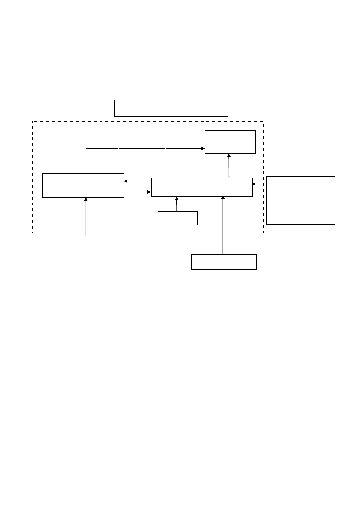
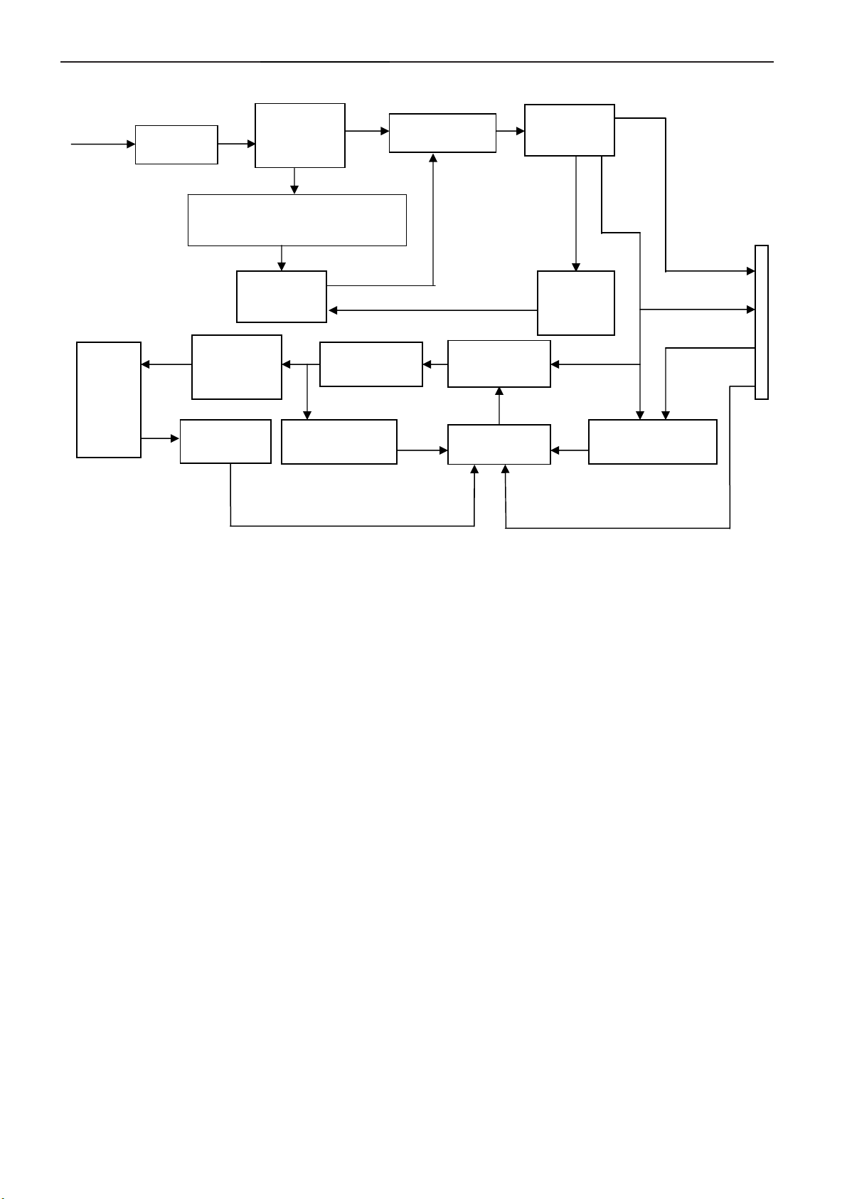
2. LCD Monitor Description
The LCD MONITOR will contain a main board, a power board, an audio board and a key board which house the flat
panel control logic, brightness control logic and DDC.
The power board will provide AC to DC Inverter voltage to drive the backlight of panel and the main board chips
each voltage.
PWPC board
(Include: adapter, inverter)
AC-IN
100V-240V
Monitor Block
CCFL Drive.
Main Board
Keyboard
Flat Panel and
CCFL backlight
HOST Computer
RS232 Connector
For white balance
adjustment in factory
mode
Video signal DDC
4
Page 5
17" LCD Color Monitor AOC 177Vk
3. Operating Instructions
3.1 General Instructions
Press the power button to turn the monitor on or off. The other control buttons are located at front panel of the
monitor.
By changing these settings, the picture can be adjusted to your personal preferences.
The power cord should be connected.
-
Connect the video cable from the monitor to the video card.
-
Press the power button to turn on the monitor, the power indicator will light up.
-
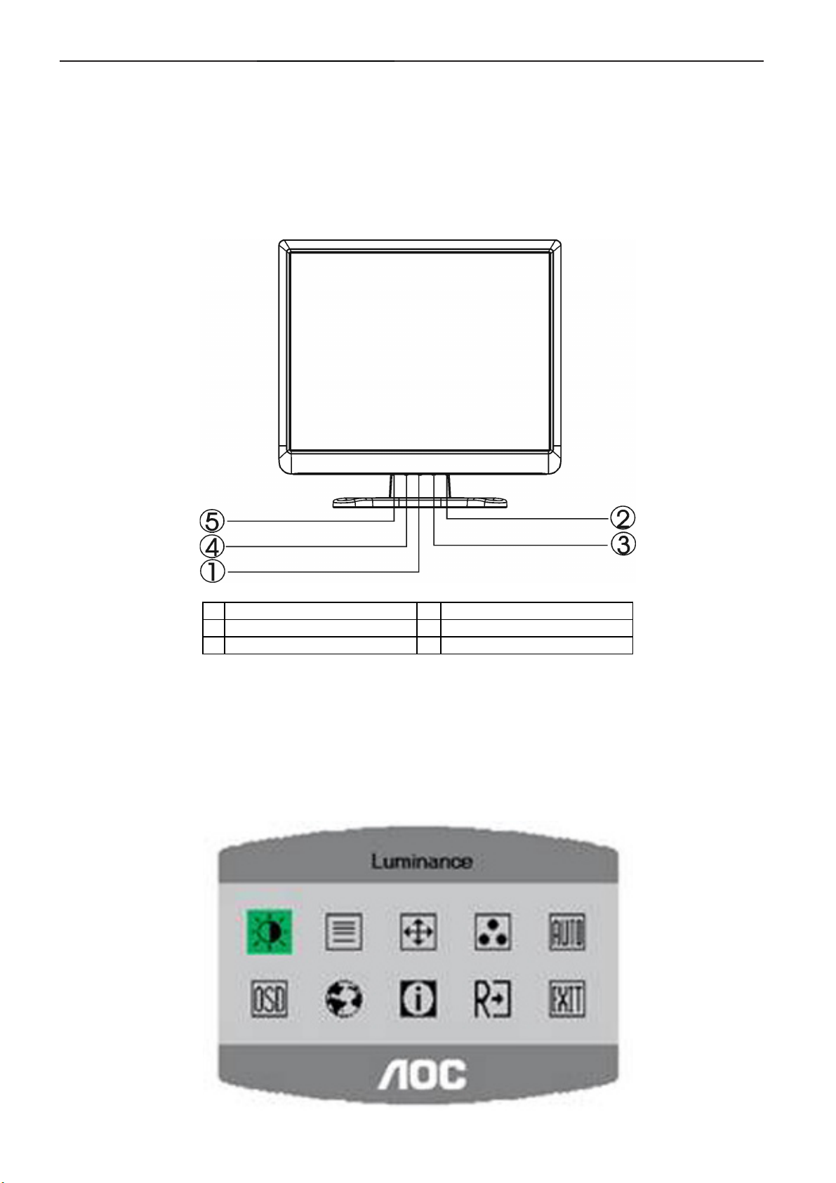
3.2 Control Buttons
1 Power Button/Power Indicator 4 Menu / Enter
2 Volume Control 5 Auto Config / Exit
3 Volume Control
3.3 Adjusting the Picture
1. Press the MENU-button to activate the OSD window .
2. Press +or- to navigate through the functions. Once the desired function is highlighted, press the MENU-button to
activate it. If the function selected has a sub-menu, press +or- again to navigate through the sub-menu functions.
Once the desired function is highlighted, press MENU-button to activate it.
3. Press +or- to change the settings of the selected function.
4. To exit and save, select the exit function. If you want to adjust any other function, repeat steps 2-3.
5
Page 6
17" LCD Color Monitor AOC 177Vk
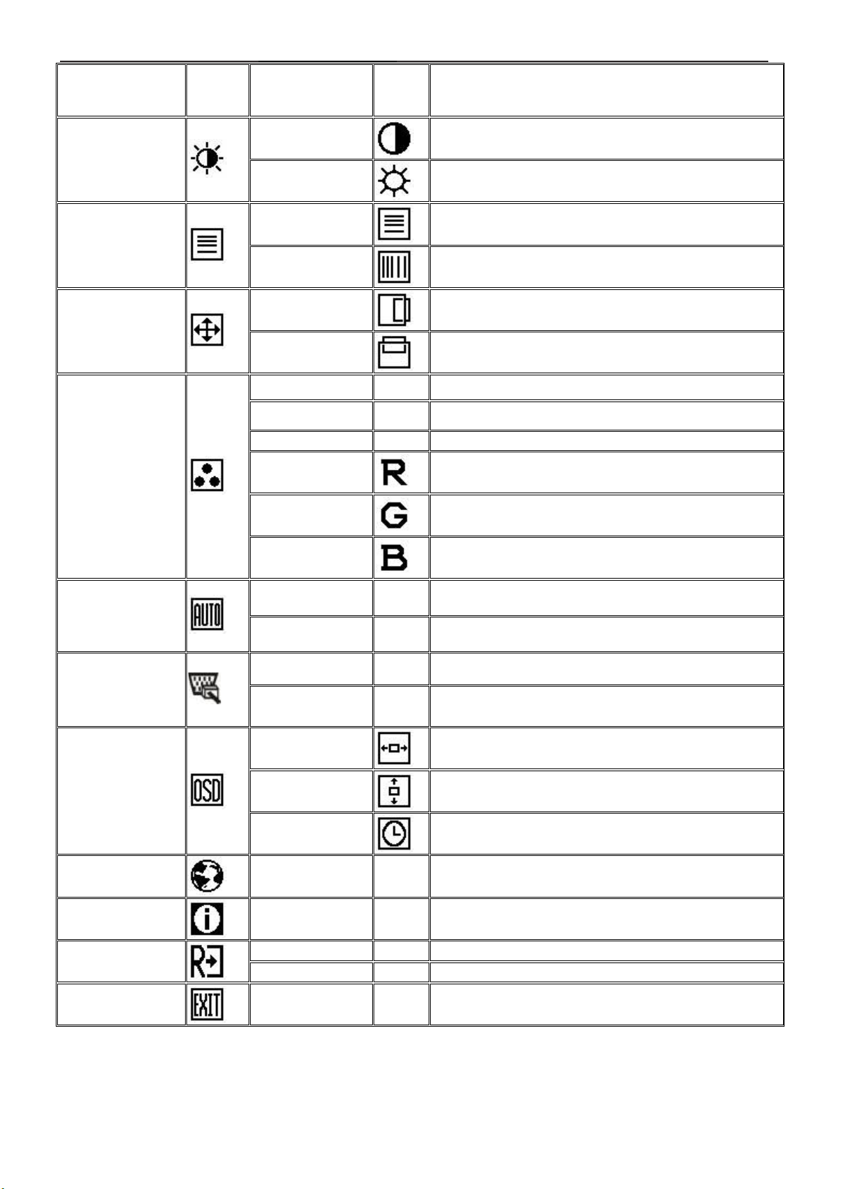
Main Menu Item
Main
Menu
Icon
Sub Menu Item
Sub
Menu
Icon
Description
Luminance
Image Setup
Image Position
Color Temp.
Contrast
Brightness
Focus
Clock
H. Position
V. Position
Warm N/A Recall Warm Color Temperature from EEPROM.
Cool N/A Recall Cool Color Temperature from EEPROM.
sRGB N/A Recall sRGB Temperature from EEPROM.
User / Red
User / Green
Contrast from Digital-register.
Backlight Adjustment
Adjust Picture Phase to reduce Horizontal-Line noise
Adjust picture Clock to reduce Vertical-Line noise.
Adjust the horizontal position of the picture.
Adjust the vertical position of the picture.
Red Gain from Digital-register.
Green Gain Digital-register.
Auto Config
(only Analog-input
Model)
Input Select
(only Dual-Input
Model)
OSD Setup
Language
Information
Reset
User / Blue
Yes N/A
No N/A Do not execute Auto Config, return to main menu.
Analog N/A Select input signal from analog source (D-Sub)
Digital N/A Select input signal from digital source (DVI)
H. Position
V. Position
OSD Timeout
Language N/A Select the language you like.
Information N/A
Yes N/A Clear each old status of Auto-configuration.
No N/A Do not execute reset, return to main menu.
Blue Gain from Digital-register.
Auto Adjust the H/V Position, Focus and Clock of
picture.
Adjust the horizontal position of the OSD.
Adjust the vertical position of the OSD.
Adjust the OSD timeout.
Show the resolution, H/V frequency and input port of
current input timing.
Exit
N/A N/A Exit OSD
6
Page 7
17" LCD Color Monitor AOC 177Vk
4. Input/Output Specification
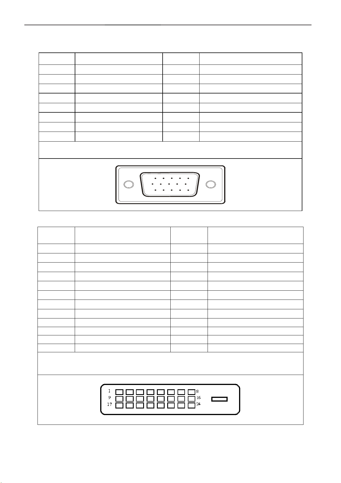
4.1 Input Signal Connector
4.1.1 D-SUB connector
PIN NO. DESCRIPTION PI N NO. DESCRIPTION
1 Video-Red 9 +5V
2 Video-Green 10 Detect Cable
3 Video-Blue 11 Ground
4 GND 12 DDC-Serial data
5 DDC-Return 13 H-sync
6 GND-R 14 V-sync
7 GND-G 15 DDC-Serial clock
8 GND-B
VGA connector layout
15
6
11 15
10
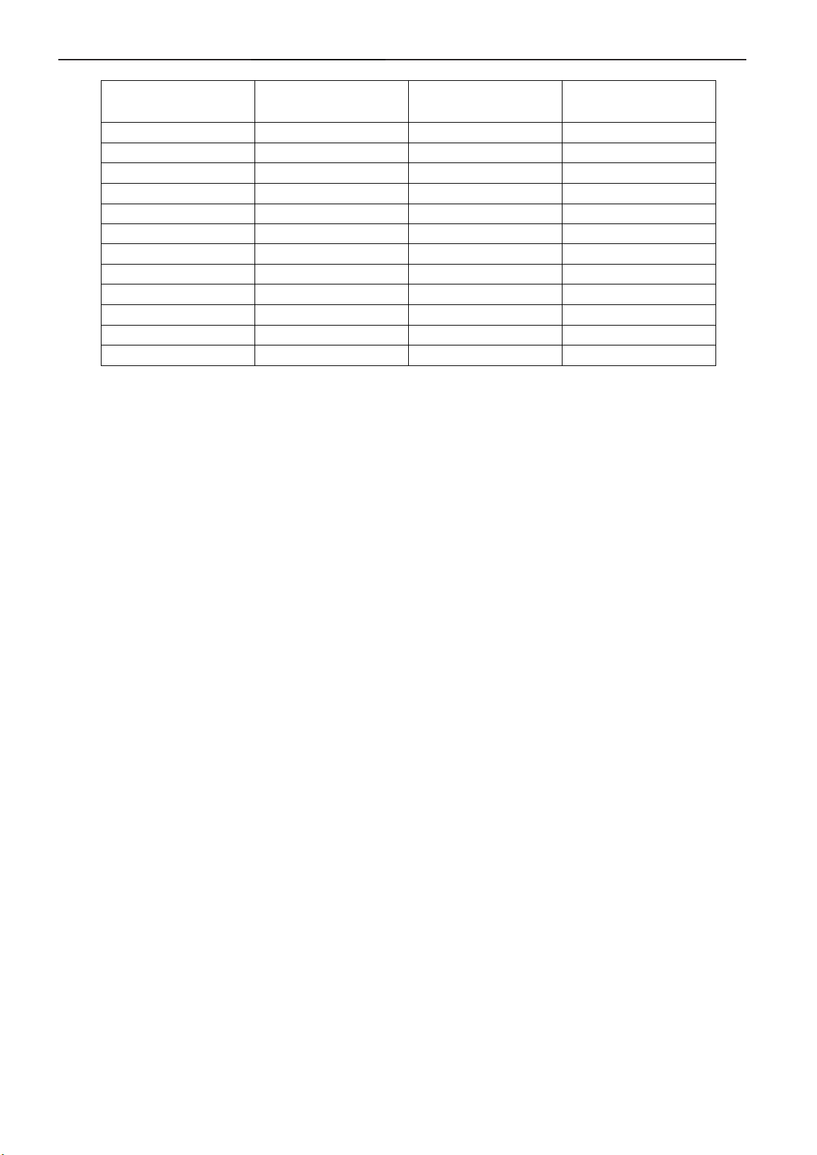
4.1.2 DVI-D connector
Pin No.
1 TMDS Data 2- 13 TMDS Data 3+
2 TMDS Data 2+ 14 +5V Power
3 TMDS Data 2/4 Shield 15 Ground(for+5V)
4 TMDS Data 4- 16 Hot Plug Detect
5 TMDS Data 4+ 17 TMDS Data 0-
6 DDC Clock 18 TMDS Data 0+
7 DDC Data 19 TMDS Data 0/5 Shield
8 N.C. 20 TMDS Data 5-
9 TMDS Data 1- 21 TMDS Data 5+
10 TMDS Data 1+ 22 TMDS Clock Shield
11 TMDS Data 1/3 Shield 23 TMDS Clock +
12 TMDS Data 3- 24 TMDS Clock -
Signal Name
24 - Pin Color Display Signal Cable
Pin No.
Signal Name
7
Page 8
17" LCD Color Monitor AOC 177Vk
4.2 Factory Preset Display Modes
Standard Resolution
Dos-mode 720 x 400 31.47 70
VGA 640 x 480 31.47 60
VGA 640 x 480 37.5 75
SVGA 800 x 600 37.879 60
SVGA 800 x 600 46.875 75
XGA 1024 x 768 48.363 60
XGA 1024 x 768 56.476 70
XGA 1024 x 768 60.02 75
XGA 1024 x 768 48.78 60
XGA 1024 x 768 60.241 75
SXGA 1280 x 1024 64 60
SXGA 1280 x 1024 80 75
Horizontal
Frequency (kHz)
Vertical
Frequency (Hz)
8
Page 9
17" LCD Color Monitor AOC 177Vk
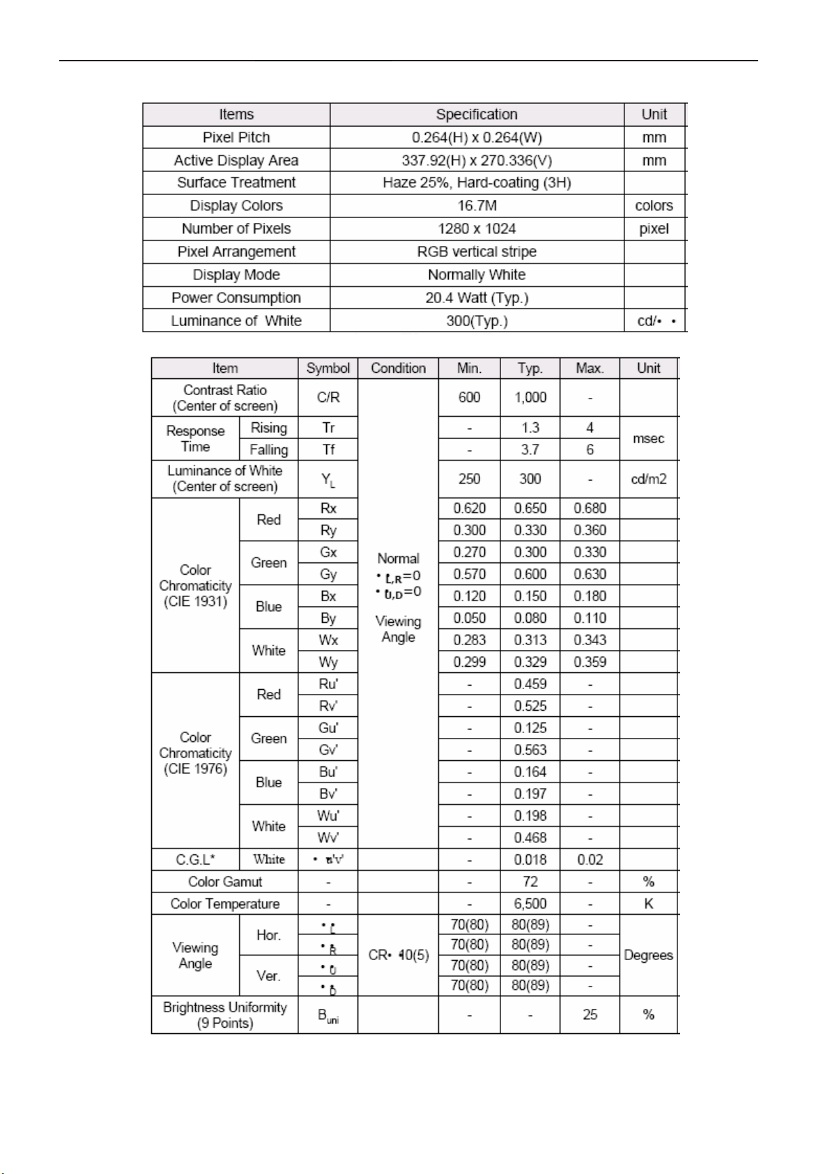
5 Panel Specification
5.1 Display Characteristics
5.2 Optical Characteristics
9
Page 10
17" LCD Color Monitor AOC 177Vk
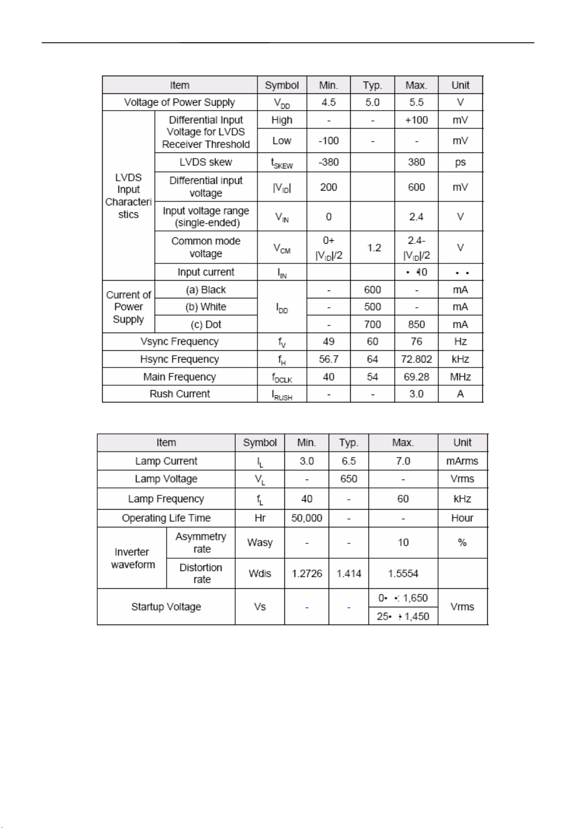
5.3 Parameter guide line for CCFL Inverter
1. TFT LCD Module:
2. Back Light Unit:
10
Page 11
17" LCD Color Monitor AOC 177Vk
6. Block Diagram
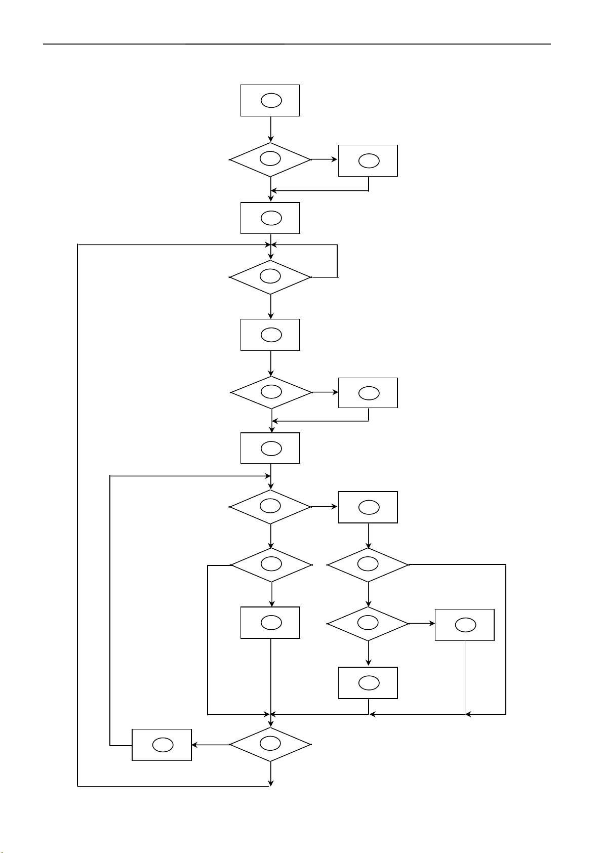
6.1 Software Flow Chat
1
2
N
4
5
Y
6
7
Y
N
N
3
18
9
10
Y
N
N
12
Y
14
19
N
11
13
15
17
N
Y
N
Y
16
Y
11
Page 12

17" LCD Color Monitor AOC 177Vk
1) MCU initialize.
2) Is the EPROM blank?
3) Program the EPROM by default values.
4) Get the PWM value of brightness from EPROM.
5) Is the power key pressed?
6) Clear all global flags.
7) Are the AUTO and SELECT keys pressed?
8) Enter factory mode.
9) Save the power key status into EPROM.
Turn on the LED and set it to green color.
Scalar initializes.
10) In standby mode?
11) Update the lifetime of back light.
12) Check the analog port, are there any signals coming?
13) Does the scalar send out an interrupt request?
14) Wake up the scalar.
15) Are there any signals coming from analog port?
16) Display "No connection Check Signal Cable" message. And go into standby mode after the message
disappear.
17) Program the scalar to be able to show the coming mode.
18) Process the OSD display.
19) Read the keyboard. Is the power key pressed?
12
Page 13
17" LCD Color Monitor AOC 177Vk
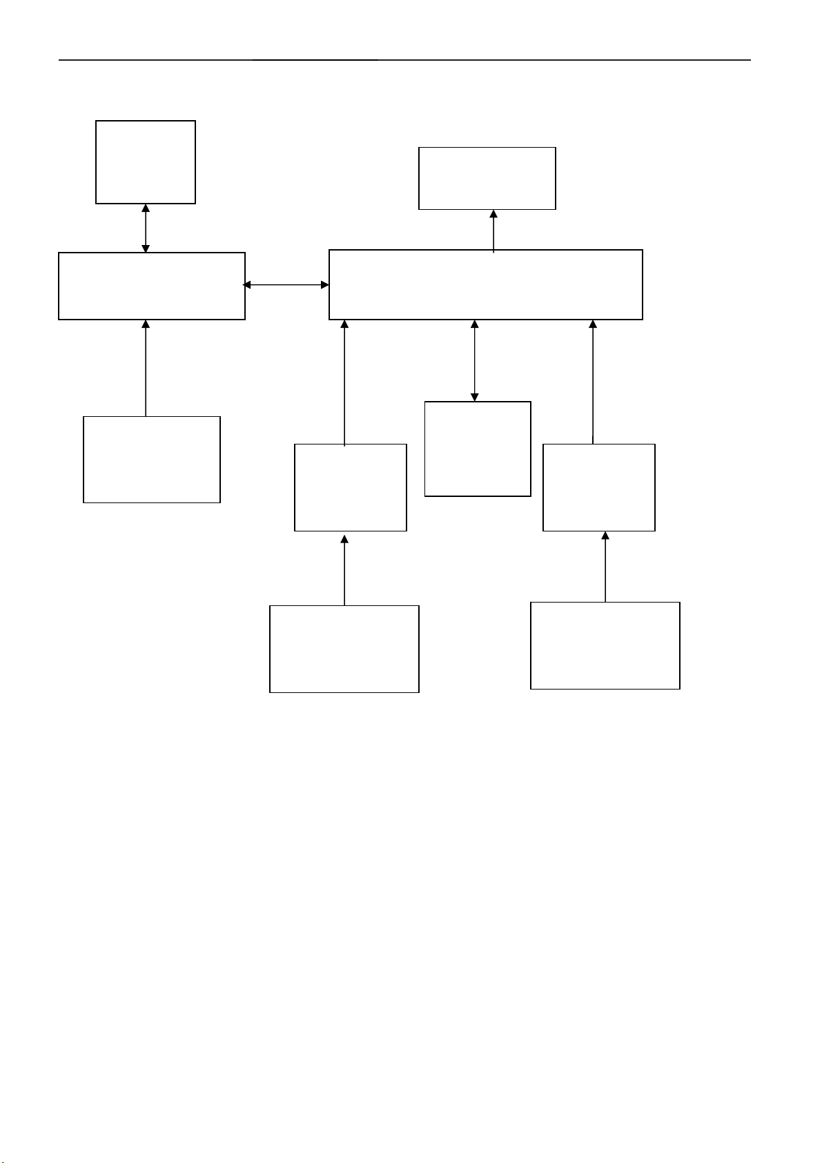
6.2 Electric Block Diagram
6.2.1 Main Board
Crystal
24MHZ
(X301)
MCU
RTD2120L-LFLQFP48
(U402)
OSD
Control Interface
(KEYPAD)
D-Sub
Connector
(CN702)
H sync
V sync
RGB
Panel Interface
(CN101)
Scalar IC RTD2525L-LF
(Include ADC, OSD)
(U401-1)
EEPROM
M24C16
(U302)
DCLK+
DCLK-
RGB
Connector
DVID
(CN701)
EEPROM
M24C02
(U702)
EEPROM
M24C02
(U701)
13
Page 14
17" LCD Color Monitor AOC 177Vk
6.2.2 Inverter / Power Board
AC input
Lamp
EMI filter
Start Circuit: R905、R906、
R907、R908、R909、R910
OSC and
Output
Circuit
Feedback
Circuit
Bridge
Rectifier
and Filter
PWM
Control IC
DC Convert
Circuit
Over Voltage
Protect
Transformer
PWM
Control IC
Rectifier
diode
MOSFET
PWM
Over
Voltage
Protect
12V
ON/OFF
ON/OFF Control
DIM
CN902
5V
14
Page 15

17" LCD Color Monitor AOC 177Vk
7. Schematic
7.1 Main Board
15
Page 16

17" LCD Color Monitor AOC 177Vk
VCC5V
BKLT-VBRI R101
0R05 1/ 10W 5%
C105
NC/1uF/16V
11
1
3
5
7
9
CN101
CONN
2
4
6
8
VCC5V
10
12
5DVCC
R102
4K7 1/10W 5%
R103
NC
Q104
PMBS3904
BKLT-EN
BKLT-VBRI
VCC12V
C110
+
220uF/25V
VBRI
R106
10K 1/10W 5%
C109
100pF/50V
VCC12V
L101
1 2
BKLT-EN
R107
10K 1/10W 5%
600 OHM
C101
220uF/25V
C106
100pF/50V
5DVCC
+
220R 1/10W
D101
SS14
C102
100pF/50V
R105
U101
AIC1084-33PE
R104
4K7 1/10W 5%
Q105
PMBS3904
ADJ
1
R109
NC
L102
1 2
120 OHM
C108
100pF/50V
Vo2Vin
23
C103
100pF/50V
5DVCC
R113
4K7 1/10W 5%
0R05 1/10W 5%
C104
+
100uF/16V
INVON
R110
R111
NC
R112
NC
3DVC C
5DVCC
3DVCC
VCC12V
VOUT(2)
AIC1084-33M
GND(1)
VOUT(2)
VIN(3)
PANELPOWER_ON/OFF
R108
100K 1/10W 5%
Q103
PMBS3904
Q102
PMBS3904
T P V ( Top Victory Electronics C o . , Ltd. )
絬 隔 瓜 絪 腹
Key Component
Date
G2264-1-X-X-4-070702
16
Q101
AO3401
C107
100pF/50V
PANEL_VCC
OEM MOD E L Size
TPV MODEL
PCB NAME
Sheet
177Sa
T76SRDDBF1A3AN 1.1
715G2264-12.0.Power
16Monday, July 02, 2007
of
1
G
AO3401L
Rev
称爹
3
D
2
S
A
Page 17

17" LCD Color Monitor AOC 177Vk
C705,C708,C712由10uF-->15uF;R701,R703,R704,R706,R709,R711由100 ohm-->360 ohm 070215
RED+IN
DDC2_SCL
RXD
RXD
TXD
TXD
D708
TZMC 5V6
1 2
D716 NC/BAV99
3
3DVCC
NC/BAV99
D704
3
Bus_Power
2
1
2
TC+
1
DDC1_SDA
DSUB_5V
ST_DET1
DDC1_SCL
TXD
T1+
Bus_Power
ST_DET2
ST_DET3
ST_DET1
D709
TZMC 5V6
1 2
D717 NC/BAV99
3
D706 NC/BAV99
3
D707
TZMC 5V6
1 2
D718 NC/BAV99
3
D714 NC/BAV99
3
2
T2+
1
2
T0+
1
T2T2+
T1T1+
T0T0+
TC+
TC-
2
T2-
1
2
T0-
1
CN702
1716
1
11
6
2
12
DDC1_S DA
IN-H
IN-V
DDC1_S CL
3DVCC
3
NC/JACK
D710
TZMC 5V6
1 2
D701
BAV99
D723
NC/TZMC5V6
1 2
25
GND
26
GND
IN-V
2
GREEN+IN
1
DDC2_SDA
CN701
RX2RX2+
GND
RX4RX4+
SCL
SDA
VS
RX1RX1+
GND
RX3RX3+
5V
GND
HP
RX0RX0+
GND
RX5RX5+
GND
RXC+
RXC-
1
2
3
4
5
6
7
8
9
10
11
12
13
14
15
16
17
18
19
20
21
22
23
24
IN-H
13
14
15
D711
TZMC 5V6
1 2
D702BAV99
3
D724
NC/TZMC5V6
1 2
7
3
8
4
9
5
10
DB15
DDC1_SDA
2
BLUE+IN
1
D712
TZMC 5V6
1 2
3
DDC2_SCL
DDC2_SDA
D720
NC/TZMC5V6
1 2
DDC1_SCL
D703 BAV99
D713
TZMC 5V6
1 2
2
T1-
1
TC-
DDC2_SCL
DDC2_SDA
R728
NC/4K7 1/ 10W 5%
D705
NC
1 2
RED+IN
DGND
GREEN+IN
DGND
BLUE+IN
DGND
DSUB_5V
ST_DET1
RXD
RED+IN
DGND
GREEN+IN
DGND
BLUE+IN
DGND
D719 NC/BAV99
3
D715 NC/BAV99
3
L701
12
30 OHM
R702
75 OHM +-1% 1/10W
L702
12
30 OHM
75 OHM +-1% 1/10W
L703
12
30 OHM
75 OHM +-1% 1/10W
2
1
2
1
R720 NC/0R05 1/ 10W 5%
R721 NC/0R05 1/ 10W 5%
R722 NC/0R05 1/ 10W 5%
R723 NC/0R05 1/ 10W 5%
R724 NC/0R05 1/ 10W 5%
R725 NC/0R05 1/ 10W 5%
R726 NC/0R05 1/ 10W 5%
R727 NC/0R05 1/ 10W 5%
R701
R713
2K 1/10W
R715
2K 1/10W
360Ω 1/10W
R703
360Ω 1/10W
R704
NC/360Ω 1/ 10W
R706
360Ω 1/10W
R707
100R 1/10W 5%
R709
360Ω 1/10W
R711
360Ω 1/10W
R712
100R 1/10W 5%
R714
100R 1/10W 5%
C705
15pF
R705
C708
15pF
R710
C712
15pF
L704
IN-H
30 OHM
12
IN-V
TX2TX2+
TX1TX1+
TX0TX0+
TXC+
TXC-
C704
0.047uF
C706
0.047uF
C707
NC/0. 047uF
C709
0.047uF
C710
0.047uF
C711
0.047uF
C713
0.047uF
AHS1
C714
NC
AVS1
C703
NC
R1+
R1-
G1+
G1-
SOG1
R708
NC/1M 1/10W 5%
B1+
B1-
AHS1
AVS1
DSUB_5 V
C717
100pF/50V
U702
1
A0
VCC
2
A1
WP
3
A2
SCL
4 5
VSS SDA
M24C 02 -W MN6T P
Bus_Power
C701
NC/100pF /50V
U701
1
A0
VCC
2
A1
WP
3
A2
SCL
4 5
VSS SDA
NC/M24C02-WMN6TP
R707
R704
C710
C707
3DVCC
R729
2K 1/10W
3DVCC
1
C719
150pF
1
C716
NC
D722
BAV70
D721
NC
0.047u
R730
2K 1/10W
C718
150pF
R717
NC
C715
NC
NC
0.047u
0.047u
NC/100R 1/10W 5%
R718
R719
NC/100R 1/10W 5%
RTD2525L
RTD2553V
& 2523B
2
3
8
7
6
2
3
R716
NC
8
7
6
NC
100
DDC1_SCL
DDC1_SDA
100
100
DDC2_SCL
DDC2_SDA
17
T P V ( Top Victory Electronic s Co . , Ltd. )
G2264-1-X-X-4-070702
絬 隔 瓜 絪 腹
Key Component
Date
OEM MOD EL Size
177Sa
TPV MODEL
T76SRDDBF1A3AN 1.1
PCB NAME
715G2264-13.0.Input
Sheet
of
36Monday, J uly 02, 2007
C
Rev
称爹
Page 18

17" LCD Color Monitor AOC 177Vk
DSUB_5V
Bus_Power
D303
D301
LL4148
NC/ LL4148
3DVCC
VOLUME
VBRI
MUTE
STBY
SD2
DDC2_SDA
DDC2_SCL
RXD
TXD
DDC1_SCL
DDC1_SDA
3DVCC
VOLUME
VBRI
INV
MUTE
STBY
SD2
DDC2_SDA
DDC2_SCL
DDC1_SCL
DDC1_SDA
KEY_ AUTO
KEY_ ENTER
IICSCL
IICSDA
KEY_ RIGHT
KEY_ LEFT
D302
LL4148
L301
NC
2 3
Q301
PMBS3906
1
R301
4K7 1/10W 5%
2 3
R302
4K7 1/10W 5%
R331
100R 1/10 W 5%
R343
100R 1/10 W 5%
R306
NC
R303
NC
R333
100R 1/10 W 5%
R334
100R 1/10 W 5%
MCU _VC C
Q302
PMBS3906
1
MCU_RESET
V1
B1
RX
TX
MCU_VCC
C302
100pF/50V
44
45
46
47
48
1
2
3
5
8
9
10
11
12
13
14
MCU _VC C
C301
NC
R304
NC
MCU_RESET
P5.0/PWM0
P5.1/PWM1
P5.2/PWM2
P5.3/PWM3
P5.4/PWM4
P5.5/PWM5
DSCL2/P5.6
DSDA2/P5.7
ASCL1/P3.0/R XD
ASDA1/P3. 1/TXD
P3.2/INT0
P3.3/INT1
P3.4/T0
P3.5/T1
P7.6/CLKO2
P7.7
U402
RTD2120L-LF
X30 1
24.000MHZ
1 2
R336 6K8 1/10W
C303
10pF
4
RST
RTD2120L
XO
XI
15
16
41
VCC
VSS
17
C304
10pF
MCU_VCC
R315
NC
40393837363534
P1.1
P1.2
P1.0/T2
NC
NC
NC
6
7
19
18
GND
P1.3
P1.4
NC
42
MAX810STR
VCC
3
2
1
RST
MCU_RESET
33
P1.5
P1.6
P1.7
VSYN C
P6.7
P6.6/C LKO1
P6.5
P6.4
P6.3/AD C3
P6.2/AD C2
P6.1/AD C1
P6.0/AD C0
NC
NC
43
SDIO2
NC
NC
NC
NC
R316
NC
32
31
30
29
28
27
26
25
24
23
22
21
20
NC
2 3
U301
RST VCC
GND
1
PANELPOWER _ON/OFF
R328
0R05 1/ 10W 5%
5DVCC
R329
1K 1/10W 5%
R330
2K 1/10W
07/05
SDIO2
SDIO1
SDIO0
D1
D2
D3
MCU _VC C
R317
4K7 1/10W 5%
KEY_POW ER
MCU_VCC
C308
100pF/50V
DVI-DSUB SELECT
PANELPOWER _ON/OFF
SDIO2
SDIO1
SDIO0
R342
4K7 1/10W 5%
WP
R327
CRYSTAR_OUT
0R05 1/ 10W 5%
SD1
R319
100R 1/ 10W 5%
LED1
LED2
LED3
ST_DET3
LED1
LED2
LED3
C305
0.1uF/16V
1
A0
2
A1
3
A2
4 5
GND SDA
KEY_EN TER
KEY_AU TO
KEY_R IGHT
KEY_LEF T
CRYSTAR_OUT
ST_DET3
U302
VCC
WP
SCL
AT24C16N-10SU -2.7
KEY_EN TER
KEY_AU TO
B1
V1
RX
TX
KEY_R IGHT
KEY_LEF T
IICSCL
IICSDA
WP
8
7
6
INV
D3
D2
D1
D4
SD1
KEY_POW ER
MCU _VC C
WP
D4
D5
MCU _VC C
RP301
4
5
3
6
2
7
1
8
4.7 KOHM +-5% 1/16W
RP302
1
8
2
7
3
6
4
5
4.7 KOHM +-5% 1/16W
RP303
1
8
2
7
3
6
4
5
4.7 KOHM +-5% 1/16W
RP307
1
8
2
7
3
6
4
5
100Ω 1/16W
RP308
4
5
3
6
2
7
1
8
100Ω 1/16W
RP304
4
5
3
6
2
7
1
8
4.7 KOHM +-5% 1/16W
RP305
4
5
3
6
2
7
1
8
4.7 KOHM +-5% 1/16W
RP306
4
5
3
6
2
7
1
8
4.7 KOHM +-5% 1/16W
RTD_SCLK
RTD_SCSB
RTD_SD3/SDI
IICSCL
IICSDAD5
ST_DET1
POWER
SDIO0
SDIO1
SDIO2
D3
D2
D1
PANELPOWER _ON/OFF
LED2
LED1
KEY_POW ER
SD1
INVON
RTD_SCLK
RTD_SCSB
RTD_SD3/ SDI
ST_DET1
POWER
18
T P V ( Top Victory Electronics Co . , Ltd. )
絬 隔 瓜 絪 腹
Key Component
G2264-1-X-X-4-070702
Date
OEM MODEL Size
TPV MODEL
PCB NAME
177Sa
T76SRDDBF1A3AN 1.1
715G2264-14.0.MCU (RTD2120L)
46Monday, July 02, 2007
Sheet
of
Rev
称爹
B
Page 19

17" LCD Color Monitor AOC 177Vk
R3.3DVCC
L401
12
124
123
122
121
120
119
118
115
114
113
112
111
110
109
106
105
104
103
102
101
100
99
98
97
94
93
92
91
90
89
88
87
86
85
82
81
80
79
78
77
76
75
74
73
+
DGND
C424
100uF/16V
33VRST_REF
RST_OUT
RXO0RXO0+
RXO1RXO1+
RXO2+
RXOCRXOC+
RXO3RXO3+
RXE0RXE0+
RXE1RXE1+
RXE2RXE2+
RXECRXEC+
RXE3RXE3+
600 OHM
RTD_SCLK
RTD_SD3/SDI
R3.3DVCC
DDC2_SCL
DDC2_SDA
RTD_SCLK
RTD_SCSB
RTD_SD3/SDI
SDIO2
SDIO1
SDIO0
R430
0R05 1/10W 5%
R431
0R05 1/10W 5%
R432
0R05 1/10W 5%
R429
0R05 1/10W 5%
Note:
Using the RTD2525L,
the part in the blue frame needs NC
1.8DVCC
3DVCC
L403
NC
C417
C418
NC
NC
R1.8AVCC
+
A
R418
NC
C426
100uF/16V
CRYSTAR_OUT
C422
NC
TX2+
TX2-
TX1+
TX1-
TX0+
TX0-
TXC+
TXC-
C423
100pF/50V
DDC1_SCL
DDC1_SDA
TX2+
TX2-
TX1+
TX1-
TX0+
TX0-
TXC+
TXC-
3DVCC
TMDS_VCC
1.8DVCC
R409
R408
NC
NC
R413
NC
600 OHM
1.8DVCC
12
+
C421
100pF/50V
TMDS_V CC
C419
100uF/16V
L406
600 OHM
C420
100pF/50V
12
L404
1.8DVCC
L402
C414
100pF/50V
CRYSTAR_OUT
B1-
B1+
G1-
G1+
SOG1
R1-
R1+
AHS1
AVS1
600 OHM
B1B1+
G1G1+
SOG1
R1R1+
AHS1
AVS1
12
R1.8DVCC
C425
+
100uF/16V
C415
100pF/50V
DGND
U401
127
XO
128
XI
125
DPLL_VDD
126
DPLL_GND
1
APLL_GND
2
APLL_VDD
3
PLL_TE ST1 / TCO N0 / TC ON3
4
PLL_TE ST2 / TCO N1 / TC ON12
5
TMDS_TST / PWM0 / TCON2
6
REXT
7
TMDS_V DD
8
RX2P
9
RX2N
10
TMDS_G ND
11
RX1P
12
RX1N
13
TMDS_V DD
14
RX0P
15
RX0N
16
TMDS_G ND
17
RXCP
18
RXCN
19
AVS0
20
AHS0
21
ADC_VDD
22
ADC_GND
23
B0+
24
B0-
25
SOG0
26
G0+
27
G0-
28
R0+
29
R0-
30
B1- / V7
31
B1+ / V6
32
G1- / V5
33
G1+ / V4
34
SOG1 / V3
35
R1- / V2
36
R1+ / V1
37
ADC_GND
38
ADC_VDD
39
AHS1 / V0
40
AVS1 / VCLK
R424
DDCSCL1
100R 1/10W 5%
DDCSDA1
R425
100R 1/10W 5%
C416
100pF/50V
47465972839510860718496
116
117
VCCK
VCCK
GNDK
GNDK
DDCSCL1 / TCON4
DDCSDA1 / TCON9
SDIO[3] / TCON0
SDIO[2] / TCON11
SDIO[1] / TCON7
SDIO[0] / TCON13
5157555453
SCSB / TCON12
52
56
50
PVCC
PVCC
PVCC
PVCC
PVCC
NC
SCLK / TCON 3
PWM1 / TCON0 / COUT
BJT_B
BB3P/BBLU7
BB3N/BBLU6
PWM2 / T CON1/TCON7
4858616263646566676869
49
BJT_B
C409
C403
NC
NC
C412
NC
DGND
107
PGND
PGND
PGND
PGND
PGND
33VRST_REF
RESET_OUT
TCON 9 / P WM0
DDCSCL2 / VCLK / TCON4
DDCSDA2 / V7 / TCON6
SCLK / V6 / TCON3
SCSB / V5 / TCON7
SDIO[3] / V4 / TCON9
SDIO[2] / V3 / TCON5
SDIO[1] / V2 / TCON8
SDIO[0] / V1 / TCON10
V0 / TCON2/PWM1
TCON13 / COUT
33VPNLOUT
AG3N / TXO0-
AG3P / TXO0+
ACLKN / TXO1ACLKP / TXO1+
AB1N / TXO2AB1P / TXO2+
AB2N / TXOC-
AB2P / TXOC+
AB3N / TXO3AB3P / TXO3+
BR1N / TXE0BR1P / TXE0+
BR2N / TXE1BR2P / TXE1+
BR3N / TXE2BR3P / TXE2+
BG1N / TXEC-
BG1P / TXEC+
BG2N / TXE3BG2P / TXE3+
BB2P/BBLU5
BB2N/BBLU4
BB1P/BBLU3
BB1N/BBLU2
BCLKP/BGRN7
BCLKN/BGRN6
BG3P/BGRN5
BG3N/BGRN4
70
C413
NC
AR1N
AR1P
AR2N
AR2P
AR3N
AR3P
AG1N
AG1P
AG2N
AG2P
C410
NC
R406
NC
BJT_B
BJT_B
BJT_B
BJT_B
1
2 3
Q401
1
PMBS3906
2 3
3DVCC
MCU_VCC
R410
NC
Q402
PMBS3906
C411
100pF/50V
R405
NC
R407
NC
MCU _R ESE T
A
TX1+
TX1-
TX0+
TX0-
TXC+
TXC-
AVS1RXO2-
AHS1
DGND
B1-
B1+
1
2 3
R428
NC
Q403
PMBS3906
1.8DVC C
TX2-
TX2+
CRYSTAR_OUT
U401-1
1
2
3
4
5
6
7
8
9
10
11
12
TMDS_VCC
4847464544434241403938
XIN
V0/RX2N
VCLK/RX2P
TMDS_VDD
V1/REXT
V2/RX1P
V3/RX1N
V4/RX0P
V5/RX0N
V6/RXCP
V7/RXCN
AVS
AHS
ADC_GND
B-
B+
B(1)
RTD2025L QFN-48
G-G+R-R+ADC_VD D
1314151617181920212223
G1-
SOG1
R1-
R1+
C(3)
PMBS3906
E(2)
RXO0-
RXO0-
RXO0+
RXO0+
RXO1-
RXO1-
RXO1+
RXO1+
RXO2-
RXO2-
RXO2+
RXO2+
RXOC-
RXOC-
RXOC+
RXOC+
RXO3-
RXO3-
RXO3+
RXO3+
RXE0-
RXE0-
RXE0+
RXE0+
RXE1-
RXE1-
RXE1+
RXE1+
RXE2-
RXE2-
RXE2+
RXE2+
RXE3-
RXE3-
RXE3+
RXE3+
RXEC-
RXEC-
RXEC+
RXEC+
DDCSCL1
RTD_SCLK
DDCSDA1
SCL
DDCSCL/PWM0
DDCSDA/PWM1/IRQ
BJT_B
VCCK
BJT_B
R1.8DVCC
R1.8AVCC
RXO0+
DGND
RTD_SD3/SDI
RXO0-
R1.8DVCC
37
SDA
VCCK
PGND
TXO0-
TXO0+
TXO1-
TXO1+
TXO2-
TXO2+
TXOC-
TXOC+
TXO3-
TXO3+
TXE0-
TXE0+
TXE1-
TXE1+
PGND
TXE3+
TXE3-
TXE2+
TXE2-
24
DGND
RXE3+
RXE2+
RXE3-
RXE2-
RXO1-
36
RXO1+
35
RXO2-
34
33
RXO2+
RXOC-
32
RXOC+
31
RXO3-
30
RXO3+
29
RXE0-
28
RXE0+
27
RXE1-
26
RXE1+
25
R433
0R05 1/10W 5%
R434
0R05 1/10W 5%
RTD2525L
RTD2523B
& RTD2553V
RXEC-
RXEC+
R433
open
R434
0
0
open
19
T P V ( Top Victory Electronics Co . , Ltd. )
G2264-1-X-X-4-070702
絬 隔 瓜 絪 腹
Key Component
Date
OEM MODEL Size
177Sa
TPV MODEL
T76SRDDBF1A3AN 1.1
715G2264-15. 0.RTD2525L
PCB NAME
56Monday, July 02, 2007
Sheet
of
C
Rev
称爹
Page 20

17" LCD Color Monitor AOC 177Vk
OUT-L-
VOL
RXO0-
RXO0+
RXO1-
RXO1+
RXO2-
RXO2+
RXOC-
RXOC+
RXO3-
RXO3+
RXE0-
RXE0+
RXE1-
RXE1+
RXE2-
RXE2+
RXE3-
RXE3+
RXEC-
RXEC+
RXO0RXO0+
RXO1RXO1+
RXO2RXO2+
RXOCRXOC+
RXO3RXO3+
RXE0RXE0+
RXE1RXE1+
RXE2RXE2+
RXE3RXE3+
RXECRXEC+
11
13
1
3
5
7
9
CN501
CONN
CN503
RXO0-
1
RXO1-
3
RXO2-
5
7
RXOCRXO3-
9
RXE0-
11
RXE1-
13
15
RXE2RXEC-
17
RXE3-
19
21
23
NC
L501
600 OHM
L502
1 2
600 OHM
R522
R521
4K7 1/10W 5%
4K7 1/10W 5%
2
4
6
8
10
12
14
C501
1uF/16V
OUT-R+OUT-L+
OUT-R-
R502
10K 1/10W 5%
VCC1 2V
VCC12V
12
5DVCC
R517 0R05 1 /10W 5%
R518 0R05 1 /10W 5%
DVI-DSUB SELECT
R501
1K 1/10W 5%
KEY_ AUTO
KEY_ RIGHT
SD2
RK7002
Q504
PANEL_VCC
C504
+
100uF/16V
STBY
MUTE
DVI-DSUB SELECT
LED_GRN
KEY_AU TO
KEY_R IGHT
SD2
VOLUME
STBY
MUTE
POWER
ST_DET2
15.4mA
R506
4K7 1/10W 5%
LED_GRN
RP501
4
3
2
1
100Ω 1/16W
RXO0+
2
4
RXO1+
RXO2+
6
RXOC+
8
RXO3+
10
RXE0+
12
RXE1+
14
RXE2+
16
RXEC+
18
RXE3+
20
22
24
C502
1
C506
100pF/50V
100pF/50V
R508
4K7 1/10W 5%
R512
4.7 KOHM +-5% 1/4W
3DVCC
R509
120R 1/10W
23
Q501
PMBS3906
5
6
7
8
C505
100pF/50V
C508
100pF/50V
LED1
C509
NC
GRN
AUTO
RIGHT
POWER
OUT-L+
OUT-L-
LED_BLUE
CN502
1
3
5
7
9
11
13
15
CONN
3DVCC
23
2
4
6
8
10
12
14
16
R519
0R05 1/10W 5%
Q503
1
PMBS3906
ORANGE
ENTER
LEFT
OUT-R+
OUT-R-
R520
4K7 1/10W 5%
PANEL_VCC
LED2
C512
100pF/50V
LED_ORAN GE
RP502
4
3
2
1
100Ω 1/16W
C507
100pF/50V
LVDS Panel ( Normal Type )
RXO0-
RXO0-
RXO0+
RXO0+
RXO1-
RXO1-
RXO1+
RXO1+
RXO2-
RXO2-
RXO2+
RXO2+
RXOC-
RXOC-
RXOC+
RXOC+
RXO3-
RXO3-
RXO3+
RXO3+
RXE0-
RXE0-
RXE0+
RXE0+
RXE1-
RXE1-
RXE1+
RXE1+
RXE2-
RXE2-
RXE2+
RXE2+
RXEC-
RXEC-
RXEC+
RXEC+
RXE3-
RXE3-
RXE3+
RXE3+
R505 NC
R507 NC
3DVCC
R510
120R 1/10W
23
5
6
7
8
Q502
1
PMBS3906
LED_BLUE
LED_ORANGE
KEY_EN TER
KEY_LEF T
R511
4K7 1/10W 5%
CN504
1
2
3
4
5
6
7
8
9
10
11
12
13
14
15
16
17
18
19
20
21
22
23
24
25
26
27
28
29
30
CONN
LED3
KEY_EN TER
KEY_LEF T
20
T P V ( Top Victory Electronics Co . , Ltd. )
絬 隔 瓜 絪 腹
Key Component
G2264-1-X-X-4-070702
Date
OEM MODEL Size
TPV MODEL
PCB N AME
177Sa
T76SRDDBF1A3AN 1.1
715G2264-16.0.Out put
of
66Monday, July 02, 2007
Sheet
Rev
称爹
B
Page 21

17" LCD Color Monitor AOC 177Vk
7.2 Power Board
1
+
BD901
2A 800V
3
R900
330K 1/8W
2
-
4
2
3
L902
L
1
4
2
3
L901
L
1
4
C909 0. 47uF/250V
R901
330K 1/8 W
R902
330K 1/8W
3
12
CN901
SOCKET
C902
0.001uF/ 250V
C901
0.001uF/ 250V
12
t
NR901
5 ohm/8A
F901
T2.5A/250V
1
2
0.1uF/50V
GND1
1
GND
HS3 D920
HEAT SIN K
+
C912
C907
100uF/450 V
IC901
LD7575
R911
100K 1/1 0W
1
GND
C916
0.1uF/ 50V
7
穝
470PF/25V
GND2
HS4 Q900
1
2
HEAT SINK
R905
10K 1/8 W
8
HV
LD7575
N.C
RT1CS
GND
4
C914
OUT
T901
4
C905
0.0033uF/250V
C900
0.0022uF/250V
IC902
PC123FY 2 4P
O
2
O
1
43
IC921
KIA431
O
O
R909
100K 2W
C910
1500pF/1KV
D901
UF4003PT
+
C911
22uF/50V
N.C ZD901
RLZ27B
D910
1 2
6
COMP
2
LL4148WP
VCC
R912
5
10 1/8W
3
C913
220pF/50V
10K 1/10W
R913
1K 1/10W
D911
C915
R915
NC
NC
D900
BA159GPT
R910
7R5 1/ 8W
Q900
FQPF8N60C
1
3 2
R916
0.43 2W
Q910
1
NC
3 2
R951
R952
47 1/8W
C920
R953
0.001uF/ 500V
47 1/8W
47 1/8W
D920
3
SBT150-10LS
2
12
11
10
86
7
9
12
R954
47 1/8W
R955
47 1/8W
R956
47 1/8W
1
3
1
D922
3A/60V
2
N.C D921
FMW-2156
C921
0.001uF/ 500V
R922
470 1/4W
R925
1K 1/10W
C928
0.1uF/ 50V
R928
1K 1/4W
ZD921
RLZ13B
1 2
D915
R927
100 1/ 10W
+
C922
680uF/25V
+
1000uF/16V
LL4148WP
蔼跋
19mm,ㄏノ13x16size
L921
+
C923
+
C924
680uF/25V
680uF/25V
C926
+
C932
470uF/16V
ZD922
RLZ5.1B
1 2
D916
LL4148WP
R923
10K 1/10 W
C929
0.1uF/ 50V
R930
100 1/10W
RJ901
0 1/8W
L922
R924
3.6K 1/ 10W 1%
R929
2.4K 1/ 10W 1%
3.5UH
+
470UF/25V
3.5UH
C925
+
R926
33K 1/10W 1%
RJ902
0 1/8W
C927
470UF/ 16V
CN902
CONNECTOR
R931
10K 1/8W
1
2
3
4
5
6
7
8
9
10
F902
0 1/8W
ZD920
TPSMP9 1A-E3 DO-220AA
1 2
F903
0 1/8W
ON/OFF
+5V
C931
0.1uF/50V
C930
0.1uF/ 50V
AOC (Top Victory) Electronics Co., Ltd.
Tit le
Size Document Number Rev
Custom
Date: Sheet
audio 12V
DIM
PWPC1742HDE2P(715G1823-1)
Monday, May 29, 2006
+12V
+5V
J901
TIN COATED
J902
TIN COATED
J903
TIN COATED
J904
TIN COATED
J905
TIN COATED
J906
TIN COATED
J907
TIN COATED
J908
TIN COATED
J909
TIN COATED
J910
TIN COATED
J911
TIN COATED
11
of
A
21
Page 22

17" LCD Color Monitor AOC 177Vk
RJ801
0 1/8W
+12V
ON/OFF
AOC (Top Victory) Electronics Co., Ltd.
Tit le
Size Doc ument Number R ev
Date: Sheet
R803
10K 1/10W
N.C R806
470 1/8W
+5V
N.C R838
0 1/8W
DIM
R808
470K 1/8W
C803
0.01UF /50V
J811
TIN COATED
J812
TIN COATED
J818
TIN COATED
J823
TIN COATED
2. FOR 17" 4 LAMPS INVERTER
PWPC1742HDE1
Monday, May 29, 2006
300K 1/8W
PMBS3904
J814
TIN COATED
J819
TIN COATED
RJ802
0 1/8W
R802
Q801
1
N.C C801
0.1uF/ 50V
R811
150K 1/10W
1
32
C804
2.2uF/ 25V
J815
TIN COATED
J820
TIN COATED
R812
10K 1/10W
RJ803
R804
10K 1/8W
R809
1M 1/10W
J816
TIN COATED
J821
TIN COATED
of
ZD801
RLZ5.6B
RJ804
0 1/8W
PMBS3904
C805
1000PF/50V
A
0 1/10W
32
Q802
PMBS3904
11
R805
470 1/8W
Q803
1
R813
J817
TIN COATED
J822
TIN COATED
穝糤箂ン
C811
470UF/25V
32
VCC
R807
22 1/8W
R810
100K 1/10W
R814
1M 1/ 10W
470UF/25V
56K 1/10W
C820
C828,C829
+
C806
1UF/ 25V
+
N.C C828
0.1uF/50V
AM9945
10 1/10W
Q805
R842
N.C C829
0.1uF/50V
R818
15 1/8W
C812
N.C R839
1500PF/50V
33K 1/8W
6
8
D1N7D1N
S1N1G1N2S2P3G2P
IC801
1
DRV1
2
VDDA
3
TIMER
4
DIM
5
ISEN
6
VSEN
7
OVPT
NC18NC2
OZ9938
R828
C822
N.C R840
1500PF/50V
33K 1/8W
N.C C814
1000P/50V
D2P5D2P
4
PGND
DRV2
GNDA
CT
SSTCMP
LCT
ENA
15 1/8W
1000P/50V
8
S1N1G1N2S2P3G2P
16
15
14
13
12
11
10
9
N.C C815
6
D1N7D1N
R819
15 1/8W
C813
1500PF/50V
R837
10 1/10W
R829
C823
Q806
AM9945
D2P5D2P
4
PT801
80GL17T-36-DN
5
3
4
1 8
15K 1/10W
C830
100PF/50V
1
R815
R816
100K 1/10W
R820
1M 1/ 10W
7
C816
10PF/3KV
C817
3PF/3KV
R821
100K 1/10W
C818
270PF/50V
2
N.C R823
D801
BAV70
3
R817
C831
75K 1/10W
100PF/50V
36K 1/10W 1%
N.C R844 39K 1/10W
R822
3M / 1/2W
R827
3.6K 1/ 10W 1%
17" R841 =390ohm
R841
R826
C819
0.022UF/ 25V
390 1/10W 1%
19" R841 = 300ohm
300 1/10W 1%
R836
1K 1/10W
2
3
1
D802
BAV99
R825
560 1/10W
C835
1UF/25V
C836
1UF/25V
CN801
2
1
33G8021-2D-U
CN802
2
1
33G8021-2D-U
1Mohm brust frequency:400HZ
C807
0.01UF /50V
6800PF/50V
80GL19T-36-DN
5
3
4
15 1/8W
1500PF/50V
1 8
C832
100PF/50V
PT802
R830
15K 1/10W
1
3
0.047UF /50V
7
D803
BAV70
2
C810
560PF/50V
C825
10PF/3KV
R831
100K 1/10W
C826
3PF/3KV
C827
270PF/50V
C833
100PF/50V
N.C R833
75K 1/10W
R832
3M / 1/2W
R834
3.6K 1/ 10W 1%
CN803
R843
1K 1/10W
3
D804
BAV99
R835
560 1/10W
2
1
C837
1UF/25V
C838
1UF/25V
1
2
33G8021-2D-U
CN804
1
2
33G8021-2D-U
C809
C808
22
Page 23

17" LCD Color Monitor AOC 177Vk
8. PCB Layout
8.1 Main Board
23
Page 24

17" LCD Color Monitor AOC 177Vk
24
Page 25

17" LCD Color Monitor AOC 177Vk
25
Page 26

17" LCD Color Monitor AOC 177Vk
8.2 Power Board
26
Page 27

17" LCD Color Monitor AOC 177Vk
27
Page 28

17" LCD Color Monitor AOC 177Vk
28
Page 29

17" LCD Color Monitor AOC 177Vk
8.3 Key Board
8.4 Audio Board
29
Page 30

17" LCD Color Monitor AOC 177Vk
9. Maintainability
9.1 Equipments and Tools Requirement
1. Voltmeter.
2. Oscilloscope.
3. Pattern Generator.
4. DDC Tool with an IBM Compatible Computer.
5. Alignment Tool.
6. LCD Color Analyzer.
7. Service Manual.
8. User Manual.
30
Page 31

17" LCD Color Monitor AOC 177Vk
9.2 Trouble Shooting
9.2.1 Main Board
1. NO SCREEN APPEAR
No power
Press power key and look
if the picture is normal
Please reinsert and make sure
the AC of 100-240 is normal
Measure U702 PIN2=3.3V
X301 oscillate waveforms
are normal
No power
OK
OK
OK
NG
NG
NG
NG
Replace X301
Reinsert or check the
power section
Measure CN701 PIN5/6=12V?
Measure CN701 PIN9/10=5V?
OK
Replace U702
NG
Check power
section
Replace U401-1
OK
Replace U402
31
Page 32

17" LCD Color Monitor AOC 177Vk
No picture (LED orange)
Measure U702 PIN2=3.3V
Check if the sync signal from computer
is output and video cable is connected
normally
No picture
OK
X401 oscillate waveforms are
normal
OK
OK
Replace U401-1
OK
Replace U402
NG
NG
NG
Replace U702
Replace X401
Input the sync signal of
computer, or change the
cable
32
Page 33

17" LCD Color Monitor AOC 177Vk
9.2.2 Power Board
1. No Power
Check CN902 pin3= 12V
NG
Check AC line volt 110V or 220V
OK
NG
Check AC input
Check the voltage of C907(+)
OK
NG
Check bridge rectified circuit and F901 circuit
Check start voltage for the pin3 of IC901
OK
NG
Check R912,R913 and Change IC901
Check the auxiliary voltage is bigger than
10V and smaller than 20V
OK
NG
1) Check IC901
2) Check OVP circuit
Check IC901 pin8 PWM wave
OK
NG
Check IC901
Check Q900,R910,T901,D900,D901
33
Page 34

17" LCD Color Monitor AOC 177Vk
2. W/LED No Backlight
Check C811 (+) =12V
NG OK
Change Q803
Check ON/OFF signal
OK
NG
Check main board
Check IC801 pin6=12V
OK
NG
Change Q805 or Q806
Check the pin1 of IC801 have saw tooth wave
Change IC801
Check D801/D802/D803/D804 have the output of square wave at
OK
NG
Check R820/R821/C817/R822
Check R830/R831/C826/R832
Check the resonant wave of pin2 & pin5 for PT801/PT802
OK
Check the output of PT801/PT802
NG
Check R819/C813/R818/C812
Check R828/C822/R829/C823
OK
NG
Check connecter & lamp
Change PT801/PT802
34
Page 35

17" LCD Color Monitor AOC 177Vk
9.2.3 Key Board
OSD is unstable or not working
Is Key Pad Board connecting normally ?
Y
Is Button Switch normally ?
Y
N
N
Connect Key Pad Board
Replace Button Switch
Is Key Pad Board normally ?
N
Replace Key Pad Board
Y
Check Main Board
35
Page 36

17" LCD Color Monitor AOC 177Vk
10. White- Balance, Luminance Adjustment
Approximately 30 minutes should be allowed for warm up before proceeding White-Balance adjustment.
1. How to do the Chroma-7120 MEM. Channel setting
A. Reference to chroma 7120 user guide
B. Use “ SC” key and “ NEXT” key to modify x, y, Y value and use “ID” key to modify the
TEXT description Following is the procedure to do white-balance adjust
2. Setting the color temp. you want
A. MEM.CHANNEL 3 (7800 color):
7800 color temp. parameter is x = 296 ±20, y = 311 ±20, Y = 180 cd/m
B. MEM.CHANNEL 4 (6500 color):
6500 color temp. parameter is x = 313±20, y = 329 ±20, Y =180 cd/m2
3. Into factory mode of 177Vk
Turn on power, press the MENU button, pull out the power cord, and then plug the power cord. Then the factory
OSD will be at the left top of the panel.
4. Bias adjustment:
2 ,
Set the Contrast
to 50; Adjust the Brightness to 90.
5. Gain adjustment:
Move cursor to “-F-” and press MENU key
A. Adjust C2 (7800) color-temperature
1. Switch the Chroma-7120 to RGB-Mode (with press “MODE” button)
2. Switch the MEM. Channel to Channel 3 (with up or down arrow on chroma 7120)
2
3. The LCD-indicator on chroma 7120 will show x = 296 ±20, y = 311 ±20, Y =180 cd/m
4. Adjust the RED of color1 on factory window until chroma 7120 indicator reached the value R=100
5. Adjust the GREEN of color1 on factory window until chroma 7120 indicator reached the value G=100
6. Adjust the BLUE of color1 on factory window until chroma 7120 indicator reached the value B=100
7. Repeat above procedure (item 4,5,6) until chroma 7120 RGB value meet the tolerance =100±5
B. Adjust C1 (6500) color-temperature
1. Switch the chroma-7120 to RGB-Mode (with press “MODE” button)
2. Switch the MEM.channel to Channel 4(with up or down arrow on chroma 7120)
2
3. The LCD-indicator on chroma 7120 will show x = 313 ±20, y = 329 ±20, Y = 180 cd/m
4. Adjust the RED of color3 on factory window until chroma 7120 indicator reached the value R=100
5. Adjust the GREEN of color3 on factory window until chroma 7120 indicator reached the value G=100
6. Adjust the BLUE of color3 on factory window until chroma 7120 indicator reached the value B=100
7. Repeat above procedure (item 4,5,6) until chroma 7120 RGB value meet the tolerance =100±5
C. Turn the Power-button off to quit from factory mode.
36
Page 37

17" LCD Color Monitor AOC 177Vk
11. Monitor Exploded View
NO. DESCRIPTION PART NO. NO. DESCRIPTION PART NO.
1 LENS Q33G4986 9 STAND-TOP Q34G1842
2 KEY PAD Q33G4985 10 VESA BKT 15G5786
3 BEZEL Q34G1841 11 STAND-BOTTOM Q34G1843
4 PANEL 12 CABLE Q33G4987
5 MAINFRAME H15G8312 13 BASE BKT Q15G8356
6 SHIELD Q85G 740 14
7 BACK COVER Q34G1840 15 BASE Q34G1845
8 HINGE H37G0002 16 HINGE BKT
37
Page 38

17" LCD Color Monitor AOC 177Vk
12. BOM List
T77SRTDBF1ACANE
Location Part NO. Description
AUPC780KK6AP AUDIO BOARD
CBPC7SRTA1H1 MAIN BOARD
KEPC7HC6 KEY BOARD
PWPC742HE1P POWER BOARD
15G5786 1 BKT VESA
26G 800504 3H BARCODE
40G 58162435A MANUAL LABEL
41G780061553A TCO03 CARD
44G3798 1 EPS(L)
44G3798 2 EPS(R)
44GH600 1 HANDLE2
50G 600 4 HANDLE1
52G 1186 SMALL TAPE
78G 322 1A KL SPK 8OHM 1.5W KUAIDA
78G 322 1A KR SPK 8OHM 1.5W KUAIDA
89G 17356G553 AUDIO CABLE
89G 725HAA DB SIGNAL CABLE
89G1745GAADVI SIGNAL CABLE
89G179E30NE03 FFC CABLE
89G404A15N YH POWER CORD
95G801416TE13 WIRE HARNESS
D1G1730 8120 SCREW
D1G1730 8120 SCREW
M1G 130 5120 SCREW M3X5
M1G 330 4120 SCREW
M1G 330 6 47 CR3 SCREW 3X6mm
M1G1140 6120 SCREW
M1G2640 10 47 CR3 SCREW
Q1G 330 8120 SCREW 3X8mm
Q1G 330 10 47 CR3 SCREW (T3X10)
Q1G1030 8120 SCREW
705GH734071 ASS'Y
750GLS70U315CN PANEL LTM170EU-L31 8TM
H15G8312 N 8A MAIN FRAME
H40G 17061547A ID LABEL
H40G 58161544B AOC LOGO LABEL
H44G3798615 5A CARTON
H45G 87 4 3 R PE BAG FOR BASE
H45G 87 18 2H A EPE COVER
H52G6025 16 29 INSULATE SHEET
H70G200761536A CD MANUAL
Q15G8313 1 AC SOCKET BRACKET
Q33G4985 GM 1L KEY BUTTON
Q33G4986 1 1C POWER LENS
Q33G4987 GM 1L CABLE CLAMP
Q34G1840 GM 1B REAR COVER
Q34G1841 YDA1B BEZEL
Q41G7800615A26 QSG
Q45G 76 28 H A PE BAG FOR MANUAL
Q45G 88606 14 R PE BAG
Q52G 1185 65 MIDDLE TAPE
Q85G 740 1 1A SHIELD
CN202 33G802414D H 2*7PIN DUAL ROW RIGHT A
38
Page 39

17" LCD Color Monitor AOC 177Vk
C208 67G215V471 3N ELCAP 470UF +-20% 16V 1
CN201 88G 30214K PHONE JACK 5PIN
U201 Q90G6093 2 HEAT SINK
U201 56G 616 1 TDA7496L BY ST
R207 61G0603102 RST CHIPR 1KOHM +-5% 1/
R208 61G0603102 RST CHIPR 1KOHM +-5% 1/
R201 61G0603183 RST CHIPR 18KOHM +-5% 1
R203 61G0603183 RST CHIPR 18KOHM +-5% 1
R210 61G0603203 RST CHIPR 20KOHM +-5% 1
R211 61G0603203 RST CHIPR 20KOHM +-5% 1
R202 61G0603204 RST CHIPR 200KOHM +-5%
C211 65G0805101 31 CHIP 100PF 50V NPD 0805
C212 65G0805101 31 CHIP 100PF 50V NPD 0805
C203 65G0805104 32 CAP 0805 0.1U +-10% 50V
C213 65G0805104 32 CAP 0805 0.1U +-10% 50V
C204 65G0805474 22 CHIP 0.47UF 25V X7R 080
C206 65G0805474 22 CHIP 0.47UF 25V X7R 080
715G1841 2 AUDIO BOARD PCB
J201 95G 90 23 TINCOATEDCOPPER
J203 95G 90 23 TINCOATEDCOPPER
J205 95G 90 23 TINCOATEDCOPPER
J207 95G 90 23 TINCOATEDCOPPER
R301 61G172S18352T RST CFR 18KOHM +-5% 1/4
R302 61G172S18352T RST CFR 18KOHM +-5% 1/4
R212 61G172S22452T RST CFR 220KOHM +-5% 1/
C209 67G 2151007NT ELCAP 10UF +-20% 50V 10
C210 67G 2151007NT ELCAP 10UF +-20% 50V 10
C201 67G215B4713HT ELCAP 470UF +-20% 16V 1
C202 67G215B4713HT ELCAP 470UF +-20% 16V 1
C205 67G215B4713HT ELCAP 470UF +-20% 16V 1
C207 67G215B4713HT ELCAP 470UF +-20% 16V 1
CN501 33G801714A BH PIN HEADER 2*7 R/A
CN504 33G801930F CH JS FFC CONN .1.0MM 30P
CN101 33G8027 12 WAFER 2*6P 2.0MM R/A
CN502 33G8027 16 WAFER 16PIN 2.0mm DIP
40G 45762412B CBPC LABEL
C101 67G215V221 4N ELCAP 220UF +-20% 25V 1
C110 67G215V221 4N ELCAP 220UF +-20% 25V 1
C104 67G305V101 3 ELCAP 100UF +-20% 16V 1
C419 67G305V101 3 ELCAP 100UF +-20% 16V 1
C424 67G305V101 3 ELCAP 100UF +-20% 16V 1
C425 67G305V101 3 ELCAP 100UF +-20% 16V 1
C426 67G305V101 3 ELCAP 100UF +-20% 16V 1
C504 67G305V101 3 ELCAP 100UF +-20% 16V 1
CN702 88G 35315F HD D-SUB CONN F ATTACHED
CN701 88G 35424F N DVI 24PIN CONN F
X301 93G 22 45 J 24MHZ/30PF/49US
U401-1 56G 562533 IC RTD2525L-LF
U101 56G 563 25 A1C1084-33PE
U402 56G1125701 X MCU RTD2120L-LFLQFP48
U701 56G1133 34 M24C02-WMN6TP
U702 56G1133 34 M24C02-WMN6TP
U302 56G1133 56 M24C16-WMN6TP
Q102 57G 417 4 PMBS3904/PHILIPS-SMT(04
Q103 57G 417 4 PMBS3904/PHILIPS-SMT(04
Q104 57G 417 4 PMBS3904/PHILIPS-SMT(04
39
Page 40

17" LCD Color Monitor AOC 177Vk
Q105 57G 417 4 PMBS3904/PHILIPS-SMT(04
Q301 57G 417 6 PMBS3906/PHILIPS-SMT(06
Q302 57G 417 6 PMBS3906/PHILIPS-SMT(06
Q401 57G 417 6 PMBS3906/PHILIPS-SMT(06
Q402 57G 417 6 PMBS3906/PHILIPS-SMT(06
Q403 57G 417 6 PMBS3906/PHILIPS-SMT(06
Q501 57G 417 6 PMBS3906/PHILIPS-SMT(06
Q502 57G 417 6 PMBS3906/PHILIPS-SMT(06
Q504 57G 759 2 RK7002
Q101 57G 763 1 AO3401L SOT23 BY AOS(A1
RP307 61G 125101 8 RST CHIPR 100 OHM +-5%
RP308 61G 125101 8 RST CHIPR 100 OHM +-5%
RP501 61G 125101 8 RST CHIPR 100 OHM +-5%
RP502 61G 125101 8 RST CHIPR 100 OHM +-5%
RP301 61G 125472 8 RST CHIPR 4.7KOHM +-5%
RP302 61G 125472 8 RST CHIPR 4.7KOHM +-5%
RP303 61G 125472 8 RST CHIPR 4.7KOHM +-5%
RP304 61G 125472 8 RST CHIPR 4.7KOHM +-5%
RP305 61G 125472 8 RST CHIPR 4.7KOHM +-5%
RP306 61G 125472 8 RST CHIPR 4.7KOHM +-5%
R110 61G0603000 RST CHIPR 0 OHM +-5% 1/
R327 61G0603000 RST CHIPR 0 OHM +-5% 1/
R328 61G0603000 RST CHIPR 0 OHM +-5% 1/
R429 61G0603000 RST CHIPR 0 OHM +-5% 1/
R430 61G0603000 RST CHIPR 0 OHM +-5% 1/
R431 61G0603000 RST CHIPR 0 OHM +-5% 1/
R432 61G0603000 RST CHIPR 0 OHM +-5% 1/
R433 61G0603000 RST CHIPR 0 OHM +-5% 1/
R434 61G0603000 RST CHIPR 0 OHM +-5% 1/
R517 61G0603000 RST CHIPR 0 OHM +-5% 1/
R518 61G0603000 RST CHIPR 0 OHM +-5% 1/
R720 61G0603000 RST CHIPR 0 OHM +-5% 1/
R721 61G0603000 RST CHIPR 0 OHM +-5% 1/
R722 61G0603000 RST CHIPR 0 OHM +-5% 1/
R723 61G0603000 RST CHIPR 0 OHM +-5% 1/
R724 61G0603000 RST CHIPR 0 OHM +-5% 1/
R725 61G0603000 RST CHIPR 0 OHM +-5% 1/
R726 61G0603000 RST CHIPR 0 OHM +-5% 1/
R727 61G0603000 RST CHIPR 0 OHM +-5% 1/
R319 61G0603101 RST CHIPR 100 OHM +-5%
R331 61G0603101 RST CHIPR 100 OHM +-5%
R333 61G0603101 RST CHIPR 100 OHM +-5%
R334 61G0603101 RST CHIPR 100 OHM +-5%
R343 61G0603101 RST CHIPR 100 OHM +-5%
R424 61G0603101 RST CHIPR 100 OHM +-5%
R425 61G0603101 RST CHIPR 100 OHM +-5%
R707 61G0603101 RST CHIPR 100 OHM +-5%
R712 61G0603101 RST CHIPR 100 OHM +-5%
R714 61G0603101 RST CHIPR 100 OHM +-5%
R718 61G0603101 RST CHIPR 100 OHM +-5%
R719 61G0603101 RST CHIPR 100 OHM +-5%
R329 61G0603102 RST CHIPR 1KOHM +-5% 1/
R501 61G0603102 RST CHIPR 1KOHM +-5% 1/
R106 61G0603103 RST CHIPR 10KOHM +-5% 1
R107 61G0603103 RST CHIPR 10KOHM +-5% 1
R502 61G0603103 RST CHIPR 10KOHM +-5% 1
40
Page 41

17" LCD Color Monitor AOC 177Vk
R108 61G0603104 RST CHIPR 100KOHM +-5%
R509 61G0603121 RST CHIPR 120 OHM +-5%
R510 61G0603121 RST CHIPR 120 OHM +-5%
R330 61G0603202 RST CHIPR 2KOHM +-5% 1/
R713 61G0603202 RST CHIPR 2KOHM +-5% 1/
R715 61G0603202 RST CHIPR 2KOHM +-5% 1/
R716 61G0603202 RST CHIPR 2KOHM +-5% 1/
R717 61G0603202 RST CHIPR 2KOHM +-5% 1/
R729 61G0603202 RST CHIPR 2KOHM +-5% 1/
R730 61G0603202 RST CHIPR 2KOHM +-5% 1/
R105 61G0603221 RST CHIPR 220 OHM +-5%
R701 61G0603361 RST CHIPR 360 OHM +-5%
R703 61G0603361 RST CHIPR 360 OHM +-5%
R706 61G0603361 RST CHIPR 360 OHM +-5%
R709 61G0603361 RST CHIPR 360 OHM +-5%
R711 61G0603361 RST CHIPR 360 OHM +-5%
R101 61G0603472 RST CHIPR 4.7KOHM +-5%
R102 61G0603472 RST CHIPR 4.7KOHM +-5%
R104 61G0603472 RST CHIPR 4.7KOHM +-5%
R113 61G0603472 RST CHIPR 4.7KOHM +-5%
R301 61G0603472 RST CHIPR 4.7KOHM +-5%
R302 61G0603472 RST CHIPR 4.7KOHM +-5%
R317 61G0603472 RST CHIPR 4.7KOHM +-5%
R342 61G0603472 RST CHIPR 4.7KOHM +-5%
R506 61G0603472 RST CHIPR 4.7KOHM +-5%
R508 61G0603472 RST CHIPR 4.7KOHM +-5%
R511 61G0603472 RST CHIPR 4.7KOHM +-5%
R521 61G0603472 RST CHIPR 4.7KOHM +-5%
R522 61G0603472 RST CHIPR 4.7KOHM +-5%
R728 61G0603472 RST CHIPR 4.7KOHM +-5%
R336 61G0603682 RST CHIPR 6.8KOHM +-5%
R702 61G0603750 9F RST CHIPR 75 OHM +-1% 1
R705 61G0603750 9F RST CHIPR 75 OHM +-1% 1
R710 61G0603750 9F RST CHIPR 75 OHM +-1% 1
R512 61G1206472 RST CHIPR 4.7KOHM +-5%
C303 65G0603100 31 CHIP 10PF+-0.5PF 50V NP
C304 65G0603100 31 CHIP 10PF+-0.5PF 50V NP
C102 65G0603101 32 100PF +-10% 50V X7R
C103 65G0603101 32 100PF +-10% 50V X7R
C106 65G0603101 32 100PF +-10% 50V X7R
C107 65G0603101 32 100PF +-10% 50V X7R
C108 65G0603101 32 100PF +-10% 50V X7R
C109 65G0603101 32 100PF +-10% 50V X7R
C302 65G0603101 32 100PF +-10% 50V X7R
C308 65G0603101 32 100PF +-10% 50V X7R
C411 65G0603101 32 100PF +-10% 50V X7R
C414 65G0603101 32 100PF +-10% 50V X7R
C415 65G0603101 32 100PF +-10% 50V X7R
C416 65G0603101 32 100PF +-10% 50V X7R
C420 65G0603101 32 100PF +-10% 50V X7R
C421 65G0603101 32 100PF +-10% 50V X7R
C423 65G0603101 32 100PF +-10% 50V X7R
C502 65G0603101 32 100PF +-10% 50V X7R
C505 65G0603101 32 100PF +-10% 50V X7R
C506 65G0603101 32 100PF +-10% 50V X7R
C507 65G0603101 32 100PF +-10% 50V X7R
41
Page 42

17" LCD Color Monitor AOC 177Vk
C508 65G0603101 32 100PF +-10% 50V X7R
C512 65G0603101 32 100PF +-10% 50V X7R
C701 65G0603101 32 100PF +-10% 50V X7R
C717 65G0603101 32 100PF +-10% 50V X7R
C305 65G0603104 12 0.1UF +-10% 16V X7R
C105 65G0603105 12 CHIP 1UF 16VX7R 0603
C705 65G0603150 31 CHIP 15PF 50V NPO
C708 65G0603150 31 CHIP 15PF 50V NPO
C712 65G0603150 31 CHIP 15PF 50V NPO
C715 65G0603151 31 CAP 0603 150PF 50V NPO
C716 65G0603151 31 CAP 0603 150PF 50V NPO
C718 65G0603151 31 CAP 0603 150PF 50V NPO
C719 65G0603151 31 CAP 0603 150PF 50V NPO
C704 65G0603473 32 CAP 0603 0.047UFK 50V X
C706 65G0603473 32 CAP 0603 0.047UFK 50V X
C709 65G0603473 32 CAP 0603 0.047UFK 50V X
C710 65G0603473 32 CAP 0603 0.047UFK 50V X
C711 65G0603473 32 CAP 0603 0.047UFK 50V X
C713 65G0603473 32 CAP 0603 0.047UFK 50V X
C501 65G0805105 12 1UF +-10% 16V X7R
L102 71G 56K121 M CHIP BEAD
L101 71G 56Z601 CHIP BEAD 600 OHM 0805
L401 71G 56Z601 CHIP BEAD 600 OHM 0805
L402 71G 56Z601 CHIP BEAD 600 OHM 0805
L404 71G 56Z601 CHIP BEAD 600 OHM 0805
L406 71G 56Z601 CHIP BEAD 600 OHM 0805
L501 71G 56Z601 CHIP BEAD 600 OHM 0805
L502 71G 56Z601 CHIP BEAD 600 OHM 0805
L701 71G 59C300 30 OHM BEAD
L702 71G 59C300 30 OHM BEAD
L703 71G 59C300 30 OHM BEAD
L704 71G 59C300 30 OHM BEAD
D705 93G 39147 TZMC5V6
D707 93G 39147 TZMC5V6
D710 93G 39147 TZMC5V6
D711 93G 39147 TZMC5V6
D712 93G 39147 TZMC5V6
D713 93G 39147 TZMC5V6
D720 93G 39147 TZMC5V6
D723 93G 39147 TZMC5V6
D724 93G 39147 TZMC5V6
D721 93G 64 42 P BAV70 SOT-23
D722 93G 64 42 P BAV70 SOT-23
D301 93G 6432V LL4148-GS08
D302 93G 6432V LL4148-GS08
D303 93G 6432V LL4148-GS08
D701 93G 6433P BAV99
D702 93G 6433P BAV99
D703 93G 6433P BAV99
D704 93G 6433P BAV99
D706 93G 6433P BAV99
D714 93G 6433P BAV99
D715 93G 6433P BAV99
D716 93G 6433P BAV99
D717 93G 6433P BAV99
D718 93G 6433P BAV99
42
Page 43

17" LCD Color Monitor AOC 177Vk
D719 93G 6433P BAV99
D101 93G1004 3 SS14
715G2264 1 MAIN BOARD PCB
CN003 33G3802 2 WAFER 2.0MM 2P
CN004 33G3802 2 WAFER 2.0MM 2P
CN001 33G8027 12 WAFER 2*6P 2.0MM R/A
SW001 77G 602 1 CJ TACT SWITCH TSVB-2
SW002 77G 602 1 CJ TACT SWITCH TSVB-2
SW003 77G 602 1 CJ TACT SWITCH TSVB-2
SW004 77G 602 1 CJ TACT SWITCH TSVB-2
SW005 77G 602 1 CJ TACT SWITCH TSVB-2
DP001 81G 12 1F GP LED
CN002 88G 30217T TO PHONE JACK+SWITCH
R001 61G172S51152T
R002 61G172S51152T
C01 65G0603101 31 CAP 0603 100PF 50V NPO
C02 65G0603101 31 CAP 0603 100PF 50V NPO
FB01 71G 59B121 TB160808B
FB02 71G 59B121 TB160808B
FB101 71G 59B601 EA CHIP BEAD 600 OHM
FB102 71G 59B601 EA CHIP BEAD 600 OHM
FB103 71G 59B601 EA CHIP BEAD 600 OHM
FB104 71G 59B601 EA CHIP BEAD 600 OHM
FB105 71G 59B601 EA CHIP BEAD 600 OHM
FB106 71G 59B601 EA CHIP BEAD 600 OHM
FB107 71G 59B601 EA CHIP BEAD 600 OHM
FB108 71G 59B601 EA CHIP BEAD 600 OHM
FB109 71G 59B601 EA CHIP BEAD 600 OHM
FB110 71G 59B601 EA CHIP BEAD 600 OHM
FB111 71G 59B601 EA CHIP BEAD 600 OHM
715G1819 1 2 KEY BOARD PCB
L901 S73G17476V FIL TER
T901 S80GL17T33V TRANSFORMER
PT801 S80GL17T36V TRANSFORMER
PT802 S80GL17T36V TRANSFORMER
CN801 33G8021 2E U WAFER
CN802 33G8021 2E U WAFER
CN803 33G8021 2E U WAFER
CN804 33G8021 2E U WAFER
40G 45762412B CBPC LABEL
IC902 56G 139 3A PC123Y22FZOF
NR901 61G 58080 WT RST NTCR 8 OHM
R916 61G152M43864L RST MOFR 0.43 OHM +-5%
C909 63G107K474 US 0.47UF +-10%
C817 65G 3J3096ET 3PF,J,3KV,Z5P
C826 65G 3J3096ET 3PF,J,3KV,Z5P
C816 65G 6J1206ET CAP 12PF 5% SL 6KV TDK
C825 65G 6J1206ET CAP 12PF 5% SL 6KV TDK
C900 65G306M2222BP CAP Y1 2200PF M 250VAC
C905 65G306M3322BP 3300PF 20%
C907 67G215Z10115K ELCAP 100UF +-20% 450V
L902 73G 174 65 H LINE FILTER
L921 73G 253 91 H CHOKE COIL
L922 73G 253 91 H CHOKE COIL
F901 84G 55 5 FUSE 2.50A 250V
CN901 87G 501 32 S AC SOCKET
RST CFR 510 OHM +-5% 1
RST CFR 510 OHM +-5% 1
43
Page 44

17" LCD Color Monitor AOC 177Vk
D900 93G1100 1152T DIODE PR1007R 1A/1000V
CN902 95G8014 12 42 HARNESS
Q51G 6 4508 RTV
HS6 Q85G0043 1 S SHIELD
C901 65G305M1022E2 1000P 400VAC/250VAC
C902 65G305M1022E2 1000P 400VAC/250VAC
C926 67G215V1023HS
C927 67G215V471 3H
C932 67G215V471 3H
C811 67G215Y4714HV
C820 67G215Y4714HV
C925 67G215Y4714HV
C922 67G215Y6814HV
C923 67G215Y6814HV
C924 67G215Y6814HV
BD901 93G 50460502 KBP206G
D922 93G3006 1 1 31DQ06FC3
705G 909 11 06 R909 ASS'Y
705G 920 06 14 D920 ASS'Y
705GH757002 Q900 ASS'Y
IC901 56G 379 61 LD7575PS SOP-8
IC801 56G 608 10 OZ9938GN
Q801 57G 417 4 PMBS3904/PHILIPS-SMT(04
Q802 57G 417 4 PMBS3904/PHILIPS-SMT(04
Q803 57G 417 4 PMBS3904/PHILIPS-SMT(04
Q805 57G 763 14 AM9945N
Q806 57G 763 14 AM9945N
R837 61G0805100 RST CHIPR 10 OHM +-5% 1
R842 61G0805100 RST CHIPR 10 OHM +-5% 1
R821 61G0805100 3F RST CHIPR 100KOHM +-1%
R831 61G0805100 3F RST CHIPR 100KOHM +-1%
R911 61G0805100 3F RST CHIPR 100KOHM +-1%
R927 61G0805101 RST CHIPR 100 OHM +-5%
R930 61G0805101 RST CHIPR 100 OHM +-5%
R836 61G0805102 RST CHIPR 1KOHM +-5% 1/
R843 61G0805102 RST CHIPR 1KOHM +-5% 1/
R913 61G0805102 RST CHIPR 1KOHM +-5% 1/
R925 61G0805102 RST CHIPR 1KOHM +-5% 1/
R928 61G0805102 RST CHIPR 1KOHM +-5% 1/
R803 61G0805103 RST CHIPR 10KOHM +-5% 1
R812 61G0805103 RST CHIPR 10KOHM +-5% 1
R915 61G0805103 RST CHIPR 10KOHM +-5% 1
R923 61G0805103 RST CHIPR 10KOHM +-5% 1
R810 61G0805104 RST CHIPR 100KOHM +-5%
R815 61G0805104 RST CHIPR 100KOHM +-5%
R809 61G0805105 RST CHIPR 1MOHM +-5% 1/
R813 61G0805105 RST CHIPR 1MOHM +-5% 1/
R816 61G0805105 RST CHIPR 1MOHM +-5% 1/
R820 61G0805150 2F RST CHIPR 15KOHM +-1% 1
R830 61G0805150 2F RST CHIPR 15KOHM +-1% 1
R811 61G0805154 RST CHIPR 150KOHM +-5%
R929 61G0805240 1F RST CHIPR 2.4KOHM +-1%
R817 61G0805330 2F RST CHIPR 33KOHM +-1% 1
R926 61G0805330 2F RST CHIPR 33KOHM +-1% 1
R841 61G0805360 0F RST CHIPR 360 OHM +-1%
R827 61G0805360 1F RST CHIPR 3.6KOHM +-1%
ELCAP L105℃ 1000UF M 1
CAP 105℃ 470UF M16V
CAP 105℃ 470UF M16V
CAP 105℃ 470UF M 25V
CAP 105℃ 470UF M 25V
CAP 105℃ 470UF M 25V
CAP 105℃ 680UF M 25V
CAP 105℃ 680UF M 25V
CAP 105℃ 680UF M 25V
44
Page 45

17" LCD Color Monitor AOC 177Vk
R834 61G0805360 1F RST CHIPR 3.6KOHM +-1%
R924 61G0805360 1F RST CHIPR 3.6KOHM +-1%
R826 61G0805361 RST CHIPR 360 OHM +-5%
R825 61G0805561 RST CHIPR 560 OHM +-5%
R835 61G0805561 RST CHIPR 560 OHM +-5%
R814 61G0805563 RST CHIPR 56KOHM +-5% 1
C835 61G1206000 RST CHIPR 0 OHM +-5% 1/
C836 61G1206000 RST CHIPR 0 OHM +-5% 1/
C837 61G1206000 RST CHIPR 0 OHM +-5% 1/
C838 61G1206000 RST CHIPR 0 OHM +-5% 1/
F902 61G1206000 RST CHIPR 0 OHM +-5% 1/
F903 61G1206000 RST CHIPR 0 OHM +-5% 1/
RJ801 61G1206000 RST CHIPR 0 OHM +-5% 1/
RJ901 61G1206000 RST CHIPR 0 OHM +-5% 1/
RJ902 61G1206000 RST CHIPR 0 OHM +-5% 1/
R912 61G1206100 RST CHIPR 10 OHM +-5% 1
R804 61G1206103 RST CHIPR 10KOHM +-5% 1
R905 61G1206103 RST CHIPR 10KOHM +-5% 1
R931 61G1206103 RST CHIPR 10KOHM +-5% 1
R818 61G1206150 RST CHIPR 15 OHM +-5% 1
R819 61G1206150 RST CHIPR 15 OHM +-5% 1
R828 61G1206150 RST CHIPR 15 OHM +-5% 1
R829 61G1206150 RST CHIPR 15 OHM +-5% 1
R807 61G1206220 RST CHIPR 22 OHM +-5% 1
R802 61G1206304 RST CHIPR 300KOHM +-5%
R900 61G1206334 RST CHIPR 330KOHM +-5%
R901 61G1206334 RST CHIPR 330KOHM +-5%
R902 61G1206334 RST CHIPR 330KOHM +-5%
R951 61G1206470 RST CHIPR 47 OHM +-5% 1
R952 61G1206470 RST CHIPR 47 OHM +-5% 1
R954 61G1206470 RST CHIPR 47 OHM +-5% 1
R955 61G1206470 RST CHIPR 47 OHM +-5% 1
R805 61G1206471 RST CHIPR 470 OHM +-5%
R808 61G1206474 RST CHIPR 470KOHM +-5%
R910 61G1206759 RST CHIPR 7.5 OHM +-5%
C833 65G0805101 31 CHIP 100PF 50V NPD 0805
C805 65G0805102 32 CHIP 1000P 50VX7R 0805
C803 65G0805103 32 CAP 0805 10NF +-10% 50V
C807 65G0805103 32 CAP 0805 10NF +-10% 50V
C912 65G0805104 32 CAP 0805 0.1U +-10% 50V
C916 65G0805104 32 CAP 0805 0.1U +-10% 50V
C928 65G0805104 32 CAP 0805 0.1U +-10% 50V
C929 65G0805104 32 CAP 0805 0.1U +-10% 50V
C930 65G0805104 32 CAP 0805 0.1U +-10% 50V
C931 65G0805104 32 CAP 0805 0.1U +-10% 50V
C806 65G0805105 22 CAP 0805 1UF +-10% 25V
C812 65G0805152 32 CAP 0805 1500PFK 50V X7
C813 65G0805152 32 CAP 0805 1500PFK 50V X7
C822 65G0805152 32 CAP 0805 1500PFK 50V X7
C823 65G0805152 32 CAP 0805 1500PFK 50V X7
C913 65G0805221 32 CAP 0805 220PFK 50V X7R
C819 65G0805223 22 CHIP 0.022UF 25V X7R 08
C804 65G0805225 12 CHIP 2.2UF 15V X7R 0805
C818 65G0805271 31 MLCC 0805 270PF J 50V N
C827 65G0805271 31 MLCC 0805 270PF J 50V N
C831 65G0805271 31 MLCC 0805 270PF J 50V N
45
Page 46

17" LCD Color Monitor AOC 177Vk
C830 65G0805470 31 47PF/50V/0805/NPO
C832 65G0805470 31 47PF/50V/0805/NPO
C914 65G0805471 22 470PF 25V
C809 65G0805473 32 CAP 0805 0.047UFK 50V X
C810 65G080556131G 560PF NPO 2%
C808 65G0805682 32 CHIP 6.8nF 50V X7R 0805
D801 93G 64 42 PP BAV70 SOT-23
D803 93G 64 42 PP BAV70 SOT-23
D802 93G 6433P BAV99
D804 93G 6433P BAV99
ZD922 93G 39GA26 T ZENER DIODE RLZ5.1B SEM
ZD801 93G 39S 24 T RLZ 5.6B LLDS
ZD920 93G 39S 38 T PTZ 9.1B
ZD921 93G 39S 40 T RLZ 13B LLDS
D910 93G 64S511SEM DIODE BD 1N4148W SEMTEC
D915 93G 64S511SEM DIODE BD 1N4148W SEMTEC
D916 93G 64S511SEM DIODE BD 1N4148W SEMTEC
CN901 6G 31500 EYELET
L901 6G 31502 1.5MM RIVET
L902 6G 31502 1.5MM RIVET
NR901 6G 31502 1.5MM RIVET
PT801 6G 31502 1.5MM RIVET
PT802 6G 31502 1.5MM RIVET
Q900 6G 31502 1.5MM RIVET
R916 6G 31502 1.5MM RIVET
T901 6G 31502 1.5MM RIVET
715G1823 3 POWER BOARD PCB
J811 95G 90 23 TINCOATEDCOPPER
J812 95G 90 23 TINCOATEDCOPPER
J814 95G 90 23 TINCOATEDCOPPER
J815 95G 90 23 TINCOATEDCOPPER
J816 95G 90 23 TINCOATEDCOPPER
J817 95G 90 23 TINCOATEDCOPPER
J818 95G 90 23 TINCOATEDCOPPER
J820 95G 90 23 TINCOATEDCOPPER
J821 95G 90 23 TINCOATEDCOPPER
J822 95G 90 23 TINCOATEDCOPPER
J823 95G 90 23 TINCOATEDCOPPER
J824 95G 90 23 TINCOATEDCOPPER
J825 95G 90 23 TINCOATEDCOPPER
J901 95G 90 23 TINCOATEDCOPPER
J902 95G 90 23 TINCOATEDCOPPER
J903 95G 90 23 TINCOATEDCOPPER
J904 95G 90 23 TINCOATEDCOPPER
J905 95G 90 23 TINCOATEDCOPPER
J906 95G 90 23 TINCOATEDCOPPER
J907 95G 90 23 TINCOATEDCOPPER
J908 95G 90 23 TINCOATEDCOPPER
J909 95G 90 23 TINCOATEDCOPPER
J910 95G 90 23 TINCOATEDCOPPER
R922 61G172S47152T RST CFR 470 OHM +-5% 1/
R822 61G212Y305 KT RST MGFR 3MOHM +-5% 1/2
R832 61G212Y305 KT RST MGFR 3MOHM +-5% 1/2
D901 93G 6038T52T FR103
IC921 56G 158 10 T AZ431AZ-AE1 TO-92
C910 65G 1K152 1T6921 1.5nF/1K Y5P +-10%
46
Page 47

17" LCD Color Monitor AOC 177Vk
C920 65G517K102 5T 1000PF 10% Y5P 500V
C921 65G517K102 5T 1000PF 10% Y5P 500V
C911 67G 2152207RT ELCAP 22UF +-20% 50V 10
34FPE19P03 CASE EEL19
34FPE19P03 CASE EEL19
R909 61G152M10458F6W56 RST MOFR 100KOHM +-5% 2
96G 29 6 SHRINK TUBE UL/CSA
HS3 D92 90G6264 1 HEAT SINK
D920 93G 60276 DIODE SBT150-10LST SANY
M1G1730 8120 SCREW
Q900 57G 600 35 STP8NK80ZFP TO-220FP
HS4 Q90 90G6264 1 HEAT SINK
M1G1730 8120 SCREW
Q1G 130 6120 SCREW (T3X6)
AQ1G1740 12120 SCREW
H37G0002 2 HINGE
Q15G8356 1 BASE BKT
Q34G1842 GM 2B STAND TOP
Q34G1843 GM 1B 20 STAND BUTTOM
Q34G1845 GM 1L 33 BASE
47
 Loading...