

Page 1
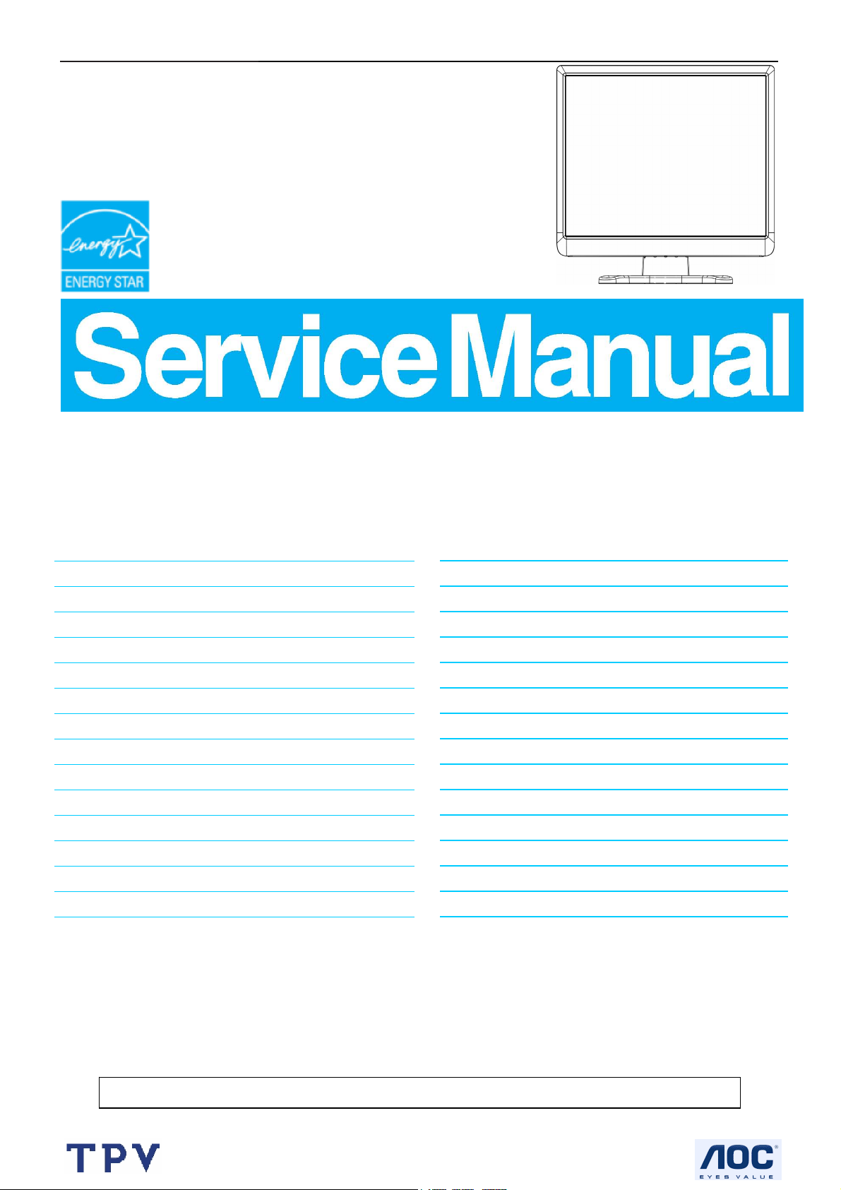
17" LCD Color Monitor AOC 177S
Service
Service
Service
Horizontal Frequency
30-80 kHz
TABLE OF CONTENTS
Description Page Description Page
Table Of Contents.......…….................……...........…........1
Revision List.…........................………................……......2
Important Safety Notice.………….…..................……......3
1.Monitor Specification..............................………........4
2.LCD Monitor Description…………………………….......5
3.Operation Instruction…………...............……...........6
3.1.General Instructions...........................…...........6
3.2.Control Button…………….…..............……...............6
3.3 Adjusting the Picture...........................…............7
4.Input/Output Specification............……………............9
4.1.Input Signal Connector............…………….................9
4.2.Factory Preset Display Modes.........................9
4.3.Panel Specification.....…………...………..................10
5.Block Diagram…….…...................…………................12
5.1.Software Flow Chart…………………....….......12
5.2.Electrical Block Diagram…………..…..….......14
6.Schematic……………...............................….....16
6.1 Main Board……………..........................................16
6.2 Power Board....……..............................................21
7.PCB Layout..………….......................................23
7.1.Main Board………........................................23
7.2.Power Board….......................................26
7.3.Key Board…………………....................................28
8.Maintainability……….......................................29
8.1.Equipments and Tools Requirement......................29
8.2.Trouble Shooting…………..............................30
9.White-Balance, Luminance adjustment.................36
10.Monitor Exploded View……………………............37
11.BOM List….....................................................38
12.Different Parts List……………………………………50
SAFETY NOTICE
ANY PERSON ATTEMPTING TO SERVICE THIS CHASSIS MUST FAMILIARIZE HIMSELF WITH THE
CHASSIS AND BE AWARE OF THE NECESSARY SAFETY PRECAUTIONS TO BE USED WHEN SERVICING
ELECTRONIC EQUIPMENT CONTAINING HIGH VOLTAGES.
CAUTION: USE A SEPARATE ISOLATION TRANSFOMER FOR THIS UNIT WHEN SERVICING
1
Page 2
17" LCD Color Monitor AOC 177S
Revision List
Revision Date Revision History TPV Model
A00 April-19-2007 First Version Release T76CM5NQF1ACF
A01 May-18-2007 Add the audio function T76CM5DCF1A2A
2
Page 3
17" LCD Color Monitor AOC 177S
Important Safety Notice
Proper service and repair is important to the safe, reliable operation of all AOC Company Equipment. The service
procedures recommended by AOC and described in this service manual are effective methods of performing service
operations. Some of these service operations require the use of tools specially designed for the purpose. The
special tools should be used when and as recommended.
It is important to note that this manual contains various CAUTIONS and NOTICES which should be carefully read in
order to minimize the risk of personal injury to service personnel. The possibility exists that improper service
methods may damage the equipment. It is also important to understand that these CAUTIONS and NOTICES ARE
NOT EXHAUSTIVE. AOC could not possibly know, evaluate and advise the service trade of all conceivable ways in
which service might be done or of the possible hazardous consequences of each way. Consequently, AOC has not
undertaken any such broad evaluation. Accordingly, a servicer who uses a service procedure or tool which is not
recommended by AOC must first satisfy himself thoroughly that neither his safety nor the safe operation of the
equipment will be jeopardized by the service method selected.
Hereafter throughout this manual, AOC Company will be referred to as AOC.
WARNING
Use of substitute replacement parts, which do not have the same, specified safety characteristics, may create shock,
fire, or other hazards.
Under no circumstances should the original design be modified or altered without written permission from AOC.
AOC assumes no liability, express or implied, arising out of any unauthorized modification of design.
Servicer assumes all liability.
FOR PRODUCTS CONTAINING LASER:
DANGER-Invisible laser radiation when open AVOID DIRECT EXPOSURE TO BEAM.
CAUTION-Use of controls or adjustments or performance of procedures other than those specified herein may
result in hazardous radiation exposure.
CAUTION -The use of optical instruments with this product will increase eye hazard.
TO ENSURE THE CONTINUED RELIABILITY OF THIS PRODUCT, USE ONLY ORIGINAL MANUFACTURER'S
REPLACEMENT PARTS, WHICH ARE LISTED WITH THEIR PART NUMBERS IN THE PARTS LIST SECTION OF
THIS SERVICE MANUAL.
Take care during handling the LCD module with backlight unit
-Must mount the module using mounting holes arranged in four corners.
-Do not press on the panel, edge of the frame strongly or electric shock as this will result in damage to the screen.
-Do not scratch or press on the panel with any sharp objects, such as pencil or pen as this may result in damage to
the panel.
-Protect the module from the ESD as it may damage the electronic circuit (C-MOS).
-Make certain that treatment person’s body is grounded through wristband.
-Do not leave the module in high temperature and in areas of high humidity for a long time.
-Avoid contact with water as it may a short circuit within the module.
-If the surface of panel becomes dirty, please wipe it off with a soft material. (Cleaning with a dirty or rough cloth may
damage the panel.)
3
Page 4
17" LCD Color Monitor AOC 177S
1. Monitor Specifications
Items Description
Driving system TFT Color LCD
Type CLAA170EA07P
Size 43.2cm (17.0")
Pixel pitch 0.264mm (H) x 0.264mm (V)
LCD Panel
Input
Power Consumption
Viewable angle(CR≥10)
Response time (type) 5 ms
Display Color 16.2M
Contrast Ratio 700:1
White Luminance 300cd/m
Sync. Type H/V TTL
Input Connector D-Sub 15pin
Input Video Signal Analog:0.7Vp-p(standard),75 OHM, Positive
H-Frequency 30kHz – 80kHz
V-Frequency 55-75Hz
ON Mode ≤37W
OFF Mode
160°(H) 160°(V)
2
≤1W
Dot Clock 135MHz
Max. Resolution 1280 x 1024
Plug & Play VESA DDC2BTM
Power Source 100~240VAC,47~63Hz
Maximum Screen Size
Dimensions 384 mm (H) x375.5 mm (W) x209.6 mm (D)
Weight Monitor only: 3.7 kg
Environmental
Considerations
Horizontal : 338mm
Vertical: 270mm
Operating Temp: 5°C to 35°C
Storage Temp: -20°C to 60°C
Operating Humidity: 10% to 85%
4
Page 5
17" LCD Color Monitor AOC 177S
(
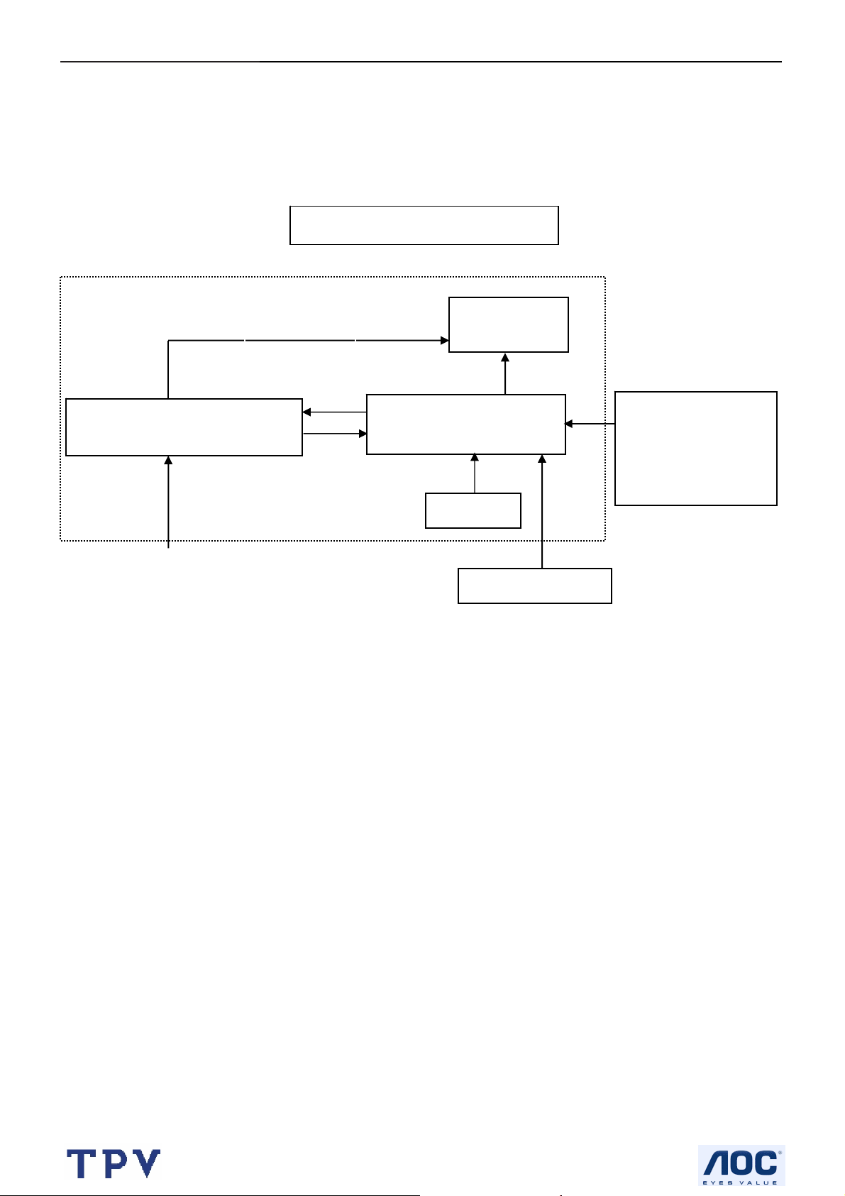
2. LCD Monitor Description
The LCD monitor will contain a main board, power board and a key board which house the flat panel control logic,
brightness control logic and DDC.
The power board will provide AC to DC Inverter voltage to drive the backlight of panel and the main board chips
each voltage.
Monitor Block Diagram
Power board
Include: adapter, inverter)
AC-IN
100V-240V
CCFL Drive.
Flat Panel and
CCFL backlight
Main Board
Key board
HOST Computer
RS232 Connector
For white balance
adjustment in factory
mode
Video signal, DDC
5
Page 6
17" LCD Color Monitor AOC 177S
3. Operating Instructions
3.1 General Instructions
Press the power button to turn the monitor on or off. The control buttons are located in the front of the monitor.
By changing these settings, the picture can be adjusted to your personal preferences.
The power cord should be connected.
-
Connect the video cable from the monitor to the video card.
-
Press the power button to turn on the monitor, the power indicator will light up.
-
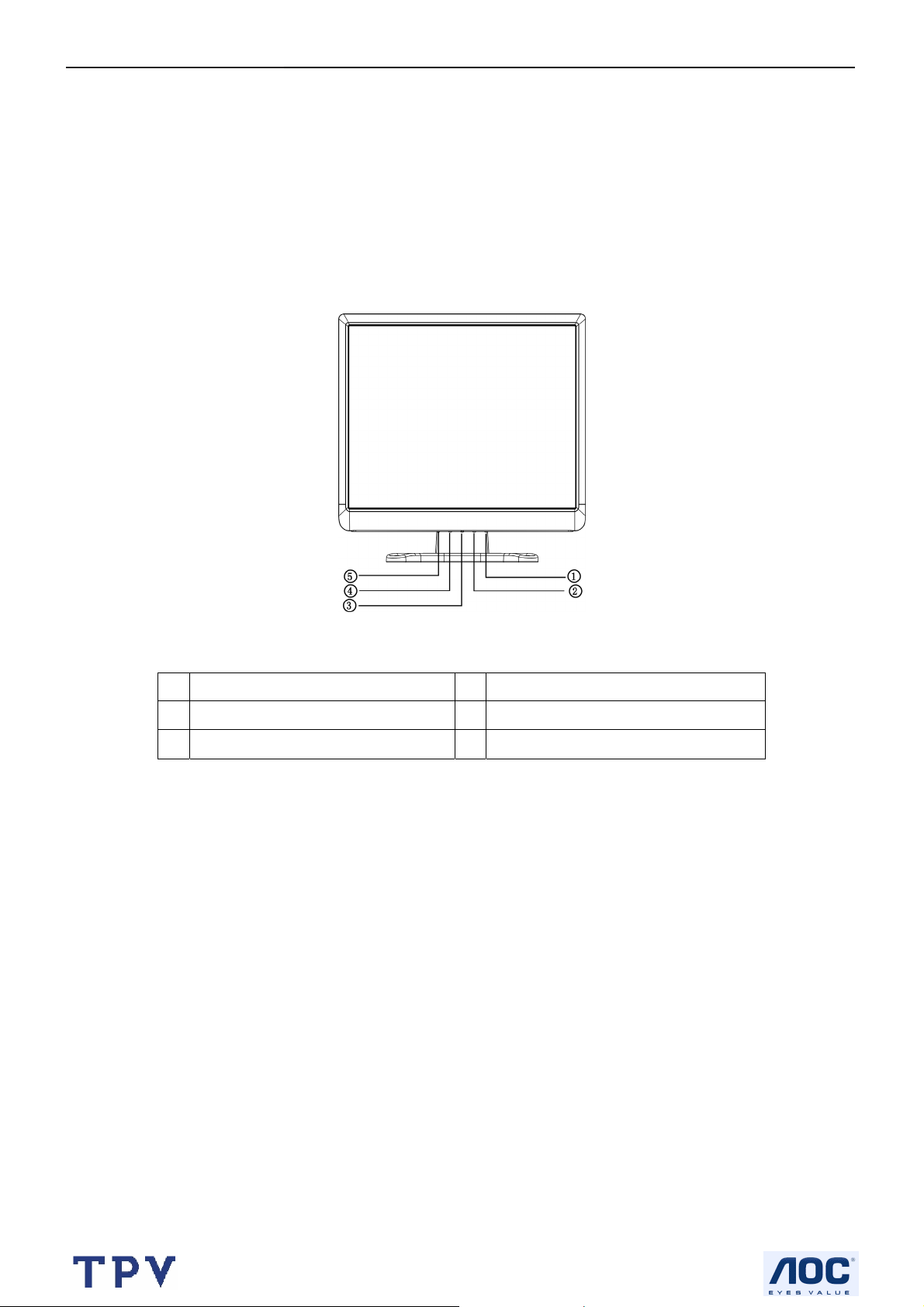
3.2 Control Button
External Controls
1. Contrast 2. Brightness
3. Power Button/ LED 4. MENU / ENTER
5. Auto Adjust button / Exit
• Power Button:
Press this button to turn the monitor ON or OFF.
• Power Indicator:
Green — Power On mode.
Orange — off mode.
• MENU / ENTER:
Activate OSD menu when OSD is OFF or activate/de-activate adjustment function when OSD is ON or Exit OSD
menu when in Brightness /Contrast Adjust OSD status.
• Brightness:
Adjust brightness or functions adjust.
• Contrast:
Adjust contrast or functions adjust.
• Auto Adjust button / Exit:
1. When OSD menu is in active status, this button will act as EXIT-KEY (EXIT OSD menu).
2. When OSD menu is in off status, press this button for 2 seconds to activate the Auto Adjustment function.
The Auto Adjustment function is used to set the HPos, VPos, Clock and Focus.
6
Page 7
17" LCD Color Monitor AOC 177S
3.3 Adjusting the Picture
Adjustment steps:
1. Press the MENU-button to activate the OSD window.
2. Press < or > to select the desired function.
3. Press the MENU-button to select the function that you want to adjust.
4. Press < or > to change the settings of the current function.
5. To exit and save, select the exit function, or leave the monitor alone for 10 seconds. If you want to adjust any
other function, repeat steps 2-4.
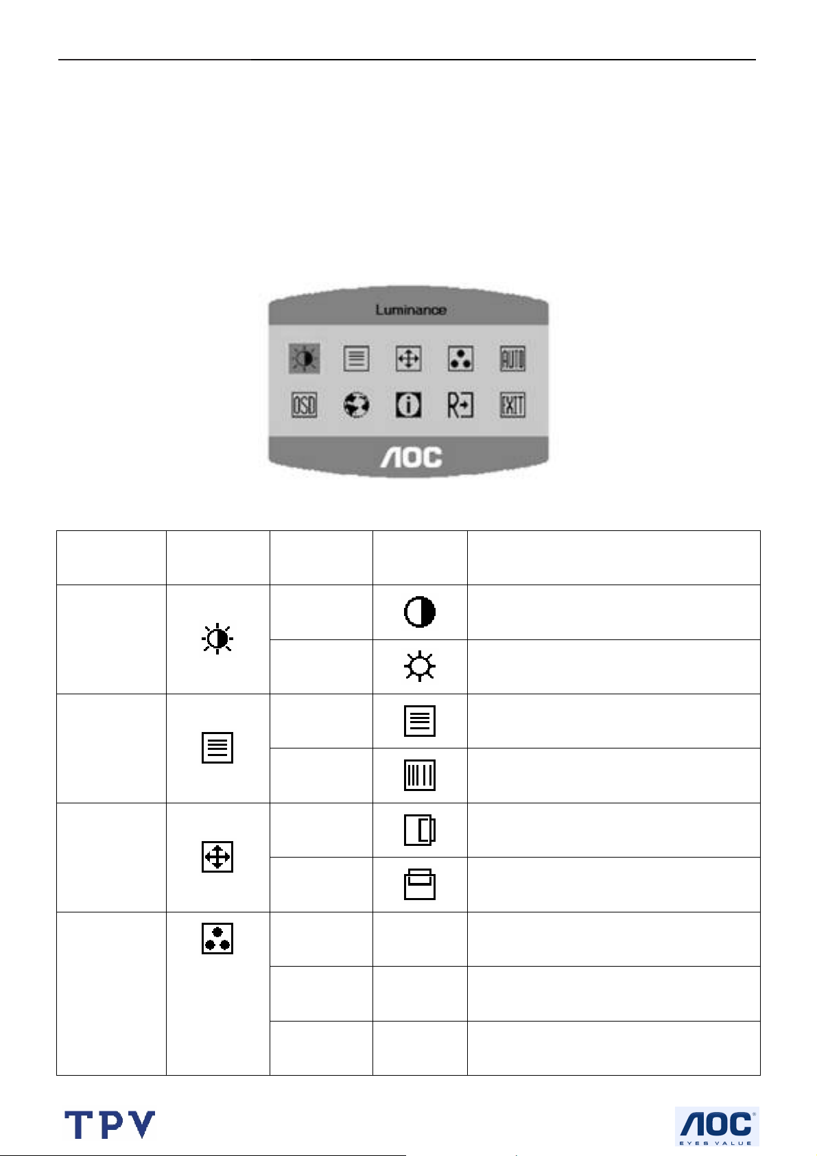
OSD TABLE:
Main Menu Item
Luminance
Image Setup
Image Position
Color Temp.
Main Menu
Icon
Sub Menu
Sub Menu Item
Contrast
Brightness
Focus
Clock
H. Position
V. Position
Warm N/A
Icon
Description
Adjust Picture Phase to reduce Horizontal-Line
Adjust picture Clock to reduce Vertical-Line
Adjust the horizontal position of the picture.
Contrast from Digital-register.
Backlight Adjustment
noise
noise.
Adjust the vertical position of the picture.
Recall Warm Color Temperature from
EEPROM.
Cool N/A Recall Cool Color Temperature from EEPROM.
sRGB N/A
7
Recall sRGB Color Temperature from
EEPROM.
Page 8
17" LCD Color Monitor AOC 177S
User / Blue
Input Select
OSD Setup
User / Red
User / Green
Yes
N/A
No N/A
H. Position
V. Position
OSD Timeout
Red Gain from Digital-register.
Green Gain Digital-register.
Blue Gain from Digital-register.
Auto Adjust the H/V Position, Focus and Clock
of picture.
Do not execute Auto Config, return to main
menu.
Adjust the horizontal position of the OSD.
Adjust the vertical position of the OSD.
Adjust the OSD timeout.
Language
Information
Reset
Exit
Language N/A Set OSD display language that you like..
Show the resolution, H/V frequency and input
Information N/A
port of current input timing.
Clear each old status of Auto-configuration and
Yes N /A
set the color temperature to Cool.
No N/A Do not execute reset, return to main menu.
N/A N/A Exit OSD
8
Page 9
17" LCD Color Monitor AOC 177S
4. Input/Output Specification
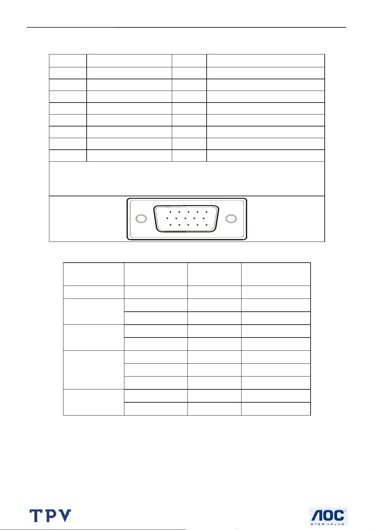
4.1 Input Signal Connector
Pin No. Description Pin No. Description
1. Red Video 9. +5V
2. Green Video 10. Detect Cable
3. Blue Video 11. TXD
4. RXD 12. DDC-Serial Data
5. Ground 13. H-Sync
6. Red Ground 14. V-Sync
7. Green Ground 15. DDC-Serial Clock
8. Blue Ground
VGA connector layout
4.2 Factory Preset Display Modes
Standard
Dos-mode 720 x 400 31.47kHz 70.0Hz
VGA
SVGA
XGA
640 × 480 31.47kHz 60.0Hz
640 × 480 37.50kHz 75.0Hz
800 × 600 37.879kHz 60.0Hz
800 × 600 46.875kHz 75.0Hz
1024 × 768 48.363kHz 60.0Hz
1024 × 768 56.476kHz 70.0Hz
1024 × 768 60.021kHz 75.0Hz
15
6
11 15
10
Horizontal
Resolution
Frequency
Vertical
Frequency
SXGA
1280 × 1024 64.000kHz 60.0Hz
1280 × 1024 80.000kHz 75.0Hz
9
Page 10
17" LCD Color Monitor AOC 177S
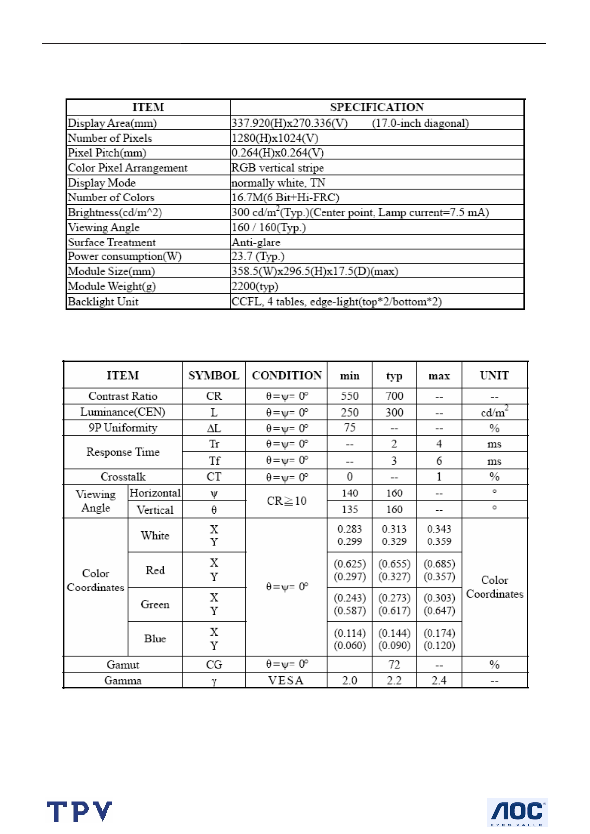
4.3 Panel Specification
4.3.1 Display Characteristics
4.3.2 Optical Characteristics
10
Page 11
17" LCD Color Monitor AOC 177S
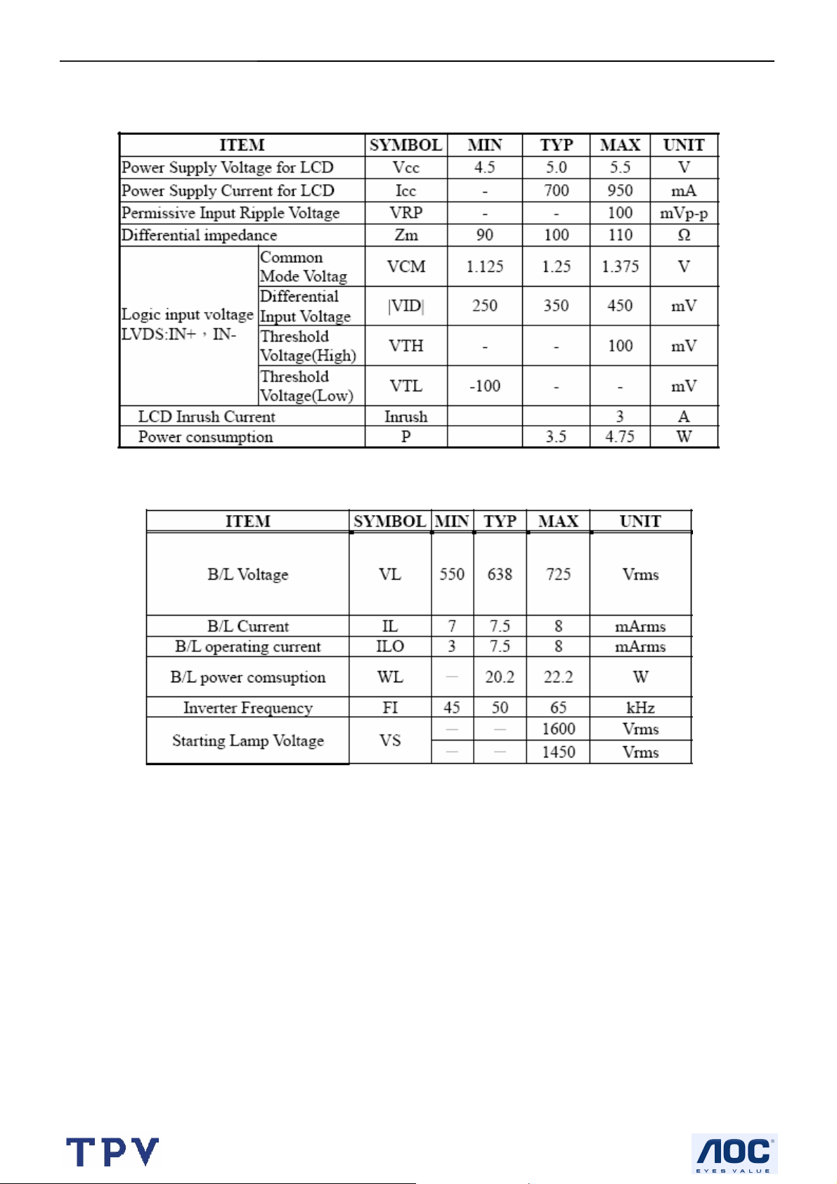
4.3.3 Electrical Characteristics
TFT LCD Module:
Back Light Unit:
11
Page 12
17" LCD Color Monitor AOC 177S
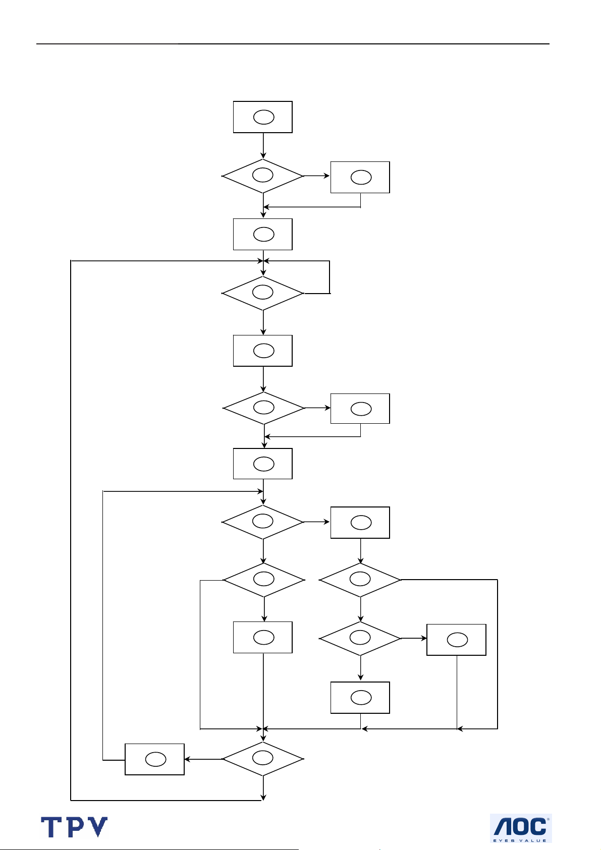
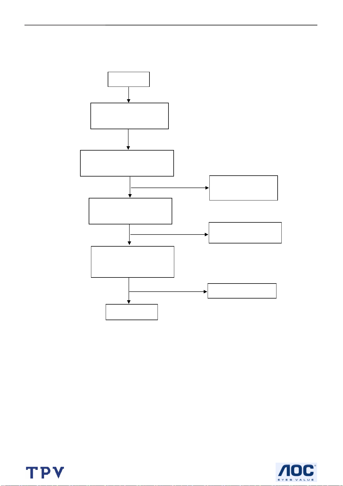
5. Block Diagram
5.1 Software Flow Chat
1
2
N
4
5
Y
6
7
Y
Y
N
N
3
18
9
10
Y
N
N
12
Y
14
19
N
11
13
15
17
N
Y
N
Y
16
Y
12
Page 13
17" LCD Color Monitor AOC 177S
1) MCU initialize.
2) Is the EPROM blank?
3) Program the EPROM by default values.
4) Get the PWM value of brightness from EPROM.
5) Is the power key pressed?
6) Clear all global flags.
7) Are the AUTO and SELECT keys pressed?
8) Enter factory mode.
9) Save the power key status into EPROM.
Turn on the LED and set it to green color.
Scalar initializes.
10) In standby mode?
11) Update the lifetime of back light.
12) Check the analog port, are there any signals coming?
13) Does the scalar send out an interrupt request?
14) Wake up the scalar.
15) Are there any signals coming from analog port?
16) Display "No connection Check Signal Cable" message. And go into standby mode after the message
disappear.
17) Program the scalar to be able to show the coming mode.
18) Process the OSD display.
19) Read the keyboard. Is the power key pressed?
13
Page 14
17" LCD Color Monitor AOC 177S
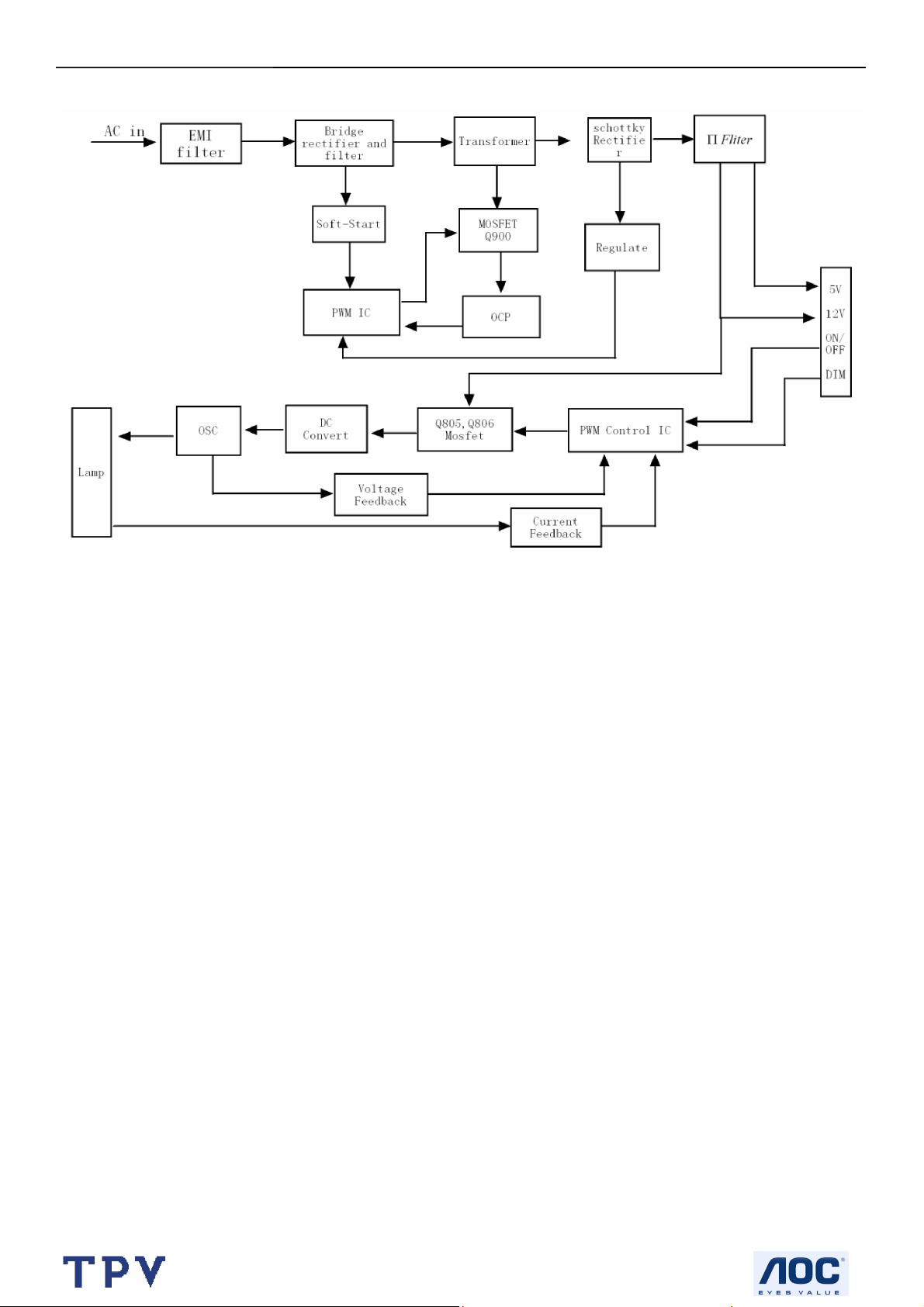
5.2 Electric Block Diagram
5.2.1 Main Board
Crystal (14.318MHz)
(X401)
LCD interface
(CN101)
EEPROM
PM25LV512
(U402)
Scalar TSUM16AK
(Include MCU, ADC, OSD)
(U401)
H sync
V sync
RGB
D-Sub
Connector
(CN405)
EEPROM
M24C02-WMN6TP
(U404)
14
Page 15
17" LCD Color Monitor AOC 177S
5.2.2 Power Board
15
Page 16
17" LCD Color Monitor AOC 177S
6. Schematic
6.1 Main Board
TSUM56AK SCHEMATIC
B3
+5V
+5V
GNDR
GNDG
GNDB
HSYNC
VSYN C
DDCA_SDA
DDCA_SCL
DET_VGA
DDC_WP
CLK+
DDCD_SDA
DDCD_SCL
DET_DVI
RIN
GIN
SOG
BIN
CLK-
R+
RG+
G-
B+
B-
XGA/SXGA
B4
RIN
GNDR
GIN
GNDG
SOG
BIN
GNDB
HSYNC
VSYN C
DDCA_SDA
DDCA_SCL
DET_VGA
DDC_WP
R+
RG+
GB+
B-
CLK+
CLKDDCD_SDA
DDCD_SCL
DET_DVI
3.INPUT
LVDS OUTPUT
VCC3.3
VCC1.8 +5 V
VCC1.8
Vcc3.3
+5V
+12V
+12V
VCC3.3
VCC5V
B5
PA[0.. 7]
PA[8.. 13]
PA[14.. 19]
+12V
PC5V
+3V3
VCC1.8
+5V
B2
+12V
+3V3
VCC1.8
+5V
VCC5V
VCC3.3
on_BACKLIGH T
on_Panel
on_PANEL_12V
VCTRLPC5V
Adj_BACKLIGH T
VLCD
VLCD_12V
VLCD
VLCD_12V
on_BACKLIGH T
on_Panel
on_PANEL_12V
VCTRL
Adj_BACKLIGH T
4.SCALER
PB[0.. 5]
PB[6.. 11]
PB[12.. 23]
GPO[0.. 4]
ESP
OSP
PA[0.. 7]
PA[8.. 13]
PA[14.. 19]
PB[0.. 5]
PB[6.. 11]
PB[12.. 23]
GPO[0.. 4]
2.POW ER
PA[0.. 7]
PA[8.. 13]
PA[14.. 19]
PB[0.. 5]
PB[6.. 11]
PB[12.. 23]
GPO[0.. 4]
ESP
OSP
VLCD
VLCD_12V
VLCD
VLCD_12V
5.PANEL INTERFACE
Tit le
Size Document Num ber Rev
B
Date: Sheet
715G1558.DSN
TOP
of
26Saturday , Nov ember 12, 2005
B
16
Page 17

17" LCD Color Monitor AOC 177S
+5V3,4
Adj_BACKLIGHT
4
C706
0.1uF
U701
+5V
C701
NC
C707
+
100uF/25V
C709
0.1uF
3 2
+12V
+5V
C710
+
100uF/25V
SOT-223
NC/LT1117-18
VI VO
VO
GND
1
BL_ADJ(DC)
0V ~ 3.3V
0V ~ 5V
BL_ADJ
P W M
D C
+12V 4
GND
1
GND
3
5
+12V
GND
7
+5V
9
GND
11
R706
NC
R707
4.7K 1/16W
R31
47
4K7
CN701
CONN
4
100uF/25V
R31
4.7K
4.7K
VCC5V
C703
C32
N.C
1uF
2
4
6
8
10
12
R701
Q701
PMBS3904
C51
1UF
1UF
BL_ON
BL_ADJ
+12V
GND
+5V
GND
1K 1/16W
R705
+
R32
0
X
4.7K 1/16W
R29
X
1K
C708
C704
NC
R33
X
4.7K
1uF
C711
0.1uF
+3V3
Q4
X
MMBT3904
R708
10K 1/16W
+5V
Q703
PMBS3904
H1
+3V3
R710 NC
R712 4.7K 1/ 16W
D704(SSM12L) Vf=0.38V and If=1 A.
So when system power on, the
system loading is about 400mA
(3.3V is about 200mA and 1.8V is
about 200mA), So D35 changed
from 1N4148(or BAT42) to
SSM12L(schottky diode).
P.S: The 1N4148 Vf=0.7V~1V can 't meet
LDO spec. The BAT42, Vf is OK but the
If=200mA(forward current) can not
meet current spec.
678
9
678
5
9
4
123
123
+5V
R711
10K 1/16W
5
4
TP
on_BACKLIGHT 4
H2
9
9
123
123
678
678
5
4
H3
678
5
9
5
4
TP
9
123
123
678
5
4
4
TP
D701
C
1N4148
B
Q702
D702
CHT2907
E
3
C713
0.1uF
PC5V
+
1
R709
0 1/16W
D703
BAT54C
1N4148
R704
100 1/16W
PC5V 3
TO-263
U702
3
VIN
1
ADJ
AIC1084-33PM
Recommond to used "Blue" part s circuit
for VCC1.8V if you want to su ppoert DDC
function when system power off
2
VOUT
4
VOUT
R720 0 1/16W
C705
1uF/16V
+5V
+5V3,4
R732
+5V
10 1/16W
+5V3,4
SMAL140
2
D704
VCTRL 4
R702
51 1/16W
VCC1.8
C702
+
4.7uF/16V
R703
2K 1/16W
VCC3.3
R713
C712
+
NC
100uF/25V
VCC1.8 4
VCC3.3 4
VCC3.3
VCC3.3 4
C714
0.1uF
+3V3
R714
R717
R716
R733
R734
NC
10K 1/16W
on_Panel4
4.7K 1/16W
NC
R735
C721
0.1uF
Q708
PMBS3904
10K 1/16W
R725
4.7K 1/16W
C718
0.1uF
10K 1/16W
+5V
R723 51K 1/16W
Q706
PMBS3904
+3V3
VLCD
VLCD 5
+5V
R721
0 1/16W
R727
10K 1/16W
+3V3
R722
NC
on_Panel_12V4
R715
NC
C715
0.1uF
Q704
AO3401L
+
10uF/16V
C717
For RSDS and Panel VCC=12V
+5V
R736
NC/10K
R737 NC /4K7
C722
NC/0. 1uF
R718
NC/10K
R726 NC /4K7
Q709
NC/PMBS3904
NC/0. 1uF
+5V
+12V
R729
NC/10K
Q707
C720
R719
NC/10K
R724 51K
C716
0.1uF
NC/PMBS3904
VLCD_12V
Q705
AO3401L
+
C719
NC/10uF /16V
VLCD_12V 5
R728
NC/4K7
+5V
+12V
R730
R731
NC
0 1/16W
Titl e
Size Doc ument Number Rev
Custom
Date: Sheet
Power
715G1558.DSN
36Saturday , Novem ber 12, 2005
B
of
17
Page 18

17" LCD Color Monitor AOC 177S
CN405
CN406
RGB GND
HSYNC
VSYN C
SYNC GND
DDC SCL
DDC SDA
1/3shield
2/4shield
0/5shield
clk shield
DAT0+
DAT0-
DAT1+
DAT1-
DAT2+
DAT2-
DAT3+
DAT3-
DAT4+
DAT4-
DAT5+
DAT5-
JACK DVI
1716
11
12
13
14
15
HSI
VSI
D408
MLL5232B 5.6V
25
R
26
G
27
B
29
28
8
15
6
7
14
+5V
16
HPD
11
3
19
22
18
17
10
9
2
1
13
12
5
4
21
20
23
clk+
24
clk-
DB15
RED+
1
RED-
6
GREEN+
2
GREEN-
7
BLUE+
3
BLUE-
8
4
9
VGA_CON
5
10
MLL5232B 5.6V
SCL_DVI
SDA_DVI
DVI5V
HPD
DAT0+
DAT0DAT1+
DAT1DAT2+
DAT2-
DCLK+
DCLK-
PC5V
PC5V
D406
FB409 120 OHM
D409
MLL5232B 5.6V
R472
NC
3
D417
BAV99
C447
1
2
0.1uF
3
D403
BAV99
C439 0.1uF
2
VCC5V
R471
10K 1/16W
R458 100 1/16W
D426
LL5232B 5.6V 5%
3
D418
BAV99
C448
1
2
0.1uF
1
2
3
C440 0.1uF
2
3
D419
BAV99
C449
1
0.1uF
D404
BAV99
C441 0.1uF
2
1
R448
2.2K 1/16W
D414
LL5232B 5.6V 5%
3
D420
BAV99
C450
1
2
0.1uF
FB410 0 1/16W
FB411 0 1/16W
FB412 0 1/16W
3
D405
BAV99
1
DET_DVI 4
3
C451
2
0.1uF
R438
75 1/16W
ESD_5V
R446 1K 1/16W
C442
R449
33pF
D415
LL5232B 5.6V 5%
D421
BAV99
2.2K 1/16W
R455 100 1/16W
R456 100 1/16W
1
3
D422
BAV99
C452
1
2
0.1uF
R439
75 1/16W
R447 1K 1/16W
C443
220pF
D416
LL5232B 5.6V 5%
3
D423
BAV99
C453
1
2
0.1uF
R440
75 1/16W
D411
MLL5232B 5.6V
DVI5V
C445
0.1uF
R462 10 1/16W
R463 10 1/16W
R464 10 1/16W
R465 10 1/16W
R466 10 1/16W
R467 10 1/16W
R468 10 1/16W
R469 10 1/16W
3
D424
BAV99
C454
1
2
0.1uF
R434 56 1/16W
R435 56 1/16W
R436 56 1/16W
R437 470 1/16W
R441 100 1/16W
R442 100 1/16W
R443 100 1/16W
+5V
R444
10K 1/16W
D410
MLL5232B 5.6V
D412
MLL5232B 5.6V
R457
10K 1/16W
+5V 2, 4
R445 100 1/16W
ESD_5V
B+ 4
B- 4
G+ 4
G- 4
R+ 4
R- 4
CLK+ 4
CLK- 4
C432 0.047uF
C433 0.047uF
C434 0.047uF
C435 0.047uF
C436 0.047uF
C437 0.047uF
C438 0.047uF
SCL_VGA
SDA_VGA
+5V
R470
D425
1 2
DDCA_SDA4
DDCA_SCL4
DDCD_SDA4
DDCD_SCL4
1K 1/16W
RLZ36B
RIN 4
GIN 4
BIN 4
SOG 4
GNDR 4
GNDG 4
GNDB 4
DET_VGA 4
HSYNC 4
VSYN C 4
R450
10K 1/16W
R453 100 1/16W
R454 100 1/16W
10K 1/16W
R459
+5V
PC5V
1
2
D407
BAV70
R451
10K 1/16W
10K 1/16W
3
R452
+5V
R460
R461
10K 1/16W
10K 1/16W
Tit le
Size Document Num ber Rev
Date: Sheet
U404
8
7
6
DVI5V
1
2
3
R473
NC
VCC
WP
SCL
M24C02
D413
BAV70
U405
8
7
6
M24C02
VCC
WP
SCL
A0
A1
A2
GNDSDA
GNDSDA
C444
1
0.1uF
2
3
45
DDC_WP 4
C446
1
A0
A1
A2
0.1uF
2
3
45
DDC_WP 4
INPUT
B
715G1558.DSN
46Saturday , Nov ember 12, 2005
B
of
18
Page 19

17" LCD Color Monitor AOC 177S
GND
41
C431
1uF/25V
AVDD
60
47
VDDP
67
14
VDDP
AVDD_ADC
GND
GND
GND
OUT-L+
OUT-L-
VDDC
12
97
95
103
115
VDDP
VDDP
VDDP
VDDP
VDDC
CLKAP/LVB3P/ LHSYNC
CLKAN/LVB3M/ LVSYNC
CLKBP/LVBCKP /LCK_ODD
68
117
VCTRL
VDDC
VDDC
NC/LVAC KP/NC
NC/LVACKM/NC
VDD_OTP
RA1P/LVA2P/RA2
RA1N/LVA2M/RA3
RA2P/LVA1P/RA4
RA2N/LVA1M/RA5
RA3P/LVA0P/RA6
RA3N/LVA0M/RA7
GA1P/NC/GA2
GA1N/N C/GA3
GA2P/NC/GA4
GA2N/N C/GA5
GA3P/LVA3P/GA6
GA3N/LVA3M/GA7
BA1P/NC/ BA2
BA1N/NC/BA3
BA2P/NC/ BA4
BA2N/NC/BA5
BA3P/NC/ BA6
BA3N/NC/BA7
RB1P/NC/RB2
RB1N/NC/RB3
RB2P/NC/RB4
RB2N/NC/RB5
RB3P/NC/RB6
RB3N/NC/RB7
GB1P/NC/GB2
GB1N/N C/GB3
GB2P/NC/GB4
GB2N/N C/GB5
GB3P/NC/GB6
GB3N/N C/GB7
CLKBN/LVBCKM/LDE
NC/LVB2P/NC
NC/LVB2M/NC
BB1P/LVB1P/BB2
BB1N/LVB1M/BB3
BB2P/LVB0P/BB4
BB2N/LVB0M/BB5
BB3P/NC/ BB6
BB3N/NC/BB7
GPIO_P22
GPIO_P23
GPIO_P03
GPIO_P16
GPIO_P15
PWM2/GPIO_P24
GPIO_P27/PWM1
GPIO_P16
PWM1/GPIO_P25
GPIO_P17/SAR0
GPIO_P00/SAR1
GPIO_P01/SAR2
GPIO_P02/SAR3
GPIO_P06
GPIO_P07
PWM0/GPIO_P26
GPIO_P13
GPIO_P14
DDCROM_SCL
DDCROM_SDA
FB407
600 OHM
FB408
600 OHM
CN404
2
1
4
3
6
5
8
7
10
9
12
11
14
13
CONN
GPO0
GPO1
GPO2
GPO3
GPO4
GPO5
GPO6
ESP
OSP
11
PA0
107
PA1
108
PA2
109
PA3
110
PA4
111
PA5
112
PA6
113
PA7
114
PA8
98
PA9
99
PA10
100
PA11
101
PA12
105
PA13
106
PA14
89
PA15
90
PA16
91
PA17
92
PA18
93
PA19
94
PB0
9
PB1
10
PB2
15
PB3
16
PB4
17
PB5
18
PB6
2
PB7
3
PB8
5
PB9
6
PB10
7
PB11
8
PB12
118
PB13
119
PB14
120
PB15
121
PB16
122
PB17
123
PB18
124
PB19
125
PB20
126
PB21
127
PB22
128
PB23
1
80
81
88
87
86
85
84
83
82
75
74
26
35
69
78
79
20
21
22
23
24
25
27
28
29
30
31
77
76
+12V
+5V
10K 1/16W
OUT-R+
OUT-R-
ESP
OSP
GPO0
GPO1
GPO2
GPO3
GPO4
R488 NC
R418 100 1/16W
R420 100 1/16W
R411 100 1/16W
R422 4.7K 1/16W
R423 4.7K 1/16W
VCC3.3
R425
R424
10K 1/16W
10K 1/16W
R428 100 1/16W
R429 100 1/16W
+12V 2
+5V 2,3
+5V
R484
R485
10K 1/16W
AUDIO_STBY
AUDIO_MUTE
VCTRL 2
P[0..7]
PA[8..13]
PA[14..19]
PB[0..5]
PB[6..11]
PB[12..23]
GPO[0.. 4]
WP
KEY1
KEY2
POWER
Volume
AUDIO_MUTE
AUDIO_STBY
R426
10K 1/16W
R427 100 1/16W
Option
PA[0..7] 5
PA[8..13] 5
PA[14..19] 5
PB[0..5] 5
PB[6..11] 5
PB[12..23] 5
ESP 5
OSP 5
GPO[0..4] 5
R405
22K 1/16W
R406
10K 1/16W
on_PANEL_12V 2
DET_DVI 3
DET_VGA 3
on_PANEL 2
on_BACKLIGHT 2
adj_BACKLIGH T 2
U403
8
VCC
7
WP
6
SCL
AT24C16N-10SC-2.7
KEY_B
LED_G
KEY_AUTO
KEY_RI GHT
POWER
OUT-L+
OUT-L-
FB401
VCC1.8
VCC3.3
VCC3.32
VCC3.32
+5V 2,3
10K 1/16W
3.9K 1/16W
C430
0.1uF
600 OHM
600 OHM
R474
4.7uF/16V
FB403
R413
VCC3.3
D402
1 2
C403
RLZ36B
VDDC
+
VCC3.3
VCC3.3
3.9K 1/16W
C404
0.1uF
10uF/16V
VCC3.3
C408
R475
C405
0.1uF
VDDP
+
FB404
600 OHM
FB406
600 OHM
R414
240 1/16W
Q401
PMBS3906
R421 0 1/16W
C406
0.1uF
C409
C411
C410
0.1uF
0.1uF
0.1uF
VDVI
C414
C415
0.1uF
0.1uF
VMPLL
C419
C420
0.1uF
0.1uF
10K 1/16W
LED_G
R476 1K 1/16W
R477 1K 1/16W
Title
Size Docum ent Number Rev
C
Date: Sheet
VCC1.82
VCC3.32
DDC_WP 3
Q402
PMBS3904
C422
0.1uF
C425
0.1uF
1
A0
2
A1
3
A2
45
GNDSDA
CN403
1
3
5
7
9
11
13
15
CONN
VCC3.3
R481
R482
NC
NC
C
Q405
B
NC
E
R483
NC
KEY2
KEY1
LED_G
LED_A
POWER
C426
C427
0.1uF
0.1uF
KEY_A
2
LED_A
4
KEY_MENU
6
KEY_LEFT
8
10
KEY_C
12
OUT-R+
14
OUT-R-
16
GND
+5V
KEY A
C428
0.1uF
R412
C616
NC
C429
0.1uF
10K 1/16W
R417 20K 1/16W
C424 0.1uF
D401
RLZ36B
1 2
VCC3.32
C412
0.1uF
R408
C413
0.1uF
VCC3.32
VCC3.3
R478 1K 1/16W
R479 1K 1/16W
VCC3.3
FB402
600 OHM
VCC3.3
R409
75 1/16W
Q403
PMBS3906
R419 0 1/16W
R480 1.5K 1/16W
SCALER
715G1558.DSN
AVDD
FB405
600 OHM
LED_A
KEY_AUTO
KEY_RI GHT
KEY_MENU
KEY_LEFT
C407
0.1uF
VPLL
C416
0.1uF
KEY_A
KEY_B
KEY_C
B
of
56Saturday, November 12, 2005
VMPLL
VPLL
VDVI
44
50
AVDD_DVI
AVDD_DVI
AVDD_MPLL
AVDD_MPLL
TSUM57AK/56AK
R432 10K 1/16W
52344
AVDD_PLL
RSDS/LVDS/TTL
GND
GND
3896116
13
DDCA_SDA3
DDCA_SCL3
VCC3.3
+
C418
10uF/16V NC
R404
10K 1/16W NC
+5V
Res e t
Circuit
C417
0.1uF
10K 1/16W
U406
1
VCC3.3
R490
R489
10K 1/16W
VCC3.3
R486
NC
R487
10K 1/16W
23
RSTVCC
GND
ASM810MEURF-T
Volume
RIN3
GNDR3
GIN3
GNDG3
SOG3
BIN3
GNDB3
HSYNC3
VSYNC3
CLK+3
CLK-3
DDCD_SDA3
DDCD_SCL3
AVDD
U402
8
VDD
7
HOLD#
3
WP#
4 5
VSS SDI
WP
SST25VF010-20-4C-SAE
VCC3.3
R407 NC
R410 NC
10K 1/16W
R431 NC
R433 4.7K 1/16W
R+3
R-3
G+3
G-3
B+3
B-3
R403 390 1%
SDO
CE#
SCK
C421 22pF
14.318MHz
C423 22pF
R415
U401
59
RIN0P
58
RIN0N
56
GIN0P
55
GIN0N
57
SOGIN0
54
BIN0P
53
BIN0N
63
HSYNC0
64
VSYNC 0
65
DDCA_SDA
66
DDCA_SCL
39
RX2P
40
RX2N
42
RX1P
43
RX1N
45
RX0P
46
RX0N
48
RXCKP
49
RXCKN
36
DDCD_SDA
37
DDCD_SCL
51
REXT
62
REFP
C401
61
0.1uF
REFM
70
2
SDO
71
1
SCZ
72
6
SCK
73
SDI
19
RST
32
XIN
X401
33
XOU T
102
MODE [0 ]
104
MODE [1 ]
R416
10K 1/16W
+5V
R430
1K 1/16W
Q404
PMBS3904
19
Page 20

17" LCD Color Monitor AOC 177S
PB[0..5]4
PB[6..11]4
PB[12..23]4
OSP4
ESP4
VLCD2
VLCD_12V
VLCD_12V2
CN8
CN9
R88
RP1
X
X
V
V
V
X
8
7
6
C101
NC
PA[0..7]
C102
NC
PB[12.. 23]
C103
NC
PA0
PA1
PA2
PA3
PA4
PA5
PA6
PA7
PA12
PA13
PB12
PB13
PB14
PB15
PB16
PB17
PB18
PB19
PB20
PB21
C104
NC
LVDS Panel
RSDS Panel
C105
NC
LVACKP
LVACKM
LVA2P
LVA2M
LVA1P
LVA1M
LVA0P
LVA0M
LVA3P
LVA3M
LVB3P
LVB3M
LVBCKP
LVBCKM
LVB2P
LVB2M
LVB1P
LVB1M
LVB0P
LVB0M
GPOO0
GPOO1
GPOO2
GPOO3
GPOO4
CN7
X
V
PA[0.. 7]4
PA[8.. 13]4
PA[14..19]4
GPO[0.. 4]4
PA[0.. 7]
PA[8.. 13]
GPO[0.. 4]
PA[0..7]4
PA2
RA1P
PA3
RA1N
RA2P FB1N
PA4
PA5
RA2N
PA6
RA3P
PA7
RA3N
PA8
GA1P
PA9
GA1N
PA10
GA2P
GA2N
PA11
PA12
GA3P
PA13
GA3N
PA14
PA15
PA16
PA17
PA18
PA19
PB12
PB13
GPO0
GPO1
GPO2
GPO3
GPO4
PB[12..23]4
BA1P
BA1N
BA2P
BA2N
BA3P
BA3N
CLKAP
CLKAN
RP101 NC
1
2
3
4 5
R110 N C
PB[0..5]
PB0
RB1P
PB1
RB1N
PB2
RB2P
PB3
RB2N
PB4
RB3P
PB5
PB6
PB7
PB8
PB9
PB10
PB11
PB14
PB15
PB18
PB19
PB20
PB21
PB22
PB23
R101 NC /0
R102 NC/0
Table 1
AU 17
QDI 17
CPT 17
INNOLUX 15
HannStar 15
CPT 15
LG 15
Innolux 17"
RB3N
GB1P
GB1N
GB2P
GB2N
GB3P
GB3N
CLKBP
CLKBN
BB1P
BB1N
BB2P
BB2N
BB3P
BB3N
C106
NC
PB[6..11]
PB[12..23]
OSP
ESP
VLCD
Table 1
R91
R89
X
X
X
X
V
V
V
V
RA3N
RA3P
RA2N
RA2P
RA1N
RA1P
GA3N
GA3P
GA2N
GA2P
GA1N
GA1P
CLKAN
CLKAP
BA3N
BA3P
BA2N
BA2P
BA1N
BA1P
GPOO1
GPOO0
C107
GPOO3
GPOO2
GPOO4
NC
R103 NC
R104 NC LVB3M
R105 NC
R106 NC
R107 NC
R108 NC
R109 NC
R93
R92
R90
3.3V
3.3V
3.3V
3.3V
NC
0R
0R
0R
0R
NC
5V
0R
NC
12V
0R
NC
3.3V
0R
NC
3.3V
NC
0R
3.3V
NC
0R
3.3V
0R
NC
FB0N
FB0P
FB1P
FB2N
FB2P
FG0N
FG0P
FG1N
FG1P
FG2N
FG2P
FCLKN
FCLKP
FR0N
FR0P
FR1N
FR1P
FR2N
FR2P
STH
LP
POL
STV2
CLKV
STV1
OE
R94
5V
0R
NC
NC
NC
NC
3.3V
0R
CN102
1
2
3
4
5
6
7
8
9
10
11
12
13
14
15
16
17
18
19
20
21
22
23
24
25
26
27
28
29
30
31
32
33
34
35
36
37
38
39
40
41
42
43
44
45
46
47
48
49
50
IL-FHR -B50S-HF (JAE)
R95
R96
5V
0R
NC
12V
0R
NC
NC
NC
12V
0R
NC
NC
NC
3.3V
0R
NC
CN103
RXO0RXO1RXO2RXOCRXO3RXE0RXE1RXE2RXECRXE3-
VLCD
1
2
3
4
5
6
7
8
9
10
11
12
13
14
15
16
17
18
19
20
21
22
23
24
25
26
27
28
29
30
IL-FH R-B30S-HF (JAE)
CN101
2
1
4
3
6
5
8
7
10
9
CONN
VLCD 2
12
14
16
18
20
22
24
11
13
15
17
19
21
23
RXO0+
RXO1+
RXO2+
RXOC+
RXO3+
RXE0+
RXE1+
RXE2+
RXEC+
RXE3+
LVB0P
LVB1P
LVB2P
LVBCKP
LVB3P
LVA0P
LVA1P
LVA2P
LVACKP
LVA3P
B0N
RB3N
B0P
RB3P
B1N
RB2N
B1P
RB2P
B2N
RB1N
B2P
RB1P
GB3N
BG0N
GB3P
BG0P
GB2N
BG1N
GB2P
BG1P
GB1N
BG2N
GB1P
BG2P
BCLKN
CLKBN
CLKBP
BCLKP
BR0N
BB3N
BB3P
BR0P
BB2N
BR1N
BB2N
BB2P
BR1P
BB1N
BR2N
BR2P
BB1P
LVB0M
LVB1M
LVB2M
LVBCKM
LVA0M
LVA1M
LVA2M
LVACKM
LVA3M
R97
NC
12V
0R
NC
NC
NC
NC
Tit le
Size Document Number Rev
B
Date: Sheet
PANEL INTERFACE
715G1558.DSN
66Saturday , Novem ber 12, 2005
B
of
20
Page 21

17" LCD Color Monitor AOC 177S
6.2 Power Board
R951
C901
1000pF
330KΩ 1/4W
R900
2
1
+
-
4
L902
142
7.0mH
L901
124
L
C909
0.47uF
330KΩ 1/4W
R901
330KΩ 1/4W
3
CN901
SOCKET
47Ω 1/4W
BD1
2KBP08M
IC921
4
5
6
4
6
1
3
0.0033uF /250V
43
T901
POWER X'FMR
C905
C900
0.0022UF
12
3
C907
+
100uF/450V
3
C902
NR901
NTCR
F901
FUSE
1000pF
100KΩ 1/8W
R911
3
R902
12
R911
10KΩ 1/4W
HV
NC
RT
COMPCSGNDOUT
123
1500pF/1K V
BA159GPT
0.1uF
C912
678
U901
LD7575PS
VCC
4 5
C913
220pF
C914
470pF/25V
R913
1KΩ 1/8W
C916
0.1uF
LL4148WP
D910
10Ω 1/4W
R912
22uF/50V
C911
+
D901
UF4003PT
R915
10KΩ 1/8W
C910
D900
R909
100KΩ 2W
R910
7.5Ω 1/ 4W
Q900
STP10NK70ZF P
R916
0.43Ω 2W
PC123X2YF ZOF
IC902
KIA431A-AT/P
47Ω 1/4W
9
7
11
10
8
12
R922
470Ω 1/4W
R952
47Ω 1/4W
R925
1KΩ 1/8W
R928
1KΩ 1/8W
C928
0.1uF
47Ω 1/4W
R954
R955
0.001uF/ 500V
D920
3
SBT150-10LST
2
1
31DQ06FC
D922
C921 0.001 uF/500V
C920
IND CHOKE 3. 5uH+-10% DADONG
C926
1000uF/16V
ZD921
RLZ13B
D915
C922
680uF/25V
1 2
+
ZD922
RLZ5.1B
D916
1N4148W
+
C924
680uF/25V
IND CHOKE 3.5uH+-10% DADONG
+
1 2
1N4148W
R927
100Ω 1/8W
+
C923
680uF/25V
L922
C932
+
470uF/16V
L921
R923
10KΩ 1/8W
3.6KΩ 1/8W
C929
0.1uF
100Ω 1/8W
R930
+
+
C925
470uF/25V
ZD920
PTZ9.1B
C927
470uF/16 V
R924
1 2
R929
2.4KΩ 1/ 8W
R931
10KΩ 1/4W
R956
33KΩ 1/8W
ON/OF F
0Ω 1/4W
F902
C931
0.1uF
DIM
C930
0.1uF
+12V
+5V
CN902CONNECTOR
10
9
8
7
6
5
4
3
2
1
21
Tit le
Size Document Number Rev
B
Date: Sheet
AOC 17F
2、Power
G1823-2A-X-X-1-061101
23Saturday , November 18, 2006
of
A
Page 22

17" LCD Color Monitor AOC 177S
CN801
2
1
CONN
CN802
2
1
CONN
+12V
ON/OFF
PT801
POWER X'FMR
6
7
R836
1KΩ 1/8W
3
R825
560Ω 1/8W
C835
0Ω 1/4W
C836
0Ω 1/4W
3
4
R802
300KΩ 1/4W
R803
10KΩ 1/8W
DIM
R808
470K 1/4W
C803
0.01uF
Q801
PMBS3904
2.2uF/16V
R804
10KΩ 1/4W
Q802
PMBS3904
R812
10KΩ 1/8W
C804
1 2
1MΩ 1/8W
R809
ZD801
RLZ5.6B
C805
0.001uF
R805
470Ω 1/4W
100KΩ 1/8W
R810
C811
470uF/25V
Q803
PMBS3904
VCC
R807
22Ω 1/4W
R814
56KΩ 1/8W
+
1uF/25V
C806
10Ω 1/8W
R842
R818
15Ω 1/4W
C812
0.0015uF/ 50V
876
DDD
SGS
123
5
Q805
D
AM9945N-T1-PF
G
4
IC801
1
DRV1
PGND
2
VDDA
DRV2
3
TIMER
GNDA
4
DIM
CT
5
ISEN
SSTCMP
6
VSEN
LCT
7
OVPT
ENA
8 9
NC1 NC2
OZ9938GN
R819
15Ω 1/4W
C813
0.0015uF/ 50V
10Ω 1/8W
R837
16
15
14
13
12
11
10
BAV70
100KΩ 1/8W
R815
C807
0.01uF
1 8
C830
47pF
2
D801
1MΩ 1/8W
R816
39KΩ 1/8W
C808
0.0068uF
3
C809
0.047uF
1
R817
100KΩ 1/8W
R821
R820
15KΩ 1/8W
C810
470pF/50V
C816
12pF/3KV
C817
3pF/3KV
R822
3MΩ 1/2W
C818
270pF
C831
270pF
0.022uF/ 25V
C819
R827
3.6KΩ 1/8W
430Ω 1/8W
R826
R841
360Ω 1/8W
1Mohm brust frequency:400HZ
BAV99
2
1
D803
17" R841 =390ohm
19" R841 = 300ohm
R811
150KΩ 1/8W
Titl e
Size Document Number Rev
A3
Date: Sheet
3、Inverter
G1823-2-061101
of
1Saturday , Nov ember 18, 2006
A
R813
1MΩ 1/8W
C820
470uF/25V
PT802
POWER X'FMR
6
7
R835
560Ω 1/8W
C837
0Ω 1/4W
C838
0Ω 1/4W
3
R828
+
15Ω 1/4W
C822
0.0015uF/ 50V
876
DDD
SGS
123
R829
15Ω 1/4W
C823
0.0015uF/50V
5
Q806
D
AM9945N-T1-PF
G
4
4
1 8
C832
47pF
D811
BAV70
2
100KΩ 1/8W
1
3
C825
12pF/3KV
R831
R830
15KΩ 1/8W
C826
3pF/3KV
C827
270pF
C833
100pF
R832
3MΩ 1/2W
R834
3.6KΩ 1/8W
2
1
R843
1KΩ 1/8W
BAV99
3
D804
CN803
2
1
CONN
CN804
2
1
CONN
22
Page 23

17" LCD Color Monitor AOC 177S
7. PCB Layout
7.1 Main Board
23
Page 24

17" LCD Color Monitor AOC 177S
24
Page 25

17" LCD Color Monitor AOC 177S
25
Page 26

17" LCD Color Monitor AOC 177S
7.2 Power Board
26
Page 27

17" LCD Color Monitor AOC 177S
27
Page 28

17" LCD Color Monitor AOC 177S
7.3 Key board
28
Page 29

17" LCD Color Monitor AOC 177S
8. Maintainability
8.1 Equipments and Tools Requirement
1. Voltmeter.
2. Oscilloscope.
3. Pattern Generator.
4. DDC Tool with an IBM Compatible Computer.
5. Alignment Tool.
6. LCD Color Analyzer.
7. Service Manual.
8. User Manual.
29
Page 30
17" LCD Color Monitor AOC 177S
8.2 Trouble Shooting
8.2.1 Main Board
No power
Press power key and look
if the picture is normal
No power
NG
Please reinsert and make sure
the AC of 100-240 is normal
Measure U702 PIN2, 4=3.3V
Q702 Vc =1.8V
X401 oscillate waveforms
are normal
OK
OK
OK
Replace U401
NG
NG
NG
Reinsert or check the
Adapter/Inverter
section
Check CN701 or replace
U702, Q702
Replace X401
30
Page 31
17" LCD Color Monitor AOC 177S
No picture (LED orange)
No picture
The button if under
control
OK
Measure U702 PIN2, 4=3.3V
Q702 Vc =1.8V
OK
X401 oscillate
waveform is normal
OK
NG
NG
X401 oscillate
waveform is normal
OK
Check reset circuit of
U401 is normal
OK
Replace U401
NG
Replace U702, Q702
Replace X401
NG
Replace X401
NG
Check Correspondent
component
Check HS/VS from
CN405 is normal
OK
Replace U401
NG
Check Correspondent
component
31
Page 32

17" LCD Color Monitor AOC 177S
White screen
Check Correspondent
component.
White screen
Measure Q706 base
is high level?
OK
Check Q706, Q704 is
broken or CN101 solder?
NG
OK
NG
X401 oscillate
waveform is normal
OK
Check reset circuit of
U401 is normal
OK
Replace U401
NG
NG
Replace X401
Check Correspondent
component.
Replace PANEL
32
Page 33

17" LCD Color Monitor AOC 177S
8.2.2 Power Board
1) No power
Check CN902 pin12 = 12V
NG
Check AC line volt 110V or 220V
NG
OK
Check AC input
Check the voltage of C907 (+)
NG
Check bridge rectified circuit and F901 circuit
OK
Check start voltage for the pin8 of IC901
OK
NG
Check R911, Change IC901
Check the auxiliary voltage is bigger than
10V and smaller than 20V
OK
NG
1) Check IC901
2) Check R910/D901 circuit
Check IC901 pin5 PWM wave
Check Q900/D900/IC902/ZD920
OK
NG
Check IC901
33
Page 34

17" LCD Color Monitor AOC 177S
2.) No Backlight
Check R802=12V
OK
NG
Check adapter and R802
Check ON/OFF signal
OK
NG
Check Interface board or main board
Check IC801 PIN2=5V
OK
NG
Change on/off circuit
Check IC801 PIN13 have triangle wave
OK
NG
Change IC801
Check IC801 PIN1/PIN15 PWM wave
OK
NG
Check Q802/Q803
Check Q805/Q806 Drain wave
OK
NG
Check Q805/Q806
Check the output of PT801
OK
NG
Change PT801
Check connecter & lamp
34
Page 35

17" LCD Color Monitor AOC 177S
8.2.3 Key Board
Is Key Pad Board connecting normally?
OSD is unstable or not working
Y
Is Button Switch normally?
Y
Is Key Pad Board normally?
Y
N
Connect Key Pad Board
N
Replace Button Switch
N
Replace Key Pad Board
Check Main Board
35
Page 36

17" LCD Color Monitor AOC 177S
9. White- Balance, Luminance Adjustment
Approximately 30 minutes should be allowed for warm up before proceeding White-Balance adjustment.
1. How to do the Chroma-7120 MEM. Channel setting
A. Reference to chroma 7120 user guide
B. Use “SC” key and “NEXT” key to modify x, y, Y value and use “ID” key to modify the
TEXT description Following is the procedure to do white-balance adjust
2. Setting the color temp. you want
A. MEM.CHANNEL 3 (7800 color):
7800 color temp. parameter is x = 296 ±20, y = 311 ±20, Y = 180 cd/m
B. MEM.CHANNEL 4 (6500 color):
6500 color temp. parameter is x = 313±20, y = 329 ±20, Y =180 cd/m2
3. Enter into factory mode of 177S
Turn on power, press the MENU button, pull out the power cord, and then plug the power cord. Then the factory
OSD will be at the left top of the panel.
4. Bias adjustment:
2 ,
Set the Contrast
to 50; Adjust the Brightness to 80.
5. Gain adjustment:
Move cursor to “-F-” and press MENU key
A. Adjust 7800 color-temperature
1. Switch the Chroma-7120 to RGB-Mode (with press “MODE” button)
2. Switch the MEM. Channel to Channel 3 (with up or down arrow on chroma 7120)
3. The LCD-indicator on chroma 7120 will show x = 296 ±20, y = 311 ±20, Y =180 cd/m
2
4. Adjust the RED of color1 on factory window until chroma 7120 indicator reached the value R=100
5. Adjust the GREEN of color1 on factory window until chroma 7120 indicator reached the value G=100
6. Adjust the BLUE of color1 on factory window until chroma 7120 indicator reached the value B=100
7. Repeat above procedure (item 4,5,6) until chroma 7120 RGB value meet the tolerance =100±2
B. Adjust 6500 color-temperature
1. Switch the chroma-7120 to RGB-Mode (with press “MODE” button)
2. Switch the MEM.channel to Channel 4(with up or down arrow on chroma 7120)
3. The LCD-indicator on chroma 7120 will show x = 313 ±20, y = 329 ±20, Y = 180 cd/m
2
4. Adjust the RED of color3 on factory window until chroma 7120 indicator reached the value R=100
5. Adjust the GREEN of color3 on factory window until chroma 7120 indicator reachedthe value G=100
6. Adjust the BLUE of color3 on factory window until chroma 7120 indicator reached the value B=100
7. Repeat above procedure (item 4,5,6) until chroma 7120 RGB value meet the tolerance =100±2
C. Turn the Power-button off to quit from factory mode.
36
Page 37

17" LCD Color Monitor AOC 177S
10. Monitor Exploded View
37
Page 38

17" LCD Color Monitor AOC 177S
11. BOM List
T76CM5NQF1ACF
Location Part No. Description
026G 800504 3 BARCODE LABEL
040G 58162461A EPA LABEL
044G3231 5 EVA WASHER
044G3798 1 EPS(L)
044G3798 2 EPS(R)
052G 1185 MIDDLE TAPE
052G 1186 SMALL TAPE
052G6020 1 PROTECT FILM
089G 725CAA550 SIGNAL CABLE
089G 725GAA550 SIGNAL CABLE
089G402A15N IS POWER CORD
095G8014 16655 KEY HARNESS
095G8018 3522 LVDS CABLE
0M1G 130 5120 SCREW
0M1G 330 4120 SCREW
0M1G 330 6 47 CR3 SCREW
0M1G1140 6128 CR3 SCREW
0M1G1730 6120 SCREW
0M1G2640 10 47 CR3 SCREW
0Q1G 330 8120 SCREW 3X8mm
0Q1G 330 10 47 CR3 SCREW
705GQ7K0B34019 17" LCD ALL COVER ASS'Y
750GLB70A7P11V PANEL CLAA170EA07P 000 V CPT
750GLB70A7P21V PANEL CLAA170EA07P 010 V CPT
750GLC70A7P11V PANEL CLAA170EA07P 000 V CPT
750GLC70A7P13V PANEL CLAA170EA07P 000 A- CPT
CBPC6CM5A1Q1P MAIN BOARD
KEPC6QA1NP KEY BOARD
PWPC742HE1P POWER BOARD
Q15G8312 1 MAIN FRAME
Q15G8313 1 AC SOCKET BRACKET
Q33G4986 1 1C POWER LENS
Q33G4987 GM 1L CABLE CLAMP
Q34G1841 YDD1B 30 BEZEL(17")
Q40G 17N61548B RATING LABEL
Q40G 58161544B AOC LOGO LABEL
Q44G3798615 7B CARTON
38
Page 39

17" LCD Color Monitor AOC 177S
Q45G 88606 R PE BAG FOR BASE
Q45G 88606 14 R PE BAG FOR STAND
Q45G 88609 89 EPE BAG FOR MONITOR
Q52G6025 11999 MYLAR
Q52G6025 13 1 MYLAR
Q85G 740 1 2 SHIELD
040G 58162435A LABEL
041G780061513B INPUT NOT SUPPORT CARD
041G780061518B EASE PROGRAM
041G780061532C SA CENTER LIST
041G7800615A04 WARRANTY
045G 76 28 C PE BAG FOR MANUAL
Q41G7006615A66 manual
012G6216 1 RUBBER
015G5786 1 VRSA BRACKET
037G 561 1 HINGE
0Q1G 130 6120 SCREW (T3X6)
0Q1G1040 10120 SCREW
Q15G8356 1 BASE BKT
Q33G4985 GM 1L KEY BUTTOM
Q34G1840 GM 2B 30 REAR COVER(17")
Q34G1842 GM 1L STAND TOP
Q34G1843 GM 1L 20 STAND
Q34G1845 GM 1B 33 BASE
CN701 033G8027 12 WAFER 2*6P 2.0MM R/A
CN403 033G8027 16 WAFER 16PIN 2.0mm DIP
CN101 033G8027 24 H CONN W TO B12P*2 P*2.0 4505-2
040G 457624 1B LABEL-CPU
040G 45762412B CBPC LABEL
044G3231 5 EVA WASHER
C712 067G215L101 4N KY25VB100M-L 6.3*11
C710 067G215L101 4N KY25VB100M-L 6.3*11
C717 067G215V100 7R LOW E.S.R 10UF +/-20% 50V
C408 067G215V100 7R LOW E.S.R 10UF +/-20% 50V
C403 067G305V479 7 4.7uF 20% 50V
C702 067G305V479 7 4.7uF 20% 50V
CN405 088G 35315F H D-SUB 15PIN
U401 090G6250 1 GP HEAT SINK
X401 093G 22 53 H 14.31818MHZ/30PF/49US
CN001 033G8027 12 WAFER 2*6P 2.0MM R/A
39
Page 40

17" LCD Color Monitor AOC 177S
SW003 077G 602 1 CJ TACT SWITCH
SW002 077G 602 1 CJ TACT SWITCH
SW001 077G 602 1 CJ TACT SWITCH
SW005 077G 602 1 CJ TACT SWITCH
SW004 077G 602 1 CJ TACT SWITCH
DP001 081G 12 1 GP LED GP32032M/R003-ZY-33
CN801 033G8021 2E U WAFER
CN802 033G8021 2E U WAFER
CN803 033G8021 2E U WAFER
CN804 033G8021 2E U WAFER
CN801 033G8021 2E AC WAFER
CN802 033G8021 2E AC WAFER
CN803 033G8021 2E AC WAFER
CN804 033G8021 2E AC WAFER
040G 45762420A LABEL 25x6mm
IC902 056G 139 7 1 IC EL817MA M-TYPE
IC902 056G 139 3A PC123Y22FZOF
IC902 056G 139 3B PC123 Y82FZ0F
NR901 061G 58080 WT 8 OHM NCT
R916 061G152M438 64 RST MOFR 0.43OHM +-5% 2WS
C909 063G107K474 HS X2 CAP 0.47UF K 275VAC
C909 063G107K474 US 0.47UF +-10%
C816 065G 3J1206ET 12PF 5% SL 3KV TDK
C825 065G 3J1206ET 12PF 5% SL 3KV TDK
C817 065G 3J3096ET 3PF,J,3KV,Z5P
C826 065G 3J3096ET 3PF,J,3KV,Z5P
C901 065G305M1022E2 1000P 400VAC/250VAC
C902 065G305M1022E2 1000P 400VAC/250VAC
C902 065G305M1022EM Y2 1000PF +-20% 250VAC
C901 065G305M1022EM Y2 1000PF +-20% 250VAC
C900 065G306M2222BP 2200PF +-20% 400VAC
C905 065G306M3322BM 3300PF +-20% 250VAC
C905 065G306M3322BP 3300PF 20%
C927 067G 2154713KT 470UF 16V
C932 067G 2154713KT 470UF 16V
C811 067G215H471 4K LOW E,S,R 470UF +-20% 25V
C820 067G215H471 4K LOW E,S,R 470UF +-20% 25V
C925 067G215H471 4K LOW E,S,R 470UF +-20% 25V
C927 067G215L4713HL 470UF 16V HERMEI
C932 067G215L4713HL 470UF 16V HERMEI
40
Page 41

17" LCD Color Monitor AOC 177S
C907 067G215S10115H 100UF 450V 18*36 105 BY
C907 067G215S10115K 100UF 450V
C907 067G215S10115Q GP LOWESR EC 100UF 450V UPZ2W101M
C926 067G215S102 3K ED1000UF 16V
C811 067G215S4714KL LOW ESR EC 470UF 25V
C820 067G215S4714KL LOW ESR EC 470UF 25V
C925 067G215S4714KL LOW ESR EC 470UF 25V
C922 067G215S6814KS
C923 067G215S6814KS
C924 067G215S6814KS
C926 067G215V1023HS
C811 067G215Y471 4H EC CAP 470UF 25V
C820 067G215Y471 4H EC CAP 470UF 25V
C925 067G215Y471 4H EC CAP 470UF 25V
C922 067G215Y681 4H 680UF/25V 10*16 ZL
C923 067G215Y681 4H 680UF/25V 10*16 ZL
C924 067G215Y681 4H 680UF/25V 10*16 ZL
L902 073G 174 65 H LINE FILTER
L902 073G 174 65 LS LINE FILTER BY LISHIN
L901 073G 174 76 L CHOKE COIL LI TAI LF-002923
L901 073G 174 76 LS FILTER
L901 073G 174 76 YS CHOKE COIL
L922 073G 253 91 H CHOKE COIL
EC 105℃ 680UF M 25V ED 10*20MM
EC 105℃ 680UF M 25V ED 10*20MM
EC 105℃ 680UF M 25V ED 10*20MM
CAP L105℃ 1000UF M 16V
L921 073G 253 91 H CHOKE COIL
L922 073G 253 91 S CHOKE COIL
L921 073G 253 91 S CHOKE COIL
T901 080GL17T 33 N POWER X'FMR
T901 080GL17T 33 T XFMR FOR POWER TDK
PT802 080GL17T 36 H XFMR FOR INVERTER DADON
PT801 080GL17T 36 H XFMR FOR INVERTER DADON
PT802 080GL17T 36 DN XFMR FOR POWER DARFON
PT801 080GL17T 36 DN XFMR FOR POWER DARFON
PT801 080GL17T 36 YS XFMR FOR INVERTER Top nation
PT802 080GL17T 36 YS XFMR FOR INVERTER Top nation
CN901 087G 501 32 S AC SOCKET
BD901 093G 50460 8P BRIDGE DIODE 2KBP08M PANJIT
BD901 093G 50460502 KBP206G
D922 093G3006 1 31DQ06FC
CN902 095G8014 12 42 HARNESS
705G 900 11 06 Q900 ASS'Y
41
Page 42

17" LCD Color Monitor AOC 177S
705G 909 11 06 R909 ASS'Y
705G D90 11 06 D900 ASS'Y
705GQ793014 D920 ASS'Y
705LQ7K1 34001 SHIELDING
L902 S73G17465V TRANSFORMER ASS‘Y
L902 S73G17465VW TRANSFORMER ASS‘Y
L901 S73G17476V FILTER
T901 S80GL17T33V TRANSFORMER ASS‘Y
PT802 S80GL17T36V TRANSFORMER ASS‘Y
PT801 S80GL17T36V TRANSFORMER ASS‘Y
U401 056G 562100 TSUM16AK
U702 056G 563 7 IC AIC1084-33PMTR-R AIC
U406 056G 643 6 MAX810MTR SOT-23
U406 056G 643 20 IC RESET-4.38V-G690H438T73UF-SOT-23 GMT
U404 056G1133 34 M24C02-WMN6TP
U403 056G1133 56 M24C16-WMN6TP
U402 056G1133 79 PM25LV512-25SCE SOP-8
Q402 057G 417 4 PMBS3904/PHILIPS-SMT(04)
Q701 057G 417 4 PMBS3904/PHILIPS-SMT(04)
Q703 057G 417 4 PMBS3904/PHILIPS-SMT(04)
Q706 057G 417 4 PMBS3904/PHILIPS-SMT(04)
Q401 057G 417 6 PMBS3906/PHILIPS-SMT(06)
Q403 057G 417 6 PMBS3906/PHILIPS-SMT(06)
Q702 057G 417 17 T PZT2907A
Q702 057G 41717A T TRA BTP2907AL3 CYSTEK
Q704 057G 763 1 A03401 SOT23 BY AOS(A1)
R721 061G0603000 RST CHIPR 0 OHM +-5% 1/10W
R720 061G0603000 RST CHIPR 0 OHM +-5% 1/10W
R421 061G0603000 RST CHIPR 0 OHM +-5% 1/10W
R419 061G0603000 RST CHIPR 0 OHM +-5% 1/10W
FB412 061G0603000 RST CHIPR 0 OHM +-5% 1/10W
FB411 061G0603000 RST CHIPR 0 OHM +-5% 1/10W
FB410 061G0603000 RST CHIPR 0 OHM +-5% 1/10W
R411 061G0603101 RST CHIPR 100 OHM +-5% 1/10W
R418 061G0603101 RST CHIPR 100 OHM +-5% 1/10W
R420 061G0603101 RST CHIPR 100 OHM +-5% 1/10W
R427 061G0603101 RST CHIPR 100 OHM +-5% 1/10W
R428 061G0603101 RST CHIPR 100 OHM +-5% 1/10W
R429 061G0603101 RST CHIPR 100 OHM +-5% 1/10W
R441 061G0603101 RST CHIPR 100 OHM +-5% 1/10W
42
Page 43

17" LCD Color Monitor AOC 177S
R442 061G0603101 RST CHIPR 100 OHM +-5% 1/10W
R443 061G0603101 RST CHIPR 100 OHM +-5% 1/10W
R445 061G0603101 RST CHIPR 100 OHM +-5% 1/10W
R453 061G0603101 RST CHIPR 100 OHM +-5% 1/10W
R454 061G0603101 RST CHIPR 100 OHM +-5% 1/10W
R704 061G0603101 RST CHIPR 100 OHM +-5% 1/10W
R446 061G0603102 RST CHIP 1K 1/10W 5%
R447 061G0603102 RST CHIP 1K 1/10W 5%
R476 061G0603102 RST CHIP 1K 1/10W 5%
R477 061G0603102 RST CHIP 1K 1/10W 5%
R701 061G0603102 RST CHIP 1K 1/10W 5%
R404 061G0603103 RST CHIPR 10 KOHM +-5% 1/10W
R406 061G0603103 RST CHIPR 10 KOHM +-5% 1/10W
R408 061G0603103 RST CHIPR 10 KOHM +-5% 1/10W
R412 061G0603103 RST CHIPR 10 KOHM +-5% 1/10W
R413 061G0603103 RST CHIPR 10 KOHM +-5% 1/10W
R727 061G0603103 RST CHIPR 10 KOHM +-5% 1/10W
R717 061G0603103 RST CHIPR 10 KOHM +-5% 1/10W
R714 061G0603103 RST CHIPR 10 KOHM +-5% 1/10W
R415 061G0603103 RST CHIPR 10 KOHM +-5% 1/10W
R416 061G0603103 RST CHIPR 10 KOHM +-5% 1/10W
R424 061G0603103 RST CHIPR 10 KOHM +-5% 1/10W
R425 061G0603103 RST CHIPR 10 KOHM +-5% 1/10W
R711 061G0603103 RST CHIPR 10 KOHM +-5% 1/10W
R708 061G0603103 RST CHIPR 10 KOHM +-5% 1/10W
R487 061G0603103 RST CHIPR 10 KOHM +-5% 1/10W
R452 061G0603103 RST CHIPR 10 KOHM +-5% 1/10W
R444 061G0603103 RST CHIPR 10 KOHM +-5% 1/10W
R426 061G0603103 RST CHIPR 10 KOHM +-5% 1/10W
R409 061G0603121 RST CHIPR 120 OHM +-5% 1/10W
R414 061G0603121 RST CHIPR 120 OHM +-5% 1/10W
R703 061G0603202 RST CHIPR 2 KOHM +-5% 1/10W
R417 061G0603203 RST CHIPR 20 KOHM +-5% 1/10W
R449 061G0603222 RST CHIPR 2.2 KOHM +-5% 1/10W
R448 061G0603222 RST CHIPR 2.2 KOHM +-5% 1/10W
R403 061G0603390 0F RST CHIPR 390 OHM +-1% 1/10W
R474 061G0603392 RST CHIPR 3.9 KOHM +-5% 1/10W
R475 061G0603392 RST CHIPR 3.9 KOHM +-5% 1/10W
R437 061G0603471 RST CHIPR 470 OHM +-5% 1/10W
R405 061G0603472 RST CHIPR 4.7KOHM +-5% 1/10W
43
Page 44

17" LCD Color Monitor AOC 177S
R422 061G0603472 RST CHIPR 4.7KOHM +-5% 1/10W
R423 061G0603472 RST CHIPR 4.7KOHM +-5% 1/10W
R450 061G0603472 RST CHIPR 4.7KOHM +-5% 1/10W
R451 061G0603472 RST CHIPR 4.7KOHM +-5% 1/10W
R705 061G0603472 RST CHIPR 4.7KOHM +-5% 1/10W
R707 061G0603472 RST CHIPR 4.7KOHM +-5% 1/10W
R712 061G0603472 RST CHIPR 4.7KOHM +-5% 1/10W
R725 061G0603472 RST CHIPR 4.7KOHM +-5% 1/10W
R702 061G0603510 RST CHIPR 51 OHM +-5% 1/10W
R723 061G0603513 RST CHIPR 51 KOHM +-5% 1/10W
R434 061G0603560 RST CHIPR 56 OHM +-5% 1/10W
R435 061G0603560 RST CHIPR 56 OHM +-5% 1/10W
R436 061G0603560 RST CHIPR 56 OHM +-5% 1/10W
R438 061G0603750 RST CHIPR 75 OHM +-5% 1/10W
R439 061G0603750 RST CHIPR 75 OHM +-5% 1/10W
R440 061G0603750 RST CHIPR 75 OHM +-5% 1/10W
C413 065G0603104 32 CHIP 0.1UF 50V X7R
C412 065G0603104 32 CHIP 0.1UF 50V X7R
C411 065G0603104 32 CHIP 0.1UF 50V X7R
C410 065G0603104 32 CHIP 0.1UF 50V X7R
C409 065G0603104 32 CHIP 0.1UF 50V X7R
C414 065G0603104 32 CHIP 0.1UF 50V X7R
C718 065G0603104 32 CHIP 0.1UF 50V X7R
C715 065G0603104 32 CHIP 0.1UF 50V X7R
C714 065G0603104 32 CHIP 0.1UF 50V X7R
C713 065G0603104 32 CHIP 0.1UF 50V X7R
C711 065G0603104 32 CHIP 0.1UF 50V X7R
C709 065G0603104 32 CHIP 0.1UF 50V X7R
C444 065G0603104 32 CHIP 0.1UF 50V X7R
C441 065G0603104 32 CHIP 0.1UF 50V X7R
C440 065G0603104 32 CHIP 0.1UF 50V X7R
C439 065G0603104 32 CHIP 0.1UF 50V X7R
C430 065G0603104 32 CHIP 0.1UF 50V X7R
C429 065G0603104 32 CHIP 0.1UF 50V X7R
C428 065G0603104 32 CHIP 0.1UF 50V X7R
C427 065G0603104 32 CHIP 0.1UF 50V X7R
C426 065G0603104 32 CHIP 0.1UF 50V X7R
C424 065G0603104 32 CHIP 0.1UF 50V X7R
C422 065G0603104 32 CHIP 0.1UF 50V X7R
C420 065G0603104 32 CHIP 0.1UF 50V X7R
44
Page 45

17" LCD Color Monitor AOC 177S
C419 065G0603104 32 CHIP 0.1UF 50V X7R
C417 065G0603104 32 CHIP 0.1UF 50V X7R
C416 065G0603104 32 CHIP 0.1UF 50V X7R
C415 065G0603104 32 CHIP 0.1UF 50V X7R
C407 065G0603104 32 CHIP 0.1UF 50V X7R
C406 065G0603104 32 CHIP 0.1UF 50V X7R
C405 065G0603104 32 CHIP 0.1UF 50V X7R
C404 065G0603104 32 CHIP 0.1UF 50V X7R
C401 065G0603104 32 CHIP 0.1UF 50V X7R
C708 065G0603105 12 CHIP 1UF 16VX7R 0603
C421 065G0603220 31 CER1 0603 NP0 50V 22P PM
C423 065G0603220 31 CER1 0603 NP0 50V 22P PM
C443 065G0603221 32 CHIP 220PF 50V X7R
C425 065G0603224 32 CHIP 0.22UF 50V X7R
C442 065G0603330 32 CHIP 33PF 50V NPO
C432 065G0603473 32 CHIP 0.047UF 50V X7R
C433 065G0603473 32 CHIP 0.047UF 50V X7R
C434 065G0603473 32 CHIP 0.047UF 50V X7R
C435 065G0603473 32 CHIP 0.047UF 50V X7R
C436 065G0603473 32 CHIP 0.047UF 50V X7R
C437 065G0603473 32 CHIP 0.047UF 50V X7R
C438 065G0603473 32 CHIP 0.047UF 50V X7R
FB406 071G 56Z601 CHIP BEAD 600 OHM 0805
FB405 071G 56Z601 CHIP BEAD 600 OHM 0805
FB404 071G 56Z601 CHIP BEAD 600 OHM 0805
FB403 071G 56Z601 CHIP BEAD 600 OHM 0805
FB402 071G 56Z601 CHIP BEAD 600 OHM 0805
FB401 071G 56Z601 CHIP BEAD 600 OHM 0805
FB409 071G 59B121 TB160808B
D406 093G 39147SEM ZMM5V6ST
D408 093G 39147SEM ZMM5V6ST
D409 093G 39147SEM ZMM5V6ST
D410 093G 39147SEM ZMM5V6ST
D411 093G 39147SEM ZMM5V6ST
D412 093G 39147SEM ZMM5V6ST
D406 093G 39149 MLL5232B BY FULL POWER SMT
D408 093G 39149 MLL5232B BY FULL POWER SMT
D409 093G 39149 MLL5232B BY FULL POWER SMT
D410 093G 39149 MLL5232B BY FULL POWER SMT
D411 093G 39149 MLL5232B BY FULL POWER SMT
45
Page 46

17" LCD Color Monitor AOC 177S
D412 093G 39149 MLL5232B BY FULL POWER SMT
D407 093G 64 42 P BAV70 SOT-23
D701 093G 6432P LL4148
D702 093G 6432P LL4148
D403 093G 6433P BAV99
D404 093G 6433P BAV99
D405 093G 6433P BAV99
D401 093G 39S 45 T DIODE ZENER RLZ36B ROHM
D402 093G 39S 45 T DIODE ZENER RLZ36B ROHM
D704 093G1004 4 SMAL140
715G1558 2 2 MAIN BOARD PCB
C02 065G0603101 31 CER1 0603 NP0 50V 100P PM5 R
C01 065G0603101 31 CER1 0603 NP0 50V 100P PM5 R
FB104 071G 59B601 EA CHIP BEAD 600 OHM
FB105 071G 59B601 EA CHIP BEAD 600 OHM
FB107 071G 59B601 EA CHIP BEAD 600 OHM
FB106 071G 59B601 EA CHIP BEAD 600 OHM
FB111 071G 59B601 EA CHIP BEAD 600 OHM
FB110 071G 59B601 EA CHIP BEAD 600 OHM
FB109 071G 59B601 EA CHIP BEAD 600 OHM
FB108 071G 59B601 EA CHIP BEAD 600 OHM
FB101 071G 59B601 EA CHIP BEAD 600 OHM
FB102 071G 59B601 EA CHIP BEAD 600 OHM
FB103 071G 59B601 EA CHIP BEAD 600 OHM
715G1819 1 2 KEY BOARD PCB
Q900 057G 667 46 FET 2SK2628LS TO-220FI SANYO
Q900 057G 667 47 FET FQPF8N60C FAIRCHILD
HS4 Q900 090G6264 1 HEAT SINK
0M1G1730 8128 CR3 SCREW
R909 061G152M10458F 100K OHM 5% 2W
096G 29 6 H.S. TUBE
D900 093G1100 1052T BA159GPT DO-41 CHENMKO
D900 093G110050052T DIODE HER108G TSC
096G 29 1 SHRINK TUBE UL/CSA
D920 093G 60237 SRF20100C
D920 093G 60247 FME-220A
D920 093G 60276 DIODE SBT150-10LST SANYO
0M1G1730 10128 CR3 SCREW
HS3 D920 Q90G0062 2 HEAT SINK
Q52G6019 14 TAPE
46
Page 47

17" LCD Color Monitor AOC 177S
Q85G0003 1 SHIELD
IC901 056G 379 61 LD7575PS SOP-8
IC801 056G 608 10 IC OZ9938GN-B SOIC-16
Q801 057G 417 4 PMBS3904/PHILIPS-SMT(04)
Q802 057G 417 4 PMBS3904/PHILIPS-SMT(04)
Q803 057G 417 4 PMBS3904/PHILIPS-SMT(04)
Q805 057G 763 14 AM9945N
Q806 057G 763 14 AM9945N
R837 061G0805100 10 OHM 1/10W
R842 061G0805100 10 OHM 1/10W
R821 061G0805100 3F RST CHIPR 100KOHM +-1% 1/8W
R831 061G0805100 3F RST CHIPR 100KOHM +-1% 1/8W
R911 061G0805100 3F RST CHIPR 100KOHM +-1% 1/8W
R927 061G0805101 RST CHIPR 100 OHM +-5% 1/8W
R930 061G0805101 RST CHIPR 100 OHM +-5% 1/8W
R928 061G0805102 CHIP 1KOHM 1/10W
R925 061G0805102 CHIP 1KOHM 1/10W
R913 061G0805102 CHIP 1KOHM 1/10W
R843 061G0805102 CHIP 1KOHM 1/10W
R836 061G0805102 CHIP 1KOHM 1/10W
R803 061G0805103 10 KOHM 1/10W
R812 061G0805103 10 KOHM 1/10W
R915 061G0805103 10 KOHM 1/10W
R923 061G0805103 10 KOHM 1/10W
R810 061G0805104 RST CHIP 100K 1/8W 5%
R815 061G0805104 RST CHIP 100K 1/8W 5%
R809 061G0805105 1MOHM 1/10W
R813 061G0805105 1MOHM 1/10W
R816 061G0805105 1MOHM 1/10W
R820 061G0805150 2F RST CHIPR 15 KOHM +-1% 1/8W
R830 061G0805150 2F RST CHIPR 15 KOHM +-1% 1/8W
R811 061G0805154 RST CHIPR 150KOHM +-5% 1/8W
R929 061G0805240 1F 2.4KOHM 1/10W 1%
R926 061G0805330 2F 33 KOHM 1/10W 1%
R841 061G0805360 0F RST CHIPR 360 OHM +-1% 1/8W
R827 061G0805360 1F 3.6KOHM 1/10W 1%
R834 061G0805360 1F 3.6KOHM 1/10W 1%
R924 061G0805360 1F 3.6KOHM 1/10W 1%
R826 061G0805361 RST CHIPR 360 OHM +-5% 1/8W
R817 061G0805430 2F RST CHIPR 43 KOHM +-1% 1/8W
47
Page 48

17" LCD Color Monitor AOC 177S
R825 061G0805561 560 0805
R835 061G0805561 560 0805
R814 061G0805563 56KOHM 1/10W
RJ902 061G1206000 0 OHM 1/8W
RJ901 061G1206000 0 OHM 1/8W
RJ801 061G1206000 0 OHM 1/8W
F903 061G1206000 0 OHM 1/8W
F902 061G1206000 0 OHM 1/8W
C838 061G1206000 0 OHM 1/8W
C837 061G1206000 0 OHM 1/8W
C836 061G1206000 0 OHM 1/8W
C835 061G1206000 0 OHM 1/8W
R912 061G1206100 RST CHIP 10R 1/4W 5%
R804 061G1206103 10 KOHM 1/8W
R905 061G1206103 10 KOHM 1/8W
R931 061G1206103 10 KOHM 1/8W
R818 061G1206150 15 OHM 1/8W
R819 061G1206150 15 OHM 1/8W
R828 061G1206150 15 OHM 1/8W
R829 061G1206150 15 OHM 1/8W
R807 061G1206220 RST CHIPR 22 OHM +-5% 1/4W
R802 061G1206304 300 KOHM 1/8W
R900 061G1206334 330KOHM 1/8
R901 061G1206334 330KOHM 1/8
R902 061G1206334 330KOHM 1/8
R951 061G1206470 47 1206
R952 061G1206470 47 1206
R954 061G1206470 47 1206
R955 061G1206470 47 1206
R805 061G1206471 470 1206
R808 061G1206474 470KOHM 1/8W
R910 061G1206759 7R5 OHM 1/8W
C833 065G0805101 31 CHIP 100PF 50V NPD 0805
C805 065G0805102 32 CHIP 1000P 50VX7R 0805
C807 065G0805103 32 10NF/50V/0805/X7R
C803 065G0805103 32 10NF/50V/0805/X7R
C931 065G0805104 32 CHIP 0.1U 50V X7R
C930 065G0805104 32 CHIP 0.1U 50V X7R
C929 065G0805104 32 CHIP 0.1U 50V X7R
C928 065G0805104 32 CHIP 0.1U 50V X7R
48
Page 49

17" LCD Color Monitor AOC 177S
C916 065G0805104 32 CHIP 0.1U 50V X7R
C912 065G0805104 32 CHIP 0.1U 50V X7R
C806 065G0805105 22 CHIP 1UF 25V X7R 0805
C823 065G0805152 32 CHIP 1500PF 50V X7R 0805
C822 065G0805152 32 CHIP 1500PF 50V X7R 0805
C813 065G0805152 32 CHIP 1500PF 50V X7R 0805
C812 065G0805152 32 CHIP 1500PF 50V X7R 0805
C913 065G0805221 32 CHIP 220PF 50V X7R 0805
C819 065G0805223 22 CHIP 0.022UF 25V X7R 080
C804 065G0805225 12 CHIP 2.2UF 16V X7R 0805
C831 065G0805271 31 MLCC 0805 270PF J 50V NP0
C827 065G0805271 31 MLCC 0805 270PF J 50V NP0
C818 065G0805271 31 MLCC 0805 270PF J 50V NP0
C830 065G0805470 31 47PF/50V/0805/NPO
C832 065G0805470 31 47PF/50V/0805/NPO
C914 065G0805471 21 CHIP 470PF 25V NPO
C914 065G0805471 22 470PF 25V
C810 065G080547131G CHIP 0805 470PF G 50V NPO
C809 065G0805473 32 CHIP 0.047UF 50V X7R
C808 065G0805682 32 MLCC 0805 CAP 6800PF K 50V X7R
D804 093G 64 33 DIO SIG SM BAV99 (PHSE)R
D802 093G 64 33 DIO SIG SM BAV99 (PHSE)R
D801 093G 64 42 P BAV70 SOT-23
D803 093G 64 42 P BAV70 SOT-23
D801 093G 64 42 PP BAV70 SOT-23
D803 093G 64 42 PP BAV70 SOT-23
D910 093G 64 44 S LL4148WP
D915 093G 64 44 S LL4148WP
D916 093G 64 44 S LL4148WP
D915 093G 6432S IN4148W
D916 093G 6432S IN4148W
D910 093G 6432S IN4148W
D804 093G 6433P BAV99
D802 093G 6433P BAV99
ZD922 093G 39GA26 T ZENER DIODE RLZ5.1B SEMTECH
ZD801 093G 39S 24 T RLZ 5.6B LLDS
ZD922 093G 39S 25 T RLZ5.1B LLDS
ZD920 093G 39S 38 T PTZ 9.1B
ZD921 093G 39S 40 T RLZ 13B LLDS
034FPF20P01 BOBBIN
49
Page 50

17" LCD Color Monitor AOC 177S
CN901 006G 31500 EYELET
Q900 006G 31502 1.5MM RIVET
T901 006G 31502 1.5MM RIVET
L901 006G 31502 1.5MM RIVET
R916 006G 31502 1.5MM RIVET
NR901 006G 31502 1.5MM RIVET
PT802 006G 31502 1.5MM RIVET
PT801 006G 31502 1.5MM RIVET
L902 006G 31502 1.5MM RIVET
IC921 056G 158 4 T H431BA
IC921 056G 158 10 T IC AZ431AZ-AE1 TO-92 BY AAC
IC921 056G 158 12 KIA431A-AT/P TO-92
R922 061G 17247152T 470OHM 5% 1/4W
R832 061G212Y305 KT MGFR 3M OHM +-5% 1/2W
R822 061G212Y305 KT MGFR 3M OHM +-5% 1/2W
C910 065G 1K152 1T6052 1.5nF /1K Y5P+-10%
C921 065G517K102 5T 1000PF 10% Y5P 500V
C920 065G517K102 5T 1000PF 10% Y5P 500V
C911 067G 2152207NT KY50VB22M-TP5 5*11
C911 067G 2152207RT LOW E.S.R 22UF +/-20% 50V
C911 067G 305220 7T 22UF +-20% 50V
F901 084G 55 2 FUSE 2.5A 250V MET2.50 BY CONQUER
D901 093G1020 752T UF4003PT DO-41 CHENMKO
D901 093G102050352T DIODE HER103 TSC
715G1823 3 POWER BOARD PCB
12. Different Parts List
Diversity of T76CM5DCF1A2A compared with T76CM5NQF1ACF
Location Part No. Description
044G6000 4 6B PAPER BOARD
044G6002728 1A PAPER BOARD
044G6002786 1A PAPER BOARD
044G9003202 CORNER PAPER
050G 600 2 HANDLE1
050G 600 3 HANDLE2
078G 322 1A KL SPK 8OHM 1.5W KUAIDA
078G 322 1A KR SPK 8OHM 1.5W KUAIDA
089G 725CAA DB D-SUB
089G417A15N IS POWER CORD
705GQ734157 REAR COVER/STAND/BASE ASS'Y
50
Page 51

17" LCD Color Monitor AOC 177S
0Q1G1030 8128 CR3 SCREW
Q33G4985 AS 1L KEY BUTTOM
Q34G1840 GM 5B 30 REAR COVER(17")
Q34G1842 GM 1B STAND TOP
Q34G1843 GM 1B 20 STAND BUTTOM
750GLC70A7P13N PANEL LCD 17" EA07P 000 CPT
AUPC780KK6AP AUDIO BOARD
CN202 033G802414C H 2*7PIN DUAL ROW RIGHT ANGLE H
U201 056G 616 1 IC E-TDA7496L ST
C207 067G215V471 3N GP KY16VB470M-CC3 10*12.5
C208 067G215V471 3N GP KY16VB470M-CC3 10*12.5
C201 067G215V471 3N GP KY16VB470M-CC3 10*12.5
C202 067G215V471 3N GP KY16VB470M-CC3 10*12.5
C205 067G215V471 3N GP KY16VB470M-CC3 10*12.5
CN201 088G 30214K PHONE JACK 5PIN
U201 090G6093 1 HEAT SINK
R208 061G0603102 RST CHIP 1K 1/10W 5%
R207 061G0603102 RST CHIP 1K 1/10W 5%
R210 061G0603203 RST CHIPR 20 KOHM +-5% 1/10W
R211 061G0603203 RST CHIPR 20 KOHM +-5% 1/10W
R202 061G0603204 RST CHIPR 200 KOHM +-5% 1/10W
C211 065G0805102 32 CHIP 1000P 50VX7R 0805
C212 065G0805102 32 CHIP 1000P 50VX7R 0805
C203 065G0805104 32 CHIP 0.1U 50V X7R
C213 065G0805104 32 CHIP 0.1U 50V X7R
C204 065G0805474 22 CHIP 0.47UF 25V X7R 0805
C206 065G0805474 22 CHIP 0.47UF 25V X7R 0805
R302 061G 60218352T 18KOHM 5% 1/6
R301 061G 60218352T 18KOHM 5% 1/6
R212 061G 60222452T 220KOHM 5% 1/6W
C209 067G215Y1007KT KY50VB10M-TP5 5*11.5
C210 067G215Y1007KT KY50VB10M-TP5 5*11.5
715G1841 2 AUDIO BOARD PCB
CBPC7CM5A1Q1 MAIN BOARD
CN404 033G801714A BH CONNECTOR
C707 067G215V101 4R LOW E.S.R 100UF +/-20% 25V
C710 067G215V101 4R LOW E.S.R 100UF +/-20% 25V
C712 067G215V101 4R LOW E.S.R 100UF +/-20% 25V
C408 067G305V100 3P
C717 067G305V100 3P
10UF +-20% 16V 105 摄氏度
10UF +-20% 16V 105 摄氏度
51
Page 52

17" LCD Color Monitor AOC 177S
X401 093G 22 53 CRYSTAL 14.318MHZHC-49US
U404 056G113334A 24LC02B/SNG SOIC-8PIN
U403 056G113356A 24LC16B/SNG SOIC-8PIN
Q404 057G 417 4 PMBS3904/PHILIPS-SMT(04)
R431 061G0603000 RST CHIPR 0 OHM +-5% 1/10W
R432 061G0603000 RST CHIPR 0 OHM +-5% 1/10W
R476 061G0603100 1F RST CHIPR 1 KOHM +-1% 1/10W
R477 061G0603100 1F RST CHIPR 1 KOHM +-1% 1/10W
R430 061G0603102 RST CHIP 1K 1/10W 5%
R485 061G0603103 RST CHIPR 10 KOHM +-5% 1/10W
R484 061G0603103 RST CHIPR 10 KOHM +-5% 1/10W
C706 065G0603104 32 CHIP 0.1UF 50V X7R
FB407 071G 56K121 M CHIP BEAD
FB408 071G 56Z601 CHIP BEAD 600 OHM 0805
D403 093G 6433S DIODE BAV99 SEMTECH
D404 093G 6433S DIODE BAV99 SEMTECH
D405 093G 6433S DIODE BAV99 SEMTECH
D704 093G1004 3 SS14
KEPC6QA1AP KEY BOARD
CN004 033G3802 2H WAFER 2P RIGHT ANGLE
CN003 033G3802 2H WAFER 2P RIGHT ANGLE
R002 061G 60251152T 510 OHM 5% 1/6W
R001 061G 60251152T 510 OHM 5% 1/6W
CN002 088G 30217T TO PHONE JACK+SWITCH
FB02 071G 59B121 TB160808B
FB01 071G 59B121 TB160808B
BD901 093G 50460510 2KBP08M 2A 800V
034FPE19P03 CASE EEL19
Q34G1841 XJB1B 30 BEZEL(17")
Q40G 17N61559A RATING LABEL
Q40G000261572A POP LABEL
Q44G379861514A CARTON
Q85G 740 1 3 SHIELD
041G780061553A TCO'03 CARD
045G 76 28 RN PE BAG FO MANUAL/BASE
089G 17356G553 AUDIO CABLE 1800MM
Q41G7006615A65 MANUAL
52
 Loading...