

Page 1
17” LCD Color Monitor AOC 177Pk
g
Service
Service
Service
Horizontal Frequency
30-83 kHz
TABLE OF CONTENTS
Description Page Description Page
Table Of Contents.......……..............................…........1
Revision List.…........................................……......2
Important Safety Notice.…….........................……......3
1.Monitor Specification..............................………........4
2.LCD Monitor Description…………………………….......5
3.Operation Instruction……………...............……...........6
3.1.General Instructions………..........................…...........6
3.2.Control Button…………….…..............……...............6
3.3.Adjusting the Picture...........................…............7
4.Input/Output Specification............……………............9
4.1.Input Signal Connector............………….................9
4.2 Power Supply Requirement…………………………10
N
4.3.Factory Preset Display Modes.........................10
4.4.Panel Specification.....……...……………..................11
5.Block Diagram………...................…………................13
5.1.Software Flow Chart………………………...........13
6.Schematic…………………...................................…17
6.1.Main Board.................................................17
6.2. Audio Board.....………..…....................................22
6.3. Power Board....…..….….......................................23
7.PCB Layout..……………….......................................25
7.1.Main Board……………........................................25
7.2.Power Board…............................................27
7.3.Audio Board…............................................29
7.4.Key Board…………...…….....................................29
8.Maintainability…………….........................................30
8.1.Equipments and Tools Requirement...............30
8.2.Trouble Shooting…………..............................31
9.White-Balance Luminance adjustment………….....37
10.Monitor Exploded View……………………….........39
11.BOM List….....................................................42
12.Different Parts List……………………………………54
5.2.Electrical Block Dia
ANY PERSON ATTEMPTING TO SERVICE THIS CHASSIS MUST FAMILIARIZE HIMSELF WITH THE
CHASSIS AND BE AWARE OF THE NECESSARY SAFETY PRECAUTIONS TO BE USED WHEN SERVICING
ELECTRONIC EQUIPMENT CONTAINING HIGH VOLTAGES.
CAUTION: USE A SEPARATE ISOLATION TRANSFOMER FOR THIS UNIT WHEN SERVICING
ram…………………..…...........15
SAFETY NOTICE
1
Page 2

17” LCD Color Monitor AOC 177Pk
Revision List
Revision Date Revision History TPV Model
A00 Jun.-18-07 First Version Release T76CRTDBF1ACA
A01 Dec.-10-07 Second Release T76CRTDBF1A2E
2
Page 3

17” LCD Color Monitor AOC 177Pk
Important Safety Notice
Proper service and repair is important to the safe, reliable operation of all AOC Company Equipment. The service
procedures recommended by AOC and described in this service manual are effective methods of performing service
operations. Some of these service operations require the use of tools specially designed for the purpose. The
special tools should be used when and as recommended.
It is important to note that this manual contains various CAUTIONS and NOTICES which should be carefully read in
order to minimize the risk of personal injury to service personnel. The possibility exists that improper service
methods may damage the equipment. It is also important to understand that these CAUTIONS and NOTICES ARE
NOT EXHAUSTIVE. AOC could not possibly know, evaluate and advise the service trade of all conceivable ways in
which service might be done or of the possible hazardous consequences of each way. Consequently, AOC has not
undertaken any such broad evaluation. Accordingly, a servicer who uses a service procedure or tool which is not
recommended by AOC must first satisfy himself thoroughly that neither his safety nor the safe operation of the
equipment will be jeopardized by the service method selected.
Hereafter throughout this manual, AOC Company will be referred to as AOC.
WARNING
Use of substitute replacement parts, which do not have the same, specified safety characteristics may create shock,
fire, or other hazards.
Under no circumstances should the original design be modified or altered without written permission from AOC.
AOC assumes no liability, express or implied, arising out of any unauthorized modification of design.
Servicer assumes all liability.
FOR PRODUCTS CONTAINING LASER:
DANGER-Invisible laser radiation when open AVOID DIRECT EXPOSURE TO BEAM.
CAUTION-Use of controls or adjustments or performance of procedures other than those specified herein may
result in hazardous radiation exposure.
CAUTION -The use of optical instruments with this product will increase eye hazard.
TO ENSURE THE CONTINUED RELIABILITY OF THIS PRODUCT, USE ONLY ORIGINAL MANUFACTURER'S
REPLACEMENT PARTS, WHICH ARE LISTED WITH THEIR PART NUMBERS IN THE PARTS LIST SECTION OF
THIS SERVICE MANUAL.
Take care during handling the LCD module with backlight unit.
-Must mount the module using mounting holes arranged in four corners.
-Do not press on the panel, edge of the frame strongly or electric shock as this will result in damage to the screen.
-Do not scratch or press on the panel with any sharp objects, such as pencil or pen as this may result in damage to
the panel.
-Protect the module from the ESD as it may damage the electronic circuit (C-MOS).
-Make certain that treatment person’s body is grounded through wristband.
-Do not leave the module in high temperature and in areas of high humidity for a long time.
-Avoid contact with water as it may a short circuit within the module.
-If the surface of panel becomes dirty, please wipe it off with a soft material. (Cleaning with a dirty or rough cloth may
damage the panel.)
3
Page 4
17” LCD Color Monitor AOC 177Pk
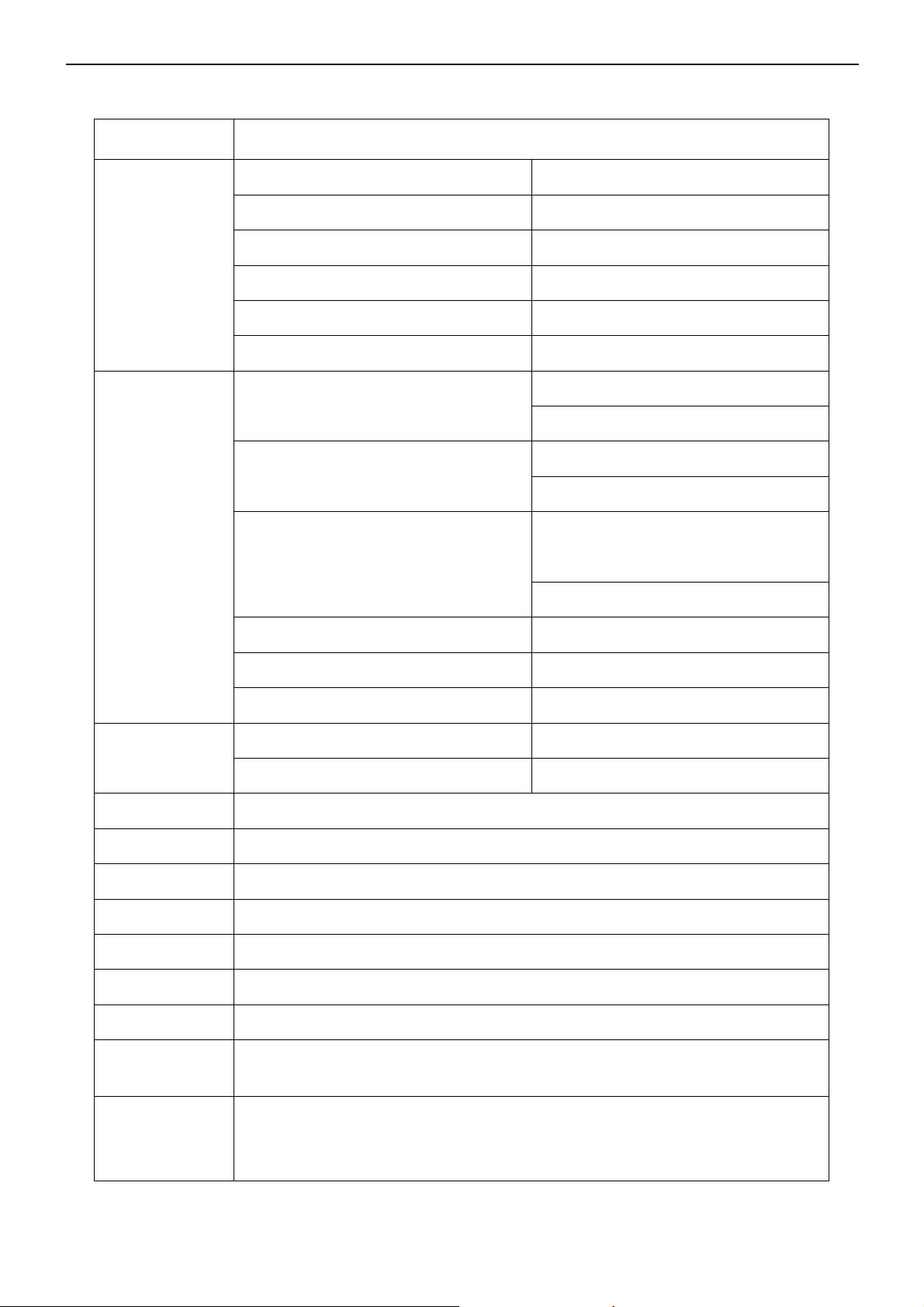
1. Monitor Specifications
Items Descriptions
Driving system TFT Color LCD
LCD Panel
Input
Type
Size 43.2cm 17"
Pixel pitch 0.264mm( H )x 0.264mm( V )
Viewable angle 160˚ (H) 160˚ (V) (CR≥10)
Response time (type) 5 ms for CPT
Video
Connector
Video Signal
Sync. Type H/V TTL
75 OHM, Positive and TMDS
CLAA170EA07
R,G,B Analog Interface
Digital Interface
15-pin D-Sub
DVI 24pin
Analog:0.7Vp-p(standard),
Digital signal
H-Frequency 30kHz – 83kHz
V-Frequency 55-75Hz
Power
Consumption
Contrast Ratio 700:1
Dot Clock 135 MHz
White Luminance 300cd/m2
Max. Resolution 1280 x1024
Display Color 16.7M colors
Plug & Play VESA DDC2BTM
Power Source 100~240VAC,47~63Hz
Maximum Screen
Size
Environmental
Considerations
Horizontal : 337.96 mm
Vertical: 270.34 mm
Operating Temp: 5°C to 35°C
Storage Temp: -20°C to 60°C
Operating Humidity: 10% to 85%
ON Mode ≤37W
OFF Mode ≤1W
4
Page 5
17” LCD Color Monitor AOC 177Pk
(
)
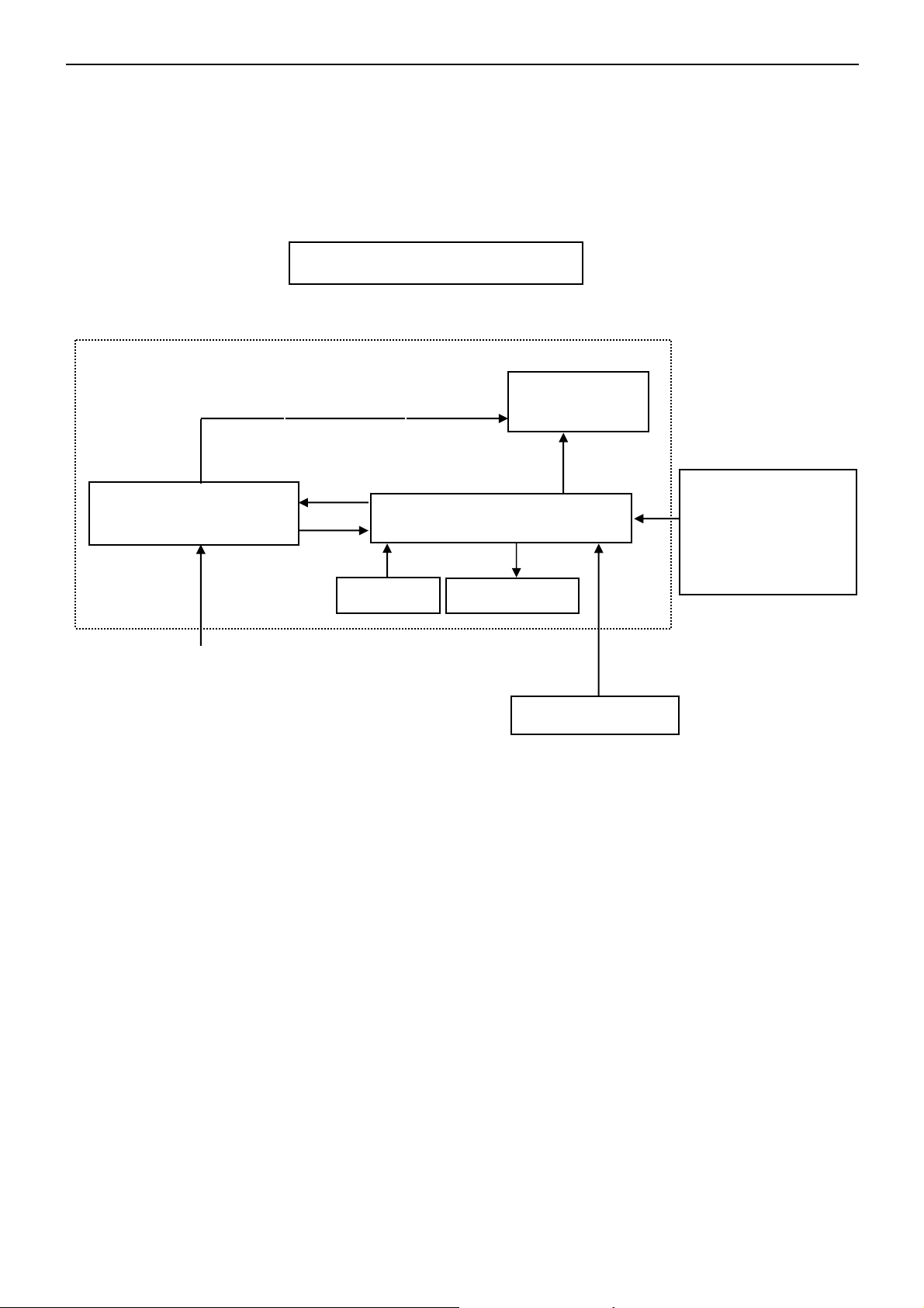
2. LCD Monitor Description
The LCD MONITOR will contain a main board, an audio board, a power board and a key board which house the flat
panel control logic, brightness control logic and DDC.
The power board will provide AC to DC Inverter voltage to drive the backlight of panel and the main board chips
each voltage.
Monitor Block Diagram
Power Board
Include: adapter, inverter
AC-IN
100V-240V
CCFL Drive.
Key Board
Flat Panel and
CCFL backlight
Main Board
Audio Board
RS232 Connector
For white balance
adjustment in factory
mode
Video signal, DDC
HOST Computer
5
Page 6
17” LCD Color Monitor AOC 177Pk
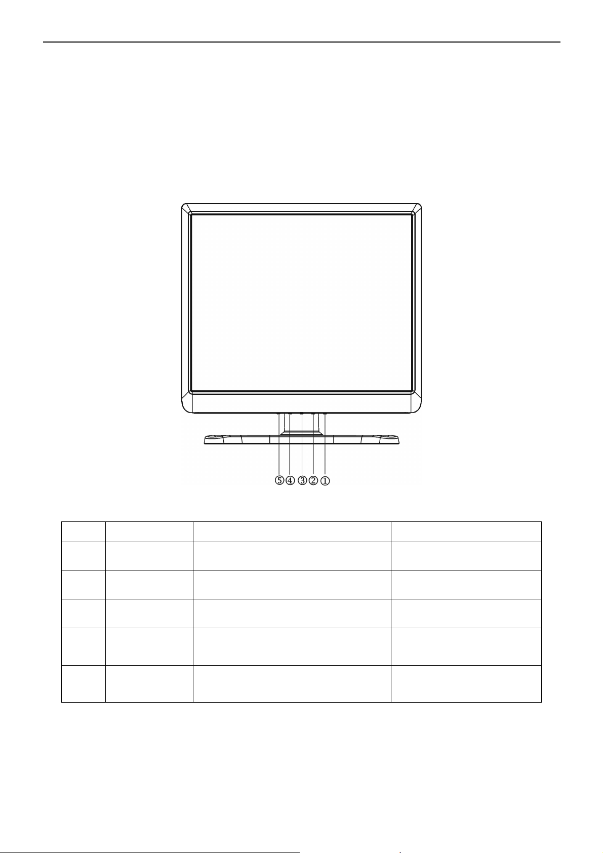
3. Operating Instructions
3.1 General Instructions
Press the power button to turn the monitor on or off. The control buttons are located at front panel of the monitor.
By changing these settings, the picture can be adjusted to your personal preferences.
The power cord should be connected.
-
Connect the video cable from the monitor to the video card.
-
Press the power button to turn on the monitor, the power indicator will light up.
-
3.2 Control Buttons
Item
1 > / Audio
2 < / audio
3 Power Power On / Off
4 Menu/Enter Select Function or select Sub menu Activate OSD main menu
5 Auto/Exit Exit OSD or back to previous menu Auto configuration
Name
1.Move the cursor up
2.Increase the value of the selected item
1.Move the cursor down
2.Decrease the value of the selected item
Within OSD
Activate the audio menu
Activate the audio menu
Power On / Off
Without OSD
6
Page 7
17” LCD Color Monitor AOC 177Pk
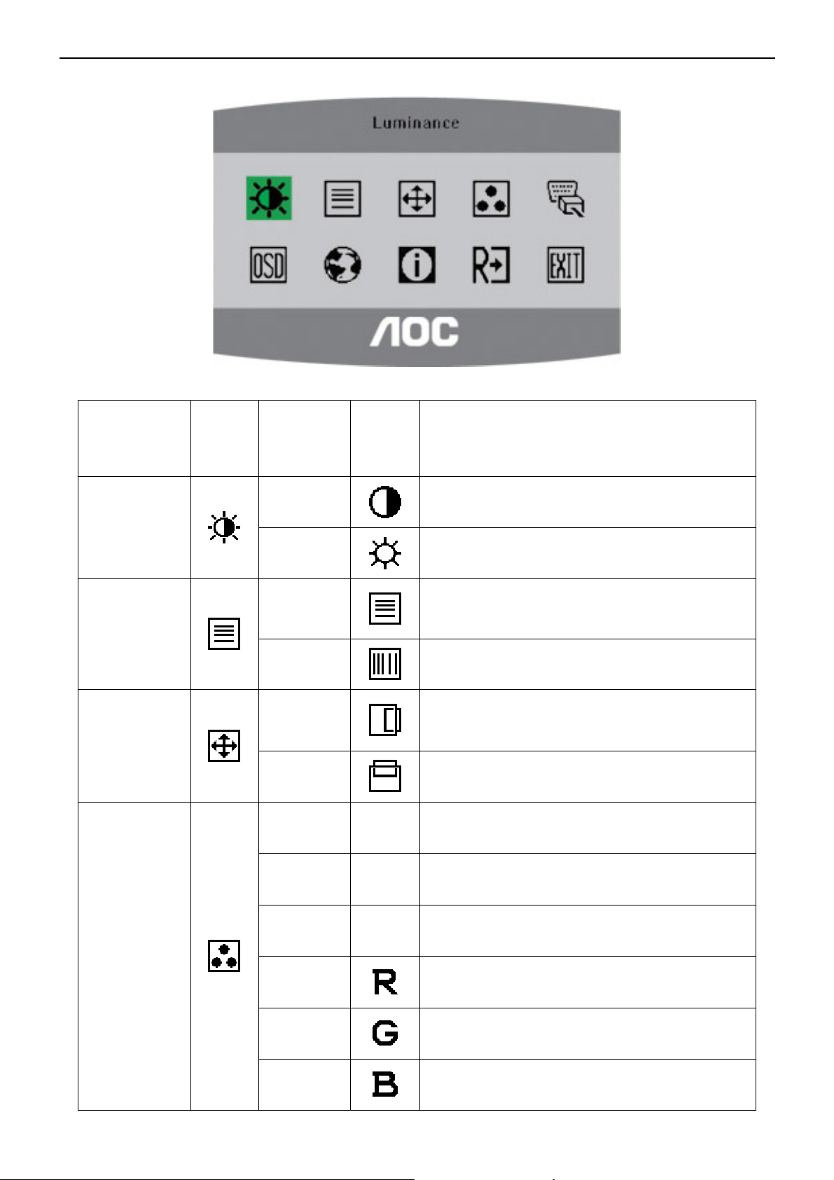
3.3 Adjusting the Picture
OSD functions
Main Menu Item
Luminance
Image Setup
Image Position
Main
Menu
Icon
Sub Menu
Brightness
H. Position
V. Position
Item
Contrast
Focus
Clock
Sub
Menu
Icon
Description
Contrast from Digital-register.
Backlight Adjustment
Adjust Picture Phase to reduce Horizontal-Line noise
Adjust picture Clock to reduce Vertical-Line noise.
Adjust the horizontal position of the picture.
Adjust the vertical position of the picture.
Color Temp.
Warm N/A Recall warm Color Temperature from EEPROM.
Cool N/A Recall cool Color Temperature from EEPROM.
sRGB N/A Recall sRGB Color Temperature from EEPROM.
User / Red
User / Green
User / Blue
7
Red Gain from Digital-register.
Green Gain Digital-register.
Blue Gain from Digital-register.
Page 8
17” LCD Color Monitor AOC 177Pk
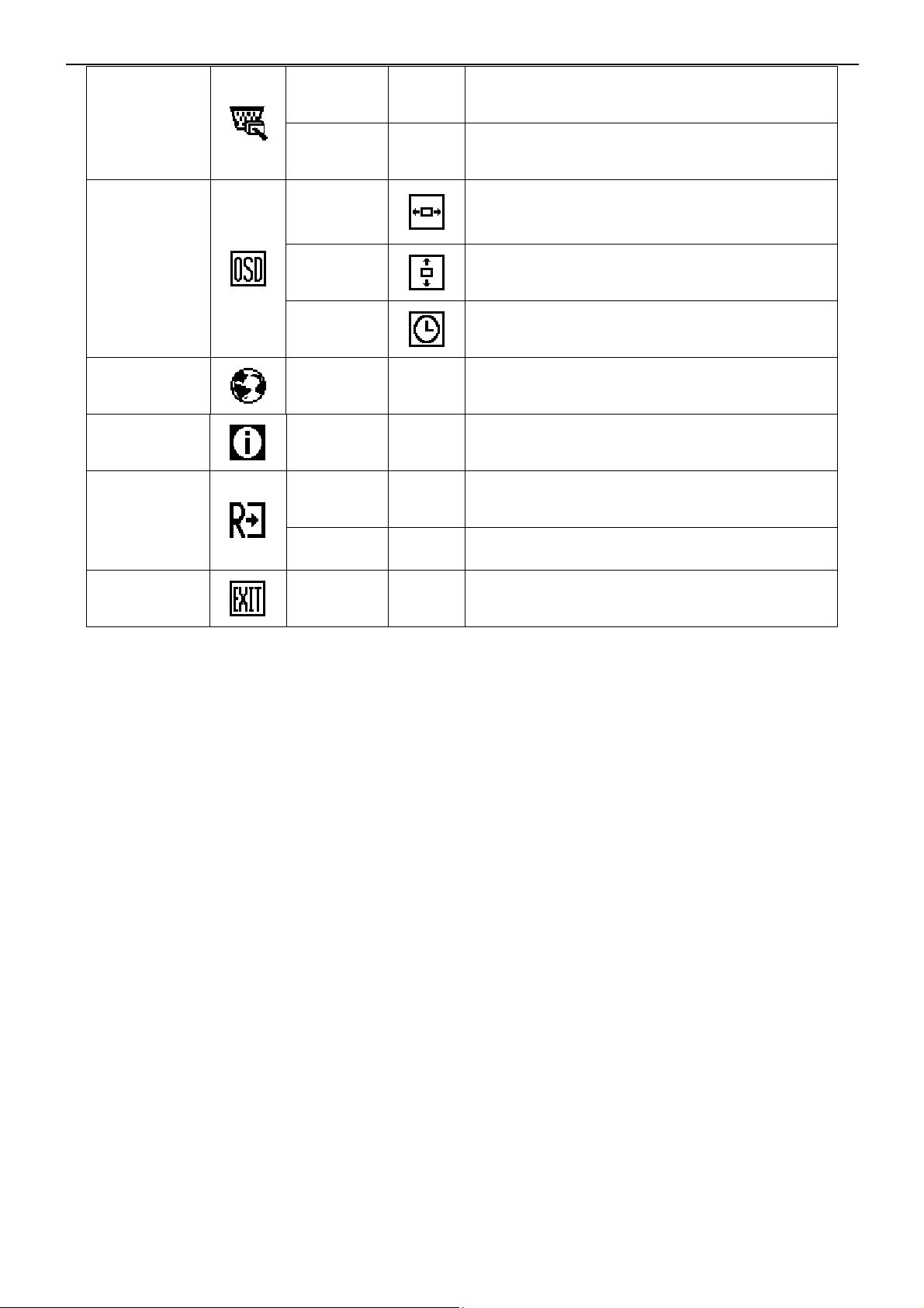
Analog N/A Select input signal from analog source (D-Sub)
Input Select
OSD Setup
Language
Information
Reset
Digital N/A Select input signal from digital source (DVI)
H. Position
V. Position
OSD Timeout
Language N/A Select the language you like.
Information N/A
Yes N /A
No N/A Do not execute reset, return to main menu.
Adjust the horizontal position of the OSD.
Adjust the vertical position of the OSD.
Adjust the OSD timeout.
Show the resolution, H/V frequency and input port of
current input timing.
Clear each old status of Auto-configuration and set
the color temperature to Cool.
Exit
N/A N/A Exit OSD
8
Page 9
17” LCD Color Monitor AOC 177Pk
4. Input/Output Specification
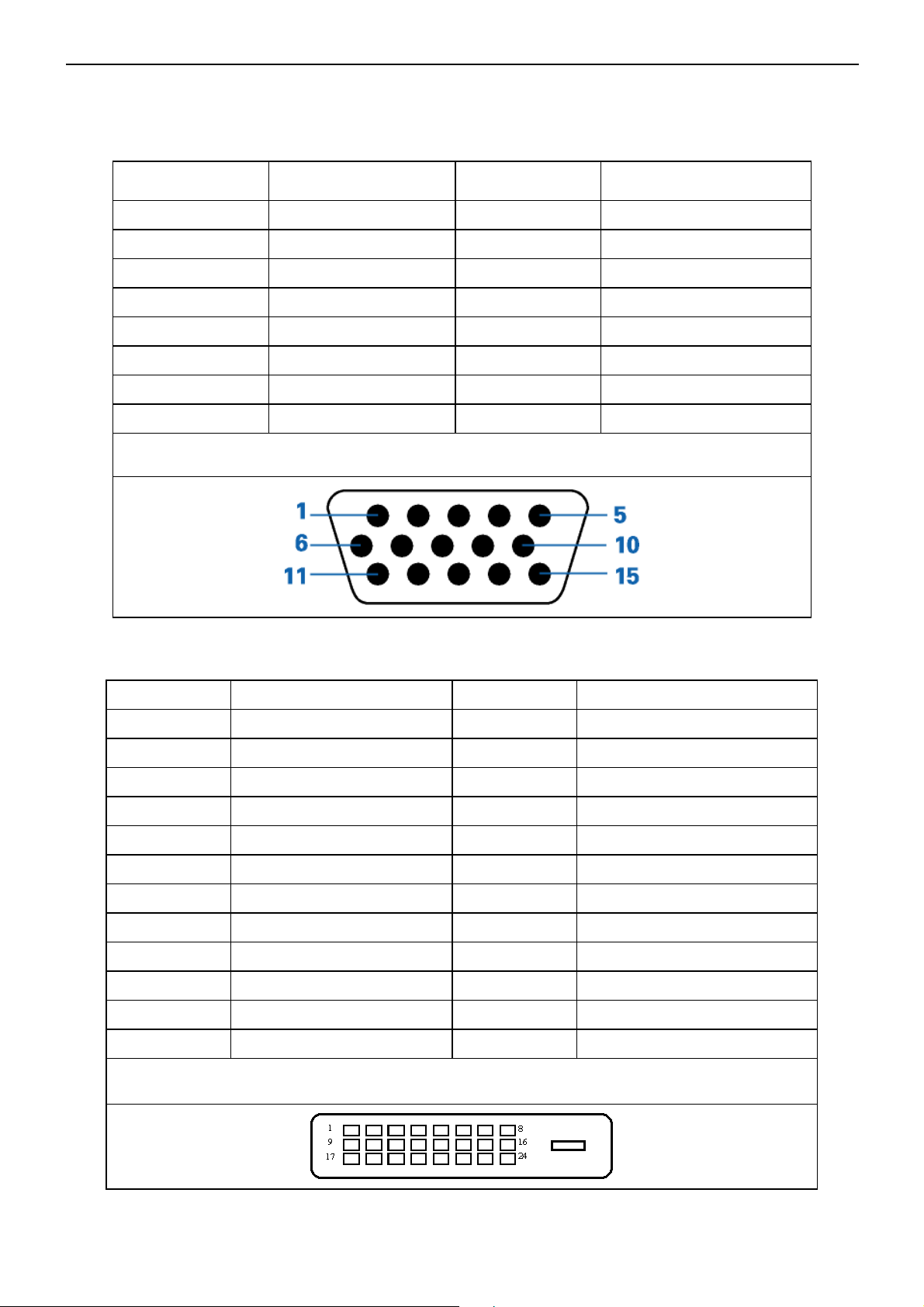
4.1 Input Signal Connector
1. D-SUB connector
Pin No. Description Pin No. Description
1.
2.
3.
4.
5.
6.
7.
8.
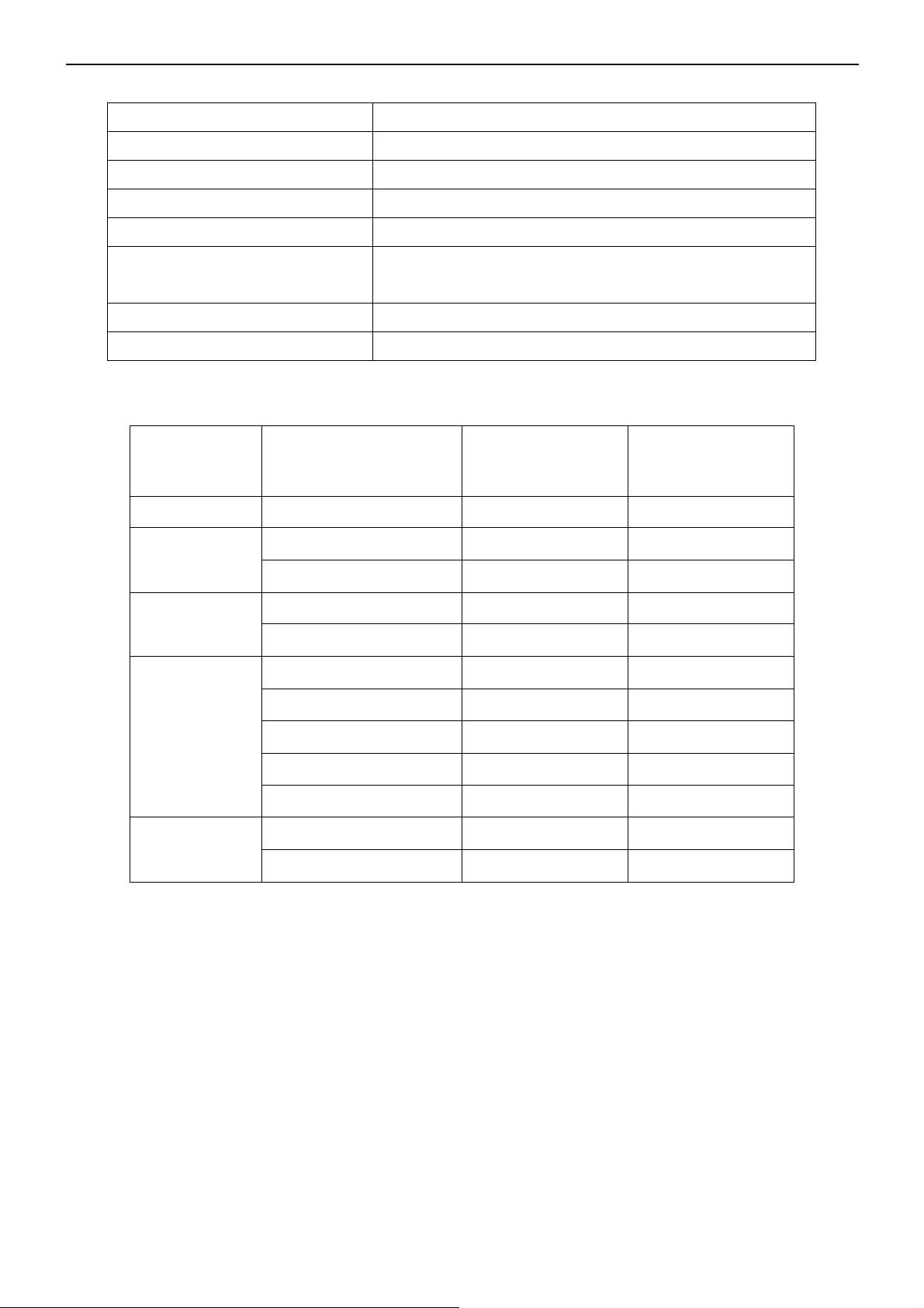
2. DVI-D connector
Red
Green
Blue
Ground
DDC-Return
R-Ground
G-Ground
B-Ground
VGA connector layout
9.
10.
11.
12.
13.
14.
15.
+ 5V
Detect Cable
Ground
DDC-Serial Data
H-Sync
V-Sync
DDC-Serial Clock
Pin No. Description Pin No. Description
1.
2.
3. TMDS data 2/4 Shield 15. GND (for +5V)
4.
5.
6. DDC Clock 18.
7. DDC Data 19. TMDS data 0/5 Shield
8. NC 20.
9.
10.
11. TMDS data 1/3 Shield 23. TMDS Clock +
12.
TMDS data 2-
TMDS data 2+
TMDS data 4-
TMDS data 4+
TMDS data 1-
TMDS data 1+
TMDS data 3-
24 - Pin Color Display Signal Cable
13.
14.
16. Hot Plug Detect
17.
21. TMDS data 5+
22. TMDS Clock Shield
24.
TMDS data 3+
+5V Power
TMDS data 0-
TMDS data 0+
TMDS data 5-
TMDS Clock -
9
Page 10
17” LCD Color Monitor AOC 177Pk
4.2 Power Supply Requirement
A/C Line voltage range : 100 V ~ 240 V
A/C Line frequency range
Current : TBD
Peak surge current : < 55A peak at 240 VAC and cold starting
Leakage current : < 3.5mA
Power line surge
DC output Voltage
Current (max) : 3.5 Amp (12V)
4.3. Factory Preset Display Modes
Standard
Dos-mode 720 × 400 31.47kHz 70.0Hz
VGA
Resolution
640 × 480 31.47kHz 60.0Hz
640 × 480 37.50kHz 75.0Hz
: 50 ± 3Hz, 60 ± 3Hz
: No advance effects (no loss of information or defect) with a
maximum of 1 half-wave missing per second
: 12VDC ± 5%
Horizontal
Frequency
Vertical
Frequency
SVGA
XGA
SXGA
800 × 600 37.879kHz 60.0Hz
800 × 600 46.875kHz 75.0Hz
1024 × 768 48.363kHz 60.0Hz
1024 × 768 56.476kHz 70.0Hz
1024 × 768 60.02kHz 75.0Hz
1024 × 768 48.780 kHz 60.0Hz
1024 × 768 60.241 kHz 75.0Hz
1280 × 1024 64.00 kHz 60.0Hz
1280 × 1024 80.00 kHz 75.0Hz
10
Page 11
17” LCD Color Monitor AOC 177Pk
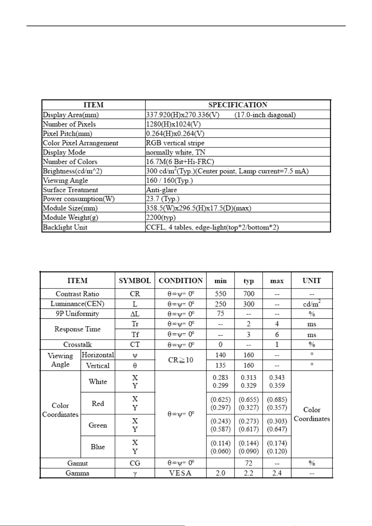
4.4 Panel Specification
CLAA170EA07P2 is 17.0” color TFT-LCD (Thin Film Transistor Liquid Crystal Display) module composed of LCD
panel, driver ICs, control circuit and backlight. By applying 8 bit digital data, 1280×1024, 16.7M-color images are
displayed on the 17.0” diagonal screen. Input power voltage is 5.0V for LCD driving. Inverter for backlight is not
included in this module. General specification are summarized in the following table:
4.4.1 Display Characteristics
4.4.2 Optical Characteristics
Ta= 25 ℃,VCC=5.0V
11
Page 12
17” LCD Color Monitor AOC 177Pk
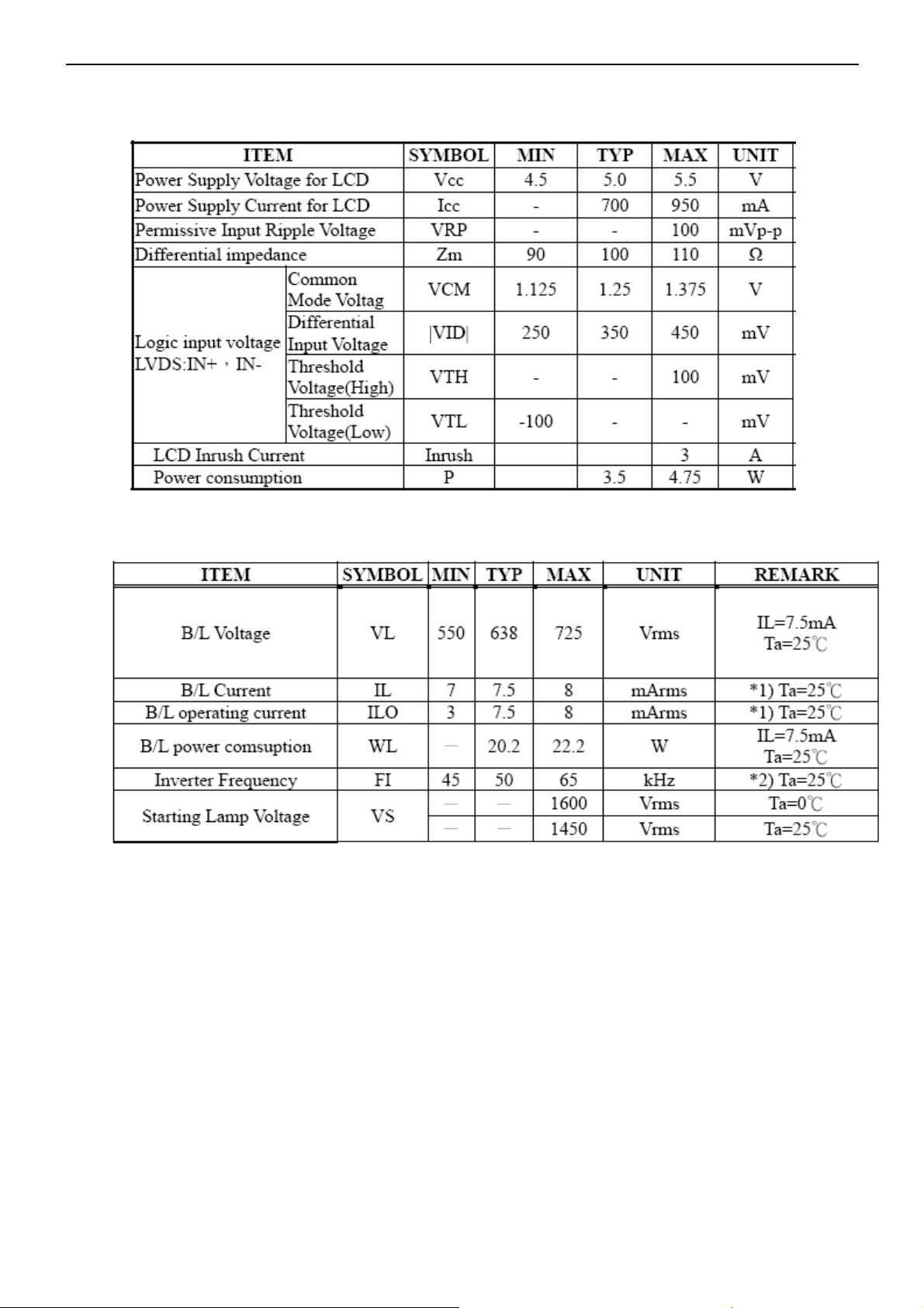
4.4.3 Electrical Characteristics
1. TFT LCD Module
2. Backlight Unit
12
Page 13
17” LCD Color Monitor AOC 177Pk
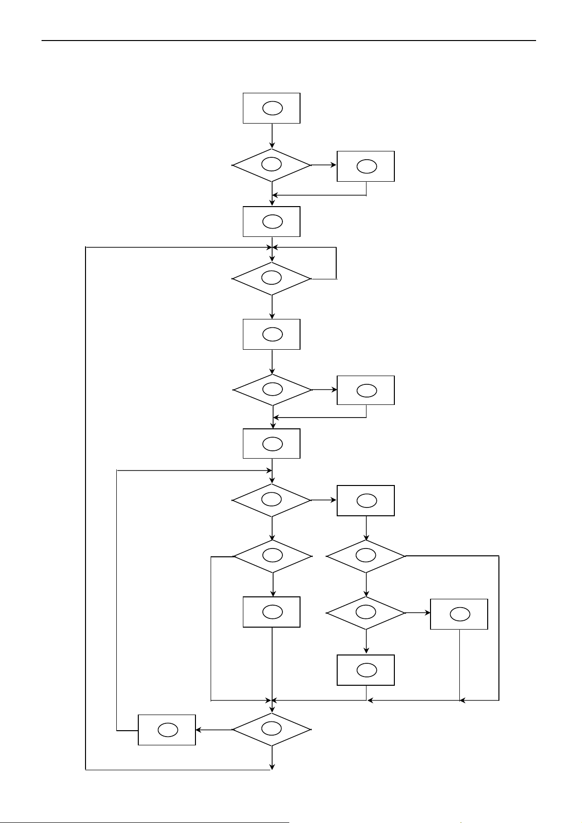
5. Block Diagram
5.1 Software Flow Chat
1
2
N
4
5
Y
6
7
Y
Y
3
N
N
8
18
9
1
Y
N
N
12
Y
14
19
N
11
N
13
Y
N
15
Y
17
16
Y
13
Page 14
17” LCD Color Monitor AOC 177Pk
1) MCU initialize.
2) Is the EPROM blank?
3) Program the EPROM by default values.
4) Get the PWM value of brightness from EPROM.
5) Is the power key pressed?
6) Clear all global flags.
7) Are the AUTO and SELECT keys pressed?
8) Enter factory mode.
9) Save the power key status into EPROM.
Turn on the LED and set it to green color.
Scalar initializes.
10) In standby mode?
11) Update the lifetime of back light.
12) Check the analog port, are there any signals coming?
13) Does the scalar send out an interrupt request?
14) Wake up the scalar.
15) Are there any signals coming from analog port?
16) Display "No connection Check Signal Cable" message. And go into standby mode after the message
disappear.
17) Program the scalar to be able to show the coming mode.
18) Process the OSD display.
19) Read the keyboard. Is the power key pressed?
14
Page 15
17” LCD Color Monitor AOC 177Pk
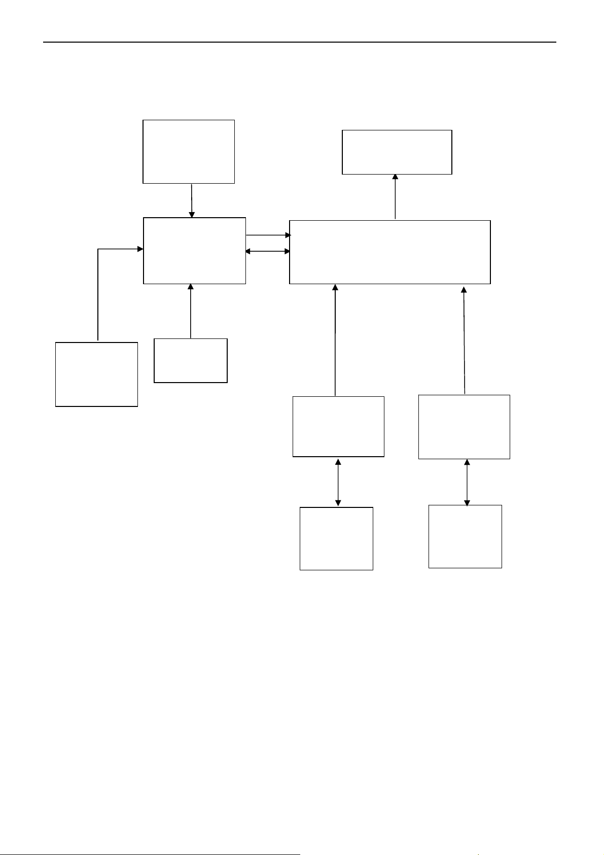
5.2 Electrical Block Diagram
5.2.1 Main Board
Flash Memory
AT24C16AN
(U302)
EPR_SDA
EPR_SCL
Crystal
24MHZ
(X301)
MCU
RTD2120L
(U402)
Key Board
Control
CLKOUT
(CN504)
Scalar IC RTD2525L
(Included ADC, OSD)
(U401)
H sync
V sync
RGB
D-Sub
Connector
(CN702)
DDC1_SDA,
DDC1_SCL
PANEL
D-DVI
Connector
(CN701)
DDC2_SDA,
DDC2_SCL
EEPROM
M24C02
(U702)
EEPROM
M24C02
(U701)
15
Page 16
17” LCD Color Monitor AOC 177Pk
t
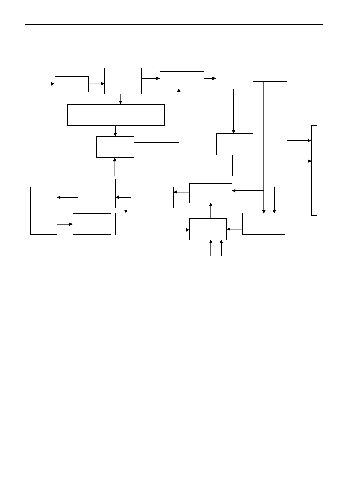
5.2.2 Inverter/Power Board
AC input
EMI filter
Bridge
Rectifier
and Filter
Transformer
Rectifier
diodes
Start Circuit: R911
CN902
PWM
Control IC
Feedback
Circuit
12V
5V
Lamp
Output
Circuit
Feedback
Circui
Transformer
Over
Voltage
ON/OFF
MOSFET
PWM
Control IC
ON/OFF
Control
DIM
DIM
16
Page 17
17” LCD Color Monitor AOC 177Pk
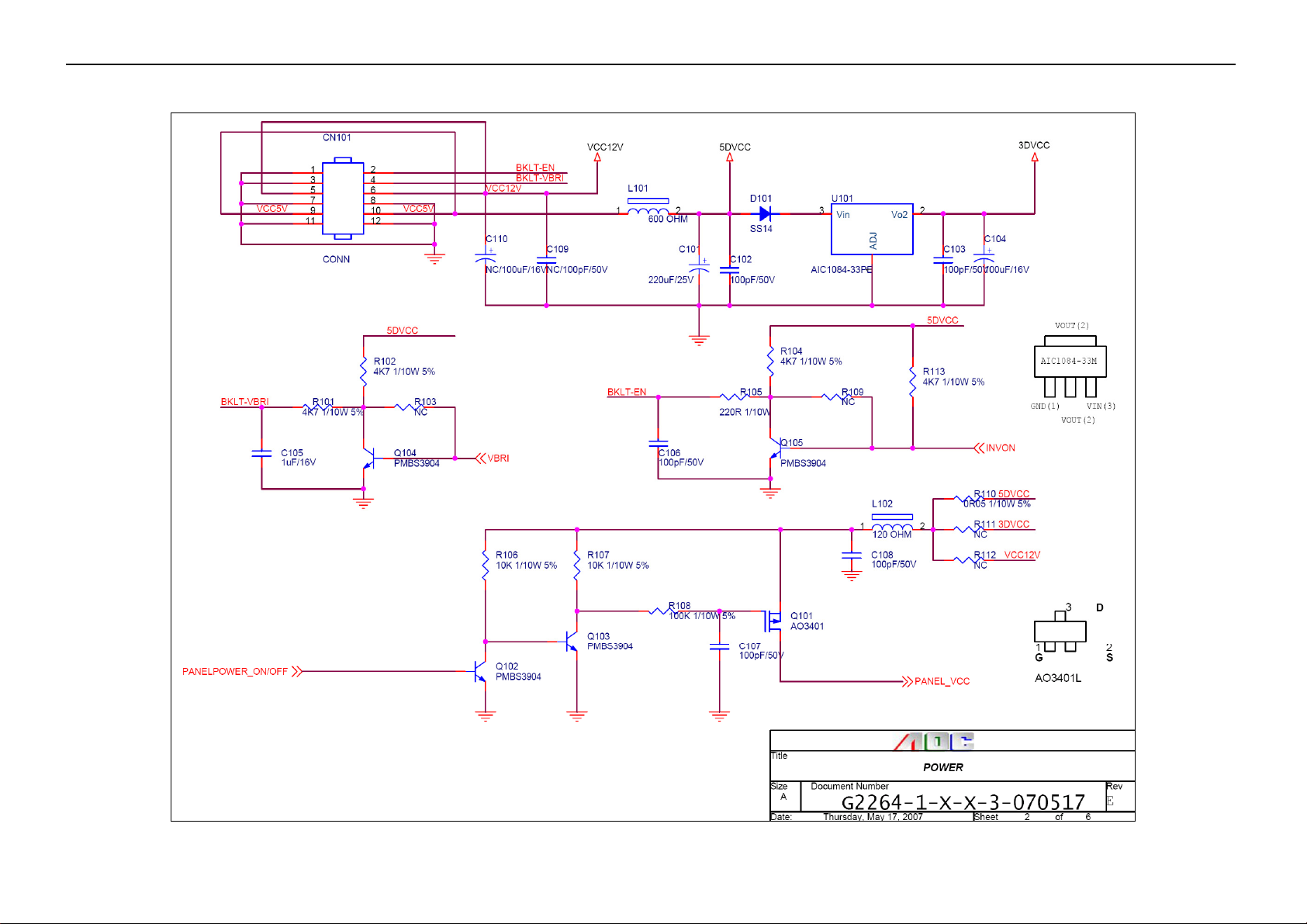
6. Schematic
6.1 Main Board
17
Page 18

17” LCD Color Monitor AOC 177Pk
18
Page 19

17” LCD Color Monitor AOC 177Pk
19
Page 20

17" LCD Color Monitor AOC 177Pk
20
Page 21

17" LCD Color Monitor AOC 177Pk
21
Page 22

17" LCD Color Monitor AOC 177Pk
6.2 Audio Board
715G1841-2
OUT_L
CN204
NC-CONN
CN201
PHONEJAC K
12V
CN202
13
11
1
2
3
GND
1
2
3
4
5
GND
R201
18K 1/16W
R203 18K 1/16W
C211
0.01uF
R210
20K 1/16W
R211
20K 1/16W
VOLUME
C214
NC
220K
C212
0.01uF
R212
+12V
+
10uF/50V
C204 0.47uF/ 25V
C206
0.47uF /25V
C209
+
10uF/50V
GND
C210
9
7
5
3
1
STANDBY
C213
0.1uF
4
9
6
11
12
CONN
14
12
10
8
6
4
2
INL
INR
VOLUME
STBY
MUTE
8
GND
123
NC
GND
MUTE
16
GND
13
+12V
15
VS
VS
OUTL
OUTR
SVR
VAROUT_R
VAROUT_L
GND
GND
GND
GND
181920
+
C201
470uF/16V
U201
E-TDA7496L
17
14
10
7
5
C208
470uF/ 16V
+
C202
470uF/16V
+
R202
200K 1/16W
GND
R207
C203
0.1uF
C205
+
470uF/ 16V
+
470uF/ 16V
C207
R208
1K 1/16W
1K 1/16W
OUT_R
GND
GND
GND
Tit le
GND
Audio
Size Document Number Rev
Dat e: Sheet
22
<Do c> 1
A
11Wednesday , January 25, 2006
of
Page 23

17" LCD Color Monitor AOC 177Pk
6.3 Power Board
715G1823-2
C901
1000pF
330KΩ 1/4W
R900
2
1
+
-
4
L902
142
7.0mH
L901
124
L
C909
0.47uF
330KΩ 1/4W
R901
330KΩ 1/4W
3
CN901
SOCKET
R951
47Ω 1/4W
R922
470Ω 1/4W
12
9
7
11
10
8
12
R952
47Ω 1/4W
47Ω 1/4W
R925
1KΩ 1/8W
C928
0.1uF
R928
1KΩ 1/8W
BD1
2KBP08M
IC921
4
5
6
4
6
1
3
0.0033uF/ 250V
43
T901
POWER X'FMR
C905
C900
0.0022UF
3
+
C910
100uF/450V
3
C902
NR901
NTCR
F901
FUSE
1000pF
100KΩ 1/8W
3
R902
12
R911
R911
10KΩ 1/4W
HV
NC
RT
COMPCSGNDOUT
123
1500pF/1KV
0.1uF
C912
678
U1
LD7575PS
VCC
4 5
C913
220pF
C914
470pF/25V
R913
1KΩ 1/8W
C916
0.1uF
LL4148WP
D910
10Ω 1/4W
R912
22uF/50V
C911
+
BA159GPT
D901
UF4003PT
R915
10KΩ 1/8W
C910
D900
R909
100KΩ 2W
R910
7.5Ω 1/4W
Q900
FQPF8N 60C
R916
0.43Ω 2W
PC123X2YFZ OF
IC902
KIA431A-AT/P
47Ω 1/4W
R954
R955
0.001uF/ 500V
D920
3
SBT150-10LST
2
1
31DQ06FC
D922
C921 0.001uF/500V
C920
IND CHOKE 3.5uH+-10% DADONG
+
+
C922
C924
680uF/25V
680uF/25V
IND CHOKE 3.5uH+-10% DADONG
C926
+
1000uF/16V
ZD922
ZD921
RLZ5.1B
RLZ13B
1 2
1 2
D916
D915
1N4148W
1N4148W
R927
100Ω 1/8W
+
C923
680uF/25V
L922
C932
+
470uF/16V
L921
R923
10KΩ 1/8W
3.6KΩ 1/ 8W
C929
0.1uF
100Ω 1/8W
R930
+
+
C925
470uF/25V
ZD920
PTZ9.1B
C927
470uF/16V
R924
1 2
R929
2.4KΩ 1/8W
R956
33KΩ 1/8W
ON/O FF
R931
10KΩ 1/4W
C931
0.1uF
DIM
C930
0.1uF
+12V
+5V
CN902CONNECTOR
10
9
8
7
6
5
4
3
2
1
Tit le
<Title>
Size Document N umber Rev
<Doc >
B
Date: Sheet
PWP C742HE1P
PWP C742HE1P
715G1823 2
of
11Tuesday , September 19, 2006
23
Page 24

17" LCD Color Monitor AOC 177Pk
CN801
2
1
CONN
CN802
2
1
CONN
+12V
ON/OFF
PT801
6
7
POWER X'F MR
R836
1KΩ 1/8W
R825
560Ω 1/8W
C835
0Ω 1/4W
C836
0Ω 1/4W
3
4
10Ω 1/8W
R842
R818
15Ω 1/4W
C812
0.0015uF/50V
876
DDD
SGS
123
5
Q805
D
AM9945N-T1-PF
G
4
IC801
1
DRV1
PGND
2
VDDA
DRV2
3
TIMER
GNDA
4
DIM
CT
5
ISEN
SSTCMP
6
VSEN
LCT
7
OVPT
ENA
8 9
NC1 NC2
OZ9938GN
R819
15Ω 1/4W
C813
0.0015uF/50V
10Ω 1/8W
16
R837
15
14
13
12
11
10
BAV70
100KΩ 1/8W
R815
C807
0.01uF
1 8
C830
47pF
2
D801
1MΩ 1/8W
R816
39KΩ 1/8W
C808
0.0068uF
3
C809
0.047uF
Q801
PMBS3904
2.2uF/16V
R804
10KΩ 1/4W
Q802
PMBS3904
R812
10KΩ 1/8W
C804
1 2
1MΩ 1/8W
R809
ZD801
RLZ5.6B
R802
300KΩ 1/4W
R803
10KΩ 1/8W
DIM
R808
470K 1/4W
C803
0.01uF
C805
0.001uF
R805
470Ω 1/4W
100KΩ 1/8W
R810
C811
470uF/25V
Q803
PMBS3904
VCC
R807
22Ω 1/4W
R814
56KΩ 1/8W
+
1uF/25V
C806
1
R817
100KΩ 1/8W
R821
R820
15KΩ 1/8W
C810
470pF/50V
C816
12pF/3KV
C831
270pF
C817
3pF/3KV
C818
270pF
0.022uF/25V
C819
R822
3MΩ 1/2W
R827
3.6KΩ 1/8W
390Ω 1/8W
R826
R841
360Ω 1/8W
BAV99
2
3
1
D803
R811
150KΩ 1/8W
Titl e
<Title>
Size Document Number Rev
<Doc >
A3
Date: Sheet
PWP C742HE1P
715G1823 2
of
1Tuesday, September 19, 2006
R813
1MΩ 1/8W
C820
470uF/25V
PT802
6
7
POWER X'FMR
R835
560Ω 1/8W
C837
0Ω 1/4W
C838
0Ω 1/4W
3
4
1 8
C832
47pF
D803
BAV70
2
DDD
SGS
R829
15Ω 1/4W
C823
0.0015uF/50V
5
Q806
D
AM9945N-T1-PF
G
4
R828
+
15Ω 1/4W
C822
0.0015uF/50V
876
123
100KΩ 1/8W
R831
R830
15KΩ 1/8W
1
3
C825
12pF/3KV
C826
3pF/3KV
C827
270pF
C833
100pF
R832
3MΩ 1/2W
R834
3.6KΩ 1/8W
2
1
R843
1KΩ 1/8W
BAV99
3
D804
CN803
2
1
CONN
CN804
2
1
CONN
24
Page 25

17" LCD Color Monitor AOC 177Pk
7. PCB Layout
7.1 Main Board
25
Page 26

17" LCD Color Monitor AOC 177Pk
26
Page 27

17" LCD Color Monitor AOC 177Pk
7.2 Power Board
27
Page 28

17" LCD Color Monitor AOC 177Pk
28
Page 29

17" LCD Color Monitor AOC 177Pk
7.2 Audio Board
715G1841-2
7.4 Key Board
715G1819-1-2
29
Page 30

17" LCD Color Monitor AOC 177Pk
8. Maintainability
8.1 Equipments and Tools Requirement
1. Voltmeter.
2. Oscilloscope.
3. Pattern Generator.
4. DDC Tool with an IBM Compatible Computer.
5. Alignment Tool.
6. LCD Color Analyzer.
7. Service Manual.
8. User Manual.
30
Page 31

17" LCD Color Monitor AOC 177Pk
8.2 Trouble Shooting
8.2.1 Main Board
No power
No power
Press power key and look
if the picture is normal
NG
Please reinsert and make sure
the AC of 100-240 is normal
OK
Measure
U101 PIN2=3V
NG
Reinsert or check the
Adapter/Inverter
section
OK
NG
Check U101
X301 oscillate waveforms
are normal
OK
NG
Replace X301
Replace U402
OK
NG
Replace U402
Replace U401
31
Page 32

17" LCD Color Monitor AOC 177Pk
No picture (LED orange)
No picture
The button if
under control
OK
Measure U101 PIN2=3V
OK
NG
Check U101
X301 oscillate
waveform is normal
OK
NG
Replace X301
Check HS/VS from
CN702 is normal
NG
OK
Check Correspondent
component
Replace U402
NG
Replace U402
OK
Replace U401
32
Page 33

17" LCD Color Monitor AOC 177Pk
White screen
White screen
Measure Q102 base
is high level?
NG
X301 oscillate
waveform is normal
OK
OK
NG
Replace X301
Check Q101, Q102, Q103 are
broken or CN504 solder?
NG
OK
Check Correspondent
component.
Check reset circuit of
U402 is normal
NG
OK
Replace U402
Check Correspondent
component.
NG
Replace PANEL
OK
Replace U401
Replace U401
33
Page 34

17" LCD Color Monitor AOC 177Pk
8.2.2 Power/Inverter Board
(1) No power
Check CN902 pin3/4 = 12V
NG
Check AC line volt 110V or 220V
OK
NG
Check AC input
Check the voltage of C910 (+)
OK
NG
Check bridge rectified circuit and F901 circuit
Check start voltage for the pin8 of IC901
OK
NG
Check R911, C910 and Change IC901
Check the auxiliary voltage is bigger than
10V and smaller than 20V
OK
NG
1) Check IC901
2) Check IC901 over current protect circuit
Check IC901 pin5 PWM wave
OK
NG
Check IC901
Check Q900, D916, D915, ZD921, ZD922, IC902 and T901
34
Page 35

17" LCD Color Monitor AOC 177Pk
2.) W / LED, No Backlight
Check CN902 pin3,4 = 12V
OK
NG
Check adapter or MB
Check ON/OFF signal
OK
NG
Check Interface board
Check IC801 pin2=5V
OK
NG
Change Q802 or Q803
Check IC801 PIN1/15 have the output of square wave at short
OK
Check Q805, Q806 PIN5, 8= 12V
OK
Check the output of PT801, PT802
OK
NG
NG
NG
Check IC801 PIN5/6
Check Q805, Q806
Check PT801, PT802
Check connecter & lamp
35
Page 36

17" LCD Color Monitor AOC 177Pk
8.2.3 Keypad Board
OSD is unstable or not working
Is Key Pad Board connecting normally?
N
Connect Key Pad Board
Y
Is Button Switch normally?
N
Replace Button Switch
Y
Is Key Pad Board normally?
N
Replace Key Pad Board
Y
Check Main Board
36
Page 37

17" LCD Color Monitor AOC 177Pk
9. White-Balance, Luminance Adjustment
Approximately 30 minutes should be allowed for warm up before proceeding White-Balance adjustment.
1. How to do the Chroma-7120 MEM. Channel setting
A. Reference to chroma 7120 user guide
B. Use “ SC” key and “ NEXT” key to modify
yY value and use “ID” key to modify the
X
TEXT description Following is the procedure to do white-balance adjust
2. Setting the color temp. you want
A. MEM.CHANNEL 3 (Warm color):
6500 color temp. parameter is x = 313±20, y = 329 ±20, Y =180 cd/m2
B. MEM.CHANNEL 4 (Cool color):
7800 color temp. parameter is x = 296 ±20, y = 311 ±20, Y = 180 cd/m
C. MEM.CHANNEL 9 (sRGB color):
sRGB color temp. parameter is x = 313±20, y = 329 ±20, Y =180 cd/m
2 ,
2
3. Into factory mode of AOC 177Pk
Turn on power, press the MENU button, pull out the power cord, and then plug the power cord. Then the factory
OSD will be at the left top of the panel.
4. Bias adjustment:
Set the Contrast
to 50; Adjust the Brightness to 80.
5. Gain adjustment:
Move cursor to “-F-” and press MENU key
A. Adjust Warm color-temperature
1. Switch the chroma-7120 to RGB-Mode (with press “MODE” button)
2. Switch the MEM.channel to Channel 3 (with up or down arrow on chroma 7120)
3. The LCD-indicator on chroma 7120 will show x = 313 ±20, y = 329 ±20, Y = 180 cd/m
2
4. Adjust the RED of color3 on factory window until chroma 7120 indicator reached the value R=100
5. Adjust the GREEN of color3 on factory window until chroma 7120 indicator reachedthe value G=100
6. Adjust the BLUE of color3 on factory window until chroma 7120 indicator reached the value B=100
7. Repeat above procedure (item 4,5,6) until chroma 7120 RGB value meet the tolerance =100±2
37
Page 38

17" LCD Color Monitor AOC 177Pk
B. Adjust Cool color-temperature
1. Switch the Chroma-7120 to RGB-Mode (with press “MODE” button)
2. Switch the MEM. Channel to Channel 4 (with up or down arrow on chroma 7120)
2
3. The LCD-indicator on chroma 7120 will show x = 296 ±20, y = 311 ±20, Y =180 cd/m
4. Adjust the RED of color1 on factory window until chroma 7120 indicator reached the value R=100
5. Adjust the GREEN of color1 on factory window until chroma 7120 indicator reached the value G=100
6. Adjust the BLUE of color1 on factory window until chroma 7120 indicator reached the value B=100
7. Repeat above procedure (item 4,5,6) until chroma 7120 RGB value meet the tolerance =100±2
C. Adjust sRGB color-temperature
1. Switch the chroma-7120 to RGB-Mode (with press “MODE” button)
2. Switch the MEM.channel to Channel 9 (with up or down arrow on chroma 7120)
3. The LCD-indicator on chroma 7120 will show x = 313 ±20, y = 329 ±20, Y = 180 cd/m
4. Adjust the RED of color3 on factory window until chroma 7120 indicator reached the value R=100
5. Adjust the GREEN of color3 on factory window until chroma 7120 indicator reachedthe value G=100
6. Adjust the BLUE of color3 on factory window until chroma 7120 indicator reached the value B=100
7. Repeat above procedure (item 4,5,6) until chroma 7120 RGB value meet the tolerance =100±2
D. Turn the Power-button off to quit from factory mode.
2
38
Page 39

17" LCD Color Monitor AOC 177Pk
10. Monitor Exploded View
39
Page 40

17" LCD Color Monitor AOC 177Pk
40
Page 41

17" LCD Color Monitor AOC 177Pk
41
Page 42

17" LCD Color Monitor AOC 177Pk
11. BOM List
T76CRTDBF1ACA
Location Part No. Description
015G5786 1 VRSA BRACKET
019G6034 1 GP STOPPER PIN
040G 581 26704 SHIPPING LABEL
040G 581689 4A SERIAL LABEL FOR MONITOR
041G 68508 A CONTROL CARD
044G3231 5 EVA WASHER
044G6002834 2A GP PAPER BOARD
044G9003210 CORNER PAPER
044GH600 1 HANDLE 2
050G 600 4 HANDLE 1
052G 1186 SMALL TAPE
078G 322 1A KL SPK 8OHM 1.5W KUAIDA
078G 322 1A KR SPK 8OHM 1.5W KUAIDA
089G 725LAA DB D-SUB
089G1745GAA AC DVI CABLE
089G404A15N YH POWER CORD
095G8014 16655 KEY HARNESS
0M1G 130 5120 SCREW
0M1G 330 4120 SCREW 42A9930008
0M1G 330 6 47 CR3 SCREW 42-D005390
0M1G1140 6120 SCREW
0M1G1730 6120 SCREW
0M1G2640 10225 CR3 SCREW
0Q1G 330 8 47 CR3 SCREW
0Q1G 330 8120 SCREW 3X8MM 42A9930017/ 42-D002093
0Q1G1030 8120 SCREW
705GQ7K0P34022 BASE/STAND ASS'Y
001G6023 1 SCREW
037G 564 1 HINGE
0M1G 130 6225 CR3 SCREW
0M1G 130 8120 SCREW 42A9930022
0M1G 330 6 47 CR3 SCREW 42-D005390
0M1G2430 5 47 CR3 SCREW
0Q1G 130 6120 SCREW (T3X6)
0Q1G 330 5120 SCREW 42-D003574
Q12G6300 25 3 RUBBER
Q15G0105 1 LIFT BT
Q15G0106 1 LIFT BKT F
Q15G0107 1 BASE PLATE
Q15G8329 1 LOCK PIN
Q19G0002 3 SPRING
Q20G 042 1 LIFT BKT DIE CASTING
Q33G0076 GM 1L TAND COVER
42
Page 43

17" LCD Color Monitor AOC 177Pk
Q33G0099 GM 1L LOCK HOLDER
Q33G4998 GM 1L VESA COVER
Q33G4999 GM 1L HINGE COVER
Q33G5001 GM 1L LIFT COVER
Q33G5003 GM 1L STOP MYLON
Q33G5004 GM 1X LIFT BKT COVER
Q33G5005 GM 1X SPRING HOLDER
Q34G0099 GM 1B STAND
Q34G0115 GM 1B 20 BASE
750GLC70A7P13N PANEL CLAA170EA07P 000 FZ CPT
AUPC780KK6AP AUDIO BOARD
CN202 033G802414C H 2*7PIN DUAL ROW RIGHT ANGLE H
U201 056G 616 1 IC E-TDA7496L ST
C202 067G215V471 3N GP KY16VB470M-CC3 10*12.5
C201 067G215V471 3N GP KY16VB470M-CC3 10*12.5
C208 067G215V471 3N GP KY16VB470M-CC3 10*12.5
C207 067G215V471 3N GP KY16VB470M-CC3 10*12.5
C205 067G215V471 3N GP KY16VB470M-CC3 10*12.5
CN201 088G 30214K PHONE JACK 5PIN
U201 090G6093 1 HEAT SINK
R208 061G0603102 RST CHIP 1K 1/10W 5%
R207 061G0603102 RST CHIP 1K 1/10W 5%
R211 061G0603203 RST CHIPR 20 KOHM +-5% 1/10W
R210 061G0603203 RST CHIPR 20 KOHM +-5% 1/10W
R202 061G0603204 RST CHIPR 200 KOHM +-5% 1/10W
C211 065G0805102 32 CHIP 1000P 50VX7R 0805
C212 065G0805102 32 CHIP 1000P 50VX7R 0805
C213 065G0805104 32 CHIP 0.1U 50V X7R
C203 065G0805104 32 CHIP 0.1U 50V X7R
C206 065G0805474 22 CHIP 0.47UF 25V X7R 0805
C204 065G0805474 22 CHIP 0.47UF 25V X7R 0805
R302 061G 60218352T 18KOHM 5% 1/6
R301 061G 60218352T 18KOHM 5% 1/6
R212 061G 60222452T 220KOHM 5% 1/6W
C209 067G215Y1007KT KY50VB10M-TP5 5*11.5
C210 067G215Y1007KT KY50VB10M-TP5 5*11.5
715G1841 2 AUDIO BOARD PCB
CBPC7CRTA1Q1 CONVERSION G2264-1-X-X-1-070420
CN501 033G801714A BH CONNECTOR
CN504 033G801930F CH JS CONNECTOR
CN101 033G8027 12 WAFER 2*6P 2.0MM R/A
CN502 033G8027 16 WAFER 16PIN 2.0MM DIP
040G 45762412B CBPC LABEL
C110 067G215V221 4N KY25VB220-M-CC3 8*11.5MM
C101 067G215V221 4N KY25VB220-M-CC3 8*11.5MM
C419 067G305V101 3
105 摄氏度 100UF M 16V
43
Page 44

17" LCD Color Monitor AOC 177Pk
C424 067G305V101 3
C425 067G305V101 3
C426 067G305V101 3
C504 067G305V101 3
C104 067G305V101 3
CN702 088G 35315F H D-SUB 15PIN
CN701 088G 35424F N DVI 24PIN CONN F
X301 093G 22 45 J 24MHZ/30PF/49US
U401-1 056G 562533 IC RTD2525L-LF
U101 056G 563 25 IC A1C1084-33PETR-R AIC
U402
U702 056G1133 34 M24C02-WMN6TP
U701 056G1133 34 M24C02-WMN6TP
U302 056G1133 56 M24C16-WMN6TP
Q105 057G 417 4 PMBS3904/PHILIPS-SMT(04)
Q104 057G 417 4 PMBS3904/PHILIPS-SMT(04)
Q103 057G 417 4 PMBS3904/PHILIPS-SMT(04)
Q102 057G 417 4 PMBS3904/PHILIPS-SMT(04)
Q301 057G 417 6 PMBS3906/PHILIPS-SMT(06)
Q302 057G 417 6 PMBS3906/PHILIPS-SMT(06)
Q401 057G 417 6 PMBS3906/PHILIPS-SMT(06)
Q402 057G 417 6 PMBS3906/PHILIPS-SMT(06)
Q403 057G 417 6 PMBS3906/PHILIPS-SMT(06)
Q501 057G 417 6 PMBS3906/PHILIPS-SMT(06)
Q502 057G 417 6 PMBS3906/PHILIPS-SMT(06)
Q503 057G 417 6 PMBS3906/PHILIPS-SMT(06)
Q504 057G 759 2 RK7002
Q101 057G 763 1 A03401 SOT23 BY AOS(A1)
RP501 061G 125101 8 RST CHIP AR 8P4R 100 OHM +-5% 1/16W
RP308 061G 125101 8 RST CHIP AR 8P4R 100 OHM +-5% 1/16W
RP307 061G 125101 8 RST CHIP AR 8P4R 100 OHM +-5% 1/16W
RP502 061G 125101 8 RST CHIP AR 8P4R 100 OHM +-5% 1/16W
RP306 061G 125472 8 RST CHIP AR 8P4R 4.7 KOHM +-5% 1/16W
RP305 061G 125472 8 RST CHIP AR 8P4R 4.7 KOHM +-5% 1/16W
RP304 061G 125472 8 RST CHIP AR 8P4R 4.7 KOHM +-5% 1/16W
RP303 061G 125472 8 RST CHIP AR 8P4R 4.7 KOHM +-5% 1/16W
RP302 061G 125472 8 RST CHIP AR 8P4R 4.7 KOHM +-5% 1/16W
RP301 061G 125472 8 RST CHIP AR 8P4R 4.7 KOHM +-5% 1/16W
R110 061G0603000 RST CHIPR 0 OHM +-5% 1/10W
R327 061G0603000 RST CHIPR 0 OHM +-5% 1/10W
R328 061G0603000 RST CHIPR 0 OHM +-5% 1/10W
R429 061G0603000 RST CHIPR 0 OHM +-5% 1/10W
R430 061G0603000 RST CHIPR 0 OHM +-5% 1/10W
R431 061G0603000 RST CHIPR 0 OHM +-5% 1/10W
R432 061G0603000 RST CHIPR 0 OHM +-5% 1/10W
R517 061G0603000 RST CHIPR 0 OHM +-5% 1/10W
056G1125701
X(LA6RWR7CAQ2)
105 摄氏度 100UF M 16V
105 摄氏度 100UF M 16V
105 摄氏度 100UF M 16V
105 摄氏度 100UF M 16V
105 摄氏度 100UF M 16V
IC MCU RTD2120L-LF REALTEK
44
Page 45

17" LCD Color Monitor AOC 177Pk
R518 061G0603000 RST CHIPR 0 OHM +-5% 1/10W
R434 061G0603000 RST CHIPR 0 OHM +-5% 1/10W
R433 061G0603000 RST CHIPR 0 OHM +-5% 1/10W
R727 061G0603000 RST CHIPR 0 OHM +-5% 1/10W
R726 061G0603000 RST CHIPR 0 OHM +-5% 1/10W
R725 061G0603000 RST CHIPR 0 OHM +-5% 1/10W
R724 061G0603000 RST CHIPR 0 OHM +-5% 1/10W
R723 061G0603000 RST CHIPR 0 OHM +-5% 1/10W
R722 061G0603000 RST CHIPR 0 OHM +-5% 1/10W
R721 061G0603000 RST CHIPR 0 OHM +-5% 1/10W
R720 061G0603000 RST CHIPR 0 OHM +-5% 1/10W
R519 061G0603000 RST CHIPR 0 OHM +-5% 1/10W
R719 061G0603101 RST CHIPR 100 OHM +-5% 1/10W
R718 061G0603101 RST CHIPR 100 OHM +-5% 1/10W
R714 061G0603101 RST CHIPR 100 OHM +-5% 1/10W
R712 061G0603101 RST CHIPR 100 OHM +-5% 1/10W
R707 061G0603101 RST CHIPR 100 OHM +-5% 1/10W
R425 061G0603101 RST CHIPR 100 OHM +-5% 1/10W
R424 061G0603101 RST CHIPR 100 OHM +-5% 1/10W
R343 061G0603101 RST CHIPR 100 OHM +-5% 1/10W
R334 061G0603101 RST CHIPR 100 OHM +-5% 1/10W
R333 061G0603101 RST CHIPR 100 OHM +-5% 1/10W
R331 061G0603101 RST CHIPR 100 OHM +-5% 1/10W
R319 061G0603101 RST CHIPR 100 OHM +-5% 1/10W
R329 061G0603102 RST CHIP 1K 1/10W 5%
R501 061G0603102 RST CHIP 1K 1/10W 5%
R106 061G0603103 RST CHIPR 10 KOHM +-5% 1/10W
R107 061G0603103 RST CHIPR 10 KOHM +-5% 1/10W
R502 061G0603103 RST CHIPR 10 KOHM +-5% 1/10W
R108 061G0603104 RST CHIPR 100 KOHM +-5% 1/10W
R510 061G0603121 RST CHIPR 120 OHM +-5% 1/10W
R509 061G0603121 RST CHIPR 120 OHM +-5% 1/10W
R330 061G0603202 RST CHIPR 2 KOHM +-5% 1/10W
R713 061G0603202 RST CHIPR 2 KOHM +-5% 1/10W
R730 061G0603202 RST CHIPR 2 KOHM +-5% 1/10W
R729 061G0603202 RST CHIPR 2 KOHM +-5% 1/10W
R717 061G0603202 RST CHIPR 2 KOHM +-5% 1/10W
R716 061G0603202 RST CHIPR 2 KOHM +-5% 1/10W
R715 061G0603202 RST CHIPR 2 KOHM +-5% 1/10W
R105 061G0603221 RST CHIPR 220 OHM +-5% 1/10W
R701 061G0603361 RST CHIPR 360 OHM +-5% 1/10W
R703 061G0603361 RST CHIPR 360 OHM +-5% 1/10W
R706 061G0603361 RST CHIPR 360 OHM +-5% 1/10W
R709 061G0603361 RST CHIPR 360 OHM +-5% 1/10W
R711 061G0603361 RST CHIPR 360 OHM +-5% 1/10W
R728 061G0603472 RST CHIPR 4.7KOHM +-5% 1/10W
45
Page 46

17" LCD Color Monitor AOC 177Pk
R522 061G0603472 RST CHIPR 4.7KOHM +-5% 1/10W
R521 061G0603472 RST CHIPR 4.7KOHM +-5% 1/10W
R520 061G0603472 RST CHIPR 4.7KOHM +-5% 1/10W
R511 061G0603472 RST CHIPR 4.7KOHM +-5% 1/10W
R508 061G0603472 RST CHIPR 4.7KOHM +-5% 1/10W
R506 061G0603472 RST CHIPR 4.7KOHM +-5% 1/10W
R342 061G0603472 RST CHIPR 4.7KOHM +-5% 1/10W
R317 061G0603472 RST CHIPR 4.7KOHM +-5% 1/10W
R302 061G0603472 RST CHIPR 4.7KOHM +-5% 1/10W
R301 061G0603472 RST CHIPR 4.7KOHM +-5% 1/10W
R101 061G0603472 RST CHIPR 4.7KOHM +-5% 1/10W
R102 061G0603472 RST CHIPR 4.7KOHM +-5% 1/10W
R104 061G0603472 RST CHIPR 4.7KOHM +-5% 1/10W
R113 061G0603472 RST CHIPR 4.7KOHM +-5% 1/10W
R336 061G0603682 RST CHIPR 6.8 KOHM +-5% 1/10W
R702 061G0603750 9F RST CHIPR 75 OHM +-1% 1/10W
R705 061G0603750 9F RST CHIPR 75 OHM +-1% 1/10W
R710 061G0603750 9F RST CHIPR 75 OHM +-1% 1/10W
R512 061G1206472 RST CHIPR 4.7 KOHM +-5% 1/4W
C303 065G0603100 31 CHIP 10PF+-0.5PF 50V NPO
C304 065G0603100 31 CHIP 10PF+-0.5PF 50V NPO
C420 065G0603101 32 100PF +-10% 50V X7R
C421 065G0603101 32 100PF +-10% 50V X7R
C423 065G0603101 32 100PF +-10% 50V X7R
C502 065G0603101 32 100PF +-10% 50V X7R
C505 065G0603101 32 100PF +-10% 50V X7R
C506 065G0603101 32 100PF +-10% 50V X7R
C507 065G0603101 32 100PF +-10% 50V X7R
C508 065G0603101 32 100PF +-10% 50V X7R
C512 065G0603101 32 100PF +-10% 50V X7R
C701 065G0603101 32 100PF +-10% 50V X7R
C717 065G0603101 32 100PF +-10% 50V X7R
C416 065G0603101 32 100PF +-10% 50V X7R
C415 065G0603101 32 100PF +-10% 50V X7R
C414 065G0603101 32 100PF +-10% 50V X7R
C411 065G0603101 32 100PF +-10% 50V X7R
C308 065G0603101 32 100PF +-10% 50V X7R
C302 065G0603101 32 100PF +-10% 50V X7R
C109 065G0603101 32 100PF +-10% 50V X7R
C108 065G0603101 32 100PF +-10% 50V X7R
C107 065G0603101 32 100PF +-10% 50V X7R
C106 065G0603101 32 100PF +-10% 50V X7R
C103 065G0603101 32 100PF +-10% 50V X7R
C102 065G0603101 32 100PF +-10% 50V X7R
C305 065G0603104 12 CER2 0603 X7R 16V 100N P
C105 065G0603105 12 CHIP 1UF 16VX7R 0603
46
Page 47

17" LCD Color Monitor AOC 177Pk
C501 065G0603105 12 CHIP 1UF 16VX7R 0603
C705 065G0603150 31 CHIP 15PF 50V NPO
C708 065G0603150 31 CHIP 15PF 50V NPO
C712 065G0603150 31 CHIP 15PF 50V NPO
C715 065G0603151 31 CHIP CAP 150PF 50V NPO
C716 065G0603151 31 CHIP CAP 150PF 50V NPO
C718 065G0603151 31 CHIP CAP 150PF 50V NPO
C719 065G0603151 31 CHIP CAP 150PF 50V NPO
C704 065G0603473 32 CHIP 0.047UF 50V X7R
C706 065G0603473 32 CHIP 0.047UF 50V X7R
C709 065G0603473 32 CHIP 0.047UF 50V X7R
C710 065G0603473 32 CHIP 0.047UF 50V X7R
C711 065G0603473 32 CHIP 0.047UF 50V X7R
C713 065G0603473 32 CHIP 0.047UF 50V X7R
L102 071G 56K121 CHIP BEAD
L502 071G 56Z601 CHIP BEAD 600 OHM 0805
L501 071G 56Z601 CHIP BEAD 600 OHM 0805
L406 071G 56Z601 CHIP BEAD 600 OHM 0805
L404 071G 56Z601 CHIP BEAD 600 OHM 0805
L402 071G 56Z601 CHIP BEAD 600 OHM 0805
L401 071G 56Z601 CHIP BEAD 600 OHM 0805
L101 071G 56Z601 CHIP BEAD 600 OHM 0805
L701 071G 59C300 CHIP BEAD
L702 071G 59C300 CHIP BEAD
L703 071G 59C300 CHIP BEAD
L704 071G 59C300 CHIP BEAD
D720 093G 39147 TZMC5V6
D713 093G 39147 TZMC5V6
D712 093G 39147 TZMC5V6
D711 093G 39147 TZMC5V6
D710 093G 39147 TZMC5V6
D709 093G 39147 TZMC5V6
D708 093G 39147 TZMC5V6
D707 093G 39147 TZMC5V6
D705 093G 39147 TZMC5V6
D723 093G 39147 TZMC5V6
D724 093G 39147 TZMC5V6
D721 093G 64 42 P BAV70 SOT23 BY PAN JIT
D722 093G 64 42 P BAV70 SOT23 BY PAN JIT
D301 093G 6432V LL4148-GSO8
D302 093G 6432V LL4148-GSO8
D303 093G 6432V LL4148-GSO8
D701 093G 6433P BAV99
D702 093G 6433P BAV99
D719 093G 6433P BAV99
D703 093G 6433P BAV99
47
Page 48

17" LCD Color Monitor AOC 177Pk
D704 093G 6433P BAV99
D706 093G 6433P BAV99
D714 093G 6433P BAV99
D715 093G 6433P BAV99
D716 093G 6433P BAV99
D717 093G 6433P BAV99
D718 093G 6433P BAV99
D101 093G1004 3 SS14
715G2264 1 MAIN BAORD PCB
KEPC6QC6 KEYG1819-1-2-X-3-061213
CN003 033G3802 2H WAFER 2P RIGHT ANGLE
CN004 033G3802 2H WAFER 2P RIGHT ANGLE
CN001 033G8027 12 WAFER 2*6P 2.0MM R/A
R002 061G 60251152T 510 OHM 5% 1/6W
R001 061G 60251152T 510 OHM 5% 1/6W
SW001 077G 602 1 CJ TACT SWITCH
SW004 077G 602 1 CJ TACT SWITCH
SW003 077G 602 1 CJ TACT SWITCH
SW002 077G 602 1 CJ TACT SWITCH
SW005 077G 602 1 CJ TACT SWITCH
DP001 081G 12 2 GP GP36032ME/50-ZO
CN0002 088G 30217T TO PHONE JACK+SWITCH
C01 065G0603101 31 CER1 0603 NP0 50V 100P PM5 R
C02 065G0603101 31 CER1 0603 NP0 50V 100P PM5 R
FB02 071G 59B121 TB160808B
FB01 071G 59B121 TB160808B
FB110 071G 59B601 EA CHIP BEAD 600 OHM
FB111 071G 59B601 EA CHIP BEAD 600 OHM
FB109 071G 59B601 EA CHIP BEAD 600 OHM
FB108 071G 59B601 EA CHIP BEAD 600 OHM
FB107 071G 59B601 EA CHIP BEAD 600 OHM
FB101 071G 59B601 EA CHIP BEAD 600 OHM
FB102 071G 59B601 EA CHIP BEAD 600 OHM
FB103 071G 59B601 EA CHIP BEAD 600 OHM
FB106 071G 59B601 EA CHIP BEAD 600 OHM
FB104 071G 59B601 EA CHIP BEAD 600 OHM
FB105 071G 59B601 EA CHIP BEAD 600 OHM
715G1819 1 2 KEY BOARD PCB
PWPC742HE1P POWER G1823-3-X-X-3-070625
CN804 033G8021 2E AC WAFER
CN803 033G8021 2E AC WAFER
CN802 033G8021 2E AC WAFER
CN801 033G8021 2E AC WAFER
040G 45762420A LABEL 25X6MM
IC902 056G 139 7 1 IC EL817MA M-TYPE
NR901 061G 58080 WT 8 OHM NCT
48
Page 49

17" LCD Color Monitor AOC 177Pk
R916 061G152M438 64 RST MOFR 0.43OHM +-5% 2WS
C909 063G107K474 US 0.47UF +-10%
C816 065G 3J1206ET 12PF 5% SL 3KV TDK
C825 065G 3J1206ET 12PF 5% SL 3KV TDK
C826 065G 3J3096ET 3PF,J,3KV,Z5P
C817 065G 3J3096ET 3PF,J,3KV,Z5P
C901 065G305M1022E2 1000P 400VAC/250VAC
C902 065G305M1022E2 1000P 400VAC/250VAC
C900 065G306M2222BP 2200PF +-20% 400VAC
C905 065G306M3322BP 3300PF 20%
C927 067G215L4713HL 470UF 16V HERMEI
C932 067G215L4713HL 470UF 16V HERMEI
C907 067G215S10115H 100UF 450V 18*36 105 BY
C926 067G215V1023HS
C925 067G215Y471 4H
C820 067G215Y471 4H
C811 067G215Y471 4H
C924 067G215Y681 4H 680UF/25V 10*16 ZL
C923 067G215Y681 4H 680UF/25V 10*16 ZL
C922 067G215Y681 4H 680UF/25V 10*16 ZL
L922 073G 253 91 H CHOKE COIL
L921 073G 253 91 H CHOKE COIL
CN901 087G 501 32 S AC SOCKET
BD901 093G 50460510 2KBP08M 2A 800V
D900 093G1100 1052T BA159GPT DO-41 CHENMKO
D922 093G3006 1 1 31DQ06FC3 NIHON INTER
CN902 095G8014 12 42 HARNESS
705G 900 11 06 Q900 ASS'Y
Q900 057G 667 47 FET FQPF8N60C FAIRCHILD
HS4 Q900 090G6264 1 HEAT SINK
0M1G1730 8120 SCREW
705G 909 11 06 R909 ASS'Y
R909 061G152M10458F 100K OHM 5% 2W
096G 29 6 H.S. TUBE
705GQ793014 D920 ASS'Y
D920 093G 60276 DIODE SBT150-10LST SANYO
0M1G1730 10120 SCREW
HS3 D920 Q90G0062 2 HEAT SINK
705LQ7K1 34001 SHIELD ASS'Y
Q52G6019 14 TAPE
Q85G0003 1 SHIELD
IC901 056G 379 61 LD7575PS SOP-8
IC801 056G 608 10 IC OZ9938GN-B SOIC-16
Q801 057G 417 4 PMBS3904/PHILIPS-SMT(04)
Q802 057G 417 4 PMBS3904/PHILIPS-SMT(04)
Q803 057G 417 4 PMBS3904/PHILIPS-SMT(04)
CAP L105℃ 1000UF M 16V
EC CAP 105 度 470UF 25V
EC CAP 105 度 470UF 25V
EC CAP 105 度 470UF 25V
49
Page 50

17" LCD Color Monitor AOC 177Pk
Q805 057G 763 14 AM9945N
Q806 057G 763 14 AM9945N
R837 061G0805100 10 OHM 1/10W
R842 061G0805100 10 OHM 1/10W
R911 061G0805100 3F RST CHIPR 100KOHM +-1% 1/8W
R831 061G0805100 3F RST CHIPR 100KOHM +-1% 1/8W
R821 061G0805100 3F RST CHIPR 100KOHM +-1% 1/8W
R927 061G0805101 RST CHIPR 100 OHM +-5% 1/8W
R930 061G0805101 RST CHIPR 100 OHM +-5% 1/8W
R836 061G0805102 RST CHIPR 1KOHM +-5% 1/8W
R843 061G0805102 RST CHIPR 1KOHM +-5% 1/8W
R913 061G0805102 RST CHIPR 1KOHM +-5% 1/8W
R925 061G0805102 RST CHIPR 1KOHM +-5% 1/8W
R928 061G0805102 RST CHIPR 1KOHM +-5% 1/8W
R803 061G0805103 10 KOHM 1/10W
R812 061G0805103 10 KOHM 1/10W
R915 061G0805103 10 KOHM 1/10W
R923 061G0805103 10 KOHM 1/10W
R810 061G0805104 RST CHIP 100K 1/8W 5%
R815 061G0805104 RST CHIP 100K 1/8W 5%
R809 061G0805105 1MOHM 1/10W
R813 061G0805105 1MOHM 1/10W
R816 061G0805105 1MOHM 1/10W
R830 061G0805150 2F RST CHIPR 15 KOHM +-1% 1/8W
R820 061G0805150 2F RST CHIPR 15 KOHM +-1% 1/8W
R811 061G0805154 RST CHIPR 150KOHM +-5% 1/8W
R929 061G0805240 1F RST CHIPR 2.4KOHM +-1% 1/8W
R926 061G0805330 2F RST CHIPR 33 KOHM +-1% 1/8W
R841 061G0805360 0F RST CHIPR 360 OHM +-1% 1/8W
R827 061G0805360 1F RST CHIPR 3.6KOHM +-1% 1/8W
R834 061G0805360 1F RST CHIPR 3.6KOHM +-1% 1/8W
R924 061G0805360 1F RST CHIPR 3.6KOHM +-1% 1/8W
R826 061G0805361 RST CHIPR 360 OHM +-5% 1/8W
R817 061G0805390 2F RST CHIPR 39 KOHM +-1% 1/8W
R825 061G0805561 560 0805
R835 061G0805561 560 0805
R814 061G0805563 56KOHM 1/10W
C835 061G1206000 RST CHIPR 0 OHM +-5% 1/4W
C836 061G1206000 RST CHIPR 0 OHM +-5% 1/4W
C837 061G1206000 RST CHIPR 0 OHM +-5% 1/4W
C838 061G1206000 RST CHIPR 0 OHM +-5% 1/4W
F902 061G1206000 RST CHIPR 0 OHM +-5% 1/4W
F903 061G1206000 RST CHIPR 0 OHM +-5% 1/4W
RJ801 061G1206000 RST CHIPR 0 OHM +-5% 1/4W
RJ901 061G1206000 RST CHIPR 0 OHM +-5% 1/4W
RJ902 061G1206000 RST CHIPR 0 OHM +-5% 1/4W
50
Page 51

17" LCD Color Monitor AOC 177Pk
R912 061G1206100 RST CHIP 10R 1/4W 5%
R804 061G1206103 RST CHIPR 10 KOHM +-5% 1/4W
R905 061G1206103 RST CHIPR 10 KOHM +-5% 1/4W
R931 061G1206103 RST CHIPR 10 KOHM +-5% 1/4W
R818 061G1206150 RST CHIPR 15 OHM +-5% 1/4W
R819 061G1206150 RST CHIPR 15 OHM +-5% 1/4W
R828 061G1206150 RST CHIPR 15 OHM +-5% 1/4W
R829 061G1206150 RST CHIPR 15 OHM +-5% 1/4W
R807 061G1206220 RST CHIPR 22 OHM +-5% 1/4W
R802 061G1206304 300 KOHM 1/8W
R902 061G1206334 RST CHIPR 330KOHM +-5% 1/4W
R901 061G1206334 RST CHIPR 330KOHM +-5% 1/4W
R900 061G1206334 RST CHIPR 330KOHM +-5% 1/4W
R955 061G1206470 RST CHIPR 47 OHM +-5% 1/4W
R954 061G1206470 RST CHIPR 47 OHM +-5% 1/4W
R952 061G1206470 RST CHIPR 47 OHM +-5% 1/4W
R951 061G1206470 RST CHIPR 47 OHM +-5% 1/4W
R805 061G1206471 470 1206
R808 061G1206474 470KOHM 1/8W
R910 061G1206759 7R5 OHM 1/8W
C833 065G0805101 31 CHIP 100PF 50V NPD 0805
C805 065G0805102 32 CHIP 1000P 50VX7R 0805
C807 065G0805103 32 10NF/50V/0805/X7R
C803 065G0805103 32 10NF/50V/0805/X7R
C931 065G0805104 32 CHIP 0.1U 50V X7R
C930 065G0805104 32 CHIP 0.1U 50V X7R
C929 065G0805104 32 CHIP 0.1U 50V X7R
C928 065G0805104 32 CHIP 0.1U 50V X7R
C916 065G0805104 32 CHIP 0.1U 50V X7R
C912 065G0805104 32 CHIP 0.1U 50V X7R
C806 065G0805105 22 CHIP 1UF 25V X7R 0805
C812 065G0805152 32 CHIP 1500PF 50V X7R 0805
C813 065G0805152 32 CHIP 1500PF 50V X7R 0805
C822 065G0805152 32 CHIP 1500PF 50V X7R 0805
C823 065G0805152 32 CHIP 1500PF 50V X7R 0805
C913 065G0805221 32 CHIP 220PF 50V X7R 0805
C819 065G0805223 22 CHIP 0.022UF 25V X7R 080
C804 065G0805225 12 CHIP 2.2UF 16V X7R 0805
C831 065G0805271 31 MLCC 0805 270PF J 50V NP0
C827 065G0805271 31 MLCC 0805 270PF J 50V NP0
C818 065G0805271 31 MLCC 0805 270PF J 50V NP0
C830 065G0805470 31 47PF/50V/0805/NPO
C832 065G0805470 31 47PF/50V/0805/NPO
C914 065G0805471 22 470PF 25V
C810 065G080547131G CHIP 0805 470PF G 50V NPO
C809 065G0805473 32 CHIP 0.047UF 50V X7R
51
Page 52

17" LCD Color Monitor AOC 177Pk
C808 065G0805682 32 MLCC 0805 CAP 6800PF K 50V X7R
D801 093G 64 42 PP BAV70 SOT-23
D803 093G 64 42 PP BAV70 SOT-23
D916 093G 6432S IN4148W
D915 093G 6432S IN4148W
D910 093G 6432S IN4148W
D802 093G 6433P BAV99
D804 093G 6433P BAV99
ZD801 093G 39S 24 T RLZ 5.6B LLDS
ZD920 093G 39S 38 T PTZ 9.1B
ZD921 093G 39S 40 T RLZ 13B LLDS
CN901 006G 31500 EYELET
Q900 006G 31502 1.5MM RIVET
T901 006G 31502 1.5MM RIVET
L901 006G 31502 1.5MM RIVET
R916 006G 31502 1.5MM RIVET
NR901 006G 31502 1.5MM RIVET
PT802 006G 31502 1.5MM RIVET
PT801 006G 31502 1.5MM RIVET
L902 006G 31502 1.5MM RIVET
IC921 056G 158 10 T IC AZ431AZ-AE1 TO-92 BY AAC
R922 061G 17247152T 470OHM 5% 1/4W
R822 061G212Y305 KT MGFR 3M OHM +-5% 1/2W
R832 061G212Y305 KT MGFR 3M OHM +-5% 1/2W
C910 065G 1K152 1T6052 1.5NF /1K Y5P+-10%
C920 065G517K102 5T 1000PF 10% Y5P 500V
C921 065G517K102 5T 1000PF 10% Y5P 500V
C911 067G 2152207NT KY50VB22M-TP5 5*11
F901 084G 55 2 FUSE 2.5A 250V MET2.50 BY CONQUER
D901 093G1020 752T UF4003PT DO-41 CHENMKO
715G1823 3 POWER BOARD PCB
Q51G 6 4508
L902 S73G17465VW LINE FILTER ASS'Y
L901 S73G17476V LINE FILTER ASS'Y
T901 S80GL17T33V TRANSFORMER ASS'Y
PT802 S80GL17T36V TRANSFORMER ASS'Y
034FPE19P03 CASE EEL19
PT801 S80GL17T36V TRANSFORMER ASS'Y
034FPE19P03 CASE EEL19
Q07G 7 T154 COMPOUND PALLET
Q15G8312 1 MAIN FRAME
Q15G8313 1 AC SOCKET BRACKET
Q33G4985 GM 1L KEY BUTTOM
Q33G4986 1 1C POWER LENS
Q33G5006 GM 1X 32 ALBE CLIP
Q34G1840 GM 1B 30 REAR COVER(17")
RTV 胶
52
Page 53

17" LCD Color Monitor AOC 177Pk
Q34G1841 YDA1B 30 BEZEL(17")
Q40G 17N61554A RATING LABEL
Q40G 58161547A AOC LOGO LABEL
Q40G 58161552A POP LABEL
Q44G7039 1 EPS(L)
Q44G7039 2 EPS(R)
Q44G7039615 1B CARTON
Q44G7039BRO 1 PAPER-BLOCKED
Q45G 88500 70 PE BAG FOR PALLET
Q45G 88609 82 EPE BAG FOR BASE
Q45G 88609 89 EPE BAG FOR MONITOR
Q52G 1185 65 AOC MIDDLE TAPE
Q52G6025 13 1 MYLAR
Q52G6025 13147 INSULATE SHEET
Q85G 740 1 1 SHIELD
S89G179T30N559 LVDS ASS'Y
089F80001703AG 1.0*30*3-170-3-0.65*0.05
033F303FH10BK3 F1010HA-30P-BK
033F303FJSHK30 1.0S-19-30A
040G 58162435A P/N LABEL
041G780061553A TCO'03 CARD
041G780061554A SERVICE CENTER LIST
045G 76 28 RN PE BAG FOR MANUAL
089G 17356G553 AUDIO CABLE 1800MM
Q41G7800615A64 QSG
Q70G700661521A CD MANUAL
Q40G0001624 4A PALLET LABEL
53
Page 54

17" LCD Color Monitor AOC 177Pk
12. Different Parts List
Diversity of T76CRTDBF1A2E compared with T76CRTDBF1ACA
Location Part No. Description
089G 725GAA DB D-SUB
750GLC70A7P13V PANEL CLAA170EA07P 000 FZ CPT
54
 Loading...