

Page 1
17" LCD Color Monitor AOC 172V
1
Service
Service
Horizontal Frequency
30-80 kHz
TABLE OF CONTENTS
Description Page Description Page
SAFETY NOTICE
ANY PERSON ATTEMPTING TO SERVICE THIS CHASSIS MUST FAMILIARIZE HIMSELF WITH THE CHASSIS
AND BE AWARE OF THE NECESSARY SAFETY PRECAUTIONS TO BE USED WHEN SERVICING ELECTRONIC
EQUIPMENT CONTAINING HIGH VOLTAGES.
Table Of Contents.......…….................……...........…........1
Revision List.…........................………................……......2
1. Monitor Specification.................................………........3
2.LCD Monitor Description…………………………….......4
3. Operation Instruction…………...................…...........5
3.1 General Instructions.....................................…...........5
3.2 Control Button……………………………..……...........5
3.3 Adjusting the Picture...........................…............5
4. Input/Output Specification............……………............7
4.1 Input Signal Connector............…..……................7
4.2 Factory Preset Display Modes.........................7
5 Panel Specification.....…………………........................8
5.1 Display Characteristics………………………………8
5.2 Optical Characteristics………………………………..8
5.3 Parameter guide line for CCFL Inverter……………..9
6.Block Diagram…….…................………….........10
6.1 Software Flow Chat…….…..........………….........10
6.2 Electrical Block Diagram………...………...…......12
7. Schematic……………………………………………. 14
7.1 Main Board…………..............................................14
7.2 Power Board....……………....................................19
8. PCB Layout..………….......................................21
8.1 Main Board……………......................................21
8.2 Power Board…......................................................24
8.3 Key Board…………………...................................27
9. Maintainability……….......................................28
9.1. Equipments and Tools Requirement.....................28
9.2. Trouble Shooting…………....................................29
10. White-Balance, Luminance adjustment.................34
11.Monitor Exploded View……..……………............35
12. BOM List....……....................................................36
CAUTION: USE A SEPARATE ISOLATION TRANSFOMER FOR THIS UNIT WHEN SERVICING
Page 2
17" LCD Color Monitor AOC 172V
2
Revision List
Revision Date Revision History TPV Model
A00 Mar.-03-2008 Initial release T78SM5NCARSPNNE
Page 3
17" LCD Color Monitor AOC 172V
3
1. Monitor Specifications
Driving system TFT Color LCD
Size 43.2cm(17.0")
Pixel pitch 0.264mm( H )x 0.264mm( V )
LCD Panel
Video R,G,B Analog Interface
Separate Sync. H/V TTL
H-Frequency 30kHz – 80kHz
Input
V-Frequency 55Hz-75Hz
Display Colors 16.2M Colors
Dot Clock 135MHz(typ)
Max. Resolution 1280 x 1024@75Hz
Plug & Play VESA DDC2B
TM
ON Mode ≤47W
Power
Consumption
OFF Mode ≤2W
Input Connector D-Sub 15pin
Analog:0.7Vp-p(standard),
Input Video Signal
75 OHM, Positive
Horizontal : 337.92mm
Maximum Screen Size
Vertical : 270.34mm
Power Source 100~240VAC,47~63Hz
Environmental Operating Temp: 5° to 35°C
Storage Temp.: -20° to 60°C
Considerations
Operating Humidity: 10% to 85%
Weight (N. W.) 4.1kg
Dimensions 375.4 (W) x 381.6 (H) x 160 (D)mm
Regulatory Compliance cULus,CE,FCC
Page 4
17" LCD Color Monitor AOC 172V
4
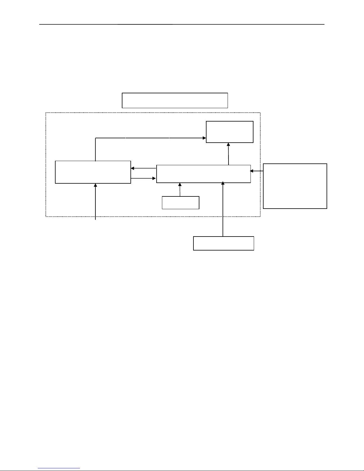
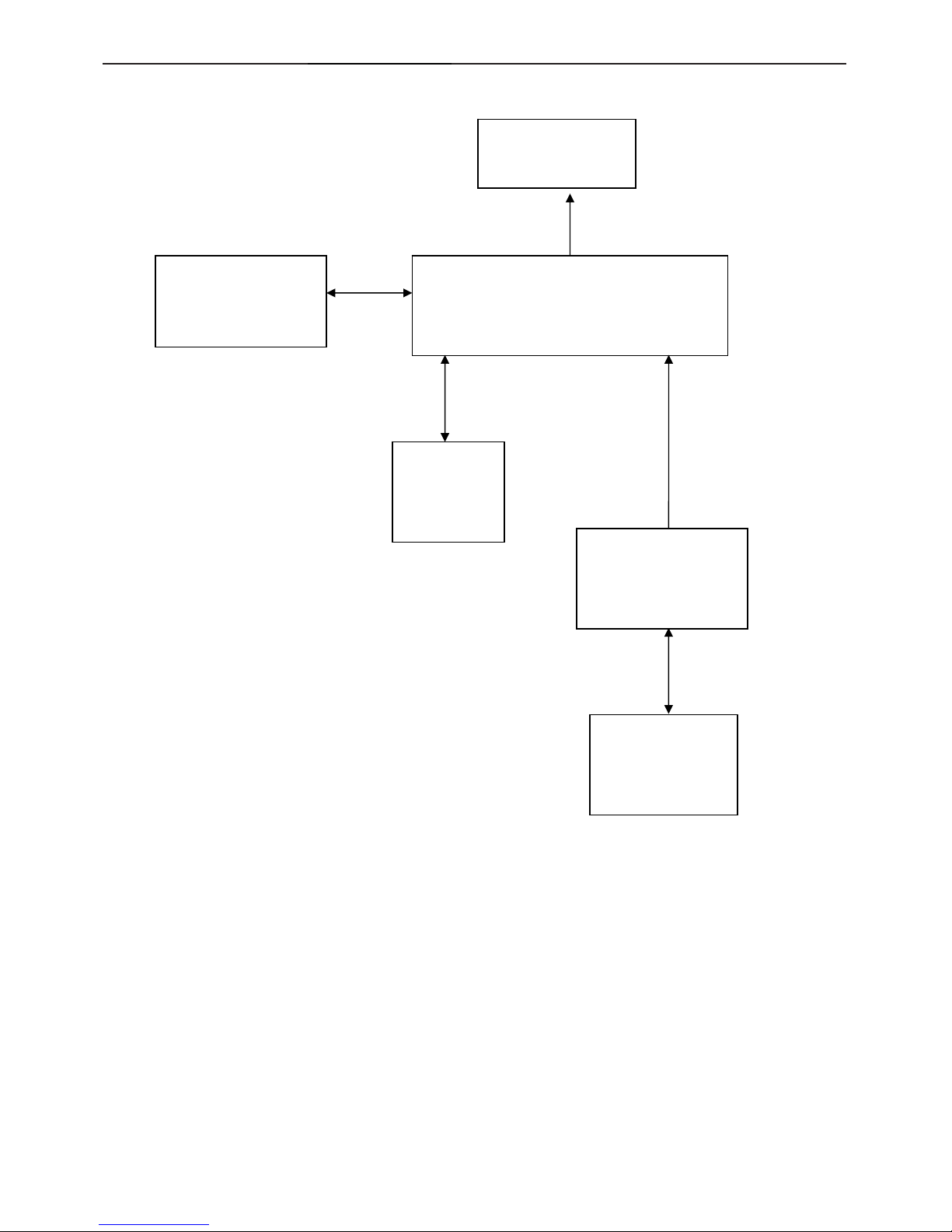
2. LCD Monitor Description
The LCD MONITOR will contain a main board, a power board, an audio board and a key board which house the flat
panel control logic, brightness control logic and DDC.
The power board will provide AC to DC Inverter voltage to drive the backlight of panel and the main board chips
each voltage.
HOST Computer
AC-IN
100V-240V
PWPC board
(Include: adapter, inverter)
Flat Panel and
CCFL backlight
Main Board
RS232 Connector
For white balance
adjustment in factory
mode
CCFL Drive.
Video signal DDC
Monitor Block
Keyboard
Page 5
17" LCD Color Monitor AOC 172V
5
3. Operating Instructions
3.1 General Instructions
Press the power button to turn the monitor on or off. The other control buttons are located at front panel of the
monitor.
By changing these settings, the picture can be adjusted to your personal preferences.
-
The power cord should be connected.
-
Connect the video cable from the monitor to the video card.
-
Press the power button to turn on the monitor, the power indicator will light up.
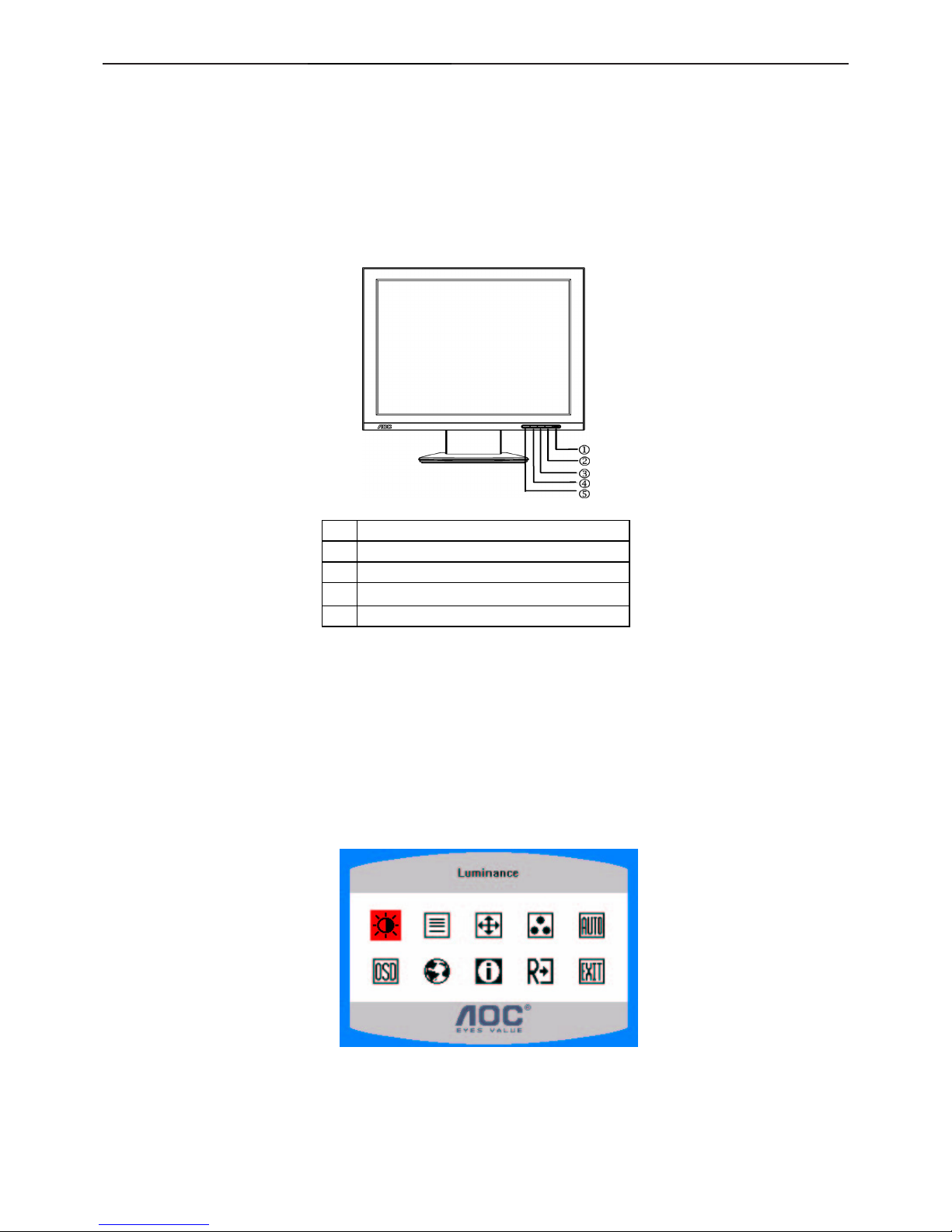
3.2 Control Buttons
1 Power Button/ Power Indicator
2. MENU / ENTER
3. Contrast
4. Brightness
5. Auto Config / Exit
3.3 Adjusting the Picture
1. Press the MENU-button to activate the OSD window.
2. Press < or > to navigate through the functions. Once the desired function is highlighted, press the
MENU-button to activate it. If the function selected has a sub-menu, press < or > again to navigate through
the sub-menu functions. Once the desired function is highlighted, press MENU-button to activate it.
3. Press < or > to change the settings of the selected function.
4. To exit and save, select the exit function. If you want to adjust any other function, repeat steps 2-3.
Page 6
17" LCD Color Monitor AOC 172V
6
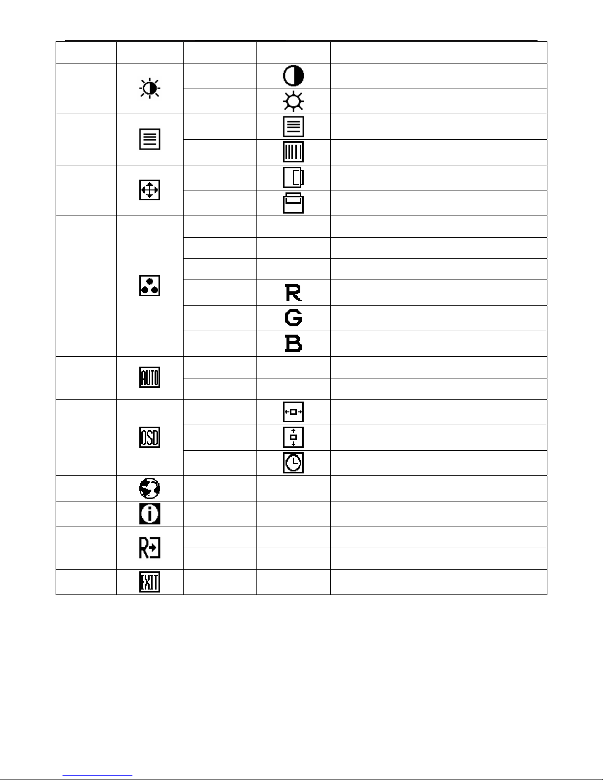
Main Menu
Item
Main Menu
Icon
Sub Menu Item Sub Menu Icon Description
Contrast
Contrast from Digital-register.
Luminance
Brightness
Backlight Adjustment
Focus
Adjust Picture Phase to reduce Horizontal-Line
noise
Image Setup
Clock
Adjust picture Clock to reduce Vertical-Line noise.
H. Position
Adjust the horizontal position of the picture.
Image
Position
V. Position
Adjust the vertical position of the picture.
Warm N/A Recall Warm from EEPROM.
Cool N/A Recall Cool from EEPROM.
sRGB N/A Recall sRGB from EEPROM.
User / Red
Red Gain from Digital-register.
User / Green
Green Gain Digital-register.
Color Temp.
User / Blue
Blue Gain from Digital-register.
Yes
N/A
A
uto Adjust the H/V Position, Focus and Clock of
picture.
Auto Config
No N/A Do not execute Auto Config, return to main menu.
H. Position
Adjust the horizontal position of the OSD.
V. Position
Adjust the vertical position of the OSD.
OSD Setup
OSD Timeout
Adjust the OSD timeout.
Language
Language
N/A
Set OSD language
Information
Information N/A
Show the resolution, H/V frequency and input port of
current input timing.
Yes N/A Clear each old status of Auto-configuration
Reset
No N/A Do not execute reset, return to main menu.
Exit
N/A N/A Exit OSD
Page 7
17" LCD Color Monitor AOC 172V
7
4. Input/Output Specification
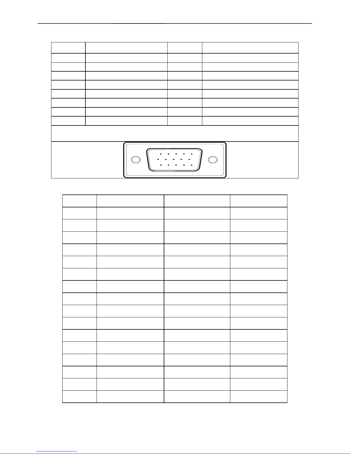
4.1 Input Signal Connector
PIN NO. DESCRIPTION PI N NO. DESCRIPTION
1. Red 9. +5V
2. Green 10. Detect Cable
3. Blue 11. RXD
4. TXD 12. DDC-Serial Data
5. Ground 13. H-Sync
6. R-Ground 14. V-Sync
7. G-Ground 15. DDC-Serial Clock
8. B-Ground
VGA connector layout
15
6
10
11 15
4.2 Factory Preset Display Modes
STANDARD
RESOLUTION
HORIZONTAL
FREQUENCY
(
kHz
)
VERTICAL
FREQUENCY
(Hz)
Dos-mode
640 × 350 31.47kHz 70Hz
Dos-mode
720 × 400 31.47kHz 70Hz
VGA
640 × 480 31.47kHz 60Hz
640 × 480 35.00kHz 66.6Hz
640 × 480 37.50kHz 75Hz
640 × 480 37.86kHz 72Hz
SVGA
800 × 600 37.879kHz 60Hz
800 × 600 46.875kHz 75Hz
800 × 600 35.16kHz 56Hz
800 × 600 48.01kHz 72Hz
832 × 624 49.725kHz 75Hz
XGA
1024 × 768 48.363kHz 60Hz
1024 × 768 56.476kHz 70Hz
1024 × 768 60.02kHz 75Hz
SXGA
1280 × 1024 64.00kHz 60Hz
1280 × 1024 80.00kHz 75Hz
Page 8
17" LCD Color Monitor AOC 172V
8
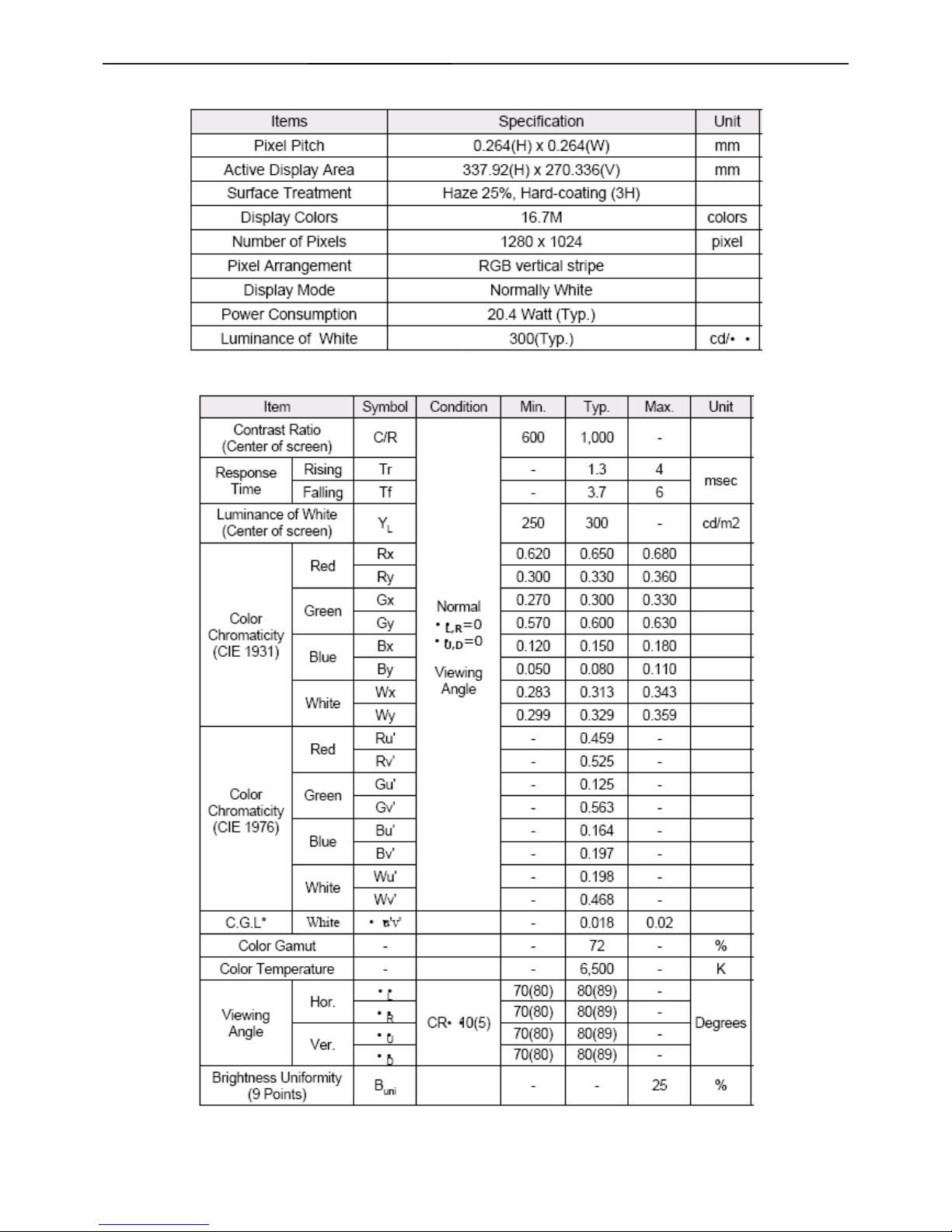
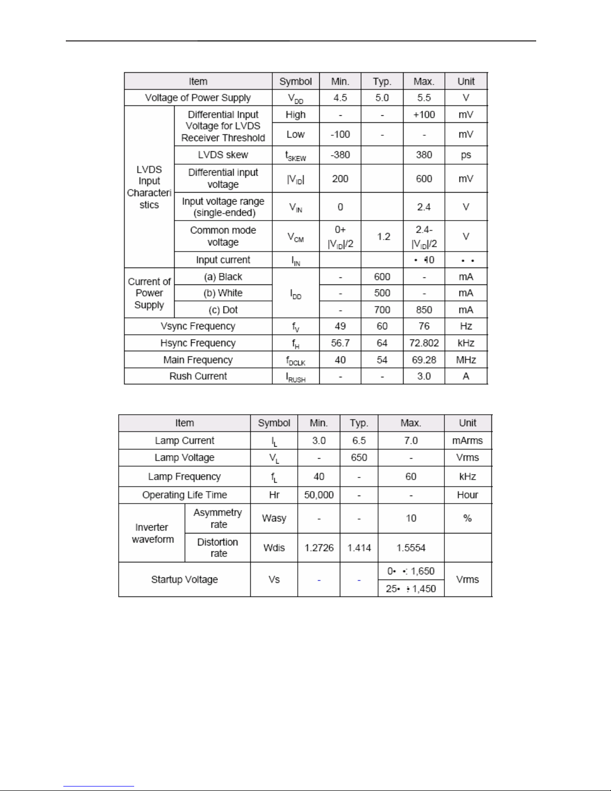
5 Panel Specification
5.1 Display Characteristics
5.2 Optical Characteristics
Page 9
17" LCD Color Monitor AOC 172V
9
5.3 Parameter guide line for CCFL Inverter
1.TFT LCD Module:
2.Back Light Unit:
Page 10
17" LCD Color Monitor AOC 172V
10
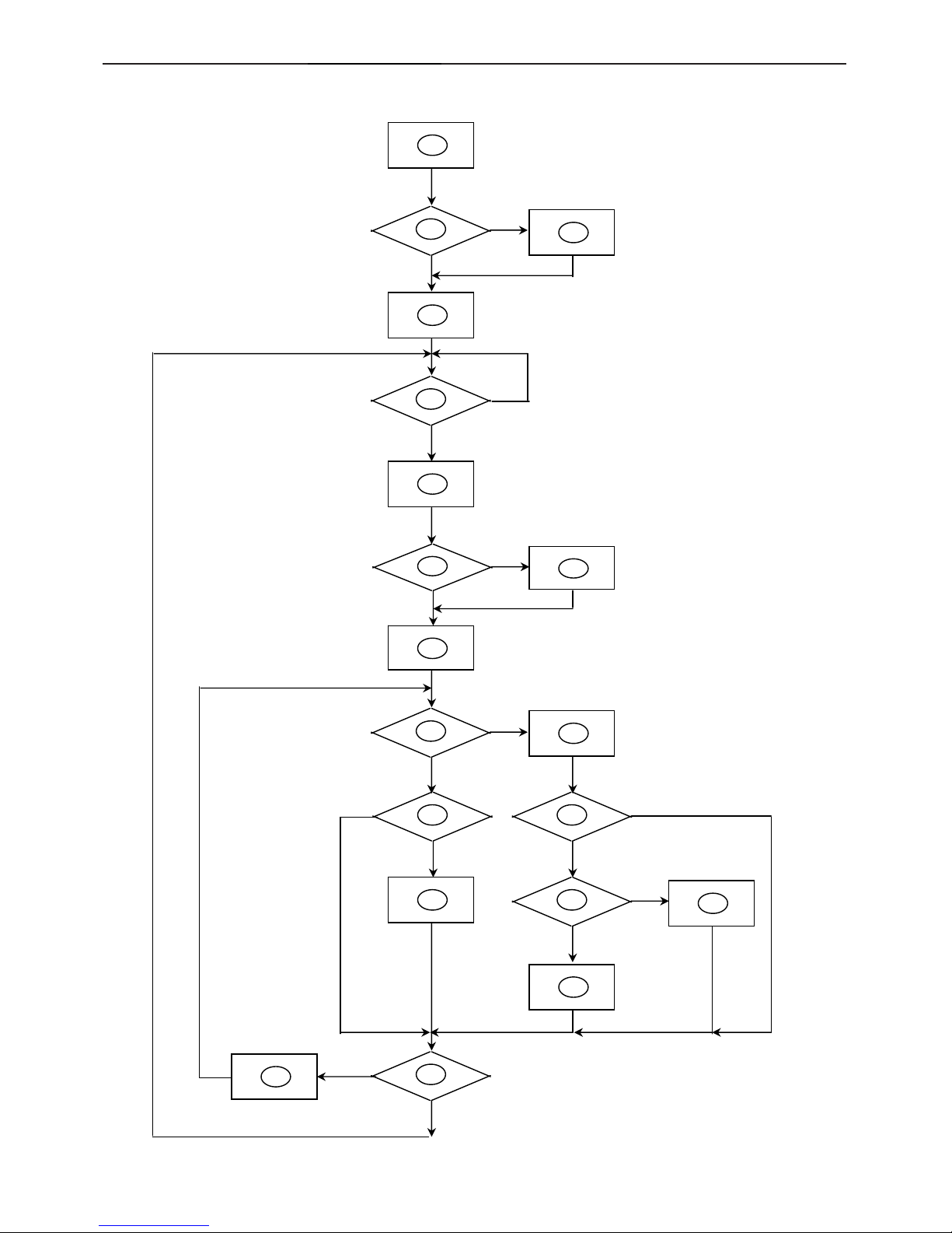
6. Block Diagram
6.1 Software Flow Chat
1
2
N
Y
5
Y
N
10
Y
N
12
Y
N
7
N
6
4
3
9
14
11
13
Y
N
15
Y
N
16
17
19
Y
N
18
Page 11

17" LCD Color Monitor AOC 172V
11
1) MCU initialize.
2) Is the EPROM blank?
3) Program the EPROM by default values.
4) Get the PWM value of brightness from EPROM.
5) Is the power key pressed?
6) Clear all global flags.
7) Are the AUTO and SELECT keys pressed?
8) Enter factory mode.
9) Save the power key status into EPROM.
Turn on the LED and set it to green color.
Scalar initializes.
10) In standby mode?
11) Update the lifetime of back light.
12) Check the analog port, are there any signals coming?
13) Does the scalar send out an interrupt request?
14) Wake up the scalar.
15) Are there any signals coming from analog port?
16) Display "No connection Check Signal Cable" message. And go into standby mode after the message
disappear.
17) Program the scalar to be able to show the coming mode.
18) Process the OSD display.
19) Read the keyboard. Is the power key pressed?
Page 12
17" LCD Color Monitor AOC 172V
12
6.2 Electric Block Diagram
6.2.1 Main Board
FLASH MEMORY
PM25LV512A (U402)
Scalar TSUM16AK
(Include: MCU, ADC, OSD etc)
(U401)
EEPROM
24C02
(U404)
H sync
V sync
RGB
DB12_SDA,
DB15_SCL
LCD Interface
(CN101)
EEPROM
24C16N
(U403)
D-Sub
Connector
(CN405)
Page 13
17" LCD Color Monitor AOC 172V
13
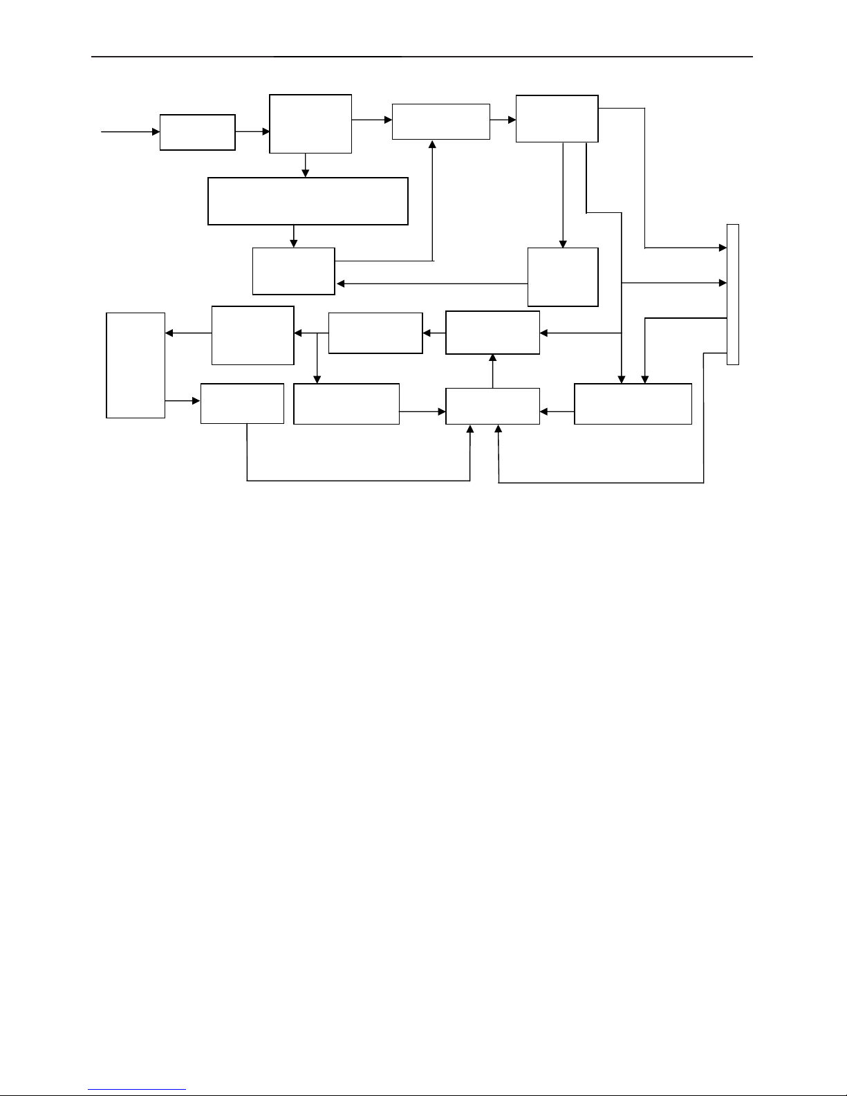
6.2.2 Inverter / Power Board
EMI filter
Bridge
Rectifier
and Filter
Start Circuit: R905、R906、
R907、R908、R909、R910
PWM
Control IC
Transformer
Over
Voltage
Protect
Rectifier
diode
AC input
5V
12V
ON/OFF Control
PWM
Control IC
Feedback
Circuit
OSC and
Output
Circuit
DC Convert
Circuit
MOSFET
Over Voltage
Protect
Lamp
ON/OFF
DIM
CN102
PWM
Page 14

17" LCD Color Monitor AOC 172V
14
7. Schematic
7.1 Main Board
VLCD
+12V
+5V
TSUM16AK SCHEMATIC
VCC3.3
VCC3.3
PB[0..5]
PC5V
+12V
VLCD_12VVLCD
B3
3.INPUT
RIN
GIN
BIN
VSYNC
GNDR
GNDG
GNDB
DET_VGA
HSYNC
SOG
B+
CLK-
DET_DVI
CLK+
R+
G+
R-
B-
G-
DDCA_SDA
DDCA_SCL
DDCD_SDA
DDCD_SCL
+5V
DDC_WP
VCC1.8
VCC5V
VLCD_12V
GPO[0..4]
XGA/SXGA LVDS OUTPUT
+5V
B5
5.PANEL INTERFACE
VLCD
PA[0..7]
PA[8..13]
ESP
PA[14..19]
PB[0..5]
PB[6..11]
GPO[0..4]
OSP
VLCD_12V
PB[12..23]
TSUM16AK
PA[0..7]
+3V3
PA[8..13]
VCC1.8
PA[14..19]
PB[6..11]
B4
4.SCALER
RIN
GIN
SOG
BIN
GNDR
GNDG
GNDB
HSYNC
VSYNC
Adj_BACKLIGHT
VCC1.8
Vcc3.3
VCTRL
PA[0..7]
PA[8..13]
R+
R-
G-
G+
B+
B-
CLK+
CLKDDCD_SDA
DDCD_SCL
DET_DVI
DDCA_SDA
DDCA_SCL
DET_VGA
on_BACKLIGHT
on_Panel
+5V
PA[14..19]
PB[0..5]
PB[6..11]
GPO[0..4]
ESP
OSP
on_PANEL_12V
PB[12..23]
+12V
DDC_WP
TOP
A
B
05Monday, May 09, 2005
Title
Size Document Number Rev
Date: Sheet
of
PB[12..23]
B2
2.POWER
on_Panel
on_BACKLIGHT
Adj_BACKLIGHT
+3V3
VCC1.8
VLCD
+5V
VCTRLPC5V
VCC5V
VCC3.3
on_PANEL_12V
VLCD_12V
+12V
+5V
Page 15

17" LCD Color Monitor AOC 172V
15
GND
R711
10K 1/16W
PC5V 3
P W M
C701
NC
R724 51K
Q705
AO3401L
+
C710
100uF/25V
VCTRL 4
VCC3.3 4
+12V
R708
10K 1/16W
C32
X
+12V
R705
4.7K 1/16W
+
C702
4.7uF/16V
Recommond to used "Blue" parts circuit
for VCC1.8V if you want to suppoert DDC
function when system power off
+5V
+5V
+12V
R709
0 1/16W
01UF
R717
10K 1/16W
1uF
R701
1K 1/16W
VLCD_12V 5
N.C
12/21 MODIFY
CN701
CONN
2
4
6
8
10
12
1
3
5
7
9
11
R715
NC
C713
0.1uF
+5V3,4on_BACKLIGHT 4
C706
0.1uF
P.S: The 1N4148 Vf=0.7V~1V can't meet
LDO spec. The BAT42, Vf is OK but the
If=200mA(forward current) can not
meet current spec.
VLCD 5
R29
R720 0 1/16W
+5V
TSUM16AK
R723 51K 1/16W
R728
NC/4K7
R727
10K 1/16W
Q704
AO3401L
R32
SOT-223
0V ~ 3.3V 4.7K
R704
100 1/16W
+
C712
100uF/25V
+5V
+3V3
+5V
Q706
PMBS3904
R729
NC/10K
U701
NC/LT1117-18
3 2
1
4
VI VO
GND
VO
For RSDS and Panel VCC=12V
D704
SMAL140
+12V 4
47
VCC5V
R714
10K 1/16W
+5V
GND
MMBT3904
R726 NC/4K7
+12V
+3V3
R707
4.7K 1/16W
C51
4K7D C
+5V
R703
2K 1/16W
4.7K
C716
0.1uF
+5V
R710 NC
on_Panel4
R31
C708
1uF
R716
NC
Q701
PMBS3904
R31
GND
+5V3,4
+5V
GND
H3
TP
123
4
5
678
9
123
4
5
678
9
+
C719
NC/10uF/16V
VCC1.8 4
VLCD
C718
0.1uF
R721
0 1/16W
H2
TP
123
4
5
678
9
123
4
5
678
9
R33
R722
NC
R731
NC
X
R730
0 1/16W
BL_ADJ
H1
TP
123
4
5
678
9
123
4
5
678
9
Q703
PMBS3904
Q4
VCC1.8
R713
NC
on_Panel_12V4
+3V3
+12V
+
C705
1uF/16V
PC5V
X
C704
NC
X
D703
BAT54C
3
1
2
Adj_BACKLIGHT
4
D704(SSM12L) Vf=0.38V and If=1A.
So when system power on, the
system loading is about 400mA
(3.3V is about 200mA and 1.8V is
about 200mA), So D35 changed
from 1N4148(or BAT42) to
SSM12L(schottky diode).
VLCD_12V
+
C703
100uF/25V
C715
0.1uF
Q702
CHT2907
C
B
E
VCC3.3
BL_ON
GND
Q707
PMBS3904
+3V3
+3V3
0V ~ 5V
R712 4.7K 1/16W
C720
NC/0.1uF
D702
1N4148
BL_ADJ(DC)
D701
1N4148
R718
NC/10K
R719
NC/10K
C714
0.1uF
1K
POWER
A
B
15Monday, May 09, 2005
Title
Size Document Number Rev
Date: Sheet
of
+5V
VCC3.3
C711
0.1uF
+5V
GND
R732
10 1/16W
U702
AIC1084-33PM
3
1
2
4
VIN
ADJ
VOUT
VOUT
R706
NC
C709
0.1uF
+5V3,4
BL_ADJ
R702
51 1/16W
1UF
TO-263
VCC3.3 4
+5V
+
C707
100uF/25V
4.7K
+5V
R725
4.7K 1/16W
+
C717
10uF/16V
Page 16

17" LCD Color Monitor AOC 172V
16
FB409 120 OHM
C446
0.1uF
VSI
C448
0.1uF
R444
10K 1/16W
GREEN-
PC5V
R462 10 1/16W
C436 0.047uF
R456 100 1/16W
DAT0-
+5V
R451
10K 1/16W
GREEN+
U405
M24C02
1
2
3
45
6
7
8
A0
A1
A2
GNDSDA
SCL
WP
VCC
C432 0.047uF
D413
BAV70
3
1
2
R470
1K 1/16W
G- 4
DCLK-
R438
75 1/16W
D404
BAV99
3
1
2
R445 100 1/16W
BLUE-
U404
M24C02
1
2
3
45
6
7
8
A0
A1
A2
GNDSDA
SCL
WP
VCC
G+ 4
DDC_WP 4
R455 100 1/16W
D420
BAV99
3
1
2
C453
0.1uF
DAT1-
DAT2-
D415
LL5232B 5.6V 5%
BLUE+
D419
BAV99
3
1
2
D426
LL5232B 5.6V 5%
C447
0.1uF
R439
75 1/16W
+5V
R466 10 1/16W
C450
0.1uF
DVI5V
R434 56 1/16W
D424
BAV99
3
1
2
D417
BAV99
3
1
2
RED+
R449
2.2K 1/16W
BIN 4
ESD_5V
GIN 4
C445
0.1uF
R473
NC
R465 10 1/16W
DAT2+
C449
0.1uF
C440 0.1uF
VGA_CON
HSYNC 4
R448
2.2K 1/16W
R441 100 1/16W
D422
BAV99
3
1
2
C443
220pF
DCLK+
R437 470 1/16W
R471
10K 1/16W
R461
10K 1/16W
C441 0.1uF
R459
10K 1/16W
+5V 2,4
DVI5V
RED-
D421
BAV99
3
1
2
C444
0.1uF
R469 10 1/16W
C434 0.047uF
D418
BAV99
3
1
2
D403
BAV99
3
1
2
SCL_VGA
C451
0.1uF
GNDG 4
GNDB 4
R454 100 1/16W
R443 100 1/16W
C433 0.047uF
DET_VGA 4
SOG 4
B+ 4
R460
10K 1/16W
R467 10 1/16W
R436 56 1/16W
GNDR 4
DDCD_SCL4
ESD_5V
VSYNC 4
CN406
JACK DVI
1
2
3
4
5
6
7
8
25
28
9
10
11
12
13
14
15
16
26
29
17
18
19
20
21
22
23
24
27
DAT2-
DAT2+
2/4shield
DAT4-
DAT4+
DDC SCL
DDC SDA
VSYNC
R
HSYNC
DAT1-
DAT1+
1/3shield
DAT3-
DAT3+
+5V
SYNC GND
HPD
G
RGB GND
DAT0-
DAT0+
0/5shield
DAT5-
DAT5+
clk shield
clk+
clk-
B
C452
0.1uF
C435 0.047uF
R468 10 1/16W
D409
MLL5232B 5.6V
DAT0+
R447 1K 1/16W
FB411 0 1/16W
D412
MLL5232B 5.6V
D414
LL5232B 5.6V 5%
R452
10K 1/16W
DAT1+
R+ 4
D407
BAV70
3
1
2
SDA_VGA
D405
BAV99
3
1
2
DDCA_SDA4
FB410 0 1/16W
DDCD_SDA4
R472
NC
R458 100 1/16W
CLK+ 4
D408
MLL5232B 5.6V
VCC5V
HSI
C454
0.1uF
R453 100 1/16W
D411
MLL5232B 5.6V
RIN 4
DDCA_SCL4
R440
75 1/16W
PC5V
C439 0.1uF
SCL_DVI
R442 100 1/16W
R- 4
D410
MLL5232B 5.6V
+5V
+5V
R435 56 1/16W
R464 10 1/16W
C438 0.047uF
R446 1K 1/16W
CLK- 4
DET_DVI 4
SDA_DVI
C437 0.047uF
INPUT
A
B
15Monday, May 09, 2005
Title
Size Document Number Rev
Date: Sheet
of
C442
33pF
DVI5V
R463 10 1/16W
R457
10K 1/16W
R450
10K 1/16W
HPD
FB412 0 1/16W
DDC_WP 4
PC5V
D425
RLZ36B
1 2
TSUM16AK
CN405
DB15
1
6
2
7
3
8
4
9
5
11
12
13
14
15
10
1716
D416
LL5232B 5.6V 5%
D423
BAV99
3
1
2
D406
MLL5232B 5.6V
B- 4
Page 17

17" LCD Color Monitor AOC 172V
17
KEY_LEFT
C424 0.1uF
PA17
KEY_MENU
KEY_B
PB9
C422
0.1uF
PB15
OSP
R421 0 1/16W
RIN3
AVDD
VCC3.3
VDVI
U406
ASM810MEURF-T
1
23
GND
RSTVCC
U401
59
56
57
54
58
55
53
63
64
51
62
61
70
72
71
73
79
21
108
32
33
109
110
111
112
113
114
118
119
120
121
122
123
124
125
126
127
107
106
105
41
47
39
40
42
43
44
45
46
48
49
3896116
67
12
104
102
11
14
68
65
66
36
37
29
50
97
69
78
20
22
23
24
27
28
30
31
35
76
77
19
100
101
98
99
93
94
91
92
89
90
9
10
15
16
17
18
2
3
5
6
7
8
128
1
80
81
88
87
86
85
84
83
82
25
26
75
74
52344
95
103
115
117
60
13
RIN0P
GIN0P
SOGIN0
BIN0P
RIN0N
GIN0N
BIN0N
HSYNC0
VSYNC0
REXT
REFP
REFM
SDO
SCK
SCZ
SDI
GPIO_P27/PWM1
PWM1/GPIO_P25
NC/LVACKM/NC
XIN
XOUT
RA1P/LVA2P/RA2
RA1N/LVA2M/RA3
RA2P/LVA1P/RA4
RA2N/LVA1M/RA5
RA3P/LVA0P/RA6
RA3N/LVA0M/RA7
CLKAP/LVB3P/LHSYNC
CLKAN/LVB3M/LVSYNC
CLKBP/LVBCKP/LCK_ODD
CLKBN/LVBCKM/LDE
NC/LVB2P/NC
NC/LVB2M/NC
BB1P/LVB1P/BB2
BB1N/LVB1M/BB3
BB2P/LVB0P/BB4
BB2N/LVB0M/BB5
NC/LVACKP/NC
GA3N/LVA3M/GA7
GA3P/LVA3P/GA6
GND
GND
RX2P
RX2N
RX1P
RX1N
AVDD_DVI
RX0P
RX0N
RXCKP
RXCKN
GND
GND
GND
VDDP
VDDC
MODE[1]
MODE[0]
VCTRL
VDDP
VDD_OTP
DDCA_SDA
DDCA_SCL
DDCD_SDA
DDCD_SCL
PWM0/GPIO_P26
AVDD_DVI
VDDC
GPIO_P15
PWM2/GPIO_P24
GPIO_P16
GPIO_P17/SAR0
GPIO_P00/SAR1
GPIO_P01/SAR2
GPIO_P06
GPIO_P07
GPIO_P13
GPIO_P14
GPIO_P16
DDCROM_SDA
DDCROM_SCL
RST
GA2P/NC/GA4
GA2N/NC/GA5
GA1P/NC/GA2
GA1N/NC/GA3
BA3P/NC/BA6
BA3N/NC/BA7
BA2P/NC/BA4
BA2N/NC/BA5
BA1P/NC/BA2
BA1N/NC/BA3
RB1P/NC/RB2
RB1N/NC/RB3
RB2P/NC/RB4
RB2N/NC/RB5
RB3P/NC/RB6
RB3N/NC/RB7
GB1P/NC/GB2
GB1N/NC/GB3
GB2P/NC/GB4
GB2N/NC/GB5
GB3P/NC/GB6
GB3N/NC/GB7
BB3P/NC/BB6
BB3N/NC/BB7
ESP
OSP
GPO0
GPO1
GPO2
GPO3
GPO4
GPO5
GPO6
GPIO_P02/SAR3
GPIO_P03
GPIO_P22
GPIO_P23
AVDD_PLL
AVDD_MPLL
AVDD_MPLL
VDDP
VDDP
VDDP
VDDC
AVDD_ADC
GND
PA18
C430
0.1uF
+5V
LED_G
GNDG3
PB[0..5]
Volume
KEY_RIGHT
R479 1K 1/16W
R404
10K 1/16W NC
+
C408
10uF/16V
VSYNC3
AUDIO_STBY
PB18
R433 NC
VCC3.3
AUDIO_MUTE
OUT-R-
+5V
adj_BACKLIGHT 2
VMPLL
KEY_B
CN403
CONN
2
4
6
8
10
12
14
16
1
3
5
7
9
11
13
15
B-3
FB407
600 OHM
PB20
B+3
R474
3.9K 1/16W
PB[6..11]
R414
120 1/16W
G+3
OUT-R+
PB5
WP
R422 4.7K 1/16W
R485
10K 1/16W
PA[8..13] 5CLK-3
G-3
GIN3
BIN3
KEY_A
CN404
CONN
2
4
6
8
10
12
14
1
3
5
7
9
11
13
C409
0.1uF
U403
AT24C16N-10SC-2.7
1
2
3
45
6
7
8
A0
A1
A2
GNDSDA
SCL
WP
VCC
CLK+3
VCC3.3
PA0
PA16
PA5
R406
10K 1/16W
VCC3.3
PA1
VCC3.32
VCC3.3
KEY1
PA[14..19]
GNDR3
on_PANEL_12V 2
VCC3.3
LED_G
KEY A
PA7
R482
NC
PA3
R424
10K 1/16W
R477 1K 1/16W
FB401
600 OHM
VDDC
VCC3.3
PA12
PA13
PB12
FB406
600 OHM
VMPLL
PA14
FB402
600 OHM
R417 20K 1/16W
R426
10K 1/16W
LED_A
PB[0..5] 5
C411
0.1uF
R429 100 1/16W
POWER
VCC3.3
PB[6..11] 5
VCC1.8
PA10
DDCA_SCL3
C429
0.1uF
GND
PB1
PA[0..7] 5
KEY2
R484
10K 1/16W
Q401
PMBS3906
PA[14..19] 5
VCTRL 2
PB[12..23]
R416
10K 1/16W
VCC3.32
KEY_MENU
X401
14.318MHz
+5V 2,3
R487
10K 1/16W
OUT-L-
KEY_A
PB16
U402
SST25VF010-20-4C-SAE
1
2
3
4 5
6
7
8
CE#
SDO
WP#
VSS SDI
SCK
HOLD#
VDD
DDCA_SDA3
PB8
C415
0.1uF
AVDD
OUT-L+
C421 22pF
VDVI
R431 0 1/16W
Q403
PMBS3906
R481
NC
LED_A
PB2
PA4
PB0
C420
0.1uF
C414
0.1uF
C405
0.1uF
ESP 5
DDCD_SDA3
GPO4
VCC3.32
KEY_LEFT
PB19
C616
NC
Q402
PMBS3904
R409
120 1/16W
Q404
PMBS3904
FB404
600 OHM
GNDB3
VDDC
PB10
WP
ESP
PB23
C407
0.1uF
R413
10K 1/16W
C412
0.1uF
P[0..7]
R415
10K 1/16W
R475
3.9K 1/16W
C428
0.1uF
OUT-L+
SCALER
A
C
15Thursday, May 12, 2005
Title
Size Document Number Rev
Date: Sheet
of
VPLL
KEY_C
AUDIO_STBY
R478 1K 1/16W
R412
10K 1/16W
RSDS/LVDS/TTL
PB11
GPO[0..4]
C426
0.1uF
R411 100 1/16W
+5V
C413
0.1uF
R423 4.7K 1/16W
Option
TSUM16AK
POWER
R483
NC
PA9
R418 100 1/16W
R488 NC
HSYNC3
KEY_AUTO
PA11
R427 100 1/16W
DDCD_SCL3
VCC3.3
GPO[0..4] 5
PB[12..23] 5
+12V 2
PA19
R490
10K 1/16W
C427
0.1uF
PA8
C401
0.1uF
OSP 5
on_BACKLIGHT 2
OUT-R-
C404
0.1uF
R480 1.5K 1/16W
C406
0.1uF
DDC_WP 3
LED_A
PB3
PB22
PB6
+
C418
10uF/16V NC
VCC3.3
R420 100 1/16W
SOG3
GPO1
+12V
C417
0.1uF
R408
10K 1/16W
VDDP
KEY_RIGHT
R486
NC
KEY1
PB7
PB17
PB13
PA2
D401
RLZ36B
1 2
R403 390 1%
on_PANEL 2
VDDP
PB4
VCC3.32
VCC3.3
FB408
600 OHM
R419 0 1/16W
D402
RLZ36B
1 2
TSUM16AK
OUT-R+
C423 22pF
VCC1.82
POWER
GPO3
PB14
FB405
600 OHM
R425
10K 1/16W
+
C403
4.7uF/16V
+5V 2,3
VCC3.3
GPO0
C425
0.1uF
Q405
NC
E
B
C
R407 NC
FB403
600 OHM
DET_VGA 3
R+3
KEY_AUTOVolume
+5V
R476 1K 1/16W
+5V
LED_G
AUDIO_MUTE
PA15
Reset
Circuit
R432 0 1/16W
GPO2
PB21
AVDD
VPLL
C431
NC
OUT-L-
R430
1K 1/16W
R405
22K 1/16W
R-3
KEY2
KEY_C
R489
10K 1/16W
VCC3.32
C410
0.1uF
VCC3.3
PA[8..13]
R428 100 1/16W
VCC3.3
PA6
C419
0.1uF
C416
0.1uF
R410 NC
DET_DVI 3
Page 18

17" LCD Color Monitor AOC 172V
18
BB1N
GA1N
CN102
IL-FHR-B50S-HF (JAE)
1
2
3
4
5
6
7
8
9
10
11
12
13
14
15
16
17
18
19
20
21
22
23
24
25
26
27
28
29
30
31
32
33
34
35
36
37
38
39
40
41
42
43
44
45
46
47
48
49
50
GPO0
GB2P
GA2PPA10
3.3V
RP1
BR2N
B2P
BB2N
RA3P
RA1N
PA3
PA[0..7]4
RA2P
VLCD2
LVDS Panel
RA2P
PA2
FG0N
CN7
RB3N
PB[6..11]
BG1P
CLKAP
FCLKN
X
VLCD RXE1+
PA7
GPOO3
FB1N
CN101
CONN
2
4
6
8
10
12
14
16
18
20
22
24
1
3
5
7
9
11
13
15
17
19
21
23
0R
NC
GB2P
RB3P
RXOC+
FB1P
B1P
GB2N
LVB0P
PA17
R102 NC/0
GPO1
LVACKP
PA8
LVB1PRXO1-
PB[12..23]4
VLCD
RB3N
PB14
PB[0..5]4
Innolux 17"
PB3
LVA2M
PA6
PA4
0R
PB0
PA[8..13]
BB3P
BA3P
GA2P
R103 NC
CPT 15
GPO4
RXO0+
FR1N
LVA1M
PA12
BG0N
LVB2M
PA6
LVA0M
INNOLUX 15
V
RXEC+
LVA2M
R97
RB2N
RB2P
RXE3-
LVA3M
C106
NC
PA15
PA13
0R
RA3N
BA2P
PB20
GA1P
R109 NC
PB12
BA1P
GPOO4
GPO[0..4]4
0R
CLKAN
CLKAP
FB0N
VLCD 2
NC
NC
PB2
RXE0-
RXO0-
CPT 17
BG2P
BCLKP
RXEC-
BA2P
C103
NC
NC
R89
LVB3P
RA1P
C102
NC
CN103
IL-FHR-B30S-HF (JAE)
1
2
3
4
5
6
7
8
9
10
11
12
13
14
15
16
17
18
19
20
21
22
23
24
25
26
27
28
29
30
BB3N
GA3N
R110 NC
LVBCKP
FB2P
GPOO1
0R
NC
NC
RB1P
RB2P
PA5
R88
BG2N
LP
3.3V
NC
NC
R91
B0N
0R
PA[0..7]
X
LVB3P
PA12
3.3V
PB8
PB9
PB13
PB18
GPOO0
LVA0P
RXO3-
PB23
PA[0..7]4
0R
BA1N
FR1P
C107
NC
NC
12V
RA2N
CLKBN
R108 NC
NC
PB7
PA[14..19]4
R90
V
B1N
BR1P
BB3P
STV2
FB2N
NC
PA18
LVB3M
FG0P
NC
GB2N
RXO2+
RXOC-
GPOO2
PA1
LVB1M
RA1P
GA2N
RB1N
LVB3M
0R
R92
V
GA3P
BB2P
NC
STV1
QDI 17
B0P
PA11
BA3N
STH
GB3P
LVA3P
LVB1P
FB0P
0R
NC
LVA0M
GA3N
VLCD_12V
GPOO0
12V
R95
X
PB1
PA16
PA9
PA19
FG1P
NC
GB1N
GB3P
LVACKM
BA1N
BR0N
NC
X
PANEL INTERFACE
A
B
15Monday, May 09, 2005
Title
Size Document Number Rev
Date: Sheet
of
RXO1+
CLKBN
PB17
LVB0M
LVA1P
RA3N
PA3
FG1N
GPOO4
GA3P
5V
CN8
PB21
C105
NC
LVA3P
B2N
RP101 NC
1
2
3
4 5
6
7
8
PA14
PB18
0R
BB3N
BB1N
X
GPO[0..4]
PB[12..23]
NC
R93
PB16
NC
0R 0R
GB3N
PB14
CLKBP
LVA0P
BB2P
LVB2P
RXE2-
LVA2P
GA1N
PA13
PA0
PA5
PB19
GA2N
5V
PB10
LVB0M
RXO2-
LVA1M
C101
NC
NC
GPOO3
NC
LVA1P
RA1N
LVA3M
VLCD_12V2
RSDS Panel V
RB2N
BB1P
BR0P
FCLKP
FG2N
3.3V
LVB2M
PB19
PA7
BA1P
0R
BG0P
LVB1M
PB20
V
GPO2
PB4
LVACKP
PB12
PB[12..23]4
NC
GPO3
PB[0..5]
RA2N
FR2P
0R
0R
FR2N
FR0N
3.3V
RXO3+
PB22
BG1N
PB13
ESP
PB6
RB3P
BR1N
POL
NC
5V
OSP
RXE1-
PB21
X
LVA2P
LVBCKM
12V
3.3V
3.3V
LVACKM
GPOO2
HannStar 15
LG 15
RXE3+
BA2N
R101 NC/0
3.3V
Table 1
RB1P
R105 NC
3.3V
V
BR2P
GB1P
GB1N
BB2N
C104
NC
PA[8..13]4
12V
NC
PB11
BB2N
LVB2P
FR0P
R96
PB5
OSP4
AU 17
PA2
BB1P
FG2P
Table 1
X
GB1P
RXE2+
LVBCKM
BA3P
BCLKN
PA[0..7]
PB15
GPOO1
GB3N
LVBCKP
PB[12..23]
ESP4
0RV
TSUM16AK
LVB0P
CLKAN
BA3N
X
RB1N
PA4
BA2N
RA3P
GA1P
3.3V
0R
CN9
V
PB15
OE
R107 NC
R106 NC
RXE0+
CLKBP
CLKV
R104 NC
PB[6..11]4
NC
R94
NC
Page 19

17" LCD Color Monitor AOC 172V
19
7.2 Power Board
Page 20

17" LCD Color Monitor AOC 172V
20
Page 21

17" LCD Color Monitor AOC 172V
21
8. PCB Layout
8.1 Main Board
Page 22

17" LCD Color Monitor AOC 172V
22
Page 23

17" LCD Color Monitor AOC 172V
23
Page 24

17" LCD Color Monitor AOC 172V
24
8.2 Power Board
Page 25

17" LCD Color Monitor AOC 172V
25
Page 26

17" LCD Color Monitor AOC 172V
26
Page 27

17" LCD Color Monitor AOC 172V
27
8.3 Key Board
Page 28

17" LCD Color Monitor AOC 172V
28
9. Maintainability
9.1 Equipments and Tools Requirement
1. Voltmeter.
2. Oscilloscope.
3. Pattern Generator.
4. DDC Tool with an IBM Compatible Computer.
5. Alignment Tool.
6. LCD Color Analyzer.
7. Service Manual.
8. User Manual.
Page 29

17" LCD Color Monitor AOC 172V
29
9.2 Trouble Shooting
9.2.1 Main Board
1. NO SCREEN APPEAR
No power
No power
Press power key and look
if the picture is normal
Please reinsert and make sure
the AC of 100-240 is normal
Measure U702 PIN2=3.3V
Reinsert or check the
power section
X401 oscillate waveforms
are normal
Measure CN701 PIN5/6=12V?
Measure CN701 PIN9/10=5V?
Replace U401
Replace X401
OK
OK
OK
NG
NG
NG
NG
Check power
section
NG
OK
Replace U702
Page 30

17" LCD Color Monitor AOC 172V
30
No picture (LED orange)
No picture
OK
OK
NG
NG
Measure U401 PIN28=3.3V
Replace U401
X401 oscillate waveforms are
normal
Replace X401
Check if the sync signal from computer
is output and video cable is connected
normally
Input the sync signal of
computer, or change the
cable
Replace U401
NG
OK
Page 31

17" LCD Color Monitor AOC 172V
31
9.2.2 Power Board
1. No Power
Check CN102 pin12 = 12V
Check AC line volt 110V or 220V
Check AC input
Check the voltage of C905(+)
Check bridge rectified circuit and F901 circuit
Check start voltage for the pin3 of IC901
Check R906,R907 and Change IC901
NG
Check the auxiliary voltage is bigger than
10V and smaller than 20V
1) Check IC901
2) Check IC904 OVP circuit
OK
OK
NG
Check T901,D910,D912,ZD902
OK
Check IC901 pin8 PWM wave
OK
Check IC901
NG
NG
NG
OK
NG
Page 32

17" LCD Color Monitor AOC 172V
32
2. W/LED No Backlight
Check CN102 pin12 =12V
NG
OK
Check adapter or MB
Check ON/OFF signal
Check Interface board
NG
OK
Check U201 pin9=12V
NG
OK
Change Q201 or Q202
NG
OK
Change U201
Check D201(-), D202(-) have the output of square wave at short time.
NG
OK
Check Q205,Q206,Q207,Q208
NG
Check the output of PT201,PT202
Check Q209,Q210,Q211,Q212
Check connecter & lamp
OK
NG
Change PT201,PT202
OK
Check the resonant wave of pin2 & pin5 for PT201,PT202
Check U201 PIN10,7 have the output of square wave at short
Page 33

17" LCD Color Monitor AOC 172V
33
OSD is unstable or not working
Is Key Pad Board connecting normally ?
Connect Key Pad Board
Is Button Switch normally ?
Replace Button Switch
Y
N
N
Is Key Pad Board normally ?
Replace Key Pad Board
Y
N
Y
Check Main Board
9.2.3 Key Board
Page 34

17" LCD Color Monitor AOC 172V
34
10. White- Balance, Luminance Adjustment
Approximately 30 minutes should be allowed for warm up before proceeding White-Balance adjustment.
1. How to do the Chroma-7120 MEM. Channel setting
A. Reference to chroma 7120 user guide
B. Use “ SC” key and “ NEXT” key to modify x, y, Y value and use “ID” key to modify the
TEXT description Following is the procedure to do white-balance adjust
2. Setting the color temp. you want
A. MEM.CHANNEL 3 (7800 color):
7800 color temp. parameter is x = 296 ±20, y = 311 ±20, Y = 180 cd/m
2 ,
B. MEM.CHANNEL 4 (6500 color):
6500 color temp. parameter is x = 313±20, y = 329 ±20, Y =180 cd/m2
3. Into factory mode of 172V
Turn on power, press the MENU button, pull out the power cord, and then plug the power cord. Then the factory
OSD will be at the left top of the panel.
4. Bias adjustment:
Set the Contrast
to 50; Adjust the Brightness to 90.
5. Gain adjustment:
Move cursor to “-F-” and press MENU key
A. Adjust C2 (7800) color-temperature
1. Switch the Chroma-7120 to RGB-Mode (with press “MODE” button)
2. Switch the MEM. Channel to Channel 3 (with up or down arrow on chroma 7120)
3. The LCD-indicator on chroma 7120 will show x = 296 ±20, y = 311 ±20, Y =180 cd/m
2
4. Adjust the RED of color1 on factory window until chroma 7120 indicator reached the value R=100
5. Adjust the GREEN of color1 on factory window until chroma 7120 indicator reached the value G=100
6. Adjust the BLUE of color1 on factory window until chroma 7120 indicator reached the value B=100
7. Repeat above procedure (item 4,5,6) until chroma 7120 RGB value meet the tolerance =100±5
B. Adjust C1 (6500) color-temperature
1. Switch the chroma-7120 to RGB-Mode (with press “MODE” button)
2. Switch the MEM.channel to Channel 4(with up or down arrow on chroma 7120)
3. The LCD-indicator on chroma 7120 will show x = 313 ±20, y = 329 ±20, Y = 180 cd/m
2
4. Adjust the RED of color3 on factory window until chroma 7120 indicator reached the value R=100
5. Adjust the GREEN of color3 on factory window until chroma 7120 indicator reachedthe value G=100
6. Adjust the BLUE of color3 on factory window until chroma 7120 indicator reached the value B=100
7. Repeat above procedure (item 4,5,6) until chroma 7120 RGB value meet the tolerance =100±5
C. Turn the Power-button off to quit from factory mode.
Page 35

17" LCD Color Monitor AOC 172V
35
11. Monitor Exploded View
Page 36

17" LCD Color Monitor AOC 172V
36
12. BOM List
T78SM5NCARSPNNE
Location Part No. Description
CBPC7SM5AOH MAIN BOARD
KEPC780KAOCJP KEY BOARD
PWPC1742CPE1 POWER BOARD
15G6165SAM 3A MAIN FRAME
26G 800504 3H BARCODE
40G 58162435A MANUAL LABEL
44G3749 1 EPS(L)
44G3749 2 EPS(R)
50G 600 2 HANDLE1
50G 600 3 HANDLE2
52G 1185 MIDDLE TAPE
52G 1186 SMALL TAPE
52G6025 11737 INSULATE SHEET
85G6108 1 SHIELD
89G 715HAA D2 SIGNAL CABLE
89G404A15N YH POWER CORD
95G8018 30E15 LVDS CABLE 30P-24P 150
D1G1730 8120 SCREW
M1G 330 4120 SCREW
M1G1740 6120 SCREW
M1G1740 8120 SCREW
Q1G 330 8120 SCREW 3X8mm
705GH7K0F34029 ASS'Y
750GLS70U315CN PANEL LTM170EU-L31 8TM
H33G6246 KG L HINGE COVER
H34G6171 KG 1L BACK COVER
H34G6177 KGA1L LOGO COVER
H40G 17N61514C 172V ID label
H41G170061512B 172V MANUAL
H44G3749615 7C CARTON
H45G 87 1 2H R PE BAG FOR MONITOR
Q45G 76 28 H A PE BAG FOR MANUAL
Q52G6020 68 AOC PROTECT FILM
CN701 33G8027 12 WAFER 2*6P 2.0MM R/A
CN403 33G8027 16 WAFER 16PIN 2.0mm DIP
CN101 33G8043 24 H WAFER
40G 45762412B CBPC LABEL
C710 67G215V101 4N ELCAP 100UF +-20% 25V 1
C712 67G215V101 4N ELCAP 100UF +-20% 25V 1
C408 67G305V100 3P ELCAP 10UF +-20% 16V 10
C717 67G305V100 3P ELCAP 10UF +-20% 16V 10
C403 67G305V479 3P ELCAP 4.7UF +-20% 16V 1
C702 67G305V479 3P ELCAP 4.7UF +-20% 16V 1
CN405 88G 35315F HD D-SUB CONN F ATTACHED
X401 93G 22 53 H 14.31818MHZ/30PF/49US
U401 56G 562100 TSUM16AK
U702 56G 563 7 AIC1084-33PM
U406 56G 643 20 RESET_4.38V_G690H438T73
U404 56G1133 34 M24C02-WMN6TP
U403 56G1133 56 M24C16-WMN6TP
U402 56G1133716 PM25LV512A-100SCE
Q702 57G 417 17 T PZT2907A
Q401 57G 417517 LMBT3906LT1G SOT-23 BY
Page 37

17" LCD Color Monitor AOC 172V
37
Q403 57G 417517 LMBT3906LT1G SOT-23 BY
Q402 57G 417518 LMBT3904LT1G SOT-23 BY
Q701 57G 417518 LMBT3904LT1G SOT-23 BY
Q703 57G 417518 LMBT3904LT1G SOT-23 BY
Q706 57G 417518 LMBT3904LT1G SOT-23 BY
Q704 57G 763 1 AO3401L SOT23 BY AOS(A1
FB410 61G0603000 RST CHIPR 0 OHM +-5% 1/
FB411 61G0603000 RST CHIPR 0 OHM +-5% 1/
FB412 61G0603000 RST CHIPR 0 OHM +-5% 1/
R419 61G0603000 RST CHIPR 0 OHM +-5% 1/
R421 61G0603000 RST CHIPR 0 OHM +-5% 1/
R720 61G0603000 RST CHIPR 0 OHM +-5% 1/
R721 61G0603000 RST CHIPR 0 OHM +-5% 1/
R411 61G0603101 RST CHIPR 100 OHM +-5%
R418 61G0603101 RST CHIPR 100 OHM +-5%
R420 61G0603101 RST CHIPR 100 OHM +-5%
R427 61G0603101 RST CHIPR 100 OHM +-5%
R428 61G0603101 RST CHIPR 100 OHM +-5%
R429 61G0603101 RST CHIPR 100 OHM +-5%
R441 61G0603101 RST CHIPR 100 OHM +-5%
R442 61G0603101 RST CHIPR 100 OHM +-5%
R443 61G0603101 RST CHIPR 100 OHM +-5%
R445 61G0603101 RST CHIPR 100 OHM +-5%
R453 61G0603101 RST CHIPR 100 OHM +-5%
R454 61G0603101 RST CHIPR 100 OHM +-5%
R488 61G0603101 RST CHIPR 100 OHM +-5%
R704 61G0603101 RST CHIPR 100 OHM +-5%
R446 61G0603102 RST CHIPR 1KOHM +-5% 1/
R447 61G0603102 RST CHIPR 1KOHM +-5% 1/
R476 61G0603102 RST CHIPR 1KOHM +-5% 1/
R477 61G0603102 RST CHIPR 1KOHM +-5% 1/
R701 61G0603102 RST CHIPR 1KOHM +-5% 1/
R406 61G0603103 RST CHIPR 10KOHM +-5% 1
R408 61G0603103 RST CHIPR 10KOHM +-5% 1
R412 61G0603103 RST CHIPR 10KOHM +-5% 1
R413 61G0603103 RST CHIPR 10KOHM +-5% 1
R415 61G0603103 RST CHIPR 10KOHM +-5% 1
R416 61G0603103 RST CHIPR 10KOHM +-5% 1
R424 61G0603103 RST CHIPR 10KOHM +-5% 1
R425 61G0603103 RST CHIPR 10KOHM +-5% 1
R426 61G0603103 RST CHIPR 10KOHM +-5% 1
R444 61G0603103 RST CHIPR 10KOHM +-5% 1
R452 61G0603103 RST CHIPR 10KOHM +-5% 1
R487 61G0603103 RST CHIPR 10KOHM +-5% 1
R708 61G0603103 RST CHIPR 10KOHM +-5% 1
R711 61G0603103 RST CHIPR 10KOHM +-5% 1
R714 61G0603103 RST CHIPR 10KOHM +-5% 1
R717 61G0603103 RST CHIPR 10KOHM +-5% 1
R727 61G0603103 RST CHIPR 10KOHM +-5% 1
R409 61G0603121 RST CHIPR 120 OHM +-5%
R414 61G0603121 RST CHIPR 120 OHM +-5%
R703 61G0603202 RST CHIPR 2KOHM +-5% 1/
R417 61G0603203 RST CHIPR 20KOHM +-5% 1
R448 61G0603222 RST CHIPR 2.2KOHM +-5%
R449 61G0603222 RST CHIPR 2.2KOHM +-5%
R403 61G0603390 0F RST CHIPR 390 OHM +-1%
Page 38

17" LCD Color Monitor AOC 172V
38
R474 61G0603392 RST CHIPR 3.9KOHM +-5%
R475 61G0603392 RST CHIPR 3.9KOHM +-5%
R437 61G0603471 RST CHIPR 470 OHM +-5%
R405 61G0603472 RST CHIPR 4.7KOHM +-5%
R422 61G0603472 RST CHIPR 4.7KOHM +-5%
R423 61G0603472 RST CHIPR 4.7KOHM +-5%
R450 61G0603472 RST CHIPR 4.7KOHM +-5%
R451 61G0603472 RST CHIPR 4.7KOHM +-5%
R705 61G0603472 RST CHIPR 4.7KOHM +-5%
R707 61G0603472 RST CHIPR 4.7KOHM +-5%
R712 61G0603472 RST CHIPR 4.7KOHM +-5%
R725 61G0603472 RST CHIPR 4.7KOHM +-5%
R702 61G0603510 RST CHIPR 51 OHM +-5% 1
R723 61G0603513 RST CHIPR 51KOHM +-5% 1
R434 61G0603560 RST CHIPR 56 OHM +-5% 1
R435 61G0603560 RST CHIPR 56 OHM +-5% 1
R436 61G0603560 RST CHIPR 56 OHM +-5% 1
R438 61G0603750 RST CHIPR 75 OHM +-5% 1
R439 61G0603750 RST CHIPR 75 OHM +-5% 1
R440 61G0603750 RST CHIPR 75 OHM +-5% 1
C401 65G0603104 32 CHIP 0.1UF 50V X7R
C404 65G0603104 32 CHIP 0.1UF 50V X7R
C405 65G0603104 32 CHIP 0.1UF 50V X7R
C406 65G0603104 32 CHIP 0.1UF 50V X7R
C407 65G0603104 32 CHIP 0.1UF 50V X7R
C409 65G0603104 32 CHIP 0.1UF 50V X7R
C410 65G0603104 32 CHIP 0.1UF 50V X7R
C411 65G0603104 32 CHIP 0.1UF 50V X7R
C412 65G0603104 32 CHIP 0.1UF 50V X7R
C413 65G0603104 32 CHIP 0.1UF 50V X7R
C414 65G0603104 32 CHIP 0.1UF 50V X7R
C415 65G0603104 32 CHIP 0.1UF 50V X7R
C416 65G0603104 32 CHIP 0.1UF 50V X7R
C417 65G0603104 32 CHIP 0.1UF 50V X7R
C419 65G0603104 32 CHIP 0.1UF 50V X7R
C420 65G0603104 32 CHIP 0.1UF 50V X7R
C422 65G0603104 32 CHIP 0.1UF 50V X7R
C424 65G0603104 32 CHIP 0.1UF 50V X7R
C426 65G0603104 32 CHIP 0.1UF 50V X7R
C427 65G0603104 32 CHIP 0.1UF 50V X7R
C428 65G0603104 32 CHIP 0.1UF 50V X7R
C429 65G0603104 32 CHIP 0.1UF 50V X7R
C430 65G0603104 32 CHIP 0.1UF 50V X7R
C439 65G0603104 32 CHIP 0.1UF 50V X7R
C440 65G0603104 32 CHIP 0.1UF 50V X7R
C441 65G0603104 32 CHIP 0.1UF 50V X7R
C444 65G0603104 32 CHIP 0.1UF 50V X7R
C709 65G0603104 32 CHIP 0.1UF 50V X7R
C711 65G0603104 32 CHIP 0.1UF 50V X7R
C713 65G0603104 32 CHIP 0.1UF 50V X7R
C714 65G0603104 32 CHIP 0.1UF 50V X7R
C715 65G0603104 32 CHIP 0.1UF 50V X7R
C718 65G0603104 32 CHIP 0.1UF 50V X7R
C708 65G0603105 22 CAP 0603 1UF +-10% 25V
C421 65G0603220 31 CAP 0603 22PF 50V NPO
C423 65G0603220 31 CAP 0603 22PF 50V NPO
Page 39

17" LCD Color Monitor AOC 172V
39
C443 65G0603221 32 CHIP 220PF 50V X7R
C425 65G0603224 22 CAP 0603 0.22UF +-10% 2
C442 65G0603330 31 CAP 0603 33PF +-5% 50V
C432 65G0603473 32 CAP 0603 0.047UFK 50V X
C433 65G0603473 32 CAP 0603 0.047UFK 50V X
C434 65G0603473 32 CAP 0603 0.047UFK 50V X
C435 65G0603473 32 CAP 0603 0.047UFK 50V X
C436 65G0603473 32 CAP 0603 0.047UFK 50V X
C437 65G0603473 32 CAP 0603 0.047UFK 50V X
C438 65G0603473 32 CAP 0603 0.047UFK 50V X
FB401 71G 56Z601 CHIP BEAD 600 OHM 0805
FB402 71G 56Z601 CHIP BEAD 600 OHM 0805
FB403 71G 56Z601 CHIP BEAD 600 OHM 0805
FB404 71G 56Z601 CHIP BEAD 600 OHM 0805
FB405 71G 56Z601 CHIP BEAD 600 OHM 0805
FB406 71G 56Z601 CHIP BEAD 600 OHM 0805
FB409 71G 59B121 TB160808B
D406 93G 39147SEM ZMM5V6ST
D408 93G 39147SEM ZMM5V6ST
D409 93G 39147SEM ZMM5V6ST
D410 93G 39147SEM ZMM5V6ST
D411 93G 39147SEM ZMM5V6ST
D412 93G 39147SEM ZMM5V6ST
D407 93G 64 42 P BAV70 SOT-23
D702 93G 6432P LL4148
D403 93G 6433P BAV99
D404 93G 6433P BAV99
D405 93G 6433P BAV99
D401 93G 39S 45 T RLZ36B BY ROHM
D402 93G 39S 45 T RLZ36B BY ROHM
D701 93G 64S700PAN DIODE LLSD103A
D704 93G1004 3 SS14
715G1558 3 2 MAIN BOARD PCB
SW101 77G 602 1 CJ TACT SWITCH TSVB-2
SW102 77G 602 1 CJ TACT SWITCH TSVB-2
SW103 77G 602 1 CJ TACT SWITCH TSVB-2
SW104 77G 602 1 CJ TACT SWITCH TSVB-2
SW105 77G 602 1 CJ TACT SWITCH TSVB-2
DP103 81G 12 1F GP LED
JP101 95G8014 16E01 WIRE HARNESS
715G1412 3 KEY BOARD PCB
L203 S73G17430VA TRANSFORMER
L204 S73G17430VA TRANSFORMER
L902 S73L17426VG COMMON CHOKE
PT201 S80LL15T7VG TRANSFORMER
PT202 S80LL15T7VG TRANSFORMER
CN201 33G8021 2E U WAFER
CN202 33G8021 2E U WAFER
CN203 33G8021 2E U WAFER
CN204 33G8021 2E U WAFER
40G 45762412B CBPC LABEL
51G 6 4500 RTV
IC902 56G 139 3A PC123Y22FZOF
R919 61G 2J398 59 RST WWR 0.39 OHM +-5% 2
NR901 61G 58080 WT RST NTCR 8 OHM
R903 61G152M10464L RST MOFR 100KOHM +-5% 2
Page 40

17" LCD Color Monitor AOC 172V
40
C904 63G107K474 US 0.47UF +-10%
C213 63G210J2242AC CAPACITANCE
C214 63G210J2242AC CAPACITANCE
C936 64G701J1040AT CAP SMPE 0.1UF J 63VDC
C215 65G 3J2206ET 22PF 5% SL 3KV TDK
C216 65G 3J2206ET 22PF 5% SL 3KV TDK
C217 65G 3J2206ET 22PF 5% SL 3KV TDK
C218 65G 3J2206ET 22PF 5% SL 3KV TDK
C901 65G305M2222BP 2200PF +-20%
C902 65G305M2222BP 2200PF +-20%
C913 65G306M4722BP 4700PF +-20% 400VAC
C922 67G215V102 3R ELCAP 1000UF +-20% 16V
C925 67G215V102 3R ELCAP 1000UF +-20% 16V
C201 67G215V471 3N ELCAP 470UF +-20% 16V 1
C223 67G215V471 3N ELCAP 470UF +-20% 16V 1
C924 67G215V471 3N ELCAP 470UF +-20% 16V 1
C926 67G215V471 3N ELCAP 470UF +-20% 16V 1
C905 67G215Y10115K ELCAP 100UF +-20% 450V
L903 73G 253 91 H CHOKE COIL
L904 73G 253 91 H CHOKE COIL
L201 73G 253139 HA CHOKE COIL
L202 73G 253139 HA CHOKE COIL
T901 80LL17T 2 TG SRW28EC-X12HO18-D
BD901 93G 50460 28 KBP208G
CN102 95G8021 12529 HARNESS
H1 J85G8113 1 SHIELD
IC901 56G 379 53 LD7552BN
Q209 57G 761501 BTC5706I3
Q210 57G 761501 BTC5706I3
Q211 57G 761501 BTC5706I3
Q212 57G 761501 BTC5706I3
705G 780 57 15 D910/D912 ASS'Y
705L 780 57 02 CN901 ASS'Y
705L 780 5702A Q903 ASS'Y
U201 56G 622 1 BA9741F-SMT
Q205 57G 417 4 PMBS3904/PHILIPS-SMT(04
Q206 57G 417 4 PMBS3904/PHILIPS-SMT(04
Q207 57G 417 6 PMBS3906/PHILIPS-SMT(06
Q208 57G 417 6 PMBS3906/PHILIPS-SMT(06
Q201 57G 760 5 DTC144WKA BY ROHM SMT
Q202 57G 760 4B PDTA144WK SOT346
Q203 57G 763 3 AO4411L SO-8
Q204 57G 763 3 AO4411L SO-8
R216 61G0603221 RST CHIPR 220 OHM +-5%
R217 61G0603221 RST CHIPR 220 OHM +-5%
R925 61G0603362 RST CHIPR 3.6KOHM +-5%
R212 61G0603392 RST CHIPR 3.9KOHM +-5%
R213 61G0603392 RST CHIPR 3.9KOHM +-5%
R929 61G0603392 RST CHIPR 3.9KOHM +-5%
R927 61G0805102 RST CHIPR 1KOHM +-5% 1/
R928 61G0805102 RST CHIPR 1KOHM +-5% 1/
R926 61G0805242 RST CHIPR 2.4KOHM +-5%
R924 61G0805333 RST CHIPR 33KOHM +-5% 1
R208 61G0805472 RST CHIPR 4.7KOHM +-5%
R209 61G0805472 RST CHIPR 4.7KOHM +-5%
R917 61G1206100 RST CHIPR 10 OHM +-5% 1
Page 41

17" LCD Color Monitor AOC 172V
41
R911 61G1206100 3F RST CHIPR 100KOHM +-1%
R918 61G1206103 RST CHIPR 10KOHM +-5% 1
R916 61G1206104 RST CHIPR 100KOHM +-5%
R901 61G1206105 RST CHIPR 1MOHM +-5% 1/
R902 61G1206105 RST CHIPR 1MOHM +-5% 1/
R224 61G1206152 RST CHIPR 1.5KOHM +-5%
R225 61G1206152 RST CHIPR 1.5KOHM +-5%
R226 61G1206152 RST CHIPR 1.5KOHM +-5%
R227 61G1206152 RST CHIPR 1.5KOHM +-5%
R228 61G1206152 RST CHIPR 1.5KOHM +-5%
R229 61G1206152 RST CHIPR 1.5KOHM +-5%
R230 61G1206152 RST CHIPR 1.5KOHM +-5%
R231 61G1206152 RST CHIPR 1.5KOHM +-5%
R930 61G1206471 RST CHIPR 470 OHM +-5%
R906 61G1206514 RST CHIPR 510KOHM +-5%
R907 61G1206514 RST CHIPR 510KOHM +-5%
R913 61G1206514 RST CHIPR 510KOHM +-5%
R904 61G1206754 RST CHIPR 750KOHM +-5%
R905 61G1206754 RST CHIPR 750KOHM +-5%
R910 61G1206820 2F RST CHIPR 82KOHM +-1% 1
C927 65G0805104 32 CAP 0805 0.1U +-10% 50V
C910 65G0805105 22 CAP 0805 1UF +-10% 25V
C203 65G0805105 27 CHIP 1UF Y5V 0805
C209 65G0805105 27 CHIP 1UF Y5V 0805
C210 65G0805105 27 CHIP 1UF Y5V 0805
C211 65G0805105 27 CHIP 1UF Y5V 0805
C212 65G0805105 27 CHIP 1UF Y5V 0805
C219 65G0805105 27 CHIP 1UF Y5V 0805
C220 65G0805105 27 CHIP 1UF Y5V 0805
D203 93G 39S 3 T BZT52-C11
D204 93G 39S 3 T BZT52-C11
ZD904 93G 39S 19 T PTZ7.5B
D201 93G2004 2A SM240A DO-214AC
D202 93G2004 2A SM240A DO-214AC
C905 6G 31502 1.5MM RIVET
L902 6G 31502 1.5MM RIVET
NR901 6G 31502 1.5MM RIVET
PT201 6G 31502 1.5MM RIVET
PT202 6G 31502 1.5MM RIVET
Q903 6G 31502 1.5MM RIVET
T901 6G 31502 1.5MM RIVET
F901 84G 56 1 FUSE 2A 250V WICKMANN
715G1103 4 17 POWER BOARD PCB
FB903 95G 90 23 TINCOATEDCOPPER
J201 95G 90 23 TINCOATEDCOPPER
J202 95G 90 23 TINCOATEDCOPPER
J203 95G 90 23 TINCOATEDCOPPER
J204 95G 90 23 TINCOATEDCOPPER
J205 95G 90 23 TINCOATEDCOPPER
J206 95G 90 23 TINCOATEDCOPPER
J207 95G 90 23 TINCOATEDCOPPER
J208 95G 90 23 TINCOATEDCOPPER
J209 95G 90 23 TINCOATEDCOPPER
J210 95G 90 23 TINCOATEDCOPPER
J211 95G 90 23 TINCOATEDCOPPER
J212 95G 90 23 TINCOATEDCOPPER
Page 42

17" LCD Color Monitor AOC 172V
42
J901 95G 90 23 TINCOATEDCOPPER
J902 95G 90 23 TINCOATEDCOPPER
J903 95G 90 23 TINCOATEDCOPPER
J904 95G 90 23 TINCOATEDCOPPER
J905 95G 90 23 TINCOATEDCOPPER
J906 95G 90 23 TINCOATEDCOPPER
J907 95G 90 23 TINCOATEDCOPPER
J908 95G 90 23 TINCOATEDCOPPER
J909 95G 90 23 TINCOATEDCOPPER
J910 95G 90 23 TINCOATEDCOPPER
J911 95G 90 23 TINCOATEDCOPPER
R920 61G 20747052T RST MOFR 47 OHM +-5% 1/
R922 61G 20747052T RST MOFR 47 OHM +-5% 1/
R204 61G 60110352T RST CFR 10KOHM +-2% 1/6
R218 61G172S10152T RST CFR 100 0HM +-5% 1/
R219 61G172S10152T RST CFR 100 0HM +-5% 1/
R232 61G172S10252T RST CFR 1KOHM +-5% 1/4W
R233 61G172S10252T RST CFR 1KOHM +-5% 1/4W
R243 61G172S10252T RST CFR 1KOHM +-5% 1/4W
R244 61G172S10252T RST CFR 1KOHM +-5% 1/4W
R912 61G172S10252T RST CFR 1KOHM +-5% 1/4W
R202 61G172S10352T RST CFR 10KOHM +-5% 1/4
R203 61G172S10352T RST CFR 10KOHM +-5% 1/4
R222 61G172S12352T RST CFR 12KOHM +-5% 1/4
R223 61G172S12352T RST CFR 12KOHM +-5% 1/4
R238 61G172S12352T RST CFR 12KOHM +-5% 1/4
R239 61G172S12352T RST CFR 12KOHM +-5% 1/4
R210 61G172S15352T RST CFR 15KOHM +-5% 1/4
R211 61G172S15352T RST CFR 15KOHM +-5% 1/4
R220 61G172S15352T RST CFR 15KOHM +-5% 1/4
R221 61G172S15352T RST CFR 15KOHM +-5% 1/4
R214 61G172S22252T RST CFR 2.2KOHM +-5% 1/
R215 61G172S22252T RST CFR 2.2KOHM +-5% 1/
R909 61G172S24152T RST CFR 240 0HM +-5% 1/
R201 61G172S30352T RST CFR 30KOHM +-5% 1/4
R205 61G172S47352T RST CFR 47KOHM +-5% 1/4
R206 61G172S47352T RST CFR 47KOHM +-5% 1/4
R240 61G172S51352T RST CFR 51KOHM +-5% 1/4
R241 61G172S51352T RST CFR 51KOHM +-5% 1/4
R236 61G172S68152T RST CFR 680 OHM +-5% 1/
R237 61G172S68152T RST CFR 680 OHM +-5% 1/
R908 61G172S68952T RST CFR 6.8 0HM +-5% 1/
R234 61G172S91152T RST CFR 910 OHM +-5% 1/
R235 61G172S91152T RST CFR 910 OHM +-5% 1/
FB902 71G 55 19 T FERRITE BEAD D9X3. 5X0.
FB901 71G 55 29 FERRITE BEAD
ZD903 93G 3957652T GDZJ5.1B
ZD902 93G 3958352T GDZJ13B
D901 93G 6026T52T RECTIFIER DIODE FR107
D902 93G 6038P52T PS102R
D205 93G 64 1152T 1N4148 DO-35
D206 93G 64 1152T 1N4148 DO-35
D207 93G 64 1152T 1N4148 DO-35
D208 93G 64 1152T 1N4148 DO-35
D209 93G 64 1152T 1N4148 DO-35
D210 93G 64 1152T 1N4148 DO-35
Page 43

17" LCD Color Monitor AOC 172V
43
IC903 56G 158 10 T AZ431AZ-AE1 TO-92
IC904 56G 158 10 T AZ431AZ-AE1 TO-92
C911 64G701J1020AT CAP SMPE 1KPF J 63VDC R
C204 64G701J1040AT CAP SMPE 0.1UF J 63VDC
C205 64G701J1040AT CAP SMPE 0.1UF J 63VDC
C206 64G701J1040AT CAP SMPE 0.1UF J 63VDC
C221 64G701J4740AT CAP SMPE 0.47UF J 63VDC
C222 64G701J4740AT CAP SMPE 0.47UF J 63VDC
C906 65G 2K152 1T69 21 1.5NF/2KV Y5P+-10%
C208 65G 44233113T 330PJNPO 50V
C912 65G 444331 5T 330P/50V DIP
C908 65G 450104 7T 0.1UF +80-20% 50V Y5V
C920 65G517K102 5T69 21 1000PF +-10% 500V Y5P
C921 65G517K102 5T69 21 1000PF +-10% 500V Y5P
C907 67G 2152207NT ELCAP 22UF +-20% 50V 10
C207 67G 305479 7T ELCAP 4.7UF +-20% 50V 1
90G6064 1 HEAT SINK
D912 93G 60217 FMB29L 10A 100V SANKEN
D910 93G 60218 SB10100FCT
M1G1730 8120 SCREW
CN901 87G 501 12 CJ AC SOCKET
95G 900587 HARNESS
96G 29 6 SHRINK TUBE UL/CSA
Q903 57G 724 4A STP9NK60ZFP
M1G1730 8120 SCREW
Q90G0139 1 HEAT SINK
12G 394 6 FOOT PORON
33G6242 AI L KEY PAD
33G6245 1 LENS
37G6025 1 HINGE
Q1G 130 8120 SCREW
Q1G 340 10120 SCREW
Q1G1040 8120 SCREW
H33G6243 KGA1L 18 BEZEL PLATE
H34G6170 KGA1L BEZEL
H34G6172 KG L STAND-F
H34G6173 KG L STAND-B
H34G6174 KG L 20 BASE COVER
H34G6175 KG L BASE
H45G 87 4 H A PE BAG FOR BASE
 Loading...