

Page 1

AOC 15/50 Wind Turbine Generator
User Manual
DOC012R02 Nov 2001
U.S. $55.00
Atlantic Orient Corporation Tel: 802-649-5446
Farrell Farm Road, Rt 5 North Fax: 802-649-5404
P.O. Box 1097 AOC@Vermontel.net
Norwich, VT 05055 www.aocwind.net
Page 2

Page 3

i
Table of Contents
WARNING...........................................................................................iv
DISCLAIMER...................................................................................... v
Part I.......................................................................................................1
1.0 Introduction........................................................................................ 3
1.1 Manual Use.................................................................................................................4
1.2 Cautionary Icons ......................................................................................................... 5
1.2.1 Warning Icon...........................................................................................................5
1.2.2 Caution Icon............................................................................................................5
1.3 Personnel Definitions..................................................................................................5
1.3.1 Installation Personnel ..............................................................................................5
1.3.2 Operational Personnel..............................................................................................5
1.3.3 Maintenance Personnel............................................................................................6
2.0 System Description..............................................................................7
2.1 General Description and Features of the Turbine.........................................................8
2.2 Control System Description .......................................................................................11
2.3 Operation Description ...............................................................................................11
3.0 Safety Guidelines............................................................................... 13
3.1 Personnel Training ....................................................................................................14
3.2 Safety Equipment......................................................................................................14
3.3 Start-up and Shut-down Safety Procedures................................................................15
3.4 Securing Machine for Maintenance and Repair..........................................................15
3.5 Climbing Safety ........................................................................................................16
3.6 Electrical Safety........................................................................................................17
3.7 Weather Related Safety.............................................................................................17
3.8 Emergency Procedure................................................................................................18
Part II ...................................................................................................21
4.0 Planning and Installation Checklist.....................................................23
4.1 Siting Factors............................................................................................................24
4.2 Utility Factors ...........................................................................................................24
4.3 Permits and Approvals ..............................................................................................25
4.4 Plans and Drawings...................................................................................................25
4.5 Construction Planning Considerations.......................................................................26
4.6 Electrical Planning Considerations ............................................................................27
4.7 Installation Tools and Equipment ..............................................................................27
4.8 Installation Personnel Considerations........................................................................28
4.9 General Installation/Commissioning Timeline...........................................................28
5.0 Site Preparation................................................................................31
5.1 Site Access................................................................................................................32
5.2 Foundation Installation..............................................................................................32
5.3 Receiving the Wind Turbine at the Site .....................................................................33
6.0 Tower and Wind Turbine Generator Installation ................................. 35
NOTICE: Use of the material contained in this document is subject to the warning on page Iv and the disclaimer
on page v of this document.
DOC012R02 AOC 15/50 User Manual Nov 2001
Page 4

6.1 Tower Assembly .......................................................................................................36
6.2 Tower Erection..........................................................................................................37
6.3 Wind Turbine Component Preparation ......................................................................38
6.3.1 Tip Brake Installation............................................................................................38
6.4 Blade Installation ......................................................................................................41
6.5 Lift Preparation.........................................................................................................46
6.6 Lifting and Securing the Wind Turbine......................................................................50
ii
7.0 Electrical Installation.........................................................................53
7.1 Electrical Interface to Utility .....................................................................................54
7.2 Wiring and Cable Requirements................................................................................56
7.2.1 Power and Control Cable.......................................................................................56
7.3 Control Box Connections ..........................................................................................59
7.4 Twist Cables and Junction Box..................................................................................60
8.0 Function Tests and Commissioning ..................................................... 61
8.1 Function Tests and Commissioning...........................................................................62
8.2 Generator Test ...........................................................................................................63
Part III.................................................................................................. 65
9.0 Wind Turbine Operation ................................................................... 67
9.1 Normal Operation......................................................................................................68
9.1.1 Turbine TEST/OFF/ON .........................................................................................69
9.1.2 Heater ON.............................................................................................................70
9.1.3 Parking Brake Release...........................................................................................70
9.1.4 Rotor Jog ...............................................................................................................72
9.1.5 Dynamic Brake......................................................................................................72
9.1.6 Operator Interface Indicating Lights......................................................................72
9.1.7 PLC Description....................................................................................................72
9.1.7.1 PLC Inputs............................................................................................................76
9.1.7.2 PLC Outputs..........................................................................................................77
9.1.8 Control Systems Options.......................................................................................77
9.2 Emergency Operation................................................................................................77
9.3 Test Operation ...........................................................................................................78
9.3.1 Power Up ..............................................................................................................78
9.3.2 Parking Brake Release Test...................................................................................78
9.3.3 Rotor Jog Test.......................................................................................................79
9.3.4 Dynamic Brake Test..............................................................................................79
9.3.5 Anemometer Signal Test .......................................................................................79
9.3.6 Speed Sensor Signal Test.......................................................................................80
9.3.7 Normal Start-up/Shut-down Test...........................................................................80
9.3.8 Emergency Shut down Test...................................................................................80
9.3.9 Low Wind Shut Down Test ...................................................................................80
9.4 Environmental Considerations ...................................................................................80
9.4.1 Corrosion ..............................................................................................................80
9.4.2 Lightning...............................................................................................................81
9.4.3 Ice and Snow.........................................................................................................81
NOTICE: Use of the material contained in this document is subject to the warning on page Iv and the disclaimer
on page v of this document.
DOC012R02 AOC 15/50 User Manual Nov 2001
Page 5

9.4.4 Temperature and Elevation....................................................................................82
9.4.5 Acoustics...............................................................................................................83
iii
10.0 System Monitoring ..........................................................................85
10.1 Kilowatt-Hour Meter Applications ............................................................................86
10.2 Anemometers............................................................................................................86
10.3 Output Analysis.........................................................................................................86
10.4 Output Analysis Worksheet.......................................................................................86
10.5 Wind Energy Data Sheet ...........................................................................................87
11.0 Maintenance ................................................................................... 89
11.1 Rotor Assembly.........................................................................................................90
11.2 Tower Assembly .......................................................................................................91
11.3 Drive Train Assembly ...............................................................................................91
11.4 Power Distribution System/Controls..........................................................................92
11.5 Maintenance Schedule ...............................................................................................93
12.0 Troubleshooting .............................................................................. 95
12.1 Braking System.........................................................................................................96
12.2 Generator ................................................................................................................100
12.3 Gearbox ..................................................................................................................100
12.4 Blades.....................................................................................................................100
12.5 Twist Cable.............................................................................................................100
12.6 Yaw Bearing ...........................................................................................................102
12.7 Troubleshooting Summary ......................................................................................102
13.0 Spare Parts ................................................................................... 105
Appendix A: Specifications ................................................................... 107
Appendix B: Turbine Assembly Drawings.............................................. 113
Appendix C: Assembly Drawings for 24.4 m (80 ft) Tower.......................119
Appendix D: Assembly Drawings for 30.5 m (100 ft) Tower..................... 127
Appendix E: Crate Dimensions and Weights .......................................... 135
Appendix F: Foundation Loads and Details............................................ 139
Appendix G: Installation Records..........................................................149
Appendix H: Maintenance Records........................................................ 155
Appendix I: Tools and Equipment ......................................................... 161
Appendix J: Wire, Cable and Bolt Specifications ....................................165
Appendix K: Planning ..........................................................................171
Appendix L: 50Hz Electrical Schematics................................................175
Appendix M: 60 Hz Electrical Schematics .............................................. 203
Appendix N: Hand Signals for Crane Operators..................................... 231
NOTICE: Use of the material contained in this document is subject to the warning on page Iv and the disclaimer
on page v of this document.
DOC012R02 AOC 15/50 User Manual Nov 2001
Page 6

iv
WARNING
THE INSTALLATION OF A WIND TURBINE GENERATOR REQUIRES SPECIALIZED
SKILLS, EQUIPMENT AND EXPERIENCE. INFORMATION SUPPLIED BY ATLANTIC
ORIENT CORPORATION AND ITS SUPPLIERS, FOR THE PURPOSES OF INSTALLING,
OPERATING AND MAINTAINING ALL EQUIPMENT, ASSUMES THAT PERSONNEL HAVE
THE SKILLS, EXPERIENCE AND EQUIPMENT NEEDED. NO ONE SHOULD ATTEMPT TO
CLIMB TOWERS AND OPERATE OR MAINTAIN WIND TURBINES WITHOUT THE
NECESSARY SKILLS, EXPERIENCE, TOOLS AND SAFETY EQUIPMENT.
ATLANTIC ORIENT CORPORATION ASSUMES NO DIRECT OR CONSEQUENTIAL
LIABILITY IF FAULTY OR DANGEROUS INSTALLATION OR MAINTENANCE
PRACTICES ARE USED. TRAINED AND EXPERIENCED PERSONNEL ARE AVAILABLE
TO ASSIST IN INSTALLATION, OPERATION, MAINTENANCE AND TROUBLE
SHOOTING. CONTACT ATLANTIC ORIENT CORPORATION OR ITS AUTHORIZED
REPRESENTATIVE IF CONSULTATION OR ASSISTANCE IS REQUIRED.
ATLANTIC ORIENT CORPORATION AND ITS SUPPLIERS RECOMMEND RESTRICTING
ACCESS, WITH ANTI-CLIMB SECTIONS OR FENCES FOR ALL TOWERS, TO PREVENT
UNAUTHORIZED PERSONS FROM CLIMBING THEM. APPROPRIATE WARNING SIGNS
SHOULD ALSO BE PLACED ON EACH TOWER.
THE AOC 15/50 IS CONSIDERED A HEAVY DUTY INDUSTRIAL MACHINE AND SHOULD
BE SITED ACCORDINGLY. ATLANTIC ORIENT CORPORATION RECOMMENDS AN
EXCLUSION ZONE CONTROLLING PUBLIC ACCESS. ALL MOVING PARTS SHOULD BE
CONSIDERED DANGEROUS.
TOWERS SHOULD NOT BE INSTALLED NEAR UNPROTECTED POWER LINES. ALL
ELECTRIC WIRES AND CABLES SHOULD BE CONSIDERED DANGEROUS.
To ensure optimal performance, all wind turbine installations should be thoroughly inspected by
qualified personnel within 60 days of their completion, as well as at least biannually and after
any major windstorm, earthquake or other severe event. The inspection and service intervals
identified by Atlantic Orient Corporation must be followed for any Atlantic Orient Corporation
warranty to remain valid.
Atlantic Orient Corporation
P.O. Box 1097
Norwich, Vermont 05055 USA
Phone: 802-649-5446
Fax: 802-649-5404
e-mail: AOC@Vermontel.Net
NOTICE: Use of the material contained in this document is subject to the warning on page Iv and the disclaimer
on page v of this document.
DOC012R02 AOC 15/50 User Manual Nov 2001
Page 7

v
DISCLAIMER
This manual is intended as a guide only. It should not be considered as a replacement for
professional services or as a definitive text for assembling and installing wind turbine
generating systems.
Atlantic Orient Corporation, its affiliates and representatives make no warranties either
expressed or implied that the information contained herein is accurate or complete.
Atlantic Orient Corporation makes no warranties of merchantability or fitness for a
particular purpose and/or site. Atlantic Orient Corporation will not be responsible for any
direct or consequential damages, or any incidental expense.
All instructions and diagrams are believed to be accurate at the time of publishing. Note
that success and safety in working with tools depend greatly on individual accuracy, skill
and caution. For this reason, Atlantic Orient Corporation or its affiliates are not able to
guarantee the result of any procedure contained herein, nor can they assume responsibility
for any damage to property or injury to persons resulting from the procedures contained in
this manual. Persons engaging in the procedures do so at their own risk.
Actual wind resources and site conditions impact on energy production, which will vary
with wind turbine maintenance, altitude, temperature, topography and the proximity to
other structures. Therefore, Atlantic Orient Corporation makes no representation or
warranties regarding energy production.
Atlantic Orient Corporation is constantly striving to improve its products and, therefore,
the information contained within this manual is subject to change without notice.
NOTICE: Use of the material contained in this document is subject to the warning on page Iv and the disclaimer
on page v of this document.
DOC012R02 AOC 15/50 User Manual Nov 2001
Page 8

vi
NOTICE: Use of the material contained in this document is subject to the warning on page Iv and the disclaimer
on page v of this document.
DOC012R02 AOC 15/50 User Manual Nov 2001
Page 9

Part I
1
Part I
NOTICE: Use of the material contained in this document is subject to the warning on page Iv and the disclaimer
on page v of this document.
DOC012R02 AOC 15/50 User Manual Nov 2001
Page 10

Part I
2
NOTICE: Use of the material contained in this document is subject to the warning on page Iv and the disclaimer
on page v of this document.
DOC012R02 AOC 15/50 User Manual Nov 2001
Page 11

Photo Courtesy of
3
1.0 Introduction
NOTICE: Use of the material contained in this document is subject to the warning on page Iv and the disclaimer
DOC012R02 AOC 15/50 User Manual Nov 2001
KOTZEBUE ELECTRIC ASSOCIATION WIND FARM
on page v of this document.
KEA
Page 12

1.0 Introduction
4
1.1 Manual Use
This manual has been developed for use by qualified technicians for the operation and
maintenance of the wind turbines manufactured by Atlantic Orient Corporation (AOC). The
information provided specifically applies to the AOC 15/50 wind turbine and is valid for both the
50 Hz and the 60 Hz versions, unless otherwise stated.
It is essential for the reader to become familiar with the manual prior to preparing the site,
installing equipment, operating the system or servicing any equipment. The site should be
prepared, maintained, operated and managed to allow work to be performed safely and
efficiently. Special consideration should be given to installing, operating and maintaining
the wind turbine system under unusual conditions such as lightning, high winds or icing
(where applicable). For any operation or service related questions, please contact AOC for
clarification.
Many of the safety guidelines in this manual are based on recommendations made in the
International Electro-technical Commission’s Wind Turbine Generator Systems Part I: Safety
Requirements, Second edition, 1999, 61400-1 or its latest edition. In case of questions or doubts
concerning a potentially hazardous or harmful situation, please contact AOC for assistance. The
following standards were considered in the design of the controller and selection of components:
US National Electrical Code 196 DFPA 70, Canadian Electrical Code, Part I, 1994,
International Electro-technical Commission IEC TC88 – Safety of Wind Turbine Generators
1400-1 or the latest edition.
If there are any questions that are not adequately addressed in this manual, please contact AOC
at its corporate headquarters in NORWICH, VERMONT, USA or one of its authorized
representatives. Improvements or suggestions from field experience are always welcome.
The content of this document is the property of Atlantic Orient Corporation. Any
unauthorized use or reproduction by any means is strictly prohibited.
NOTICE: Use of the material contained in this document is subject to the warning on page Iv and the disclaimer
on page v of this document.
DOC012R02 AOC 15/50 User Manual Nov 2001
Page 13

1.0 Introduction
1.2 Cautionary Icons
1.2.1 Warning Icon
1.2.2 Caution Icon
5
The warning icon denotes actions or procedures that may lead to
equipment failure or death to personnel, if not carried out correctly.
The caution icon denotes actions or procedures that may lead to
severe equipment damage or injury to personnel, if not carried out
correctly.
1.3 Personnel Definitions
1.3.1 Installation Personnel
Installation personnel are defined as technical staff with training and/or experience in climbing
towers and the use of safety equipment, as well as rigging and lifting heavy industrial machinery.
ONLY TRAINED AND QUALIFIED TECHNICIANS SHOULD ATTEMPT TO CLIMB
A WIND TURBINE TOWER AND SHOULD USE OSHA/ANSI APPROVED PRACTICE
AND EQUIPMENT.
1.3.2 Operational Personnel
Operational personnel are defined as persons trained and qualified to operate a wind turbine’s
control panel. They are responsible for monitoring the wind turbine’s mechanical and
production performance, as well as for performing routine visual inspections of all equipment.
See Chapter 10 for the parameters to be monitored. The operation personnel should also ensure
that proper maintenance is routinely performed as described in Chapter 11.
NOTICE: Use of the material contained in this document is subject to the warning on page Iv and the disclaimer
on page v of this document.
DOC012R02 AOC 15/50 User Manual Nov 2001
Page 14

1.0 Introduction
6
1.3.3 Maintenance Personnel
Maintenance personnel are defined as technical staff with training and/or experience in climbing
towers and the use of safety equipment, as well as a firm understanding of the wind turbine’s
mechanical and control system. Knowledge of rigging and lifting heavy industrial machinery
may also be necessary. ONLY TRAINED AND QUALIFIED TECHNICIANS SHOULD
ATTEMPT TO CLIMB A WIND TURBINE TOWER AND SHOULD USE OSHA/ANSI
APPROVED PRACTICE AND EQUIPMENT.
NOTICE: Use of the material contained in this document is subject to the warning on page Iv and the disclaimer
on page v of this document.
DOC012R02 AOC 15/50 User Manual Nov 2001
Page 15

Photo Courtesy of
7
2.0 System Description
NOTICE: Use of the material contained in this document is subject to the warning on page Iv and the disclaimer
DOC012R02 AOC 15/50 User Manual Nov 2001
KEA
ALASKA FIELD SERVICE
on page v of this document.
Page 16

2.0 System Description
8
The following sections provide a general description of the AOC 15/50 and its control system.
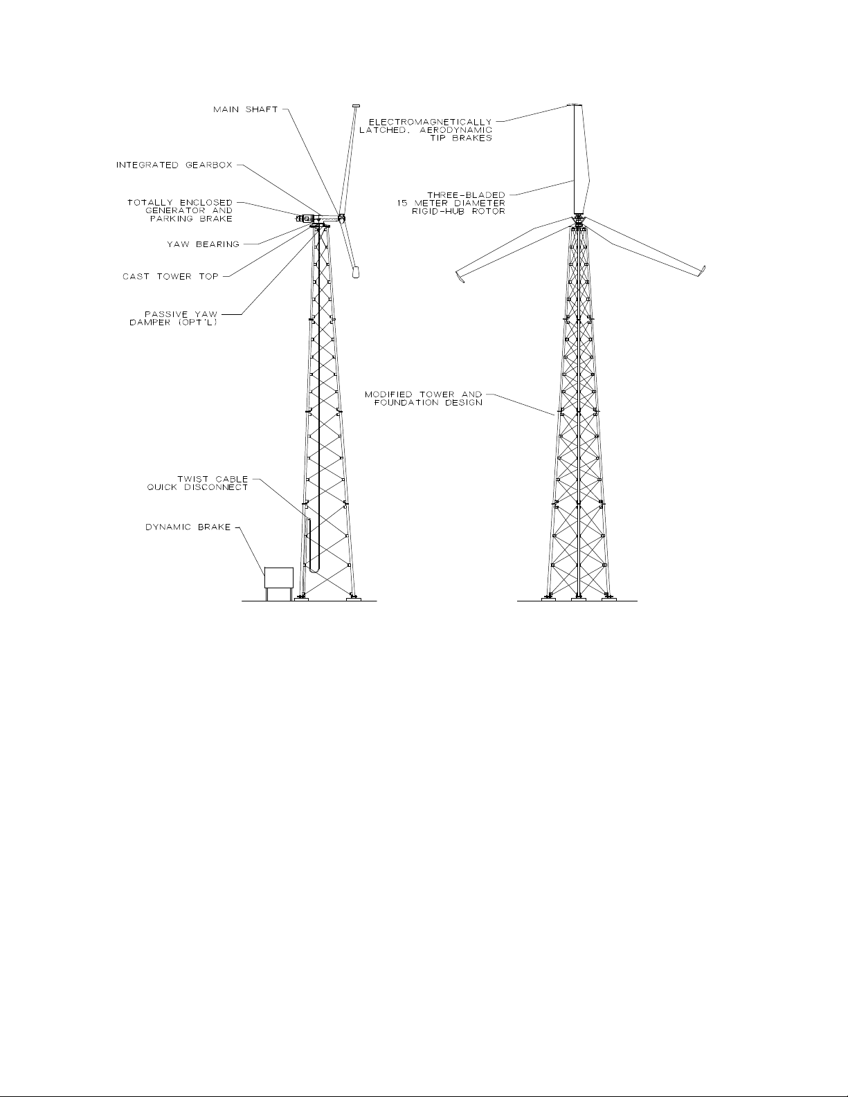
2.1 General Description and Features of the Turbine
The designation 15/50 refers to the 15 m diameter wood/epoxy or fibreglass rotor and its
projected rated output of 50 kW. This rated output is achieved at 12 m/s (26.8 mph) by the 50 Hz
version and at 11.3 m/s (25.3 mph) by the 60 Hz one.
The AOC 15/50 includes the following design features:
• Advanced NREL thick series airfoils
• High strength to weight ratio wood/epoxy or fiberglass blades
• Electro-magnetically/actively controlled tip brakes
• Single piece hub casting
• Rotary transformer to power the tip brake magnets
• Integrated planetary gearbox
• Induction generator
• Single piece cast tower top with turn table yaw bearing
• Uniformly tapered lattice tower
• Dynamic brake
• PLC based controller with adaptive features
• Optional tilt-up lattice tower
Both turbine versions are designed to cut in at 4.6 m/s (10.2 mph). The 50 Hz version reaches its
peak continuous output of 55 kW at 15 m/s (34 mph); the 60 Hz one achieves its peak of 65 kW
(60 Hz) at 16 m/s (36 mph). Assuming 100% availability and average wind speeds of 8 m/s (18
mph), the 50 Hz wind turbine is calculated to produce approximately 190,000 kWh per year and
the 60 Hz one, 215,000 kWh. In average wind speeds of 6.7 m/s (15 mph), the 50 Hz version
produces approximately 145,000 kWh annually and the 60 Hz one, 153,000 kWh.
NOTE: Energy production is site specific and varies with altitude, temperature,
topography, climate and the wind turbine’s proximity to other structures, as well as its
maintenance condition.
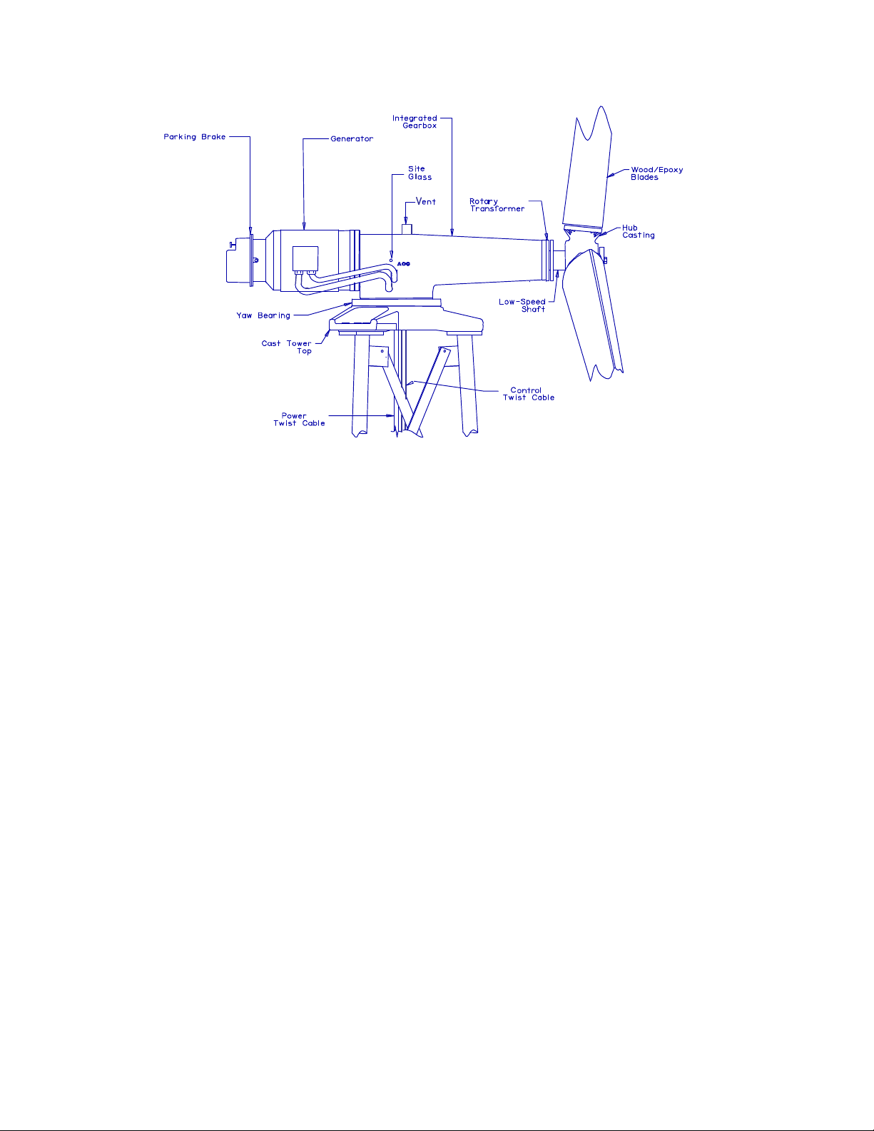
The standard tower is a 24.4 m (80 ft) tall, self-supporting lattice structure. The gearbox is
integrated in the single piece cast housing. See Figure 2-2 for a more detailed view of the drive
train assembly. The generator is flange mounted to the planetary gearbox, with the parking
brake coupled directly to the generator.
NOTICE: Use of the material contained in this document is subject to the warning on page Iv and the disclaimer
on page v of this document.
DOC012R02 AOC 15/50 User Manual Nov 2001
Page 17
2.0 System Description
9
Figure 2-1 AOC 15/50 Wind turbine
NOTICE: Use of the material contained in this document is subject to the warning on page Iv and the disclaimer
on page v of this document.
DOC012R02 AOC 15/50 User Manual Nov 2001
Page 18
2.0 System Description
Figure 2-2 AOC 15/50 Wind turbine assembly, drive train detail
10
Figure 2-3 AOC 15/50 Drive train assembly
NOTICE: Use of the material contained in this document is subject to the warning on page Iv and the disclaimer
on page v of this document.
DOC012R02 AOC 15/50 User Manual Nov 2001
Page 19

2.0 System Description
2.2 Control System Description
The following parameters are monitored by the wind turbine’s control system. It initiates
shutdowns when faults have been detected to protect the wind turbine from mechanical and
electrical damage.
UTILITY NETWORK:
• Over/under voltage
• Phase loss
• Phase reversal
• Over/under frequency (optional)
TURBINE:
• Generator temperature
• Rotor speed
• Power (derived from rotor speed)
• Parking brake current
SYSTEM:
• Wind speed (redundant anemometers)
• Ambient temperature switch (optional)
11
2.3 Operation Description
The AOC 15/50 is a downwind turbine, i.e. its blades rotate downwind of the drive train
assembly. Furthermore, it has no active yaw control and depends on its blades to track the wind.
In winds outside of the required wind band, the PLC (Programmable Logic Controller)
disconnects the wind turbine from the grid and parks it; the wind turbine is brought to a complete
stop. The parking brake remains applied, thereby preventing the blades from rotating. However,
they will still track the wind and the wind turbine will pivot about its yaw bearing accordingly.
The AOC 15/50 has three main modes of operation: test, off and on. The setting of the
TEST/OFF/ON switch determines the parameters monitored by the PLC and which other
switches can be activated. When the turbine TEST/OFF/ON switch is set to OFF, the PLC only
monitors grid faults.
Once the turbine TEST/OFF/ON switch is set to ON, the PLC starts evaluating the wind speed
data which, together with the generator rotor speed, is the most important source of input data to
the PLC; grid related parameters and thermal relays play a secondary role.
The wind speed is measured using two cup anemometers. For the wind turbine operation the
wind speed has to fall within the specified speed band of 3.6-22.3 m/s (8-50 mph). The cut-in
speed of 4.9 m/s (11 mph) is slightly higher than its minimum operational speed because of the
NOTICE: Use of the material contained in this document is subject to the warning on page Iv and the disclaimer
on page v of this document.
DOC012R02 AOC 15/50 User Manual Nov 2001
Page 20

2.0 System Description
12
inertia of the rotor and drive train that must be overcome initially. Once the wind speed
conditions are met, the parking brake is released and the generator starts rotating, at which point
PLC starts monitoring the generator rotor speed.
Once the parking brake has released and the rotor speed is in band,the wind turbine is connected
to the grid automatically. The wind turbine will then stay on-line until wind conditions fall
outside the operating band or until a fault or shutdown is registered. The generator shaft speed is
measured using two speed sensors from which the PLC can tell whether the shaft speed falls
within the required range. Since power produced is proportional to rotor speed, the rotor speed is
also used to check for excessive power generation.
Whenever the wind and/or shaft speeds deviate from the specified values the PLC initiates a
shutdown of the wind turbine system. In order to avoid unnecessary shutdowns, each fault is
monitored for a set period to confirm that it is not due to a temporary deviation but to a definite
change in the operating conditions. Since faults impact on the system with varying degrees of
severity, in terms of possible electrical or mechanical damage, the time delays after which a
shutdown is initiated differ.
Should the PLC register a fault that requires the wind turbine to be shut down, it does so in a set
sequence. The tip brakes and dynamic brake are deployed immediately. The parking brake is
then deployed after a variable time delay, generally set to 4 seconds. Following any deployment
of the brakes the wind turbine enters a cooling cycle, generally set to 15mins. The turbine will
not be available to comeback on line until the end of the cooling cycle to prevent overheating of
the brake components.
The dynamic and parking brakes can be tested individually when their test switches are set to ON
and the TEST/OFF/ON switch is set to TEST. See section 9.1 for a more detailed description of
the individual switches.
NOTICE: Use of the material contained in this document is subject to the warning on page Iv and the disclaimer
on page v of this document.
DOC012R02 AOC 15/50 User Manual Nov 2001
Page 21

Photo Courtesy of
13
3.0 Safety Guidelines
NOTICE: Use of the material contained in this document is subject to the warning on page Iv and the disclaimer
DOC012R02 AOC 15/50 User Manual Nov 2001
BED
TOWER ERECTION AT BURLINGTON ELECTRIC DEPARTMENT
on page v of this document.
Page 22

3.0 Safety Guidelines
14
This section covers the safety information needed by a technician to install, operate and
maintain the AOC 15/50 safely. Special safety considerations for specific circumstances are
highlighted throughout this manual.
CAUTION
THE RESPONSIBILITY FOR SAFE CONDUCT AND
OPERATION ULTIMATELY RESTS WITH THE OPERATOR/
TECHNICIAN.
3.1 Personnel Training
It is essential that installation, operation and maintenance personnel be instructed in the safe
operation procedures outlined in this section. Standard safety procedures should be established
and a program of regular safety training should be carried out to ensure consistent information,
regularized safety habits and efficient communication while working at the wind turbine site(s).
3.2 Safety Equipment
AOC recommends the use of approved safety equipment for any work carried out within 30.5 m
(100 ft) of an AOC 15/50.
For climbing and positioning on the erected wind turbine, an ANSI approved full body harness
should be used. AOC also recommends using a Rohn-Loc Climbing System. Positioning
lanyards are usually necessary for turbine installation and maintenance and should be ANSI
approved. AOC recommends the use of fall arresting lanyards in conjunction with positioning
lanyards, as the latter are not designed for fall protection. The fall arresting lanyards should be
no longer than 1.8 m (6 ft) and incorporate deceleration devices. All connections and anchor
points should be capable of supporting 2,270 kg (5,000 lbs.). Self-locking snap hooks and selflocking carabiners are required.
Equipment should be visually inspected for excessive wear and abrasion before each use. All
damaged or questionable equipment should be discarded immediately. Any equipment, which
has been subject to a fall, should be removed from service and discarded.
When working on electrical equipment and/or wiring, technicians must wear protective gloves
rated for the voltage level involved or be certain that the system is not, and will not, be
energized by employing a visual open/lockout process. Whenever any hazard exists,
appropriate safety glasses/shields must be worn.
NOTICE: Use of the material contained in this document is subject to the warning on page Iv and the disclaimer
on page v of this document.
DOC012R02 AOC 15/50 User Manual Nov 2001
Page 23

3.0 Safety Guidelines
15
3.3 Start-up and Shut-down Safety Procedures
Prior to starting up a wind turbine, the operator should warn any personnel in the area that it will
be started and to visually inspect the area to ensure that they are clear of it. In addition, the
operator should ensure that there are no visual signs indicating problems with the wind turbine.
During a shutdown sequence, no personnel should approach the wind turbine, until it has come
to a complete stop.
3.4 Securing Machine for Maintenance and Repair
The wind turbine should be switched off and the yaw lock engaged before any maintenance is
performed. The parking brake automatically engages whenever the wind turbine is shut down,
preventing the rotor from turning. The yaw lock must be engaged manually and once engaged
prevents the wind turbine from yawing, providing a safe working environment. To engage it,
trained personnel must climb the tower to immediately below the tower top. The yaw lock bolt
must be screwed clockwise until its top endplate engages the yaw bearing between two of the
yaw bearing’s interfacing bolts.
Figure 3-1 Yaw lock
If personnel safety or environmental conditions warrant securing the rotor or if the work carried
out requires the parking brake to be released to change the rotor position, it is recommended that
one blade be strapped to the tower or to the gearbox housing to prevent unintended rotor motion.
NOTICE: Use of the material contained in this document is subject to the warning on page Iv and the disclaimer
on page v of this document.
DOC012R02 AOC 15/50 User Manual Nov 2001
Page 24

3.0 Safety Guidelines
16
Ropes may replace straps provided care is taken not to damage the blade surface; cables or
chains should not be used.
CAUTION
NEVER USE METAL CHAINS OR CABLES TO SECURE THE
BLADE, SINCE DAMAGE TO THE BLADE IS LIKELY.
3.5 Climbing Safety
For all activities where persons could be subject to a fall of 1.8 m (6 ft) or more, appropriate fall
protection equipment should be used, which should be fastened to a secure anchor point,
preferably above the climber. Only the tower leg fitted with climbing pegs should be used for
ascending and descending the tower. Once the technician has reached the top, he/she should
attach himself to a secure anchor point. The drive train has four hoist rings that can be used as
anchor points. See Figure 3-2. Holes in the tower brace clips also provide secure anchor points.
Figure 3-2 Secure anchor points for service work
Only trained and qualified technicians should attempt to climb a wind turbine tower and should
use OSHA/ANSI approved practice and equipment. All climbers should be trained in the proper
use of fall protection equipment. AOC strongly discourages climbing when the wind turbine is
operating or when wind speeds exceed 11 m/s (25 mph).
Whenever climbing a tower or performing a service function above ground level AOC
recommends at least two service personnel working together. Wireless communication devices
(preferably hands-free) are recommended to facilitate communication between tower and
NOTICE: Use of the material contained in this document is subject to the warning on page Iv and the disclaimer
on page v of this document.
DOC012R02 AOC 15/50 User Manual Nov 2001
Page 25

3.0 Safety Guidelines
17
ground personnel. The area around the tower should also be roped off with appropriate warning
signs indicating falling objects.
Finger rings should not be worn while climbing structures or vehicles, or while performing any
task where the ring might be caught under or snagged by a projecting or moving item.
3.6 Electrical Safety
WARNING
WHENEVER POSSIBLE, ELECTRICAL EQUIPMENT SHOULD
BE DE-ENERGIZED AND GROUNDED PRIOR TO SERVICING.
CAUTION MUST BE TAKEN TO ENSURE THAT THE DYNAMIC
BRAKE AND THE POWER FACTOR CORRECTION
CAPACITORS ARE DISCHARGED BEFORE SERVICING.
Electrical equipment should not be serviced while standing in water, on wet surfaces or during
significant precipitation. Hands must be dry. Any electrical power supply to tools and
conveniences should be grounded.
A shirt or jacket with full-length sleeves rolled down and buttoned up, as well as an electrical
safety hat should be worn when working on or near live parts.
Loose, dangling metal chains, key chains, or conductive jewelry of any kind should not be worn
while working on or near energized parts. Each employee should wear gloves suitable for the
work. Rubber glove protectors should not be used as work gloves. Wristwatches with metal
cases and watchbands should not be worn while working on or near energized equipment.
3.7 Weather Related Safety
It is important to observe weather conditions and to take appropriate action when a weather
related safety hazard arises. No service work should be performed in the presence or threat of
lightning. Wet and/or ice laden towers should not be climbed, nor should electrical equipment
be worked on during significant precipitation. Towers should not be climbed when average
wind speeds approach 11 m/s (25 mph) or wind gusts exceed 13 m/s (29 mph).
NOTICE: Use of the material contained in this document is subject to the warning on page Iv and the disclaimer
on page v of this document.
DOC012R02 AOC 15/50 User Manual Nov 2001
Page 26

3.0 Safety Guidelines
18
WARNING
NO SERVICE WORK SHOULD BE PERFORMED ON A WIND
TURBINE IN THE PRESENCE OR THREAT OF LIGHTING. WET
AND/OR ICE LADEN TOWERS SHOULD NOT BE CLIMBED.
EXTERIOR ELECTRICAL EQUIPMENT SHOULD NOT BE
WORKED ON DURING SIGNIFICANT PRECIPITATION.
3.8 Emergency Procedure
CAUTION
WHEN A HAZARD EXISTS, PERSONNEL SAFETY MUST BE
ENSURED BEFORE ADDRESSING THE SAFETY OF THE
WIND TURBINE EQUIPMENT. IN ALL CASES, SAFE
EFFORTS SHOULD BE MADE TO BRING THE WIND
TURBINE TO A FULL STOP OR TO PREVENT OVER
SPEEDING.
AOC takes extreme care to design a safe and reliable product and the AOC 15/50 has been
designed to meet strict and extensive safety guidelines. However, due to the variety of
unpredictable and possibly extreme conditions it may experience, operators should prepare and
have on hand site-specific emergency procedures to effectively address the following hazards:
• Turbine over-speed
• Loose fasteners
• Structural damage
• Earthquakes
• Sand storms
• High vibration
• Complete braking failure
• Electric fires
• Lighting
• Hurricanes
• Blade damage/separation
• Tower damage
• Cable over-wrap and/or separation
AOC recommends the following as a generic safety plan in the unlikely case of an emergency:
1. Do not approach the AOC 15/50 or any of its components if one of the safety hazards
mentioned above is suspected. Always maintain a safe distance (at least 90 m, 300 ft)
upwind of the wind turbine.
2. If the controller area is deemed safe, depress the emergency stop button. The wind
turbine should come to a complete stop and the main contactor should de-energize.
3. Contact the local emergency officials if necessary (i.e. fire marshal, 911, utility, etc.).
4. Contact the wind turbine owner.
5. Do not attempt to operate the AOC 15/50 without first contacting AOC. It may be
necessary to schedule an inspection by AOC personnel.
NOTICE: Use of the material contained in this document is subject to the warning on page Iv and the disclaimer
on page v of this document.
DOC012R02 AOC 15/50 User Manual Nov 2001
Page 27

3.0 Safety Guidelines
DO NOT ATTEMPT TO OPERATE THE AOC 15/50 WITHOUT AOC
CONSULTATION AFTER A SERIOUS EVENT HAS OCCURRED.
AOC RECOMMENDS A COMPLETE INSPECTION OF THE
TURBINE AND ITS COMPONENTS BY TRAINED PERSONNEL
AFTER ANY SUCH EVENT. FAILURE TO DO SO MAY RESULT IN
POOR PERFORMANCE, INJURY OR DEATH.
19
WARNING
NOTICE: Use of the material contained in this document is subject to the warning on page Iv and the disclaimer
on page v of this document.
DOC012R02 AOC 15/50 User Manual Nov 2001
Page 28

3.0 Safety Guidelines
20
NOTICE: Use of the material contained in this document is subject to the warning on page Iv and the disclaimer
on page v of this document.
DOC012R02 AOC 15/50 User Manual Nov 2001
Page 29

Part II
21
Part II
NOTICE: Use of the material contained in this document is subject to the warning on page Iv and the disclaimer
on page v of this document.
DOC012R02 AOC 15/50 User Manual Nov 2001
Page 30

Part II
22
NOTICE: Use of the material contained in this document is subject to the warning on page Iv and the disclaimer
on page v of this document.
DOC012R02 AOC 15/50 User Manual Nov 2001
Page 31

Photo Courtesy of
23
4.0 Planning and Installation Checklist
NOTICE: Use of the material contained in this document is subject to the warning on page Iv and the disclaimer
DOC012R02 AOC 15/50 User Manual Nov 2001
KEA
SITE CONSTRUCTION AT KOTZEBUE ELECTRIC ASSOCIATION
on page v of this document.
Page 32

4.0 Planning and Installation Checklist
24
The following sections are intended to assist customers in addressing the relevant installation
details in a logical sequence. Although most points apply to both large and small projects, not
all will apply to every project. To ensure thorough planning, it is strongly recommended that
customers understand why a particular detail is or is not appropriate to their installation.
By reviewing the entire list repeatedly throughout the project, the customer should be able to
ensure that none of the details, necessary to complete it, have been overlooked.
4.1 Siting Factors
Site selection has a significant effect on annual energy production. It is, therefore, worth the
additional time and effort to locate the most suitable site to ensure optimal energy production
and maximize the wind turbine’s lifespan. When selecting a site, the following factors should
be considered:
• Wind resource characteristics
§ Average wind speed
§ Makeup of wind speed average (frequency and duration of power producing winds)
§ Prevailing wind direction(s)
§ Turbulence
§ Peak wind speeds
• Height and location of obstructions
• Distance from utility service point
• Local restrictions relative to height, proximity to boundaries, etc.
• Tower height
• Proximity to other wind turbines
• Site accessibility and its effect on construction and maintenance costs
• Safety zone preventing public access
4.2 Utility Factors
The AOC 15/50 includes an induction generator, which depends on the interfacing electrical
system for excitation. Each wind turbine has a fixed set of power factor correction capacitors
installed in the dynamic brake capacitor box. To ensure a safe and efficient installation, the
following utility related factors should be considered:
• Buy back rates, contract options, green pricing and net billing
• Available line capacity (in kVA)
• Available fault current
• Voltage and phase configuration of the primary circuit and the local utility line
• Distance to nearest substation
• Size and winding configuration of the step down transformer required at the site (in
kVA)
NOTICE: Use of the material contained in this document is subject to the warning on page Iv and the disclaimer
on page v of this document.
DOC012R02 AOC 15/50 User Manual Nov 2001
Page 33

4.0 Planning and Installation Checklist
25
• Line protection required
• Cogeneration standards for small power producers
• Interconnection hardware and wiring standards
• System operation requirements:
§ Voltage regulation
§ Power factor
§ Protective devices
§ Utility/wind turbine interface responsibilities
To interface with the utility network correctly all power factor correction capacitors or
unique loads connected to the utility system need to be identified by the customer.
Furthermore, the Required Customer Power Grid Information sheet should be completed to
assist AOC in designing the most suitable interface. See Appendix K.
4.3 Permits and Approvals
Local authorities often require a wind turbine operator to obtain permits or approvals, some of
which have been identified below. It is important to determine which of these apply to a site
and whether any independent inspections are required.
Issuing Authority:
• Municipality or local council
• Country
• State or Province
• Federal (FAA, FCC, etc.)
• Commission (energy, conservation, historic, etc.)
• Utility
Type:
• Construction
• Foundation engineering
• Electrical works
• Interconnection
• Zoning
• Communication interference
• Aviation interference
• Environmental impact
4.4 Plans and Drawings
NOTICE: Use of the material contained in this document is subject to the warning on page Iv and the disclaimer
on page v of this document.
DOC012R02 AOC 15/50 User Manual Nov 2001
Page 34

4.0 Planning and Installation Checklist
26
The following list contains suggested documentation to prepare in advance and have on hand to
ensure efficient and proper site development, as well as for submittal for the necessary
approvals:
• Plot plan
• Site layout
• Tower foundation drawing
• Tower assembly drawing
• Site wiring layout
• Control house interior wiring (if applicable) diagram
• Control house physical layout (if applicable)
• Utility interface - single line drawing
• Utility interface - three line drawing
• Wind turbine generator to control box wiring schematic
• Wind turbine generator wiring diagram
4.5 Construction Planning Considerations
To reduce delays later and to minimize cost, the following items should be considered during
the planning process:
• Subcontractor roles and responsibilities
• Cable trenches (type, length and depth)
• Control enclosure design
• Site specific weather extremes
• Tower foundation type
• Foundation forming details
• Site accessibility and road conditions
• Crane availability and cost
• Concrete availability and cost
• Backhoe availability and cost
• Concrete reinforcing bar availability and cost
• Labor skills and related costs
• Soil characteristics
§ Soil stability
§ Depth to water table
§ Depth to significant frost
§ Allowable bearing capacities
• Blasting needs
• Tripod or backhoe for tower assembly
• Availability of hand tools
• Concrete working tools
• Anchor bolt template and verification of proper placement
• Fencing materials and security
NOTICE: Use of the material contained in this document is subject to the warning on page Iv and the disclaimer
on page v of this document.
DOC012R02 AOC 15/50 User Manual Nov 2001
Page 35

4.0 Planning and Installation Checklist
27
4.6 Electrical Planning Considerations
The local wiring inspector should review the design of the electrical installation before work
starts at the site. The following items should be considered in the design/installation of the
electrical system:
• Wire sizes, length and type as described in Appendix M
• Conduit type and size
• Service entrance hardware
• Revenue meter specifications
• Protective hardware required by the interfacing utility
• Distribution panel(s) with properly sized circuit protection
• Single phase power for control house lights and receptacles
• Step down transformer characteristics
• Control house interior wire ways
• Control house junction box(es)
• Multiple unit control for wind power stations
• Twist cable termination box
• Foundation/conduit interfaces
4.7 Installation Tools and Equipment
The installation of the AOC 15/50 requires specific tools and equipment (see Appendix I).
Below is a breakdown of steps to take or equipment to have on hand for the three main
installation phases.
For tower assembly:
• Tower manufacturer’s assembly drawings
• Checklist of tower parts, hardware and tools
• Torque specifications
• Tripod, bucket, backhoe or boom truck
• Personnel for lifting and assembly
• Anemometer boom and brackets
To prepare machine:
• If wind turbine generator was shipped in a crate, remove from crate
• Check components
• Open blade crate
For installation:
• Slings, ropes, buckets and tools
• Adequately trained personnel
NOTICE: Use of the material contained in this document is subject to the warning on page Iv and the disclaimer
on page v of this document.
DOC012R02 AOC 15/50 User Manual Nov 2001
Page 36

4.0 Planning and Installation Checklist
28
• Platform or bucket for blade installation
• Appropriate safety equipment
• Crane
• Forklift or boom truck
4.8 Installation Personnel Considerations
The installation and maintenance of a wind turbine requires specialized skills, equipment and
experience. AOC assumes that all installation and operation personnel will have these skills,
experience and equipment. Only trained and qualified technicians should attempt to climb a
wind turbine tower and should use OSHA/ANSI approved practice and equipment. It is highly
recommended that a trained AOC representative be present for the erection and assembly of the
wind turbine (see Section 4.9). The following personnel should also be present, as and when
required, during installation:
• One to two qualified technicians trained in climbing safety to erect and install wind
turbine
• Qualified crane operator to operate the crane during tower and wind turbine lifting
• Certified electrician and/or utility personnel to install cables and wire controllers
• Additional labor for non-technical tasks such as tower assembly
4.9 General Installation/Commissioning Timeline
The following timeline represents the minimum installation schedule for one wind turbine under
ideal circumstances. Three to five days is usually a reasonable estimate. Poor weather
conditions, logistic problems and poor planning may extend the timeline considerably.
Site Preparations and Construction:
• Pour foundation
• Create cableways, wiring, power cables
• Install and wire control boxes, capacitor, and dynamic brakes
• Inspect wind turbine and hardware
NOTICE: Use of the material contained in this document is subject to the warning on page Iv and the disclaimer
on page v of this document.
DOC012R02 AOC 15/50 User Manual Nov 2001
Page 37

4.0 Planning and Installation Checklist
Day 1:
• Plan and prepare erection
• Assemble tower
• Test generator and use it as a motor to test drive train
• Clean blades and install tip brake cable
• Prepare tip brake studs and cavity
• Prepare blade bolt inserts
• Attach twist cable
• Install two of three blades if time permits (fork lift, boom truck, etc.)
Day 2:
• Lift and install tower on foundation (crane)
• Install blades on hub
• Install tip brakes on blade ends
• Lift and mount machine onto the tower
• Torque tower top fasteners
• Torque all tower bolts and add pal nuts
Day 3:
• Install and wire anemometers
• Wire twist cable junction box and disconnect (if applicable) at tower base
• Grout tower legs
• Mount warning signs as required
• Troubleshoot and commission
Day 4:
• Complete any further installation details
• Carry out final QA check
• Monitor performance (wind permitting)
29
NOTICE: Use of the material contained in this document is subject to the warning on page Iv and the disclaimer
on page v of this document.
DOC012R02 AOC 15/50 User Manual Nov 2001
Page 38

4.0 Planning and Installation Checklist
30
NOTICE: Use of the material contained in this document is subject to the warning on page Iv and the disclaimer
on page v of this document.
DOC012R02 AOC 15/50 User Manual Nov 2001
Page 39

of
31
5.0 Site Preparation
Photo Courtesy
BED
FOUNDATION CONSTRUCTION AT THE BURLINGTON ELECTRIC DEPARTMENT PROJECT
NOTICE: Use of the material contained in this document is subject to the warning on page Iv and the disclaimer
on page v of this document.
DOC012R02 AOC 15/50 User Manual Nov 2001
Page 40

5.0 Site Preparation
32
WARNING
DURING THE INSTALLATION OF A WIND TURBINE, THE SITE
SHOULD BE MAINTAINED SO THAT IT DOES NOT PRESENT A
SAFETY RISK/HAZARD TO PERSONNEL.
The following sections discuss some of the siting factors, which must be considered before the
wind turbine arrives.
5.1 Site Access
Access to the site is a prime consideration when installing a wind turbine. Limitations in site
access will determine the type of installation and equipment that can be used. Potentially
limiting factors include:
• Roadways (existence, permits, size, surface, restricted use, weight bearings)
• Bridges (size, load capacity, width and height clearances)
• Physical clearances (overhead wires, lamp posts, turning radii, grade)
• Traffic (movement to and at the site)
• Lay down area (space to assemble the tower and locate components prior to installation)
5.2 Foundation Installation
Foundation types and installation approaches are site specific and the foundations must be
designed for the load conditions expected at the site in question. Refer to IEC Standards for
Wind Turbines for additional information. Since AOC offers a standard and tilt-up tower, it
should be noted that the chosen configuration will affect the position of the anchor bolts. For
planning purposes regarding the tilt-up towers, it should be remembered that AOC only supplies
the hinges not the erection equipment.
See Appendix F for foundation loads and details. The civil engineer responsible for the
foundation design should consider site specific conditions.
Each tower leg should be grounded as per EIA standards. Rohn recommends using three 5/8”
galvanized ground rods, 8 feet long and mechanically connected to each leg using #4 gage wire.
NOTICE: Use of the material contained in this document is subject to the warning on page Iv and the disclaimer
on page v of this document.
DOC012R02 AOC 15/50 User Manual Nov 2001
Page 41

5.0 Site Preparation
It may be advisable to excavate trenches for power and control cables at the time of digging the
foundations. For wire and cable information, refer to Appendix M.
CAUTION
CAREFUL MEASUREMENT AND USE OF AN
ACCURATE ANCHOR BOLT TEMPLATE BEFORE,
DURING AND AFTER CONCRETE POURING CAN
MINIMIZE ALIGNMENT PROBLEMS OR
FOUNDATION REPAIRS.
5.3 Receiving the Wind Turbine at the Site
Wind turbines are often installed on uneven terrain. Moving components and assembling them
is easier on level ground. It is, therefore, suggested that a level lay-down area is either
excavated (taking care to prevent erosion) or built, on which the wind turbine can be assembled
and erected. Items such as blades may need to be anchored and covered if the site experiences
strong winds or other hazardous environmental conditions.
The wind turbine will normally be shipped in four crates. Their nominal weights and sizes are
listed in Appendix E. For containerized shipping please note that both the tower sections and
the blades are too long to fit a 20 ft container.
Once the shipment has been offloaded from the truck:
• The packing list should be checked to confirm that all items have been received. The
items should be inspected for damage and if any damage is suspected the shipping
company should be contacted regarding claims procedures. AOC should also be
notified of the parts needed. Particular care should be taken to inspect the twist cable
and the blade surfaces.
• Any scratches obtained during transit should be touched up. CRC Industrial SP
Corrosion Inhibitor or an equivalent can be used as an anticorrosive on any bare metal
surface. Failure to properly coat bare metal may result in significant corrosion.
• With the wind turbine on level ground, the oil level in the gearbox sight glass should be
checked. See Figure 2-2 for the sight glass location. It should be half way up the sight
glass.
• All grease fittings should be intact. These are located on the generator housing, yaw
bearing, yaw lock.
The checklist is provided in Appendix G.
33
NOTICE: Use of the material contained in this document is subject to the warning on page Iv and the disclaimer
on page v of this document.
DOC012R02 AOC 15/50 User Manual Nov 2001
Page 42

5.0 Site Preparation
34
NOTICE: Use of the material contained in this document is subject to the warning on page Iv and the disclaimer
on page v of this document.
DOC012R02 AOC 15/50 User Manual Nov 2001
Page 43

Photo Courtesy of
35
6.0 Tower and Wind Turbine Generator Installation
NOTICE: Use of the material contained in this document is subject to the warning on page Iv and the disclaimer
DOC012R02 AOC 15/50 User Manual Nov 2001
BED
TOWER ASSEMBLY AT THE BURLINGTON ELECTRIC DEPARTMENT PROJECT
on page v of this document.
Page 44

6.0 Tower and Wind Turbine Generator Installation
36
The following sections describe the assembly of the tower, as well as its erection and the
installation of the wind turbine generator.
6.1 Tower Assembly
For the assembly details refer to the manufacturer’s instruction packet shipped with the tower.
The tower assembly drawings for the standard 24.4 m (80 ft) tower are supplied in Appendix C;
for those of the 30.5 m (100 ft) tower see Appendix D.
The tower will generally be assembled horizontally with two of its three legs near the ground.
Blocks should be used to support these two legs at several locations along their length. The
height of the blocks should be chosen to ensure that the tower is straight and to allow crossbraces to be bolted to the legs. The blocks must have sufficient strength and stability for the
tower to be worked on safely.
After laying out the tower leg sections, the braces should be matched to their respective brace
clips on the legs. Braces and legs are clearly stamped with their part numbers and are referenced
in the tower drawings (see Appendix C or D). The bottom leg flanges of the bottom tower
section and the upper leg flanges of the topmost tower section are angled. This ensures that they
are parallel to the foundation and the turbine tower top casting once the tower is vertical.
The cross-braces between two legs from each section should be installed. The third leg then has
to be lifted above the two lower legs for the remaining cross-braces to be installed. The leg can
be raised using a bucket loader, fork lift or similar aid.
The open angle on the cross-braces should face towards the tower base, to shed any water. The
longer distance between the middle and the outer bolt hole in the cross-brace should also be
positioned facing down, towards the base. This configuration should be repeated down the tower
and around its sides. The top braces of each section start in the top hole of the brace clips, and
the bottom braces of each section terminate at the bottom hole of the brace clips. The crossbrace holes may not line up with the brace clip hole easily but they can be aligned using a pair of
drift pins and two vise grips to hold the brace in place while a bolt is inserted.
Brace bolts should be installed with the head on the inside of the tower and the nut on the
outside. Flange bolts should be inserted from the bottom up, with the nut on the flange top. The
flange bolts on the top and bottom most sections should be left slightly loose until the tower is in
place, as should the cross-brace bolts on these sections. It is helpful to use templates on the top
and bottom sections when assembling the tower. This ensures a better fit when the tower is
erected on the foundation. The bolts on the middle sections may be tightened to their required
torques after the tower has been completely assembled.
The 1” flange bolt nuts should be torqued to 340 Nm (250 ft-lbs) and the 5/8” nuts on the braces,
to 200 Nm (150 ft-lbs). Pal nuts should be placed snug tight on every bolt after the nut has been
torqued, thereby indicating that the bolt has been torqued to specification.
NOTICE: Use of the material contained in this document is subject to the warning on page Iv and the disclaimer
on page v of this document.
DOC012R02 AOC 15/50 User Manual Nov 2001
Page 45

6.0 Tower and Wind Turbine Generator Installation
37
NOTE: A template identical to the anchor bolt template can be bolted to the bottom leg
flanges during tower assembly to insure a proper fit during the tower erection. Using both
templates should theoretically allow all bolts to be torqued before erection.
6.2 Tower Erection
Appendix G contains the Installation QA checklist that should be used during the installation
process.
Much time can be saved if a crane capable of lifting the tower as one complete unit is used.
When considering crane capacity, the erection load and local wind conditions should be taken
into account. The centerline of the drive train is approximately 1.2 m (4 ft) above the chosen
tower height. The 24.4 m (80 ft) tower weighs approximately 3,180 kg (7,000 lbs) and the 30.5
m (100 ft) tower, approximately 4,550 kg (10,000 lbs). The wind turbine generator weighs
approximately 2,480 kg (5,450 lbs). See Appendix E. The length of the crane ball, lifting sling
and the height lost due to boom angle reach should also be taken into account.
Before the tower is set on the foundation, an anchor nut should be placed on each anchor bolt to
serve as a base for the tower flanges to rest upon. These nuts should be leveled before the tower
is placed on them, using a survey transit and straight rod or a long straightedge with a bubble
level, for example. Tolerance is not important initially, as the nuts may need to be adjusted in
order to level the gearbox.
The tower can be lifted using three appropriately rated, separate slings or cables of equal length,
each of which is hooked to the crane ball at one end and to the tower, near the top of its top
section legs, at the other. The lifting devices should be inspected for correct attachment
before raising the tower. Special care should be taken not to damage the lifting webbing on
sharp edges. The tower should be lifted slowly and set on the anchor bolts carefully. The tower
base flanges may not fit the anchor bolts precisely, especially if a base template was not used.
WARNING
DO NOT HAMMER OR BEND ANCHOR BOLTS TO FIT THE
TOWER BASE. THIS MAY CAUSE CATASTROPHIC
STRUCTURAL FAILURE AND RESULT IN SEVERE INJURY OR
DEATH.
The tower legs may have to be twisted along their axes, to obtain the correct alignment between
the flange holes and the anchor bolts. This can be done using a come-along and pry-bar. As the
tower is lowered onto the base nuts, the top locking nuts should be placed on the anchor bolts as
soon as the first threads protrude from the flanges. The nuts should be tightened incrementally
as the tower is lowered. Once the tower is in place, the lock nuts should be tightened hand snug,
NOTICE: Use of the material contained in this document is subject to the warning on page Iv and the disclaimer
on page v of this document.
DOC012R02 AOC 15/50 User Manual Nov 2001
Page 46

6.0 Tower and Wind Turbine Generator Installation
38
after which the tension on the crane cable can be relaxed. A technician should verify that the
tower top is level by climbing the tower. Any adjustments required to level the tower top should
be made by adjusting the anchor nuts.
The 1½ “ anchor bolt nuts should be torqued to AISC snug tight standards after the tower has
been erected; snug tight being defined as the tightness needed to bring all plies in a joint into
firm contact. This may be obtained by a few impacts of an impact wrench or the full effort of a
man using an ordinary spud wrench. Following this, the tower grounding rods should be
connected (see Section 5.2) and the slings released.
WARNING
ONLY TRAINED AND QUALIFIED TECHNICIANS SHOULD
ATTEMPT TO CLIMB A WIND TURBINE TOWER AND SHOULD
USE OSHA/ANSI APPROVED PRACTICE AND EQUIPMENT. ANY
ACTIVITIES WHERE PERSONS COULD BE SUBJECT TO A FALL
OF SIX FEET OR MORE SHOULD BE PERFORMED USING
APPROPRIATE FALL PROTECTION EQUIPMENT FASTENED
TO A SECURE ANCHOR POINT. SEE APPENDIX S FOR A
DESCRIPTION OF SAFETY EQUIPMENT AND SECURE ANCHOR
POINTS.
A DESIGNATED PERSON SHOULD BE CLEARLY IDENTIFIED
AS THE LIFT COORDINATOR. THE LIFT COORDINATOR
SHOULD DIRECT ALL EQUIPMENT AND PERSONNEL DURING
THE LIFT. HAND SIGNALS (APPENDIX R) MUST BE
CAREFULLY COORDINATED WITH THE CRANE OPERATOR IN
ADVANCE. SUPPLEMENTARY RADIO CONTACT IS STRONGLY
RECOMMENDED.
6.3 Wind Turbine Component Preparation
6.3.1 Tip Brake Installation
After removing the top of the blade crate, the blade tips should be slid on to the edge of the crate
end. The blades should then be pulled out of their crate completely, inspected for damage and
laid on support blocks. The foam packing inserts can be used to separate and support the blades.
Both conduit ends should be free of debris and epoxy!
NOTICE: Use of the material contained in this document is subject to the warning on page Iv and the disclaimer
on page v of this document.
DOC012R02 AOC 15/50 User Manual Nov 2001
Page 47

6.0 Tower and Wind Turbine Generator Installation
39
CAUTION
THE BLADES SHOULD NOT BE SCRATCHED OR GOUGED
DURING SITE HANDLING AS THIS CAN CAUSE A LOSS OF
ROTOR PERFORMANCE AND/OR BLADE DEGRADATION
FROM ENVIRONMENTAL EFFECTS.
The string in the conduit should be used to pull a #10 gage wire through the conduit. The blade
cable should then be attached to the wire (with tape, for example) and pulled through the blade
conduit, with the molded 3-pin connector at the root end of the blade. Lubricating the blade
cable facilitates this operation. Female connectors should be crimped to the black and red wires
and a fork-tongue connector to the blue wire. The female connectors should be connected to the
rectifier and the fork-tongue connector to the ground point on the damper bracket (see Figure 6-
2).
To avoid damaging the tip brakes during blade installation, it is preferable to install them once
the blades have been attached to the hub. Till then, the blade ends should be protected with foam
to prevent damage, should they strike the ground or any hard object.
After connecting the electromagnet, the tip brake assembly should be inserted carefully into the
end of the blade without pinching the electromagnet wires. Each tip brake should be bolted to its
blade using low profile nylon-insert lock nuts over the blade end studs. The lock nuts should be
torqued to 14.8 Nm (11 ft-lbs) for the 5/16" studs and 24 Nm (18 ft-lbs) for the 3/8" studs, using
½" and 9/16" socket wrenches, respectively. It is recommended to step torque each nut to
distribute the force over all studs.
CAUTION
FORCING THE TIP BRAKE INTO THE BLADE CAVITY CAN
DAMAGE BOTH THE BLADE AND THE TIP BRAKE. TIP
BRAKES SHOULD SLIDE INTO THE BLADE CAVITY
EASILY.
After the tip brake has been mounted on the blade and wired, the blade should be positioned so
that the tip brake can open and close freely. The tip brake should be opened and let go; it should
close completely.
NOTICE: Use of the material contained in this document is subject to the warning on page Iv and the disclaimer
on page v of this document.
DOC012R02 AOC 15/50 User Manual Nov 2001
Page 48

6.0 Tower and Wind Turbine Generator Installation
Figure 6-1 Parking brake manual release
40
Figure 6-2 Tip brake installation
NOTICE: Use of the material contained in this document is subject to the warning on page Iv and the disclaimer
on page v of this document.
DOC012R02 AOC 15/50 User Manual Nov 2001
Page 49

6.0 Tower and Wind Turbine Generator Installation
41
6.4 Blade Installation
This procedure should be carried out by a minimum of three technicians. Each blade weighs 135
kg (300 lbs) and can be lifted by a crew of three or four or using equipment such as a back hoe or
a boom truck fitted with nylon slings or ropes. Metal slings or chains should never be used to
move a blade.
CAUTION
NICKS OR GOUGES IN THE BLADE SURFACE CAN
AFFECT THE PERFORMANCE AND THE EXPECTED LIFE
OF THE BLADE SIGNIFICANTLY. TAKE EVERY
PRECAUTION TO PROTECT THE BLADE SURFACE
DURING HANDLING AND INSTALLATION.
The first two blades should be installed with the machine still set on the ground. The yaw lock
should be engaged, to restrict the turbine from rotating about the yaw axis. See Figure 6-4 for
the yaw locking position. The parking brake is released by pulling on the manual release, after
which the hub can be rotated so that a blade can be mounted with its tip or tip brake supported
above the ground (see Figure 6-1). The blade should rest on a piece of packing foam to prevent
surface damage. A drift pin or bolt placed in a blade bolt hole on the hub will help align the
blade with the hub.
WARNING
BLADE WASHERS SHOULD LIE FLAT AGAINST THE HUB
COUNTERBORE. FAILURE TO INSTALL WASHERS PROPERLY
CAN RESULT IN LOOSENING AND FAILURE OF FASTENERS.
THIS MAY RESULT IN BLADE DETACHING, SEVERELY
DAMAGING THE MACHINE AND CAUSING SERIOUS INJURY
OR DEATH.
The red protective plugs should be removed from the blade inserts in the root end. The blade
should be slid onto the hub, with the concave (upwind) side of the blade towards the machine.
The tip brake wire, which exits the trailing edge of the blade near the root, must not be damaged.
It is helpful to tape this down to the blade during assembly.
Note: The concave ('bottom' of the airfoil) MUST face the machine. Only the blade bolt
washers supplied with the wind turbine should be used. These washers are oval shaped and
designed for the blade mounting. The washer must be oriented in the correct position for the
required pitch, as the washers are not symmetric. It is extremely important that the
washers are seated entirely in the hub slot counter bores and rest flat on the bottom of
these counter bores. If the washers are even slightly misaligned, the bolts and washers
should be reassembled.
NOTICE: Use of the material contained in this document is subject to the warning on page Iv and the disclaimer
on page v of this document.
DOC012R02 AOC 15/50 User Manual Nov 2001
Page 50

6.0 Tower and Wind Turbine Generator Installation
42
DO NOT SUBSTITUTE BOLTS. Only the AOC supplied Grade 8, fine thread bolts, 5/8" x
3", should be used to secure the blades to the hub. The tip brakes can be unlatched or
removed (if necessary) to prevent damage during the mounting process.
The four corner bolts on the blade should be installed, initially without the washers, to hold the
blade in place. The pitch tool should be inserted first, in slot #1 (see Figure 6.10), and secured
with a bolt inserted snug tight.
Unlock
Lock
Yaw Lock
Bottom View
Figure 6-4 Yaw lock on tower top
NOTICE: Use of the material contained in this document is subject to the warning on page Iv and the disclaimer
on page v of this document.
DOC012R02 AOC 15/50 User Manual Nov 2001
Page 51

6.0 Tower and Wind Turbine Generator Installation
Figure 6-5 Yaw lock
43
Figure 6-6 Tower top casting
NOTICE: Use of the material contained in this document is subject to the warning on page Iv and the disclaimer
on page v of this document.
DOC012R02 AOC 15/50 User Manual Nov 2001
Page 52

6.0 Tower and Wind Turbine Generator Installation
Blade #1
Figure 6-7 Positioning the blade for attachment
44
Turbine on pallet
Ground level
4 Corner Bolts
Figure 6-8 Bolting blade to a hub
The blade pitch can be adjusted to set the peak power production and to accommodate various
wind resources. For pitch setting, consistency between blades and optimum power capture, AOC
recommends that a pitch tool be used which may be purchased from AOC. Currently a standard,
an aggressive and a conservative pitch setting tool are available. (See figure 6-9 for pitch
variance.) Custom pitch tools may also be designed for specific sites.
At this point the remaining six bolts and ten washers should be installed and the pitch tool
removed. Loctite 271 should be applied to each of the bolts strictly following the procedure
outlined in Appendix J-3. All the blade bolts should be torqued in two stages using a 15/16"
socket: first to 180 Nm (130 ft-lbs) and then to 243 Nm (180 ft-lbs). The blade bolts should be
torqued in a star pattern starting with #1 as shown in Figure 6-10. The blade washers MUST be
NOTICE: Use of the material contained in this document is subject to the warning on page Iv and the disclaimer
on page v of this document.
DOC012R02 AOC 15/50 User Manual Nov 2001
Page 53

6.0 Tower and Wind Turbine Generator Installation
-2.3°
0°
°
9 7 2
5 8 3
45
aligned properly and be seated completely in the slot counter bore of the hub. If a washer
becomes misaligned while torque is applied, the bolt must be loosened and the washer realigned.
For the attachment of the second blade, the hub is rotated so that the blade can be mounted with
its tip supported, as was done for the first blade. The first blade will need to be supported
initially by slings attached to a boom truck or crane. Once the hub is in the correct position the
parking brake can be applied and the boom truck released. The procedure for mounting and
aligning the second blade is as for the first one. The procedure for attaching the third blade is
described in the Section 6.5.
+2.3
Figure 6-9 Pitch adjustment
4
1
10
6
Figure 6-10 Blade Torque Pattern
NOTICE: Use of the material contained in this document is subject to the warning on page Iv and the disclaimer
on page v of this document.
DOC012R02 AOC 15/50 User Manual Nov 2001
Page 54

6.0 Tower and Wind Turbine Generator Installation
Ground
Blade #2
46
Blade #1
Figure 6-11 Attachment of the second blade
6.5 Lift Preparation
CAUTION
TOWERS AND DRIVE TRAIN ASSEMBLIES SHOULD
NOT BE LIFTED INTO POSITION IN WINDS ABOVE 9
M/S (20 MPH), DURING LOW VISIBILITY OR WHEN
LIGHTNING COULD POSSIBLY OCCUR. ALL TOWER
AND GROUND PERSONNEL MUST BE PROPERLY
TRAINED, BRIEFED AND FITTED OUT WITH SAFETY
EQUIPMENT.
A crane with the appropriate height and load capacity is required to hoist the tower into position
(see Appendix E).
Two cranes (large and small) may be needed to attach the third blade. A large crane will be
needed to lift the drive train and a smaller crane or boom truck will be needed to lift the third
blade. The small crane must be capable of lifting the blade at least 4 m (13 ft) (see Figure 6-14).
The length of all rigging and harnessing must be taken into account. Releasing the yaw lock
NOTICE: Use of the material contained in this document is subject to the warning on page Iv and the disclaimer
on page v of this document.
DOC012R02 AOC 15/50 User Manual Nov 2001
Page 55

6.0 Tower and Wind Turbine Generator Installation
Photo Courtesy of
47
before hoisting the wind turbine generator will make alignment with the tower easier. The
timing of yaw lock release should be determined by trained personnel.
KEA
Figure 6-12 Lifting of tilt down tower at Kotzebue Electric Association
The large crane should lift the wind turbine generator using two slings as shown in Figure 6-13.
The weight of the wind turbine is approximately 2,480 kg (5,450 lbs.). Any straps should be on
the inside of the conduit. THE HOIST RINGS SHOULD NOT BE USED FOR LIFTING
THE WIND TURBINE GENERATOR!
CAUTION
ALL LIFTING DEVICES SHOULD BE INSPECTED FOR
INTEGRITY, SUITABILITY FOR PURPOSE AND CORRECT
ATTACHMENT BEFORE LIFTING.
The wind turbine generator should be lifted slightly to see whether it sits level in its slings. If it
does it should be lowered back to the ground and its slings readjusted.
The wind turbine generator should be lifted slowly to a height of approximately 4 m (13 feet),
while the blade closest to the ground is held steady and rotate until it is directly vertical. The
parking brake needs to be released. The third blade can now be mounted to the hub with the
NOTICE: Use of the material contained in this document is subject to the warning on page Iv and the disclaimer
DOC012R02 AOC 15/50 User Manual Nov 2001
on page v of this document.
Page 56

6.0 Tower and Wind Turbine Generator Installation
48
technician standing on a platform (see Figure 6-14). The same procedures for attaching and
aligning the third blade should be used as were described in Section 6.4.
APPROXIMATE C. G. LINE
Figure 6-13 Wind turbine generator lift
When all blades and tip brakes have been mounted correctly, the parking brake should be
engaged and a tagline attached to the two downward pointing blades, around the tip brake hinge
point. The twist cable attached to the base of the wind turbine generator should be looped and
tied so that it is lifted with the turbine.
All necessary tools (see Appendix I) and hardware (mounting bolts, nuts and washers) should be
taken to the top of the tower. 1" non-locking nuts are useful as quick fasteners to secure the
tower top casting to the tower temporarily. These items may be raised together with the wind
turbine generator to make climbing easier.
NOTICE: Use of the material contained in this document is subject to the warning on page Iv and the disclaimer
on page v of this document.
DOC012R02 AOC 15/50 User Manual Nov 2001
Page 57
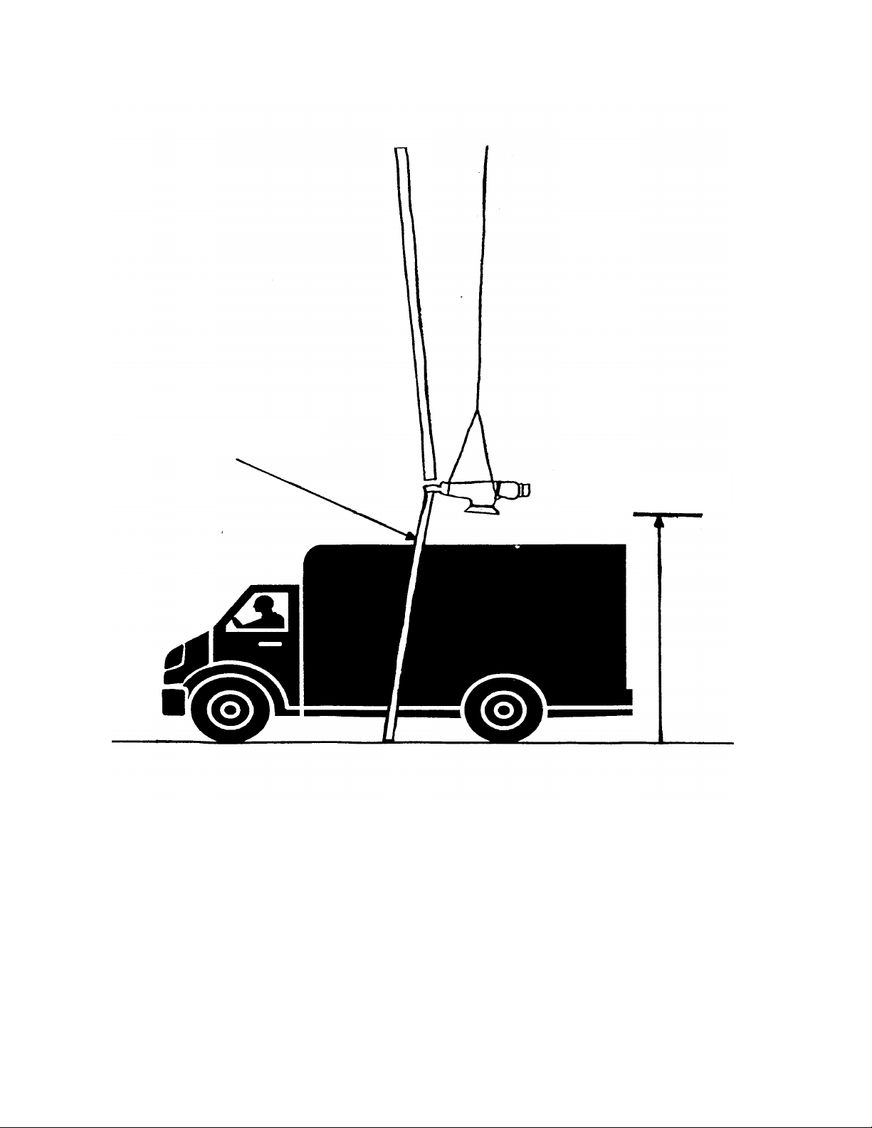
6.0 Tower and Wind Turbine Generator Installation
Third Blade Attached
49
APPROX. 13 Ft
Figure 6-14 Third blade attachment
CAUTION
THE PARKING BRAKE MUST BE PROPERLY ENGAGED,
TO LOCK ALL ROTATING PARTS INTO POSITION,
PRIOR TO LIFTING THE WIND TURBINE GENERATOR.
NOTICE: Use of the material contained in this document is subject to the warning on page Iv and the disclaimer
on page v of this document.
DOC012R02 AOC 15/50 User Manual Nov 2001
Page 58

6.0 Tower and Wind Turbine Generator Installation
50
6.6 Lifting and Securing the Wind Turbine
ONLY TRAINED AND QUALIFIED TECHNICIANS SHOULD
ATTEMPT TO CLIMB A WIND TURBINE TOWER AND SHOULD
USE OSHA/ANSI APPROVED PRACTICE AND EQUIPMENT. ANY
ACTIVITIES WHERE PERSONS COULD BE SUBJECT TO A FALL
OF SIX FEET OR MORE SHOULD BE PERFORMED USING
APPROPRIATE FALL PROTECTION EQUIPMENT FASTENED TO
A SECURE ANCHOR POINT. SEE CHAPTER 3 FOR A
DESCRIPTION OF SAFETY EQUIPMENT AND SECURE ANCHOR
POINTS.
A CLEARLY IDENTIFIED PERSON SHOULD BE DESIGNATED
LIFT COORDINATOR. THE LIFT COORDINATOR SHOULD
DIRECT ALL EQUIPMENT AND PERSONNEL DURING THE LIFT.
WARNING
The technicians on the tower, waiting to receive the wind turbine generator, need to be secured
below the top of the tower, in case the machine swings or shifts unexpectedly. They should not
attach themselves to the wind turbine generator until it is securely bolted to the tower.
The wind turbine generator should be lifted above the top of the tower, controlling the swing and
direction via the taglines. Once it is approximately aligned with the top of the tower, it should be
lowered slowly onto the top tower flanges. A large drift pin may be necessary to align bolt holes
between the tower top casting and the tower flanges.
The bolts, with a washer under the head, should be inserted from the bottom up through each bolt
hole in the tower flange and through the one in the tower top casting. Each bolt should then be
secured with a washer and nut from above, making sure that at least one nut on each flange is
snug tight. Since the self-locking nuts require a significant effort to turn, one can shorten the
crane time by using temporary, non-locking nuts. These must be replaced with lock nuts
IMMEDIATELY after the crane has been released.
Once all bolts have been inserted, their locking nuts need to be tightened with a ratchet and
extension until snug. The tower top lock nuts should be torqued to 810 Nm (600 ft-lbs), using a
1 7/16" socket torque wrench and 1½" combination wrench.
To remove the taglines, the parking brake needs to be released and each blade pulled down in
turn until it is pointing straight down and can be reached from the tower climbing leg; the
taglines can be unclipped after which the parking brake should be re-engaged.
NOTICE: Use of the material contained in this document is subject to the warning on page Iv and the disclaimer
on page v of this document.
DOC012R02 AOC 15/50 User Manual Nov 2001
Page 59

6.0 Tower and Wind Turbine Generator Installation
WARNING
THE PARKING BRAKE OF THE WIND TURBINE SHOULD NEVER
BE LEFT DISENGAGED, AS THIS MAY CAUSE SEVERE INJURY.
51
WIND TURBINE COMPLETE INSTALLATION IN MOROCCO
NOTICE: Use of the material contained in this document is subject to the warning on page Iv and the disclaimer
on page v of this document.
DOC012R02 AOC 15/50 User Manual Nov 2001
Page 60

52
NOTICE: Use of the material contained in this document is subject to the warning on page Iv and the disclaimer
on page v of this document.
DOC012R02 AOC 15/50 User Manual Nov 2001
Page 61

Photo Courtesy of
53
7.0 Electrical Installation
BED
UTILITY INTERFACE
NOTICE: Use of the material contained in this document is subject to the warning on page Iv and the disclaimer
on page v of this document.
DOC012R02 AOC 15/50 User Manual Nov 2001
Page 62

7.0 Electrical Installation
54
The following sections discuss the wind turbine wiring and utility connection requirements
and procedures. Wire connections to the three-phase control box, dynamic brake boxes
and twist cable junction box are site specific, but should follow the general guidelines and
wiring drawings available from AOC.
7.1 Electrical Interface to Utility
The utility interface is site specific and must be coordinated with the local utility or other
responsible party. A kWh meter for each machine is recommended.
The wind turbine may be interfaced with a preexisting low voltage 480V 60Hz (400V 50Hz)
supply or it may require its own step up transformer to the system distribution voltage.
• Interface at the 400/480 VAC level:
For single wind turbine installations the wind turbine can be interfaced directly with the
480/400 VAC utility system, if sufficient transformer capacity exists (75 kVA per
turbine). This also applies to commercial and industrial installations with an adequately
sized 480/400 VAC panel and distribution system. The wind turbine should be on a
dedicated circuit breaker/fuse of proper capacity rating.
• Interface at voltage levels greater than 480/400 VAC:
For single or multiple wind turbine installations it may be necessary and/or desirable to
install a step up transformer between the 480/400 VAC wind turbine and the higher
voltage utility system. For example, in a single unit installation interfacing with a 13.8
kV utility system, a minimum 75 kVA transformer with a 13.8 kV/480V ratio would be
necessary. Since wind turbine output is variable, care must be taken to properly size the
step-up transformer. The winding configuration may also affect system performance.
The AOC 15/50 generator is WYE connected. The interfacing transformer is typically
connected with WYE primary and DELTA secondary.
Figure 7-1 illustrates the simplest form of a utility interface. Utility interconnection should be
specifically engineered for each site. This manual only suggests installation procedures from the
control box to the wind turbine. Applicable national and local codes must be followed. Careful
research and consultation during the planning stage can avoid expensive and dangerous mistakes.
A licensed electrician may be required to install all interconnection wiring. See Appendix M for
details on wire sizing.
NOTICE: Use of the material contained in this document is subject to the warning on page Iv and the disclaimer
on page v of this document.
DOC012R02 AOC 15/50 User Manual Nov 2001
Page 63

7.0 Electrical Installation
55
NOTICE: Use of the material contained in this document is subject to the warning on page Iv and the disclaimer
on page v of this document.
DOC012R02 AOC 15/50 User Manual Nov 2001
Page 64

7.0 Electrical Installation
56
CAUTION
AFTER THE POWER COLLECTION INTERFACE HAS BEEN
INSTALLED, ALL POWER CABLES AND WIRES TO THE WIND
TURBINE MUST BE DE-ENERGIZED. ALL ELECTRIC
DISCONNECTS FEEDING INTO THE WIND TURBINE MUST BE
LOCKED OUT AND TAGGED OUT.
7.2 Wiring and Cable Requirements
The following sections discuss the power, control and anemometer cable requirements.
7.2.1 Power and Control Cable
The power cable for an AOC 15/50 must be of a sufficient ampacity rating to carry the rated
generator current (86 Amperes). The National Electrical Code and the IEC Code list the
ampacity of various cable types.
The minimum cable sizes (see Appendix M) were calculated based on general assumptions
regarding service transformer rating and utility line capacity. Cable sizes were also selected to
take varying distances between the tower and control boxes into account. They are meant for
general planning only and should not replace site specific electrical engineering.
The power cable must be of appropriate insulation and construction to satisfy national and local
electrical code specifications for the specific distribution system. AOC does not recommend the
use of direct buried cable, unless it is armored, due to the increased potential for faults.
It is necessary to consider the economics associated with increasing power cable size from the
minimum required, in order to increase the net energy output (in kWh) of the wind system
through reduced line losses. The increase in revenue from a larger cable must be weighed
against its higher initial cost. Determining the optimum cable size requires the following:
• Consideration of initial expenditures
• Effects of line loss on kWh production
• Projections of kWh production over time
• Interest rates as a reference in determining the economic value of increased initial
investment
Figure 7-2 depicts the typical layout of the electrical enclosures with the dynamic brake boxes
located near the main enclosure. Whenever holes (knockouts) are drilled through electrical boxes
for a conduit installation the edges of the holes must be coated to prevent adverse corrosion.
Please contact a professional engineer, AOC or an authorized representative, for further
assistance in designing a suitable power distribution system.
NOTICE: Use of the material contained in this document is subject to the warning on page Iv and the disclaimer
on page v of this document.
DOC012R02 AOC 15/50 User Manual Nov 2001
Page 65

7.0 Electrical Installation
57
NOTICE: Use of the material contained in this document is subject to the warning on page Iv and the disclaimer
on page v of this document.
DOC012R02 AOC 15/50 User Manual Nov 2001
Page 66

7.0 Electrical Installation
58
7.2.2 Anemometer Mast and Cable Wiring
The AOC 15/50 uses a dual anemometer based control system for increased reliability. Figure 73 shows a typical anemometer. The cable between each of the two anemometers and the control
enclosure must have the following characteristics:
• Consist of at least two conductors, #22 AWG or larger
• Be twisted and shielded against electrical interference
• Be resistant to ultraviolet radiation due to exposure on the tower
• Be rated for protected direct burial if not run in a conduit
• Be suitable for the ambient temperature and other conditions expected at site
To meet code requirements, the anemometer cable insulation must carry a 600V rating if it is to
be run for any distance in the same conduit or raceway as the wind turbine power cable. For
most sites BELDEN 9501 cable will be suitable for this purpose.
NOTE: Cable shields should only be grounded at the turbine control panel. Any other grounding
scheme may lead to multiple grounds that could affect circuit function.
The anemometer boom should be mounted at the third set of brace clips below the topmost tower
section, approximately 10 m (32 ft) from the top of the tower. It should be approximately
perpendicular to the prevailing wind direction, with the anemometer masts vertical. Each
anemometer should be fitted with one anemometer cable and attached to the mast. The cotter pin
has to be inserted to secure the anemometer to its mast. The anemometers cables should be
routed to a common point near one of the two adjacent tower legs and be attached to the
anemometer masts using UV protected tie wraps. Each cable should be looped, approximately
30 cm (12 inches) across, before attaching it to the tower leg. The loop will provide extra cable
for servicing. The two cables should be routed down one of the tower legs to either the twist
cable junction box or directly to the control box. See Appendix B for additional details.
Figure 7-3 Anemometer
NOTICE: Use of the material contained in this document is subject to the warning on page Iv and the disclaimer
on page v of this document.
DOC012R02 AOC 15/50 User Manual Nov 2001
Page 67

7.0 Electrical Installation
Photo Courtesy of
59
7.3 Control Box Connections
Wires should be run in a conduit to the control box based on convenience, safety and applicable
standards. Non-NEMA 4 electronic enclosures must be housed in a weatherproof service
structure. However, it is recommended that all enclosures be housed in a weatherproof structure
to facilitate maintenance in all weather conditions. Wires from the control box to the tower base
should run in a conduit. Rigid metal conduit should be buried to a minimum depth of 92 cm (36
inches) and approved non-metallic direct burial conduit, to a minimum depth of 46 cm (18
inches) or 61 cm (24 inches) for roadways. Refer to the National Electrical Code, International
Electrotechnical Commission standards and local inspectors for site specific requirements.
All wires between the control box, the dynamic brake capacitor box and the dynamic brake
resistor box must be properly contained in conduits and be terminated correctly in the control
box. When terminating wires in screw lugs, torque, release torque and retorque the lug screw to
ensure the wire will not pull out of the lug connection. See Appendix M for wire connections.
NOTICE: Use of the material contained in this document is subject to the warning on page Iv and the disclaimer
DOC012R02 AOC 15/50 User Manual Nov 2001
KEA
Figure 7-5 Control box at Kotzebue Electric Association
on page v of this document.
Page 68

7.0 Electrical Installation
Photo Courtesy of
60
7.4 Twist Cables and Junction Box
The twist cable junction box should be mounted on the inside of a tower leg approximately 3.7 m
(12 feet) above the tower base. This height may need to be adjusted, depending on twist cable
length. The vertical cable droop must be approximately 1.8 m (6 ft) (see Appendix B).
Two Unistrut, split pipe clamps are used to secure the box to the tower leg. The box should be
oriented with its door facing towards the center (inside) of the tower (see Appendix B).
The two twist cables can be connected to the junction box. Conduit should be installed between
the twist cable junction box and the control enclosure. Please note that whenever holes are
drilled through electrical boxes for conduit installation the edges of the holes must be coated to
prevent adverse corrosion. Failure to adequately coat metal may lead to early deterioration of the
enclosure.
NOTICE: Use of the material contained in this document is subject to the warning on page Iv and the disclaimer
DOC012R02 AOC 15/50 User Manual Nov 2001
KEA
7-5 Turbine, tower and anemometer boom
on page v of this document.
Page 69

7.0 Electrical Installation
61
8.0 Function Tests and Commissioning
NOTICE: Use of the material contained in this document is subject to the warning on page Iv and the disclaimer
on page v of this document.
DOC012R02 AOC 15/50 User Manual Nov 2001
Page 70

8.0 Function Tests and Commissioning
62
The following section describes the procedures for testing a wind turbine’s functions before it is
officially commissioned.
8.1 Function Tests and Commissioning
Prior to placing the wind turbine into initial service and after any maintenance and/or repair
work, the following must be carried out and the commissioning/checkout test sheet must be
completed (see Appendix H).
WARNING
DO NOT ATTEMPT TO PERFORM
COMMISSIONING UNLESS YOU HAVE BEEN
PROPERLY TRAINED AND ARE EXTREMELY
FAMILIAR WITH THE OPERATION OF THE
WIND TURBINE AND ITS CONTROLS. IT IS
HIGHLY RECOMMENDED THAT AN AOC
REPRESENTATIVE PERFORM THE
COMMISSIONING OF THE MACHINE.
• Power up the control system for the first time using the following steps.
1. Set all control switches to OFF
2. Open the three 15 Amp circuit breakers on the 120V side of the control
transformer: 1CB, 2CB, 3CB
3. Open the three-pole, 3 Amp breakers on the 480V bus which reads the control
transformer and the grid monitor: 4CB, 5CB, 6CB
4. Energize the 480V bus from the utility network
5. Close the three-pole, 3 Amp breakers to energize the control transformer: 4CB,
5CB, 6CB
6. Check for 120 VAC output on the control transformer
7. Close the three 15 Amp circuit breakers on 120V side of the control transformer:
1CB, 2CB, 3CB
8. Observe panel lights. They should run through a flash sequence and then turbine
ready light should light up and remain on
9. Carry out a generator test (See Section 8.2)
• Verify that the parking brake releases properly by conducting a parking brake release test
(See Section 9.3.2)
• Verify that the anemometer signal is present and presents a realistic value (See Section
9.3.5)
• Verify that the speed sensor circuit is working properly (See Section 9.3.6)
• Test operation of the dynamic brake by running a dynamic brake test (See Section 9.3.4)
• Test normal start-up and manual shut down (See Section 9.3.7).
NOTICE: Use of the material contained in this document is subject to the warning on page Iv and the disclaimer
on page v of this document.
DOC012R02 AOC 15/50 User Manual Nov 2001
Page 71

8.0 Function Tests and Commissioning
63
• Test emergency shut down (See Section 9.3.8)
• Test low wind shut down (See Section 9.3.9)
It is a good idea to observe the wind turbine running under normal conditions to verify its correct
operation. After it has been observed in normal winds, it may be signed off and formally
commissioned.
8.2 Generator Test
Each generator should be run briefly to determine proper phase rotation. The test can be carried
out during commissioning by rotor jogging the wind turbine briefly and observing the rotation of
the main shaft. If the phase rotation is correct the turbine will rotate counter clockwise when
looking upwind. If the direction of rotation is incorrect, any two of the phase leads should be
changed over and the test repeated. The only wires to be changed in the control box are the
phase leads to the turbine, TB2.
NOTICE: Use of the material contained in this document is subject to the warning on page Iv and the disclaimer
on page v of this document.
DOC012R02 AOC 15/50 User Manual Nov 2001
Page 72

8.0 Function Tests and Commissioning
64
NOTICE: Use of the material contained in this document is subject to the warning on page Iv and the disclaimer
on page v of this document.
DOC012R02 AOC 15/50 User Manual Nov 2001
Page 73

Part III
65
Part III
NOTICE: Use of the material contained in this document is subject to the warning on page Iv and the disclaimer
on page v of this document.
DOC012R02 AOC 15/50 User Manual Nov 2001
Page 74

Part III
66
NOTICE: Use of the material contained in this document is subject to the warning on page Iv and the disclaimer
on page v of this document.
DOC012R02 AOC 15/50 User Manual Nov 2001
Page 75

67
9.0 Wind Turbine Operation
AOC 15/50 Controller box
NOTICE: Use of the material contained in this document is subject to the warning on page Iv and the disclaimer
on page v of this document.
DOC012R02 AOC 15/50 User Manual Nov 2001
Page 76

9.0 Wind Turbine Operation
68
WARNING
BEFORE ENERGIZING THE SYSTEM, CAREFULLY REVIEW
THIS CHAPTER AND ENSURE THAT ALL REQUIREMENTS ARE
COMPLIED WITH. IMPROPER PROCEDURES IN ENERGIZING
THE SYSTEM MAY CAUSE SEVERE INJURY OR DEATH FROM
SHOCK.
9.1 Normal Operation
This section contains a description of the operational functions of the wind turbine in normal
conditions. Normal conditions are defined as those in which the wind turbine was designed to
operate in (see Appendix A for the design specifications).
The six switches on the front panel of the control box control the wind turbine (see Figure 9-1).
The control system inputs available to the operator via the switches are listed below.
Function
Emergency
Stop
Turbine
Test/Off/On
Parking Brake
Release
Type
Maintained Overrides all PLC control to disconnect the turbine from the utility
network. Requires an operator to manually reset the turbine control
system.
Maintained OFF – parks the turbine with all brakes deployed.
OFF to ON – resets any fault indicator.
ON – allows the wind turbine to start, conditions permitting.
TEST – allows the parking brake release, rotor jog and dynamic brake
test switches to become active.
Maintained Releases the parking brake and allows the rotor to turn freely.
Description
Rotor Jog
Dynamic
Brake Test
Condensation
Heater On/Off
Maintained Releases all brakes and connects the turbine to the grid.
Maintained Used with the rotor jog function to delay the operation of the tip and
parking brakes in order to assess the performance of the dynamic
brake.
Maintained Energizes condensation heater.
Table 9.1-1 Operator input switches
The operation of these switches is described in detail in the following sections.
NOTICE: Use of the material contained in this document is subject to the warning on page Iv and the disclaimer
on page v of this document.
DOC012R02 AOC 15/50 User Manual Nov 2001
Page 77

9.0 Wind Turbine Operation
69
9.1.1 Turbine TEST/OFF/ON
Turbine OFF:
This is the normal OFF mode. All brakes are deployed with the brake relays de-energized. The
main contactor is de-energized, disconnecting the turbine from the grid. The PLC disregards all
other sensors while the switch is set to OFF. The brake light should be ON. The high wind,
brake cooling cycle or other fault lights may also be ON, subject to conditions.
Turbine ON:
This is the normal ON mode. The PLC continuously monitors the system parameters for wind
turbine readiness and for fault conditions.
In the absence of faults, the wind turbine is in the ready mode and the ready light will be ON.
At low wind speeds the brake light will be ON indicating that the wind turbine is parked. When
the wind speed average is above 4.9 m/s (11 mph) the PLC will release the brakes allowing the
turbine to freewheel up to speed and come on line as follows:
• The brake relays are energized.
• The tip brake magnets are energized and hold the tip brake plates closed.
• The dynamic brake relay is energized, disconnecting the dynamic brake resistors and
capacitors from the generator output.
• The parking brake solenoid is energized, releasing the high-speed shaft, thereby allowing
it to rotate freely.
• In sufficiently strong winds the wind turbine freewheels up to speed and is monitored by
the controller.
• When the high-speed shaft reaches 1500 rpm (50 Hz wind turbine) or 1800 rpm (60 Hz
wind turbine), the PLC energizes the main contactor connecting the generator to the grid
and turns the online light ON.
If the wind speed average drops below 3.6 m/s (8 mph), the wind turbine will go through a
normal shutdown procedure as follows:
• The main contactor disconnects from the grid.
• The tip brake and dynamic brake relays deploy.
• The brake light lights up.
• The parking brake relay deploys after 4 seconds.
• The brake cooling cycle light lights up; the cooling cycle typically runs for 15 minutes.
The brake cooling cycle allows the dynamic brake resistors and parking brake to cool to ambient
temperatures. During this period, the PLC overrides the wind speed sensor, thereby preventing
the wind turbine from reconnecting to the grid. At the end of the cooling cycle, the PLC reverts
to the normal control mode with the wind turbine ready light ON.
NOTICE: Use of the material contained in this document is subject to the warning on page Iv and the disclaimer
on page v of this document.
DOC012R02 AOC 15/50 User Manual Nov 2001
Page 78

9.0 Wind Turbine Operation
70
The PLC monitors the system parameters continuously as shown in Table 9.1-2. When a system
parameter is out of range or a fault has been registered, the PLC takes appropriate action by
disconnecting and either parking or freewheeling the wind turbine. Following this, it will
continue to monitor the parameters and faults, resetting the system once they have cleared.
Rotor over-speed faults and parking brake undercurrent faults require to be reset manually. The
turbine TEST/OFF/ON switch must be switched to OFF first and then back to ON; it is the
change from OFF to ON that resets the faults. All other faults reset automatically once the
cause of the fault has cleared. An optional low power fault is included in some controllers to
shut down the wind turbine, should the output drop significantly below the values expected at a
given wind speed. This fault resets automatically, unless it has occurred three times within 75
minutes, in which case a manual reset is required.
During any fault related shutdown, the tip and dynamic brakes activate immediately, with the
dynamic brake providing a large portion of the braking torque. Application of the parking brake
is normally delayed until the rotor has slowed down sufficiently using the tip and the dynamic
brakes. During a loss of utility power to the controller, all brakes are applied simultaneously.
Thirty three percent of the dynamic brake capacitance is disabled to allow an immediate torque
contribution by the parking brake, keeping the overall braking torque within safe limits.
Turbine TEST:
When set to TEST the parking brake, dynamic brake and rotor jog switches can be energized.
9.1.2 Heater ON
The generator winding and the parking brake heaters prevent condensation from collecting on
the windings and the parking brake, respectively. They can be activated manually at the
operator's discretion when the dew point is high but only when the wind turbine is disconnected
from the grid. When the main contactor is closed, the PLC automatically de-energizes the
heater circuit. An optional transmission heater can be provided for severe cold weather sites.
9.1.3 Parking Brake Release
The parking brake release switch allows the operator to release the parking brake when the wind
turbine is in test mode and no grid faults, over-speed or high winds have been registered. It is
not necessary to release the brake manually during normal operation.
NOTICE: Use of the material contained in this document is subject to the warning on page Iv and the disclaimer
on page v of this document.
DOC012R02 AOC 15/50 User Manual Nov 2001
Page 79

9.0 Wind Turbine Operation
over voltage:
Instrumentation
high speed shaft
from power curve
Grid parameters
Generator Temperature 3 NC thermostats
under voltage: 380-460V
(response time) adj 1-10secs
phase reversal disconnect and park
Rotor Speed 2 speed sensors on
Rotor nominal: 1800rpm
Rotor full load: 1840rpm
Rotor overpower: 1860rpm
Rotor over-speed 1875rpm
Rotor under-speed: 1760rpm
(freewheel option) 1800rpm
(coast up option) < 50rpm after 1 min? < 50rpm after 1 min?
wind in range 11mph - 50mph
Power output
Brake status
brakes applied
parking brake fault
over temperature 145 deg C
phase loss disconnect and park
Wind Speed
low wind 8mph
high wind 50 mph
low power % < set points
400-540V
grid monitor
2 anemometers
watts transducer
plc signal disconnect and park
current sensor disconnect and park
60hz
50hz
350-450V
300-400V
adj 1-10secs
1500rpm
1535rpm
1550rpm
1560rpm
1460rpm
1500rpm
11mph - 50mph
8mph disconnect and park or freewheel
50 mph
% < set points
from power curve
145 deg C
disconnect and park
disconnect and park
if no faults connect to grid turbine on line
disconnect and park
disconnect and park
disconnect and park
disconnect and freewheel
disconnect and park
if no faults release brake
disconnect and park
disconnect and park
disconnect and park
action
reset when cleared
automatic
automatic
automatic
automatic
automatic
manual
automatic
automatic
automatic
automatic
automatic high wind speed
automatic
automatic
manual
automatic
Table 9.1-2 PLC control system monitoring
71
status lights
grid monitor light
grid monitor light
grid monitor light
grid monitor light
rotor overpower
rotor overspeed
rotor overspeed flashing
brakes applied
brakes applied flashing
generator thermal alarm
NOTICE: Use of the material contained in this document is subject to the warning on page Iv and the disclaimer on page v of this document.
DOC012R02 AOC 15/50 User Manual Nov 2001
Page 80

9.0 Wind Turbine Operation
72
9.1.4 Rotor Jog
With the wind turbine in test mode the rotor jog switch will allow the operator to release the
brakes and energize the main contactor, provided no high winds or fault conditions have been
registered. It is not necessary to use the parking brake release switch with the rotor jog, as the
rotor jog switch automatically releases all brakes before energizing the main contactor
9.1.5 Dynamic Brake
With the wind turbine in test mode, the dynamic brake switch allows the operator to test the
dynamic brake. When the switch is set to ON, only the dynamic brake is used for braking,
allowing its braking power to be observed. The dynamic brake test should be carried out only
during periods of low wind and be limited to a maximum of 10 seconds. The dynamic brake
resistors should be allowed to cool to ambient temperatures before repeating the test.
9.1.6 Operator Interface Indicating Lights
LED indicators are provided to indicate various wind turbine states (see Table 9.1-3). Unless a
manual reset is stated, the turbine will automatically reset once a fault has cleared. Meters
displaying wind speed, power output and wind turbine run time are available as options.
9.1.7 PLC Description
The PLC controls the AOC 15/50. The primary parameters measured for determining wind
turbine performance and control are wind speed and generator rotor speed. Each wind speed
signal is converted to an analog voltage and read by the PLC through analog input channels.
The wind turbine output power is determined by measuring the generator rpm and calculating
the power level based on rotor slip. The generator rotor speed is measured using two proximity
switches, each with its own frequency to voltage (F/V) converter, and a timing gear. Optionally,
a power transducer signal may be measured by the PLC. Other system parameters, such as
utility network status, are relay type signals from external devices and are read through the PLC
digital input channels. The PLC also has a serial communications port, which can be interfaced
to some SCADA systems.
Figure 9-2 shows the inside of a typical turbine controller, Figure 9-3 the capacitor box and
Figure 9-4 the PLC.
NOTICE: Use of the material contained in this document is subject to the warning on page Iv and the disclaimer
on page v of this document.
DOC012R02 AOC 15/50 User Manual Nov 2001
Page 81

9.0 Wind Turbine Operation
Table 9.1-3 AOC 15/50 System indicating lights
73
Function
Color
Description
Turbine Ready Green ON: Turbine can be connected to the utility network.
Turbine On
Green ON: Turbine is connected to the utility network.
Line
Brakes Applied Red
ON: Any of the brakes are deployed.
OFF: When parking brake is released during parking brake release
test.
Brake Cooling
Cycle
Red
ON: Turbine is waiting for brakes to cool (typically 15 minutes).
FLASHING: Parking brake undercurrent fault. Must be reset
manually.
Grid Fault
Red
ON: Monitor detected over/under voltage, phase reversal, loss of
phase. Stays on for duration of brake cooling cycle.
Generator
Thermal Alarm
Red
ON: Generator internal thermal switch indicates an elevated
temperature. Must be reset manually.
FLASHING: Softstart thermal switch indicates an elevated
temperature. Must be reset manually.
Rotor
Overspeed
Red
ON: Maximum rotor speed exceeded (1875 rpm for 60 Hz). Must
be reset manually.
FLASHING: Difference of over 20 rpm between the two speed
sensors. This does not shut down the turbine.
Rotor
Overpower
High Wind
Speed
Red
Red
ON: Generator maximum power rating exceeded (1550 rpm for
50 Hz and 1860 rpm for 60 Hz ).
ON: Wind speed has exceeded program limit (typically 22.3 m/s or
50 mph). Stays on for duration of brake cooling cycle.
Spare Red ON: Low power shut down. Turbine power output is low for giving
wind speed.
FLASHING: Three low power shut downs have occurred within
75 minutes. Must be reset manually.
NOTICE: Use of the material contained in this document is subject to the warning on page Iv and the disclaimer
on page v of this document.
DOC012R02 AOC 15/50 User Manual Nov 2001
Page 82

9.0 Wind Turbine Operation
•
GENERATOR THERMAL ALARM • SPARE (low power option)
74
TURBINE READY • TURBINE ON LINE
•
BRAKES APPLIED • BRAKE COOLING CYCLE
•
HIGH WIND SPEED • ROTOR OVERSPEED
•
GRID FAULT • ROTOR OVERPOWER
•
Turbine
TEST OFF ON
Condensation
Heater
OFF ON
Dynamic
Rotor Jog
OFF ON
Brake
OFF ON
Park Brake
Release
OFF ON
Figure 9-1 - Diagram of the system indicating lights and switches
NOTICE: Use of the material contained in this document is subject to the warning on page Iv and the disclaimer
on page v of this document.
DOC012R02 AOC 15/50 User Manual Nov 2001
Page 83

9.0 Wind Turbine Operation
Figure 9-2 Inside of a typical turbine controller Figure 9-3 Capacitor box
75
Figure 9-4 PLC
THE SOFTWARE THAT OPERATES THE PLC IS DESIGNED BY
AOC FOR EACH SPECIFIC APPLICATION, TO PROVIDE SAFE
AND EFFICIENT WIND TURBINE CONTROL. MODIFICATIONS
TO THE SOFTWARE, NOT AUTHORIZED BY AOC, COULD
RESULT IN WIND TURBINE MALFUNCTION, DAMAGE TO IT
AND/OR PERFORMANCE HAZARDS. AOC IS NOT
RESPONSIBLE FOR ANY DIRECT OR CONSEQUENTIAL
DAMAGES OR ANY INCIDENTAL EXPENSE, INCLUDING THE
LOSS OF POWER GENERATION, RESULTING FROM ANY SUCH
MODIFICATIONS.
WARNING
NOTICE: Use of the material contained in this document is subject to the warning on page Iv and the disclaimer on
page v of this document.
DOC012R02 AOC 15/50 User Manual Nov 2001
Page 84

9.0 Wind Turbine Operation
9.1.7.1 PLC Inputs
The following tables list and describe the input signals to the PLC controlling the AOC 15/50.
Function Description
Anemometer #1
Anemometer #2
Generator speed proximity
switches #1 and #2
0-5 VDC analog signal corresponds to 0-45 m/s (0-100 mph).
0-5 VDC analog signal corresponds to 0-45 m/s (0-100 mph).
Pulse input to F/V converter. 1-5 VDC signal corresponds to 0
to 2,000 rpm.
76
Watts Transducer Control
Function Description
Generator thermal switch
Grid Voltage monitor
Grid Frequency monitor
(optional)
Master control relay
Turbine OFF/TEST/ON
Rotor jog switch
Parking brake release switch
Dynamic brake test switch
Remote start (optional)
Remote line start (optional)
0-5 VDC analog signal corresponds to 0-8 kW.
Table 9.1-6 PLC low level analog inputs
3 series connected switches within the generator.
Relay contact indicating loss of phase, phase reversal and under
or over voltage.
Relay contact indicating over or under frequency.
Used to determine whether or not the turbine has been reset.
Maintained switch parks or starts the turbine. In test position it
allows special test functions to become active.
Maintained switch releases the brakes and connects the turbine
to the grid. Available in test mode.
Maintained switch releases the parking brake. Available in test
mode.
Maintained switch used in combination with the rotor jog
switch to delay operation of the tip and parking brakes to verify
the effectiveness of the dynamic brake. Available in test mode.
Allows a turbine to be started by another turbine's controller; its
own anemometers (if equipped) are ignored.
Causes an across the line start if remote start is true.
NOTICE: Use of the material contained in this document is subject to the warning on page Iv and the disclaimer
on page v of this document.
DOC012R02 AOC 15/50 User Manual Nov 2001
Page 85

9.0 Wind Turbine Operation
Table 9.1-6 PLC AC inputs
77
9.1.7.2 PLC Outputs
The following tables describe the PLC outputs needed to control the AOC 15/50. AC outputs
are used to control interposing relays and contactors for the various wind turbine functions. DC
outputs are used for driving the LED indicators.
Function Description
Dynamic brake contactor Normally closed contacts are used to apply brake on loss of
power.
Parking brake relay Normally open contacts are used to apply brake on loss of
power.
Tip brake relay Normally open contacts are used to apply brake on loss of
power.
Generator contactor Connects generator to utility network.
Condensation heater relay Provides 150 W of heating to the generator and 50 W to the
parking brake to expel condensation.
Transmission heater relay Provides 75 W of heating to the transmission.
Remote start output relay
Closure of N.O. contacts causes downstream turbine to start.
(optional)
Oil heater (optional) Provides power to gearbox oil heater.
Softstart relay (optional) Closure of N.O. contacts bypasses softstart resistor
Table 9.1-7 PLC AC outputs
9.1.8 Control Systems Options
•
Soft-start options – resistor or electronic softstart.
•
Enclosure heater (typically 200 Watt).
•
Drip-proof NEMA 3 and weatherproof enclosures NEMA 4.
•
Tropical, marine (stainless steel) and arctic conditioned enclosures (heater and
insulation).
•
Enhanced display functions and diagnostics.
§
Over/under frequency.
§
G59 compatible grid monitor for UK sites.
§
PLC LCD display.
§
Wind turbine run time meter.
•
Remote communications and data acquisition via RS 422 port.
9.2 Emergency Operation
In case of any emergency, an emergency cutoff switch is provided externally on the control box.
See Section 3.8 for emergency procedures.
NOTICE: Use of the material contained in this document is subject to the warning on page Iv and the disclaimer
on page v of this document.
DOC012R02 AOC 15/50 User Manual Nov 2001
Page 86

9.0 Wind Turbine Operation
78
Emergency Stop Pushed In:
The emergency stop switch overrides all other switches. With the emergency stop pushed in,
the wind turbine should come to a complete stop and de-energize immediately. All brakes
deploy, the relays de-energize and the main contactor opens. In this mode, there is no power to
the PLC output cards and the relays can not be energized. The wind turbine disconnects from
the grid and remains so until the emergency stop is reset manually (pulled out).
Emergency Stop Pulled Out:
With the emergency stop switch pulled out, all the other switches can be operated.
9.3 Test Operation
The following sections show the procedures used when testing the wind turbine functions after
installation and/or after any maintenance has been performed.
Before placing the wind turbine into service for the first time and after any maintenance and/or
repair work, the following tests must be carried out and the commissioning/checkout test sheet
(see Appendix G) must be completed.
9.3.1 Power Up
1. Set all control switches to OFF.
2. Open the three 15 Amp circuit breakers on the 120 V side of the control transformer
(1CB, 2CB, 3CB).
3. Open the three-pole, 3 Amp breakers on the 480 V bus which reads the control
transformer and the grid monitor (4CB, 5CB, 6CB).
4. Energize the 480 V bus from the utility network.
5. Close the three pole, 3 Amp breakers to energize the control transformer (4CB, 5CB,
6CB).
6. Check for 120 VAC output on the control transformer.
7. Close the three 15 Amp circuit breakers on 120 V side of the control transformer (1CB,
2CB, 3CB).
8. Observe the panel lights, which should run through a flash sequence after which the
turbine ready light should light up and remain on.
9.3.2 Parking Brake Release Test
1. Set the turbine test switch to TEST.
2. Set the parking brake release switch to ON.
3. Observe the rotor movement.
NOTICE: Use of the material contained in this document is subject to the warning on page Iv and the disclaimer
on page v of this document.
DOC012R02 AOC 15/50 User Manual Nov 2001
Page 87

9.0 Wind Turbine Operation
4. Reset the turbine test switch to OFF.
5. Observe the wind turbine; the parking brake should engage and the rotor should stop.
WARNING
THIS TEST SHOULD ONLY BE CARRIED OUT IN LOW WIND
CONDITIONS.
9.3.3 Rotor Jog Test
1. Set the turbine test switch to TEST.
2. Turn the rotor jog switch to ON, connecting the wind turbine to the grid.
3. The rotor should turn counterclockwise when viewed looking upwind.
4. If the sense of the rotation is not correct shut down the system and swap any two of the
480 V leads to the generator to reverse the phase rotation.
5. Reset the rotor jog switch to OFF.
6. Reset the turbine test switch to OFF.
79
9.3.4 Dynamic Brake Test
1. Set the turbine test switch to TEST.
2. Set the dynamic brake switch to ON, disabling the parking brake and tip brakes.
3. Set the rotor jog switch to ON, connecting the wind turbine to the grid.
4. Allow several seconds for the wind turbine to come up to speed (64 rpm).
5. Turn the rotor jog switch to OFF.
6. Observe the wind turbine for any noticeable speed loss.
7. After 10 seconds maximum, switch the dynamic brake switch to OFF to apply the tip
brakes and the parking brake.
9.3.5 Anemometer Signal Test
1. With some measurable amount of wind (> 4.5 m/s (10 mph)), determine the voltage
(DC) across the terminals 5 (-) and 6 (+) with a multimeter on each NRG cube
simultaneously.
2. The voltage should read between 0 and 5 VDC corresponding to a wind speed of 0 - 44.7
m/s (0 - 100 mph). Both anemometers should read approximately the same values. See
Appendix H for voltage to wind speed conversion.
NOTICE: Use of the material contained in this document is subject to the warning on page Iv and the disclaimer
on page v of this document.
DOC012R02 AOC 15/50 User Manual Nov 2001
Page 88

9.0 Wind Turbine Operation
9.3.6 Speed Sensor Signal Test
1. Perform a rotor jog.
2. Measure the output voltage from the frequency to voltage converter. It should be
approximately 3.75 VDC (50 Hz) or 4.5 VDC (60 Hz).
9.3.7 Normal Start-up/Shut-down Test
1. In 5.4 - 9 m/s (12 - 20 mph) winds, turn the turbine switch to ON.
2. The rotor should accelerate and the main contactor should close.
3. Turn the turbine switch to OFF.
4. When the tip brakes release, the turbine should come to a complete stop and de-energize.
9.3.8 Emergency Shut down Test
1. In 5.4 - 9 m/s (12 - 20 mph) winds, turn the turbine switch to ON.
2. The rotor should accelerate and the main contactor should close.
3. Depress the emergency stop button.
4. When the tip brakes release, the turbine should come to a complete stop and de-energize.
80
9.3.9 Low Wind Shut Down Test
1. In 5.4 - 9 m/s (12 - 20 mph) winds, turn the turbine switch to ON.
2. The rotor should accelerate and the main contactor should close.
3. Observe shut down when wind speeds fall below 5.4 m/s (12 mph). If necessary, an
AOC representative can simulate low wind speed electronically.
4. The tip brakes should release and the wind turbine should come to a complete stop and
de-energize.
9.4 Environmental Considerations
The following sections identify environmental considerations associated with the operation and
maintenance of the AOC 15/50.
9.4.1 Corrosion
The primary source of corrosion is salt air, which is prevalent in marine environments and is
particularly critical when combined with warm temperatures. A secondary source of corrosion,
with more subtle symptoms, consists of airborne pollution, such as acid rain and industrial
pollutants.
NOTICE: Use of the material contained in this document is subject to the warning on page Iv and the disclaimer
on page v of this document.
DOC012R02 AOC 15/50 User Manual Nov 2001
Page 89

9.0 Wind Turbine Operation
81
During routine inspections in aggressive environments, particular attention should be directed at
locating oxidation and blistered paint. If any such surface degradation is found, corrective
action should be taken immediately; the corroded layer should be removed and either paint or a
corrosion-inhibiting film, such as Soft Seal, should be applied. The edges of holes (knockouts)
drilled through electrical boxes for conduit installation must also be coated to prevent corrosion.
9.4.2 Lightning
The wind turbine and tower are protected against voltage surges. However, protection from
direct lightning strikes cannot be guaranteed. If the system fails after an electrical storm all
electrical components should be checked. Note that many components can be damaged due to
lightning and the following items have been know to fail due to lightning strikes: anemometers,
shaft speed sensors, generator, 120 VAC and 480 VAC surge suppressors and relays. After a
lightning strike, the entire system, including the interconnect wiring, should be checked. If
possible, power to the system should be turned off prior to an electrical storm and not be
reconnected until the storm has passed. The most common cause of damage to electrical
devices is voltage surges due to lightning strikes to the utility line.
9.4.3 Ice and Snow
Ice or snow will not normally affect wind turbine operation unless it builds up on the blades
and/or tip brakes. If such build-up is uneven, it can cause rotor imbalance, which may lead to
system vibration, if the rotor is allowed to rotate. During periods of potential icing the wind
turbine should, therefore, be switched off.
CAUTION
IN EXTREME CASES ICE BUILD-UP MAY CAUSE DAMAGE
TO THE SYSTEM. THEREFORE, IT IS NOT RECOMMENDED
THAT THE WIND TURBINE BE OPERATED WITH
SIGNIFICANT ICE BUILD-UP.
NOTICE: Use of the material contained in this document is subject to the warning on page Iv and the disclaimer
on page v of this document.
DOC012R02 AOC 15/50 User Manual Nov 2001
Page 90

9.0 Wind Turbine Operation
460 + T
82
Wet snow may affect tip brake operation, possibly causing premature deployment or, in severe
cases, damage due to the additional weight on the tip brake plate. Severe icing may also inhibit
the tip brake from deploying correctly.
Ice build-up on the anemometers can prevent a wind turbine from starting up. If it is already
running, the anemometers may ice up before the blades, indicating conditions in which the wind
turbine should be shut down.
Normally, the ice will melt in a reasonable amount of time. In certain cases, it can be removed
by gently tapping it off the anemometers, the tip brakes and the blades. To do this the machine
must be switched OFF. If there is only a thin layer of ice on the blades, jogging the machine
very briefly may remove it. The anemometers, blades and tip brakes must be free of ice before
switching the turbine ON/OFF/TEST switch to ON. Prior to starting up a wind turbine, which
has ice adhering to the blades, make sure that personnel are protected from any ice that might fly
off them.
9.4.4 Temperature and Elevation
Although calculable, elevation and temperature extremes do not adversely affect a wind
turbine’s operation. The design temperature range is -40°C to +64°C (-40°F to +147°F) with no
altitude constraints.
The power generated by a wind turbine is a function of wind speed and air density. Higher wind
speeds produce more power. Variations in temperature and relative humidity, at any given
altitude, have a more subtle effect. As temperature increases, air density decreases, reducing
energy output. Conversely, at lower temperatures, energy output will increase, proportionally to
the increase in air density. The formula below allows energy output to be corrected, taking
altitude and temperature into consideration.
*
* P = Output Corrected
C
s
C
at
Where Ps is power output at sea level at 15°C (59°F) and Ct and Ca are correction factors for
temperature and altitude. They are defined as follows:
966
=
1000A/
5
19
= .
C
a
C
t
Where T is temperature in °F and A is altitude in feet.
NOTICE: Use of the material contained in this document is subject to the warning on page Iv and the disclaimer
on page v of this document.
DOC012R02 AOC 15/50 User Manual Nov 2001
Page 91

9.0 Wind Turbine Operation
6
460 + 8
83
The example below illustrates the above formula:
If a 50 kW wind turbine generates 50 kW at 13.4 m/s (30 mph) wind speed under
standard conditions, what would the output be at an altitude of 1,980 m (6,500 feet) and
30°C (86°F)?
Solution:
Corrected Output = Standard Output *Ct *Ca
Ps = 50 kW
19
5
=
C
t
1
.95 =
6500/1000
. =
966
C
a
.799 =
Corrected Output = (50kW) (.951) (.799) = 38.0 kW
This approach can also be used, albeit with less accuracy, to correct annual energy (kWh) output
predictions.
9.4.5 Acoustics
The AOC 15/50 has been designed as a low-noise wind turbine. The most significant sources of
noise are the drive train and the turbulence caused by the blades as they pass the tower. An
audible increase in noise may indicate a problem and appropriate measures to diagnose it should
be taken immediately, to prevent damage to the wind turbine. Please note the sounds associated
with a normally operating wind turbine when the machine is first installed; these will provide an
acoustic baseline for future comparisons.
NOTICE: Use of the material contained in this document is subject to the warning on page Iv and the disclaimer
on page v of this document.
DOC012R02 AOC 15/50 User Manual Nov 2001
Page 92

9.0 Wind Turbine Operation
84
NOTICE: Use of the material contained in this document is subject to the warning on page Iv and the disclaimer
on page v of this document.
DOC012R02 AOC 15/50 User Manual Nov 2001
Page 93

Photo Courtesy of
85
10.0 System Monitoring
NOTICE: Use of the material contained in this document is subject to the warning on page Iv and the disclaimer
DOC012R02 AOC 15/50 User Manual Nov 2001
KEA
KOTZEBUE ELECTRIC ASSOCIATION WIND FARM
on page v of this document.
Page 94

10.0 System Monitoring
86
The following sections discuss the various monitoring systems of the AOC 15/50.
10.1 Kilowatt-Hour Meter Applications
Some utilities may require the use of detented, unidirectional kilowatt-hour (kWh) meters: one
to read the energy supplied by the utility and another to read the energy absorbed by it. This
enables the utility to pay the avoided cost rate for the energy it buys and to charge the standard
rate for the energy it consumes. A detented kWh meter can be used to monitor power
production. The most useful information for evaluating system performance is obtained by
comparing the kilowatt-hours generated with the average wind speed over the same period. The
relevant parameters can be measured using a dedicated kWh meter (energy production) and an
anemometer (wind speed).
Net billing refers to the installations where a single kWh meter is allowed to run forwards or
backwards depending upon whether the system is consuming or producing energy. The kWh
meter indicates the net energy flow and energy is valued at the same rate for consumption and
production.
10.2 Anemometers
The AOC 15/50 has two anemometers which are boom-mounted across two tower legs,
approximately 10 m (32 feet) below the tower top casting. The PLC samples the wind speed
measured by each anemometer every second and calculates 8 second and 128 second averages
from the sampled data.
10.3 Output Analysis
One of the best methods for evaluating a wind system's performance is to monitor energy
production. Unless there is an obvious mechanical or electrical fault, wind speed and kilowatthour production should be recorded for at least one month after the wind turbine has started
running and ideally afterwards also, either continuously or at regular intervals, so that any
drastic changes in performance can be noted and investigated. Note that a number of factors can
affect output, including wind velocity, wind turbine maintenance, temperature, humidity, etc.
Recording these parameters will help evaluate system performance, as well as understand
system operation.
10.4 Output Analysis Worksheet
The system monitoring checklist (see Appendix G) will assist in evaluating system performance,
by providing the information necessary to reach an informed conclusion. It can be used for
routine system monitoring, as well as to observe and understand normal system function. Energy
NOTICE: Use of the material contained in this document is subject to the warning on page Iv and the disclaimer
on page v of this document.
DOC012R02 AOC 15/50 User Manual Nov 2001
Page 95

10.0 System Monitoring
87
production depends on a site's actual wind resources and conditions, and varies with wind
turbine condition, altitude, temperature, topography and the proximity of other structures. It
should be noted that most sites experience seasonal variations in wind resources and, therefore,
in energy production.
10.5 Wind Energy Data Sheet
The wind energy data sheet (see Appendix G) can assist evaluating AOC wind systems. It can
be used whenever both a dedicated non-ratcheted kWh meter and a recording anemometer have
been installed.
NOTE: AOC bases all published output projections on monthly averages. Data should be
sampled at small, regular intervals throughout the month, preferably at the same time each day,
e.g. every 48 hours at 8:00 a.m. For best results, sample intervals should not exceed four days;
daily sampling provides greater accuracy. For comparison with monthly data projections,
readings should be taken on the same day each month. Energy output varies with air density
and tends to be lower at high temperatures and high altitudes than at low temperatures and low
altitudes. Monthly projections are based on 15ºC (59ºF) at sea level using a Rayleigh
distribution. If the average wind speed is made up of a combination of strong and weak winds,
the energy output will typically be greater than if the average is composed entirely of moderate
winds. This is due to the relationship of wind speed to energy production.
NOTICE: Use of the material contained in this document is subject to the warning on page Iv and the disclaimer
on page v of this document.
DOC012R02 AOC 15/50 User Manual Nov 2001
Page 96

88
NOTICE: Use of the material contained in this document is subject to the warning on page Iv and the disclaimer
on page v of this document.
DOC012R02 AOC 15/50 User Manual Nov 2001
Page 97

Photo Courtesy of
89
11.0 Maintenance
NOTICE: Use of the material contained in this document is subject to the warning on page Iv and the disclaimer
DOC012R02 AOC 15/50 User Manual Nov 2001
KEA
MAINTENANCE AT KOTZEBUE ELECTRIC ASSOCIATION
on page v of this document.
Page 98

11.0 Maintenamce
90
The following sections contain the maintenance routines for the AOC 15/50. Note that not all of
the maintenance listed has to be carried out at every scheduled check. See Appendix H for the
maintenance schedule and record sheets. The maintenance record sheet should be copied and
filled out for all maintenance and repairs carried out. See Appendix J for the fastener torque
requirements. Torques should be confirmed to 90% of the target value to ensure that bolts were
not loosened during inspection.
11.1 Rotor Assembly
Blades:
Blades should be cleaned thoroughly at intervals determined by local conditions (dust, salt,
insect loads, etc.) and after cases of severe contamination. The leading edge of each blade
should be inspected for surface and tape damage (i.e. cracks, dents, etc.) and the blade root
for cracking. The inspection and cleaning intervals can be adjusted to take environmental
conditions and variations in power production into account.
Tip Brakes:
Their deployment mechanism should be inspected and any faulty components should be
repaired or replaced as necessary. A pull test should be performed on each tip brake by
attaching a spring scale to the trailing edge of the tip brake plate and pulling on the scale at
right angels to the plate. The force at which the tip brake opens should be approximately 27
kg (60 lbs). The torque of the lock nuts holding the tip brakes to the blades should be
checked, as should that of the fasteners holding the clevises, hinge eyes and catch plate in
place; these fasteners must be snug tight and have Loctite 242 (Blue) applied. The magnet
and the catch plate should be cleaned if necessary. The spring/damper mechanism should be
inspected for smooth, even damping. The damper should also be checked for oil leaks,
which would indicate a defective damper, and that the spring is fully threaded onto the
spring retainer.
Hub:
All blade fasteners should be checked for proper torque (See Appendix J) and that their
washers are seated completely in the slot counter bores. If a washer is misaligned or turns
during the torque check, its bolt must be removed and replaced along with the washer. Take
care to seat the washer correctly.
Rotary Transformer:
The connections on both the rotating and the fixed transformer halves should be checked for
damage, such as corrosion, burn marks, melted insulation or breakage. The low speed shaft
and hub bore should be checked for score marks which would indicate slippage. This can
occur between the hub and the locking ring, as well as the locking ring and the shaft. The
casting should be checked for discoloration and the rotary transformer for dirt or debris. The
spacing (air gap) between the rotating and fixed transformer halves should be 0.5 - 1 mm
(0.020" - 0.040") and should be corrected if needed.
NOTICE: Use of the material contained in this document is subject to the warning on page Iv and the disclaimer
on page v of this document.
DOC012R02 AOC 15/50 User Manual Nov 2001
Page 99

11.0 Maintenamce
11.2 Tower Assembly
Tower:
The tower fasteners and members should be checked visually for damage. A random check
of bolt torques should be carried out on flanges and braces (see Appendix J). All pal nuts
should be in place and the anchor bolt nuts and hinge nuts should be seated snugly.
Tower Top:
All nuts and bolts on the tower top casting should be checked for proper torque (see
Appendix M). The yaw lock should be checked for proper operation.
Twist Cable:
The cable connections should be checked at both ends for any damage, such as bare copper,
melted insulation or loose strain relieves. The cable should be inspected for wear, abrasion,
cracking or discoloration. If the cable is excessively twisted it should be disconnected at the
tower junction box and untwisted.
11.3 Drive Train Assembly
Gearbox:
The oil level should be checked and the seals inspected. The torque on all fasteners should
be checked, where accessible (see Appendix M).
Generator:
The generator should be inspected for defects such as discoloration due to heat, signs of
burning, etc. The torque on the mounting bolts to the gearbox should also be checked (see
Appendix M).
Yaw Bearing:
The two bolt groups securing the yaw bearing to the transmission and tower top casting
should be checked for proper torque (see Appendix J). If any bolts turn during the torque
check, they must be removed and replaced using Loctite (see Appendix J). The bolts
connecting the yaw bearing to the tower top casting should not have Loctite applied to them,
if they are replaced. The yaw bearing should be greased periodically using a standard grease
gun (usually five pumps per grease nipple). The seal should be inspected for cracks and
other damage, and be repaired or replaced as necessary. For repairs it is recommended to
use 3M Fast Track Adhesive. The yaw lock should be greased heavily.
Parking Brake:
The friction disks should be inspected for wear, checked to see whether it operates correctly
and replaced if necessary.
Oil Filter:
91
NOTICE: Use of the material contained in this document is subject to the warning on page Iv and the disclaimer
on page v of this document.
DOC012R02 AOC 15/50 User Manual Nov 2001
Page 100

11.0 Maintenamce
92
The oil system should be checked for leaks and if it is equipped with a filter this should be
replaced every year.
11.4 Power Distribution System/Controls
Main Control Enclosure:
•
The panel should be inspected annually for burns, cracks and discoloration.
•
The relays should be inspected annually for burned out coils and contacts.
•
The calibration of the speed sensor circuit should be checked annually using a laptop
computer and a programming cable to read the speed value into the PLC memory and by
executing a rotor jog. The speed sensor signal frequency should be close to 1500 (50Hz)
or 1800 (60Hz). Acceptable speed sensor signal frequency range lies between 1490 and
1510 (50 Hz) or 1790 and 1810 (60 Hz). If the signal frequency lies outside of this range
see Appendix H for the calibration procedure.
•
Similarly, the anemometers and their circuits should be checked for faults.
•
Tripped circuit breakers should be checked for and if found AOC should be notified
before resetting.
Dynamic Brake Capacitor Box:
•
The panel should be checked monthly for burns, cracks or discoloration, especially the
heavy gauge wiring and the capacitors.
•
The fuses and indicating lights on the front panel of the power factor correction capacitor
box should be checked. If any fuses have tripped, AOC should be notified before
replacing them and restarting the machine.
Dynamic Brake Resistor Box:
•
The panel should be checked monthly for burns, cracks or discoloration.
•
The resistor coils should be checked for excessive oxidation.
•
The wiring should be checked for insulation damage.
For a large-scale installation, regularly needed maintenance items can be identified from an
analysis of the maintenance records. A 5% sample of wind turbines can serve as a base to
identify frequently needed items and determine their life expectancies. The analysis can include
(but is not limited to):
•
Annual energy production figures for the sampled machines.
•
Resistance across each generator winding (minimum value 1.48 M-ohms (see IEEE Std
43-1974)).
•
Gearbox oil analysis for water and particulate contamination (metallic or other
suspended abrasives).
•
Periodic inspection of main shaft, gears, bearings and other gearbox components, as well
as generator rotor and bearings.
NOTICE: Use of the material contained in this document is subject to the warning on page Iv and the disclaimer
on page v of this document.
DOC012R02 AOC 15/50 User Manual Nov 2001
 Loading...