


i3 mega S


Safety Instructions
Please carefully read the safety instructions before get started.
ANYCUBIC 3D printer generates high temperature. Do not reach inside of the
printer during operation. Allow time for the printer to cool down after printing.
Contact with extruded materials may cause burns. Wait for printed objects to cool
before removing them from the build platform.
ANYCUBIC 3D printer includes moving parts that can cause injury.
Vapors or fumes may be irritating at operating temperature. Always use the
ANYCUBIC 3D printer in an open, well ventilated area.
Be cautious when using the scraper. Never direct the scraper towards your hand.
ANYCUBIC 3D printer MUST NOT be exposed to water or rain.
ANYCUBIC 3D printer is designed to be used within ambient temperature ranging
8ºC-40ºC, and humidity ranging 20%-50%. Working outside those limits may
result in low quality printing.
It is recommended to use protection glasses when cleaning/sanding the printed
models to avoid small particles contacting eyes.
In case of emergency, immediately turn off the ANYCUBIC 3D printer and contact
us or consult for professional advice.
Never leave the ANYCUBIC 3D printer unattended during operation.。

Technical Specification
Printing
Technology: FDM (Fused Deposition Modeling)
Build Size: 210×210×205 (mm
3
)
Layer Resolution: 0.05-0.3 mm
Positioning Accuracy: X/Y 0.0125mm,Z 0.002mm
Extruder Quantity: Single
Nozzle/Filament Diameter: 0.4 mm/1.75mm
Print Speed: 20~100mm/s (suggested 60mm/s)
Travel Speed: 100mm/s
Supported Materials: PLA, ABS, HIPS, Wood
Temperature
Ambient Operating Temperature: 8°C - 40°C
Operational Extruder Temperature: 260°C max
Operational Print Bed Temperature: 100°C max
Software
Slicer Software: Cura
Software Input Formats: .STL, .OBJ, .DAE, .AMF
Software Output Formats: GCode
Connectivity: SD card; USB port(expert users only)
Electrical
Input rating: 110V/220V AC, 50/60Hz
Working Voltage: 12V DC
Physical Dimensions
Printer Dimensions: 405mm×410mm×453mm
Net Weight: ~11kg

Contents
1. Product Overview ................................................................................................................................... 1
2. Part list ....................................................................................................................................................... 4
3. Assembly instruction ............................................................................................................................ 5
4. Leveling ...................................................................................................................................................... 9
4.1 Assisted Leveling ........................................................................................................................... 9
4.2 Manual Leveling .......................................................................................................................... 16
5. Software installation ........................................................................................................................... 19
5.1 Driver installation ....................................................................................................................... 19
5.2 Cura Installation .......................................................................................................................... 21
6. Printing..................................................................................................................................................... 29
7. Manual filament change .................................................................................................................... 32
8. Resume from outage .......................................................................................................................... 33
9. Trouble shooting .................................................................................................................................. 36

Thank you for choosing ANYCUBIC i3 MEGA 3D printer.
Please read the assembly instructions carefully.
Please visit www.anycubic3d.com for more support information.
Email us on support@anycubic3d.com or james@anycubic3d.com
If you experience any issues with this product, or the performance is not what you
had expected, please contact us first before returning the item. We are here to solve
any problems for you.
Team ANYCUBIC
1
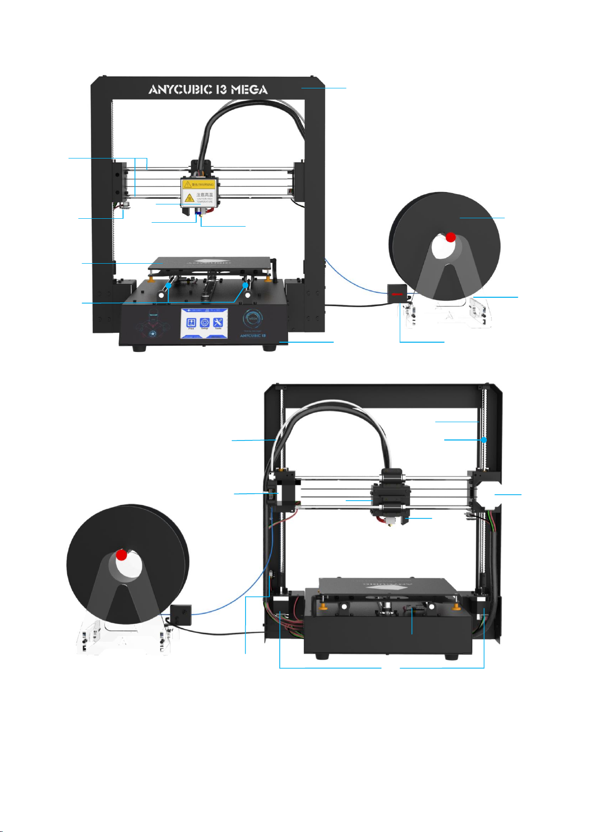
1. Product Overview
⑶
⑺
⑴
⑵
⑷
⑸
⑾
⑽
⑿
⑻
⑼
⑹
⒁
⒂
⒀
⒃
⒆
⒅
⒄
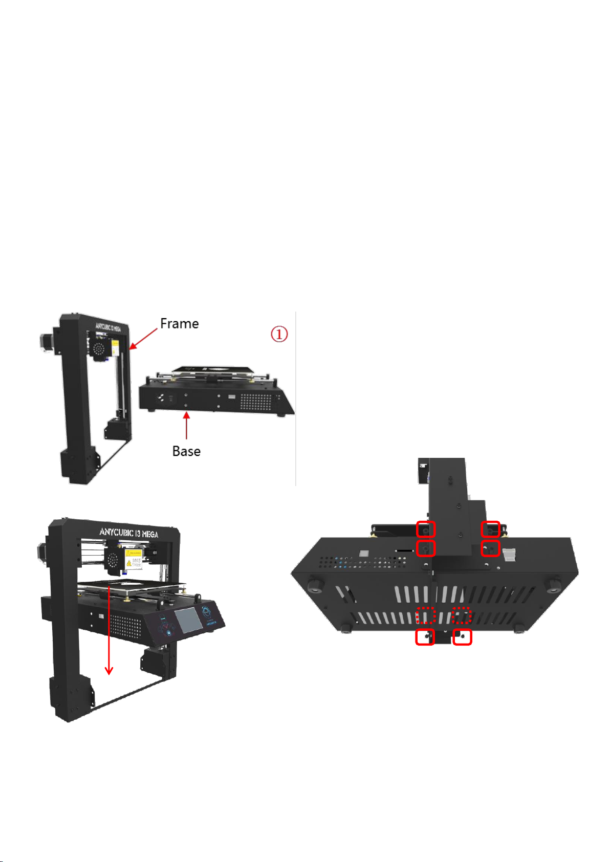
⑴Frame ⑵Base ⑶Print head ⑷Z probe ⑸Nozzle ⑹X smooth rods ⑺X end stop
⑻Print platform ⑼Y smooth rods ⑽Filament sensor ⑾Spool holder ⑿Filament spool
⒀Extruder ⒁Z smooth rods ⒂Z lead screw ⒃X motor ⒄Z end stop ⒅Z motors ⒆Y
end stop ⒇ Model cooling fan (21) Hotend cooling fan (22) Teflon tubing
⒇
(21)
(22)
2
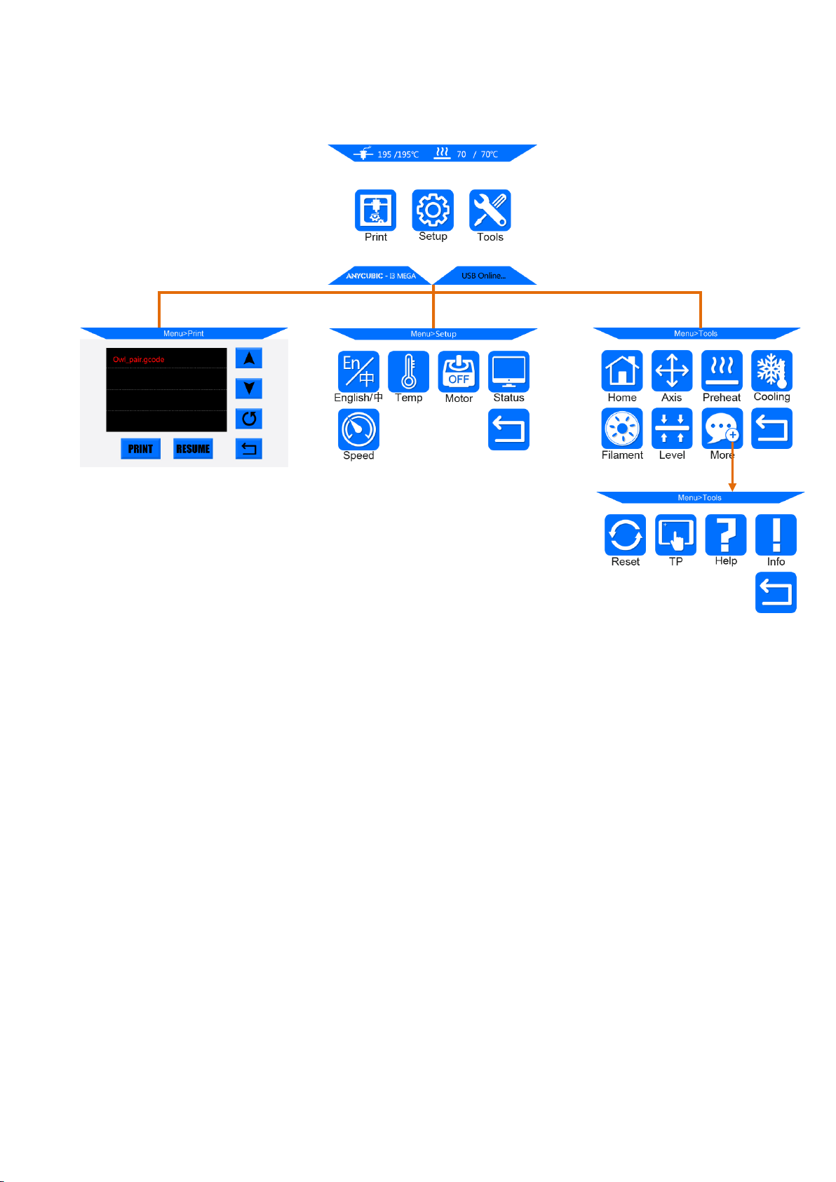
Home menu
Print: enter the print menu
Setup: enter the setup menu
Tools: enter the tools menu
(Other information: ①nozzle temperature ②heated bed temperature ③printer status)
Print
Print: print the selected files in SD card
Resume: Resume from outage (only valid for offline print)
(Other information: ①Page up and down ②Refresh ③Return to the home menu)
Setup
En/中: Language selection between English and Chinese
Temp: Enter the menu to adjust ① E0 (hotend) Temp (170-260°C) ②Bed Temp (0-120°C)
Menu Directory
Home Menu
Print
Tools
Setup

3
Motor: Disable all motors (only valid when no print job)
Status: Enter the sub-menu with Print/Pause/Resume icon (only valid for offline print)
(Other information: ①Files ②Print Rate ③Time ④Progress ⑤E0 Temp ⑥Bed Temp ⑦
coordinates for X/Y/Z axis ⑧Return to previous menu)
Speed: Enter the menu to adjust ①Fan speed (0-100) ②Print Rate (50-999)
Return: Return to Home Menu
Tools
Home: ①Home X ②Home Y ③Home Z ④Home All ⑤Return (only valid when no print job)
Axis: ① Home all axis ②Move X/Y/Z axis by 0.1/1/10 ③Choose the travel speed
Low/Medium/High (only valid when no print job)
Preheat: ①Preheat PLA ②Preheat ABS (only valid when no print job)
(Other information: ①E0 Temp ②Bed Temp)
Cooling: Cut off the power of hotend and heated bed (only valid when no print job)
Filament: ①Filament In ②Filament Remove ③ Stop (will automatically heating to 200°C for
filament in or remove) (only valid when on print job)
Reset: Popup window to decide if reboot the mainboard
More: Enter the next page of Tools sub-menu
TP: Touch panel alignment(click on the cue points)
Help: Basic description of the Menu
Info: Information about the product
Return: Return to Home Menu
4
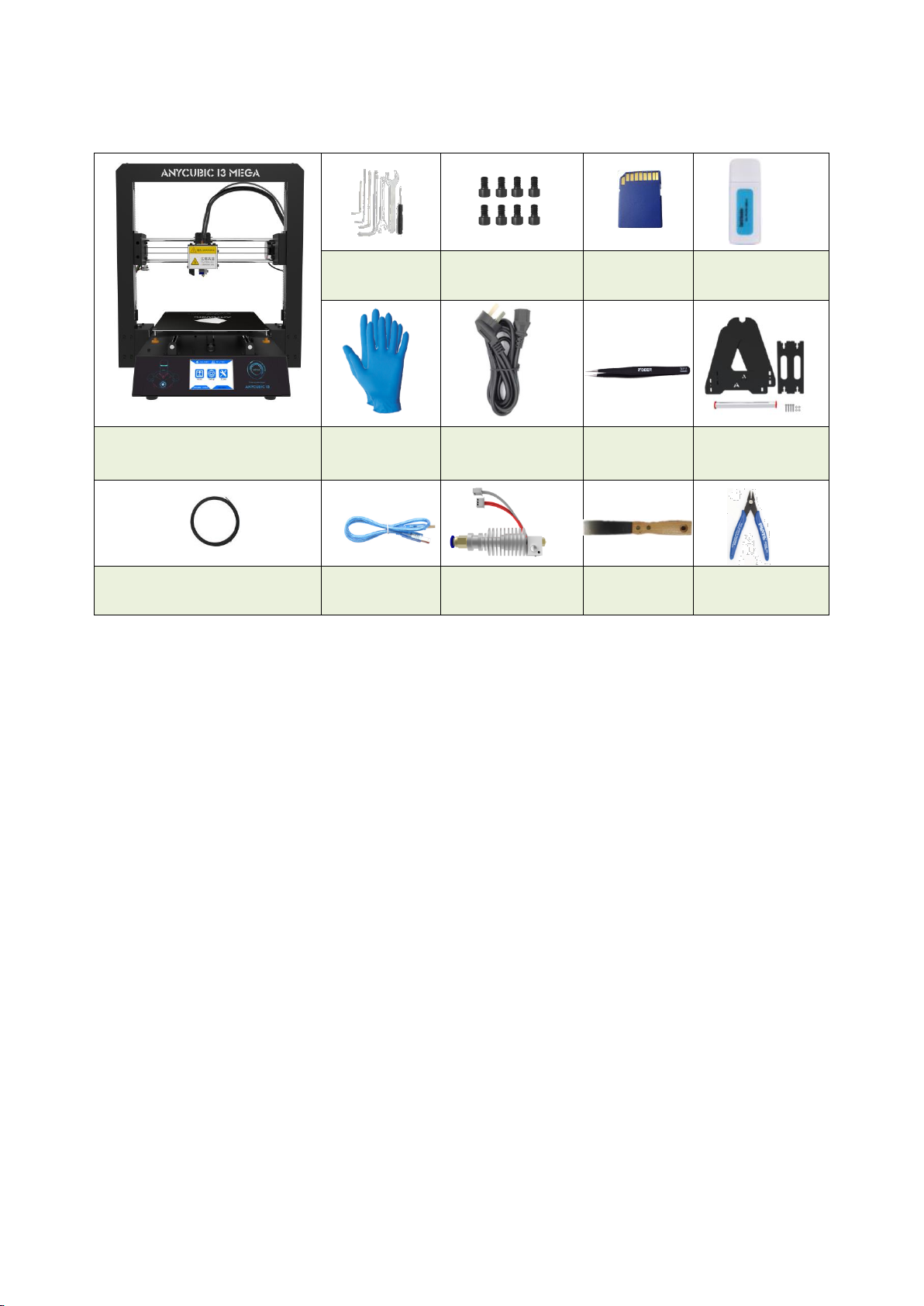
2. Part list
Tool pack
Screws(M5*8)
SD card
SD Card reader
ANYCUBIC i3 MEGA
Gloves
Power cord
Tweezer
Spool holder
Test filament (Random)
USB cable
Backup hotend
Scraper
Plier
5
3. Assembly instruction
1. Unpack and take out the printer and accessories.
The smooth rods and lead screw may be greased in factory, so please wear gloves.
2. Find 8 pieces of M5*8mm hex cap screws and the corresponding screw driver.
Follow ① ② ③ in Fig. 1. Carefully lift the base to fit into the frame and then fix them by
the M5*8mm hex cap screws. The screw locations are pointed with red squares in ③.
The screws can be installed in a diagonal order and can be tightened after all screws
inserted in place.
Figure 1
②
③
6
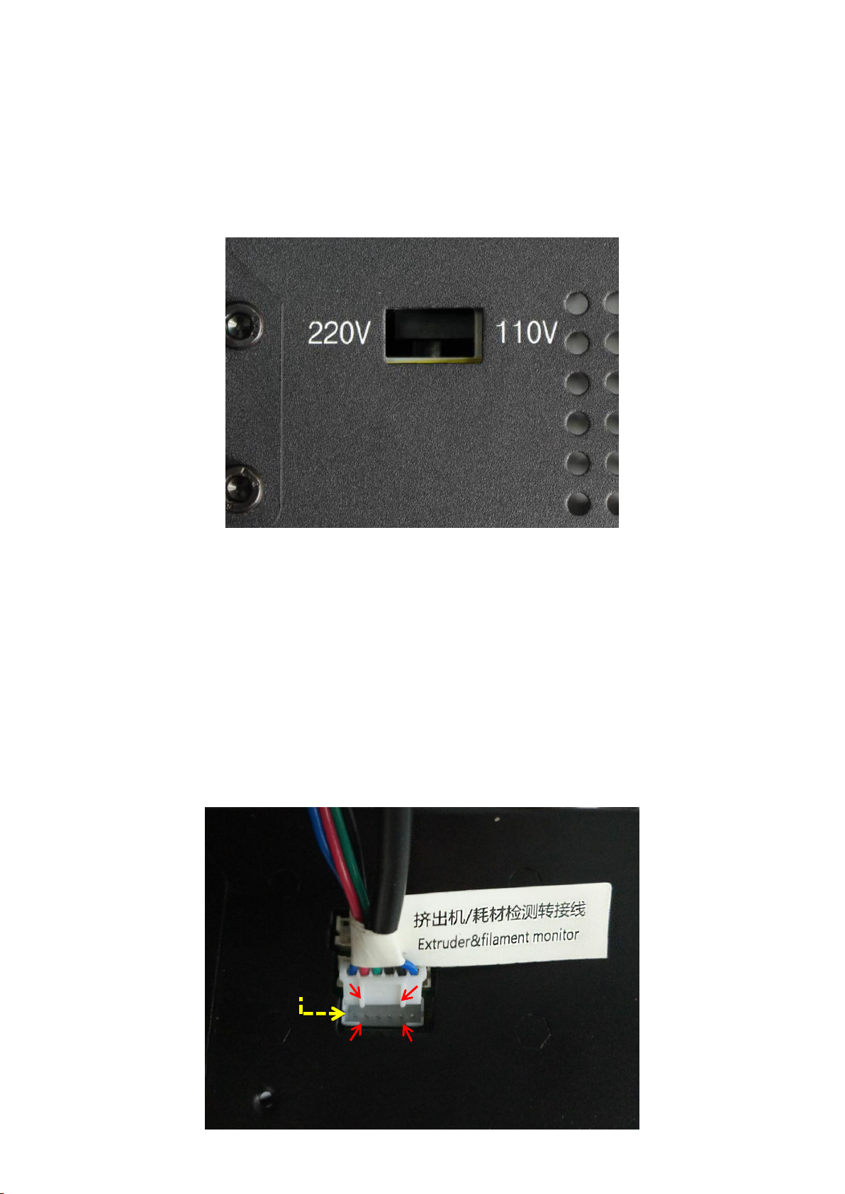
3. Wiring
(1) Fig.2, customers are required to select the correct voltage mode according to their local
voltage ratings (110V/220V). Please notice that the switch is inside the bottom left of the
base and 220V is default. A hex screw driver can be used to move the switch inside.
(2) There are 3 ports at the bottom right of the base, and accordingly there are 3 cable
connectors. Firstly, in Fig. 3, insert the cable connector labeled “Extruder&filament
monitor”(6 pins) to the lower port.
Pay close attention to the up and down side of the connector, and make sure the
connector is well inserted in place, and no pins bent. WRONG or loose connection would
lead to malfunction of the machine, the same for the rest of other two connectors.
Choose the voltage ratings
(Figure 3)
(Figure 2)
Lower port
Gap
Convex line

7
(3) Fig.4, insert “Hotend” connector to the middle port (14 pins).
(4) Fig.5, insert “X/Z motors&endstops” connector to the upper port (16 pins).
(Figure 4) (Figure 5)
(5) Fig. 6, customers may notice there is a piece of zip tie attached just below the plastic ring
of the quick connector. Do not cut it off. Only cut this zip tie when swapping or repairing
a malfunction hotend, because it needs to push down the plastic ring and pull out the
Teflon tubing.
4. Spool holder and filament sensor
(1) As shown in Fig. 7, assemble the spool holder and tighten 4 pairs of screw and nuts at
the lower corner. (The color and shape of the spool holder might be slightly different from this
pircture)
Convex line
Middle port
Gap
Upper port
Gap
Convex line
(Figure 6)
Plastic ring
Zip tie
Do not cut
 Loading...