


Pipe Hangers & Supports
www.anvilintl.com
MARCH 2016
For the most current product/pricing information on Anvil products, please visit our website at www.anvilintl.com

B U I L D I N G C O N N E C T I O N S T H AT L A S T
For over 160 years, Anvil has worked diligently to
build a strong, vibrant tradition of making connections — pipe to pipe and people to people.
We pride ourselves in providing the finest-quality pipe products and
services with integrity and dedication to superior customer service at all levels.
We provide expertise and product solutions for a wide range of applications, from plumbing, mechanical, HVAC, industrial and fire protection to mining, oil and gas. Our comprehensive line of products includes: grooved pipe
couplings, grooved and plain-end fittings, valves, cast and malleable iron fittings, forged steel fittings, steel pipe nipples and couplings, pipe hangers and supports, channel and strut fittings, mining and oil field fittings, along with much more.
As an additional benefit to our customers, Anvil offers a complete and comprehensive Design Services Analysis for mechanical equipment rooms, to help you determine the most effective and cost-efficient piping solutions.
Anvil is a proud member of the United States Green Building Council (USGBC).
Go to the Anvil website to obtain manufacturer recycled certificates and other
Green information.
At Anvil, we believe that responsive and accessible customer support is what makes the difference between simply delivering products —
and delivering solutions.

Pipe Hangers
and Supports
Manufacturing Excellence
Anvil Pipe Hangers and Supports are manufactured in three primary U.S. locations: North Kingstown, Rhode Island; Henderson, Tennessee and Columbia, Pennsylvania, each with its own unique capabilities.
At 150,000 square feet, our Pipe Support design and fabrication facility in North Kingstown, Rhode Island is the industry leader in the Engineered Hanger Market for experience and in house manufacturing capability. Our equipment can accommodate any project since we have the capability to machine, saw and flame cut up to 3" thick carbon and alloy steel and plasma cut stainless steel.
We thread rod through 4" in diameter and we hot form small to large diameter clamps. Our facility also has complete in house blasting and painting capability and we perform complete in house Non-Destructive Examination including Liquid Penetrant, Ultrasonic and Magnetic Particle examination. This expertise is supported by our total quality programs including our ASME “NPT” Nuclear Certificate of Authorization, “NS” Certificate of Authorization and, ISO 9001.
Our manufacturing facility in Henderson, Tennessee has over 175,000 square feet of manufacturing capability dedicated to producing a complete line of commercial, light industrial and industrial Pipe Hangers and Supports. These include clamps, braces, inserts, rods and attachments, slides and guides to exacting industry standards and certified to ISO 9001 quality. The products manufactured in Henderson are designed for use in a wide variety of rigid Pipe Hanger or Support applications, in markets including fire protection, electrical, water and waste water treatment, petrochemical, seismic, industrial and commercial. Special fabrication is available from our Henderson facility as well.
At our Columbia, Pennsylvania Foundry, where we manufacture malleable fittings, cast iron fittings and our Gruvlok® products, we also manufacture our malleable and ductile iron Hanger Products such as beam clamps, numerous types of pipe clamps, concrete inserts, ceiling flanges and different types of rod attachments. With over 600,000 square feet of manufacturing floor space under roof, our foundry has an annual pouring capacity of 100,000 tons. Columbia is ISO 9001 certified and is a quality manufacturer of malleable, ductile and cast iron products. In addition to these three facilities Anvil also has Hanger fabrication facilities in Houston, Texas to service the Gulf Coast Engineered Hanger requirements.
Customer Service
With four key stocking locations throughout North America, you can count on getting all of the product you need - when you need it. When you have installation questions our solid customer service personnel are there to answer all of you questions, backed by our designers or engineers we are there for you - on site if needed.
Custom Engineering Options
In addition to its full range of high-quality hangers, Anvil offers a number of custom options to meet any special project requirements you may have.
Engineered Hangers Product Line
•Variable Springs
•Constant Supports
•Hydraulic Snubbers
•Vibration Sway Braces
•Sway Struts
We also provide:
•Special Fabrication/ Miscellaneous Structural/ Steel Fabrication
•Special Design Products Per Customer Specifications
•Domestic Manufactured Product Line
Design Services
Either on or off-site, Anvil Design Services helps you maximize the efficiency of your pipe support systems.
These services include:
•Pipe Hanger Design & Engineering
•Computer-Aided Drafting
•System Analysis
•Pipe Stress Analysis
•Product Qualification Testing (environmental static and cycling loads, flow and leak)
•Field Services
•Supervision of Client Design Personnel
•Non-destructive Examination
PH-1.14


 TABLE OF CONTENTS
General Notes through Concrete Inserts & Attachments
General Notes |
|
Socket Clamps |
Standard Materials...................................................................................................... |
16 |
Fig. 595 & Fig. 594 Socket Clamp for Ductile Iron or Cast Iron Pipe....59 |
Standard Galvanizing Practice...................................................................... |
17 - 18 |
Fig. 600 & Fig. 599 Socket Clamp for Ductile Iron or Cast Iron Pipe..60 |
Copper Tubing Hangers |
|
Fig. CT-69 Adjustable Swivel Ring..................................................................... |
20 |
Fig. CT-65 Light Duty Adjustable Clevis.......................................................... |
21 |
Fig. CT-128R Rod Threaded Ceiling Flange..................................................... |
22 |
Fig. CT-138R Extension Split Tubing Clamp.................................................... |
22 |
Fig. 69F Adjustable Swivel Ring, Felt Lined.................................................... |
23 |
Fig. 67F Copper Tube Felt Lined Hanger......................................................... |
24 |
Fig. CT-121 Copper Tubing Riser Clamp............................................................ |
25 |
Fig. CT-255 Copper Tubing Alignment Guide..................................... |
26 - 27 |
Stainless Steel Hangers |
|
Fig. 137SS Standard U-Bolt...................................................................................... |
28 |
Fig. 260SS Adjustable Clevis Hanger................................................................ |
29 |
Fig. 261SS Extension Pipe or Riser Clamp....................................................... |
30 |
Fig. 590SS Adjustable Clevis for Ductile or Cast Iron Pipe.................... |
31 |
CPVC Pipe Hangers |
|
Fig. 185 One Hole Pipe Strap.................................................................................. |
32 |
Fig. 186 Two Hole Pipe Strap.................................................................................. |
33 |
Fig. 187 Two Hole 90˚ Side Mount Strap........................................................ |
34 |
Fig. 188 Two Hole Stand Off Strap..................................................................... |
35 |
Pipe Rings |
|
Fig. 108 Split Pipe Ring............................................................................................... |
36 |
Fig. 138R Extension Split Pipe Clamp................................................................. |
37 |
Fig. 104 Adjustable Swivel Ring, Split Ring Type......................................... |
38 |
Fig. 69 Adjustable Swivel Ring, Tapped per NFPA Standards............... |
39 |
Clevis |
|
Fig. 67 Pipe or Conduit Hanger............................................................................ |
40 |
Fig. 65 Light Duty Adjustable Clevis.................................................................. |
41 |
Fig. 260 Adjustable Clevis Hanger...................................................................... |
42 |
Fig. 260 ISS Clevis Hanger with Insulation Saddle System.......... |
43 - 45 |
Fig. 300 Adjustable Clevis for Insulated Lines............................................. |
46 |
Fig. 590 Adjustable Clevis for Ductile or Cast Iron Pipe........................ |
47 |
Steel Pipe Clamps |
|
Fig. 261 Extension Pipe or Riser Clamp............................................................ |
48 |
Fig. 40 Riser Clamp – Standard........................................................................... |
49 |
Fig. 103 Offset Pipe Clamp..................................................................................... |
50 |
Fig. 100 Extended Pipe Clamp.............................................................................. |
50 |
Fig. 212 Medium Pipe Clamp................................................................................... |
51 |
Fig. 212FP Seismic Bracing Clamp........................................................................ |
52 |
Fig. 216 Heavy Pipe Clamp....................................................................................... |
53 |
Fig. 295 Double Bolt Pipe Clamp........................................................................ |
54 |
Fig. 295A Alloy Double Bolt Pipe Clamp......................................................... |
55 |
Fig. 295H Heavy Duty Double Bolt Pipe Clamp......................................... |
56 |
Fig. 224 Alloy Steel Pipe Clamp........................................................................... |
57 |
Fig. 246 Heavy Duty Alloy Steel Pipe Clamp............................................... |
58 |
Beam Clamps |
|
Fig. 86 & Fig. 88 C-Clamp......................................................................................... |
61 |
Fig. 95 C-Clamp with Locknut............................................................................. |
62 |
Fig. 89 & 89X Retaining Clip................................................................................... |
63 |
Fig. 92 Universal C-Type Clamp (Standard Throat)................................... |
64 |
Fig. 93 Universal C-Type Clamp (Wide Throat)........................................... |
65 |
Fig. 94 Wide Throat Top Beam C-Clamp....................................................... |
66 |
Fig. 227 Top Beam Clamp........................................................................................ |
67 |
Fig. 217 Adjustable Side Beam Clamp.............................................................. |
68 |
Fig. 14 Adjustable Side Beam Clamp................................................................. |
68 |
Fig. 133 Standard Duty Beam Clamp................................................................. |
69 |
Fig. 134 Heavy Duty Beam Clamp....................................................................... |
69 |
Fig. 218 Malleable Beam Clamp without Extension Piece.................... |
70 |
Fig. 228 Universal Forged Steel (UFS) Beam Clamp................................... |
71 |
Fig. 292 & Fig. 292L Universal Forged Steel (UFS) Beam Clamp........... |
72 |
Structural Attachments |
|
Fig. 55 & Fig. 55L Structural Welding Lug........................................................ |
73 |
Fig. 54 Two Hole Welding Beam Lug................................................................. |
74 |
Fig. 66 Welded Beam Attachment..................................................................... |
75 |
Fig. 60 Steel Washer Plate....................................................................................... |
76 |
Fig. 112 Brace Fitting Complete............................................................................. |
77 |
Fig. 113 Brace Fitting (Pipe End Only).................................................................. |
77 |
Brackets |
|
Fig. 202 Iron Side Beam Bracket........................................................................... |
78 |
Fig. 206 Steel Side Beam Bracket....................................................................... |
79 |
Fig. 207 Threaded Steel Side Beam Bracket................................................. |
79 |
Fig. 194 Light Welded Steel Bracket................................................................. |
80 |
Fig. 195 Medium Welded Steel Bracket........................................................... |
81 |
Fig. 199 Heavy Welded Steel Bracket............................................................... |
82 |
Ceiling Plates & Ceiling Flanges |
|
Fig. 395 Cast Iron Ceiling Plate.............................................................................. |
83 |
Fig. 127 Plastic Ceiling Plate.................................................................................. |
83 |
Fig. 128R Rod Threaded Ceiling Flange............................................................ |
84 |
Fig. 153 Pipe Hanger Flange.................................................................................... |
85 |
Concrete Inserts & Attachments |
|
Fig. 152 Screw Concrete Insert............................................................................. |
86 |
Fig. 282 Universal Concrete Insert..................................................................... |
87 |
Fig. 281 Wedge Type Concrete Insert.............................................................. |
88 |
Fig. 285 Light Weight Concrete Insert............................................................. |
89 |
Fig. 286 Iron Cross...................................................................................................... |
90 |
Fig. 284 Metal Deck Hanger................................................................................... |
91 |
Fig. 47 Concrete Single Lug Plate........................................................................ |
92 |
Fig. 49 Concrete Clevis Plate................................................................................. |
93 |
Fig. 52 Concrete Rod Attachment Plate......................................................... |
94 |
4 |
www.anvilintl.com |
PH-3.16

TABLE OF CONTENTS 


Hanger Rods through Constant Supports
Hanger Rods |
|
Fig. 142 Coach Screw Rods..................................................................................... |
95 |
Fig. 146 Continuous Threaded Rod................................................................... |
95 |
Fig. 140 Machine Threaded Rods (Right-Hand Threads)....................... |
96 |
Fig. 253 Machine Threaded Rods (Right and Left-Hand Threads).... 96 |
|
Fig. 248 & Fig. 248L Eye Rod (Not Welded).................................................. |
96 |
Fig. 278 & Fig. 278L Eye Rod (Welded)............................................................. |
97 |
Fig. 248X Linked Eye Rods (Not Welded)...................................................... |
97 |
Fig. 278X Linked Eye Rods (Welded)................................................................. |
97 |
Fig. 148 Rod with Eye End....................................................................................... |
98 |
Rod Attachments |
|
Fig. 135, Fig. 135E & Fig. 135R Rod Coupling..................................................... |
99 |
Fig. 136 & Fig. 136R Rod Coupling........................................................................ |
99 |
Fig. 114 Turnbuckle Adjuster................................................................................ |
100 |
Fig. 110R Socket, Rod Threaded......................................................................... |
100 |
Fig. 157 Extension Piece........................................................................................... |
101 |
Fig. 290 & Fig. 290L Weldless Eye Nut........................................................... |
101 |
Fig. 299 Forged Steel Clevis................................................................................. |
102 |
Fig. 233 Turnbuckle.................................................................................................... |
103 |
Fig. 230 Turnbuckle................................................................................................... |
103 |
Bolts, Nuts, Pins & U-Bolts |
|
Fig. 291 Clevis Pin with Cotters.......................................................................... |
104 |
Machine Bolts & Hexagon Nuts......................................................................... |
105 |
Fig. 137, Fig. 137S Standard & Special U-Bolts.............................................. |
106 |
Fig. 137C Plastic Coated U-Bolt........................................................................... |
107 |
Fig. 120 Light Weight U-Bolt................................................................................ |
107 |
Straps |
|
Fig. 126 One-Hole Clamp.................................................................................... |
108 |
Fig. 262 Strap Short.................................................................................................. |
108 |
Fig. 243 & 244 Pipe Strap....................................................................................... |
109 |
Pipe Supports |
|
Fig. 62 Pipe Stanchion.............................................................................................. |
110 |
Fig. 63 Pipe Stanchion................................................................................................ |
111 |
Fig. 192 Adjustable Pipe Saddle........................................................................... |
112 |
Fig. 191 Adjustable Pipe Saddle with U-Bolt................................................. |
112 |
Fig. 258 Pipe Saddle Support................................................................................ |
113 |
Fig. 264 Adjustable Pipe Saddle Support....................................................... |
114 |
Fig. 265 Adjustable Pipe Saddle Support with U-Bolt............................ |
115 |
Fig. 259 Pipe Saddle Support with U-Bolt..................................................... |
116 |
Trapeze |
|
Fig. 46 Universal Trapeze Assembly.................................................................. |
117 |
Fig. 45 Channel Assembly....................................................................................... |
118 |
Fig. 50 Equal Leg Angle for Trapeze Assembly............................................ |
119 |
Pipe Shields & Saddles |
|
Fig. 167 Insulated Protection Shield................................................................ |
120 |
Fig. 168 Rib-Lok Shield.............................................................................................. |
121 |
Fig. 160 to Fig. 166A Pipe Covering Protection Saddle................ |
122 - 125 |
Pipe Rolls |
|
Fig. 177 Adjustable Pipe Roll Support............................................................. |
126 |
Fig. 171 Single Pipe Roll............................................................................................ |
127 |
Fig. 178 Spring Cushion Hanger........................................................................... |
128 |
Fig. 181 Adjustable Steel Yoke Pipe Roll......................................................... |
129 |
Fig. 175 Roller Chair................................................................................................... |
130 |
Fig. 277 Pipe Roll and Base Plate......................................................................... |
131 |
Fig. 271 Pipe Roll Stand........................................................................................... |
132 |
Fig. 274, Fig. 274P & Fig. 275 Adjustable Pipe Roll Stand........................ |
133 |
Fig. 75LL Longitudinal & Lateral Roller........................................................... |
134 |
Fig. 76CP Non-Conductive Roller..................................................................... |
134 |
Pipe Guide & Slides |
|
Fig. 255 Pipe Alignment Guide................................................................. |
136 - 137 |
Fig. 256 Pipe Alignment Guide................................................................. |
138 - 139 |
Fig. 257 & Fig. 257A Structural Tee Slide Assembly...................... |
140 - 143 |
Fig. 436 & Fig. 436A Fabricated Tee Slide Assembly.................... |
140 - 143 |
Fig. 439 & Fig. 439A Structural "H" Slide Assembly........................ |
144 - 145 |
Fig. 432 Special Clamp............................................................................................. |
146 |
Fig. 212 Medium Pipe Clamp................................................................................ |
147 |
Sway Brace - Seismic |
|
Fig. 770 Q Brace Clamp.............................................................................. |
148 - 149 |
Fig. 776 Brace Clamp..................................................................................... |
150 - 151 |
Fig. 775 Lateral/Longitudinal Brace Clamp...................................... |
152 - 153 |
Fig. 778 Bar Joist and Beam Attachment (WF)................................. |
154 - 155 |
Fig. 772 Adjustable Steel Beam Attachment................................... |
156 - 158 |
Fig. 779 Multi-Connector Adapter................................................................... |
159 |
Fig. 773 Surge Restrainer........................................................................................ |
160 |
Fig. 777 Swivel Joint Connector - Rod Tap................................................... |
161 |
Fig. 771 Sway Brace Swivel Attachment.............................................. |
162 - 163 |
Spring Hangers |
|
Fig. 82, B-268, 98, Triple & Quadruple Springs............................... |
164 - 165 |
Spring Hanger Size & Series Selection................................................. |
166 - 167 |
Check List...................................................................................................................... |
168 |
Fig. B-268, Fig. C-268 Type A................................................................................ |
169 |
Fig. B-268, Fig. C-268 Type B & C....................................................................... |
170 |
Fig. B-268, Fig. C-268 Type D & E........................................................................ |
171 |
Fig. B-268, Fig. C-268 Type F................................................................................. |
172 |
Fig. B-268, Fig. C-268 Type G............................................................................... |
173 |
Fig. 82, Fig. C-82 Series Short Spring..................................................... |
174 - 175 |
Fig. 98, Fig. C-98 Series Double Spring................................................ |
176 - 177 |
Triple Spring, Triple Spring-CR Series.................................................. |
178 - 179 |
Quadruple Spring, Quadruple Spring-CR Series............................ |
180 - 181 |
Constant Supports |
|
Model R 80-V, C-80-V Vertical & 81-H, C-81-H Horizontal...... |
182 - 185 |
Total Travel & Selection Chart............................................................... |
186 - 189 |
Fig. 80-V Type A........................................................................................................ |
190 |
Fig. 80-V Type B........................................................................................................... |
191 |
Fig. 80-V Type C.......................................................................................................... |
192 |
Table of |
Contents |
|
|
General |
Notes |
|
|
Copper Tubing |
Hangers |
|
|
|
|
Stainless Steel |
Hangers |
|
|
CPVC |
Pipe Hangers |
|
|
|
|
Pipe |
Rings |
|
|
Clevis |
Hangers |
|
|
|
|
Steel Pipe |
Clamps |
|
|
|
|
Socket |
Clamps |
|
|
|
|
Beam |
Clamps |
|
|
|
|
Structural |
Attachments |
|
|
|
|
Brackets |
|
|
|
|
|
Ceiling Plates & Flanges |
|
|
|
|
|
Concrete Inserts |
& Attachments |
|
|
|
|
Hanger |
Rods |
|
|
|
|
Rod |
Attachments |
|
|
|
|
Bolts, Nuts, |
Pins & U-Bolts |
|
|
www.anvilintl.com |
5 |
PH-3.16


 TABLE OF CONTENTS
Constant Supports through Index
Fig. 80-V Type D......................................................................................................... |
193 |
Fig. 80-V Type E.......................................................................................................... |
194 |
Fig. 80-V Type F.......................................................................................................... |
195 |
Fig. 80-V Type G......................................................................................................... |
196 |
Fig. 80-V Type A, B & C Size 84-110.................................................................. |
197 |
Fig. 81-H Type A.......................................................................................................... |
198 |
Fig. 81-H Type B........................................................................................................... |
199 |
Fig. 81-H Type C........................................................................................................ |
200 |
Fig. 81-H Type D......................................................................................................... |
201 |
Fig. 81-H Type E.......................................................................................................... |
202 |
Fig. 81-H Type F Upthrust..................................................................................... |
203 |
Fig. 81-H Type A, B, C & E Size 84-110............................................................ |
204 |
Fig. 80-V and Fig. 81-H Weight Chart............................................................. |
205 |
Check List.................................................................................................................... |
206 |
Fig. 170 Horizontal Traveler.................................................................................. |
207 |
Vibration Control & Sway Brace |
|
Fig. 296, 301, C-296, C-301........................................................................ |
208 - 209 |
Fig. 297, 298, 302, 303.............................................................................................. |
210 |
Maximum Recommended Applied Torques.............................................. |
248 |
Beam Dimensions..................................................................................................... |
249 |
Anvil Compliances, Listings and Approvals........... |
250 - 255 |
Anvil Pipe Hanger & Support Services.................................... |
256 |
Anvil Terms of Sale and Conditions........................................... |
257 |
Index |
|
Subject Index.............................................................................................................. |
258 |
Numerical Index............................................................................................. |
259 - 261 |
Anvil reserves the right to make specification changes without notice. While every effort has been made to assure the accuracy of information contained in this catalog at the time of publication, we cannot accept responsibility for inaccuracies resulting from undetected errors or omissions.
The acceptability of galvanized coatings at temperatures above 450°F is at the discretion of the end user.
Rod load ratings shown in this catalog are based upon MSS-SP-58 (2002 and later).
Sway Strut Assembly
Fig. 211, C-211, 640, C-640 Sway Strut Assembly............................... |
211 |
- 212 |
Fig. 222, C-222 Mini-Sway Strut Assembly........................................ |
213 |
- 214 |
Check List...................................................................................................................... |
|
215 |
Snubbers
Fig. 3306, 3307 Hydraulic Snubber........................................................ |
216 - 219 |
Fig. 200, C-200, 201, C-201 Hydraulic Snubber.............................. |
220 - 223 |
Fig. 312 Tapered Pin.................................................................................................. |
224 |
Special Design Products
Fig. 38SD Half Clamp.............................................................................................. |
225 |
Fig. 53SD Welding Lug for L.R. Elbow............................................................ |
225 |
Fig. 71SD Double Roll Horizontal Traveler................................................... |
225 |
Fig. 72SD Dual Direction Horizontal Traveler............................................ |
226 |
Fig. 75SD Flat Roller with Saddle...................................................................... |
226 |
Fig. 76SD Fabricated Roller for Large Diameter Pipe............................. |
226 |
Fig. 40SD Riser Clamp............................................................................................ |
227 |
Fig. 41SD Non-Standard Three Bolt Pipe Clamp...................................... |
227 |
Fig. 42SD Non-Standard Two Bolt Pipe Clamp......................................... |
228 |
Application Assembly Examples........................................ |
229 - 236 |
Technical Data |
|
Pipe Hanger Specifications...................................................................... |
237 - 238 |
Master Format 3 Part Specification................................................................. |
239 |
Pipe Support Spacing................................................................................. |
240 - 241 |
Steel Pipe Data............................................................................................... |
242 - 243 |
Copper Tube Data.................................................................................................... |
243 |
Soil Pipe Data.............................................................................................................. |
244 |
AWWA Ductile Iron Pipe Data.......................................................................... |
244 |
PVC Plastic Pipe Data.............................................................................................. |
245 |
Thermal Expansion of Pipe Material.................................................. |
246 - 247 |
Threaded Rod Data................................................................................................. |
248 |
6 |
www.anvilintl.com |
PH-3.16

PICTORIAL TABLE OF CONTENTS 


Copper Tubing Hangers –– Pipe Rings
COPPER TUBING HANGERS
Fig. CT-69 |
Fig. CT-65 |
Fig. CT-138R |
Fig. 69F |
Fig. 67F |
Adjustable Swivel Ring |
Light Duty Adjustable Clevis |
Extension Split Tubing Clamp |
Adjustable Swivel Ring Felt Lined |
Copper Tube Felt Lined Hanger |
Size Range: 1/2" thru 4" |
Size Range: 1/2" thru 4" |
Size Range: 1/2" thru 2" |
Size Range: 1/2" thru 6" |
Size Range: 1/2" thru 6" |
Page 20 |
Page 21 |
Page 22 |
Page 23 |
Page 24 |
|
|
|
|
|
Fig. CT-255 |
Fig. CT-121 |
Fig. CT-128R |
Copper Tubing Alignment Guide |
Copper Tubing Riser Clamp |
Rod Threaded Ceiling Flange |
Size Range: 1" thru 4" |
Size Range: 1/2" thru 4" |
Size Range: 3/8" thru 1/2" |
Pages 26 - 27 |
Page 25 |
Page 22 |
STAINLESS STEEL HANGERS
Fig. 137SS |
Fig. 260SS |
Fig. 261SS |
Fig. 590SS |
Standard U-Bolt |
Adjustable Clevis Hanger |
Extension Pipe or Riser Clamp |
Adjustable Clevis for Ductile or C.I. Pipe |
Size Range: 1/2" thru 12" |
Size Range: 1/2" thru 12" |
Size Range: 1/2" thru 8" |
Size Range: 4" thru 12" |
Page 28 |
Page 29 |
Page 30 |
Page 31 |
CPVC PIPE HANGERS
|
Fig. 185 |
|
Fig. 186 |
|
Fig. 187 |
|
Fig. 188 |
|
|
|
|
||||
|
|
|
|
||||
|
One Hole Pipe Strap |
|
Two Hole Pipe Strap |
|
Two Hole 90˚ Side Mount Strap |
|
Two Hole Stand Off Strap |
|
Size Range: 3/4" thru 2" |
|
Size Range: 3/4" thru 2" |
|
Size Range: 3/4" thru 2" |
|
Size Range: 3/4" thru 2" |
|
Page 32 |
|
Page 33 |
|
Page 34 |
|
Page 35 |
|
|
|
|
|
|
|
|
PIPE RINGS
Fig. 108 |
Fig. 138R |
Fig. 104 |
|
Fig. 69 |
|
||||
|
||||
Split Pipe Ring |
Extension Split Pipe Clamp |
Adjustable Swivel Ring, Split Ring Type |
|
Adjustable Swivel Ring |
Size Range: 3/8" thru 8" |
Size Range: 3/8" thru 3" |
Size Range: 3/4" thru 8" |
|
Size Range: 1/2" thru 8" |
Page 36 |
Page 37 |
Page 38 |
|
Page 39 |
|
|
|
|
|
Table of |
Contents |
|
|
General |
Notes |
|
|
Copper Tubing |
Hangers |
|
|
|
|
Stainless Steel |
Hangers |
|
|
CPVC |
Pipe Hangers |
|
|
|
|
Pipe |
Rings |
|
|
Clevis |
Hangers |
|
|
|
|
Steel Pipe |
Clamps |
|
|
|
|
Socket |
Clamps |
|
|
|
|
Beam |
Clamps |
|
|
|
|
Structural |
Attachments |
|
|
|
|
Brackets |
|
|
|
|
|
Ceiling Plates & Flanges |
|
|
|
|
|
Concrete Inserts |
& Attachments |
|
|
|
|
Hanger |
Rods |
|
|
|
|
Rod |
Attachments |
|
|
|
|
Bolts, Nuts, |
Pins & U-Bolts |
|
|
www.anvilintl.com |
7 |
PH-1.14


 PICTORIAL TABLE OF CONTENTS
Clevis –– Steel Pipe Clamps
CLEVIS
Fig. 67 |
Fig. 65 |
|
Fig. 260 |
Pipe or Conduit Hanger |
Light Duty Adjustable Clevis |
|
Adjustable Clevis Hanger |
Size Range: 1/2" thru 6" |
Size Range: 3/8" thru 4" |
|
Size Range: 1/2" thru 30" |
Page 40 |
Page 41 |
|
Page 42 |
Fig. 260 ISS |
Fig. 300 |
Fig. 590 |
Clevis Hanger with Insulation Saddle System |
Adjustable Clevis for Insulated Lines |
Adjustable Clevis for Ductile or Cast Iron |
Size Range: 2" thru 16" |
Size Range: 3/4" thru 12" |
Size Range: 3" thru 24" |
Pages 43 - 45 |
Page 46 |
Page 47 |
STEEL PIPE CLAMPS
Fig. 261 |
Fig. 40 |
Fig. 103 |
Fig. 100 |
Extension Pipe or Riser Clamp |
Riser Clamp Standard |
Offset Pipe Clamp |
Extended Pipe Clamp |
Size Range: 3/4" thru 24" |
Size Range: 2" thru 24" |
Size Range: 3/4" thru 8" |
Size Range: 1/2" thru 8" |
Page 48 |
Page 49 |
Page 50 |
Page 50 |
|
|
|
|
|
|
|
|
Fig. 212 |
Fig. 212FP |
Fig. 216 |
Fig. 295 |
Medium Pipe Clamp |
Seismic Bracing Clamp |
Heavy Pipe Clamp |
Double Bolt Pipe Clamp |
Size Range: 1/2" thru 30" |
Size Range: 21/2" thru 12" |
Size Range: 3" thru 42" |
Size Range: 3/4" thru 36" |
Page 51 |
Page 52 |
Page 53 |
Page 54 |
|
Fig. 295A |
Fig. 295H |
Fig. 224 |
Fig. 246 |
|
Alloy Double Bolt Pipe Clamp |
Heavy Duty Double Bolt Pipe Clamp |
Alloy Steel Pipe Clamp |
Heavy Duty Alloy Steel Pipe Clamp |
|
Size Range: 11/2" thru 24" |
Size Range: 6" thru 36" |
Size Range: 4" thru 16" |
Size Range: 10" thru 24" |
|
Page 55 |
Page 56 |
Page 57 |
Page 58 |
8 |
|
|
www.anvilintl.com |
|
PH-3.16
PICTORIAL TABLE OF CONTENTS 


Socket Clamps –– Structural Attachments
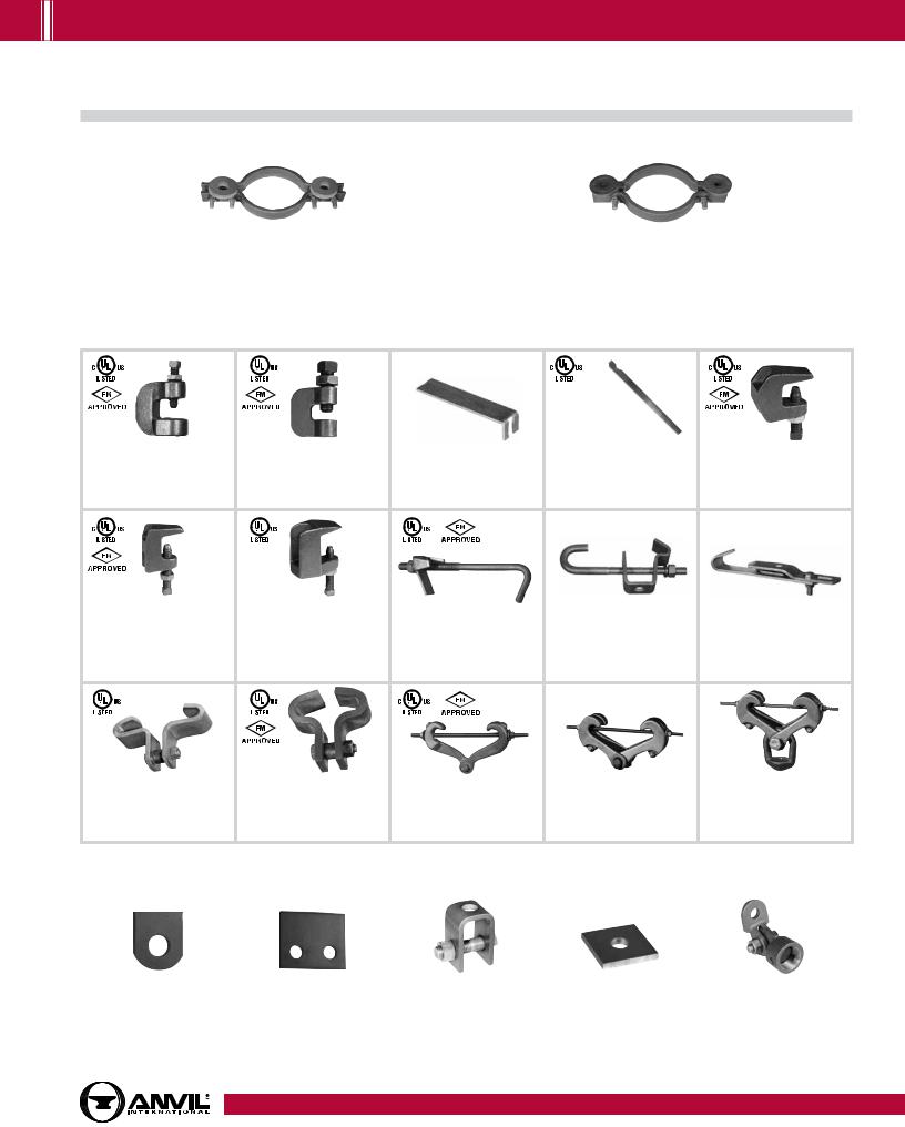
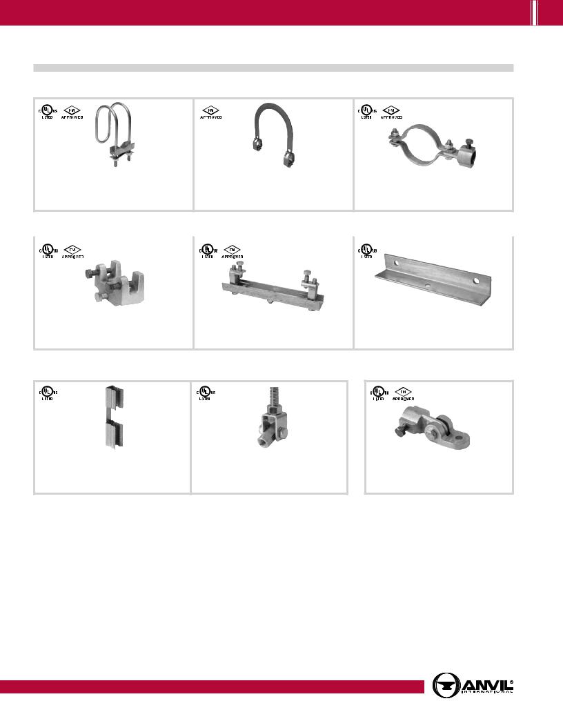
SOCKET CLAMPS
Fig. 595 & 594 |
Fig. 600 & 599 |
Socket Clamp for Ductile Iron or Cast Iron Pipe & Socket Clamp Washer |
Socket Clamp for Ductile Iron or Cast Iron Pipe & Socket Clamp Washer |
Size Range: 4" thru 24" pipe |
Size Range: 3" thru 24" pipe |
Page 59 |
Page 60 |
|
|
BEAM CLAMPS
|
|
Fig. 86 & 88 |
|
Fig. 95 |
Fig. 89 |
|
Fig. 89X |
|
|
Fig. 92 |
C-Clamp with Set Screw and Lock Nut |
|
C-Clamp with Locknut |
Retaining Clip |
|
Retaining Clip |
Universal C-Type Clamp Standard Throat |
||||
|
|
Size Range: 3/8" thru 3/4" |
|
Size Range: 3/8" and 1/2" |
Size Range: 3/8" thru 1/2" |
|
Size Range: 3/8" thru 3/4" |
|
|
Size Range: 3/8" and 1/2" |
|
|
Page 61 |
|
Page 62 |
Page 63 |
|
Page 63 |
|
|
Page 64 |
|
|
Fig. 93 |
Fig. 94 |
Fig. 227 |
Fig. 14 |
Fig. 217 |
|
|
Universal C-Type Clamp |
Wide Throat |
Top Beam Clamp |
Adjustable Side Beam Clamp |
Adjustable Side Beam Clamp |
|
|
Wide Throat |
Top Beam C-Clamp |
Page 67 |
Size Range: 3/8" thru 5/8" |
Size Range: 3" thru 75/8" |
|
|
Size Range: 3/8" and 1/2" |
Size Range: 5/8" and 3/4" |
|
Page 68 |
Page 68 |
|
|
Page 65 |
Page 66 |
|
|
|
|
|
|
|
|
|
|
|
|
|
|
|
|
|
Fig. 133 |
Fig. 134 |
Fig. 218 |
Fig. 228 |
Fig. 292 & 292L |
Standard Duty Beam Clamp |
Heavy Duty Beam Clamp |
Malleable Beam Clamp without |
Universal Forged Steel Beam Clamp |
Universal Forged Steel |
Size Range: 4" thru 12" |
Size Range: 4" thru 12" |
Extension Piece |
Page 71 |
Beam Clamp with Weldless Eye Nut |
Page 69 |
Page 69 |
Page 70 |
|
Page 72 |
STRUCTURAL ATTACHMENTS
Fig. 55 & 55L |
Fig. 54 |
Fig. 66 |
Fig. 60 |
Fig. 112 & 113 |
Structural Welding Lug |
Two-Hole Welding Beam Lug |
Welding Beam Attachment |
Steel Washer Plate |
Brace Fitting Complete |
Size Range (55): 1/2" thru 33/4" |
Size Range: 1/2" thru 21/4" |
Size Range: 3/8" thru 31/2" |
Size Range: 3/8" thru 33/4" |
Size Range: 1" and 11/4" |
Size Range (55L): 1/2" thru 2" |
Page 74 |
Page 75 |
Page 76 |
Page 77 |
Page 73 |
|
|
|
|
Table of |
Contents |
|
|
General |
Notes |
|
|
Copper Tubing |
Hangers |
|
|
|
|
Stainless Steel |
Hangers |
|
|
CPVC |
Pipe Hangers |
|
|
|
|
Pipe |
Rings |
|
|
Clevis |
Hangers |
|
|
|
|
Steel Pipe |
Clamps |
|
|
|
|
Socket |
Clamps |
|
|
|
|
Beam |
Clamps |
|
|
|
|
Structural |
Attachments |
|
|
|
|
Brackets |
|
|
|
|
|
Ceiling Plates & Flanges |
|
|
|
|
|
Concrete Inserts |
& Attachments |
|
|
|
|
Hanger |
Rods |
|
|
|
|
Rod |
Attachments |
|
|
|
|
Bolts, Nuts, |
Pins & U-Bolts |
|
|
www.anvilintl.com |
9 |
PH-3.16


 PICTORIAL TABLE OF CONTENTS
Brackets –– Concrete Inserts & Attachments
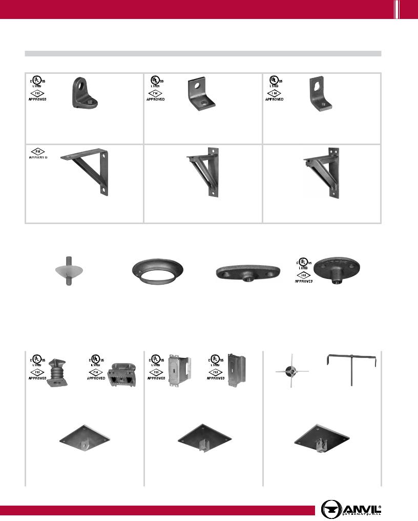
BRACKETS
|
Fig. 202 |
|
Fig. 206 |
|
Fig. 207 |
|
Iron Side Beam Bracket |
|
Steel Side Beam Bracket |
|
Threaded Steel Side Beam Bracket |
|
Size Range: 3/8" thru 5/8" |
|
Size Range: 3/8" thru 5/8" |
|
Size Range: 3/8" and 1/2" |
|
Page 78 |
|
Page 79 |
|
Page 79 |
Fig. 194 |
Fig. 195 |
Fig. 199 |
Light Welded Steel Bracket |
Medium Welded Steel Bracket |
Heavy Welded Steel Bracket |
Page 80 |
Page 81 |
Page 82 |
CEILING PLATES
Fig. 127 |
Fig. 395 |
Fig. 128R |
|
Fig. 153 |
|
||||
|
||||
Plastic Ceiling Plate |
Cast Iron Ceiling Plate |
Rod Threaded, Ceiling Flange |
|
Pipe Hanger Flange |
Size Range: 3/8" and 1/2" |
Size Range: 1/2" thru 8" |
Size Range: 3/8" and 1/2" |
|
Size Range: 3/8" thru 3/4" |
Page 83 |
Page 83 |
Page 84 |
|
Page 85 |
|
|
|
|
|
CONCRETE INSERTS & ATTACHMENTS
|
Fig. 152 |
|
Fig. 282 |
|
Fig. 281 |
|
Fig. 285 |
Fig. 286 |
Fig. 284 |
|
|
|
|
||||||
|
|
|
|
||||||
|
Screw Concrete Insert |
Universal Concrete Insert |
Wedge Type Conrete Insert |
Light Weight Concrete Insert |
Iron Cross |
Metal Deck Hanger |
|||
Size Range: 3/8" thru 7/8" |
Size Range: 3/8" thru 7/8" |
Size Range: 1/4" thru 7/8" |
Size Range: 1/4" thru 5/8" |
Size Range: 3/4" thru 11/2" |
Size Range: 3/8" thru 3/4" |
||||
|
Page 86 |
|
Page 87 |
|
Page 88 |
|
Page 89 |
Page 90 |
Page 91 |
|
|
|
|
|
|
|
|
|
|
|
Fig. 47 |
Fig. 49 |
Fig. 52 |
|
Concrete Single Lug Plate |
Concrete Clevis Plate |
Concrete Rod Attachment Plate |
|
Size Range: 1/2" thru 2" |
Size Range: 3/8" thru 13/4" |
Size Range: 3/8" thru 11/4" |
|
Page 92 |
Page 93 |
Page 94 |
|
|
|
|
10 |
|
|
www.anvilintl.com |
PH-3.16
PICTORIAL TABLE OF CONTENTS 


Hanger Rods & Attachments –– Straps
HANGER RODS & ATTACHMENTS
Fig. 142 |
Fig. 146 |
Fig. 140 & 253 |
Coach Screw Rods Machine Threaded on Opposite End |
Continuous Thread |
Machine Threaded Rods Threaded on Both Ends |
Size Range: 3/8" thru 1/2" |
Size Range: 1/4" thru 11/2" |
Size Range: 3/8" thru 5" |
Page 95 |
Page 95 |
Page 96 |
|
|
|
|
|
Fig. 136: |
|
|
Fig. 136R: |
Fig. 248 |
Fig. 278 |
Fig. 248X |
Fig. 278X |
Fig. 148 |
Fig. 135 & 135E Fig. 136 & 136R |
Fig. 114 |
|
Eye Rod Not Welded |
Eye Rod Welded |
Linked Eye Rods |
Linked Eye Rods Welded |
Rod with Eye End |
Straight Rod Coupling Straight Rod Coupling |
Turnbuckle Adjuster |
|
Size Range: |
Size Range: |
Size Range: |
Size Range: |
Size Range: |
Size Range: |
Size Range: |
Size Range: |
3/8" thru 21/2" |
3/8" thru 21/2" |
3/8" thru 21/2" |
3/8" thru 21/2" |
23/4" thru 5" |
1/4" thru 1" |
1/4" thru 1" |
1/4" thru 3/4" |
Page 96 |
Page 97 |
Page 97 |
Page 97 |
Page 98 |
Page 99 |
Page 99 |
Page 100 |
|
|
|
|
|
|
|
|
|
|
Fig. 110R |
Fig. 157 |
Fig. 290 |
Fig. 299 |
Fig. 230 |
Fig. 233 |
Fig. 291 |
Machine Bolts and |
Socket, Rod Threaded |
Extension Piece |
Weldless Eye Nut |
Forged Steel Clevis |
Turnbuckle |
Turnbuckle |
Clevis Pin with Cotters |
Hex Nuts |
|
|
Size Range: |
Size Range: |
Size Range: |
Size Range: |
Size Range: |
Size Range: |
Size Range: |
Page 105 |
|
1/4" thru 7/8" |
3/8" thru 7/8" |
3/8" thru 21/2" |
3/8" thru 4" |
3/8" thru 21/2" |
11/4" thru 5" |
1/2" thru 4" |
|
|
Page 100 |
Page 101 |
Page 101 |
Page 102 |
Page 103 |
Page 103 |
Page 104 |
|
Table of |
Contents |
|
|
General |
Notes |
|
|
Copper Tubing |
Hangers |
|
|
|
|
Stainless Steel |
Hangers |
|
|
CPVC |
Pipe Hangers |
|
|
|
|
Pipe |
Rings |
|
|
Clevis |
Hangers |
|
|
|
|
Steel Pipe |
Clamps |
|
|
|
|
Socket |
Clamps |
|
|
|
|
Beam |
Clamps |
|
|
|
|
Structural |
Attachments |
|
|
|
|
Brackets |
|
|
|
U-BOLTS |
STRAPS |
Fig. 137 & 137S |
Fig. 137C |
Fig. 120 |
|
Fig. 262 |
Fig. 126 |
Fig. 243 |
Fig. 244 |
|
Strap Short |
One-Hole Clamp |
Pipe Strap |
Pipe Strap |
|||
Standard U-Bolts |
Plastic Coated U-Bolt |
Light Weight U-Bolt |
|
Size Range: |
Size Range: |
Size Range: |
Size Range: |
Size Range: 1/2" thru 36" |
Size Range: 1/2" thru 8" |
Size Range: 1/2" thru 10" |
|
1/2" thru 4" |
3/8" thru 4" |
1/2" thru 6" pipe |
1/2" thru 6" pipe |
Page 106 |
Page 107 |
Page 107 |
|
Page 108 |
Page 108 |
Page 109 |
Page 109 |
|
|
|
|
|
|
|
|
Ceiling Plates |
& Flanges |
|
|
|
|
Concrete Inserts |
& Attachments |
|
|
|
|
Hanger |
Rods |
|
|
|
|
Rod |
Attachments |
|
|
|
|
Bolts, Nuts, |
Pins & U-Bolts |
|
|
www.anvilintl.com |
11 |
PH-3.16


 PICTORIAL TABLE OF CONTENTS
Pipe Supports –– Pipe Shields & Saddles
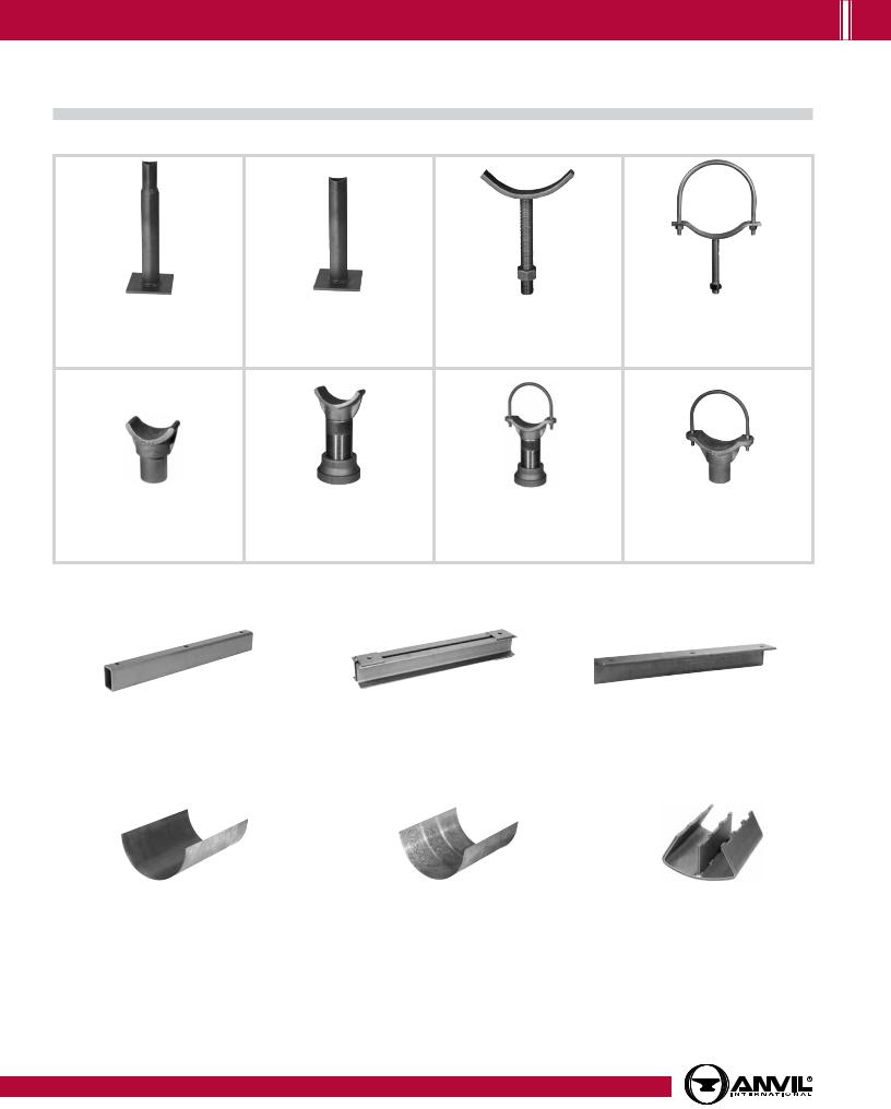
PIPE SUPPORTS
Fig. 62 |
Fig. 63 |
Fig. 192 |
Fig. 191 |
Type A, B, and C Pipe Stanchion |
Type A, B, and C Pipe Stanchion |
Adjustable Pipe Saddle |
Adjustable Pipe Saddle with U-Bolt |
Size Range: 2" thru 18" |
Size Range: 21/2" thru 42" |
Size Range: 2" thru 12" |
Size Range: 2" thru 12" |
Page 110 |
Page 111 |
Page 112 |
Page 112 |
Fig. 258 |
Fig. 264 |
Fig. 265 |
Fig. 259 |
Pipe Stanchion Saddle |
Adjustable Pipe Saddle Support |
Adjustable Pipe Saddle Support with U-Bolt |
Pipe Saddle Support with U-Bolt |
Size Range: 4" thru 36" |
Size Range: 21/2" thru 36" |
Size Range: 4" thru 36" |
Size Range: 4" thru 36" |
Page 113 |
Page 114 |
Page 115 |
Page 116 |
TRAPEZE
|
Fig. 45 |
Fig. 50 |
Universal Trapeze Assembly |
Channel Assembly |
Equal Leg Angle for Trapeze Assembly |
Page 117 |
Page 118 |
Page 119 |
|
|
|
PIPE SHIELDS & SADDLES
Fig. 167 |
Fig. 168 |
Fig. 160 to 166A |
Insulation Protection Shield |
Rib-Lok Shield |
Pipe Covering Protection Saddle |
Size Range: 1/2" thru 24" pipe with up to 2" thick insulation |
Size Range: 1/2" thru 8" pipe or copper tube with up to 2" thick insulation |
Size Range: 3/4" thru 36" |
Page 120 |
Page 121 |
Pages 122 - 125 |
|
|
|
12 |
www.anvilintl.com |
PH-3.16
PICTORIAL TABLE OF CONTENTS 


Pipe Rolls –– Pipe Guides & Slides
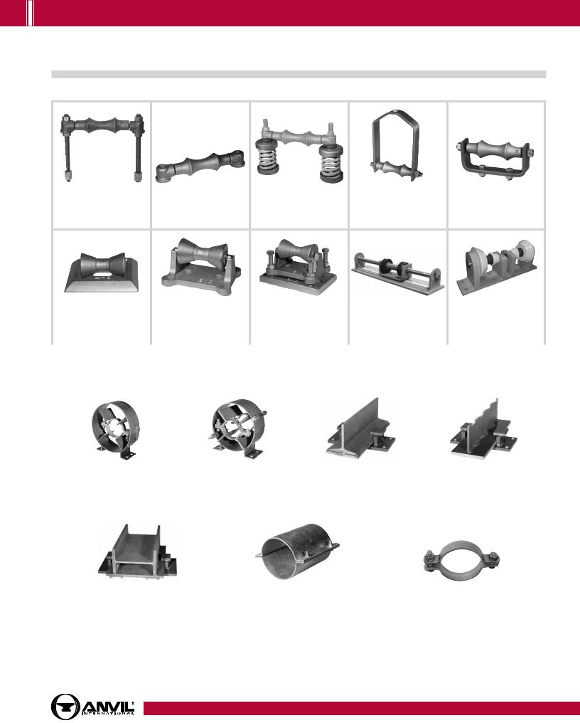
PIPE ROLLS
Fig. 177 |
Fig. 171 |
Fig. 178 |
Fig. 181 |
Fig. 175 |
Adjustable Pipe Roll Support |
Single Pipe Roll |
Spring Cushion Hanger |
Adjustable Steel Yoke Pipe Roll |
Roller Chair |
Size Range: 1" thru 30" |
Size Range: 1" thru 30" |
Page 128 |
Size Range: 21/2" thru 24" |
Size Range: 2" thru 30" pipe |
Page 126 |
Page 127 |
|
Page 129 |
Page 130 |
Fig. 277 |
|
Fig. 271 |
Fig. 274, 274P & 275 |
Fig. 75LL |
|
Fig. 76CP |
|||||
Pipe Roll and Base Plate |
|
Pipe Roll Stand |
Adjustable Pipe Roll Stand |
Longitudinal & Lateral Roller |
Non-Conductive Roller |
||||||
Size Range: 2" thru 24" |
Size Range: 2" thru 42" |
Size Range: 2" thru 42" |
Page 134 |
|
Page 134 |
||||||
Page 131 |
|
Page 132 |
|
Page 133 |
|
|
|
|
|
||
|
|
|
|
|
|
|
|
|
|||
|
|
|
|
PIPE GUIDES & SLIDES |
|
|
|||||
Fig. 255 |
|
|
Fig. 256 |
|
|
Fig. 257 & 257A |
|
Fig. 436 & 436A |
|||
Pipe Alignment Guide |
|
Pipe Alignment Guide |
|
|
Structural Tee Slide Assembly |
|
Fabricated Tee Slide Assembly |
||||
Size Range: 1" thru 24" pipe and insulation |
Size Range: 1" thru 24" pipe and insulation |
|
Size Range: |
|
Size Range: |
||||||
thickness of 1" thru 4" |
|
thickness of 1" thru 4" |
|
All sizes within maximum load rating |
All sizes within maximum load rating |
||||||
Pages 136 - 137 |
|
Pages 138 - 139 |
|
|
Pages 140 - 143 |
|
Pages 140 - 143 |
||||
|
|
|
|
|
|
|
|
|
|
|
|
Fig. 439 & 439A |
|
|
|
Fig. 432 |
|
|
|
|
Fig. 212 |
||
Structural "H" Slide Assembly, Complete |
|
|
Special Clamp |
|
|
|
Medium Pipe Clamp |
||||
Size Range: 6" thru 36" |
|
|
|
Size Range: 2" thru 24" |
|
|
Size Range: 2" thru 30" |
||||
Pages 144 - 145 |
|
|
|
|
Page 146 |
|
|
|
|
Page 147 |
|
|
|
|
|
|
|
|
|
|
|
|
|
Table of |
Contents |
|
|
General |
Notes |
|
|
Copper Tubing |
Hangers |
|
|
|
|
Stainless Steel |
Hangers |
|
|
CPVC |
Pipe Hangers |
|
|
|
|
Pipe |
Rings |
|
|
Clevis |
Hangers |
|
|
|
|
Steel Pipe |
Clamps |
|
|
|
|
Socket |
Clamps |
|
|
|
|
Beam |
Clamps |
|
|
|
|
Structural |
Attachments |
|
|
|
|
Brackets |
|
|
|
|
|
Ceiling Plates & Flanges |
|
|
|
|
|
Concrete Inserts |
& Attachments |
|
|
|
|
Hanger |
Rods |
|
|
|
|
Rod |
Attachments |
|
|
|
|
Bolts, Nuts, |
Pins & U-Bolts |
|
|
www.anvilintl.com |
13 |
PH-3.16


 PICTORIAL TABLE OF CONTENTS
Sway Brace - Seismic (Go to www.anvilintl.com/Product/SeismicSwayBracing.aspx for current Product Data Sheets)
PIPE BRACE CLAMPS
OPA-2804-10 |
OPA-2804-10 |
OPA-2804-10 |
|
|
|
|
|
|
Fig. 770 |
Fig. 776 |
Fig. 775 |
Q Brace Clamp |
Brace Clamp |
Lateral/Longitudinal Brace Clamp |
Size Range: 1" thru 6" Service Pipe |
Size Range: 21/2" thru 8" Service Pipe |
Size Range: 21/2" thru 8" Service Pipe |
Pages 148 - 149 |
Pages 150 - 151 |
Pages 152 - 153 |
|
STRUCTURAL ATTACHMENTS |
OPA-2804-10 |
OPA-2804-10 |
|
Fig. 778 |
|
Fig. 772 |
|
Fig. 779 |
|
Bar Joist and Beam Attachment (WF) |
|
Adjustable Steel Beam Attachment |
|
Multi-Connector Adapter |
|
Size Range: Flange Thickness 1/8" thru 3/4" |
|
Size Range: Flange Widths 4" thru 15" |
|
Size Range: 1" thru 8" Service Pipe |
|
Pages 154 - 155 |
|
Pages 156 - 158 |
|
Page 159 |
RESTRAINTS |
SWAY BRACE |
ATTACHMENT |
OPA-2804-10
|
Fig. 773 |
|
Fig. 777 |
|
Fig. 771 |
|
Surge Restrainer |
|
Swivel Joint Connector - Rod Tap |
|
Sway Brace Swivel Attachment |
|
Size Range: 3/4" thru 2" Swivel Ring Hanger |
|
Size Range: 3/8" Rod Diameter |
|
Size Range: 1" and 11/4" Brace Pipe |
|
Page 160 |
|
Page 161 |
|
Pages 162 -163 |
Go to www.anvilintl.com/OPA for State of California Office of Statewide Health Planning and Development (OSHPD) for design information relating to OSHPD projects.
Seis Brace® Seismic Fire Protection Design Tool may be accessed at www.seisbrace.com
Notes:
1.For fire protection installations - sway braces are intended to be installed in accordance with NFPA-13 and Anvil's installations instructions and local codes.
2.The required type, number and size of fasteners used for the structural attachment fitting shall be in accordance with NFPA-13.
3.To assure proper performance, installer is responsible for:
a.Structural integrity of attachment member to safely handle load requirements.
b.Securely tightening the component on the brace pipe.
4.Anvil International® brand bracing components are designed to be compatible ONLY with other Anvil International® brand bracing components, resulting in a Listed seismic bracing assembly.
5.Updated UL listing information may be viewed at www.ul.com and FM approvals may be viewed at www.fmgobal.com
Disclaimer: Anvil International (“Anvil”) does not provide any warranties and specifically disclaims any liability whatsoever with respect to Anvil bracing products and components that are used in combination with products, parts or systems not manufactured or sold by Anvil. In no event shall Anvil be liable for any incidental, direct, consequential, special or indirect damages or lost profits where non-Anvil bracing components have been, or are used.
14 |
www.anvilintl.com |
PH-3.16
PICTORIAL TABLE OF CONTENTS 


Spring Hangers –– Snubbers
SPRING HANGERS |
HORIZONTAL TRAVELER & SWAY BRACE |
Fig. 82 & C-82 |
Fig. B-268 & C-268 |
Fig. 98 & C-98 |
Short Spring |
Standard Spring |
Double Spring |
Pages 164 - 165, |
Pages 164 - 165, |
Pages 164 - 165, |
174 - 175 |
169 - 173 |
176 - 177 |
|
|
|
Triple Spring, Triple Spring-CR
Pages 164 - 165, 178 -179
Quadruple Spring, Quadruple Spring-CR
Pages 164 -165, 180 - 181
Fig. 170
Horizontal Traveler
Size Range: Available in four sizes to take loads to 20,700 (lbs.)
All sizes provide for 12" of horizontal travel.
Page 207
Fig. 296, 297, 298, 301, 302, 303
Sway Brace
Size Range: Preloads from 50 (lbs.) to 1,800 (lbs.) and maximum forces
from 200 (lbs.) to 7,200 (lbs.)
Pages 208 - 210
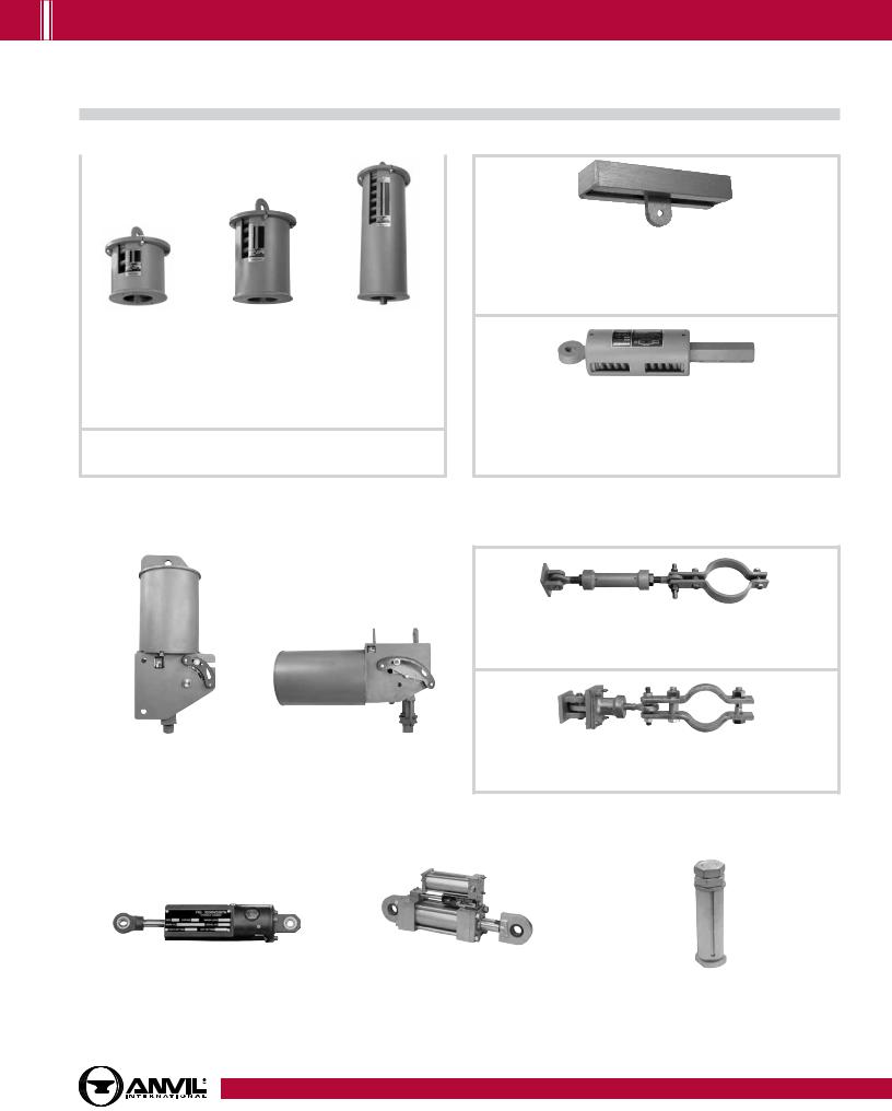
CONSTANT SUPPORTS
Model R Fig. 80-V |
Model R Fig. 81-H |
Vertical Constant Support |
Horizontal Constant Support |
Pages 182 - 197, 205 - 206 |
Pages 182 - 189, 198 - 206 |
|
|
SWAY STRUT ASSEMBLY
Fig. 211, C-211, 640, C-640
Sway Strut Assembly
Pages 211 - 212
Fig. 222 & C-222
Mini-Sway Strut Assembly
Pages 213 - 214
SNUBBERS
Fig. 3306 & 3307 |
Fig. 200, C-200, 201, C-201 |
|
|
Hydraulic Shock and Sway Suppressor (Snubber) |
Hydraulic Shock and Sway Suppressor (Snubber) |
Fig. 312 |
|
Size Range: Seven standard sizes with |
Size Range: Nine standard sizes with |
||
Tapered Pin |
|||
load ratings from 350 (lbs.) to 120,000 (lbs) |
load ratings from 3000 (lbs.) to 128,000 (lbs) |
||
Size Range: 3/8" thru 21/2" |
|||
Pages 216 - 219 |
Pages 220 - 223 |
||
Page 224 |
|||
|
|
Table of |
Contents |
|
|
General |
Notes |
|
|
Copper Tubing |
Hangers |
|
|
|
|
Stainless Steel |
Hangers |
|
|
CPVC |
Pipe Hangers |
|
|
|
|
Pipe |
Rings |
|
|
Clevis |
Hangers |
|
|
|
|
Steel Pipe |
Clamps |
|
|
|
|
Socket |
Clamps |
|
|
|
|
Beam |
Clamps |
|
|
|
|
Structural |
Attachments |
|
|
|
|
Brackets |
|
|
|
|
|
Ceiling Plates & Flanges |
|
|
|
|
|
Concrete Inserts |
& Attachments |
|
|
|
|
Hanger |
Rods |
|
|
|
|
Rod |
Attachments |
|
|
|
|
Bolts, Nuts, |
Pins & U-Bolts |
|
|
www.anvilintl.com |
15 |
PH-1.14


 GENERAL NOTES
Standard Materials
Anvil catalog items are made from the following materials.
Hanger Classification |
Material |
Material Specifications (ASTM) |
|
|
|
|
|
|
Malleable Iron |
A197 |
|
|
Ductile Iron |
A536-77 Grade 65-45-12 |
|
Beam Clamps |
Carbon Steel - Stamped |
A36 or A1011, CS, Type A, B, or C |
|
|
Carbon SteelFormed |
A575 Grade M1020 |
|
|
Forged Steel |
A668 or A1030 |
|
|
Carbon Steel - Rod |
A36 or AISI 1006-1015 |
|
Bolts, Nuts, Pins and U-Bolts |
Carbon Steel - Bolts |
A307 |
|
|
Carbon SteelNuts |
A563 |
|
|
Malleable Iron |
A197 |
|
Brackets |
Carbon Steel - Pre Galv. |
A653 |
|
|
Carbon Steel - Structural Shapes and Plate |
A36 |
|
|
Plastic |
N/A |
|
Ceiling Plates and Flanges |
Malleable Iron |
A197 |
|
|
Cast Iron |
A48 Grade 20 or A126 |
|
Clevis Hangers |
Carbon Steel - Stamped |
A1011, CS, Type A, B or C |
|
Clevis Hangers - Pipe or Conduit |
Carbon Steel |
A569 Grade 1008-1010 or A525 or A526 |
|
Clevis Hangers - Ductile Iron Pipe |
Carbon Steel |
A36, A569 |
|
|
Malleable Iron |
A197 |
|
Concrete Inserts and Attachments |
Carbon Steel - Stamped |
A1011 |
|
|
Carbon Steel - Formed and Fabricated |
A36 or A515 Grade 65-70 |
|
Copper Tubing Hangers |
Malleable Iron |
A197 |
|
Carbon Steel |
A1011, CS, Type A, B or C |
||
|
|||
Copper Tubing Hangers - Pipe Ring |
Carbon Steel |
A653 |
|
CPVC Hangers |
Carbon Steel |
A1011, CS, Type B |
|
Hanger Rods |
Carbon Steel |
A36 or A1006-1015 |
|
Pipe Alingment Guides |
Carbon Steel |
A36 or A1011, CS, Type A, B, or C |
|
Pipe Slides |
Carbon Steel - Structural Shapes or Plates |
A36 |
|
Pipe Rings |
Malleable Iron |
A197 |
|
Carbon Steel |
A653 |
||
|
|||
Pipe Roll - (2) Rod, Yoke & Chair |
Cast Iron |
A1010 or A1015 |
|
Pipe Roll - Stands |
Cast Iron |
A48 Gr 20 or A126 |
|
Pipe Protection Saddles |
Carbon Steel |
A36 or A1011, CS, Type A, B, or C |
|
Alloy Steel |
A387 Grade 22 Class 1 Annealed |
||
|
|||
Pipe Shields |
Carbon Steel |
A653 |
|
Pipe Supports - Stanchions |
Carbon Steel |
Tube: A513 Grade 1020 or 1026, Plate:A36 |
|
Pipe Supports - Saddles |
Carbon Steel |
A36 |
|
Cast Iron |
A48 Grade 20 or A126 |
||
|
|||
|
Malleable Iron |
A197 |
|
Rod Attachments |
Carbon Steel |
A36 |
|
|
Forged Steel |
A668 or A1030 |
|
Rod Attachments - Rod Couplings |
Carbon Steel |
A307 or A563 |
|
Socket Clamps |
Carbon Steel |
A36 |
|
Socket ClampsWashers |
Cast Iron |
A126 |
|
Carbon Steel |
A36 |
||
|
|||
Stainless Steel Hangers and Supports |
Refer to table note 1. |
|
|
Plate |
Stainless Steel |
A240 Type 304 |
|
Pipe |
Stainless Steel |
A312 Type 304 |
|
Rod and Pins |
Stainless Steel |
A276 Type 304 |
|
Bolts |
Stainless Steel |
18-8 Stainless |
|
Nuts |
Stainless Steel |
18-8 Stainless |
|
Steel Pipe ClampsOffset and Extended |
Carbon Steel |
A36 or A570 Grade C/D or AISI 1020 |
|
|
Carbon Steel - Stamped |
A36 or A1011, CS, Type A, B, or C |
|
Steel Pipe Clamps |
Carbon Steel - Formed |
A36 or A515 Grade 65-70 |
|
|
Chrome Molybdenum Steel |
A387 Grade 22 |
|
|
Malleable Iron |
A197 |
|
Straps |
Carbon Steel - Formed |
A36 |
|
|
Carbon Steel - Stamped |
A1011, CS, Type A, B, or C |
|
Structural Attachments - Washer Plates |
Carbon Steel |
A36 or AISI 1020 or A515 Grade 65-70 |
|
Structural Attachments |
Carbon Steel |
A36 or A515 Grade 65-70 |
|
Malleable / Ductile |
A197, A536-77 Grade 65-45-12 |
||
|
|||
Trapeze |
Carbon Steel - Structural Shapes |
A36 |
|
Carbon Steel - HSS |
A500 Grade B or C |
||
|
Notes: 1. Most Anvil hanger figure numbers are available in stainless steel on special order, primarily in type 304 and type 316. Items are limited.
2.Custom fabricated products can be furnished - to specifications provided by customer.
3.Standard material specifications are subject to change without notice.
16 |
www.anvilintl.com |
PH-11.11

GENERAL NOTES 


Standard Galvanizing Practice
Anvil offers 3 basic forms fo zinc coating on its hanger components
1)Electro-Plated Zinc (Electro-galvanized)
2)Pre-Galvanized Zinc
3)Hot Dipped Galvanized
Note: The corrosion resistance of zinc is based on its thickness, the environment and the coating process used.
Electro-Plated Zinc (ASTM B633)
This type of coating is recommended for use indoors in relatively dry areas. The steel is submersed in a bath of zinc salts, through the process of electrolysis, a coating of pure zinc adheres to the steel with a molecular bond. A maximum of .5 mills of zinc can be applied using this method. The threaded components and fasteners for Anvil hangers are furnished electroplated.
Pre-Galvanized Zinc (ASTM A653)
This type of coating is suitable for extended exposure in dry or mildly corrosive atmospheres, but not generally recommended for use outdoors in industrial environments. Also known as "mill galvanized" or "hot-dipped mill galvanized", pre-galvanized zinc coatings are produced by rolling the steel coils or sheets through molten zinc at the steel mill. The material is then cut or slit to size. Coating thickness is .90
ounces per square foot of steel surface. Zinc near the uncoated edges or weld areas becomes a sacrificial anode which protects the bare areas. Anvil uses this type of material on our Fig. 167 shields and Fig. 69 swivel ring hangers.
Hot-Dip Galvanized (ASTM 123 or ASTM 153)
Recommended for prolonged outdoor exposure and will usually protect steel in most atmospheric environments.
After fabrication, the part is immersed in a bath of molten zinc. A metallurgical bond is formed, resulting in a zinc coating that coats all surfaces including edges. Anvil's standard galvanizing practice for our Fig. 261 riser clamps and Fig. 212 medium pipe clamps is hot-dip galvanized.
Figure |
Description |
Standard |
|
Number |
Galvanize Finish |
||
|
|||
14 |
Adj. Side Beam Clamp |
EG |
|
40 |
Riser Clamp – Standard |
Hot Dip with EG Fasteners |
|
45 |
Channel Assembly |
Hot Dip |
|
46 |
Universal Trapeze Assembly |
Hot Dip |
|
47 |
Concrete Single Lug Plate |
Hot Dip |
|
49 |
Concrete Clevis Plate |
Hot Dip with EG Fasteners |
|
50 |
Equal Leg Angle for Trapeze Assembly |
Hot Dip |
|
52 |
Concrete Rod Attachment Plate |
Hot Dip |
|
54 |
Two Hole Welding Beam Lug |
Hot Dip |
|
55 |
Structural Welding Lug |
Hot Dip |
|
60 |
Steel Washer Plate |
Hot Dip |
|
62 |
Pipe Stanchion |
Hot Dip |
|
63 |
Pipe Stanchion |
Hot Dip |
|
65 |
Light Duty Adj. Clevis |
EG |
|
66 |
Welded Beam Attachment |
Hot Dip |
|
66 with BN |
Welded Beam Attachment |
Hot Dip with EG Fasteners |
|
67 |
Pipe or Conduit Hanger |
EG |
|
69 |
Adj. Swivel Ring, Tapped per NFPA |
Strap is Pre-Galv. Material, |
|
Standards |
Nut is EG (See Note 1) |
||
|
|||
76 |
Fabricated Roller for Large Dia. Pipe |
Galvanizing not possible, |
|
|
|
Paint Only |
Figure |
Description |
Standard |
|
Number |
Galvanize Finish |
||
|
|||
86 |
C-Clamp with Set Screw & Lock Nut |
EG |
|
88 |
C-Clamp with Set Screw |
EG |
|
89, 89X |
Retaining Clip |
EG |
|
92 |
Universal C-Type Clamp (Std. Throat) |
EG |
|
93 |
Universal C-Type Clamp (Wide Throat) |
EG |
|
94 |
Wide Throat Beam C-Clamp |
EG |
|
95 |
C-Clamp with Lock Nut |
EG |
|
100 |
Extended Pipe Clamp |
Hot Dip with EG Fasteners |
|
103 |
Offset Pipe Clamp |
Hot Dip with EG Fasteners |
|
104 |
Adj. Swivel Ring, Split Ring Type |
EG |
|
120 |
Light Weight U-Bolt |
EG |
|
126 |
One-Hole Clamp |
EG |
|
128R |
Rod Threaded Ceiling Flange |
EG |
|
133 |
Standard Duty Beam Clamp |
Hot Dip with EG Fasteners |
|
134 |
Heavy Duty Beam Clamp |
Hot Dip with EG Fasteners |
|
135E |
Rod Coupling Straight less Sight Hole |
EG |
|
135R |
Rod Coupling Reducing |
EG |
|
136 |
Rod Coupling Straight |
EG |
|
136R |
Rod Coupling Reducing |
EG |
|
137 |
Standard U-Bolt |
EG |
|
137S |
Special U-Bolt (non-standard) |
Hot Dip |
EG = Zinc Electro Plate ASTM B633 Hot Dip = ASTM A123 or A153 Pre-Galv. = ASTM A653
Most EG items and fasteners can be hot dip galvanized except as indicated. Hot Dipped galvanized all thread rod is available. Note 1 indicates that hot dip fasteners are not available.
Table of |
Contents |
|
|
|
|
General |
Notes |
|
|
Copper Tubing |
Hangers |
|
|
|
|
Stainless Steel |
Hangers |
|
|
CPVC |
Pipe Hangers |
|
|
|
|
Pipe |
Rings |
|
|
Clevis |
Hangers |
|
|
|
|
Steel Pipe |
Clamps |
|
|
|
|
Socket |
Clamps |
|
|
|
|
Beam |
Clamps |
|
|
|
|
Structural |
Attachments |
|
|
|
|
Brackets |
|
|
|
|
|
Ceiling Plates & Flanges |
|
|
|
|
|
Concrete Inserts |
& Attachments |
|
|
|
|
Hanger |
Rods |
|
|
|
|
Rod |
Attachments |
|
|
|
|
Bolts, Nuts, |
Pins & U-Bolts |
|
|
www.anvilintl.com |
17 |
PH-1.15


 GENERAL NOTES
Standard Galvanizing Practice (cont.)
Figure |
Description |
Standard |
|
Number |
Galvanize Finish |
||
|
|||
138R |
Ext. Split Pipe Clamp (Rod Threaded) |
EG |
|
140 |
Machine Threaded Rod (RH Threads) |
EG |
|
142 |
Coach Screw Rod |
EG |
|
146 |
Continuous Threaded Rod |
EG |
|
148 |
Rod with Eye End |
EG |
|
157 |
Extension Piece |
EG |
|
167 |
Insulated Protection Shield |
Pre-Galv. Material |
|
168 |
Rib-Lok Shield |
Pre-Galv. Material |
|
171 |
Single Pipe Roll |
EG |
|
175 |
Roller Chair |
Chair-Hot Dip, All Other EG |
|
177 |
Adj. Pipe Roll Support |
EG |
|
178 |
Spring Cushion Hanger |
Can Galv. Retainer, Springs |
|
Paint Only |
|||
|
|
||
181 |
Adj. Steel Yoke Pipe Roll |
Hot Dip Yoke, All Other EG |
|
185 |
One Hole Pipe Strap |
EG |
|
186 |
Two Hole Pipe Strap |
EG |
|
187 |
Two Hole 90˚ Side Mount Strap |
EG |
|
188 |
Two Hole Stand Off Strap |
EG |
|
189 |
Straight Eye Socket |
Pre-Galv. |
|
190 |
Off-Set Eye Socket |
Pre-Galv. |
|
191 |
Adj. Pipe Saddle with U-Bolt |
EG |
|
192 |
Adj. Pipe Saddle |
EG |
|
194 |
Light Welded Steel Bracket |
Hot Dip |
|
195 |
Medium Welded Steel Bracket |
Hot Dip |
|
199 |
Heavy Welded Steel Bracket |
Hot Dip |
|
206 |
Steel Side Beam Bracket |
EG |
|
207 |
Threaded Steel Side Beam Bracket |
EG |
|
212 |
Medium Pipe Clamp |
Hot Dip with EG Bolts & Nuts |
|
212FP |
Earthquake Bracing Clamp |
Hot Dip with EG Bolts & Nuts |
|
216 |
Heavy Pipe Clamp |
Hot Dip with EG Bolts & Nuts |
|
218 |
Malleable Beam Clamp without Ext. |
EG |
|
Piece |
|||
|
|
||
228 |
Universal Forged Steel Beam Clamp |
EG |
|
230 |
Turnbuckle |
EG |
|
233 |
Turnbuckle |
EG |
|
248, 248L, |
Eye Rod Not Welded |
EG |
|
248X |
|
|
|
253 |
Machine Threaded Rod (Threaded Both |
EG |
|
Ends) |
|||
|
|
||
255 |
Pipe Alignment Guide |
Hot Dip with EG Bolts & Nuts |
|
|
|
Housing: Hot Dip with EG |
|
CT-255 |
Copper Tubing Alignment Guide |
Bolts & Nuts |
|
|
|
Spider Clamp: Copper Plated |
|
|
|
|
|
256 |
Pipe Alignment Guide |
Hot Dip with EG Bolts & Nuts |
|
257 |
Structural Tee Slide |
Hot Dip, Weld after Galv. & |
|
Cold Spray Touch-up |
|||
|
|
||
258 |
Pipe Saddle Support |
EG |
|
259 |
Pipe Saddle Support with U-Bolt |
EG |
|
|
|
8" & Smaller: EG |
|
260 |
Adj. Clevis Hanger |
10" & Larger: Hot Dip with |
|
|
|
EG Bolts & Nuts |
|
|
|
|
|
260 ISS |
Clevis Hanger with Insulation Saddle |
Reference Fig. 260 |
|
|
System |
|
Figure |
Description |
Standard |
|
Number |
Galvanize Finish |
||
|
|||
261 |
Ext. Pipe or Riser Clamp |
Hot Dip with EG Bolts & Nuts |
|
262 |
Strap Short |
EG |
|
|
|
EG (See Note 1) |
|
264 |
Adj. Pipe Saddle Support |
Nippl red. assembly cannot |
|
|
|
be hot dipped. |
|
|
|
|
|
|
|
EG (See Note 1) |
|
265 |
Adj. Pipe Saddle Support with U-Bolt |
Nippl red. assembly cannot |
|
|
|
be hot dipped. |
|
|
|
|
|
271 |
Pipe Roll Stand |
EG |
|
274 |
Adj. Pipe Roll Stand with Base Plate |
EG |
|
274P |
Pipe Roll Stand - Base Plate Only |
EG |
|
275 |
Adj. Pipe Roll Stand without Base Plate |
EG |
|
277 |
Pipe Roll and Base Plate |
EG |
|
278, 278L, |
Eye Rod Welded |
EG |
|
278X |
|
|
|
281 |
Wedge Type Concrete Insert |
EG (See Note 1) |
|
282 |
Universal Concrete Insert |
EG (See Note 1) |
|
285 |
Light Weight Concrete Insert |
EG (See Note 1) |
|
290, 290L |
Weldless Eye Nut |
EG |
|
291 |
Clevis Pin with Cotters |
EG |
|
292, 292L |
Universal Forged Steel Beam Clamp |
EG |
|
295 |
Double Bolt Pipe Clamp |
Hot Dip with EG Bolts & Nuts |
|
295A |
Alloy Double Bolt Pipe Clamp |
Alloy Material, Galv. is not |
|
Recommended |
|||
|
|
||
295H |
Heavy Duty Double Bolt Pipe Clamp |
Hot Dip with EG Bolts & Nuts |
|
299 |
Forged Steel Clevis |
EG |
|
|
|
8" & Smaller: EG |
|
300 |
Adj. Clevis for Insulated Lines |
10" & Larger: Hot Dip with |
|
|
|
EG Bolts & Nuts |
|
|
|
|
|
395 |
Cast Iron Ceiling Plate |
EG |
|
432 |
Special Clamp |
Hot Dip with EG Bolts & Nuts |
|
436 |
Fabricated Tee Slide Assembly |
Hot Dip, Weld after Galv. & |
|
Cold Spray Touch-up |
|||
|
|
||
439 |
Structural "H" Slide Assembly |
Hot Dip, Weld after Galv. & |
|
Cold Spray Touch-up |
|||
|
|
||
590 |
Adj. Clevis for Ductile or Cast Iron |
Hot Dip with EG Bolts & Nuts |
|
Pipe |
|||
|
|
||
594 |
Socket Clamp Washer |
EG |
|
595 |
Socket Clamp for Ductile Iron or Cast |
Hot Dip with EG Bolts & Nuts |
|
|
Iron Pipe |
|
|
599 |
Socket Clamp Washer |
EG |
|
600 |
Socket Clamp for Ductile Iron or Cast |
Hot Dip with EG Bolts & Nuts |
|
|
Iron Pipe |
|
|
770 |
Q-Brace Clamp |
EG (See Note 2) |
|
771 |
Sway Brace Swivel Attachment |
EG |
|
772 |
Adj. Steel Beam Attachment |
EG |
|
773 |
Surge Restrainer |
EG |
|
775 |
Lateral/Longitudinal Brace Clamp |
EG |
|
776 |
Brace Clamp |
EG |
|
777 |
Swivel Joint Connector |
EG |
|
778 |
Bar Joist and Beam Attachment |
EG |
|
779 |
Multi-Connector Adapter |
EG |
EG = Zinc Electro Plate ASTM B633 Hot Dip = ASTM A123 or A153 Pre-Galv. = ASTM A653
Most EG items and fasteners can be hot dip galvanized except as indicated. Hot Dipped galvanized all thread rod is available.
Note 1 indicates that hot dip fasteners are not available.
18 |
www.anvilintl.com |
PH-3.16

com.anvilintl.www
19
NOTES GENERAL
Bolts, Nuts, |
|
Rod |
|
Hanger |
|
Concrete Inserts |
|
Ceiling Plates |
|
Brackets |
|
Structural |
|
Beam |
|
Socket |
|
Steel Pipe |
|
Clevis |
|
Pipe |
|
CPVC |
|
Stainless Steel |
|
Copper Tubing |
|
General |
|
Table of |
Pins & U-Bolts |
|
Attachments |
|
Rods |
|
& Attachments |
|
& Flanges |
|
|
|
Attachments |
|
Clamps |
|
Clamps |
|
Clamps |
|
Hangers |
|
Rings |
|
Pipe Hangers |
|
Hangers |
|
Hangers |
|
Notes |
|
Contents |
|
|
|
|
|
|
|
|
|
|
|
|
|
|
|
|
|
|
|
|
|
|
|
|
|
|
|
|
|
|
|
|
|
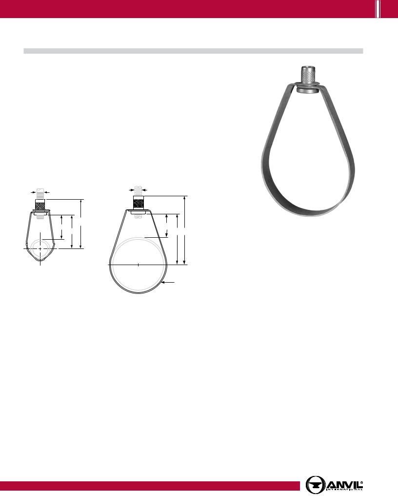


 COPPER TUBING HANGERS
Fig. CT-69
Adjustable Swivel Ring
Size Range: 1⁄2" through 4"
Material: Carbon steel
Finish: Copper plated
Service: Recommended for suspension of non-insulated stationary copper tube.
Approvals: Complies with Federal Specification A-A-1192A (Type 10)
WW-H-171-E (Type 10), ANSI/MSS SP-69 and MSS SP-58 (Type 10).
Features:
•Threads are countersunk so that they cannot become burred or damaged.
•Knurled swivel nut provides vertical adjustment after piping is in place.
•Captured swivel nut will not fall off.
Ordering: Specify nominal tube size, figure number, name and finish.
Note: Metric nut available upon request.
3 |
⁄8" |
3⁄8" |
|
|
|
|
|
B |
|
F |
F |
|
C |
C B |
C
L
 G C L
G C L
1/2" through 11/4" pipe
G
11/2" through 4" pipe
|
|
FIG. CT-69: LOADS (LBS) • WEIGHT (LBS) • DIMENSIONS (IN) |
|
||||
|
|
|
|
|
|
|
|
|
Tube Size |
Max Load |
Weight |
B |
C |
F |
G |
|
Width |
||||||
|
|
|
|
|
|
|
|
|
|
|
|
|
|
|
|
|
1⁄2 |
|
0.10 |
3 |
23⁄16 |
17⁄8 |
|
|
3⁄4 |
|
0.10 |
213⁄16 |
2 |
19⁄16 |
|
|
1 |
300 |
0.10 |
211⁄16 |
113⁄16 |
11⁄4 |
5/8 |
|
11⁄4 |
0.10 |
21⁄2 |
15⁄8 |
15⁄16 |
||
|
|
|
|||||
|
11⁄2 |
|
0.10 |
211⁄16 |
113⁄16 |
1 |
|
|
2 |
|
0.11 |
37⁄16 |
21⁄2 |
11⁄2 |
|
|
21⁄2 |
525 |
0.25 |
313⁄16 |
215⁄16 |
111⁄16 |
|
|
3 |
0.27 |
41⁄4 |
33⁄8 |
17⁄8 |
3/4 |
|
|
|
||||||
|
4 |
650 |
0.48 |
43⁄8 |
31⁄2 |
11/2 |
|
|
Note: Reflects changes in rod diameter from previously published data per recent revisions in MSS-SP-58 & 69 |
|
|
||||
20 |
|
|
|
|
www.anvilintl.com |
|
|
PH-11.11
COPPER TUBING HANGERS 


Fig. CT-65 |
Light Duty Adjustable Clevis |
|
|
|
|
Size Range: 1⁄2" through 4"
Material: Carbon steel
Finish: Copper plated
Service: Recommended for suspension of non-insulated, stationary copper tube.
Approvals: Complies with Federal Specification WW-H-171-E (Type 12).
Installation:
(1)Adjustment may be made either before or after tubing is in place without temporary support of pipe.
(2)Hanger rod and nuts may be locked into position after adjustment by use of the upper nut.
Features: Provides for adjustment up to 1 7⁄8".
Ordering: Specify nominal tube size, figure number, name and finish
A 
F
B
E
C
C
L
G
FIG. CT-65: LOADS (LBS) • WEIGHT (LBS) • DIMENSIONS (IN)
Tube |
Max Load |
Weight |
Rod Size |
B |
C |
D |
Rod Take |
Adjustment |
G Width |
|
Size |
A |
Out - E |
F |
Lower |
||||||
|
|
|
|
|
||||||
|
|
|
|
|
|
|
|
|
|
|
1⁄2 |
150 |
0.09 |
|
11⁄2 |
127⁄32 |
17⁄16 |
11⁄16 |
5⁄16 |
5/8 |
|
3⁄4 |
0.10 |
|
111⁄16 |
23⁄32 |
19⁄16 |
11⁄4 |
7⁄16 |
|
||
|
|
|
||||||||
1 |
|
0.17 |
|
17⁄8 |
213⁄32 |
15⁄8 |
17⁄16 |
1⁄2 |
|
|
11⁄4 |
250 |
0.18 |
|
25⁄32 |
213⁄16 |
13⁄4 |
111⁄16 |
5⁄8 |
|
|
11⁄2 |
0.21 |
3⁄8 |
217⁄32 |
33⁄8 |
115⁄16 |
21⁄16 |
13⁄16 |
3/4 |
||
|
||||||||||
2 |
|
0.26 |
|
311⁄32 |
417⁄32 |
25⁄16 |
27⁄8 |
13⁄16 |
||
|
|
|
||||||||
21⁄2 |
350 |
0.48 |
|
327⁄32 |
59⁄32 |
23⁄4 |
31⁄4 |
15⁄16 |
|
|
3 |
0.55 |
|
415⁄32 |
67⁄32 |
3 |
37⁄8 |
15⁄8 |
|
||
|
|
|
||||||||
4 |
400 |
0.60 |
|
431⁄32 |
631⁄32 |
31⁄4 |
43⁄8 |
17⁄8 |
|
Note: 1) Reflects changes in rod diameter from previously published data per recent revisions in MSS-SP-58 & 69. 2) 31/2" tube size alternate - 31/2" Fig. 65 galvanized.
Table of |
Contents |
|
|
|
|
General |
Notes |
|
|
Copper Tubing |
Hangers |
|
|
Stainless Steel |
Hangers |
|
|
CPVC |
Pipe Hangers |
|
|
|
|
Pipe |
Rings |
|
|
Clevis |
Hangers |
|
|
|
|
Steel Pipe |
Clamps |
|
|
|
|
Socket |
Clamps |
|
|
|
|
Beam |
Clamps |
|
|
|
|
Structural |
Attachments |
|
|
|
|
Brackets |
|
|
|
|
|
Ceiling Plates & Flanges |
|
|
|
|
|
Concrete Inserts |
& Attachments |
|
|
|
|
Hanger |
Rods |
|
|
|
|
Rod |
Attachments |
|
|
|
|
Bolts, Nuts, |
Pins & U-Bolts |
|
|
www.anvilintl.com |
21 |
PH-11.11


 COPPER TUBING HANGERS
Fig. CT-128R
Rod Threaded Ceiling Flange
Size Range: 3⁄8" and 1⁄2"
Material: Malleable iron
Finish: Copper plated
Service: Recommended for attachment to wood beams or ceiling.
Ordering: Specify rod size, figure number, name.
|
3⁄16" |
|
|
|
|
|
21⁄4" |
|
|
|
|
|
|
|
|
1⁄2" |
|
|
|
|
A |
|
|
|
|
|
|
|
|
|
FIG. CT-128R: |
|
|
|
35⁄16" |
|
LOADS (LBS) • WEIGHT (LBS) • DIMENSIONS (IN) |
||||
|
|
Rod Size |
Max Load |
Weight |
Screws |
|
|
|
A |
Quantity |
Size No. |
||
|
13⁄8" |
|
|
|||
|
3⁄8 |
|
|
|
|
|
|
|
180 |
0.16 |
2 |
12 |
|
|
|
1⁄2 |
||||
|
|
|
|
|
|
|
Fig. CT-138R
Extension Split Tubing Clamp (Rod Threaded)
Size Range: 1⁄2" through 2"
Material: Malleable iron
Finish: Copper plated
Service: Recommended for suspension of non-insulated stationary copper tube.
Approvals: Complies with Federal Specification A-A-1192A (Type 12)
WW-H-171-E (Type 25), ANSI/MSS SP-69 and MSS SP-58 (Type 12).
Installation:
•Permanent installation of clamp may be made before the tubing is placed in position.
•Final installation is attained by swinging the lower portion of the hinged clamp up under the tubing and inserting a single screw securely.
Features:
•Hinged design provides for economical installation.
•Designed to provide a tight fit on copper tubing. Ordering: Specify nominal tube size, figure number, name.
|
|
3⁄8" |
|
|
|
|
|
|
|
|
|
|
|
|
|
FIG. CT-138R: |
|
|
|
|
|
|
LOADS (LBS) • WEIGHT (LBS) • DIMENSIONS (IN) |
||||||
|
|
B |
Tube Size Max Load Weight |
A |
B |
||||
|
L |
|
|||||||
|
|
|
⁄2 |
|
0.10 |
2 |
|
⁄4 |
|
|
C |
|
1 |
|
|
|
|
3 |
|
|
|
|
3⁄4 |
|
0.12 |
21⁄4 |
7⁄8 |
||
|
|
|
1 |
180 |
0.14 |
21⁄2 |
1 |
||
|
|
|
11⁄4 |
0.18 |
27⁄8 |
11⁄8 |
|||
|
|
|
|
||||||
3⁄4" Thickness |
|
|
11⁄2 |
|
0.22 |
31⁄4 |
11⁄4 |
||
All Sizes |
A |
|
2 |
|
0.36 |
4 |
19⁄16 |
||
22 |
|
|
|
|
www.anvilintl.com |
|
|
|
|
PH-1.14

COPPER TUBING HANGERS 


Fig. 69F |
Adjustable Swivel Ring, Felt Lined |
|
|
|
|
Size Range: 1⁄2" through 6" copper tube
Material: Carbon steel and felt with adhesive backing
Finish: Strap is Pre-Galvanized Material. Nut is Zinc Plated.
Service: Recommended for suspension of non-insulated stationary copper tubing.
Maximum Temperature: 120° F
Approvals: Complies with Federal Specification A-A-1192A (Type 10)
WW-H-171-E (Type 10), ANSI/MSS SP-69 and MSS SP-58 (Type 10).
Features:
•The layer of felt separates the copper tubing from the steel ring for electrolytic resistance and also minimizes noise and vibration.
•Threads are countersunk so they cannot become burred or damaged.
•Knurled swivel nut provides vertical adjustment after tubing is in place.
•The captured nut is permanent in the bottom portion of band, allowing the hanger to be opened during installation if desired, but not allowing the nut to fall out.
Ordering: Specify felt ring size, figure number and name.
 A
A
|
|
|
FELT LINED RING: |
|
A |
|
|
IPS SIZING • DIMENSIONS (IN) |
|
F |
|
|
|
|
|
B |
Pipe Size |
Felted Ring Size |
|
|
|
1⁄2 |
1⁄2 - 1 |
|
|
C |
|
||
|
B |
|
3⁄4 |
11⁄4 |
F |
|
1 |
11⁄4 |
|
C |
C |
|
11⁄4 |
2 |
|
L |
|
11⁄2 |
2 |
C |
|
|
||
|
|
2 |
1 |
|
L |
|
|
2 ⁄2 |
|
G |
G |
|
21⁄2 |
3 |
|
|
3 |
4 |
|
|
|
|
||
1/2" & 3/4" tube |
1" through 6" tube |
|
4 |
5 |
1/2" through 1" Felted Ring |
11/4" through 6" Felted Ring |
|
5 |
6 |
Table of |
Contents |
|
|
|
|
General |
Notes |
|
|
Copper Tubing |
Hangers |
|
|
Stainless Steel |
Hangers |
|
|
CPVC |
Pipe Hangers |
|
|
|
|
Pipe |
Rings |
|
|
Clevis |
Hangers |
|
|
|
|
Steel Pipe |
Clamps |
|
|
|
|
Socket |
Clamps |
|
|
|
|
Beam |
Clamps |
|
|
|
|
Structural |
Attachments |
|
|
|
|
Brackets |
|
|
|
|
|
Ceiling Plates & Flanges |
|
|
|
FIG. 69F: LOADS (LBS) • WEIGHT (LBS) • DIMENSIONS (IN)
Tube Size |
Felted |
Max Load |
Rod Size A |
B |
C |
F |
G |
Weight |
|
Ring Size |
Width |
||||||||
|
|
|
|
|
|
|
|||
|
|
|
|
|
|
|
|
|
|
1⁄2 |
1⁄2 - 1 |
|
|
23⁄4 |
17⁄8 |
13⁄8 |
|
0.10 |
|
3⁄4 |
|
|
25⁄8 |
111⁄16 |
11⁄8 |
|
0.10 |
||
|
|
|
|
||||||
1 |
11⁄4 |
300 |
|
27⁄16 |
19⁄16 |
113⁄16 |
5/8 |
0.10 |
|
11⁄4 |
|
21⁄2 |
15⁄8 |
13⁄16 |
0.10 |
||||
|
|
|
|
||||||
11⁄2 |
11⁄2 |
|
3⁄8 |
25⁄8 |
13⁄4 |
3⁄4 |
|
0.10 |
|
2 |
2 |
|
|
31⁄8 |
21⁄4 |
1 |
|
0.10 |
|
21⁄2 |
21⁄2 |
525 |
|
37⁄8 |
25⁄8 |
113⁄16 |
|
0.20 |
|
3 |
3 |
|
33⁄4 |
27⁄8 |
|
0.20 |
|||
|
|
|
|
||||||
4 |
4 |
650 |
|
45⁄8 |
33⁄4 |
19⁄16 |
3/4 |
0.30 |
|
5 |
5 |
1,000 |
1⁄2 |
51⁄4 |
45⁄16 |
15⁄8 |
|
0.54 |
|
6 |
6 |
611⁄16 |
59⁄16 |
23⁄8 |
|
0.65 |
|||
|
|
|
Concrete Inserts |
& Attachments |
|
|
|
|
Hanger |
Rods |
|
|
|
|
Rod |
Attachments |
|
|
|
|
Bolts, Nuts, |
Pins & U-Bolts |
|
|
www.anvilintl.com |
23 |
PH-1.15
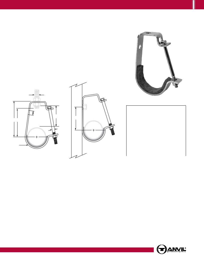


 COPPER TUBING HANGERS
Fig. 67F |
Copper Tube Felt Lined Hanger |
|
|
|
|
Size Range: 1⁄2" through 6" copper tube
Material: Carbon steel and felt with adhesive backing Finish: Zinc Plated (Hot-Dip Galvanized optional)
Service: Can be suspended by hanger rod or attached to wall. “T” slot in hanger permits side bolt to be installed after installation and setting of pipe.
Maximum Temperature: 120˚F
Approvals: Complies with Federal Specification A-A-1192A (Type 5), ANSI/MSS SP-69 and MSS SP-58 (Type 5).
Features: The layer of felt separates the copper tubing from the steel strap for electrolytic resistance and also minimizes noise and vibration.
Components: Strap and bolt with nut – assembled. Ordering: Specify felt hanger size, figure number and name.
A
E |
|
|
D |
F |
|
B G |
||
|
||
C |
C |
|
L |
||
C |
|
|
L |
|
|
H |
Alternate Installation |
|
|
Bolt/Screw to Vertical Support |
FELT LINED HANGER:
IPS SIZING • DIMENSIONS (IN)
Pipe Size |
Felted Hanger Size |
|
|
3⁄4 |
11⁄4 |
1 |
11⁄2 |
11⁄4 |
2 |
11⁄2 |
2 |
2 |
21⁄2 |
21⁄2 |
3 |
3 |
4 |
4 |
5 |
5 |
6 |
|
|
|
FIG. 67F: LOADS (LBS) • WEIGHT (LBS) • DIMENSIONS (IN) |
|
|
|||||||
|
|
|
|
|
|
|
|
|
|
|
|
|
|
Tube |
Felt |
Load |
Rod Size |
B |
C |
D |
E |
F |
G |
H |
Weight |
|
Size |
Hanger Size |
Rating |
A |
Width |
|||||||
|
|
|
|
|
|
|
|
|||||
|
|
|
|
|
|
|
|
|
|
|
|
|
|
1⁄2 |
3⁄4 |
|
|
21⁄2 |
|
15⁄8 |
|
15⁄16 |
13⁄4 |
|
0.22 |
|
3⁄4 |
1 |
|
|
211⁄16 |
|
111⁄16 |
|
11⁄2 |
115⁄16 |
|
0.25 |
|
1 |
11⁄4 |
400 |
3⁄8 |
213⁄16 |
1⁄4 |
113⁄16 |
7⁄16 |
15⁄8 |
21⁄8 |
1 |
0.27 |
|
11⁄4 |
11⁄4 |
31⁄8 |
17⁄8 |
2 |
29⁄16 |
0.27 |
|||||
|
|
|
|
|
|
|||||||
|
11⁄2 |
11⁄2 |
|
|
37⁄16 |
|
21⁄16 |
|
25⁄16 |
23⁄4 |
|
0.29 |
|
2 |
2 |
|
|
39⁄16 |
|
2 |
|
27⁄16 |
215⁄16 |
|
0.31 |
|
21⁄2 |
21⁄2 |
500 |
1⁄2 |
45⁄16 |
|
25⁄16 |
|
31⁄16 |
31⁄2 |
|
0.71 |
|
3 |
3 |
43⁄4 |
|
21⁄2 |
|
31⁄2 |
41⁄16 |
|
0.78 |
||
|
|
|
|
|
|
|||||||
|
4 |
4 |
550 |
5⁄8 |
61⁄16 |
3⁄8 |
31⁄8 |
9⁄16 |
45⁄8 |
53⁄16 |
11/4 |
1.39 |
|
5 |
5 |
611⁄16 |
|
33⁄16 |
|
51⁄8 |
513⁄16 |
|
1.66 |
||
|
|
|
|
|
|
|||||||
|
6 |
6 |
600 |
3⁄4 |
73⁄4 |
|
39⁄16 |
|
515⁄16 |
63⁄4 |
|
2.26 |
24 |
|
|
|
|
|
|
|
www.anvilintl.com |
|
|
||
PH-1.15
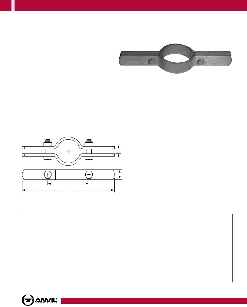
COPPER TUBING HANGERS 


Fig. CT-121 |
Copper Tubing Riser Clamp |
|
|
|
|
Size Range: 1⁄2" through 4" Material: Carbon steel Finish: Copper plated
Service: Recommended for support and steadying of copper tube risers, either insulated or non-insulated. This product is not intended for use with hanger rods. Approvals: Complies with Federal Specification A-A-1192A (Type 8), WW-H-171-E (Type 8), ANSI/MSS SP-69 and MSS SP-58 (Type 8).
Service: For support and steadying of copper tubing risers. Installation: Clamp is fitted and bolted preferably below a coupling or fitting on the tubing. Do not over tighten bolts.
Features: Rounded ears provide greater safety for personnel. Ordering: Specify tube size, figure number, and name.
C
C
L
G
B
L
FIG. CT-121: LOADS (LBS) • WEIGHT (LBS) • DIMENSIONS (IN) • TORQUE (FT-LBS)
Tube Size |
Max Load |
Weight |
L |
G |
Bolt Size |
Torque Values |
|
Width |
|||||||
|
|
|
|
|
|
||
|
|
|
|
|
|
|
|
1⁄2 |
75 |
0.52 |
61⁄2 |
1 |
5⁄16 |
11 |
|
3⁄4 |
0.56 |
7 |
|||||
|
|
|
|
||||
1 |
120 |
0.94 |
93⁄8 |
|
|
|
|
11⁄4 |
|
0.98 |
95⁄8 |
|
|
|
|
11⁄2 |
150 |
1.50 |
10 |
|
|
|
|
2 |
|
1.50 |
103⁄8 |
11⁄4 |
3⁄8 |
21 |
|
21⁄2 |
|
1.70 |
1113⁄16 |
|
|
|
|
3 |
300 |
1.80 |
111⁄2 |
|
|
|
|
31⁄2 |
1.90 |
12 |
|
|
|
||
|
|
|
|
||||
4 |
|
2.60 |
13 |
1 |
1⁄2 |
46 |
Note: Minimum loads per MSS SP only applicable to 11/4" and up.
Table of |
Contents |
|
|
|
|
General |
Notes |
|
|
Copper Tubing |
Hangers |
|
|
Stainless Steel |
Hangers |
|
|
CPVC |
Pipe Hangers |
|
|
|
|
Pipe |
Rings |
|
|
Clevis |
Hangers |
|
|
|
|
Steel Pipe |
Clamps |
|
|
|
|
Socket |
Clamps |
|
|
|
|
Beam |
Clamps |
|
|
|
|
Structural |
Attachments |
|
|
|
|
Brackets |
|
|
|
|
|
Ceiling Plates & Flanges |
|
|
|
|
|
Concrete Inserts |
& Attachments |
|
|
|
|
Hanger |
Rods |
|
|
|
|
Rod |
Attachments |
|
|
|
|
Bolts, Nuts, |
Pins & U-Bolts |
|
|
www.anvilintl.com |
25 |
PH-3.16


 COPPER TUBING HANGERS
Fig. CT-255
Copper Tubing Alignment Guide
Size Range: 1" through 4" Material: Carbon steel
Finish: Plain or Hot-Dip Galvanized Housing with Zinc Plated Bolts and Nuts. (Hot-Dip Galvanized optional) Copper Plated Finish on Spider Clamp. Service: For maintaining alignment of tubing through its axial expansion and contraction cycles. Normally, two or more pipe alignment
guides are used on a single tubing run to avoid a pivoting effect within the tubing system. Consult the Expansion Joint Manufacturers
Association or the Copper Tube Manufacturers for additional guidelines of spacing requirements of intermediate guides. Supports are usually required between intermediate guides to comply with standard support practices.
Maximum Temperature: 400° F
Installation:
(1)Attach outer housing to structure by bolting or welding.
(2)Remove upper section of housing to open position.
(3)Attach spider clamp to tube and completely insulate.
(4)Set tube and spider clamp into outer housing.
(5)Replace upper section of housing to closed position and secure. Note: Spider attachments to tube must be properly located during installation to insure that a minimum of one-half the spider width remains
within the length of the outer housing for all conditions of operation. If larger travels are required, special guides can be furnished to special order.
How to size: Size by nominal tube size and insulation thickness in accordance with the selection table.
Ordering: Specify size number, tube size, insulation thickness, figure number, name and finish.
Caution: The primary function of the Figure CT-255 is to maintain axial alignment of a system. Other components should be incorporated into the system to carry the primary loading of the system. Guides are designed such that minor loading amounts may be transferred to the guide in any given direction, up to 20% of dead weight load for typical maximum spans of a given pipe diameter.
Tube Size (in) |
L (in) |
Maximum Movement |
|
|
|
1" to 4" |
4 |
4 |
|
|
|
26 |
www.anvilintl.com |
PH-1.15
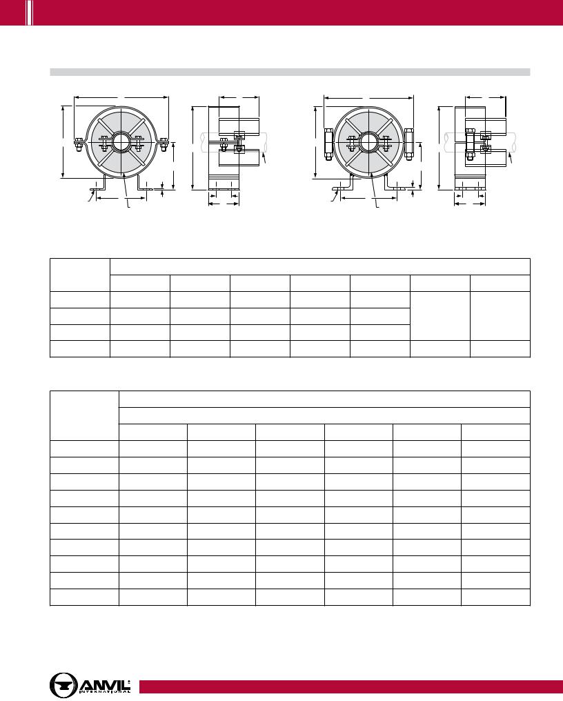
COPPER TUBING HANGERS 


Fig. CT-255 |
|
|
Copper Tubing Alignment Guide (cont.) |
|||||
|
A |
|
4 |
|
A |
|
|
4 |
|
C |
|
|
|
C |
|
|
|
B |
L |
|
|
B |
L |
|
|
|
|
C |
|
|
|
C |
|
||
|
|
|
|
|
|
|
||
|
D |
|
Tube |
|
|
D |
|
Tube |
|
T |
|
|
|
|
T |
|
|
H DIA |
E |
|
2 |
H DIA |
E |
|
|
2 |
4 HOLES |
J INSULATION THICKNESS |
|
4 |
4 HOLES |
|
J INSULATION THICKNESS |
|
4 |
|
|
|
|
|
||||
Copper Tubing Alignment Guide, Figure CT-255, Size A & B |
Copper Tubing Alignment Guide, Figure CT-255, Size C thru D |
|||||||
Guide |
|
|
|
Dimensions (in) |
|
|
|
|
|
|
|
|
|
|
|
|
|
Size No. |
A |
B |
C |
D |
|
E |
H |
T |
|
|
|||||||
A |
813⁄16 |
63⁄4 |
8 |
45⁄8 |
|
53⁄4 |
|
|
B |
1013⁄16 |
83⁄4 |
10 |
53⁄8 |
|
7 |
5⁄8 |
1⁄4 |
C |
135⁄16 |
111⁄4 |
127⁄16 |
65⁄8 |
|
73⁄4 |
|
|
D |
157⁄8 |
133⁄8 |
1413⁄16 |
715⁄16 |
|
93⁄4 |
3⁄4 |
3⁄8 |
|
|
|
|
Guide Size Number |
|
|
|
|
Tube Size |
|
|
|
Insulation Thickness (in) |
|
|
|
|
|
1 |
|
11⁄2 |
2 |
21⁄2 |
3 |
|
4 |
1⁄2 |
A |
|
A |
A |
A |
– |
|
– |
3⁄4 |
A |
|
A |
A |
A |
– |
|
– |
1 |
A |
|
A |
A |
A |
C |
|
C |
11⁄4 |
A |
|
A |
A |
C |
C |
|
C |
11⁄2 |
A |
|
A |
A |
C |
C |
|
C |
2 |
B |
|
B |
B |
B |
C |
|
C |
21⁄2 |
B |
|
B |
B |
B |
C |
|
C |
3 |
B |
|
B |
B |
B |
D |
|
D |
31⁄2 |
B |
|
B |
B |
D |
D |
|
D |
4 |
B |
|
B |
B |
D |
D |
|
D |
Table of |
Contents |
|
|
|
|
General |
Notes |
|
|
Copper Tubing |
Hangers |
|
|
Stainless Steel |
Hangers |
|
|
CPVC |
Pipe Hangers |
|
|
|
|
Pipe |
Rings |
|
|
Clevis |
Hangers |
|
|
|
|
Steel Pipe |
Clamps |
|
|
|
|
Socket |
Clamps |
|
|
|
|
Beam |
Clamps |
|
|
|
|
Structural |
Attachments |
|
|
|
|
Brackets |
|
|
|
|
|
Ceiling Plates & Flanges |
|
|
|
|
|
Concrete Inserts |
& Attachments |
|
|
|
|
Hanger |
Rods |
|
|
|
|
Rod |
Attachments |
|
|
|
|
Bolts, Nuts, |
Pins & U-Bolts |
|
|
www.anvilintl.com |
27 |
PH-11.11


 STAINLESS STEEL HANGERS
Fig. 137SS Stainless Steel U-Bolts
Size Range: 1⁄2" through 12"
Material: Stainless steel U-bolt and four finished hex nuts Finish: 304 stainless steel
Service: Recommended for support, or guide of heavy loads; often employed in power, process plant and marine service.
Approvals: Complies with Federal Specification A-A-1192A (Type 24), WW-H-171-E (Type 24), ANSI/MSS SP-69 and MSS SP-58 (Type 24). Ordering: Specify pipe size x rod size (e.g., 6 x 5⁄8), figure number and name. If hex nuts are not required, specify “without hex nuts”.
C
B 


 A
A
F
E
D
C
L
|
|
|
|
|
|
|
|
|
|
|
|
|
*When the combination of a normal load and |
|
FIG. 137SS: LOADS (LBS) • WEIGHTS (LBS) • DIMENSIONS (IN) |
||||||||||||
|
a side load occurs, a straight line interaction |
||||||||||||
|
|
|
|
|
|
|
|
|
|
|
|
|
|
|
Pipe |
Rod |
Max |
Max |
|
|
|
|
|
|
formula may be used to determine if the Fig. 137 |
||
|
Normal Load |
Side Load |
|
|
|
|
|
|
is still within the allowable stress range: |
||||
|
Size |
Size |
Wt. |
B |
C |
D |
E |
F |
Pn/Pna + Ps/Psa ≤ 1 |
||||
|
|
|
|
|
|||||||||
|
A |
450˚ F |
650˚ F |
450˚ F |
650˚ F |
|
|
|
|
|
|
||
|
|
|
|
|
|
|
|
Where: |
|||||
|
|
|
|
|
|
|
|
|
|||||
|
1⁄2 |
|
|
|
|
|
0.11 |
15⁄16 |
13⁄16 |
|
|
25⁄16 |
Pn = actual applied normal load; |
|
3⁄4 |
1⁄4 |
500 |
454 |
120 |
110 |
0.12 |
11⁄8 |
13⁄8 |
23⁄4 |
21⁄8 |
27⁄32 |
Pna = allowable normal load for the Fig. 137; |
|
1 |
|
|
|
|
|
0.12 |
13⁄8 |
15⁄8 |
|
23⁄32 |
Ps = actual applied side load; |
|
|
|
|
|
|
|
|
|
||||||
|
|
|
|
|
|
|
|
|
|
|
|
|
Psa = allowable side load for the Fig. 137 |
|
11⁄4 |
|
|
|
|
|
0.28 |
111⁄16 |
21⁄16 |
27⁄8 |
|
21⁄32 |
|
|
|
|
|
|
|
|
|
|
|
|
|
|
Nuts must be snug tight in installation to |
|
11⁄2 |
3⁄8 |
1,240 |
1,144 |
310 |
280 |
0.30 |
2 |
23⁄8 |
3 |
21⁄2 |
21⁄16 |
|
|
achieve side loads shown. |
||||||||||||
|
2 |
|
|
|
|
|
0.33 |
27⁄16 |
213⁄16 |
31⁄4 |
|||
|
|
|
|
|
|
|
|
|
|||||
|
21⁄2 |
|
|
|
|
|
0.73 |
215⁄16 |
37⁄16 |
33⁄4 |
|
25⁄16 |
|
|
3 |
1⁄2 |
2,300 |
2,070 |
570 |
515 |
0.78 |
39⁄16 |
41⁄16 |
4 |
3 |
21⁄4 |
|
|
4 |
0.90 |
49⁄16 |
51⁄16 |
41⁄2 |
|
|||||||
|
|
|
|
|
|
|
|
|
|||||
|
5 |
|
|
|
|
|
1.0 |
55⁄8 |
61⁄8 |
5 |
|
27⁄32 |
|
|
6 |
5⁄8 |
3,675 |
3,310 |
915 |
825 |
2.0 |
63⁄4 |
73⁄8 |
61⁄8 |
31⁄2 |
213⁄16 |
|
|
8 |
2.3 |
83⁄4 |
93⁄8 |
71⁄8 |
|
|||||||
|
|
|
|
|
|
|
|
|
|||||
|
10 |
3⁄4 |
5,490 |
4,940 |
1,370 |
1,235 |
4.9 |
107⁄8 |
115⁄8 |
83⁄8 |
4 |
3 |
|
|
12 |
7⁄8 |
8,400 |
7,560 |
2,115 |
1,905 |
7.7 |
127⁄8 |
133⁄4 |
95⁄8 |
31⁄4 |
|
|
|
|
|
|||||||||||
28 |
|
|
|
|
|
|
|
|
|
|
|
www.anvilintl.com |
|
PH-1.15
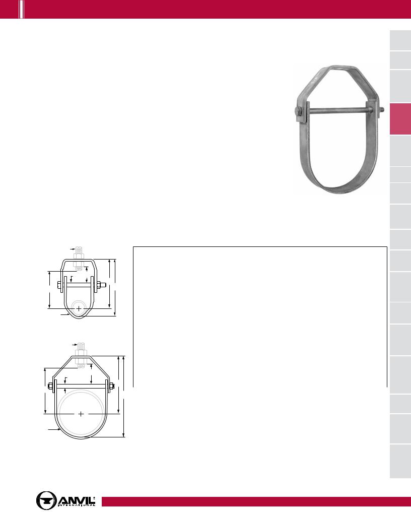
STAINLESS STEEL HANGERS 


Fig. 260SS |
Adjustable Clevis Hanger |
|
|
|
|
Size Range: 1⁄2" through 12" Material: 304 stainless steel
Service: Recommended for the suspension of stationary pipe lines.
Maximum Temperature: 650° F
Approvals: Complies with Federal Specification A-A-1192A (Type 1), WW-H-171-E (Type 1), ANSI/MSS SP-69 and MSS SP-58 (Type 1).
Installation: Hanger load nut above clevis must be tightened securely to assure proper hanger performance.
Adjustment: Vertical adjustment without removing pipe may be made from 3⁄8" through 5 1⁄8", varying with the size of clevis. Tighten upper nut after adjustment.
Features:
•Design has yoke on outside of lower U-strap so yoke cannot slide toward center of bolt, thus bending of bolt is minimized.
•Sizes 5" and up have rod and two nuts instead of bolt and nut; thread length on clevis rod is such that the thread locks the nuts in place, and threads are not in shear plane.
Ordering: Specify pipe size, figure number and name.
Notes: Punched forming holes may be present on certain sizes of this clevis hanger. These holes are
solely for the purpose of manufacturing, and do not effect the structural integrity or load carrying capacities of these hangers. For insulated line options without shields, see Figures 260 ISS and Figure 300. For ductile iron pipe sizes, see Figure 590SS.
Caution: When an oversize clevis is used, a pipe spacer or multispacer should be placed over clevis bolt to ensure that the lower U-strap will not move in on the bolt.
 A
A
G F
B
E 


 C
C
C
L
H
Pipe Size 1/2" to 3/4"
 A
A
F
G
B
E
C
C
L
H
FIG. 260SS: LOADS (LBS) • WEIGHTS (LBS) • DIMENSIONS (IN)
Pipe |
Max Load |
Weight |
Rod |
B |
C |
Rod Take |
Adjust. |
G |
H Width |
||
Size |
450˚ F |
650˚ F |
Size A |
Out E |
F |
Lower |
|||||
|
|
|
|
|
|
|
|
|
|
|
|
1⁄2 |
|
|
0.34 |
|
23⁄16 |
211⁄16 |
11⁄2 |
|
|
|
|
3⁄4 |
|
|
0.34 |
|
2 |
15⁄16 |
5⁄8 |
|
|
||
|
|
|
|
|
|
||||||
1 |
520 |
470 |
0.35 |
3⁄8 |
25⁄16 |
3 |
15⁄8 |
1⁄4 |
|
||
|
|
||||||||||
11⁄4 |
0.40 |
23⁄8 |
31⁄4 |
111⁄16 |
|
1 |
|||||
|
|
|
|
|
|||||||
11⁄2 |
|
|
0.45 |
|
213⁄16 |
313⁄16 |
21⁄8 |
7⁄8 |
|
||
|
|
|
|
|
|||||||
2 |
|
|
0.50 |
|
35⁄16 |
41⁄2 |
25⁄8 |
11⁄8 |
|
|
|
21⁄2 |
960 |
865 |
0.65 |
1⁄2 |
41⁄16 |
51⁄2 |
33⁄16 |
15⁄16 |
3⁄8 |
|
|
3 |
0.85 |
43⁄4 |
61⁄2 |
41⁄16 |
15⁄8 |
|
|||||
|
|
|
|
|
|||||||
4 |
1,215 |
1,095 |
1.51 |
5⁄8 |
59⁄16 |
713⁄16 |
41⁄2 |
111⁄16 |
3⁄8 |
|
|
5 |
1.70 |
69⁄16 |
815⁄16 |
51⁄2 |
115⁄16 |
13/16 |
|||||
|
|
|
|
||||||||
6 |
1,650 |
1,485 |
3.10 |
3⁄4 |
615⁄16 |
101⁄4 |
53⁄4 |
111⁄16 |
1⁄2 |
17/16 |
|
8 |
1,700 |
1,530 |
4.75 |
83⁄8 |
1211⁄16 |
73⁄16 |
2 |
||||
|
|
|
|||||||||
10 |
1,750 |
1,575 |
8.60 |
7⁄8 |
97⁄8 |
151⁄4 |
87⁄16 |
21⁄8 |
5⁄8 |
13/4 |
|
12 |
1,850 |
1,665 |
11.20 |
119⁄16 |
1715⁄16 |
101⁄8 |
213⁄16 |
2 |
|||
|
|
||||||||||
“Span” represents the maximum recommended distance between hangers on a continuous and straight run of horizontal standard weight steel pipe filled with water. In all cases, verify that chosen location of hangers does not subject hangers to a load greater than the maximum recommended load shown above. *Indicates that span represents the maximum span for water filled pipe as given in Table 1 of page 240.
Pipe Sizes 1" and Larger
Table of |
Contents |
General |
Notes |
Copper Tubing |
Hangers |
Stainless Steel |
Hangers |
CPVC |
Pipe Hangers |
Pipe |
Rings |
Clevis |
Hangers |
Steel Pipe |
Clamps |
Socket |
Clamps |
Beam |
Clamps |
Structural |
Attachments |
Brackets |
|
Ceiling Plates & Flanges |
|
Concrete Inserts |
& Attachments |
Hanger |
Rods |
Rod |
Attachments |
Bolts, Nuts, |
Pins & U-Bolts |
www.anvilintl.com |
29 |
PH-1.15


 STAINLESS STEEL HANGERS
Fig. 261SS |
Extension Pipe or Riser Clamp |
|
|
|
|
Size Range: 1⁄2" through 12" Material: 304 stainless steel
Service: For support of stationary steel pipe risers or conduit.
Maximum Temperature: 650° F
Approvals: Complies with Federal Specification A-A-1192A (Type 8) WW-H-171-E (Type 8), ANSI/MSS SP-69 and MSS SP-58 (Type 8). Installation: Clamp is fitted and bolted below a coupling, hub or welded lugs on steel pipe (2 lugs up to 3" pipe, 4 lugs up to 12" pipe). Bolt torques should be per industry standards (see page 248). Clamp is designed for standard steel pipe O.D. and this must be considered in sizing the riser for other types of piping.
Ordering: Specify pipe size, figure number, name and finish.
C
C
L
G
B
L
FIG. 261SS: LOADS (LBS) • WEIGHT (LBS) • DIMENSIONS (IN) • TORQUE (FT-LBS)
Pipe |
Max Load |
Lugs |
Weight |
L |
G |
B |
C |
Bolt |
Torque |
||
Size |
450˚ F |
650˚ F |
Width |
Diameter |
Values |
||||||
|
|
|
|
|
|||||||
1⁄2 - 3⁄4 |
185 |
165 |
|
1.1 |
87⁄8 |
|
27⁄8 |
|
|
|
|
1 |
210 |
190 |
|
1.1 |
|
31⁄8 |
3⁄8 |
3⁄8 |
21 |
||
|
|
|
|||||||||
11⁄4 |
|
1.6 |
10 |
|
31⁄2 |
||||||
|
|
|
|
|
|
|
|||||
11⁄2 |
255 |
230 |
2 |
1.6 |
101⁄4 |
1 |
37⁄8 |
|
|
|
|
2 |
340 |
305 |
|
1.7 |
41⁄4 |
|
|
|
|||
|
|
|
|
|
|
||||||
21⁄2 |
425 |
385 |
|
1.9 |
111⁄4 |
|
43⁄4 |
1⁄2 |
7⁄16 |
32 |
|
3 |
510 |
460 |
|
1.9 |
113⁄8 |
|
51⁄2 |
|
|
|
|
4 |
635 |
570 |
|
2.4 |
127⁄8 |
|
7 |
|
|
|
|
5 |
1,275 |
1,150 |
|
3.6 |
133⁄4 |
|
8 |
1⁄2 |
1⁄2 |
46 |
|
6 |
1,360 |
1,225 |
4 |
4.0 |
143⁄4 |
11⁄2 |
9 |
|
|
|
|
8 |
1,380 |
1,240 |
7.6 |
181⁄2 |
|
12 |
|
|
|
||
|
|
|
|
|
|||||||
10 |
1,800 |
16200 |
|
11.1 |
201⁄4 |
2 |
133⁄4 |
5⁄8 |
5⁄8 |
100 |
|
12 |
|
16.5 |
223⁄4 |
153⁄4 |
|
|
|
||||
|
|
|
|
|
|
|
|||||
30 |
www.anvilintl.com |
PH-1.15
 Loading...