

Page 1
Equipment: Vertical Contact Toaster Model VCT-2010
VCT-2010
Preventative Maintenance
Precaution:
During these checks, hot surfaces will be exposed.
Hazard Communication Standard (HCS) – The procedures on this card include the use of
chemical products. These chemical products will be highlighted with bold face let-
ters followed by the abbreviation (HCS) in the tools portion of the procedure. See
the Hazard Communication Standard (HCS) Manual for the appropriate Material Safety
Data Sheet(s) (MSDS).
PICTURES AND ADDITIONAL INFORMATION: In The Corresponding Chapter of Equipment Manual.
Daily Clean the VCT-2010
Tools: Clean white towels; three 1/6-size, 6-inch deep s/s pans; 1/6-size Cambro pan; Sanitizer;
Heavy Duty Multipurpose Sink Detergent or Powersink Detergent; Dishwashing sink.
Clean the VCT-2010
WARNING
Turn the power off, unplug the power cord, and allow
the unit to cool down 30 minutes before performing any
service or maintenance.
CAUTION
To prevent damage to the unit, do NOT use abrasive
cleaners on the Release Sheet or Silicone Belt.
CAUTION
Do NOT submerse the Butter Wheel Heated Base in
water. Do NOT wash this item with a water jet. Do NOT
spray cleansers directly on this item.
AT CLOSE
• Turn the unit OFF and unplug at the outlet. Allow unit to
cool.
• Remove the Butter Wheel and Pan. Pour the remaining
butter into a clean 1/6-sized Cambro pan. Cover with solid
lid and place on dry storage shelf. Mark side of pan “use
first”. NOTE: Only butter that is clear and debris-free can
be held over.
• Take Butter Wheel and Pan to the dishwashing sink. Hand
wash, rinse; then sanitize for a minimum of 60 seconds.
Allow to air dry. Return to service line; set aside for reassembly at open.
AT OPEN
• Make sure unit is off and unplugged at the outlet.
• Take Heat Shield off; then, remove Release Sheets.
• Fill a full-sized pan with hot Detergent Solution and place
both Release Sheets into pan to soak.
• Remove Butter Wheel Heated Base and clean on-line
when cleaning the Silicone Belt. Do NOT submerge.
• Remove Heat Shield, Front and Back Conveyor Covers,
and Bun Chute and take to dishwashing sink.
NOTE: Do NOT place parts into the powerwash sink.
• Pre-rinse, hand wash, rinse, and sanitize parts. Return
parts to service line.
• Fill a clean 1/6-sized, 6-inch deep s/s pan with hot
Detergent Solution; a second pan with clean rinse water;
and a third pan with Sanitizer Solution. Place a clean,
white towel in each pan and place near toaster.
• Wipe the Butter Pan Heater.
• Wipe both sides of the Silicone Belts (side facing out first)
with a clean, white towel and hot Detergent Solution. Rinse
with a clean, white towel and clean rinse water. Sanitize
using a clean, white towel and Sanitizer Solution.
• Rotate Belt around so the side facing inward is facing out,
exposing the soiled areas of the Silicone Belt. Wash, rinse,
and sanitize following the above step.
• Remove Release Sheets that have been soaking and take
to dishwashing sink. Hand wash, rinse, and sanitize both
sides. Return to service line.
• Wipe outside of toaster with a clean, white towel and hot
Detergent Solution.
• Reinstall the Bun Chute, Front and Back Conveyor Cover,
and Butter Wheel Heated Base.
• Install the Release Sheet. NOTE: Rotate sheet daily from
silver to black side.
• Install the Heat Shield. Plug unit in.
• Turn toaster and Butter Pan Holder ON 30 minutes prior to
opening.
NOTE: Line 2 toaster in modern restaurants can be
cleaned during slow periods of the day.
NOTE: Make sure the Heat Shield is activating the
Conveyor Safety Interlock Switch. The unit will not function unless the Heat Shield is in place and the Conveyor
Safety Interlock Switch is activated.
NOTE: Check the Release Sheet to make sure it is not
caught in the Conveyor. Additional Release Sheets can be
purchased under P/N 7000625 (3-Pack).
CAUTION
Failure to use Release Sheets may result in damage to
the unit and loss of warranty coverage.
© 2011 1 of 4 P/N 1011110 Rev. C 04/11
Page 2
Every 3-5 Weeks Replace the Release Sheet
INCORRECT
CORRECT
Tools: Heat-Resistant Gloves
VCT-2010
Preventative Maintenance
Replace the Release Sheet
IMPORTANT
Turn the power off, unplug the power cord and allow the
unit to cool down before proceeding.
NOTE: Depending on toaster usage and on how well it
is cleaned daily, the Release Sheet should last between
21–35 days. Additional Release Sheets can be purchased
under P/N 7000625 (3-Pack).
1. Turn the power off to the unit and the Butter Wheel
Heated Base. Unplug the power cord.
2. Put on heat-resistant gloves and remove the Heat
Shield.
3. Remove and discard the Release Sheet.
4. Lay a new Release Sheet on a clean, dry surface and
fold it in half lengthwise. Then gently crease it at the fold
using only your fingers.
5. Install the new Release Sheet by draping it over both sides
of the Platen with the crease centered on the Platen.
6. Reinstall the Heat Shield with the Release Sheet retainer
clips securely over the Release Sheet and Platen.
7. Plug in the power cord and test the unit before returning
it to service.
NOTE: Make sure the Heat Shield is activating the
Conveyor Safety Interlock Switch. The unit will not function
unless the Heat Shield is in place and the Conveyor Safety
Interlock Switch is activated.
NOTE: Check the Release Sheet to make sure it is not
caught in the Conveyor.
CAUTION
Failure to use Release Sheets may result in damage to
the unit and loss of warranty coverage.
Every 2-4 Months Replace the Silicone Belts
Tools: Heat-Resistant Gloves
Replace the Silicone Belts
NOTE: The Silicone Belts should last 2‒4 months.
Additional Silicone Belts may be purchased under P/N
7000626 (2-Pack).
1. Turn the power off, unplug the power cord, and allow the
unit to cool.
2. Unplug and remove the Butter Wheel Assembly, and
Heat Shield. Set the Bun Thickness Compression Knobs
to 6 and 6.
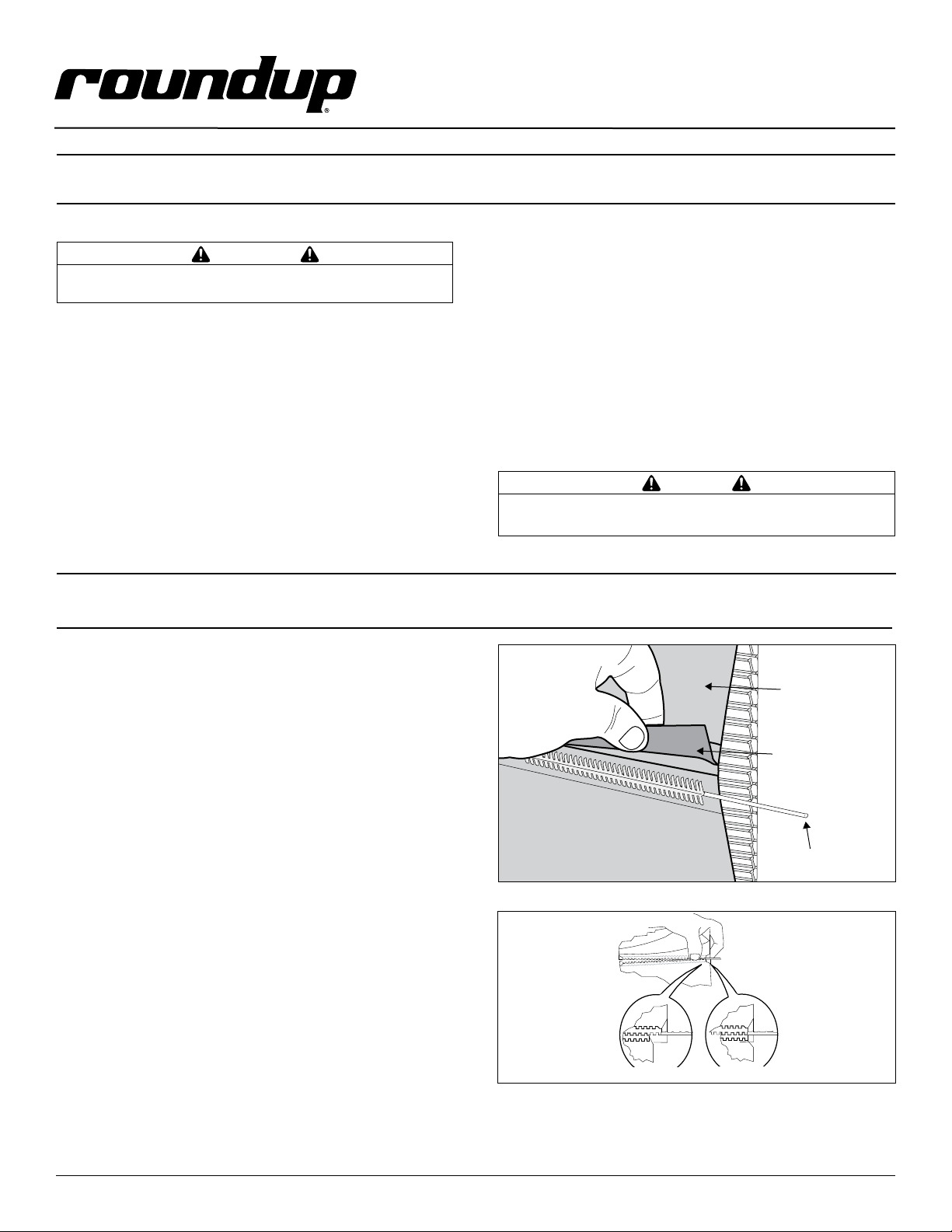
3. Remove both Conveyor Covers and pull the Silicone
Belt Pin from the zipper on the Silicone Belts (Figure 1).
4. Remove and discard the old Silicone Belts.
5. Clean both Conveyor Belt Chains just as you would
clean the Silicone Belts during Daily Cleaning.
6. Install the new Silicone Belts around the Conveyor Belt
Chains between the yellow Upper and Lower Support Rods.
The zipper flap should be exposed and hanging down
(Figure 1).
NOTE: Make sure the Silicone Belt is only wrapped around
the Conveyor Belt Chain.
7. Install the Silicone Belt Pins in the new Silicone Belts,
ensuring the ends are properly aligned (Figure 2).
8. Set the Bun Thickness Compression Knobs to 3 and 4.
9. Reinstall the Conveyor Covers, Heat Shield and Butter
Wheel Assembly.
10. Plug in the power cord and test the unit before returning
it to service.
© 2011 2 of 4 P/N 1011110 Rev. C 04/11
Figure 1. Removing Silicone Belt
Figure 2. Aligning Belt Teeth
Silicone
Belt
Silicone Belt
Flap (down)
Silicone
Belt Pin
Page 3

Every 3-6 Months Check the Conveyor Belt Chains
Tools: Heat-Resistant Gloves, Dime
VCT-2010
Preventative Maintenance
Check the Conveyor Belt Chains
NOTE: The Bun Thickness Compression Knobs must be
set to 6 and 6 prior to measuring, removing, or installing
the Conveyor Belt Chains.
MEASURING CONVEYOR BELT CHAINS
1. Remove the Butter Wheel Assembly, Bun Chute, and
Heat Shield. Set the Bun Thickness Compression Knobs
to 6 and 6.
2. Remove the front and rear Conveyor Covers and pull
the Silicone Belt Pin out of the zipper (Figure 1).
3. Pull the Conveyor Chain away from the edge of the
toaster.
NOTE: Do NOT pull too hard on the Conveyor Chain.
Pulling too hard will compress the top shaft, which will
make the gap between the frame and the chain seem
larger than it is.
4. Hold a U.S. Dime horizontally between the frame and
the chain (Figure 3).
5. If the gap is significantly wider than the coin, REMOVE
links as described.
6. Repeat on the opposite side of the toaster.
REMOVING CONVEYOR BELT CHAIN LINKS
1. Turn the power off, unplug the power cord, and allow the
unit to cool.
2. Remove the Butter Wheel Assembly, Bun Chute, and Heat
Shield. Set the Bun Thickness Compression Knobs to 6
and 6.
3. Remove the Conveyor Cover and pull the Silicone Belt
Pin out of the zipper.
4. Remove the Silicone Belt.
5. Locate the two Master Links as shown in Figure 4.
6. Remove the Master Link on both the left and right side
of the chain.
7. Remove one complete link from the chain.
8. Replace the Master Links on both the left and right side
of the chain. This connects the two ends of the chain
together.
NOTE: The ends of the hooks must point down.
9. Replace the Silicone Belt. Secure with Pin.
NOTE: Make sure the Conveyor Belt Chain and Silicone Belt
are installed between the yellow Upper and Lower Support
Rod.
10. Reinstall the Conveyor Covers, Butter Wheel Assembly,
Bun Chute, and Heat Shield.
11. Set the Bun Thickness Compression Knobs to 3 and 4.
12. Plug in the power cord and test the unit before returning
it to service.
© 2011 3 of 4 P/N 1011110 Rev. C 04/11
REPLACING THE CONVEYOR BELT CHAINS
1. Turn the unit off, unplug the power cord, and allow the
unit to cool.
2. Remove the Butter Wheel Assembly, Bun Chute, and Heat
Shield. Set the Compression Control Knobs to 6 and 6.
3. Remove the Conveyor Cover(s) and pull the Silicone Belt
Hinge Pin out of the zipper.
4. Pull the Conveyor Chain away from the edge of the
toaster. Remove the Silicone Belt.
5. Locate the two Master Links on the Conveyor Belt Chain
and remove both the left and the right Master Link.
6. Remove the existing Conveyor Belt Chains.
7. Place the new Conveyor Belt Chains on the top sprockets
with the hook ends down.
NOTE: The ends of the hooks must point down (Figure 4).
8. Wrap the Conveyor Belt Chain around the top and lower
sprockets and connect by replacing both the left and the
right Master Links.
9. Reinstall the Silicone Belts, Conveyor Covers, Butter
Wheel Assembly, Bun Chute, and Heat Shield.
10. Set the Bun Thickness Compression Knobs to 3 and 4.
11. Plug in the power cord and test the unit before returning
it to service.
Figure 3. Measuring Conveyor Belt Chain
Master Links
Figure 4. Removing Conveyor Belt Chain
Page 4

Every 3-6 Months Check the Roller Tensioners
Tools: Ruler, Adjustable Wrench
VCT-2010
Preventative Maintenance
Check the Roller Tensioners
MEASURING THE ROLLER TENSIONERS
1. Turn the power off, unplug the power cord, and allow the
unit to cool.
2. Remove the Butter Wheel Assembly and Heat Shield.
3. Remove the front and rear Conveyor Covers.
4. Measure the Roller Tensioner on both inner Conveyor
Covers (Figure 5).
5. The space between the inner Conveyor Cover and bottom
of the Tensioner wheel should be no larger than 1/2”.
6. Adjust or replace Tensioners as needed.
7. Reinstall the front and rear Conveyor Covers.
8. Reinstall the Heat Shield and Butter Wheel Assembly.
9. Plug in the power cord and test the unit before returning
it to service.
REPLACING/ADJUSTING THE ROLLER TENSIONERS
1. Remove the acorn nuts and old Roller Tensioner
Assembly.
2. Install the new Tensioner Assembly (Figure 6).
3. Make sure the spacers are placed inside the Tensioner
arm. The spacers allow the Tensioner to pivot freely.
4. Make sure there is 1/2” between the bottom of the
Tensioner wheel and the inside of the Conveyor Cover.
Inner Surface
of Conveyor cover
Figure 5. Measuring Roller Tensioner
Acorn Nuts
Roller
Tensioner
Assy.
Spacers
NOTE: Installation is the
same for both the Front
and Rear Conveyor Covers
Teflon
Tape
Figure 6. Roller Tensioner Assembly
Roller
Tensioner
Assy.
1/2 Inch
Rear
Conveyor
Cover
Heat Shield
Butter
Wheel
Butter
Pan
Butter Wheel
Heated Base
Conveyor
Cover (Front)
Silicone
Belt
Bun Chute
Release
Sheet
Conveyor
Chain
PROGRAM
LIGHTER
DARKER
Control Panel
and Power Switch
Belt
Roller
Tensioner
Conveyor
Cover (Rear)
Figure 7. VCT-2010 Components
© 2011 4 of 4 P/N 1011110 Rev. C 04/11
 Loading...