

Page 1

180 Kehoe Blvd.
Carol Stream, Illinois 60188 USA
VCT-2000 TECHNICAL MANUAL
LAST UPDATED 3-17-06
1060009 3/06 1
Page 2
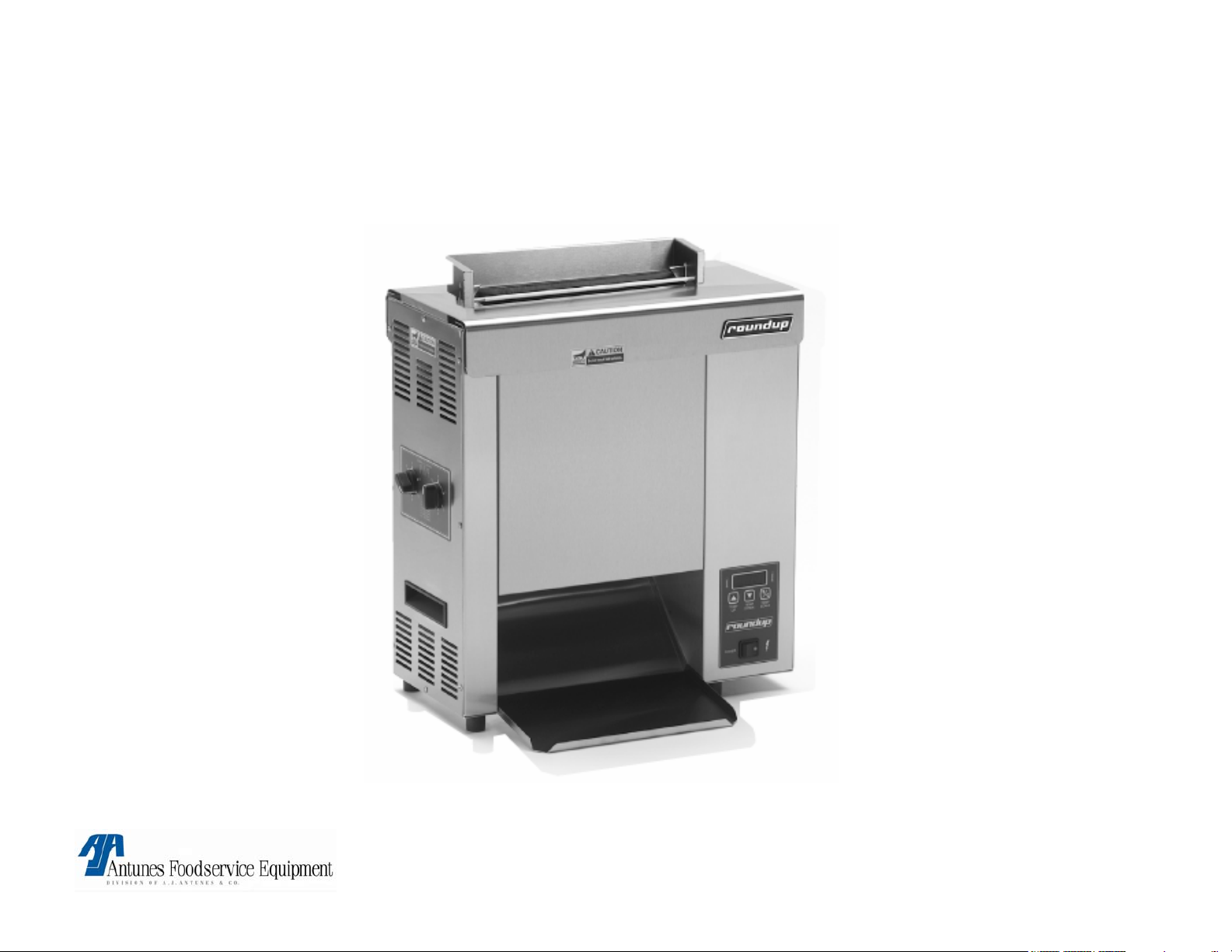
VCT-2000
VCT-2000 TECHNICAL MANUAL
LAST UPDATED 3-17-06
Unit shown with optional accessories
1060009 3/06 2
Page 3

VCT-2000
SECTION PAGE #
•Specifications 4
•Warnings 5
•Technical theory of operation
6
•Component description & functions 8
•Milli-volt chart 15
•Display Troubleshooting 16
•Troubleshooting 28
•Tools required 36
•Wiring diagram 37
•Parts testing & replacement 41
VCT-2000 TECHNICAL MANUAL
LAST UPDATED 3-17-06
1060009 3/06 3
Page 4
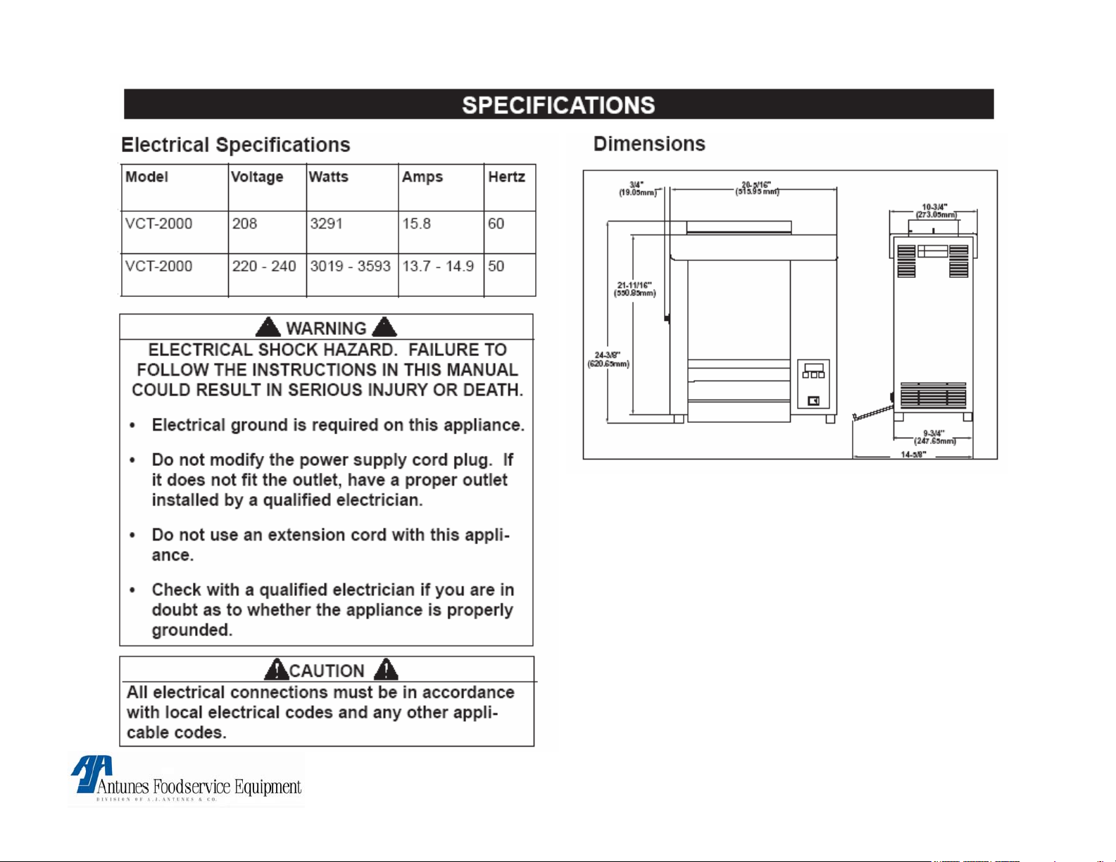
NOTE: Refer to spec label on rear of toaster for
electrical specifications.
VCT-2000 TECHNICAL MANUAL
LAST UPDATED 3-17-06
1060009 3/06 4
Page 5
WARNING
If the supply cord is damaged, it must be replaced by the
manufacturer or its service agent or a similarly qualified
person in order to avoid a hazard.
Do not use an extension cord with this
appliance.
WARNING
WARNINGWARNING
Do not modify the power supply cord plug if it does not fit
the outlet, have a proper outlet installed by a qualified
electrician.
Check with a qualified electrician if you are in
doubt whether the appliance is properly grounded
or Not.
WARNING
Do not clean this appliance with a water jet.
! ATTENTION ! ▲ WARNING ▲ ! ATTENTION !
To avoid possible injury and/or damage to the unit, inspection, test and repair of electrical equipment should be
performed by QUALIFIED SERVICE PERSONNEL. The unit should be unplugged when servicing, except when
electrical tests are required. Use extreme care during electrical circuit tests. Live circuits will be exposed.
VCT-2000 TECHNICAL MANUAL
LAST UPDATED 3-17-06
1060009 3/06 5
Page 6

VCT-2000 TECHNICAL THEORY OF OPERATION
Electrical/Temperature Theory
When the power switch is turned on, line voltage* flows to the top cooling fan & the primary side of the
step down transformer. The transformer’s secondary side supplies 12 VAC to the control board. Once
powered, & provided that the platen temperature (Platen Heating Circuit), or the auxiliary air
temperature (Auxiliary Air Heating Circuit) are below their setpoints, the control board calls for heat by
supplying 15-20 VDC** to terminals 3 (+) & 4 (-) on the platen relay or the auxiliary relay (Depending
which heating circuit is calling for heat). Once powered, the relay closes terminals 1 & 2, which allows
line voltage to flow to the platen, or the auxiliary heaters. As the platen or auxiliary heaters heat up, a
type “K” thermocouple monitors the internal platen temperature, while another type “K” (Located within
the front or rear belt wrap) monitors the auxiliary air temperature. As the heat continues to increase, so
does the thermocouple’s DC millivolts. Once the temperature approaches the setpoint, the
thermocouples are relaying certain DC millivolts to the control board (See Chart). The control board
receives these millivolts & proceeds to remove the 15-20 VDC** from the respective solid state relay,
since the heating circuit has now become satisfied. Then, relay terminals 1 & 2 open up, and the
heater(s) stops heating.
NOTE: It is normal for the VDC, VAC, & Amperage to pulse/fluctuate when the temperature is
at, or near the setpoint.
NOTE: The respective heating circuit will cycle on & off as needed, even at idle. This control
board can display several fault codes (See manual for further information). If the platen heater
circuit fails & the platen overheats, a manual resettable hi-limit thermostat will trip & open the
unit’s circuits, with the exception of the axial cooling fan at the top.
NOTE: If this condition should repeat, the root cause must be determined & corrected.
VCT-2000 TECHNICAL MANUAL
LAST UPDATED 3-17-06
1060009 3/06 6
Page 7

Electrical/Mechanical Theory
With the unit powered, & with all its covers properly in place, the top safety interlock switch is activated
& completes the line voltage circuit to the drive motor & auxiliary heaters.
NOTE: The drive motor runs & operates the conveyor system.
NOTE: The Auxiliary heaters will heat only if the auxiliary circuit is calling for heat, & the switch
is activated. With the unit rotating & up to temperature, the bun compression knobs (Located
on the side Panel) can be set to closely match the thickness of the crown or heel. When each
knob is adjusted, it rotates a horizontal cam, which in turn, pushes two vertical compression
plates towards, or away from the platen.
NOTE: The platen is covered by a teflon release sheet ***. Each front & rear rotating conveyor
chain is wrapped with a silicone belt that helps transfer heat to the skin side of the buns.
NOTE: The belt wraps *** are heated by the auxiliary heaters. It also pulls the buns down into
the unit. When the buns are fed from the top & begin to go through, their cut sides become
compressed against the teflon release sheet & platen & begin to toast. The buns will drop out
the bottom & onto a bun chute (Some Models). Or a heated base (Some Models).
* NOTE: European models are equipped with a line filter & an A/C isolator control board. The line filter will filter
line voltage noise. The A/C line isolator control board continuously monitors line voltage for the presence of a
50/60 Hz signal. Refer to wiring diagram for reference.
** NOTE: European models equipped with line filters & an A/C isolator control board supply approximately 1.0
to 2.0 VDC to each solid state relay (Not 15-20 VDC) during the call for heat. NOTE: It is normal for the VDC,
VAC, & Amperage to pulse/fluctuate when the temperature is at, or near the setpoint.
*** NOTE: Teflon Release Sheets & Conveyor belt wraps require daily cleaning & periodic replacement. Refer to
maintenance section in owners manual.
VCT-2000 TECHNICAL MANUAL
LAST UPDATED 3-17-06
1060009 3/06 7
Page 8

VCT-2000 Component Description & Function
Power Switch: Double Pole Single Throw, turns the supply voltage On or Off to the unit’s internal line voltage components.
NOTE: The built in led illuminates when line voltage is present into & out of the switch. If not lit, line voltage is not
present into or out of the switch.
Safety Interlock Switch: A Single Pole Single Throw (N.O) safety switch located at the top of the toaster. A constant
downward pressure on the switch by the top cover must be maintained to activate the switch. When depressed (activated)
by the top cover it completes the line voltage circuit to the drive motor & both auxiliary heaters. If the heat shield is missing
or not installed properly, the drive motor & both auxiliary heaters will not operate.
Stepdown Transformer: Consisting of 1 primary coil & 1 secondary coil, it steps down the incoming supply voltage to
approximately 12 VAC. The 12 VAC operates the control board.
Control Board : Operates & controls the temperature display, fault codes, platen & auxiliary heating circuits. This control
board displays several fault code messages. See “Fault Codes” in Operation Section.
Line Filter: An electrical component used only in Some European units. It filters supply voltage line noise.
A/C Line Isolator Control Board: An electrical component used only in Some European units. It monitors the presence of
a 50/60 Hz signal.
Platen SS Relay: Solid State, Single Pole Single Throw relay that is located within the electrical compartment. When its
input coil, (Terminals 3 + & 4 - ) is supplied VDC by the control board, it allows the line voltage contacts (Terminals 1 & 2) to
close. Once they close, line voltage is supplied to the main platen heater.
NOTE: SS relays should not be tested/diagnosed with an ohmmeter since this test is not reliable.
Testing/Diagnosing an SS relay should be conducted with the toaster & relay powered, and the use of a voltmeter.
If faulty, this relay will permanently fail open (No heat condition) or closed (Overheating condition). They do not fail
intermittently.
NOTE: Terminals 3 (+) & 4 (-) are polarity sensitive. The wiring can be inadvertently switched at the control board
or at the relay if either component is ever replaced. If so, VDC will still be present at the relay, but it will not
energize. Therefore, the platen will not heat up. Always verify per wiring diagram.
VCT-2000 TECHNICAL MANUAL
LAST UPDATED 3-17-06
1060009 3/06 8
Page 9

VCT-2000 Component Description & Function
Auxiliary SS Relay: Solid State, Single Pole Single Throw relay that is located within the electrical compartment.
When its input coil, (Terminals 3 + & 4 - ) is supplied VDC by the control board, it allows the line voltage contacts
(Terminals 1 & 2) to close. Once they close, line voltage is supplied to the 2 auxiliary air heaters. NOTE: SS relays
should not be tested/diagnosed with an ohmmeter since this test is not reliable. Testing/Diagnosing an SS
relay should be conducted with the toaster & relay powered, and the use of a voltmeter. If faulty, this relay
will permanently fail open (No heat condition) or closed (Overheating condition). They do not fail
intermittently. NOTE: Terminals 3 (+) & 4 (-) are polarity sensitive. The wiring can be inadvertently switched
at the control board or at the relay if either component is ever replaced. If so, VDC will still be present at the
relay, but it will not energize. Therefore, the auxiliary heaters will not heat up. Always verify per wiring
diagram.
Platen: Also known as a heating plate, it is a vertically mounted aluminum casting that consists of 1 permanently
integrated heating element. When powered, it generates the heat to toast, as well as to transfer the heat internally to
the cut side of the buns. Depending on model, it normally operates at a temperature range of approximately 550-600
F (287-315 C). NOTE: The platen must contain a teflon release sheet over it. Failure to install a teflon
release sheet on the platen will cause the buns to stick & possibly damage the platen’s aluminum surface.
Auxiliary Heaters: Also known as calrod heaters, there are two used. One is located within the front belt wrap &
conveyor chain area & the other is located within the rear belt wrap & conveyor chain area. Their purpose is to heat
the air within the belt wrap & conveyor chain area, which in turn, heats the belt wrap to approximately 340-400 F
(171-204 C). The hot belt wraps then transfer heat through the skin side of the buns as they are being pulled down
into the unit. This increases the buns internal temperature.
Platen Thermocouple: A type “K” consisting of 2 wires, Red (-) & Yellow (+). One end plugs onto the control board
terminal J1, & the other end is inserted into a hole in the platen. As it monitors the internal platen temperature, it
generates & relays DC millivolts to the control board (See Millivolt Chart). NOTE: At the control board, the
thermocouple connector plugs into 3 male pins. The center pin is positive (+) & MUST always align with the
yellow wire. The two outer pins are negative (-) & either one must align with the red wire.
VCT-2000 TECHNICAL MANUAL
LAST UPDATED 3-17-06
1060009 3/06 9
Page 10

VCT-2000 Component Description & Function
Auxiliary Thermocouple: A type “K” consisting of 2 wires, Red (-) & Yellow (+). One end plugs onto the control
board terminal J2, & the other end is inserted thr ough t he s tainless steel wall & secured to a bracket located within
the belt wrap & conveyor chain area. As it monitors the air temperature, it generates & relays DC millivolts to the
control board (See Millivolt Chart).
NOTE: At the control board, the thermocouple connector plugs into 3 male pins. The center pin is positive
(+) & MUST always align with the yellow wire. The two outer pins are negative (-) & either one must align
with the red wire.
Hi-Limit: A capillary tube style, normally closed temperature switch that monitors the internal platen temperature. If
the heating circuit fails & runs away, the hi-limit will trip between 680-720 F (360-382 C) & open the units line
voltage circuit components, with the exception of the top axial cooling fan.
NOTE: If the hi-limit trips, the reset button must be manually pressed to reset it. If at any time a hi-limit
trips, the root cause must be determined & corrected.
Drive Motor (Conveyor Motor): An electric motor integrated with a gear box. Provides the power & continuous
rotation of the main drive chain & sprockets within the electrical compartment. The spare red wire is only to be
used in areas (Countries) with 50 hertz only.
Axial Cooling Fan: An electrical cooling fan located at the top within the electrical compartment. Its main purpose
is to provide airflow, which in turn, maintains a cooler electrical compartment.
Idler Shafts: Two dummy shafts located at the top front & top rear of the unit. The shafts accommodate two
conveyor sprockets. They are driven by the lower drive shafts in conjunction with the conveyor belt chains &
sprockets.
NOTE: The idler shafts ends rotate within four Teflon bushings.
VCT-2000 TECHNICAL MANUAL
LAST UPDATED 3-17-06
1060009 3/06 10
Page 11

VCT-2000 Component Description & Function
Drive Shafts: Two shafts located at the bottom front & rear of the unit. They are driven by the drive chain, drive motor,
& several sprockets. The shafts accommodate two conveyor sprockets, one spacer, & one drive sprocket. NOTE: The
drive shaft ends (Towards the motor side) rotates within two steel ball bearings, while the opposite end rotates
within two Teflon bushings.
Drive Chain: Resembling a bicycle chain, it transfers the torque from the drive motor assembly to the two lower drive
shafts & sprockets.
Drive Sprockets: Located at 3 & 9 o’clock, they consist of a ½” bore & attach to the end of the two lower drive shafts.
Both drive sprockets are driven by the drive chain & drive motor assembly.
Idler Sprocket Assembly: A small ½” bore idler sprocket that is attached to a bronze sleeve bushing. Located at 10
o’clock, it allows for the drive chain to make an “S” turn between the idler sprocket & the 9 o’clock drive sprocket. This
allows the front conveyor chain to rotate & draw the buns into the toaster.
Motor Sprocket: A small 3/16” bore sprocket that attaches to the output shaft of the drive motor. It is the main sprocket
that provides the initial rotation.
Teflon Bushings: There are six bushings used per toaster. They are located at both ends of each of the two top idler
shafts & only on one end (Non Motor Side Only) of each of the two bottom drive shafts. They support the shafts & allow
for smooth rotation.
VCT-2000 TECHNICAL MANUAL
LAST UPDATED 3-17-06
1060009 3/06 11
Page 12

VCT-2000 Component Description & Function
Steel Ball Bearings: There are two steel ball bearings used per toaster. They are located at the end (Motor Side
Only) of the two bottom drive shafts. Ball bearings are used to support the added drive assembly weight & allow for
smooth rotation.
Conveyor Chain Sprockets: There are eight conveyor chain sprockets used per toaster. Two sprockets are
attached to each of the four shafts. These sprockets rotate the conveyor belt chains.
Conveyor Belt Chains: There are two conveyor belts chains used per toaster (Front & Rear). Each belt chain has
a silicone belt wrapped around it. The chain consists of a few ½” & many ¾” pitch links. As the belt chains & belt
wraps rotate simultaneously, they draw the buns into the toaster. NOTE: The chains will stretch over time with
normal wear & will require adjustment. See Parts Testing & Replacement Procedures.
Aluminum Spacers (Thrust): There are two spacers used per toaster. The spacer is located on each drive shaft
between the large conveyor chain sprocket (Closest to the motor side) & the electrical housing wall. Their purpose
is to limit the horizontal play of the drive shafts to 1/8” (3 mm). NOTE: With normal operation, the spacers will
wear & require replacement.
Tensioner Plate Assemblies: Resembling ski plates, there are four per toaster. They are positioned in pairs within
the front & rear conveyor belt chains. Each tensioner contains a white vertical teflon slide rail over its face (The
slide rails prevent metal to metal contact between tensioners & conveyor belt chains). The tensioners purpose is to
push out the conveyor belt chains, which in turn, compresses the buns up against the platen’s teflon release sheet
for toasting. NOTE: The tensioners protract & retract with the assistance of a conveyor cam. See conveyor
cam.
Conveyor Cams: There are two cams per toaster. Each cam is positioned horizontally & located behind each pair
of tensioner plate assemblies. One end of the cam is attached to a compression knob. When each compression
knob is set to a setting that closely matches the thickness of a bun’s crown & heel, the cam pushes out the
tensioner plates & conveyor belt chains, which in turn, compresses the buns up against the platen’s teflon release
sheet for toasting. NOTE: If the compression knob is set to 1/A, the cam is protracted to its maximum. If the
dial is set to 6/F, the cam is fully retracted.
VCT-2000 TECHNICAL MANUAL
LAST UPDATED 3-17-06
1060009 3/06 12
Page 13

VCT-2000 Component Description & Function
Compression Knobs: There are two compression knobs per toaster. Each knob is located at the end of each conveyor
cam. The knobs are to be set to a setting that closely matches the thickness of a bun’s crown & heel. The measurements
listed on the label correspond to the distance (gap) between the conveyor belt chains & platen. The buns become
compressed up against the platen’s teflon release sheet for toasting. NOTE: If the knob dial is set to 1/A, the cam is
protracted to its maximum. If the dial is set to 6/F, the cam is fully retracted.
Teflon Slide Rails: There are eight teflon slide rails used per toaster. Four of them are approximately 12” (305 mm) long
& located on the face of each tensioner plate assembly. The other four are approximately 3” (76 mm) long & each is
attached to a steel spring tensioner. They are located within the lower part of each conveyor belt chain area. The slide
rails prevent metal to metal contact between tensioners & conveyor belt chains & assist in guiding the conveyor belt
chains.
Roller Tensioners: There are two roller tensioners used per toaster & each is attached to the inner side of the conveyor
cover. They consist of a steel spring with roller wheel. Their purpose is to apply inward pressure to the conveyor belt
wraps & chains. This takes up the chain’s extra slack & maintains it at a constant tension. NOTE: The roller tensioners
must maintain a specific gap measurement. See Parts Testing & Replacement Procedures.
Release Sheets: There is one teflon sheet used per t oaster that consists of teflon material. It is placed over the platen &
provides a smooth surface for the buns to slide on to be toasted. NOTE: Release sheets are consumable items that
require periodic replacement. See Parts Testing & Replacement Procedures.
Silicone Belt Wraps: There are two silicone belt wraps used per toaster (Wrapped around each conveyor belt chain).
Their tacky surface assists in pulling the buns into the toaster as well as transferring heat to the skin side of the buns.
NOTE: The silicone belts wraps absorb heat generated by the auxiliary air heaters. Silicone Belt Wraps are
consumable items that require periodic replacement. See Parts Testing & Replacement Procedures.
Heated Base: (Some Models if equipped). It is a 35 watt aluminum foil heater that is adhered to the underside of the steel
base. Its purpose is to heat the steel base so that the buns can be maintained warm. NOTE: This heater is not
thermostatically controlled & is on continuously as long as the power switch is on.
VCT-2000 TECHNICAL MANUAL
LAST UPDATED 3-17-06
1060009 3/06 13
Page 14

VCT-2000 Component Description & Function
Top Heat Shield: When properly installed, it will shield excessive heat & depress (activate) the safety interlock switch.
NOTE: If the shield is missing or installed improperly, the safety interlock switch does not become depressed
(activated), therefore the conveyors, drive motor, & auxiliary heating elements will not operate.
Conveyor Cover Assemblies: There are two covers used per toaster. Each of which has a roller tensioner attached to
the inner side. The covers purpose is to shield the rotating conveyor belt wraps & chains. The roller tensioners purpose
is to apply inward pressure to the conveyor belt wraps & chains. This takes up the chain’s extra slack & maintains it at a
constant tension.
VCT-2000 TECHNICAL MANUAL
LAST UPDATED 3-17-06
1060009 3/06 14
Page 15
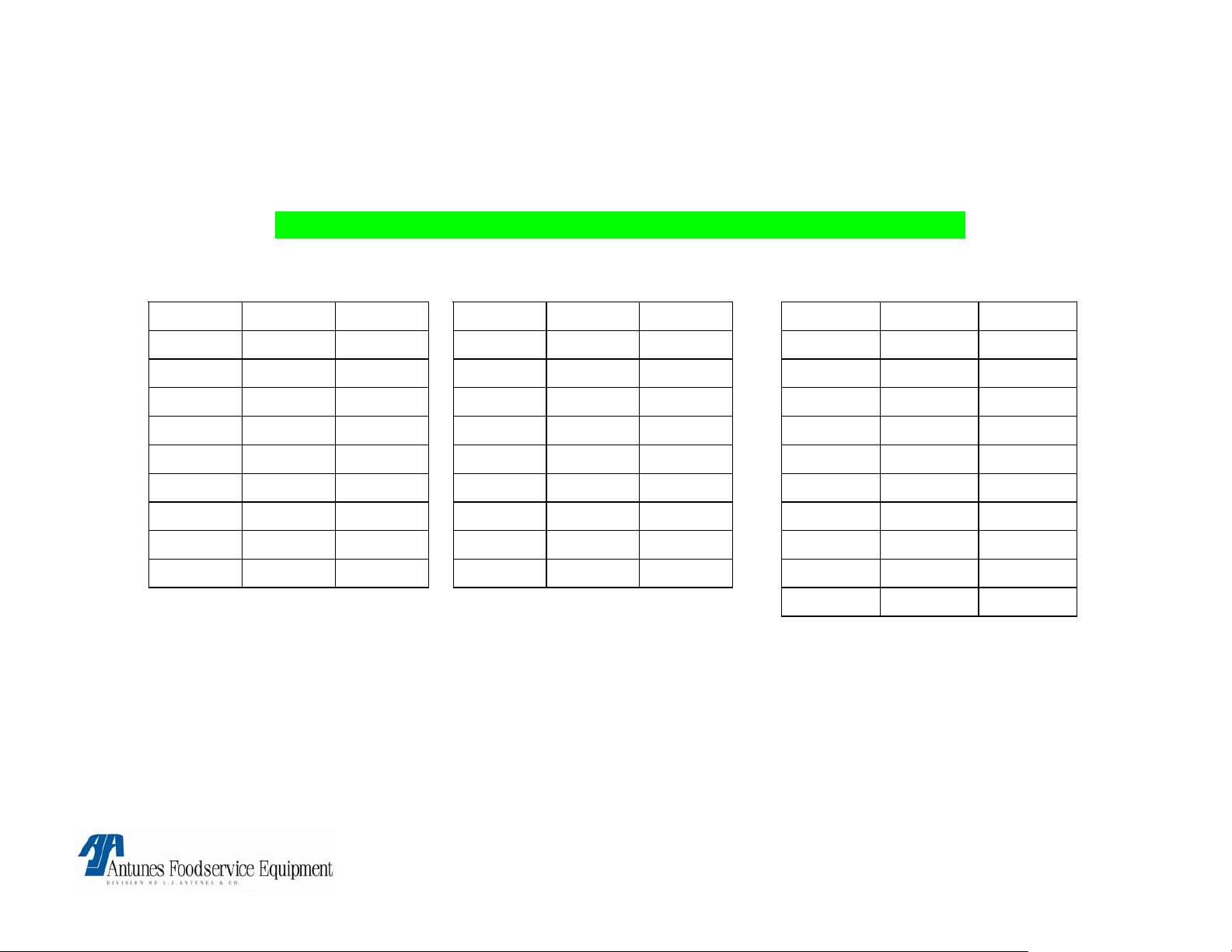
THERMOELECTRIC VOLTAGE IN MILLIVOLTS
TYPE “K” THERMOCOUPLE READINGS + OR – 1 MILLIVOLT
° F ° C MV ° F ° C MV ° F ° C MV
300 148.8 6.1
310 154.4 6.3
320 160.0 6.5
330 165.5 6.7
340 171.1 6.9
350 176.6 7.2
360 182.2 7.4
370 187.7 7.6
380 193.3 7.8
390 198.8 8.0
400 204.4 8.3
410 210.0 8.5
420 215.5 8.7
430 221.1 8.9
440 226.6 9.2
450 232.2 9.4
460 237.7 9.6
470 243.3 9.8
480 248.8 40.1
490 254.4 10.3
500 260.0 10.5
510 265.5 10.7
520 271.1 11.0
530 276.6 11.2
540 282.2 11.4
550 287.7 11.7
560 293.3 11.9
570 298.8 12.1
580 304.4 12.3
590 310.0 12.6
600 315.5 12.8
VCT-2000 TECHNICAL MANUAL
LAST UPDATED 3-17-06
1060009 3/06 15
Page 16
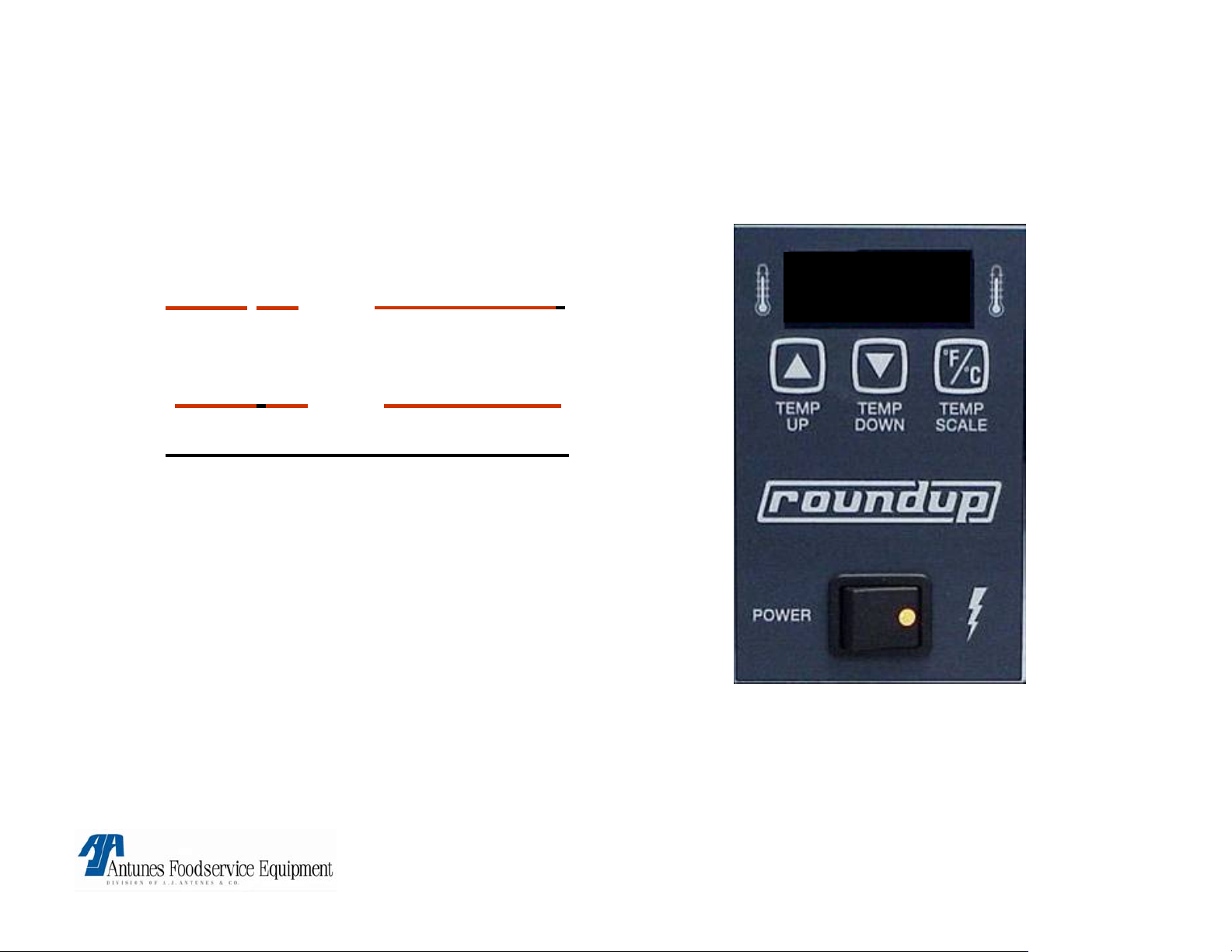
PLATEN & AUXILARY TEMPERATURE SET POINT
ADJUSTMENT
• Platen - press and hold
temp
up and temp down.
600° F
• Auxiliary - press and hold
temp up
and temp scale.
• Must hold for over 1 sec.
• Use up & down arrows to
make adjustments to
temperature.
• Changes must occur
within 5 seconds.
NOTE: To change from C° to F° or vice versa, Press & hold “Temp Scale” button for 5 seconds & release
NOTE: Common temperature settings are Platen 600° F (315°C) & Auxillary (400° F) (204°C).
NOTE: Temperature adjustments must be dine in 5 degree increments until the desired carmelization
(color) is achieved.
VCT-2000 TECHNICAL MANUAL
LAST UPDATED 3-17-06
1060009 3/06 16
Page 17
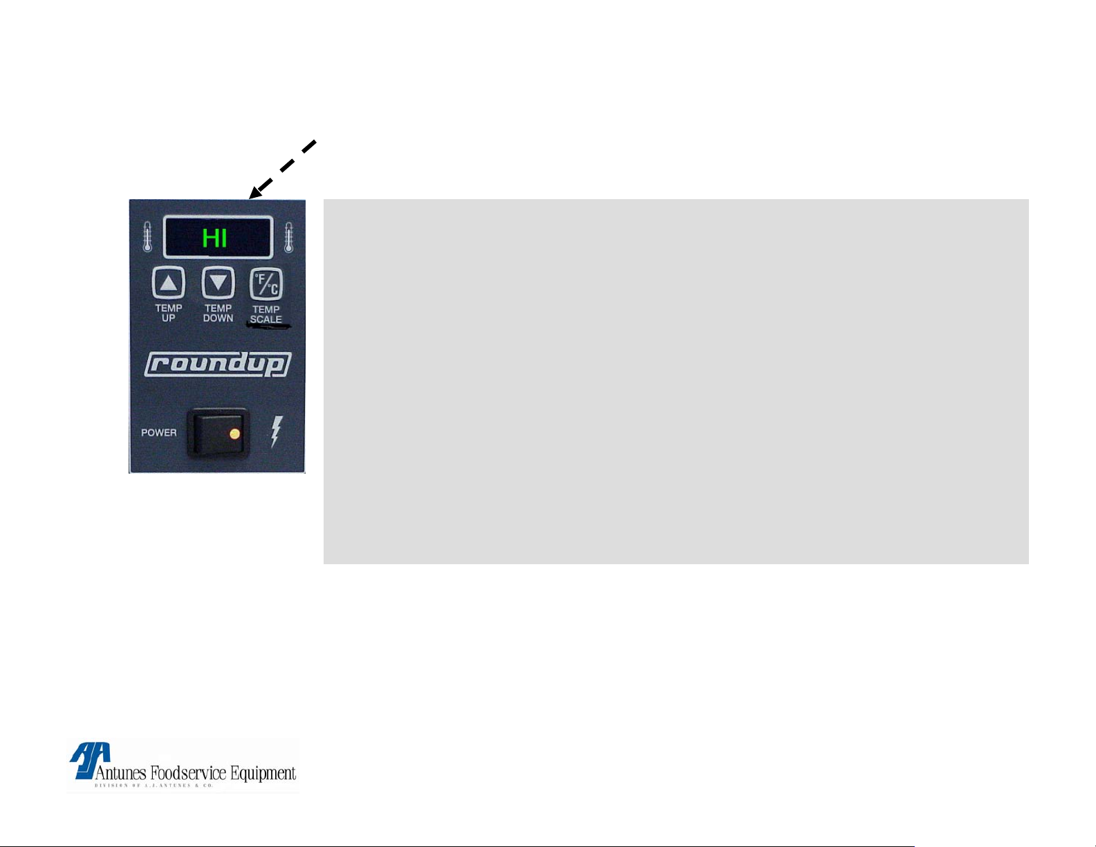
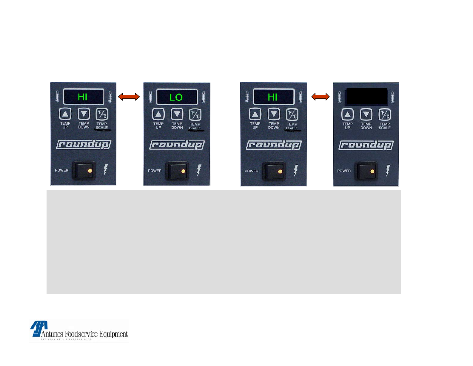
FLASHES HI “BUNS NOT TOASTING”
Possible Cause:
Loose (Platen) thermocouple
connection on Control board (J1A) or open Platen thermocouple
• Remove and reconnect connector. If still a problem, Check thermocouple
for continuity (2 to 3 OHM’S @ room temp) Between Yellow & Red wires &
replace if “open” or very high resistance.
If thermocouple checks o.k. Then faulty control board
• Circuit is miswired.
Verify per diagram.
Corrective action:
• Replace faulty component.
WARRANTY:
YES! IF IN WARRANTY PERIOD
VCT-2000 TECHNICAL MANUAL
LAST UPDATED 3-17-06
.
1060009 3/06 17
Page 18
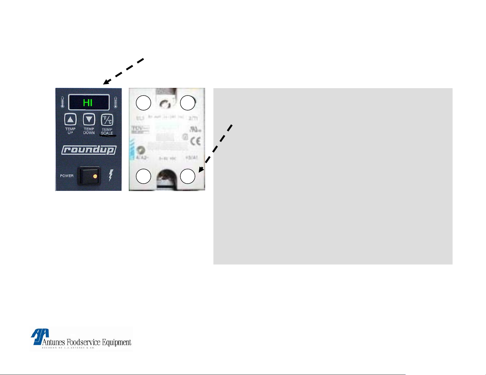
FLASHES HI “BUNS BURN”
Possible Cause:
1 2
4- 3+
NOTE: Old relays are
Black in color
• Relay:
Platen SS relay contacts 1&2 failed in closed position.
Remove red wire on relay terminal 3(+).
Is line voltage present across platen terminals ?
If yes, relay is faulty.
• Control Board:
Is 1 – 20vdc present on platen relay
terminals 3(+) & 4(-) ?
If yes, control board is faulty.
• Circuit is miswired:
verify per diagram.
Corrective action:
• Replace faulty component.
WARRANTY:
YES! IF IN WARRANTY PERIOD
VCT-2000 TECHNICAL MANUAL
LAST UPDATED 3-17-06
1060009 3/06 18
Page 19
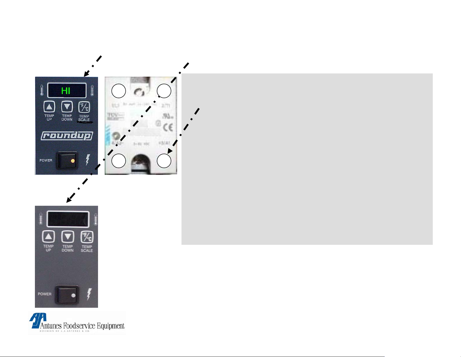
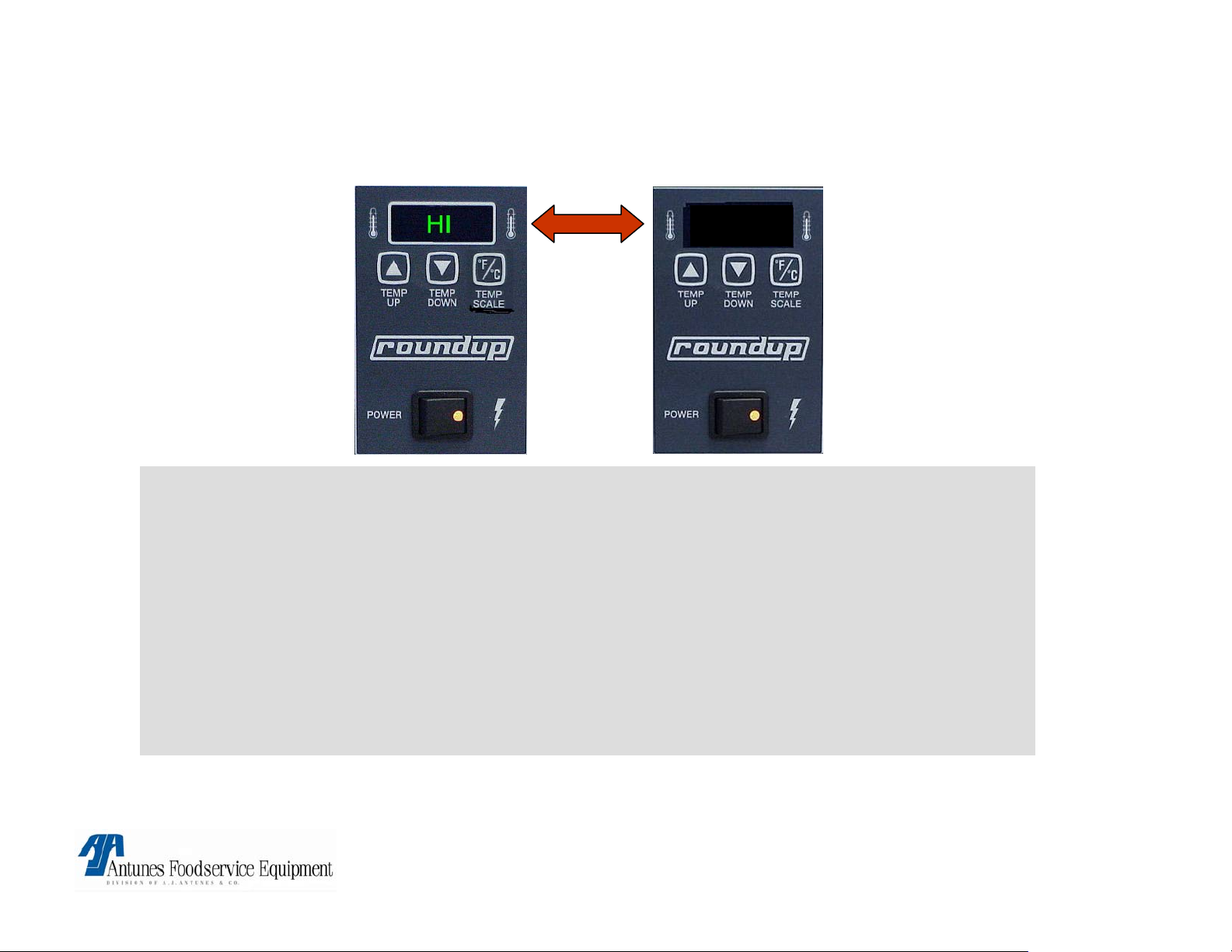
FLASHES HI “DISPLAY GOES BLANK”
Possible Cause:
1 2
3+4-
• Relay:
Platen SS relay contacts 1&2 failed in closed position.
Remove red wire on relay terminal 3(+).
Is line voltage present across platen terminals ?
If yes, relay is faulty.
• Control Board:
Is 1 – 20vdc present on platen relay terminals 3(+) & 4(-) ?
If yes, control board is faulty.
NOTE: Old relays are
Black in color
• Circuit is miswired:
verify per diagram.
Corrective action:
• Replace faulty component.
WARRANTY:
YES! IF IN WARRANTY PERIOD
VCT-2000 TECHNICAL MANUAL
LAST UPDATED 3-17-06
1060009 3/06 19
Page 20
CONTROL FLASHES HI & LO @ COLD START UP &
AFTER 20\30 MIN FLASHES HI & USE
USE
Possible cause:
Loose auxiliary thermocouple connection on control board. terminal (J2A).
• Remove and reconnect connector. If problem persists, check thermocouple for continuity
(2 – 3 Ohm’s @ room temp) Between Yellow & Red wires & replace if “open” or very high
resistance.
If thermocouple checks ok. Then faulty control board.
• Circuit is miswired: verify per diagram
Corrective action:
• Replace faulty component.
WARRANTY:
YES! IF IN WARRANTY PERIOD
VCT-2000 TECHNICAL MANUAL
LAST UPDATED 3-17-06
1060009 3/06 20
Page 21
FLASHES “HI & USE AFTER 20 TO 30 MIN
(NEVER FLASHED HI&LO @ COLD START UP).
USE
Possible cause:
Auxillary SS relay contacts 1&2 failed in closed position:
• Remove red wire on terminal 3(+), Is line voltage present across auxillary heater terminals
while drive motor is running ?
If yes relay is faulty.
• Circuit is miswired: verify per diagram.
• Control board:
If relay checks o.k. Control board is faulty.
Corrective action:
• Replace failed components.
WARRANTY:
YES! IF IN WARRANTY PERIOD
VCT-2000 TECHNICAL MANUAL
LAST UPDATED 3-17-06
1060009 3/06 21
Page 22
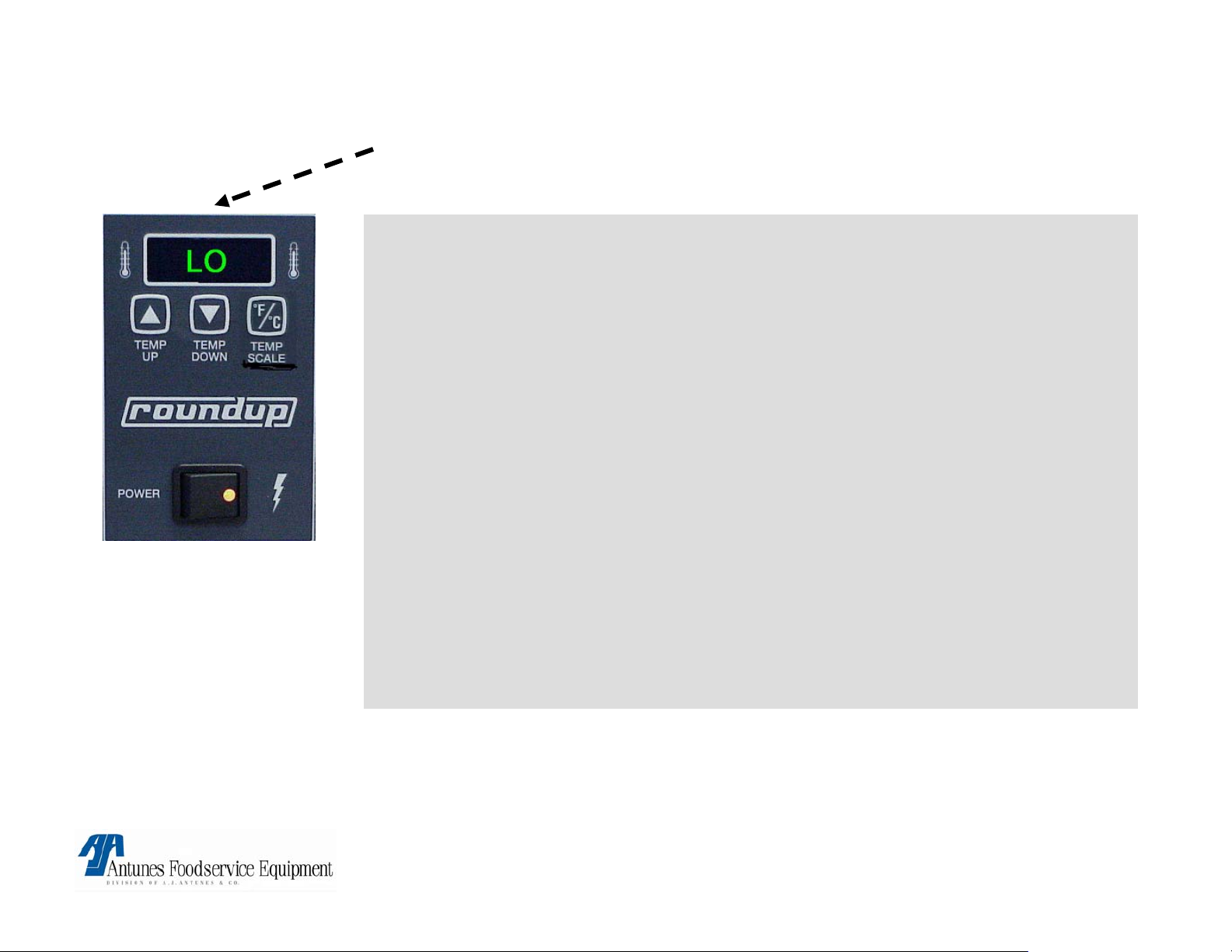
FLASHES LO “BUNS NOT TOASTING”
Possible Cause:
Platen not up to temp
allow 30 min for full warm up.
Platen SS. Relay contacts 1&2 are not closing.
Verify 15 to 20 VDC on relay terminals 3+ & 4-. If present, check for line
voltage across platen terminals. If not present faulty relay.
• Loose\burnt\open wiring in platen circuit.
Verify wiring for continuity & per wiring diagram.
• Circuit miswired.
Verify per diagram.
• Control board.
If above checks are ok. Faulty control board.
Corrective action:
• Replace faulty components.
WARRANTY:
YES! IF IN WARRANTY PERIOD
VCT-2000 TECHNICAL MANUAL
LAST UPDATED 3-17-06
1060009 3/06 22
Page 23
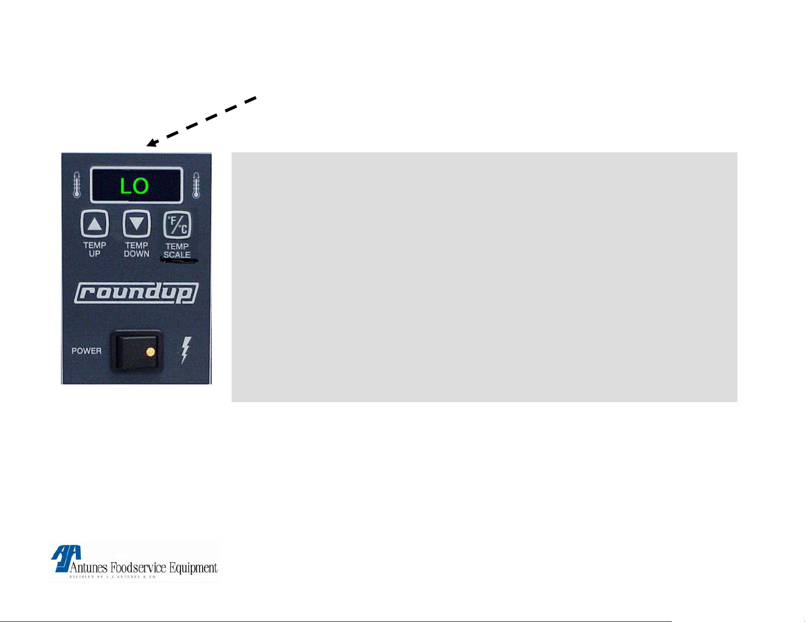
FLASHES LO “BUNS BURN”
Possible cause:
Grounded platen thermocouple or very low DC Millivolt output.
• Check Thermocouple for a ground using highest ohm scale.
If Red or Yellow wire shows a reading to ground, Then Faulty thermocouple.
• Obtain internal Platen temperatures & using Millivolt chart, determine if Thermocouple is
generating proper DC Millivolts at the indicated internal Platen temperature between Red
(-) & Yellow (+) wires.
If Millivolts generated do not correspond to Platen temperature, Then replace
thermocouple
Platen thermocouple leads are reversed on
connector:
• Verify yellow lead aligns with center pin & red aligns with either outer pin on control
board.
• Circuit is miswired: Verify per diagram
If above checks are ok. Faulty control board.
WARRANTY:
YES! IF IN WARRANTY PERIOD
VCT-2000 TECHNICAL MANUAL
LAST UPDATED 3-17-06
1060009 3/06 23
Page 24
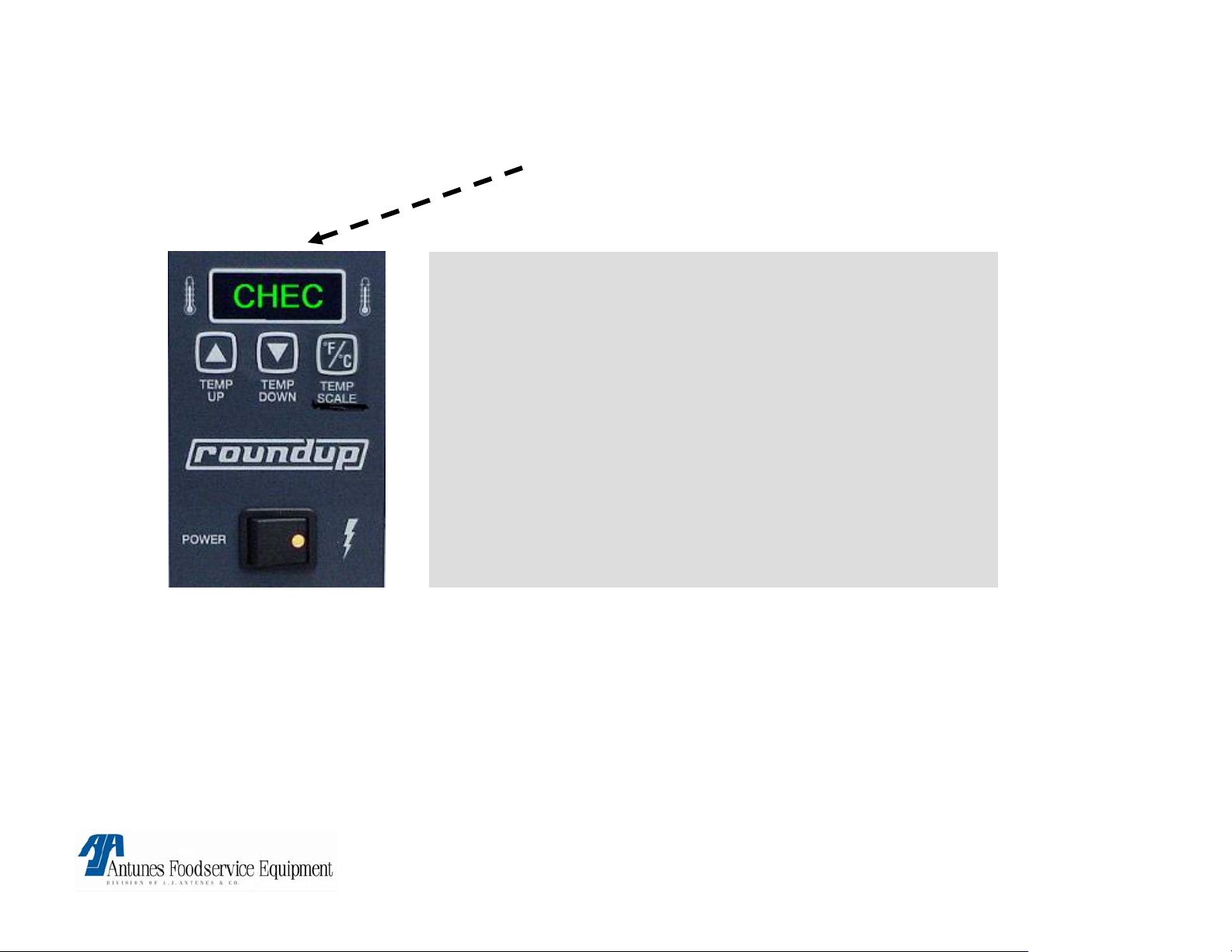
CONTROL FLASHES “CHEC”
Control Compartment temperature is above
140°F, 60°C
.
Possible Cause:
• Insufficient ventilation
• Failed top cooling fan.
• Failed control board.
Corrective action:
• Check for proper ventilation.
• Replace parts.
WARRANTY:
YES! IF IN WARRANTY PERIOD AND HAS PROPER VENTILATION
VCT-2000 TECHNICAL MANUAL
LAST UPDATED 3-17-06
1060009 3/06 24
Page 25

CONTROL FLASHES “PO”
Possible cause:
Transformer input below 180v.
• Verify line voltage of 180 to 240v @ transformer input (Blk & White wires)
• I f not, address line voltage issues with Licensed Electrician.
• Verify output voltage of transformer is Approximately 9 to 14 VAC
(Yellow wires)
If yes, faulty Control board.
Corrective action: Replace faulty parts.
WARRANTY:
YES! IF IN WARRANTY PERIOD AND HAS PROPER LINE VOLTAGE.
VCT-2000 TECHNICAL MANUAL
LAST UPDATED 3-17-06
1060009 3/06 25
Page 26

NO DISPLAY OR POWER
Possible cause:
• Power Switch or power cord.
• Tripped HI-limit or circuit Breaker (short to ground).
Corrective action:
• Check on\off switch for continuity.
• Check powercord for continuity and receptacle for line voltage.
• Reset Hi-limit.
• Reset circuit breaker.
• Check for shorts.
WARRANTY:
YES! IF IN WARRANTY PERIOD AND IS DUE TO A FAILED COMPONENT.
NO! IF RESETTING SWITCHES OR CIRCUIT BREAKERS OR IF DAMAGE
TO POWER CORD, RECEPTACLE OR SWITCH HAS OCCURED
VCT-2000 TECHNICAL MANUAL
LAST UPDATED 3-17-06
1060009 3/06 26
Page 27

FLASHES “PH”
See A/C Isolator control board in “parts testing & replacement procedures”.
NOTE: This applies only to units manufactured with electrical filters.
PH
VCT-2000 TECHNICAL MANUAL
LAST UPDATED 3-17-06
1060009 3/06 27
Page 28

CONVEYOR DOES NOT TURN
Possible causes:
• Safety switch on top is not activated by
heat shield.
• Conveyer belt chain has stretched &
skips.
• Roller tensioner is damaged or missing.
• Loose or derailed drive chain.
• Motor has failed
• Loose sprockets or setscrews.
• Safety interlock switch contacts are not
closing.
• Tripped hi-limit
WARRANTY:
YES! if within the warranty period and a component has failed.
Corrective action:
• Reinstall top heat shield & verify front & rear
covers are properly closed
Remove link or replace chain (See
maintenance section).
• Replace roller tensioner.
• Replace or tighten drive chain.
• If voltage across motor terminals & fan not
turning. Faulty motor.
• Verify set screw is tight on flat part of shaft.
• Isolate switch & verify continuity with button
pushed. If no continuity. Replace switch.
• Re-set hi-limit.
NO! if not in warranty period or do to improper handling or maintenance.
VCT-2000 TECHNICAL MANUAL
LAST UPDATED 3-17-06
1060009 3/06 28
Page 29

Conveyor Chain Binds or Stops or Stalls Intermittently & / or Drive
Chain (Bicycle Chain) Intermittently falls off sprockets.
Possible Cause(s): Corrective action:
• Bottom Drive Shaft(s) has/have
excessive horizontal play (Beyond 1/8”)
due to worn/missing aluminum thrust
spacers.
• Conveyor chains are too loose or too
tight.
• Drive Chain is too loose.
• Worn/Damaged Sprocket(s)
• Weak Drive Motor
• Safety Interlock Switch Locknut is loose
or Faulty Switch.
• Worn/Damaged Teflon &/or Steel Ball
Bearings.
• Refer to “Aluminum Spacers” in the “Parts Testing
& Replacement” section in this manual.
• Measure & adjust (If needed) Conveyor Chains per
Maintenance Section in owners manual.
• Readjust Drive Chain Tension to allow for ¼”
deflection play across the top.
• Refer to all sprocket illustrations in the “Parts
Testing & Replacement” section in this manual.
Check Sprocket Alignment.
• Refer to “Drive Motor” in the “Parts Testing &
Replacement” section in this manual.
• Refer to “Safety Interlock Switch” in the “Parts
Testing & Replacement” section in this manual.
• Refer to “Steel Ball Bearings” & “Teflon Bushings”
in the “Parts Testing & Replacement” section in this
• Internal Part/Object Interfering within
conveyor system.
VCT-2000 TECHNICAL MANUAL
LAST UPDATED 3-17-06
manual.
• Check for Interference & clear-up as necessary.
1060009 3/06 29
Page 30

BELT WRAP STOPS TURNING, CHAIN STILL TURNS
Possible cause:
• Dirty belts wraps.
• Dirty Conveyer chain.
WARRANTY: NO !
Corrective action:
• Clean underside of both belt wraps & both conveyor belt
chains with your approved detergent and wipe clean with
sanitizer.
• Replace both belt wraps if problem persists.
• Clean chain the same way & replace belt wraps per
maintenance section.
VCT-2000 TECHNICAL MANUAL
LAST UPDATED 3-17-06
1060009 3/06 30
Page 31

Buns Sticking & Burning at Entry
Possible Cause(s):
• Belt Wraps are too smooth & no longer
Tacky/Sticky
• Belt Wraps are not being cleaned
properly
• Belt Wraps are slipping around Conveyor
Belt Chains
• Teflon Release Sheets are too sticky & no
longer smooth
• Teflon Release Sheets are not being
properly cleaned.
• Conveyor Belt Chains skipping on lower
sprockets
• Buns are too thick
Corrective Action:
•
Replace Belt Wraps (Every 3-6 Months*) as
described in Owners Manual
• Clean Belt Wraps Daily as described in
Owners Manual
• Remove & clean Belt Wraps & Belt Chains
as described in Owners Manual.
• Replace Teflon Release Sheets (Every 4-6
weeks*) as described in Owners Manual
• Clean Teflon Sheets Daily as described in
Owners Manual
• Measure & adjust (If needed) Belt Chains as
per Owners Manual
• Match bun thickness with compression knob
thickness setting
* Pre-buttering / Pre-oiling buns before feeding them into the toaster leads to butter/oil accumulation on
the surface of the Teflon release sheet & Belt Wraps which may cause them to be replaced more often
than stated in the owners manual. This buildup is normal, however excessive buildup can lead to buns
sticking & burning. It is recommended that the Teflon release sheet be replaced or cleaned once every 6
hours of toaster operation. Dirty Teflon release sheets can be soaked in hot soapy water for later cleaning.
Continue to rotate Teflon release sheets, alternating between sides to maximize usage. Belt Wraps can be
wiped down through out the day using a sanitized towel.
Warranty: No!
VCT-2000 TECHNICAL MANUAL
LAST UPDATED 3-17-06
1060009 3/06 31
Page 32

BELT WRAPS TEARING IN CENTER
Possible cause:
• Missing or bent roller
tensioners.
Corrective action:
• If missing replace part.
• If bent reshape by bending or replace. Then re-test
the gap with a nickel (5 cents U.S.) to get proper
height.
WARRANTY: No!
VCT-2000 TECHNICAL MANUAL
LAST UPDATED 3-17-06
1060009 3/06 32
Page 33

SQUEALING, SQUEAKING NOISE
Possible cause(s):
• Excessive Carbon buildup on “White” slide
rails.
• Excessive buildup on Teflon bearing Inner
surface.
• Conveyer belt chains too tight (link
removed prematurely).
• Faulty bearings.
• Dry drive chain, and drive sprockets.
• Faulty drive motor.
Corrective action:
• Remove and clean belt chain & remove
Carbon buildup from all (8) White slide rails.
• Remove all 6 teflon bearings & remove
glaze on inner surface, clean shaft ends.
(use emory cloth). If problem persists, replace Teflon bearings.
• Measure belt chains per section in owners
manual & adjust if needed.
• Replace faulty bearings. (Steel ball bearings and Teflon
bearings).
• Lube drive chain & sprockets.
• Replace drive motor.
WARRANTY:
YES! IF IN WARRANTY PERIOD AND DUE TO COMPONENT FAILURE
NO! IF NOT IN WARRANTY PERIOD OR LACK OF MAINTENANCE (lubrication).
VCT-2000 TECHNICAL MANUAL
LAST UPDATED 3-17-06
1060009 3/06 33
Page 34

BELTS WRAPS DO NOT FIT
Possible Cause:
• Flap is not hanging down.
• Using incorrect or damaged belt wraps.
• Belt installed over yellow rods.
WARRANTY: NO !
Corrective action:
• Belt wraps installed incorrectly, or upside
down.
• Verify Belt Wrap is installed around
conveyor chain only.
VCT-2000 TECHNICAL MANUAL
LAST UPDATED 3-17-06
1060009 3/06 34
Page 35

VCT-2000 TECHNICAL MANUAL
LAST UPDATED 3-17-06
1060009 3/06 35
Page 36

TOOLS REQUIRED.
• Volt \ Ohm Meter. (Digital or Analog).
• Flat blade screwdriver ¼ “.
• Flat blade screw starter.
• Phillips head screwdriver.
• Needle nose pliers.
• Lube-it8 P\N 2140152.
• Amprobe. (Digital or Analog).
• Change 15 cents U.S. (1- dime 1-nickel)
VCT-2000 TECHNICAL MANUAL
LAST UPDATED 3-17-06
1060009 3/06 36
Page 37

UNITS WITHOUT ELECTRICAL FILTERS
VCT-2000 TECHNICAL MANUAL
LAST UPDATED 3-17-06
1060009 3/06 37
Page 38

UNITS WITHOUT ELECTRICAL FILTERS
VCT-2000 TECHNICAL MANUAL
LAST UPDATED 3-17-06
1060009 3/06 38
Page 39

UNITS WITH ELECTRICAL FILTERS
VCT-2000 TECHNICAL MANUAL
LAST UPDATED 3-17-06
1060009 3/06 39
Page 40

UNITS WITH ELECTRICAL FILTERS
VCT-2000 TECHNICAL MANUAL
LAST UPDATED 3-17-06
1060009 3/06 40
Page 41

VCT-2000
Parts Testing & Replacement Procedures
VCT-2000 TECHNICAL MANUAL
LAST UPDATED 3-17-06
1060009 3/06 41
Page 42

TESTING POWER SWITCH
See Power Switch under “Component Description & Function” before proceeding
Disconnect wires to isolate switch.
Turn switch to the “On” position. Verify continuity across
terminals 1 & 2, then 4 & 5. Next, turn switch to the “Off”
position. Reading should now be infinity.
Replace if fails test.
.
5
4
2
1
Replacement Procedures
Disconnect power switch wires (Mark for reinstallation).
Squeeze locking tabs inward & push switch out towards front of unit.
Snap new switch into place until flush.
Reinstall wiring onto switch.
Test unit for proper operation.
VCT-2000 TECHNICAL MANUAL
LAST UPDATED 3-17-06
1060009 3/06 42
Page 43

TESTING SAFETY INTERLOCK SWITCH
See Safety Interlock Switch under “Component Description & Function” before proceeding.
Disconnect wires to isolate switch.
Press & hold switch in. Verify continuity across
both terminals. Next, release switch. Reading
should now be infinity.
Replace if fails test.
Note: Verify lock nut is tight
Locknut
Replacement Procedures
Disconnect switch wires.
Remove lock nut & switch.
Install new switch & secure.
Reinstall wiring onto switch.
Test unit for operation
VCT-2000 TECHNICAL MANUAL
LAST UPDATED 3-17-06
1060009 3/06 43
Page 44

TESTING STEPDOWN TRANSFORMER
See Stepdown Transformer under “Component Description & Function” before proceeding.
Is line voltage VAC present across the two “Blk & White
Line input wires” ? If yes, is 9-14 VAC present across the
two “Yellow Load output wires” ?
If no, replace transformer.
Replacement Procedures
Disconnect transformer wires (Mark for
reinstallation).
Remove the two mounting screws.
Install new transformer & secure with screws.
Reinstall the wiring onto transformer.
Test unit for proper operation.
VCT-2000 TECHNICAL MANUAL
LAST UPDATED 3-17-06
1060009 3/06 44
Page 45

TESTING CONTROL BOARD
See Control Board under “Component Description & Function” before proceeding.
Control Board must be tested while powered up
(See Technical Theory of Operation).
Check for proper VAC/VDC input & output.
Replace if it fails any of its functions.
Replacement Procedures
Disconnect control board wiring & unplug both
thermocouples (Mark for reinst allation).
Remove the mounting nuts & control board.
Install new control board & secure with the nuts.
Reinstall the wiring & plug both thermocouples onto
control board.
Allow unit to heat up 20 minutes.
Test unit for proper operation.
VCT-2000 TECHNICAL MANUAL
LAST UPDATED 3-17-06
1060009 3/06 45
Page 46

TESTING PLATEN SS RELAY
See Platen SS Relay under “Component Description & Function” before proceeding.
To determine if relay contacts are stuck closed
(Platen overheating):
Disconnect RED wire from relay terminal 3 (+).
Clamp an amp meter onto the black wire at relay terminal
1 or 2. Is there any amp draw?
If yes, replace relay.
To determine if relay contacts are stuck open (Platen
not heating):
Ensure the control board & relays are wired per the wiring
diagram.
Is VDC present at relay terminals 3 (+) & 4 (-)? If yes, is
line voltage present across relay terminals 1 & 2?
If yes, replace relay.
This Platen relay configuration is used only with units with electrical
filters. The VDC input varies between 1-2 VDC
1 2
4- 3+
Replacement Procedures
Disconnect the relay wiring (Mark for reinstallation).
Remove the mounting screws & relay.
Install new relay & secure with screws.
Reinstall wiring onto relay.
Test unit for proper operation.
VCT-2000 TECHNICAL MANUAL
LAST UPDATED 3-17-06
1060009 3/06 46
Page 47

TESTING AUXILIARY SS RELAY
See Auxiliary SS Relay under “Component Description & Function” before proceeding.
To determine if relay contacts are stuck closed (Auxiliary
Heaters overheating):
Disconnect RED wire from relay terminal 3 (+).
Clamp an amp meter onto the black wire at relay terminal 1 or 2.
Is there any amp draw?
If yes, replace relay.
To determine if relay contacts are stuck open (Auxiliary
Heaters not heating):
Ensure the control board & relays are wired per the wiring
diagram & the drive motor is operating.
Is VDC present at relay terminals 3 (+) & 4 (-)? If yes, is line
voltage present across relay terminals 1 & 2?
If yes, replace relay.
This Auxilary relay configuration is used only with units with
electrical filters. The VDC input varies between 1-2 VDC
1
4-
2
3+
Replacement Procedures
Disconnect the relay wiring (Mark for
reinstallation).
Remove the mounting screws & relay.
Install new relay & secure with screws.
Reinstall wiring onto relay.
Test unit for proper operation.
VCT-2000 TECHNICAL MANUAL
LAST UPDATED 3-17-06
1060009 3/06 47
Page 48

TESTING LINE FILTER (IF EQUIPPED)
See Line Filter under “Component Description & Function” before proceeding.
Is line voltage VAC present across the two “Line” input
terminals? If yes, is line voltage VAC present across
the two “Load” input terminals?
If no, replace line filter.
Replacement Procedures
Remove line filter wiring (Mark for reinstallation).
Remove mounting screws & line filter.
Install new line filter & secure with screws.
Reinstall wiring onto line filter.
Allow unit to heat up 20 minutes.
Test unit for proper operation.
VCT-2000 TECHNICAL MANUAL
LAST UPDATED 3-17-06
1060009 3/06 48
Page 49

TESTING A/C LINE ISOLATOR CONTROL BOARD (IF EQUIPPED)
See A/C Line Isolator Control Board under “Component Description & Function” before proceeding.
Does display flash “PH”? If yes, is the drive motor
operating? If yes, proceed & unplug the wiring harness that
connects the main control board to the A/C line isolator
control board & check it for continuity. Is continuity
present? If yes, reconnect the wiring harness. Does display
still flash “PH”? If yes
replace the A/C Line Isolator Control Board.
Note: If drive motor is not operating, verify the heat shield
lid is activating the safety interlock switch. Check switch for
continuity.
Replacement Procedures
Disconnect control board wiring. (Mark for reinstallation).
Remove the mounting screws & control board.
Install new control board & secure with the screws.
Reinstall the wiring & onto control board.
Allow unit to heat up 20 minutes.
Test unit for proper operation.
VCT-2000 TECHNICAL MANUAL
LAST UPDATED 3-17-06
1060009 3/06 49
Page 50

See Platen under “Component Description & Function” before proceeding.
Disconnect wires to isolate the platen Verify
continuity, Check from each calrod element to
ground using an ohmmeter set to at least a 20M
scale. Reading should be infinity.
Replace if fails either test.
TESTING PLATEN
Replacement Procedures
Refer to Instruction Sheet # 1010741 for step by step
replacement instructions.
NOTE: This sheet is also supplied in platen kit.
VCT-2000 TECHNICAL MANUAL
LAST UPDATED 3-17-06
NOTE: This picture shown without relays for clarity
purposes,
1060009 3/06 50
Page 51

TESTING AUXILIARY HEATERS
See Auxiliary Heaters under “Component Description & Function” before proceeding.
Disconnect wires to isolate auxiliary heater & check for continuity.
Check from each calrod terminal to ground using an ohmmeter set
to at least a 20M scale. Reading should be infinity.
Replace if fails either test.
Replacement Procedures
Remove silicone belt wrap.
Remove conveyor belt chain.
Disconnect auxiliary heater wiring.
Remove heater retainer clip.
Dismount heater from suppor t bracket & remove heater.
Follow the above procedures in reverse order for
reinstallation. Test unit for proper operation.
VCT-2000 TECHNICAL MANUAL
LAST UPDATED 3-17-06
1060009 3/06 51
Page 52

TESTING PLATEN TYPE ”K” THERMOCOUPLE
See Platen Thermocouple under “Component Description & Function” before proceeding.
Test platen thermocouple for continuity: Unplug thermocouple
from control board to isolate it.
At room temperature, verify 2-3 ohms across red & yellow wire.
Replace if fails test.
To determine if Platen is “overheating” or “under heating” due
to a faulty platen thermocouple: Preheat unit for 30 minutes then
monitor the platen’s surface, or internal temperature. Next, unplug
the thermocouple from the control board. Set your VOM to the VDC
scale, 50-200 MV (millivolt) range. Using the provided millivolt chart,
determine if the thermocouple is generating the proper DC millivolts
(+/- 1.0 millivolt) at the indicated temperature.
Quick Tip: If the unit is under heating, the DC millivolts being
generated will be much higher than what they should. If the unit is
overheating, the DC millivolts being generated will be much lower
than what they should be.
Replace if fails test.
Replacement Procedures Unplug platen thermocouple
from control board.
Loosen retainer bracket screw & remove from hole.
Install new platen thermocouple & secure to platen &
control board.
Test unit for proper operation.
VCT-2000 TECHNICAL MANUAL
LAST UPDATED 3-17-06
1060009 3/06 52
Page 53

TESTING AUXILIARY TYPE ”K” THERMOCOUPLE
See Auxiliary Thermocouple under “Component Description & Function” before proceeding.
Test auxiliary thermocouple for continuity: Unplug
thermocouple from control board to isolate it.
At room temperature, verify 2-3 ohms across red & yellow wire.
Replace if fails test.
To determine if auxiliary heaters are “overheating” or
“underheating” the air due to a faulty auxiliary thermocouple:
Preheat unit for 30 minutes then monitor the air temperature near
the auxiliary thermocouple. Next, unplug the thermocouple from
the control board. Set your VOM to the VDC scale, 50-200 MV
(millivolt) range. Using the provided millivolt chart, determine if the
thermocouple is generating the proper DC millivolts (+/- 1.0
millivolt) at the indicated temperature.
Quick Tip: If the unit is under heating, the DC millivolts being
generated will be much higher than what they should. If the unit is
overheating, the DC millivolts being generated will be much lower
than what they should be.
Replace if fails test.
Replacement Procedures
Remove the front silicone belt wrap.
Remove conveyor belt chain.
Remove thermocouple from mounting bracket by sliding it out of
the retainer clip.
Unplug thermocouple from control board.
Follow the above procedures in reverse order for reinstallation.
Test unit for proper operation.
VCT-2000 TECHNICAL MANUAL
LAST UPDATED 3-17-06
1060009 3/06 53
Page 54

TESTING HI-LIMIT
See Hi-limit under “Component Description & Function” before proceeding.
Test Hi-Limit for continuity: Disconnect wires to isolate hi-limit.
Verify continuity across the terminals. If no continuity, depress the
black reset button. If still no continuity, replace Hi-Limit.
To determine if hi-limit is tripping prematurely: Monitor the
platen’s surface or internal temperature.
Does hi-limit trip below 680 F (360 C)? If yes, replace hi-limit.
To determine if hi-limit is tripping too late, or not at all:
Temporarily short relay terminals 1 & 2 together
(This simulates an overheating condition).
Monitor the platen’s surface or internal temperature.
Does the temperature exceed 700 F (382 C)? Is the platen still
drawing amperage? If yes, replace hi-limit.
NOTE: Reinstall any removed wiring to their original terminals.
Replacement Procedures
Disconnect hi-limit wires.
Remove lock nut & dismount the hi-limit ceramic body.
Remove capillary tubing bracket & pull tubing out of platen hole.
Install new hi-limit & secure with bracket & lock nut.
Reinstall wiring onto hi-limit.
Test unit for proper operation.
VCT-2000 TECHNICAL MANUAL
LAST UPDATED 3-17-06
1060009 3/06 54
Page 55

TESTING DRIVE MOTOR (CONVEYOR MOTOR)
See Drive Motor (Conveyor Motor) under “Component Description & Function” before proceeding.
Test motor coil for continuity: Disconnect wires
to isolate motor coil & verify continuity from
terminals COM to 60 HZ & from COM to 50 HZ.
Replace if fails test.
Testing gearbox: Does the fan blade shaft turn? If
yes, does the gearbox shaft turn? If no, or, if the
shaft can easily be stopped under load, replace
drive motor.
Replacement Procedures
Refer to Instruction Sheet # 1010750 for step by step
replacement instructions.
NOTE: This sheet is also supplied in drive motor kit.
Test unit for proper operation
VCT-2000 TECHNICAL MANUAL
LAST UPDATED 3-17-06
1060009 3/06 55
Page 56

TESTING AXIAL COOLING FAN
See Axial Cooling Fan under “Component Description & Function” before proceeding
Test fan coil for continuity: Disconnect wires to isolate
fan coil & verify continuity across its terminals.
Replace if fails test.
.
Replacement procedures
Disconnect fan coil wires.
Remove the top fan duct bracket.
Remove the four fan mounting screws & fan.
Follow the above procedures in reverse order for reinstallation.
Test unit for proper operation & air flow.
VCT-2000 TECHNICAL MANUAL
LAST UPDATED 3-17-06
1060009 3/06 56
Page 57

TESTING IDLER SHAFTS
See Idler Shafts under “Component Description & Function” before proceeding
The idler shafts are generally trouble free however, if the shafts, teflon
bushings, &/or sprockets are physically damaged or worn, they must be
replaced.
Testing for worn teflon bushings: Do the ends of the idler shafts have
significant vertical play? If yes,
replace the teflon bushings.
Replacement Procedures
Remove the silicone belt wrap.
Remove conveyor belt chain.
Loosen the two conveyor sprocket setscrews.
NOTE: The shafts have two predrilled dimples to position the setscrews for proper spacing.
Remove the teflon bushing steel retainer & then slide shaft out.
Follow the above procedures in reverse order for reinstallation.
Test unit for proper operation.
VCT-2000 TECHNICAL MANUAL
LAST UPDATED 3-17-06
1060009 3/06 57
Page 58

TESTING DRIVE SHAFTS
See Drive Shafts under “Component Description & Function” before proceeding.
The drive shafts are generally trouble free
however, if the drive shafts, aluminum
spacers, teflon bushings, steel ball bearings,
&/or sprockets are physically damaged or
worn, they must be replaced.
Testing for worn teflon bushings & steel
ball bearings: Do the ends of the drive shafts
have significant vertical play? If yes, replace
the teflon bushings or steel ball bearings.
Testing for worn aluminum(thrust)
spacers: Do the drive shafts have lateral play
beyond a 1/8” (3 mm)? If yes, replace the
aluminum spacers.
Replacement Procedures
If necessary, remove the bracket &/or any components that will simplify the removal of
the shaft towards the drive motor side.
NOTE: Removal of the drive sprocket is not required unless the drive sprocket
&/or shaft are being replaced.
Remove the drive motor assembly & drive chain.
Remove the silicone belt wrap.
Remove conveyor belt chain.
Loosen the two conveyor sprocket setscrews.
NOTE: The shafts have two predrilled dimples to position the setscrews for
proper spacing.
Slide the shaft out towards the drive motor side.
Follow the above procedures in reverse order for reinstallation.
Test unit for proper operation.
SPACER
CHECK FOR SIDE TO SIDE PLAY
VCT-2000 TECHNICAL MANUAL
LAST UPDATED 3-17-06
1060009 3/06 58
Page 59

TESTING DRIVE CHAIN
See Drive Chain under “Component Description & Function” before proceeding.
The drive chain is generally trouble free however, if it is
physically damaged or worn, it must be replaced.
Proper drive chain play is 1/4” (6 mm) between the motor
drive sprocket located at 6 o’clock & the drive sprocket
located at 9 o’clock. Tension is adjusted by loosening the
four drive motor mounting screws & pushing the drive
motor downward. Once the proper tension is obtained,
continue to maintain the downward pressure on the drive
motor as you retighten the four screws.
Replacement Procedures
If necessary, remove the bracket &/or any components that will
simplify the removal & installation of the drive chain.
Remove the drive motor assembly.
Remove the drive chain from the sprockets.
Follow the above procedures in reverse order for reinstallation &
verify proper drive chain tension.
Test unit for proper operation.
VCT-2000 TECHNICAL MANUAL
LAST UPDATED 3-17-06
1060009 3/06 59
Page 60

TESTING DRIVE SPROCKETS
See Drive Sprockets under “Component Description & Function” before proceeding.
With normal use, the drive sprocket’s teeth may
begin to wear out. If the sprockets are physically
damaged or worn, they must be replaced.
Proper drive chain play is 1/4” (6 mm) between
the motor drive sprocket located at 6 o’clock & the
drive sprocket located at 9 o’clock. Tension is
adjusted by loosening the four drive motor
mounting screws & pushing the drive motor
downward. Once the proper tension is obtained,
continue to maintain the downward pressure on
the drive motor as you retighten the four screws.
NOTE: Drive sprocket size & teeth vary. Refer to
owners manual for specific sprocket types. Type
shown are for illustration purposes only.
Replacement Procedures
If necessary, remove the bracket &/or any components that will simplify the removal & installation
of the drive sprockets.
Remove the drive motor assembly.
Remove the drive chain from the sprockets.
Using the proper size hex key, loosen the sprocket setscrew.
NOTE: Make note of the sprocket’s position for proper realignment of new sprockets.
Follow the above procedures in reverse order for reinstallation & verify proper drive chain tension.
Test unit for proper operation.
DRIVE SPROCKETS
VCT-2000 TECHNICAL MANUAL
LAST UPDATED 3-17-06
1060009 3/06 60
Page 61

TESTING IDLER SPROCKET ASSEMBLY
See Idler Sprocket under “Component Description & Function” before proceeding.
With normal use, the idler sprocket teeth may begin to wear out. If
the idler sprocket is physically damaged or worn, it must be
replaced.
Proper drive chain play is 1/4” (6 mm) between the motor drive
sprocket located at 6 o’clock & the drive sprocket located at 9
o’clock. Tension is adjusted by loosening the four drive motor
mounting screws & pushing the drive motor downward. Once the
proper tension is obtained, continue to maintain the downward
pressure on the drive motor as you retighten the four screws.
Replacement Procedures
If necessary, remove the bracket &/or any components that will simplify the removal & installation of the idler
sprocket assembly.
Remove the drive motor assembly.
Remove the drive chain from the sprockets.
Using the proper size hex key, loosen the 9 o’clock drive sprocket setscrew & remove drive sprocket.
NOTE: Make note of the sprocket’s position for proper realignment of new sprockets.
Remove the idler sprocket bracket.
Remove the idler sprocket assembly from the bracket.
Follow the above procedures in reverse order for reinstallation & verify proper drive chain tension.
Test unit for proper operation.
VCT-2000 TECHNICAL MANUAL
LAST UPDATED 3-17-06
1060009 3/06 61
Page 62

TESTING MOTOR SPROCKET
See Motor Sprocket under “Component Description & Function” before proceeding.
With normal use, the motor sprocket teeth may begin to wear out.
If the motor sprocket is physically damaged or worn, it must be
replaced.
Proper drive chain play is 1/4” (6 mm) between the motor drive
sprocket located at 6 o’clock & the drive sprocket located at 9
o’clock. Tension is adjusted by loosening the four drive motor
mounting screws & pushing the drive motor downward. Once the
proper tension is obtained, continue to maintain the downward
pressure on the drive motor as you retighten the four screws.
NOTE: Drive sprocket size & teeth vary.
Refer to owners manual for specific
sprocket types. Type shown are for
illustration purposes only.
MOTOR SROCKET
Replacement Procedures If necessary, remove the bracket &/or any components that will simplify the removal & installation of
the motor sprocket.
Remove the drive motor assembly.
Using the proper size hex key, loosen the motor sprocket setscrew & remove motor sprocket.
NOTE: Make note of the sprocket’s position for proper realignment of new sprocket. Refer to instruction sheet
#1010750
Follow the above procedures in reverse order for reinstallation & verify proper drive chain tension.
Test unit for proper operation.
VCT-2000 TECHNICAL MANUAL
LAST UPDATED 3-17-06
1060009 3/06 62
Page 63

TESTING TEFLON BUSHINGS
See Teflon Bushings under “Component Description & Function” before proceeding.
The teflon bushings are generally troublefree however, with
normal use, they may begin to wear out &/or accumulate
residue. If they are physically damaged or worn, they must
be replaced.
Testing for worn teflon bushings: Do both ends of the
idler shafts & the non motor side of the drive shafts have
significant vertical play? If yes, replace the teflon bushings.
Replacement Procedures
Refer to Instruction Sheet # 1010810 for step by step procedures.
NOTE: This sheet is supplied with the teflon bushing replacement kit.
VCT-2000 TECHNICAL MANUAL
LAST UPDATED 3-17-06
1060009 3/06 63
Page 64

TESTING STEEL BALL BEARINGS
See Steel Ball Bearings under “Component Description & Function” before proceeding.
The steel ball bearings are generally trouble free however, with normal
use, they may begin to wear out. If they are damaged or worn, they must
be replaced.
Testing for worn steel ball bearings: Do the drive shafts (Drive motor
side only) have significant vertical play? If yes, replace the steel ball
bearings.
Proper drive chain play is 1/4” (6 mm) between the motor drive sprocket
located at 6 o’clock & the drive sprocket located at 9 o’clock. Tension is
adjusted by loosening the four drive motor mounting screws & pushing
the drive motor downward. Once the proper tension is obtained,
continue to main tain the downward pressure on the drive motor as you
retighten the four screws.
Replacement Procedures
If necessary, remove the bracket &/or any components that will simplify
the removal & installation of the steel ball bearings.
Remove the drive motor assembly.
Remove the drive chain from the sprockets.
Using the proper size hex key, loosen the drive sprocket setscrew & remove
sprocket(s). NOTE: Make note of the sprocket’s position for proper
realignment.
If replacing the steel ball bearing at 3 o’clock, remove the steel retainer &
then the bearing.
If replacing the steel ball bearing at 9 o’clock, you must first remove the
idler sprocket with bracket assembly, & then the bearing.
Follow the above procedures in reverse order for reinstallation & verify proper
drive chain tension. Test unit for proper operation.
VCT-2000 TECHNICAL MANUAL
LAST UPDATED 3-17-06
1060009 3/06 64
Page 65

TESTING CONVEYOR CHAIN SPROCKETS
See Conveyor Chain Sprockets under “Component Description & Function” before proceeding.
With normal use, the conveyor chain sprockets may begin to wear out. If they are
physically damaged or worn, they must be replaced.
Proper drive chain play is 1/4” (6 mm) between the motor drive sprocket located at 6
o’clock & the drive sprocket located at 9 o’clock. Tension is adjusted by loosening the
four drive motor mounting screws & pushing the drive motor downward. Once the
proper tension is obtained, continue to maintain the downward pressure on the drive
motor as you retighten the four screws.
Replacement Procedures
To replace the conveyor chain sprockets located on the top idler shafts:
Remove end panels
Remove the silicone belt wrap.
Remove conveyor belt chain.
Loosen the two conveyor sprocket setscrews.
NOTE: The shafts have two predrilled dimples to position the setscrews for proper
spacing.
Remove one teflon bushing steel retainer & then slide shaft out.
Follow the above procedures in reverse order for reinstallation.
Test unit for proper operation.
VCT-2000 TECHNICAL MANUAL
LAST UPDATED 3-17-06
1060009 3/06 65
Page 66

TESTING CONVEYOR CHAIN SPROCKETS
( PICTURES ARE ON THE FOLLOWING PAGE)
To replace the conveyor chain sprockets located on the bottom drive shafts:
If necessary, remove the bracket &/or any components that will simplify the removal & installation of
the drive shaft.
Remove the drive motor assembly.
Remove the drive chain from the sprockets.
NOTE: Removal of the drive sprocket is not required unless the drive sprocket &/or shaft are
being replaced.
Remove the silicone belt wrap.
Remove conveyor belt chain.
Loosen the two conveyor sprocket setscrews.
NOTE: The shafts have two predrilled dimples to position the setscrews for proper spacing.
Slide the shaft out towards the drive motor side.
Follow the above procedures in reverse order for reinstallation & verify proper drive chain tension.
Test unit for proper operation.
VCT-2000 TECHNICAL MANUAL
LAST UPDATED 3-17-06
1060009 3/06 66
Page 67

VCT-2000 TECHNICAL MANUAL
LAST UPDATED 3-17-06
1060009 3/06 67
Page 68

TESTING CONVEYOR BELT CHAINS
See Conveyor Belt Chains under “Component Description & Function” before proceeding
The conveyor belt chains are generally trouble free however,
with normal use, they chain stretches & will require a small ½”
link removed. If the chain is physically damaged or worn, they
must be replaced.
Test for a stretched chain per maintenance section in the
owners manual.
.
Test & replacement Procedure
Remove the silicone belt wrap.
Perform the chain measurement test using a dime
Set the compression knobs to the widest setting 6 & 6
In the middle of the chain pull the chain away from the toaster and place a dime “perpendicular” to the chassis
between the chassis and the chain if the gap is wider than a dime remove a link either a ½ or ¾ inch link
Replace chain “curved end facing down”
Replace belt wraps
Test unit for operation
VCT-2000 TECHNICAL MANUAL
LAST UPDATED 3-17-06
1060009 3/06 68
Page 69

TESTING ALUMINUM SPACERS
See Aluminum Spacers under “Component Description & Function” before proceeding.
With normal use, the aluminum spacers will wear. If they are physically
damaged or worn, they must be replaced.
Testing for worn aluminum spacers: Do the drive shafts have lateral play
beyond a 1/8” (3 mm)? If yes, replace the aluminum spacers.
Replacement Procedures
If necessary, remove the bracket &/or any components that will simplify
the removal of the shaft towards the drive motor side. NOTE: Removal of
the drive sprocket is not required unless the drive sprocket &/or shaft are
being replaced.
Remove the drive motor assembly & drive chain.
Remove the silicone belt wrap.
Remove conveyor belt chain.
Loosen the two conveyor sprocket setscrews. NOTE: The shafts have
two predrilled dimples to position the setscrews for proper spacing.
Slide the shaft out towards the drive motor side.
Follow the above procedures in reverse order for reinstallation.
Test unit for proper operation.
CHECK FOR
SIDE TO
SIDE PLAY
VCT-2000 TECHNICAL MANUAL
LAST UPDATED 3-17-06
1060009 3/06 69
Page 70

TESTING TENSIONER PLATE ASSEMBLIES
See Tensioner Plate Assembly under “Component Description & Function” before proceeding
The tensioner plate assemblies are generally trouble free
however, if they are physically damaged, they must be
replaced.
NOTE: If their white teflon slide rails are damaged or
worn, the slide rails should be replaced.
.
Replacement Procedures
Remove the silicone belt wrap.
Remove conveyor belt chain.
Loosen the two tensioner plate retaining bracket screws, slide the bracket
slightly to the side, & remove tensioner plate assembly.
Follow the above procedures in reverse order for reinstallation.
Test unit for operation
VCT-2000 TECHNICAL MANUAL
LAST UPDATED 3-17-06
1060009 3/06 70
Page 71

TESTING CONVEYOR CAMS
See Conveyor Cam under “Component Description & Function” before proceeding.
The conveyor cams are generally trouble
free however, if they are physically
damaged, they must be replaced.
CAM
Replacement Procedures
Remove front & rear conveyor covers. Remove the silicone belt wraps.
Remove conveyor belt chains. Pull off compression knobs & remove end panel.
Tilt & lay the unit on the drive motor side.
Remove the two platen hex bolts.Remove the four hex nuts.
Remove the seven outer perimeter screws. NOTE: Do not remove any of the four teflon bushing retainers.
Cautiously grab the top portion of the end housing & pull it away to a 45 degree angle. NOTE: The bottom portion of the
end housing is attached to a rubber gasket & does not allow the end housing to be completely removed.
This should allow enough clearance to remove & install the conveyor cams.
Follow the above procedures in reverse order for reinstallation. Test unit for proper operation.
VCT-2000 TECHNICAL MANUAL
LAST UPDATED 3-17-06
1060009 3/06 71
Page 72

TESTING COMPRESSION KNOBS
See Compression Knobs under “Component Description & Function” before proceeding
The compression knobs are generally trouble free however, if they are physically damaged or missing, they
must be replaced.
.
Replacement Procedures
Pull the knobs off the conveyor cam’s shaft & install
the new ones.
Test unit for proper operation.
VCT-2000 TECHNICAL MANUAL
LAST UPDATED 3-17-06
1060009 3/06 72
Page 73

TESTING TEFLON SLIDE RAILS
See Slide Rails under “Component Description & Function” before proceeding.
With normal use, the slide rails will wear. If
they are physically damaged or worn, they
must be replaced. The slide rails are ½” (12
mm) wide, 1/8” (3 mm) thick. The short
ones are approximately 3” (76 mm) & the
long ones are approximately 12” (304 mm)
long.
Replacement Procedures
Refer to Instruction Sheet # 1010844 for step by step replacement instructions
VCT-2000 TECHNICAL MANUAL
LAST UPDATED 3-17-06
.
1060009 3/06 73
Page 74

TESTING ROLLER TENSIONERS
See Roller Tensioners under “Component Description & Function” before proceeding.
The roller tensioners are generally trouble free
however, if they are physically damaged, distorted,
they must be replaced.
Test roller tensioners using a nickel as per the
illustration below.
NOTE: It is normal for the roller tensioner
to have some side to side play.
Replacement Procedures
Replace roller tensioners as per owners manual (maintenance section)
VCT-2000 TECHNICAL MANUAL
LAST UPDATED 3-17-06
1060009 3/06 74
Page 75

See Release Sheets under “Component Description & Function” before proceeding.
The release sheets are a
consumable item & require monthly
replacement. The surface on both
sides should be smooth & not tacky.
If they are physically damaged or
worn, they must be replaced.
TESTING RELEASE SHEETS
Replacement Procedures
Replace per maintenance section in owners manual.sheet.
VCT-2000 TECHNICAL MANUAL
LAST UPDATED 3-17-06
1060009 3/06 75
Page 76

TESTING SILICONE BELT WRAPS
See Silicone Belt Wraps under “Component Description & Function” before proceeding.
The silicone belt wraps are a
consumable item & require
replacement every three
months. The surface should be
tacky & not smooth however,
the surface will begin to lose its
tackiness with normal use. If
they are physically damaged or
worn, they must be replaced.
( black #7000416)
Replacement Procedures
Replace per maintenance section in the Owners Manual.
VCT-2000 TECHNICAL MANUAL
LAST UPDATED 3-17-06
1060009 3/06 76
Page 77

TESTING HEATED BASE (IF EQUIPPED)
See Heated Base under “Component Description & Function” before proceeding.
The heated base is generally troublefree
however, it must be tested if it does not heat.
Does the base heater heat? If no, is there line
voltage present across the two base heater
terminals?
If yes, replace base heater.
Replacement Procedures
Refer to Instruction Sheet # 1010855 for step by step replacement instructions
VCT-2000 TECHNICAL MANUAL
LAST UPDATED 3-17-06
.
1060009 3/06 77
Page 78

TESTING CONVEYOR COVER ASSEMBLIES
See Conveyor Cover Assemblies under “Component Description & Function” before proceeding.
The conveyor cover assemblies are
generally trouble free however, if they are
physically damaged, distorted, they must
be replaced.
Replacement Procedures
Remove cover & Hinges (If Equipped)..
Install new cover.
Test unit for proper operation.
VCT-2000 TECHNICAL MANUAL
LAST UPDATED 3-17-06
1060009 3/06 78
 Loading...