

Antunes VCT-20 Service Manual

180 Kehoe Blvd.
Carol Stream, Illinois 60188 USA
VCT-20 TECHNICAL MANUAL
LAST UPDATED 3-12-06
1060008 3/06 1
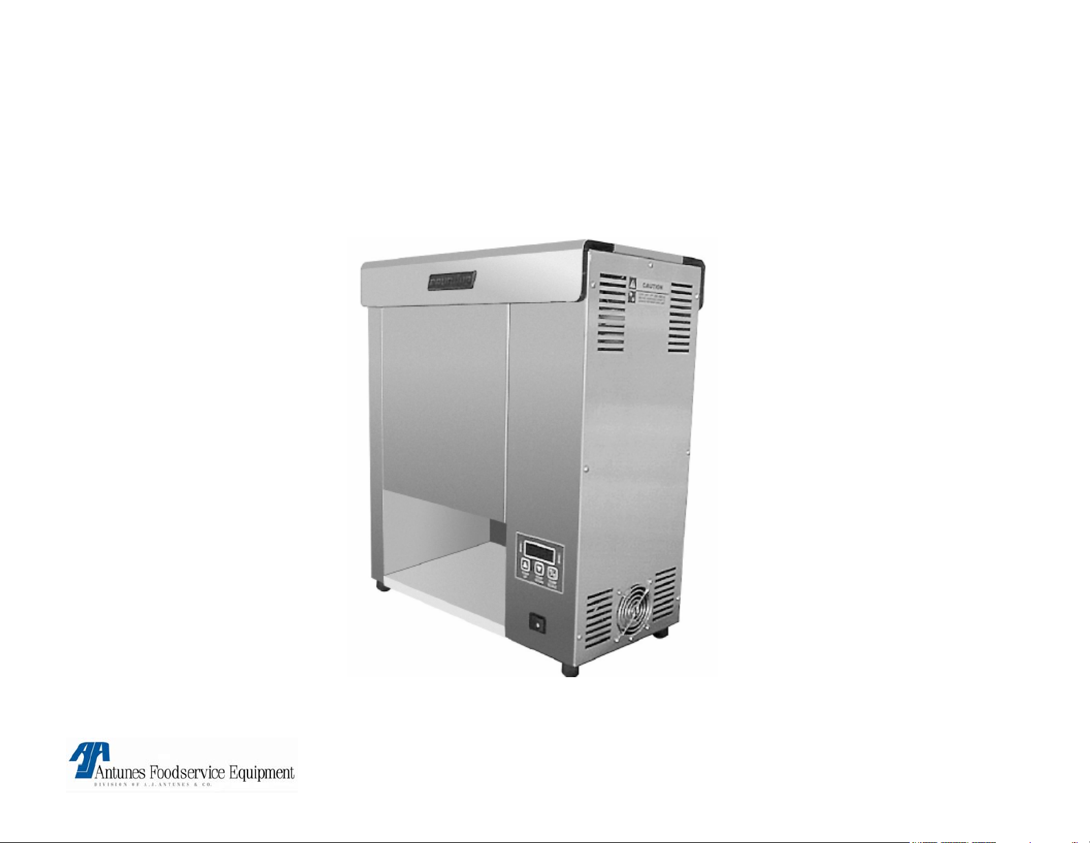
VCT-20
VCT-20 TECHNICAL MANUAL
LAST UPDATED 3-12-06
1060008 3/06 2

VCT-20
SECTION PAGE #
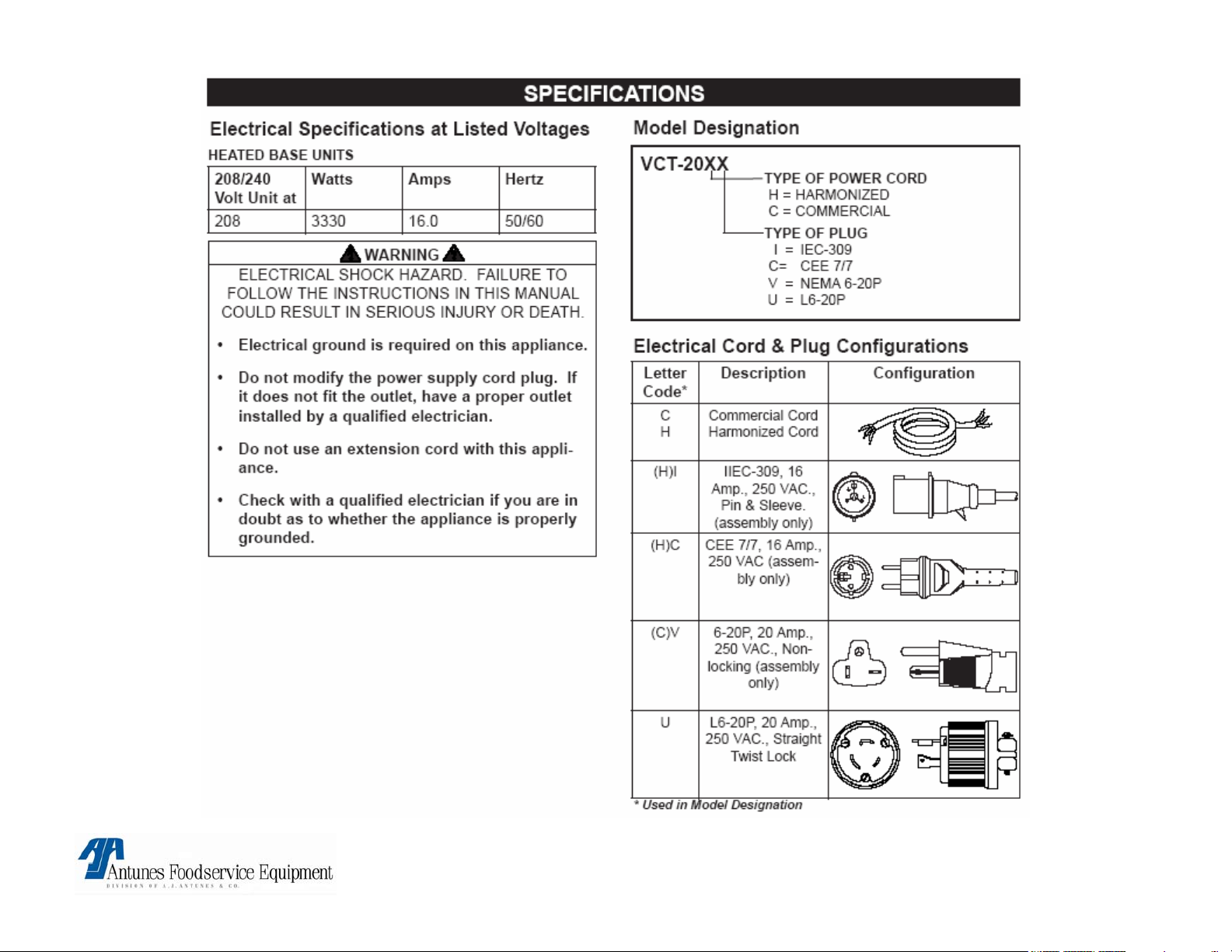
•Specifications 4
•Warnings 6
•Technical theory of operation
7
•Component description & functions 8
•Milli-volt chart 15
•Display Troubleshooting 16
•Troubleshooting 27
•Tools required 34
•Wiring diagram 35
•Parts testing & replacement 37
VCT-20 TECHNICAL MANUAL
LAST UPDATED 3-12-06
1060008 3/06 3
VCT-20 TECHNICAL MANUAL
LAST UPDATED 3-12-06
1060008 3/06 4
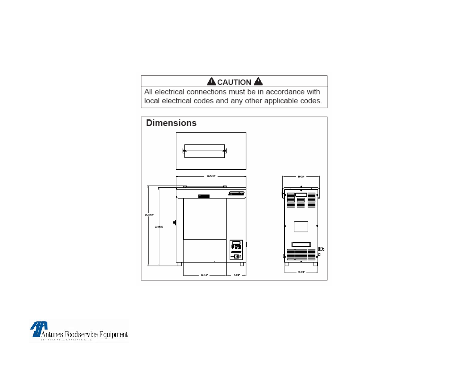
Specifications Continued
VCT-20 TECHNICAL MANUAL
LAST UPDATED 3-12-06
1060008 3/06 5
WARNING
If the supply cord is damaged, it must be replaced by the
manufacturer or its service agent or a similarly qualified
person in order to avoid a hazard.
Do not use an extension cord with this
appliance.
WARNING
WARNINGWARNING
Do not modify the power supply cord plug if it does not fit
the outlet, have a proper outlet installed by a qualified
electrician.
Check with a qualified electrician if you are in
doubt whether the appliance is properly grounded
or Not.
WARNING
Do not clean this appliance with a water jet.
! ATTENTION ! ▲ WARNING ▲ ! ATTENTION !
To avoid possible injury and/or damage to the unit, inspection, test and repair of electrical equipment should be
performed by QUALIFIED SERVICE PERSONNEL. The unit should be unplugged when servicing, except when
electrical tests are required. Use extreme care during electrical circuit tests. Live circuits will be exposed.
VCT-20 TECHNICAL MANUAL
LAST UPDATED 3-12-06
1060008 3/06 6

VCT-20 TECHNICAL THEORY OF OPERATION
Electrical/Temperature Theory
When the power switch is turned on, line voltage flows to the top cooling fan & the primary side of the step down
transformer. The transformer’s secondary side supplies 12 VAC to the control board. Once powered, & provided that
the platen temperature (Platen Heating Circuit), or the auxiliary air temperature (Auxiliary Air Heating Circuit) are
below their setpoints, the control board calls for heat by supplying 15-20 VDC to terminals 3 (+) & 4 (-) on the platen
relay or the auxiliary relay (Depending which heating circuit is calling for heat). Once powered, the relay closes
terminals 1 & 2, which allows line voltage to flow to the platen, or the auxiliary heaters. As the platen or auxiliary
heaters heat up, a type “K” thermocouple monitors the internal platen temperature, while another type “K” (Located
within the front belt wrap) monitors the auxiliary air temperature. As the heat continues to increase, so does the
thermocouple’s DC millivolts. Once the temperature approaches the setpoint, the thermocouples are relaying certain
DC millivolts to the control board (See Chart). The control board receives these millivolts & proceeds to remove the
15-20 VDC from the respective solid state relay, since the heating circuit has now become satisfied. Then, relay
terminals 1 & 2 open up, and the heater(s) stops heating. NOTE: It is normal for the VDC, VAC, & Amperage to
pulse/fluctuate when the temperature is at, or near the setpoint. NOTE: The respective heating circuit will cycle on &
off as needed, even at idle. This control board can display several fault codes (See manual for further information). If
the platen heater circuit fails & the platen overheats, a manual resettable hi-limit thermostat will trip & open the unit’s
circuits, with the exception of the axial cooling fan at the top. NOTE: If this condition should repeat, the root cause
must be determined & corrected.
Electrical/Mechanical Theory
With the unit powered, & with all its covers properly in place, the top safety interlock switch ) is activated &
completes the line voltage to the drive motor & auxiliary heaters. The drive motor runs & operates the conveyor
system. NOTE: The Auxiliary heaters will heat only if the auxiliary circuit is calling for heat, & the interlock switche is
activated. With the unit rotating & up to temperature, the bun compression knobs (Located on the side Panel) can be
set to closely match the thickness of the crown or heel. When each knob is adjusted, it rotates a horizontal cam,
which in turn, pushes two vertical compression plates towards, or away from the platen. NOTE: The platen is
covered by a teflon release sheet. Each front & rear rotating conveyor chain is wrapped with a silicone belt that helps
transfer heat to the skin side of the buns. NOTE: The belt wraps are heated by the auxiliary heaters. It also pulls the
buns down into the unit. When the buns are fed from the top & begin to go through, their cut sides become
compressed against the teflon release sheet & platen & begin to toast. The buns will drop out the bottom & onto a
heated base. (Some Models) or bun chute (Some Models).
VCT-20 TECHNICAL MANUAL
LAST UPDATED 3-12-06
1060008 3/06 7

VCT-20 Component Description & Function
Power Switch: Double Pole Single Throw, turns the supply voltage On or Off to the unit’s internal line
voltage components. NOTE: The built in led illuminates when line voltage is present into & out of the switch. If
not lit, line voltage is not present into or out of the switch.
Safety Interlock Switch A Single Pole Single Throw momentary safety switch located at the top of the
toaster. When depressed (activated) by the removable top heat shield, it completes the line voltage circuit to the
drive motor & both auxiliary heaters. If the heat shield is missing or not installed properly, the drive motor &
both auxiliary heaters will not operate.
Stepdown Transformer: Consisting of 1 primary coil & 1 secondary coil, it steps down the incoming
supply voltage to approximately 12 VAC. The 12 VAC operates the control board.
Control Board: Operates & controls the temperature display, fault codes, platen & auxiliary heating
circuits. This control board displays several fault code messages. See “Fault Codes” in Operation Section.
Platen SS Relay: Solid State, Single Pole Single Throw relay that is located within the electrical
compartment. When its input coil, (Terminals 3 + & 4 - ) is supplied VDC by the control board, it allows the line
voltage contacts (Terminals 1 & 2) to close. Once they close, line voltage is supplied to the main platen heater.
NOTE: SS relays should not be tested/diagnosed with an ohmmeter since this test is not reliable.
Testing/Diagnosing an SS relay should be conducted with the toaster & relay powered, and the use of a
voltmeter. If faulty, this relay will permanently fail open (No heat condition) or closed (Overheating condition).
They do not fail intermittently. NOTE: Terminals 3 (+) & 4 (-) are polarity sensitive. The wiring can be
inadvertently switched at the control board or at the relay if either component is ever replaced. If so, VDC will
still be present at the relay, but it will not energize. Therefore, the platen will not heat up. Always verify per
wiring diagram.
VCT-20 TECHNICAL MANUAL
LAST UPDATED 3-12-06
1060008 3/06 8

VCT-20 Component Description & Function
Auxiliary SS Relay: Solid State, Single Pole Single Throw relay that is located within the electrical
compartment. When its input coil, (Terminals 3 + & 4 - ) is supplied VDC by the control board, it allows the
line voltage contacts (Terminals 1 & 2) to close. Once they close, line voltage is supplied to the 2 auxiliary
air heaters. NOTE: SS relays should not be tested/diagnosed with an ohmmeter since this test is not
reliable. Testing/Diagnosing an SS relay should be conducted with the toaster & relay powered, and the use
of a voltmeter. If faulty, this relay will permanently fail open (No heat condition) or closed (Overheating
condition). They do not fail intermittently. NOTE: Terminals 3 (+) & 4 (-) are polarity sensitive. The wiring
can be inadvertently switched at the control board or at the relay if either component is ever replaced. If so,
VDC will still be present at the relay, but it will not energize. Therefore, the auxiliary heaters will not heat up.
Always verify per wiring diagram.
Platen: Also known as a heating plate, it is a vertically mounted aluminum casting that consists of 1
permanently integrated heating element. When powered, it generates the heat to toast, as well as to transfer
the heat internally to the cut side of the buns. It normally operates at a temperature range of approximately
550-600 F (287-315 C). NOTE: The platen must contain a teflon release sheet over it. Failure to install a
teflon release sheet on the platen will cause the buns to stick & possibly damage the platen’s aluminum
surface.
Auxiliary Heaters: Also known as calrod heaters, there are two used. One is located within the front
belt wrap & conveyor chain area & the other is located within the rear belt wrap & conveyor chain area.
Their purpose is to heat the air within the belt wrap & conveyor chain area, which in turn, heats the belt
wrap to approximately 340-400 F (171-204 C). The hot belt wraps then transfer heat through the skin side of
the buns as they are being pulled down into the unit. This increases the buns internal temperature.
VCT-20 TECHNICAL MANUAL
LAST UPDATED 3-12-06
1060008 3/06 9

VCT-20 Component Description & Function
Platen Thermocouple: A type “K” consisting of 2 wires, Red (-) & Yellow (+). One end plugs onto
the control board terminal J1, & the other end is inserted into a hole in the platen. As it monitors the
internal platen temperature, it generates & relays DC millivolts to the control board (See Millivolt Chart).
NOTE: At the control board, the thermocouple connector plugs into 3 male pins. The center pin is positive
(+) & MUST always align with the yellow wire. The two outer pins are negative (-) & either one must align
with the red wire.
Auxiliary Thermocouple: A type “K” consisting of 2 wires, Red (-) & Yellow (+). One end plugs onto
the control board terminal J2, & the other end is inserted through the stainless steel wall & secured to a
bracket located within the belt wrap & conveyor chain area. As it monitors the air temperature, it generates
& relays DC millivolts to the control board (See Millivolt Chart). NOTE: At the control board, the
thermocouple connector plugs into 3 male pins. The center pin is positive (+) & MUST always align with
the yellow wire. The two outer pins are negative (-) & either one must align with the red wire.
Hi-Limit: A capillary tube style, normally closed temperature switch that monitors the internal platen
temperature. If the heating circuit fails & runs away, the hi-limit will trip between 680-720 F (360-382 C) &
open the units line voltage circuit components, with the exception of the top axial cooling fan. NOTE: If
the hi-limit trips, the reset button must be manually pressed to reset it. If at any time a hi-limit trips, the
root cause must be determined & corrected.
Drive Motor (Conveyor Motor): An electric motor integrated with a gear box. Provides the power
& continuous rotation of the main drive chain & sprockets within the electrical compartment. The spare
red wire is only to be used in areas (Countries) with 50 hertz only.
Axial Cooling Fan: An electrical cooling fan located at the top within the electrical compartment. Its
main purpose is to provide airflow, which in turn, maintains a cooler electrical compartment.
VCT-20 TECHNICAL MANUAL
LAST UPDATED 3-12-06
1060008 3/06 10

VCT-20 Component Description & Function
Idler Shafts: Two dummy shafts located at the top front & top rear of the unit. The shafts accommodate two
conveyor sprockets. They are driven by the lower drive shafts in conjunction with the conveyor belt chains &
sprockets. NOTE: The idler shafts ends rotate within four Teflon bushings.
Drive Shafts: Two shafts located at the bottom front & rear of the unit. They are driven by the drive chain,
drive motor, & several sprockets. The shafts accommodate two conveyor sprockets, one spacer, & one drive
sprocket. NOTE: The drive shaft ends (Towards the motor side) rotates within two steel ball bearings, while the
opposite end rotates within two Teflon bushings.
Drive Chain: Resembling a bicycle chain, it transfers the torque from the drive motor assembly to the two
lower drive shafts & sprockets.
Drive Sprockets: Located at 3 & 9 o’clock, they consist of a ½” bore & attach to the end of the two lower
drive shafts. Both drive sprockets are driven by the drive chain & drive motor assembly.
Idler Sprocket Assembly: A small ½” bore idler sprocket that is attached to a bronze sleeve bushing.
Located at 10 o’clock, it allows for the drive chain to make an “S” turn between the idler sprocket & the 9 o’clock
drive sprocket. This allows the front conveyor chain to rotate & draw the buns into the toaster.
Motor Sprocket: A small 3/16” bore sprocket that attaches to the output shaft of the drive motor. It is the
main sprocket that provides the initial rotation.
VCT-20 TECHNICAL MANUAL
LAST UPDATED 3-12-06
1060008 3/06 11

VCT-20 Component Description & Function
Teflon Bushings: There are six bushings used per toaster. They are located at both ends of each of the two
top idler shafts & only on one end (Non Motor Side Only) of each of the two bottom drive shafts. They support the
shafts & allow for smooth rotation.
Steel Ball Bearings: There are two steel ball bearings used per toaster. They are located at the end (Motor
Side Only) of the two bottom drive shafts. Ball bearings are used to support the added drive assembly weight &
allow for smooth rotation.
Conveyor Chain Sprockets: There are eight conveyor chain sprockets used per toaster. Two sprockets
are attached to each of the four shafts. These sprockets rotate the conveyor belt chains.
Conveyor Belt Chains: There are two conveyor belts chains used per toaster (Front & Rear). Each belt
chain has a silicone belt wrapped around it. The chain consists of a few ½” & many ¾” pitch links. As the belt
chains & belt wraps rotate simultaneously, they draw the buns into the toaster. NOTE: The chains will stretch over
time with normal wear & will require adjustment. See Parts Testing & Replacement Procedures.
Aluminum Spacers: There are two spacers used per toaster. The spacer is located on each drive shaft
between the large conveyor chain sprocket (Closest to the motor side) & the electrical housing wall. Their
purpose is to limit the horizontal play of the drive shafts to 1/8” (3 mm). NOTE: With normal operation, the
spacers will wear & require replacement.
Tensioner Plate Assemblies: Resembling ski plates, there are four per toaster. They are positioned in
pairs within the front & rear conveyor belt chains. Each tensioner contains a white vertical teflon slide rail over its
face (The slide rails prevent metal to metal contact between tensioners & conveyor belt chains). The tensioners
purpose is to push out the conveyor belt chains, which in turn, compresses the buns up against the platen’s
teflon release sheet for toasting. NOTE: The tensioners protract & retract with the assistance of a conveyor cam.
See conveyor cam.
VCT-20 TECHNICAL MANUAL
LAST UPDATED 3-12-06
1060008 3/06 12

VCT-20 Component Description & Function
Conveyor Cams: There are two cams per toaster. Each cam is positioned horizontally & located behind
each pair of tensioner plate assemblies. One end of the cam is attached to a compression knob. When each
compression knob is set to a setting that closely matches the thickness of a bun’s crown & heel, the cam pushes
out the tensioner plates & conveyor belt chains, which in turn, compresses the buns up against the platen’s
teflon release sheet for toasting. NOTE: If the compression knob is set to 1, the cam is protracted to its
maximum. If the dial is set to 6, the cam is fully retracted.
Compression Knobs: There are two compression knobs per toaster. Each knob is located at the end of
each conveyor cam. The knobs are to be set to a setting that closely matches the thickness of a bun’s crown &
heel. The measurements listed on the label correspond to the distance (gap) between the conveyor belt chains &
platen. The buns become compressed up against the platen’s teflon release sheet for toasting. NOTE: If the knob
dial is set to 1, the cam is protracted to its maximum. If the dial is set to 6, the cam is fully retracted.
Teflon Slide Rails: There are eight teflon slide rails used per toaster. Four of them are approximately 12”
(305 mm) long & located on the face of each tensioner plate assembly. The other four are approximately 3” (76
mm) long & each is attached to a steel spring tensioner. They are located within the lower part of each conveyor
belt chain area. The slide rails prevent metal to metal contact between tensioners & conveyor belt chains &
assist in guiding the conveyor belt chains.
Roller Tensioners: There are two roller tensioners used per toaster & each is attached to the inner side of
the conveyor cover. They consist of a steel spring with roller wheel. Their purpose is to apply inward pressure to
the conveyor belt wraps & chains. This takes up the chain’s extra slack & maintains it at a constant tension.
NOTE: The roller tensioners must maintain a specific gap measurement. See Parts Testing & Replacement
Procedures.
Release Sheets: There is one teflon sheet used per toaster that consists of teflon material. It is placed over
the platen & provides a smooth surface for the buns to slide on to be toasted. NOTE: Release sheets are
consumable items that require periodic replacement. See Parts Testing & Replacement Procedures.
VCT-20 TECHNICAL MANUAL
LAST UPDATED 3-12-06
1060008 3/06 13

VCT-20 Component Description & Function
Silicone Belt Wraps: There are two silicone belt wraps (Black in color) used per toaster (Wrapped around
each conveyor belt chain). Their tacky surface assists in pulling the buns into the toaster as well as transferring
heat to the skin side of the buns. NOTE: The silicone belts wraps absorb heat generated by the auxiliary air
heaters. Silicone Belt Wraps are consumable items that require periodic replacement. See Parts Testing &
Replacement Procedures.
Heated Base: It is a 35 watt aluminum foil heater that is adhered to the underside of the steel base. Its
purpose is to heat the steel base so that the buns can be maintained warm. NOTE: This heater is not
thermostatically controlled & is on continuously as long as the power switch is on.
Top Heat Shield: When properly installed, it will shield excessive heat & depress (activate) the momentary
safety interlock switch. NOTE: If the shield is missing or installed improperly, the safety interlock switch does
not become depressed (activated), therefore the conveyors, drive motor, & auxiliary heating elements will not
operate.
Conveyor Cover Assemblies: There are two covers used per toaster. Each of which has a roller
tensioner attached to the inner side. The covers purpose is to shield the rotating conveyor belt wraps & chains.
The roller tensioners purpose is to apply inward pressure to the conveyor belt wraps & chains. This takes up the
chain’s extra slack & maintains it at a constant tension.
VCT-20 TECHNICAL MANUAL
LAST UPDATED 3-12-06
1060008 3/06 14
THERMOELECTRIC VOLTAGE IN MILLIVOLTS
TYPE “K” THERMOCOUPLE READINGS + OR – 1 MILLIVOLT
° F ° C MV ° F ° C MV ° F ° C MV
300 148.8 6.1
310 154.4 6.3
320 160.0 6.5
330 165.5 6.7
340 171.1 6.9
350 176.6 7.2
360 182.2 7.4
370 187.7 7.6
380 193.3 7.8
390 198.8 8.0
400 204.4 8.3
410 210.0 8.5
420 215.5 8.7
430 221.1 8.9
440 226.6 9.2
450 232.2 9.4
460 237.7 9.6
470 243.3 9.8
480 248.8 40.1
490 254.4 10.3
500 260.0 10.5
510 265.5 10.7
520 271.1 11.0
530 276.6 11.2
540 282.2 11.4
550 287.7 11.7
560 293.3 11.9
570 298.8 12.1
580 304.4 12.3
590 310.0 12.6
600 315.5 12.8
VCT-20 TECHNICAL MANUAL
LAST UPDATED 3-12-06
1060008 3/06 15

TEMPERATURE SET POINT ADJUSTMENT
• Platen - press and hold
temp
up and temp down.
• Auxiliary - press and hold
temp up
and temp scale.
• Must hold for over 1 sec.
• Use up & down arrows to
make adjustments to
temperature.
• Changes must occur
within 5 seconds.
570° F
NOTE: TEMPERATURE ADJUSTMENTS MUST BE DONE IN 5 DEGREE INCREMENTS UNTIL THE DESIRED
CARMELIZATION (COLOR) IS ACHIEVED.
VCT-20 TECHNICAL MANUAL
LAST UPDATED 3-12-06
1060008 3/06 16
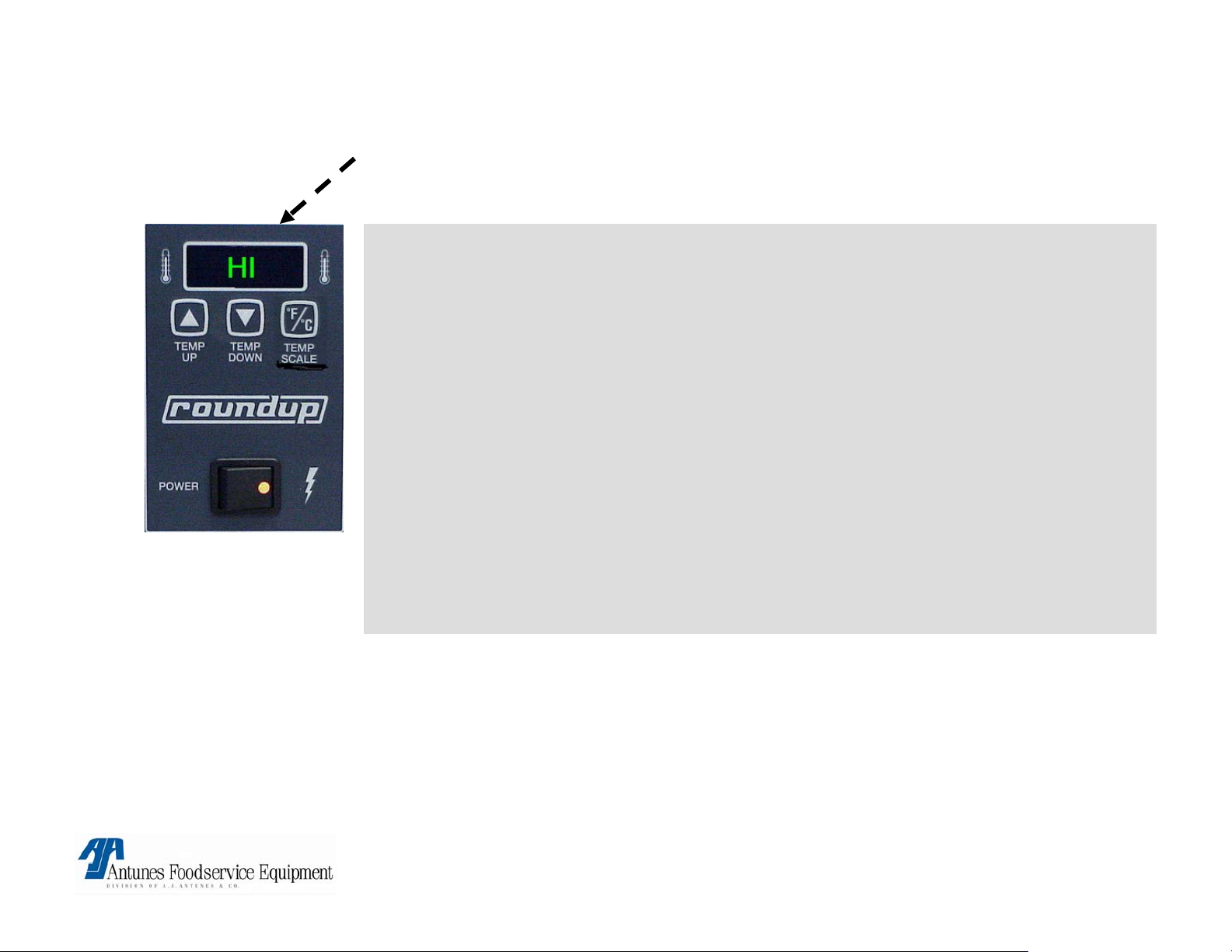
FLASHES HI “BUNS NOT TOASTING”
Possible Cause:
Loose (Platen) thermocouple
connection on Control board (J1A) or open Platen thermocouple
• Remove and reconnect connector. If still a problem, Check thermocouple
for continuity (2 to 3 OHM’S @ room temp) Between Yellow & Red wires &
replace if “open” or very high resistance.
If thermocouple checks o.k. Then faulty control board
• Circuit is miswired.
Verify per diagram.
Corrective action:
• Replace faulty component.
WARRANTY:
YES! IF IN WARRANTY PERIOD
VCT-20 TECHNICAL MANUAL
LAST UPDATED 3-12-06
.
1060008 3/06 17
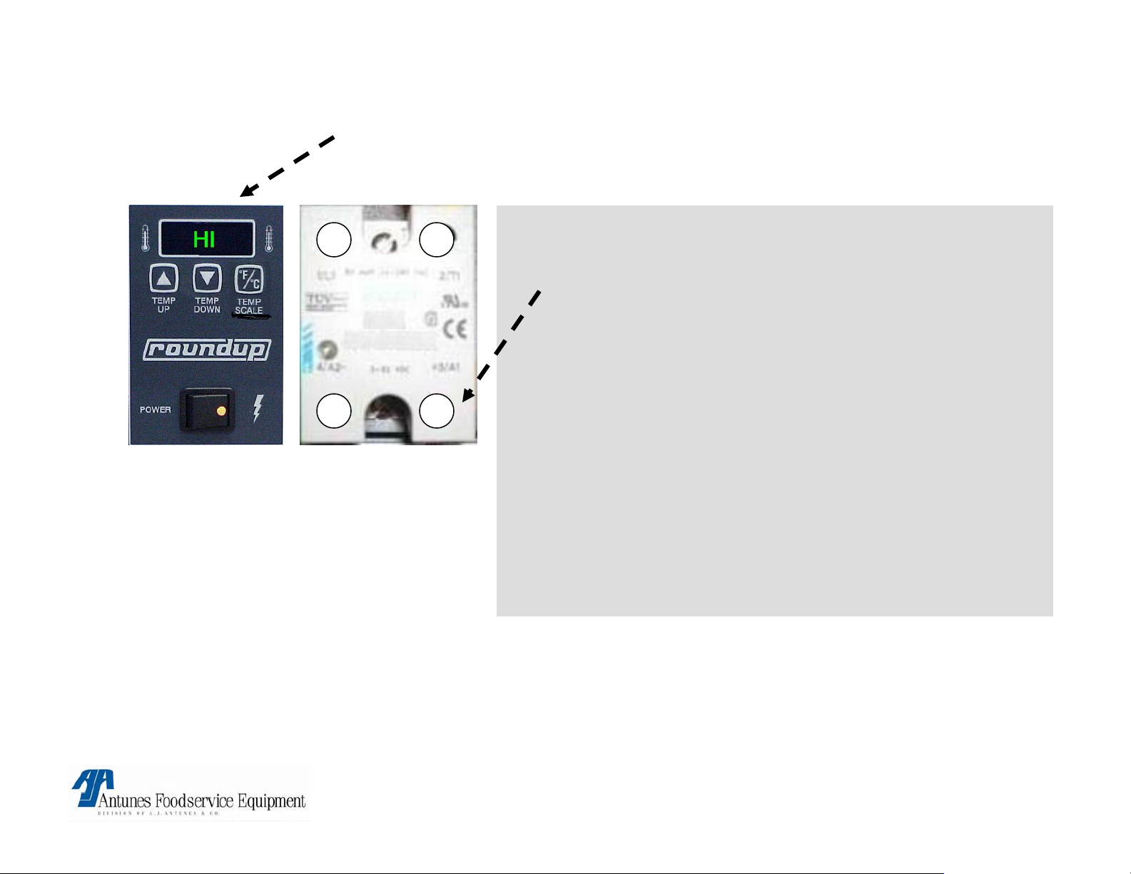
FLASHES HI “BUNS BURN”
Possible Cause:
1 2
4- 3+
NOTE: Old relays are
Black in color
• Relay:
Platen SS relay contacts 1&2 failed in closed position.
Remove red wire on relay terminal 3(+).
Is line voltage present across platen terminals ?
If yes, relay is faulty.
• Control Board:
Is 1 – 20vdc present on platen relay
terminals 3(+) & 4(-) ?
If yes, control board is faulty.
• Circuit is miswired:
verify per diagram.
Corrective action:
• Replace faulty component.
WARRANTY:
YES! IF IN WARRANTY PERIOD
VCT-20 TECHNICAL MANUAL
LAST UPDATED 3-12-06
1060008 3/06 18
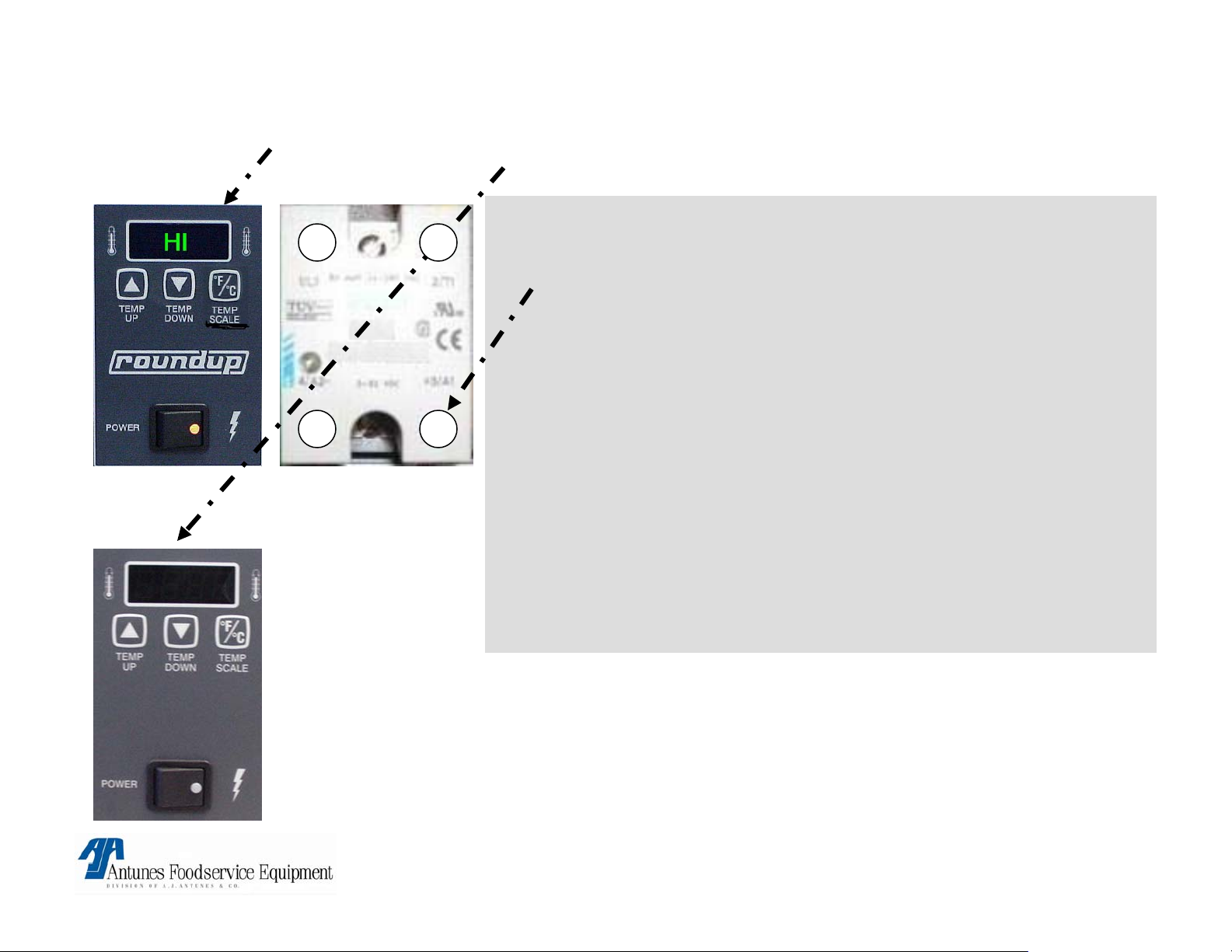
FLASHES HI “DISPLAY GOES BLANK”
Possible Cause:
1 2
3+4-
• Relay:
Platen SS relay contacts 1&2 failed in closed position.
Remove red wire on relay terminal 3(+).
Is line voltage present across platen terminals ?
If yes, relay is faulty.
• Control Board:
Is 1 – 20vdc present on platen relay terminals 3(+) & 4(-) ?
If yes, control board is faulty.
NOTE: Old relays are
Black in color
• Circuit is miswired:
verify per diagram.
Corrective action:
• Replace faulty component.
WARRANTY:
YES! IF IN WARRANTY PERIOD
VCT-20 TECHNICAL MANUAL
LAST UPDATED 3-12-06
1060008 3/06 19
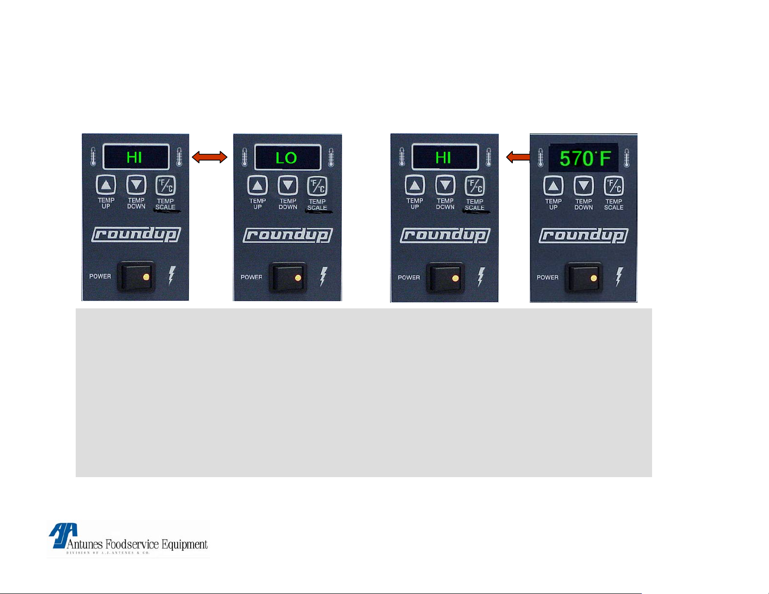
CONTROL FLASHES HI & LO @ COLD START UP &
AFTER 20\30 MIN FLASHES HI & 570° F
Possible cause:
Loose auxiliary thermocouple connection on control board. terminal (J2A).
• Remove and reconnect connector. If problem persists, check thermocouple for continuity
(2 – 3 Ohm’s @ room temp) Between Yellow & Red wires & replace if “open” or very high
resistance.
If thermocouple checks ok. Then faulty control board.
• Circuit is miswired: verify per diagram
Corrective action:
• Replace faulty component.
WARRANTY:
YES! IF IN WARRANTY PERIOD
VCT-20 TECHNICAL MANUAL
LAST UPDATED 3-12-06
1060008 3/06 20
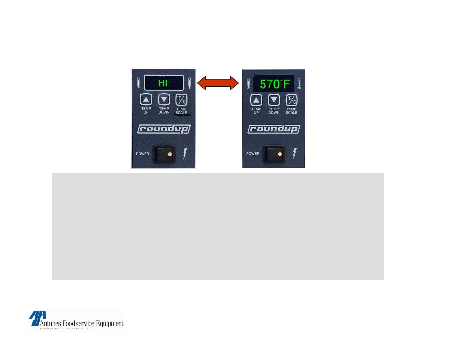
FLASHES “HI & 570° F AFTER 20 TO 30 MIN
(NEVER FLASHED HI&LO @ COLD START UP).
Possible cause:
Auxillary SS relay contacts 1&2 failed in closed position:
• Remove red wire on terminal 3(+), Is line voltage present across auxillary heater terminals
while drive motor is running ?
If yes relay is faulty.
• Circuit is miswired: verify per diagram.
• Control board:
If relay checks o.k. Control board is faulty.
Corrective action:
• Replace failed components.
WARRANTY:
YES! IF IN WARRANTY PERIOD
VCT-20 TECHNICAL MANUAL
LAST UPDATED 3-12-06
1060008 3/06 21
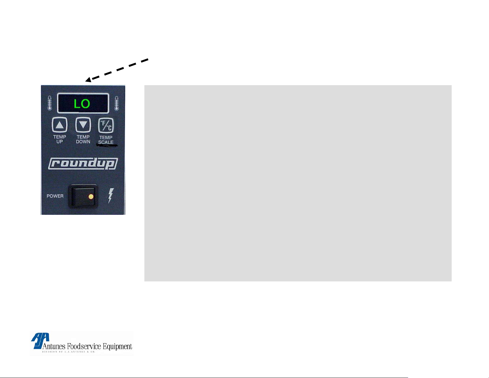
FLASHES LO “BUNS NOT TOASTING”
Possible Cause:
Platen not up to temp
allow 30 min for full warm up.
Platen SS. Relay contacts 1&2 are not closing.
Verify 15 to 20 VDC on relay terminals 3+ & 4-. If present, check for line
voltage across platen terminals. If not present faulty relay.
• Loose\burnt\open wiring in platen circuit.
Verify wiring for continuity & per wiring diagram.
• Circuit miswired.
Verify per diagram.
• Control board.
If above checks are ok. Faulty control board.
Corrective action:
• Replace faulty components.
WARRANTY:
YES! IF IN WARRANTY PERIOD
VCT-20 TECHNICAL MANUAL
LAST UPDATED 3-12-06
1060008 3/06 22
 Loading...