

Antunes VCT-100 Installation Manual
VERTICAL CONTACT TOASTER
MODEL VCT-100
SERIES 9200XX
Place this chapter in the Bun Toaster section
of your Equipment Manual
MANUFACTURED
EXCLUSIVELY FOR
McDONALD’S®
BY
AJ ANTUNES & CO
1025 NATIONAL AVE
ADDISON, ILLINOIS 60101, USA
PHONE: 1 (630)543-8650
TOLL FREE: 1-800-253-2991
FAX: 1 (630) 543-0359
THIS OWNER'S MANUAL IS FOR THE FOLLOWING
MANUFACTURING NUMBERS: 9200290 & 9200292
TABLE OF CONTENTS
WARRANTY Page 1
INTRODUCTION Page 2
ORDERING AND SERVICE INFORMATION Page 3
EQUIPMENT SET-UP Page 4
OPERATION, CLOSE PROCEDURES, MONTHLY MAINTENANCE Page 6
PARTS IDENTIFICATION AND FUNCTION Page 7
EXPLODED VIEWS Page 11
TROUBLESHOOTING GUIDE Page 14
PARTS REPLACEMENT Page 20
TEMPERATURE ADJUSTMENT PLATEN Page 20
TEMPERATURE ADJUSTMENT AUX Page 22
WIRING DIAGRAM Page 24
Equipment manufactured by Roundup Food Equipment Division of A J Antunes & Co has been constructed of the finest materials available and
manufactured to high quality standards These units are warranted to be free from mechanical and electrical defects for a period of one year from
date of purchase under normal use and service, and when installed in accordance with manufacturer's recommendations To insure continued
proper operation of the units, follow the maintenance procedure outlined in the Owner's Manual
1 This warranty does not cover cost of installation, defects caused by improper storage or handling prior to placing of the Equipment This warranty
does not include overtime charges or work done by unauthorized service agencies or personnel This warranty does not cover normal mainte-
nance, calibration, or regular adjustments as specified in operating instructions, or manuals (see Owner's Manual of specific product);
and/or labor involved in moving adjacent objects to gain access to the Equipment This warranty does not cover consumable items such as grill
covers (Teflon Sheet) This warranty does not pay travel, mileage, or any other charges for a service to reach the equipment's location (unless
stated in the Owner's Manual)
2 Roundup reserves the right to make changes in design or add any improvements on any product The right is always reserved to modify equipment
because of factors beyond our control and government regulations Charges to update equipment do not constitute a warranty charge
3 If shipment is damaged in transit the purchaser should make his claim directly upon the carrier Careful inspection should be made of the shipment
as soon as it arrives and visible damage should be noted upon the carrier's receipt Damage should be reported to the carrier This damage is not
covered under this warranty
4 Warranty charges do not include freight or foreign, excise, municipal or other sales or use taxes All such freight and taxes are the responsibility of
the purchaser
5 THIS WARRANTY IS EXCLUSIVE AND IS IN LIEU OF ALL OTHER WARRANTIES, EXPRESSED OR IMPLIED, INCLUDING ANY IMPLIED
WARRANTY OR MERCHANTABILITY OR FITNESS FOR A PARTICULAR PURPOSE, EACH OF WHICH IS HEREBY EXPRESSLY
DISCLAIMED THE REMEDIES DESCRIBED ABOVE ARE EXCLUSIVE AND IN NO EVENT SHALL ROUNDUP BE LIABLE FOR SPECIAL
CONSEQUENTIAL OR INCIDENTAL DAMAGES FOR THE BREACH OR DELAY IN PERFORMANCE OF THIS WARRANTY
1010701 10/97
© 1997 McDonald's Corporation Printed in All Rights Reserved
The United States of America
This manual is for the exclusive use of licensees and employees of McDonald's Systems, Inc
INTRODUCTION
receptacle with separate electrical
tains or other combustible materials.
The Antunes Vertical Contact Toaster, Model
VCT-100 is designed for contact toasting of
buns. The toaster is designed to allow the operator to place the buns on both sides of the heated platen at the same time. Buns are placed into
the bun feeder on the top of the toaster. Uniform
golden-brown, warm buns are retrieved at the
base of the toaster.
Hazard Communication Standard (HCS) —
The procedures in this chapter include the
use of chemical products. These chemical
products will be highlighted with bold face
letters followed by the abbreviation (HCS).
See Hazard Communication Standard (HCS)
Manual for the appropriate Material Safety
Data Sheet(s) (MSDS).
WARNING
The toaster should be grounded
according to local electrical codes to
prevent the possibility of electrical
shock. It requires a grounded
lines, protected by fuses or circuit
breaker of the proper rating.
CAUTION
Bread may burn. Therefore toasters
must not be used near or below cur-
They must be watched.
ELECTRICAL RATINGS:
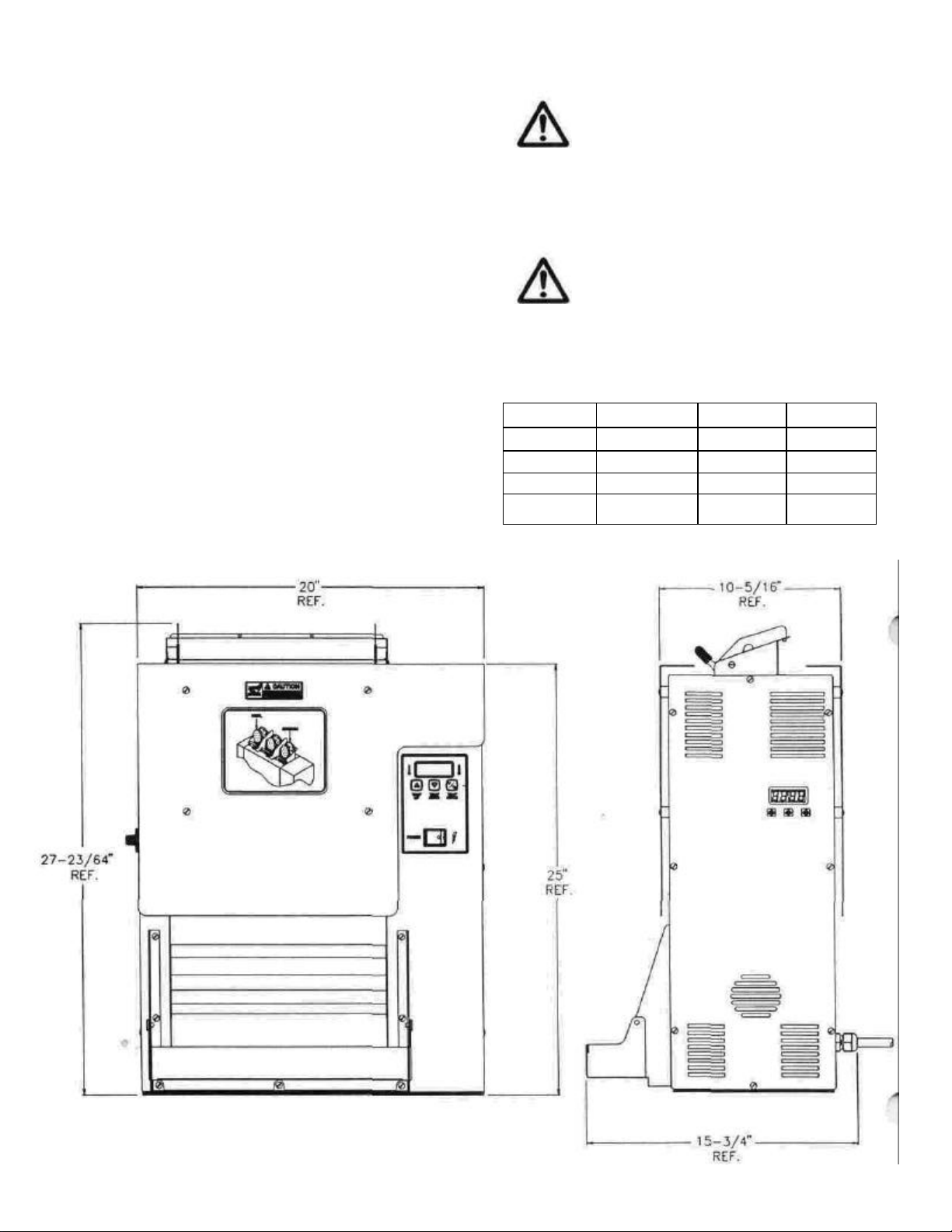
DIMENSIONS
20 inches (508 mm) wide
15 3/4 inches (400 mm) deep
27 3/8 inches (695 mm) high
VOLTAGE WATTS AMPS HERTZ
208 4200 20.2 50/60
220 4699 21.4 50/60
230 5135 22.3 50/60
240 5591 23.3 50/60

ORDERING/SERVICE INFORMATION
Use only genuine Antunes replacement parts in this unit.
Use of replacement parts other than those supplied by the
manufacturer voids the warranty and U.L. status.
Your Authorized Service Agency has a parts price list and
inform you of the cost of parts.
Parts Location - To find items you want to order from the
Parts List, proceed as follows:
1. Look at the parts drawing to locate the correct part
needed.
2. Use the item number from the parts drawing to
locate the correc t parts in the Parts List. This
section will have the Antunes part number and a
description of the part.
Ordering Information - After finding the parts you want to
order on the Parts List, write down the following
information.
Model Number: VCT-100
Manufacturer: A.J. Antunes & Co.
* Serial Number: ______________ S/N
* Manufacturing Number____________
Item Number: ___________________
Part Number: ___________________
___________________
Commonly replaced items are stocked by your
Authorized Service Agency and will be sent out
when your order is received. Other parts will be
ordered by your Authorized Service Agency from
A.J. Antunes & Co.
If technical help is needed, contact the factory
service department. Please have the following
information ready when you call our factory service department:
1. Manufacturer: A.J. Antunes & Co.
2. Model Number: VCT-100
*3. Serial Number: ____________S/N
*4. Manufacturing Number: __________
5. Nature of service problem and symptoms.
Till in for your records.
AUTHORIZED RETURN POLICY:
No product may be returned without Antunes'
prior written approval. Transportation charges
are to be prepaid by Buyer. Returned goods are
subject to Antunes' inspection and acceptance.
Antunes may, at its discretion, replace any or all
returned items within a reasonable time after
Antunes determines that the returned goods are
not in accordance herewith; and in such event
Antunes shall not be liable for any damages
arising from the defective delivery or delay
caused thereby. When expressly authorized by
Antunes in writing, unused products may be
returned to Antunes, subject to service handling,
restocking and rebuilding charges to "as new"
condition.
Follow instructions below before operating this unit.
CAUTION
You must remove the push -on fasteners
before operating this unit.
(Push-on fasteners are used for shipping
purposes only) -
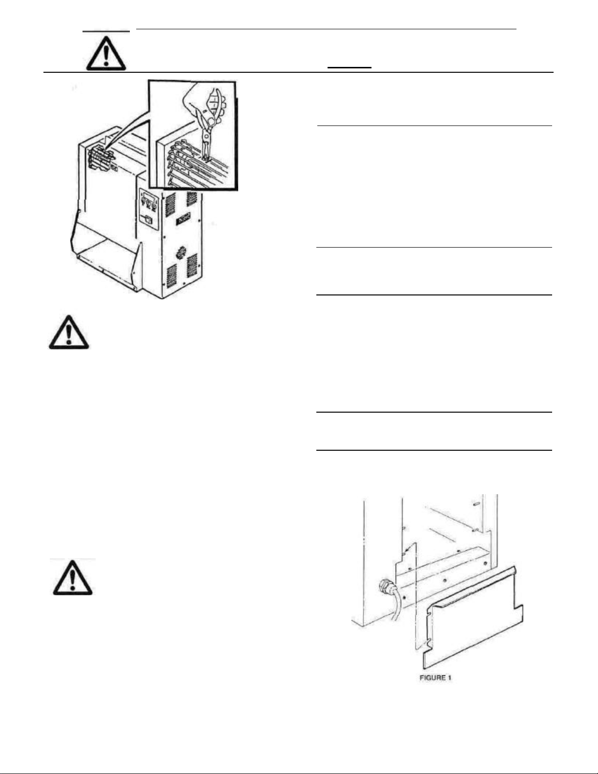
REMOVE PUSH-ON FASTENERS FROM THE
TENSIONERS ON MODEL VCT-100
• This procedure removes the Push -On
Fasteners from the Tensioners on your
VCT-100. The Push -On Fasteners are
needed for shipping only and are not
required for operation.
• This Toaster has four (4) Tensioner
Assemblies, two (2) on each side. Each
Tensioner Assembly has four (4) Push -On
Fasteners, two at the top and two at the bottom. This is a total of sixteen (16) Push -On
Fasteners. We recommend removing ALL
the Push -On Fasteners during this procedure.
WARNING
Disconnect the unit from main power
before any servicing is done.
1. Remove both Conveyor Cover Assy.(s) (Item
3).
2. Remove Conveyor Belt Wrap (Item 24). (See
Conveyor Belt Wrap on Page 21.)
3. Locate Push -On Fastener at the top of
Tensioner Assembly (See illustration
above).
4. Squeeze sides of Push -On Fastener as
shown in illustration. Pull Push -On Fastener
off the Tensioner Arm and discard.
CAUTION
NOTE: Push-On Fasteners are used to
secure Tensioner Arms during
shipping and should not be used
during operation of this unit.
5. Locate and remove the remaining Push -On
Fasteners.
6. Install Conveyor Belt Wrap.
7. Reattach the Conveyor Cover Assy.(s).
8. Test operation of Toaster before returning to
service.
INSTALLATION
1. Remove unit and all packing materials from
shipping carton.
NOTE: Save the large box marked "DO NOT
DISCARD-PARTS INSIDE". The large box
contains parts needed for opera tion of
your unit.
2. Place the unit in desired position.
3. Open the large box and check the parts inside.
Your box should contain:
• Back Door (Item 46)
• Base Extension
• Bun Feeder (Item 26)
• Bun Chute (Item 60)
• Plastic bag containing the Owners Manual and
three (3) Grill Covers.
NOTE: If any parts are missing or damaged, contact
Antunes Technical Service IMMEDIATELY at 1800-253-2991.
4. Remove all protective coverings from unit and
parts, if needed.
5. Install Back Door as shown in Figure 1.
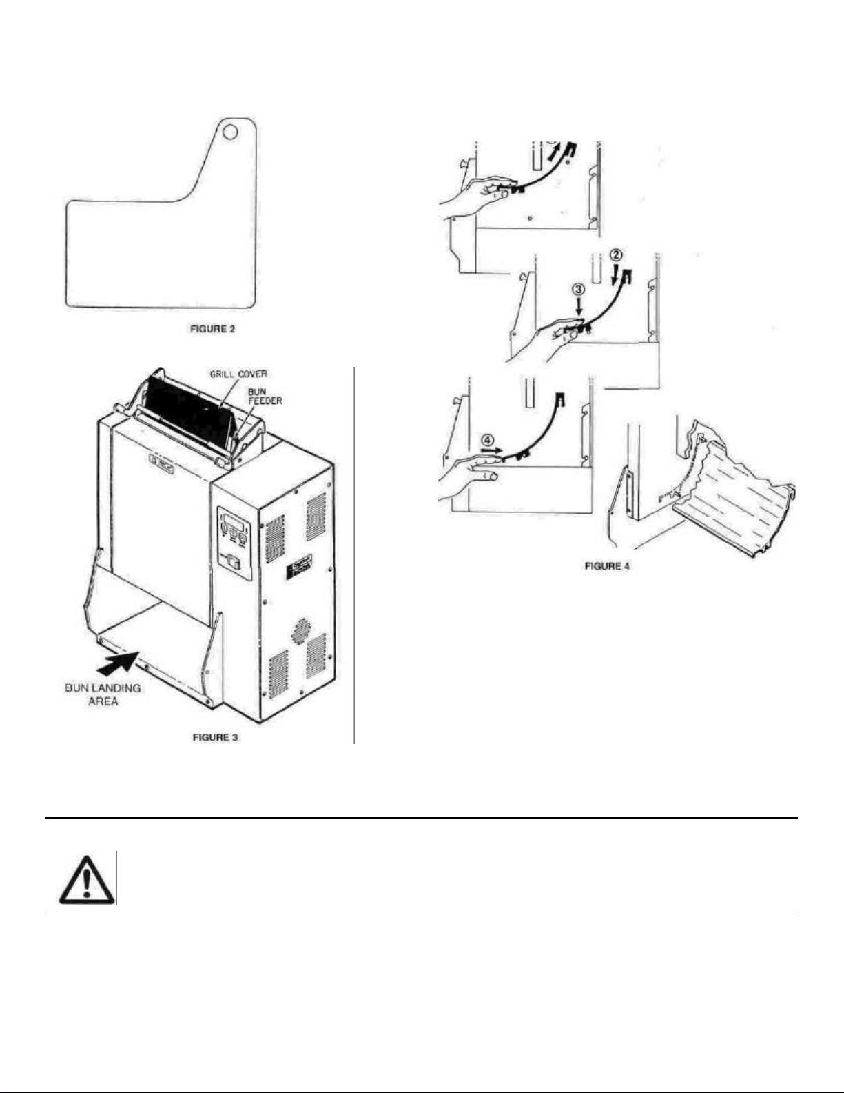
6. Install Base Extension.
7. Install Bun Feeder as shown in Figure 3.
9. Install Bun Chute as shown in Figure 4.
8. Remove a Platen Cover from the plastic bag and
install (See "Installation of Platen Cover" on Page 23).
CAUTION
Failure to use platen cover may result
NOTE: Additi onal platen covers can be ordered
in loss of warranty coverage.
through your authorized service agency. P/N
7000110(3 per pack) P/N 7000111 (10 per
pack)
10. Set Bun Adjustment Knobs (Item 30),
found on left side of unit. Start with:
Crowns (back adjustment) set at 11/16"
(#5), and Heels (front adjustment) set at
9/16"(#3).
cleaners. Do not use chemical
lt Wrap" on
6
WARNING
ELECTRICAL SHOCK HAZARD
• Electrical ground is required on this
appliance.
• Do Not modify the power supply cord plug. If
it does not fit the outlet, have a proper outlet
installed by a qualified electrician.
• Do Not have a fuse in the neutral or grounding
circuit. A fuse in the neutral or grounding circuit could result in an electrical shock.
•Do Not use an extension cord with this
appliance.
• Check with a qualified electrician if you are in
doubt as to whether the appliance is properly
grounded.
Failure to follow these instructions could result
in serious injury or death.
12. Connect unit to power supply (see Specification
Plate for proper voltage).
13. Test unit before putting into service.
NOTE: Display on front of unit will flash "LO"
until operating temperature is reached.
See "TEMPERATURE ADJUSTMENT"
on page 20 for adjustment procedure.
OPERATION
1. Connect Unit to power supply.
2. Turn bun adjustment knobs (Item 30) to
desired setting.
3. Move Rocker Switch (Item 20) to "ON" posi
tion.
4. Temperature settings of Platen must be
550°F (288°C) and Auxiliary Heaters to be
400°F (204C).
NOTE: Allow 30 minute warm-up time
before proceeding.
6. Toasted heel and crown will drop on to the
Bun Landing Area.
NOTE: Test at least three buns before
putting Toaster into service.
CLOSE PROCEDURES
When the toaster is cool, remove the Platen
(Teflon Sheet) Cover, Bun Feeder and wide
exterior of unit. Clean with Kay Chemical McD
All Purpose Solution and allow to air dry.
NOTE: Do not use abrasives on Platen
Cover.
Re-install all parts after drying.
MONTHLY MAINTENANCE
1. Move Rocker Switch (Item 20) to "OFF"
position and unplug power cord.
2. Perform Close Procedures.
3. Remove Conveyor Belt Wrap. (See
"Conveyor Belt Wrap", Page 21).
4. Clean Belts with Kay Chemical McD All
Purpose Solution and allow to air dry.
5. Clean the platen surface with a clean, damp
cloth and allow to air dry.
CAUTION
Do not use abrasive pads or
cleaners on the platen surface.
6. Reverse above procedures to assemble the
toaster.
CAUTION
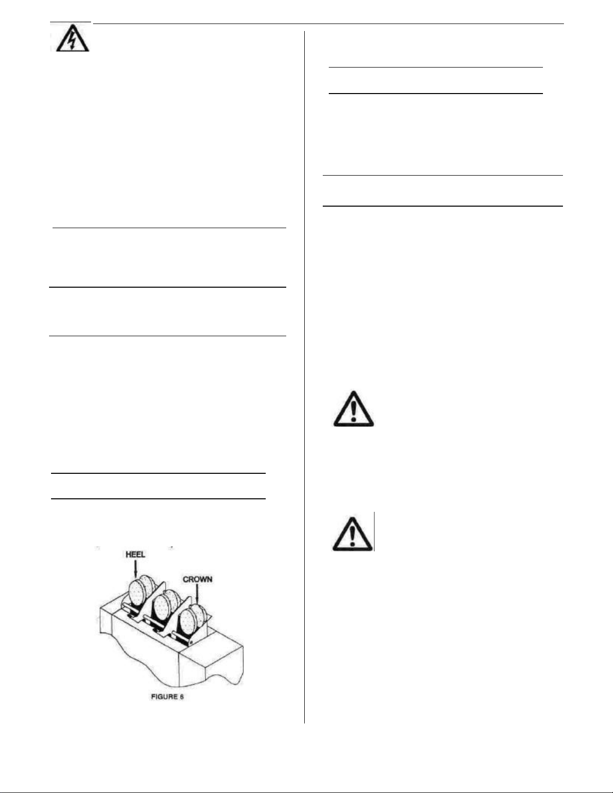
5. Drop buns into Toaster. Cut sides of heel
and crown must face each other (heel in
front crown in back as shown in Figure 6
Refer to "Conveyor Be
page 21. Incorrectly installed conveyor belt wrap may cause "jam ming" or other problems.
7. Toaster is ready for operation.

PARTS IDENTIFICATION AND FUNCTION
ITEM PART NO. DESCRIPTION QTY
FUNCTION
1 0010190 CONVEYOR BELT 2 FLEXIBLE ASSEMBLY USED TO MOVE BUNS THROUGH THE
0800204 1/2" PITCH LINK (SMALL) 3 SMALLER COMPONENT OF CONVEYOR BELT.
0800121 3/4" PITCH LINK (LARGE) 38 LARGER COMPONENT OF CONVEYOR BELT.
2 2150117 IDLER SHAFT 2 SERVES AS UPPER AXLE FOR CONVEYOR BELT.
3 0011240 CONVEYOR COVER ASSY (Front) 1 SHEET METAL PART COVERING MOVING PARTS.
0011250 CONVEYOR COVER ASSY (Back) 1
4 0011242 TENSIONER ASSY 4 GUIDES CONVEYOR BELT.
5 0800332 ROD, CONVEYOR COVER 2 BOTTOM SUPPORT FOR CONVEYOR COVER ASSY.
6 215K111 SPROCKET 8 USED TO MOVE CONVEYOR BELT.
7 212K103 SPACER KIT 1 METAL RING USED TO CORRECTLY POSITION DRIVE SHAFT.
8 0503317 CONTROL COVER 1 SH EET METAL PART COVERING ELECTRICAL PARTS.
9 2150118 DRIVE SHAFT 2 SERVES AS LOWER AXLE FOR CONVEYOR BELT.
10 0700482 POWER CORD/PLUG ASSY
PIN AND SLEEVE PLUG,
(VCT-100RD, #9200290)
0700477 POWER CORD/PLUG ASSY
TWIST-LOCK PLUGSTRAIGHT (VCT-100RS, #9200292)
TOASTER.
1 TRANSFERS ELECTRIC POWER TO THE UNIT.
1
11 4070030 CONTROL BOARD (PLATEN) 1 MAINTAINS AND CONTROLS HEAT TO PLATEN.
12 2150158 BALL BEARING 8 ALLOWS SMOOTH ROTATION OF DRIVE SHAFTS.
13 050K115 BEARING RETAINER KIT 1 POSITIONS AND HOLDS BALL BEARING.
14 2150185 DRIVE SPROCKET 1 TOOTHED METAL PART THAT TRANSFERS POWER TO DRIVE
15 2150178 DRIVE CHAIN (VCT-100) 1 USED TO TRANSFER POWER FROM MOTOR SPROCKET TO
16 0011193 IDLER SPROCKET ASSY 1 REVERSES DRIVE CHAIN MOTION.
17 0500330 MOTOR MOUNTING BRKT. 1 METAL SUPPORT USED TO SECURE MOTOR BRACKET TO
18 4000164 MOTOR 1 ELECTRICAL PART USED TO MOVE DRIVE CHAIN.
19 2150129 MOTOR SPROCKET 1 USED TO MOVE DRIVE CHAIN.
20 4010137 SWITCH, ROCKER (250 VAC) 1 CONTROLS ELECTRICAL POWER TO THE UNIT. LIGHTS UP
21 4060304 TERMINAL BLOCK 1 PROVIDES CONNECTION POINT FOR ELECTRICAL WIRES.
22 405K125 SOLID STATE RELAY 2 SWITCHES POWER ON AND OFF FOR THE PLATEN.
23 4010187 TRANSFORMER 1 PROVIDES CORRECT POWER FOR CONTROL BOARD.
24 0400304 CONVEYOR BELT WRAP 2 SILICONE COVER THAT PREVENTS DAMAGE TO BUNS AND
SHAFTS FROM DRIVE CHAIN.
DRIVE SPROCKET.
TOASTER.
WHEN POWER IS ON.
HOLDS TO HEAT THE BUNS.
25 0011191 ROLLER TENSIONER ASSY 2 METAL PART THAT KEEPS CONVEYOR BELT AT PROPER
TENSION.

ITEM PART NO. DESCRIPTION QTY FUNCTION
26 0011247 BUN FEEDER ASSEMBLY 1 SHEET METAL PART THAT HOLDS BUNS AND GUIDES THEM INTO
27 050K114 ROD BRACKET KIT 2 METAL PART THAT HOLDS TENSION ER AND ALLOWS IT TO
28 1001006 CONTROL LABEL 1 IDENTIFIES CONTROLS.
29 1001008 DIAL LABEL (PKG. OF 10) 1 IDENTIFIES BUN THICKNESS SETTINGS.
30 2100253 KNOB 2 MOVES CONVEYOR CAM TO PROVIDE THICKNESS ADJUSTMENT.
31 0503195 COVER, END HOUSING 1 SHEET METAL PART THAT COVERS MECHANICAL COMPONENTS.
32 4050209 THERMOCOUPLE ASSY. 1 SENSES TEMPERATURE.
33 215K158 BEARING RETAINER KIT 6 POSITIONS AND HOLDS BALL BEARING.
34 0021103 END HOUSING WELDMENT
35 1001003 CROWN/HEEL LABEL 1 IDENTIFIES PLACEMENT OF BUNS.
36 7000110
7000111
37 0100215 PLATEN (208 VOLT) 1 HEATED ALUMINUM CASTING.
38 0021123 CONTROL HOUSING 1 PROTECTIVE METAL SIDE, SUPPORTS INTERNAL COMPONENTS.
WELDMENT
PLATEN COVER (PKG. OF 3)
PLATEN COVER (PKG. OF 10)
THE TOASTER.
MOVE DURING ADJUSTMENT.
1 PROTECTIVE METAL SIDE, SUPPORTS INTERNAL PARTS.
COMPONENTS.
— TEFLON PART THAT COVERS PLATEN, CREATES SMOOTH
TOASTING SURFACE.
39 7000121 SLIDE RAIL KIT (INCLUDES 2 SLIDE
RAILS FOR TENSIONERS)
40 0021122 CONVEYOR CAM 2 POSITIONS CONVEYOR BELT TO TOAST DIFFERENT THICKNESS
45 7000119 THERMOCOUPLE RETAINER KIT 1 HOLDS THERMOCOUPLE IN PLACE.
46 0503200 PANEL, REAR 1 SHEET METAL PART - COVERS BACK OF BUN PAN AREA.
47 4030162 HIGH LIMIT THERMOSTAT 1 RESETTABLE SAFETY SWITCH WHICH TURNS THE POWER OFF
48 0400310 STRAIN RELIEF 1 HOLDS POWER CORD SET TO CABINET.
51 0011196 FLOOR ASSEMBLY 1 SHEET METAL PART - CREATES SPACE FOR BUN PAN.
54 4030326 HEATER 1 PART IS GLUED TO BOTTOM OF FLOOR ASSEMBLY, PROVIDES
55 0503192 BASE 1 SHEET METAL PART - COVERS BOTTOM OF UNIT.
56 0503155 MOTOR BRACKET 1 METAL SUPPORT USED TO SECURE DRIVE MOTOR TO MOTOR
0700561 WIRE SET 1 *57
0700564 WIRE SET 1
58 0200208 GASKET,BASE 1 SEALS UNIT TO COUNTER.
59 0021150 BASE EXTENSION 1 PREVENTS BUNS FROM FALLING OFF.
60 0503198 BUN CHUTE 1 GUIDES BUNS INTO BUN PAN AFTER TOASTING.
2 PREVENTS METAL-TO-METAL CONTACT AND LIMITS NOISE.
OF BUN.
TO THE STEAM GENERATOR WHEN THE THERMOSTAT IS NOT
CONTROLLING MAXIMUM TEMP.
HEAT IN BUN PAN AREA.
MOUNTING. BRACKET.
PERMITS CONNECTION OF ALL ELECTRICAL PARTS.
NOT SHOWN
 Loading...