

Page 1

180 Kehoe Blvd.
Carol Stream, Illinois 60188 USA
1-877-392-7854 (Tech Service).
TBS-1X / 2X TECHNICAL MANUAL LAST UPDATE 8-10-04
MANUFACTURING # 9100400, 02, 410, 412
1060001 8/04
Page 2
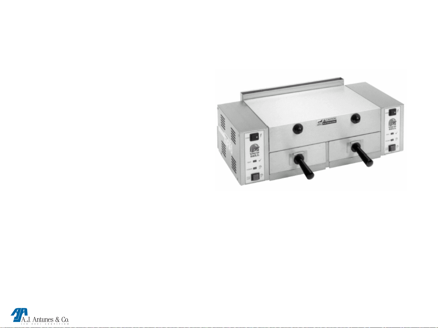
TBS-1X & 2X
STEAMER
TRAINING
TBS-1X / 2X TECHNICAL MANUAL LAST UPDATE 8-10-04
MANUFACTURING # 9100400, 02, 410, 412
1060001 8/04
Page 3
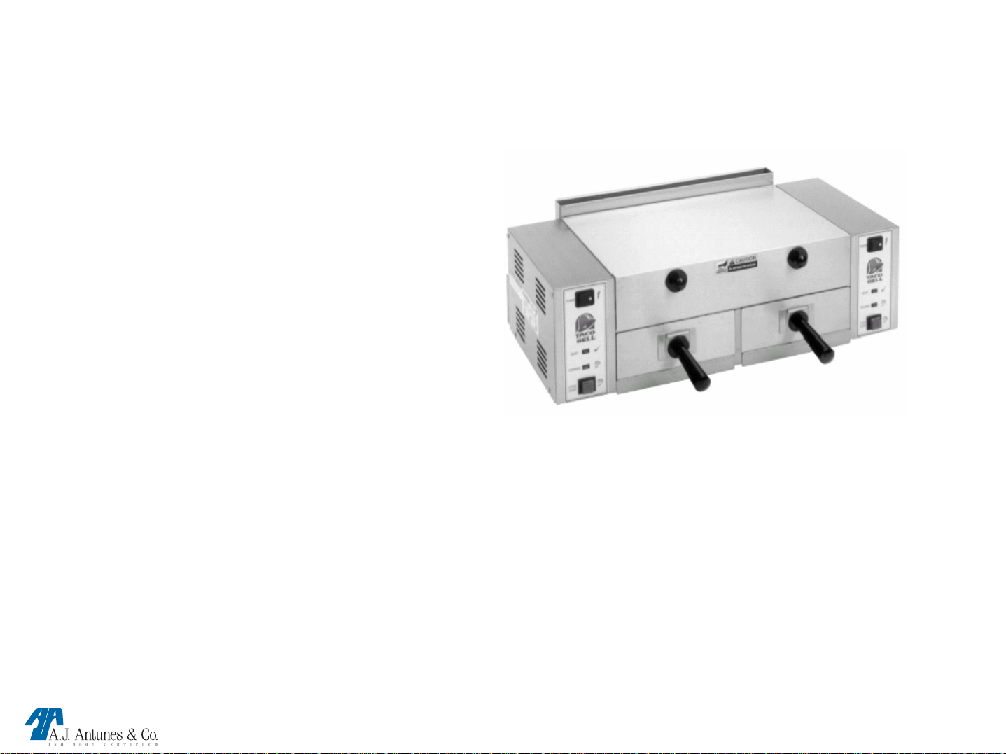
TBS-1X & 2X
MFG#9100400,9100402,9100410 & 9100412
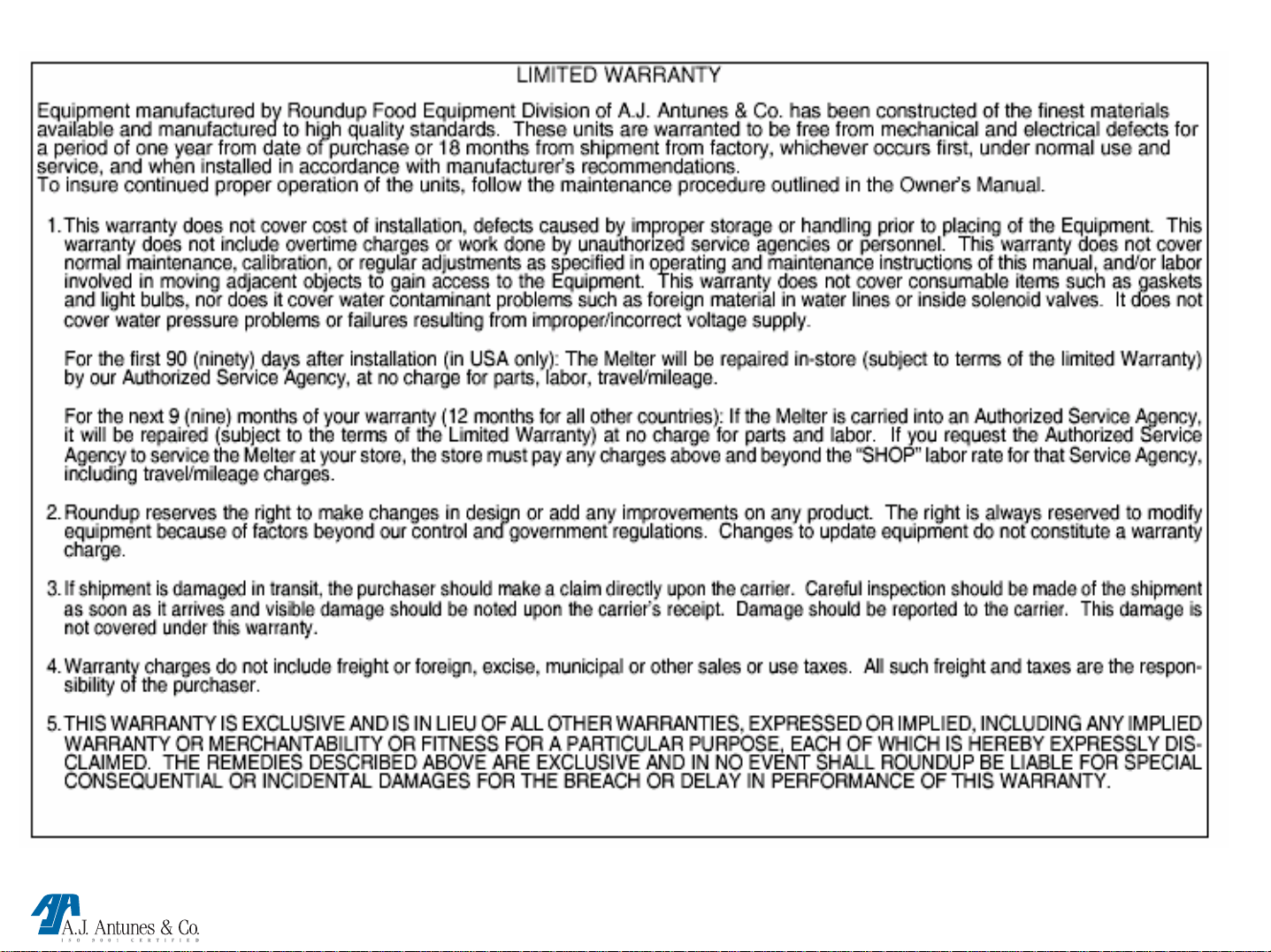
•Warranty
•Specifications
•Steamer warnings
•Steamer installation
•Operating instructions
•Technical Theory of operation
•Component description & function
•Tools required
•Steamer maintenance
•Trouble shooting
•Parts testing & replacement
•Wiring Diagram
TBS-1X / 2X TECHNICAL MANUAL LAST UPDATE 8-10-04
MANUFACTURING # 9100400, 02, 410, 412
1060001 8/04
Page 4
TBS-1X / 2X TECHNICAL MANUAL LAST UPDATE 8-10-04
MANUFACTURING # 9100400, 02, 410, 412
1060001 8/04
Page 5
TBS-1X / 2X TECHNICAL MANUAL LAST UPDATE 8-10-04
MANUFACTURING # 9100400, 02, 410, 412
1060001 8/04
Page 6
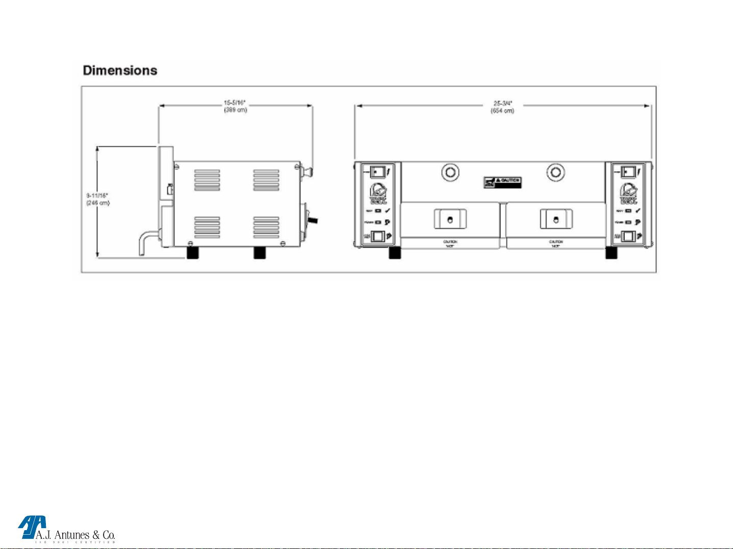
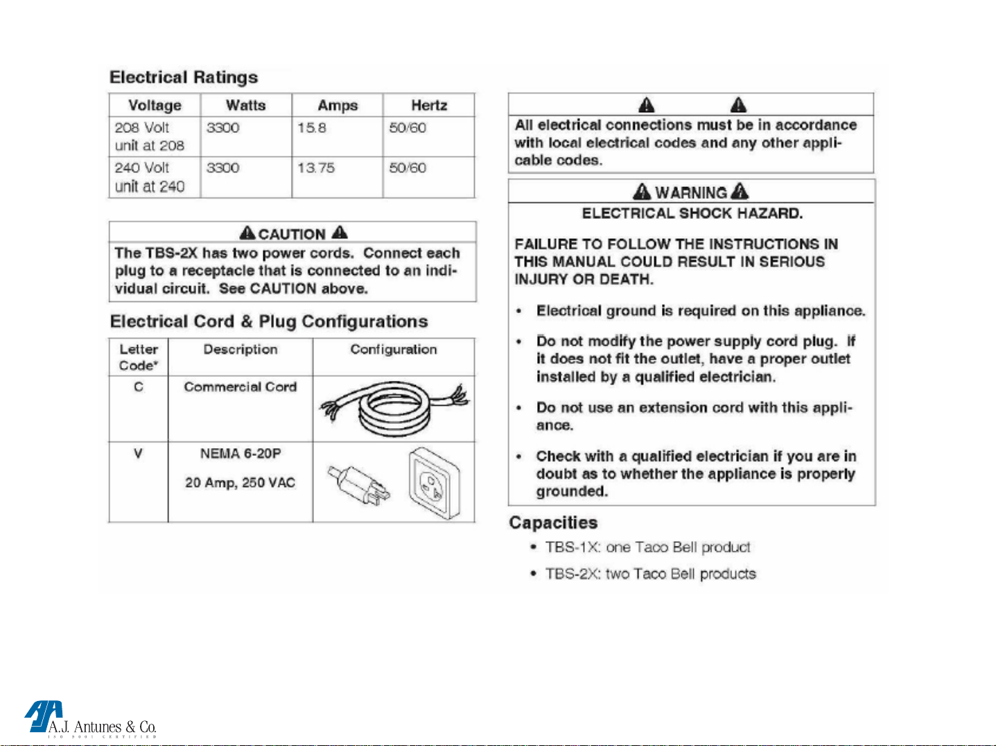
SPECIFICATIONS
TBS-1X / 2X TECHNICAL MANUAL LAST UPDATE 8-10-04
MANUFACTURING # 9100400, 02, 410, 412
1060001 8/04
Page 7
IMPORTANT SAFETY INFORMATION
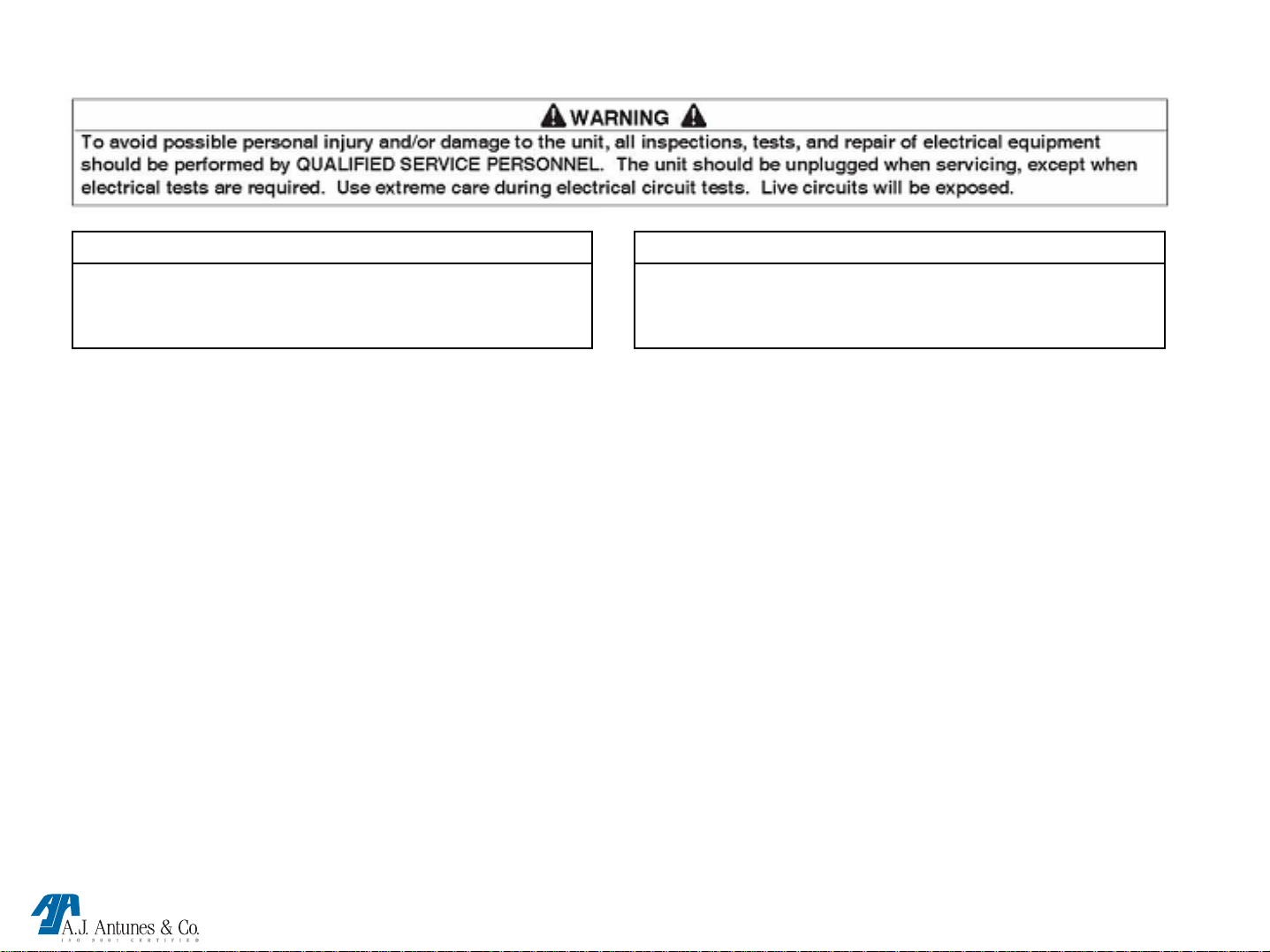
WARNING
Indicates information important to the proper operation of
the equipment. Failure to observe may result in damage to
the equipment
In addition to the warnings and cautions in this manual, use
the following guidelines for safe operation of the unit.
• Read all instructions before using equipment.
• For your safety, the equipment is furnished with a properly
grounded cord connector. Do not attempt to defeat the
grounded connector.
• Install or locate the equipment only for its intend-ed use as
described in this manual. Do not use corrosive chemicals in
this equipment.
• Do not operate this equipment if it has a damaged cord or
plug; if it is not working properly, or if it has been damaged or
dropped.
• This equipment should be serviced by qualified personnel
only. Contact the nearest Roundup authorized service facility
for adjustment or repair.
HOT SURFACE WARNING.
Indicates information important to the handling of
equipment and parts. Failure to observe caution could
result in personal injury.
The following warnings and cautions appear throughout this
manual and should be carefully observed.
• Turn the unit off, disconnect the power source and allow
unit to cool down before performing any service or
maintenance on the unit.
• The procedures in this chapter may include the use of
chemical products. These chemical products will be
highlighted with boldface letters followed by the abbreviated
HCS (Hazard Communication Standard). See Hazard
Communication Standard manual for the appropriate
Material Safety Data Sheets ( MSDS).
• The equipment should be grounded according to local
electrical codes to prevent the possibility of electrical shock.
It requires a grounded receptacle with separate electrical
lines, protected by fuses or circuit breaker of the proper
rating.
• Do not block or cover any openings on the unit.• Do not
immerse cord or plug in water.• Keep cord away from
heated surfaces.• Do not allow cord to hang over edge of
table or counter.
TBS-1X / 2X TECHNICAL MANUAL LAST UPDATE 8-10-04
MANUFACTURING # 9100400, 02, 410, 412
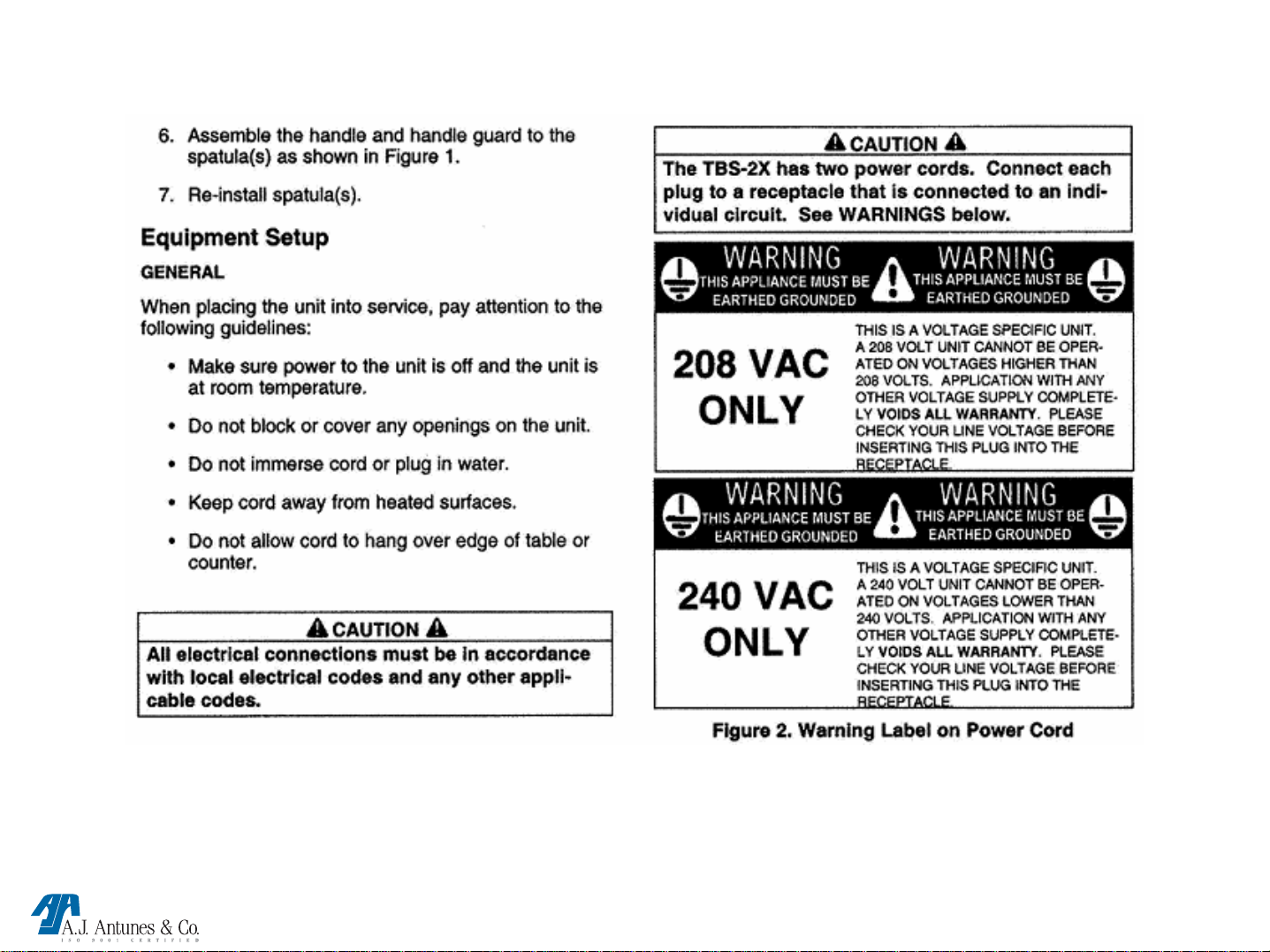
• All electrical connections must be in accordance with local
electrical codes and any other applicable codes.
1060001 8/04
Page 8
IMPORTANT SAFETY INFORMATION
TBS-1X / 2X TECHNICAL MANUAL LAST UPDATE 8-10-04
MANUFACTURING # 9100400, 02, 410, 412
1060001 8/04
Page 9
INSTALLATION
TBS-1X / 2X TECHNICAL MANUAL LAST UPDATE 8-10-04
MANUFACTURING # 9100400, 02, 410, 412
1060001 8/04
Page 10
INSTALLATION CONTINUED
TBS-1X / 2X TECHNICAL MANUAL LAST UPDATE 8-10-04
MANUFACTURING # 9100400, 02, 410, 412
1060001 8/04
Page 11
INSTALLATION CONTINUED
TBS-1X / 2X TECHNICAL MANUAL LAST UPDATE 8-10-04
MANUFACTURING # 9100400, 02, 410, 412
1060001 8/04
Page 12
INSTALLATION CONTINUED
TBS-1X / 2X TECHNICAL MANUAL LAST UPDATE 8-10-04
MANUFACTURING # 9100400, 02, 410, 412
1060001 8/04
Page 13
INSTALLATION CONTINUED
TBS-1X / 2X TECHNICAL MANUAL LAST UPDATE 8-10-04
MANUFACTURING # 9100400, 02, 410, 412
1060001 8/04
Page 14
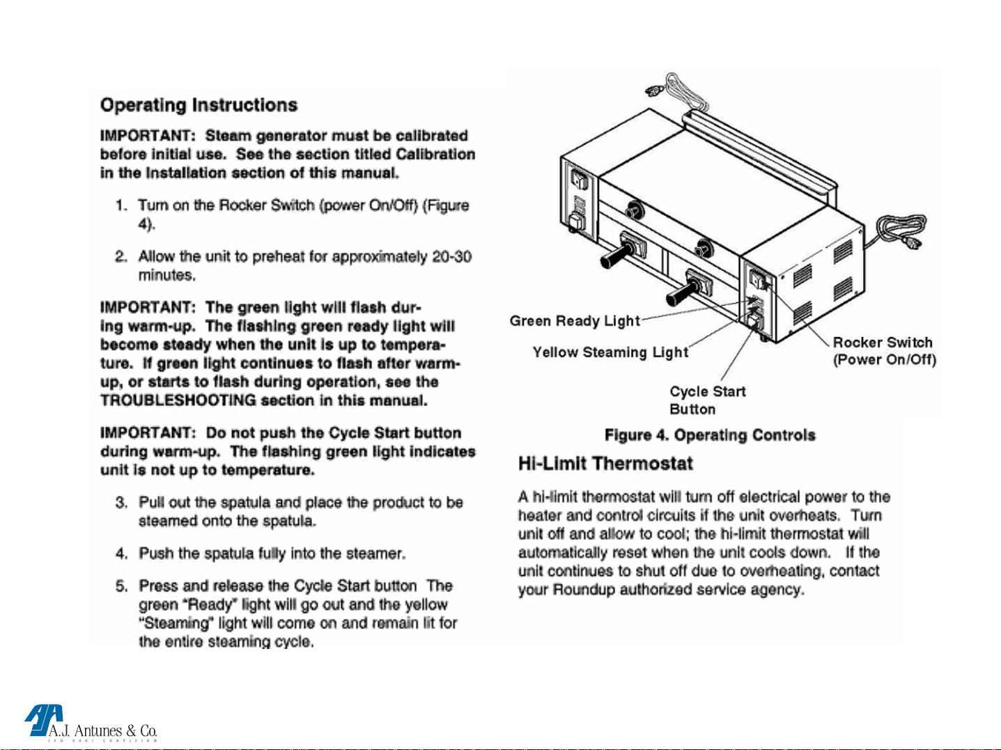
OPERATING INSTRUCTIONS
TBS-1X / 2X TECHNICAL MANUAL LAST UPDATE 8-10-04
MANUFACTURING # 9100400, 02, 410, 412
1060001 8/04
Page 15
OPERATING INSTRUCTIONS CONTINUED
TBS-1X / 2X TECHNICAL MANUAL LAST UPDATE 8-10-04
MANUFACTURING # 9100400, 02, 410, 412
1060001 8/04
Page 16

TBS-X
TECHNICAL THEORY OF OPERATION
When the power switch is on, line voltage flows to the primary side of the step down
transformer. The transformer’s secondary side supplies 12 & 24 VAC to the control board.
Once powered, & provided that the generator temperature is below 380 F, the control board
calls for heat by supplying 7-10 VDC to the solid state relay terminals 3 (+) 4 (-). Once
powered, the relay closes terminals 1 & 2, which allows line voltage to flow to the generator.
As the generator begins to heat up, a type “J” thermocouple monitors the internal generator
temperature. As the heat continues to increase, so does the thermocouple’s DC millivolts.
Once the generator’s temperature rises to 380-420 F (193-215 C), the thermocouple is
generating approximately 10-12 DC millivolts. The control board receives these millivolts &
proceeds to remove the 7-10 VDC to the solid state relay since the heating circuit has now
become satisfied. Then, relay terminals 1 & 2 open up, and the generator stops heating.
The heating circuit will cycle on & off as needed, even at idle. When the cycle start
(Momentary) button is pushed, it signals the control board to initiate a steam cycle.
The control board then supplies 24 VAC to the solenoid valve for approximately one second.
The solenoid opens, and allows a shot of water (approximately 25 ml or ¾ oz) to flow onto
the generator surface for steaming. Since the generator has an oval cover that is secured in
place with a wing nut, the steam is forced downward through the generator steam ports &
onto the product. This control board incorporates several Led’s for status & diagnostic
purposes. See “Led Layout” in Troubleshooting section of the technical manual. An audio
signal will sound for 3 seconds at the end of the cycle. If the heating circuit continues to call
for heat and the generator overheats, an automatic reset hi-limit will trip and open the
generator & transformer circuit. Once it cools down, the hi-limit will reset automatically.
NOTE: If this condition should repeat, the root cause must be determined & corrected.
TBS-1X / 2X TECHNICAL MANUAL LAST UPDATE 8-10-04
MANUFACTURING # 9100400, 02, 410, 412
1060001 8/04
Page 17

Component Description & Function
Power Switch: Double Pole Single Throw, turns the supply voltage On or Off to the unit’s internal line voltage
components.
NOTE: The built in led illuminates when line voltage is present into & out of the switch. If not lit, line voltage is
not present into or out of the switch.
Momentary Switch: Single Pole Single Throw, when pressed & released, it completes a low voltage circuit to the control
board. The control board then initiates a timed steam cycle.
NOTE: Once pressed, the control board locks & will not allow the initiation of another cycle until the first one
concludes.
Stepdown Transformer: Consisting of 2 primary coils & 1 secondary coil, it steps down the incoming supply voltage to
operate the low voltage components (control board , solenoid valve, SS relay input side, momentary s witch).
NOTE: If supply voltage is 208-240, the Primary coils are wired in series. If supply voltage is 120 volts, they are
wired in parallel. NOTE: The secondary coil has a center tap (Terminal 8) that supplies 12 VAC. The two outer
taps, (Terminals 6 & 10) supply 24 VAC.
NOTE: The 12 VAC operates the control board. The 24 VAC operates the solenoid valve circuit.
Control Board: Operates & controls all the timing, steaming, signaling, diagnostic, & heating functions.
NOTE: This control board incorporates 4 Led’s for status & diagnostic p urposes. See “Led Display” in
Troubleshooting Section.
TBS-1X / 2X TECHNICAL MANUAL LAST UPDATE 8-10-04
MANUFACTURING # 9100400, 02, 410, 412
1060001 8/04
Page 18

Component Description & Function (CONTINUED)
SS Relay: A Solid State, Single Pole Single Throw relay that is located at the rear of the unit & mounted on
a heat sink. When its input coil, (Terminals 3 + & 4 - ) is supplied 7-10 VDC by the control board, it allows
the line voltage contacts (Terminals 1 & 2) to close. Once they close, line voltage is supplied to the
generator.
NOTE: SS relays should not be tested/diagnosed with an ohmmeter since this test is not reliable.
Testing/Diagnosing an SS relay should be con d ucted with the steamer & relay powered, and the
use of a voltmeter. If faulty, this relay will permanently fail open (No heat condition) or closed
(Overheating condition). They do not fail intermittently.
NOTE: Terminals 3 (+) & 4 (-) are polarity sensitive. The wiring can be inadvertently switched at the
control board or at the relay if either component is ever replaced. If so, 7-10 VDC will still be
present at the relay, but it will not energize. Therefore, the generator will not heat up. Always verify
per wiring diagram.
Potentiometer (Pot): The Pot is integrated on the control board. It is accessible & adjustable from
underneath the unit. It is used to control the amount of water that is disbursed onto the hot generator
surface for steaming. The Pot regulates the time (In tenths of a second), that the solenoid valve is being
supplied 24 VAC by the control board.
NOTE: Adjustable Range is .5 to 1.5 seconds.
TBS-1X / 2X TECHNICAL MANUAL LAST UPDATE 8-10-04
MANUFACTURING # 9100400, 02, 410, 412
1060001 8/04
Page 19

Component Description & Function (CONTINUED)
Generator: Also known as a heating plate, it is an oval aluminum casting consisting of a permanently integrated
heating element. When powered, it generates heat to convert a shot of water (approximately ¾-1oz 25-30 ml) into
steam instantaneously.
NOTE: The generators are dual voltage 208-240 volts and can operate on either voltage.
NOTE: All generators are artificially seasoned (Limed) at the factory. A mixture of water, baking soda, & lime,
is poured onto the generator surface to steam away & formulate a thin layer of calcium buildup. A thin layer
is always needed for proper steaming characteristics. See “Monthly Maintenance” section.
Generator Lid: An oval shape, gasket less lid that is secured onto the generator with a wing nut. Allows the steam to
be forced down through the generator steam ports, & onto the product.
Generator Diffuser Plate: An oval plate with many small orifices. Helps contain & prevent loose particles from being
directed onto the food product.
Chimney: Located at the rear of the unit, it allows excessive steam in the food compartment to exit the steamer from
the rear.
Thermocouple: A type “J” consisting of 2 wires, Red (-) & White (+). One side plugs into the control board & the
other is inserted into a hole in the generator. As it monitors the internal generator temperature, it generates & relays
DC millivolts to the control board
NOTE: At the control board, the thermocouple connector plugs into 3 male pins. The center pin is positive
(+) & MUST always align with the white wire. The two outer pins are negative (-) & either one must align with
the red wire.
TBS-1X / 2X TECHNICAL MANUAL LAST UPDATE 8-10-04
(See Millivolt Chart next page).
MANUFACTURING # 9100400, 02, 410, 412
1060001 8/04
Page 20

THERMOELECTRIC VOLTAGE IN MILLIVOLTS
TYPE “J” THERMOCOUPLE (READINGS + OR – 1 MILLIVOLT)
° F MV ° F MV ° F MV
300 7.9
310 8.2
320 8.5
330 8.8
340 9.1
350 9.4
360 9.7
370 10.1
380 10.4
390 10.7
400 11.0
410 11.3
420 11.6
430 11.9
440 12.2
450 12.5
460 12.8
470 13.1
480 13.4
490 13.8
500 14.1
510 14.4
520 14.7
530 15.0
540 15.3
550 15.6
560 15.9
570 16.2
580 16.5
590 16.8
600 17.1
TBS-1X / 2X TECHNICAL MANUAL LAST UPDATE 8-10-04
MANUFACTURING # 9100400, 02, 410, 412
1060001 8/04
Page 21

Component Description & Function (CONTINUED)
Solenoid Valve: A normally closed 24 VAC water valve that is electrically operated for approximately one
second by the control board during a steam cycle.
NOTE: The “IN” & “OUT” markings on the valve bo dy must correspond with water flow, otherwise, the
valve will leak through. If the valve is installed correctly and leaking through, debris/speck has
become lodged within the plunger & body area. Disassembly & cleaning of the plunger area is simple.
See “Parts Testing & Replacement Procedure” section. Also see “Potentiometer” on this page.
Hi-Limit: A round ceramic bodied, disc type, normally closed temperature switch that monitors the air gap
temperature between the chassis & the generator. If the heating circuit fails & runs away, the hi-limit will trip
(Generally between 600F-700 F) & open the generator & transformer circuit.
NOTE: If this type of hi-limit trips, it will reset automatically once it cools. If at any time a hi-limit trips,
the root cause must be determined & corrected.
TBS-1X / 2X TECHNICAL MANUAL LAST UPDATE 8-10-04
MANUFACTURING # 9100400, 02, 410, 412
1060001 8/04
Page 22

Component Description & Function (CONTINUED)
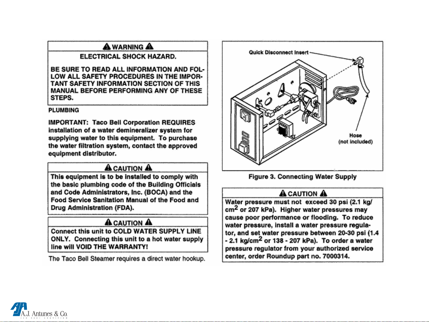
Quick Disconnect Female: Mounted at the rear of the unit, it engages with a male fitting to form a leak proof union that
allows water flow to the inlet side of the solenoid valve. The union can be easily seperated by pressing the quick release
tab on the fitting.
Quick Disconnect Male: A male elbow fitting that engages with the female fitting to allow water flow. It contains a spring
loaded “white” extended nylon tip (A retracting internal flow valve). The barbed end of the fitting is attached to the
nylon braided water supply line while the side with the “white” extended nylon tip is to be fully pushed into the female
fitting until a “Click” is heard.
NOTE: The “Click” indicates the fitting is locked into position & the extended nyl o n tip has retracted to allow
water flow.
Audio Signal: An audio device located at the bottom of the control board. At the completion of steam cycle, the control
board supplies approximately 10-15 VDC to it for 3 seconds.
NOTE: The signal can be replaced separately if it fails. It can be tested with a 9 VDC battery.
Green “Ready” & Yellow “Steam” lights: Located at the front of the unit and attached to the control board. When the
green light blinks, it indicates the generator is not up to temperature, therefore, the unit should not be cycled during this
time. When the green light is steadily on, it indicates the generator is up to operating temperature & ready for use. When
the Yellow light is on, it indicates the unit is in a timed steam cycle.
NOTE: These lights are polarity sensitive. If replacement is needed, they must be installed properly. Long lead is
positive (+) & the shorter lead is negative (-).
TBS-1X / 2X TECHNICAL MANUAL LAST UPDATE 8-10-04
MANUFACTURING # 9100400, 02, 410, 412
1060001 8/04
Page 23

TOOLS & ITEMS REQUIRED FOR PROPER TROUBLESHOOTING,
MAINTENANCE & REPAIR
(VOM) Volt Ohm Meter (digital or analog)
DC millivolt meter (unless integrated into VOM)
Clamp type amp meter (digital or analog)
Flat blade screwdriver ¼ ", 3/16"
Open end wrench ½"
Adjustable wrench 6"
¼“ ratchet and socket
Channel locks
Wire cutter, crimper, stripper
Wire brush
Needle nose pliers.
Temp meter with wire type thermocouple or surface type pyrometer
(must be able to read 500° F (260 °C) or more
Water calibration kit #7000150 (included with every unit)
Baking soda & powdered lime & mixing container
Teflon tape
Hi temp Dow Corning #736 RTV
TBS-1X / 2X TECHNICAL MANUAL LAST UPDATE 8-10-04
MANUFACTURING # 9100400, 02, 410, 412
1060001 8/04
Page 24

MAINTENANCE
WARNING
Turn the unit off, disconnect the power source and allow the unit to
cool down before performing any service or maintenance on the
unit. The TBS-2X has two power cords. Make sure both cords are
disconnected
CAUTION
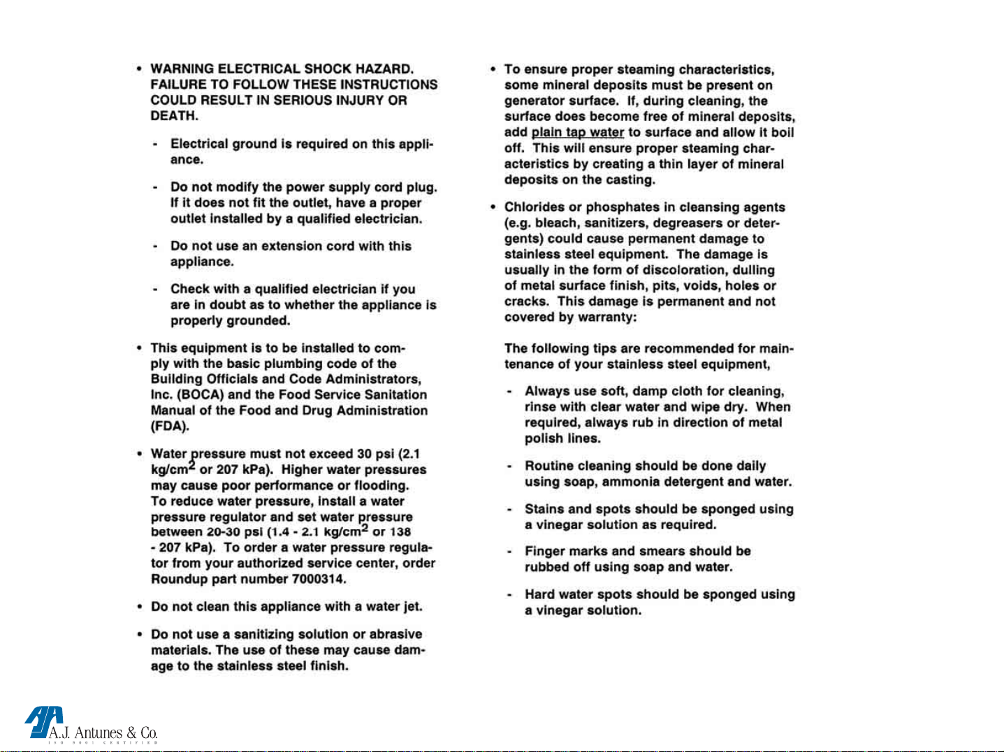
Chlorides or phosphates in cleansing agents (e.g. bleach, sanitizers,
degreasers or detergents) could cause permanent damage to
stainless steel equipment. The damage is usually in the form of
discoloration, dulling of metal surface finish, pits, voids, holes or
cracks. This damage is permanent and not covered by warranty.
The following tips are recommended for maintenance of your
stainless steel equipment:
•Always use soft, damp cloth for cleaning, rinse with clear water
and wipe dry. When required, always rub in direction of metal
polish lines.
•Routine cleaning should be done daily using soap, ammonia
detergent and water.
•Stains and spots should be sponged using a vinegar solution.
•Finger marks and smears should be rubbed off using soap and
water.
•Hard water spots should be sponged using a vinegar solution.
CAUTION
Do not use a sanitizing solution or abrasive materials. The use of
these may cause damage to the stainless steel finish.
CAUTION
If a chemical cleaner is used, be sure it is safe to use on cast
aluminum. Observe all precautions and warnings on product label.
NOTE: Frequency of cleaning is determined by water
conditions, usage and water filter systems.
FIGURE 5
Daily Cleaning
1.Turn off Rocker Switch (power On/Off), unplug the power
cord(s) and allow the unit to cool down before proceeding
2.Check the water quick disconnect fitting and all hose clamp
connections for leakage. If leakage is apparent, tighten all
clamps or replace part if required.
3.Remove the Top Cover, spatula(s) and Liner(s) (Figure 5).
4.Remove chimney from rear of unit by sliding upward and
away from unit (Figure 5). Clean the Top Cover, Spatula(s),
Liner(s) and chimney in hot soapy water, rinse in clear water
and allow to dry.
5.Clean the chamber(s) of any product spills.
6.Clean entire unit with a clean, hot, damp cloth (not dripping
wet) and wipe dry.
7.Re-install chimney, liner(s) and spatula(s) and Top Cover.
TBS-1X / 2X TECHNICAL MANUAL LAST UPDATE 8-10-04
MANUFACTURING # 9100400, 02, 410, 412
1060001 8/04
Page 25

MAINTENANCE CONTINUED
Monthly Maintenance
Your steamer utilizes an open steam generator. Water
sprayed onto the generator surface flashes into steam
immediately, but the minerals in the water do not steam,
they stay on the generator surface. A small amount of
mineral deposits are needed for proper operation, but a
build-up of excessive mineral deposits causes poor
steaming efficiency, excessive moisture (wet steam)
and will eventually severely retard the steaming action
completely.
Cleaning Steam Generator
1. Turn the Rocker Switch (power On/Off) to OFF,
unplug the power cord(s) and allow the unit to
Cool down before proceeding.
2. Remove top cover from unit.
3. Remove wing nut and Generator cover (Figure 5).
4. Remove Steam Diffuser.
5. Examine all Generator steam ports (Figure 5).
If mineral deposits have formed, place a flat blade
screwdriver or wire brush into openings. Use a
twisting motion to scrape openings clean.
NOTE: If the mineral deposits come off in “flakes”
or in layers, build-up is excessive.
6.Use a brass or stainless steel wire brush and
small scraper to loosen and remove excessive
deposits from the generator surface. If deposits
are still excessive and/or difficult to remove, go to
next step
7. Pour delimer solution (not supplied) onto the
generator surface. Be sure to follow the delimer
manufacturer’s directions for proper mixture and
use; it must be safe to be used on aluminum
TBS-1X / 2X TECHNICAL MANUAL LAST UPDATE 8-10-04
MANUFACTURING # 9100400, 02, 410, 412
CAUTION:
If a chemical cleaner/delimer is used, be sure it is safe
to USE on cast aluminum. Observe all precautions
and warnings on the product label.
8. Remove the delimer solution from the generator
and rinse with clear water to remove traces of delimer.
9. Clean the following parts in hot, detergent water,
then rinse in clear water and allow to dry:
spatula chimney liner
top cover diffuser generator
10. Clean Steam Chamber free of any product spills.
11. Clean unit surface with a hot, clean, damp cloth
(not dripping wet) and wipe dry.
12. Re-install all parts and fasten the generator cover.
IMPORTANT: To ensure proper steaming
characteristics, some mineral deposits must be
present on generator surface. If during cleaning, the
surface does become free of mineral deposits (bare
aluminum, add plain tap water
boil off.
to surface and allow to
1060001 8/04
Page 26

MAINTENANCE CONTINUED
IMPORTANT: In soft water areas, it may be necessary
to add a small amount of lime to generator
surface to “season” it. This will ensure proper
steaming characteristics by producing a thin
coating of mineral deposits on the surface.
Seasoning mixture consists of 75 ml. baking
soda, 75 ml. lime, and 1 gallon water. Pour ¼”
deep of seasoning mixture onto hot generator.
After mixture is converted to steam, the
remaining loose power can be removed.
13. Plug in power cord(s) and water line(s).
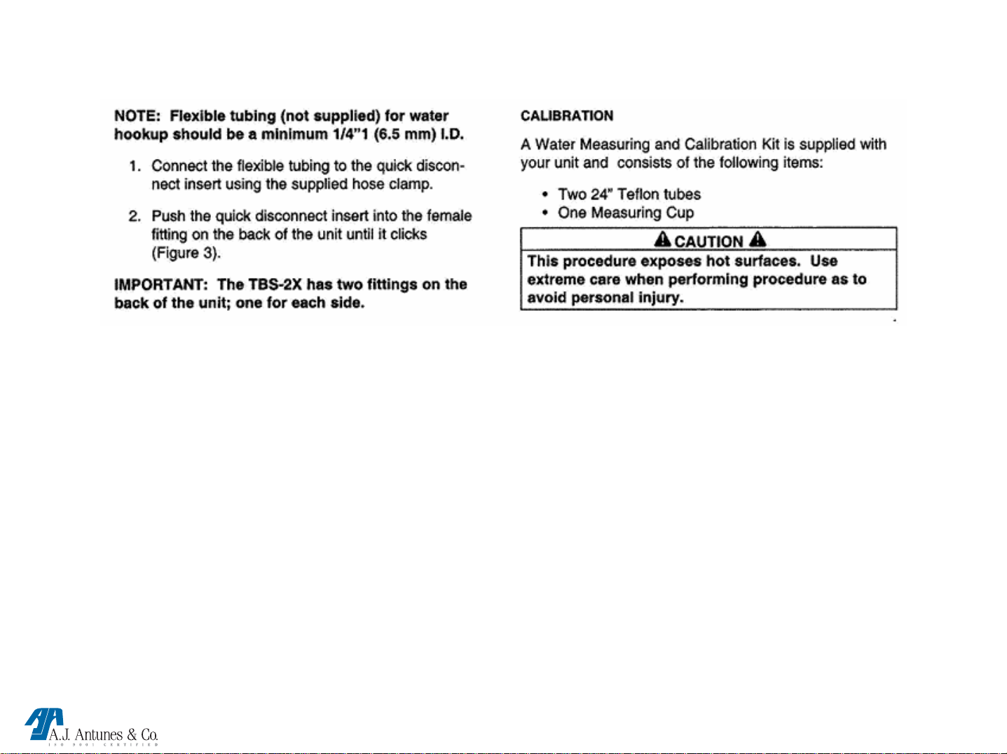
CALIBRATION
A Water Measuring and Calibration Kit is supplied with
your unit and consists of the following items:
• Two 24” Teflon tubes
• O ne measuring cup
WARNING
This procedure exposes hot surfaces. Use extreme
care when performing procedure to avoid personal
injury.
NOTE: If tube will not push in easily, the hole could
be clogged with mineral deposits. Use a flatbladed screwdriver to scrape deposits out of
the holes.
4. Put other end of calibration tubes into the calibration
cup (Figure 7).
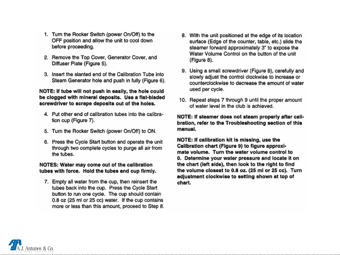
1. Turn the Rocker Switch (power On/Off) to OFF and
allow the unit to cool down before proceeding.
2. Remove the top cover, generator cover and diffuser
plate (Figure 5).
3. Insert the slanted end of the calibration tube into
steam generator hole and push in fully (Figure 6).
TBS-1X / 2X TECHNICAL MANUAL LAST UPDATE 8-10-04
MANUFACTURING # 9100400, 02, 410, 412
1060001 8/04
Page 27

MAINTENANCE CONTINUED
5. Turn the Rocker Switch (power On/Off) to on.
6. Press the Cycle Start button and operate the unit
through two complete cycles to purge all air from the
tubes.
NOTE: Water may come out of the calibration tubes with force. Hold the tubes
and cup firmly.
7. Empty all water from the cup, then reinsert the tubes back into the cup.
Press the Cycle Start button to run one cycle.
The cup should contain 0.8 oz. (25 ml or 25 cc) If it contains more or less of
this amount, proceed to step 8
8. With the unit positioned at the end of its location surface (edge of the counter,
table, etc) slide the steamer forward approximately 3” to expose the Water
Volume Control on the bottom of the unit (Figure 8).)
9. Using a small screwdriver, carefully and slowly adjust the control clockwise to
increase or counterclockwise to decrease the amount of water used per cycle.
10. Repeat steps 7 – 9 until the proper amount of water level in the cup is
achieved.
NOTE: If steamer does not steam properly after calibration, refer to the
Troubleshooting section of this manual.
Figure 8
NOTE: If calibration kit is missing, use the Calibration Chart (Figure 9) to figure
approximate volume. Turn the water volume control to 0. Determine your
water pressure and locate it on the chart (left side), then look to the right to
find the volume closest to 0.8 oz. (25 ml or 25 cc). Turn adjustment
clockwise to setting shown at top of chart.
TBS-1X / 2X TECHNICAL MANUAL LAST UPDATE 8-10-04
MANUFACTURING # 9100400, 02, 410, 412
Figure 9
1060001 8/04
Page 28

TROUBLE SHOOTING
TROUBLE SHOOTING
LED LAYOUT
HEAT SOLENOID AUDIO THERMOCOUPLE
1
RED GREEN YELLOW YELLOW
42 3
This control board has 4 LED’S for status and diagnostic
purposes
RED (Heat): When Lit, indicates the unit is calling for heat by
supplying 7-10 VDC to the solid state relay. When off,
indicates the unit is satisfied.
Green (Solenoid): When lit, indicates that 24 VAC is being
supplied to open the solenoid.
NOTE: This LED is only lit for approximately 1 second.
Yellow (Audio): When lit, indicates that 10-15 VDC is being
supplied to the Audio Signal. The Audio Signal will sound for
3 seconds.
Yellow (Thermocouple): When lit, indicates that the
thermocouple is disconnected or “open” and unit will not call
for heat.
NOTE: LED should not be lit during normal operation.
TBS-1X / 2X TECHNICAL MANUAL LAST UPDATE 8-10-04
MANUFACTURING # 9100400, 02, 410, 412
1060001 8/04
Page 29

TROUBLE SHOOTING
TROUBLE SHOOTING
PROBLEM: POSSIBLE CAUSE: RESOLUTION:
Unit steams, but
requires 2 or more
cycles to melt cheese.
Generator surface temperature is
too low
Insufficient or excessive calcium
deposits on Generator surface.
Generator Cover is warped or loose. Verify that the Generator Cover wingnut is tight.
Low water pressure.
Water Volume Adjustment is set too
low.
Verify Generator surface temperature to be
380 - 420°F.
Verify Generator surface has a thin calcium
coating for proper steaming. Refer to the
Maintenance section of the owners manual.
If noticable steam excapes around the
Generator Cover.
Replace generator cover
Verify Water Pressure regulator is set to 20-30
psi, adjust accordingly.
Calibrate unit for proper water volume. Refer to
the Maintenance section of the owners manual.
Generator Steam Ports are
restricted.
Generator surface is bare. Generator surface must have a thin calcium
TBS-1X / 2X TECHNICAL MANUAL LAST UPDATE 8-10-04
MANUFACTURING # 9100400, 02, 410, 412
Verify that the Steam Ports are not restricted.
Clean accordingly.
coating for proper steaming. Refer to the
Maintenance section of the owners manual.
1060001 8/04
Page 30

TROUBLE SHOOTING
TROUBLE SHOOTING
PROBLEM: POSSIBLE CAUSE: RESOLUTION:
Unit heats but does not
steam.
Low or no water pressure in water
line.
Solenoid Valve Coil is “open.” Verify that there are 8-20 Ohms on the coil.
Control Board inoperable or
problem-atic.
Quick Disconnect is not fully
engaged at rear of unit or is
damaged.
Remove the Quick Disconnect Insert from the
rear of the unit. While holding into an empty
cup, press the white plastic tip. Strong steady
water flow should be noted. If so, re-engage
firmly into the unit. If not present, or low
pressure, contact your maintenance person or
plumber.
Verify 24 VAC to Solenoid Valve Coil when the
Cycle Start button is pushed.
NOTE: Wires must be left attached to valve and
voltage is only read for a split second.
If there is no voltage, replace the Control Board
Remove and re-engage the Quick Disconnect
firmly until a “click” is heard. Replace if
damaged.
Excessive condensation
in Food Compartment.
Cycle Start switch inoperable or
problematic.
Water pressure is too high.
Water Volume Adjustment is set too
high.
TBS-1X / 2X TECHNICAL MANUAL LAST UPDATE 8-10-04
MANUFACTURING # 9100400, 02, 410, 412
Verify continuity when the switch is pressed. If
there is no continuity replace the switch.
Verify Water Pressure Regulator is set to 20-30
psi, adjust accordingly.
Calibrate unit for proper water volume. Refer to
the Maintenance section of the owners manual.
1060001 8/04
Page 31

TROUBLE SHOOTING
TROUBLE SHOOTING
PROBLEM: POSSIBLE CAUSE: RESOLUTION:
unit only leaks water when pow- solenoid valve is leaking due disassemble the solenoid valve and clean
ered off. to debris trapped inside the out the plunger. reassemble and test. if the
plunger. a leak is still present, replace the solenoid
valve.
solenoid valve is installed if the solenoid valve was replaced, verify
incorrectly. that the “in” and “out” labels on t he valve
correspond to the water flow.
unit only leaks water when pow- control board inoperable or
ered on. problematic.
if 24 vac is measured across the solenoid
valve coil for over 2 seconds (with wires
still attached to the coil).
Replace the control board
no heat and the green ready light
flashes continuously
TBS-1X / 2X TECHNICAL MANUAL LAST UPDATE 8-10-04
generator is “open.”
solid state relay not closing
MANUFACTURING # 9100400, 02, 410, 412
verify that the resistance is in a range of
13 – 18 Ohm’s.
Replace if the generator fails test
verify that there is 7-10 vdc on relay
terminals 3 (+) 4(-). if present, check for
line voltage across relay terminals 1 and 2.
if present, replace the relay
1060001 8/04
Page 32

TROUBLE SHOOTING
TROUBLE SHOOTING
PROBLEM: POSSIBLE CAUSE: RESOLUTION:
Control Board inoperable or Verify that there is 7-10 VDC on terminals
problematic. T5 & T3. If not present, replace the Control
Board.
Loose, burnt, or broken wires Repair or replace wires.
in heater circuit.
Circuit is wired incorrectly. Verify that all wiring matches the Wiring
Diagram in this manual.
Unit does not operate, power switch Unit unplugged. Plug Power Cord into the appropriate outlet.
is on but light is off. Circuit breaker is off. Reset the circuit breaker.
Power Cord defective or inop- Check for continuity.
erable.
Power Switch defective or
inoperable.
Green “Ready” light and “Yellow” Hi-Limit is tripping because of Verify that the generator surface temperasteaming light turn on and off inter- an overheating Generator.
mittently.
Hi-Limit is tripping prematurely. replace the Hi-Limit thermostat.
TBS-1X / 2X TECHNICAL MANUAL LAST UPDATE 8-10-04
MANUFACTURING # 9100400, 02, 410, 412
ture is between 380-420° F. If the tempera-
ture is above 420° F, contact your mainte-
nance person or Authorized Service Agency.
If the Hi-Limit trips within 380-420° F,
1060001 8/04
Page 33

PARTS TESTING AND
REPLACEMENT PROCEDURE
TBS-1X / 2X TECHNICAL MANUAL LAST UPDATE 8-10-04
MANUFACTURING # 9100400, 02, 410, 412
1060001 8/04
Page 34

POWER SWITCH
SEE POWER SWITCH UNDER “COMPONENT DESCRIPTION & FUNCTION BEFORE PROCEEDING
TESTING POWER SWITCH
Disconnect wires to isolate switch.
Turn switch to the “On” position. Verify continuity across
terminals 1 & 2, then 4 & 5. Next, turn switch to the “Off” position.
Reading should now be infinity.
Replace if fails test.
4 5
Replacement Procedures
• Disconnect power switch wires (Mark for reinstallation).
• Squeeze locking tabs inward & push switch out towards
front of unit.
• Snap new switch into place until flush.
• Reinstall wiring onto switch.
• Test unit for proper operation.
TBS-1X / 2X TECHNICAL MANUAL LAST UPDATE 8-10-04
MANUFACTURING # 9100400, 02, 410, 412
1
2
1060001 8/04
Page 35

MOMENTARY SWITCH
SEE MOMENTARY SWITCH UNDER “COMPONENT DESCRIPTION & FUNCTION BEFORE PROCEEDING
TESTING MOMENTARY SWITCH
Disconnect wires to isolate switch.
Press & hold switch in. Verify continuity across both
terminals. Next, release switch. Reading should now be infinity.
Replace if fails test.
Replacement Procedures
• Disconnect switch wires.
• Squeeze locking tabs inward & push switch
out towards Front of unit.
• Snap new switch into place until flush.
• Reinstall wiring onto switch.
• Test unit for proper operation
TBS-1X / 2X TECHNICAL MANUAL LAST UPDATE 8-10-04
MANUFACTURING # 9100400, 02, 410, 412
1060001 8/04
Page 36

STEPDOWN TRANSFORMER
SEE STEP DOWN TRANSFORMER UNDER “COMPONENT DESCRIPTION & FUNCTION BEFORE PROCEEDING
TESTING STEPDOWN TRANSFORMER
Disconnect wires to isolate transformer coils.
Terminals 1 & 2 (15-19 ohms)
Terminals 4 & 5 (17-23 ohms)
Terminals 6 & 10 (0.6 ohms)
Terminals 6 & 8 (0.3 ohms)
Terminals 8 & 10 (0.3 ohms)
All readings +/- 10% Replace if any coil fails test.
10
6
8
1
2
4
5
Replacement Procedures
• Disconnect transformer wires (Mark for reinstallation).
• Remove the 2 screws beneath the transformer.
• Install new transformer & secure into place with screws.
• Reinstall the wiring onto transformer.
• Test unit for proper operation.
TBS-1X / 2X TECHNICAL MANUAL LAST UPDATE 8-10-04
MANUFACTURING # 9100400, 02, 410, 412
1060001 8/04
Page 37

CONTROL BOARD
CONTROL BOARD
SEE CONTROL BOARD UNDER “COMPONENT DESCRIPTION & FUNCTION BEFORE PROCEEDING
TESTING CONTROL BOARD
Control Board must be tested while powered up
(See Technical Theory of Operation).
Check for proper VAC/VDC input & output.
Replace if it fails any of its functions.
PINS
Replacement Procedures
• Disconnect control board wiring & thermocouple
(Mark for reinstallation).
• Remove 4 nuts & cautiously pull the control board
away from front panel.
• Align new control board with the short & long Led
pins then secure with the nuts.
• Reinstall the wiring & thermocouple onto control board.
Allow unit to heat up 15 minutes.
• Calibrate unit for proper water volume disbursement
(See Monthly Maintenance Section).
• Test unit for proper operation.
TBS-1X / 2X TECHNICAL MANUAL LAST UPDATE 8-10-04
MANUFACTURING # 9100400, 02, 410, 412
1060001 8/04
Page 38

SOLID STATE RELAY
SEE SOLID STATE RELAY UNDER “COMPONENT DESCRIPTION & FUNCTION BEFORE PROCEEDING
TESTING SS RELAY
To determine if relay contacts are stuck closed
(unit overheating):
Disconnect RED wire from relay terminal 3 (+).
Clamp an amp meter onto the black wire at relay terminal
1 or 2. Is there any amp draw? If yes, replace relay.
To determine if relay contacts are stuck open (unit
not heating):
Ensure the control board & relay are wired per the wiri ng
diagram. Is 7-10 VDC present at relay terminals 3 (+) &
4 (-)? If yes, is line voltage present across the two
generator terminals? If no, replace relay.
1
4-
2
3+
Replacement Procedures
• Disconnect the relay wiring (Mark for reinstallation).
• Remove the two mounting screws & relay.
• Install new relay with thermal compound
(If included in kit).
• Reinstall wiring onto relay.
• Test unit for proper operation.
TBS-1X / 2X TECHNICAL MANUAL LAST UPDATE 8-10-04
MANUFACTURING # 9100400, 02, 410, 412
1060001 8/04
Page 39

POTENTIOMETER (POT)
SEE POTENTIOMETER UNDER “COMPONENT DESCRIPTION & FUNCTION BEFORE PROCEEDING
TESTING POTENTIOMETER (Pot)
The pot’s metal stem should only rotate from 7-5 o’clock
& vice versa.
If metal stem rotates continuously, replace control board.
Replacement Procedures
• Follow the control board replacement
TBS-1X / 2X TECHNICAL MANUAL LAST UPDATE 8-10-04
POT
MANUFACTURING # 9100400, 02, 410, 412
1060001 8/04
Page 40

GENERATOR
SEE GENERATOR UNDER “COMPONENT DESCRIPTION & FUNCTION BEFORE PROCEEDING
TESTING GENERATOR
Disconnect wires to isolate generator.
Verify the resistance is in a range of 13 to 18
ohm’s.
Check from each terminal to ground using at
least a 20M scale. Reading should be infinity.
Replace if fails either test.
Replacement Procedures
• Disconnect generator wiring.
• Loosen bracket & remove thermocouple.
• Remove compression nuts & steel tubes
from the brass elbow & “T” fitting.
NOTE: Flexing the Teflon tubes may be required.
• Unscrew (CCW) the brass elbow & fitting along with the
Teflon tubes from the generator.
• Remove generator wing nut, lid, & diffuser plate.
• Remove the generator’s top four corner
retainers & screws.
• Remove the generator’s top 3 setscrews.
• Cautiously, push the generator up & out of the chassis.
TBS-1X / 2X TECHNICAL MANUAL LAST UPDATE 8-10-04
MANUFACTURING # 9100400, 02, 410, 412
1060001 8/04
Page 41

GENERATOR (CONTINUED)
NOTE: Extra effort may be needed as generator is siliconed
onto the chassis.
Remove remaining dried silicone from chassis.
Apply 1/8” bead of red hi-temperature silicone (Supplied in kit)
onto the chassis the underside of the generator.
NOTE: Failure to apply silicone will allow steam to enter the
Electrical compartment.
Seat new generator in place & secure with new setscrews.
NOTE: Replacement generator will have artificial lime
deposits on it that are required for proper steaming
characteristics.
• Remove any excess silicone & smooth to a neat finish.
• Apply teflon tape to the threads on the Teflon tubes & screw
into the generator until snug.
• Reinstall the steel tubes, compression nuts, & secure.
• Reinstall wiring, thermocouple, & secure.
• Reinstall & secure corner retainers with silicone & screws.
• Allow unit to heat 15 minutes.
• Run several cycles & check for leaks within electrical
compartment. Repair if needed.
• Calibrate the unit for proper water volume disbursement
(See Monthly Maintenance).
• Reinstall diffuser plate, lid, wing nut, & service panel.
NOTE: Silicone must be allowed to cure 12-24 hours
before customer places unit into use.
TBS-1X / 2X TECHNICAL MANUAL LAST UPDATE 8-10-04
MANUFACTURING # 9100400, 02, 410, 412
1060001 8/04
Page 42

GENERATOR LID
SEE GENERATOR LID UNDER “COMPONENT DESCRIPTION & FUNCTION BEFORE PROCEEDING
TESTING GENERATOR LID
Ensure the wing nut is tight.
Does noticeable steam leak out the perimeter of the
cover?
If yes, remove cover, check it for flatness, & observe its
underside.
Does the outer ½” perimeter contain noticeable calcium
buildup? If yes, replace cover.
NOTE: Calcium buildup at perimeter indicates that steam
is leaking out from there. If perimeter is shiny, it indicates
that steam is not leaking.
NOTE: Gaskets are not used in TBS-X series.
½"
Replacement Procedures
• Remove wing nut & lid.
• Install new lid & secure with wing nut.
• Test unit for proper operation.
TBS-1X / 2X TECHNICAL MANUAL LAST UPDATE 8-10-04
MANUFACTURING # 9100400, 02, 410, 412
GOOD LID IS SHOWN
1060001 8/04
Page 43

TYPE “J” THERMOCOUPLE
SEE THERMOCOUPLE “COMPONENT DESCRIPTION & FUNCTION BEFORE PROCEEDING
TESTING TYPE ”J” THERMOCOUPLE
To test thermocouple for continuity: Unplug thermocouple from
control board to isolate it.
At room temperature, verify 2-3 ohms across red & white wire.
Replace if fails test.
To determine if an “overheating” or “under heating
condition” is caused by faulty thermocouple: Preheat unit for
15 minutes then monitor the generator’s surface, or internal
temperature. Next, unplug the thermocouple from the control
board. Set your VOM to the VDC scale, 50-200 MV (millivolt)
range. Using the provided millivolt chart, determine if the
thermocouple is generating the proper DC millivolts (+/- 1.0
millivolt) at the indicated temperature.
Quick Tip: If the unit is under heating, the DC millivolts being
generated will be much higher than what they should. If the unit is
overheating, the DC millivolts being generated will be much lower
than what they should be.
Replace if fails test.
Replacement Procedures
Disconnect thermocouple from control board.
Loosen retainer bracket screw & remove from generator hole.
Install new thermocouple & secure to generator & control board.
Test unit for proper operation.
TBS-1X / 2X TECHNICAL MANUAL LAST UPDATE 8-10-04
MANUFACTURING # 9100400, 02, 410, 412
1060001 8/04
Page 44

Hi-Limit
See Hi-limit under “Component Description & Function” before proceeding
To test for continuity: Disconnect wires to isolate hi-limit.
Verify continuity across the terminals.
Replace if fails test.
To determine if hi-limit is tripping prematurely: Monitor
the generator’s surface or internal temperature.
Does hi-limit trip below 450 F (232 C)? If yes, replace hilimit.
To determine if hi-limit is tripping too late, or not at all:
Short relay
overheating condition).
Monitor the generator’s surface or internal temperature.
Does the temperature exceed 700 F (371 C)? Is the
generator still drawing amperage? If yes, replace hi-limit.
NOTE: Reinstall any removed wiring to their original
terminals.
terminals 1 & 2 together (This simulates an
Replacement Procedures
Disconnect hi-limit wires.
Remove the two mounting screws & hi-limit.
Install new hi-limit & secure with screws.
Reinstall wiring onto hi-limit.
Test unit for proper operation.
TBS-1X / 2X TECHNICAL MANUAL LAST UPDATE 8-10-04
MANUFACTURING # 9100400, 02, 410, 412
2
1
1060001 8/04
Page 45

SOLENOID VALVE
See Solenoid Valve under “Component Description & Function” before proceeding.
To test the solenoid valve coil: Disconnect wires to isolate solenoid
valve. Verify 8-20 ohms.
Replace if fails test.
To determine if solenoid valve is leaking through: Turn power off &
disconnect water line from rear.
Dry up any water that is present on the generator surface.
Once dry, reconnect the water line ONLY.
Does water begin to slowly flow onto the generator surface?
If yes, disassemble & clean out solenoid valve plunger.
If still leaks.
Replace solenoid valve.
TBS-1X / 2X TECHNICAL MANUAL LAST UPDATE 8-10-04
MANUFACTURING # 9100400, 02, 410, 412
1060001 8/04
Page 46

SOLENOID VALVE
See Solenoid Valve under “Component Description & Function” before proceeding.
To Clean: Remove top nut then slide coil assembly off. Secure the valve body with channel locks.
If the valve stem is slotted at the top, loosen & remove the stem with a sturdy screw driver.
If it is not slotted, you will need the special hex nut with locking pins.
Remove the plunger, spring, o’ring. With a cloth, gently clean out the plunger & body area.
Generally, the debris/speck found will be small. Reassemble items & recheck.
Replace if still leaks.
TBS-1X / 2X TECHNICAL MANUAL LAST UPDATE 8-10-04
MANUFACTURING # 9100400, 02, 410, 412
1060001 8/04
Page 47

SOLENOID VALVE
See Solenoid Valve under “Component Description & Function” before proceeding.
Replacement Procedures
Disconnect solenoid valve wires.
Remove compression nuts & steel tubes from the brass elbow & “T” fitting.
NOTE: Flexing the Teflon tubes may be required to ease nut & tube removal.
Remove the two rear quick disconnect screws.
Remove the solenoid/QD assembly.
Unscrew the QD from the solenoid valve body.
NOTE: Vice may be required.
Thread the QD into the new solenoid valve body.
NOTE: Apply thread sealant onto threads.
Reinstall solenoid/QD assembly & secure with screws.
Reinstall the steel tubes, compression nuts, & secure.
Allow unit to preheat 15 minutes.
Run several cycles & check for leaks within electrical compartment. Repair if needed. Test unit for proper operation.
TBS-1X / 2X TECHNICAL MANUAL LAST UPDATE 8-10-04
MANUFACTURING # 9100400, 02, 410, 412
1060001 8/04
Page 48

QUICK DISCONNECT (FEMALE)
See Quick Disconnect Female under “Component Description & Function” before proceeding
The Female QD is generally trouble free.
If the locking mechanism (Tab, spring, pin)
are missing or damaged.
The female QD must be replaced.
Replacement Procedures
Disconnect the solenoid valve wires.
Remove compression nuts & steel tubes from
the brass elbow & “T” fitting.
NOTE: Flexing the Teflon tubes may be
required to ease nut & tube removal.
Remove the two rear quick disconnect screws.
Remove the solenoid/QD assembly.
Unscrew the QD from the solenoid valve body.
NOTE: Vice may be required.
Thread new QD into the solenoid valve body.
NOTE: Apply thread sealant onto threads.
Reinstall solenoid/QD assembly & secure with
screws.
Reinstall the steel tubes, compression nuts, &
secure.
Allow unit to preheat 15 minutes.
Run several cycles & check for leaks within
electrical compartment. Repair if needed.
Test unit for proper operation.
TBS-1X / 2X TECHNICAL MANUAL LAST UPDATE 8-10-04
MANUFACTURING # 9100400, 02, 410, 412
1060001 8/04
Page 49

QUICK DISCONNECT (MALE)
See Quick Disconnect Male under “Component Description & Function” before proceeding.
Verify the white nylon tip is not chipped, broken, or damaged.
NOTE: The tip should protrude at least 1/8”.
Verify it retracts when depressed, & protrudes when released.
NOTE: If water does not flow when the tip is depressed, it
generally indicates there is no water pressure in line.
If the quick disconnect leaks while engaged to the rear of the
unit, the o’ring is worn or damaged & must be replaced.
Replace if fails test
Replacement Procedures
Shut off water line valve that is before the quick disconnect.
Remove clamp & quick disconnect from water line.
Install new quick disconnect & secure with clamp onto water
line.
Turn water line valve on & inspect for leaks. Repair if
necessary.
Engage the quick disconnect into rear of steamer until a
“Click” is heard.
Operate unit for several cycles to purge air from line.
Test unit for proper operation
TBS-1X / 2X TECHNICAL MANUAL LAST UPDATE 8-10-04
MANUFACTURING # 9100400, 02, 410, 412
1060001 8/04
Page 50

AUDIO SIGNAL
See Audio Signal under “Component Description & Function”
Does the audio sound for 3 seconds towards the end of a cycle ? If
no, did the yellow (Audio) Led turn on for 3 seconds? If yes
Replace audio signal.
Replacement Procedures
Using a small screw driver, straighten the locking
pin behind the audio signal.
Pull & remove audio signal.
Install new audio signal & bend locking pin down.
Test unit for proper operation.
TBS-1X / 2X TECHNICAL MANUAL LAST UPDATE 8-10-04
MANUFACTURING # 9100400, 02, 410, 412
1060001 8/04
Page 51

GREEN “READY” & YELLOW “STEAM” LIGHTS
See Green Ready & Yellow Steam lights under “Component Description & Function” before proceeding
To test Green light:
Turn unit on.
Does the green light blink or illuminate? If no, is there 2 VDC present across
the green light? If yes, replace green light.
NOTE: The 2 VDC may fluctuate during heat up & will be steady once
the unit is up to temperature.
To test Yellow light:
Turn unit on.
Press & release the momentary button.
Did the green light turn off? If yes, did the yellow light turn on?
If no, is there 2 VDC present across the yellow light? If yes,
Replace the yellow light.
Replacement Procedures
Remove the control board’s 4 nuts.
Remove control board
Squeeze the locking tabs inward & push the light out towards the front.
Install the new light.
NOTE: The long (+) lead must be positioned on the right side as you
face the front of the unit.
Align the control board so that the light’s pins engage into the control board.
Secure control board with nuts.
Test unit for proper operation.
TBS-1X / 2X TECHNICAL MANUAL LAST UPDATE 8-10-04
MANUFACTURING # 9100400, 02, 410, 412
1060001 8/04
Page 52

TBS-1X / 2X TECHNICAL MANUAL LAST UPDATE 8-10-04
MANUFACTURING # 9100400, 02, 410, 412
1060001 8/04
 Loading...