


 Loading...
DMA 35
Portable Density/Specific Gravity/
Concentration Meter
::: Unique Density & Concentration Meters
Instruction Manual | Betriebsanleitung

EN
DMA 35
Portable Density Meter
From Firmware Version V1.79
Instruction Manual
C96IB001ML-A |
3 |

EN
While every precaution has been taken in the preparation of this document, Anton Paar GmbH assumes no responsibility for technical or printing errors or omissions. Nor is any liability assumed for damages resulting from the use of the information contained in this instruction manual. Anton Paar GmbH does not make a commitment to update the information in this manual. Specifications are subject to change without notice.
All rights reserved (including translation). No part of this document may be translated, reproduced or distributed in any form (print, photocopy, microfilm or any other process) without the prior written permission of Anton Paar GmbH. Trade marks may be used in this instruction manual without being marked as such. These are the property of their respective owners and are legally protected.
Published by Anton Paar GmbH. Printed in Austria. Copyright © 2010 Anton Paar GmbH, Graz, Austria
Contact: |
Anton Paar GmbH |
|
Anton-Paar-Str. 20 |
|
A-8054 Graz / Austria - Europe |
|
Tel: +43 316 257-0 |
|
Fax: +43 316 257-257 |
|
E-mail: info@anton-paar.com |
|
Web: www.anton-paar.com |
Date: |
August 6, 2010 |
Document number: C96IB001ML-A.fm
4 |
C96IB001ML-A |

EN
Contents
1 |
About the Instruction Manual .......................................................................... |
8 |
|
2 |
Safety Instructions .......................................................................................... |
10 |
|
3 |
Measuring Principle ........................................................................................ |
12 |
|
4 |
DMA 35 - an Overview .................................................................................... |
13 |
|
5 |
Checking the Supplied Parts ......................................................................... |
14 |
|
6 |
Description of the Instrument ........................................................................ |
17 |
|
|
6.1 |
Front View ............................................................................................... |
17 |
|
6.2 |
Rear View ............................................................................................... |
19 |
|
6.3 |
Display .................................................................................................... |
20 |
7 |
Operating the DMA 35 ..................................................................................... |
22 |
|
|
7.1 |
Connecting the Filling Tube .................................................................... |
22 |
|
7.2 |
Attaching the Syringe Adapter ................................................................ |
22 |
|
7.3 |
Switching the Instrument On ................................................................... |
23 |
|
7.4 |
Switching the Instrument Off ................................................................... |
23 |
8 |
Defining the Basic Settings ............................................................................ |
24 |
|
|
8.1 |
Language Settings .................................................................................. |
24 |
|
8.2 |
Units ........................................................................................................ |
24 |
|
8.3 |
Sound Settings ....................................................................................... |
24 |
|
8.4 |
Energy Saving Mode .............................................................................. |
24 |
|
8.5 |
Backlight ................................................................................................. |
25 |
|
8.6 |
Contrast Settings .................................................................................... |
25 |
|
8.7 |
Allocation of the Softkey Function .......................................................... |
25 |
|
8.8 |
Password Protection ............................................................................... |
26 |
|
8.9 |
Date and Time Settings .......................................................................... |
27 |
9 |
Exchanging Data with a PC ............................................................................ |
28 |
|
|
9.1 |
Establishing a Connection to a PC ......................................................... |
28 |
|
9.2 |
Exporting Data to a PC ........................................................................... |
28 |
|
9.3 |
Importing data from a PC ........................................................................ |
29 |
C96IB001ML-A |
5 |

EN
10 Performing a Measurement ............................................................................ |
30 |
|
10.1 |
Selecting the Measuring Unit .................................................................. |
31 |
10.1.1 Categories of Measuring Units ......................................................... |
32 |
|
10.1.2 Calculating a Temperature Coefficient ............................................. |
34 |
|
10.1.3 Importing Custom Functions ............................................................. |
34 |
|
10.2 |
Selecting Measuring Methods ................................................................. |
35 |
10.2.1 Entering a New Method .................................................................... |
35 |
|
10.2.2 Entering Method Lists ....................................................................... |
35 |
|
10.2.3 Editing a Method ............................................................................... |
37 |
|
10.2.4 Deleting Methods .............................................................................. |
37 |
|
10.2.5 Selecting a Method ........................................................................... |
37 |
|
10.3 |
Assigning a Sample ID ............................................................................ |
37 |
10.3.1 Entering the Sample ID .................................................................... |
37 |
|
10.3.2 Entering Sample ID Lists .................................................................. |
38 |
|
10.3.3 Editing Sample IDs ........................................................................... |
39 |
|
10.3.4 Deleting Sample IDs ......................................................................... |
39 |
|
10.3.5 Selecting a Sample ID ...................................................................... |
39 |
|
10.4 |
Selecting the Measurement Mode ........................................................... |
40 |
10.5 |
Using the RFID Function (Only for Versions with RFID Interface) .......... |
40 |
10.5.1 Preconditions for Using RFID ........................................................... |
40 |
|
10.5.2 Allocating RFID Tags ........................................................................ |
41 |
|
10.5.3 Programming RFID Tags .................................................................. |
42 |
|
10.5.4 Erasing RFID Tags ........................................................................... |
42 |
|
10.5.5 Reading RFID Information ................................................................ |
43 |
|
10.5.6 Selecting a Method and/or Sample ID via RFID ............................... |
43 |
|
10.6 |
Filling Sample .......................................................................................... |
44 |
10.6.1 Filling Using the Filling Tube ............................................................ |
44 |
|
10.6.2 Filling with the Plastic Syringe .......................................................... |
44 |
|
10.7 |
Performing a Measurement ..................................................................... |
45 |
10.7.1 Deleting the Measured Value ........................................................... |
45 |
|
10.7.2 Printing the Measured Value ............................................................ |
46 |
|
10.7.3 Emptying the Measuring Cell ............................................................ |
46 |
|
10.8 |
Accessing Saved Measuring Data .......................................................... |
46 |
10.9 |
Exporting Measuring Data to a PC .......................................................... |
47 |
10.10 Printing the Saved Measuring Data ......................................................... |
48 |
|
10.11 Deleting the Saved Measuring Data ........................................................ |
48 |
|
6 |
C96IB001ML-A |

EN
11 Cleaning and Storing the Instrument ............................................................ |
50 |
|
11.1 |
Cleaning the Measuring Cell ................................................................... |
50 |
11.2 |
Cleaning the Filling Pump ....................................................................... |
50 |
11.3 |
Cleaning the Pump Housing ................................................................... |
50 |
11.4 |
Cleaning the Housing and Display .......................................................... |
51 |
11.5 |
Storing the Instrument ............................................................................ |
51 |
12 Maintenance .................................................................................................... |
52 |
|
12.1 |
Changing the Batteries ........................................................................... |
52 |
12.2 |
Carrying out a Firmware Update ............................................................. |
55 |
12.3 |
Device Information .................................................................................. |
55 |
13 |
Readjustment .................................................................................................. |
56 |
|
|
13.1 |
Check Measurement ............................................................................... |
56 |
|
13.2 |
Water Adjustment ................................................................................... |
56 |
|
13.3 |
Custom Adjustment ................................................................................ |
57 |
|
13.4 |
Defining an Offset ................................................................................... |
57 |
|
13.5 |
Restoring to Factory Adjustment ............................................................ |
58 |
14 |
Error Messages and Warnings ...................................................................... |
59 |
|
15 |
Technical Data ................................................................................................. |
60 |
|
16 |
Wetted Parts .................................................................................................... |
61 |
|
Appendix A: Density of Water (0 °C to 40 °C) .................................................... |
62 |
||
Appendix B: Measuring Unit Details .................................................................. |
63 |
||
Appendix C: CE Declarations of Conformity ..................................................... |
66 |
||
Appendix D: EC-Type-Examination Certificate ................................................. |
68 |
||
Appendix E: RFID Module Test Reports ............................................................ |
70 |
||
Appendix F: Firmware Versions ......................................................................... |
72 |
||
Appendix G: Menu Tree ....................................................................................... |
73 |
||
C96IB001ML-A |
7 |
EN
1 About the Instruction Manual
This instruction manual informs you about the installation and the safe handling and use of the product. Pay special attention to the safety instructions and warnings in the manual and on the product.
The instruction manual is a part of the product. Keep this instruction manual for the complete working life of the product and make sure it is easily accessible to all people involved with the product.
Conventions for safety messages
The following conventions for safety messages are used in this instruction manual:
DANGER
Danger indicates a hazardous situation which, if not avoided, will result in death or serious injury.
WARNING
Warning indicates a hazardous situation which, if not avoided, could result in death or serious injury.
CAUTION
Caution indicates a hazardous situation which, if not avoided, could result in minor or moderate injury.
NOTICE Notice indicates a situation which, if not avoided, could result in damage to property.
TIP Tip gives extra information about the situation at hand.
8 |
C96IB001ML-A |

EN
Typographical conventions
The following typographical conventions are used in this instruction manual:
Convention |
Description |
|
|
<key> |
The names of keys and buttons are |
|
written inside angle brackets. |
|
|
"Menu Level 1 > Menu Level 2" |
Menu paths are written in bold, inside |
|
straight quotation marks. The menu |
|
levels are connected using a closing |
|
angle bracket. |
|
|
C96IB001ML-A |
9 |

EN
2 Safety Instructions
•Read this instruction manual before using the portable density meter DMA 35.
•Follow all hints and instructions contained in this instruction manual to ensure the correct use and safe functioning of DMA 35.
Liability
•This instruction manual does not claim to address all safety issues associated with the use of the instrument and samples. It is your responsibility to establish health and safety practices and determine the applicability of regulatory limitations.
•Anton Paar GmbH only warrants the proper functioning of DMA 35 if no adjustments have been made to the mechanics, electronics, and firmware.
•Only use DMA 35 for the purpose described in this instruction manual. Anton Paar GmbH is not liable for damages caused by incorrect use of DMA 35.
Installation and use
•DMA 35 and DMA 35 Tag&Log are not explosion-proof instruments and therefore must not be operated in areas with risk of explosion.
•Never remove the pump lock and battery cover in hazardous areas. Only exchange the batteries outside of hazardous areas.
•The installation procedure shall only be carried out by authorized personnel who are familiar with the installation instructions.
•Do not use any accessories or wearing parts other than those supplied or approved by Anton Paar GmbH.
•Make sure all operators are trained to use the instrument safely and correctly before starting any applicable operations.
•In case of damage or malfunction, do not continue operating DMA 35. Do not operate the instrument under conditions which could result in damage to goods and/or injuries and loss of life.
•Check DMA 35 for chemical resistance to the samples and cleaning liquids.
•Do not expose the instrument to temperatures below 0 °C (32 °F) if water is contained in the measuring cell or pump (freezing water will cause rupture of the measuring cell).
•DMA 35 is not insulated against high voltages. Measuring samples under high voltage (e.g. in energized battery banks) bears the risk of an electric shock. Define appropriate testing procedures and safety measures to protect yourself from any electric shock.
10 |
C96IB001ML-A |
EN
Use in hazardous areas
•Only instruments with ATEX marking may be used in hazardous areas.
•By labelling the intrinsically safe DMA 35 (types DMA 35 Version 3 Ex and DMA 35 Version 3 Ex Petrol) with the type plate according to ATEX, Anton Paar GmbH confirms that the instrument conforms with all documents submitted for receiving the certificate of conformity. Therefore, do not subject the intrinsically safe DMA 35 to alterations of any kind.
•The intrinsically safe DMA 35 (types DMA 35 Version 3 Ex and DMA 35 Version 3 Ex Petrol) must not be isolated from earth potential when operated or placed within hazardous areas. Grounding is done via the hand of the user or a conductible board. Make sure that the contact to earth potential is not prevented by using isolating gloves.
•The intrinsically safe DMA 35 Ex and DMA 35 Ex Petrol (types DMA 35 Version 3 Ex and DMA 35 Version 3 Ex Petrol) can be used according to ATEX marking
 II 2 G Ex ib IIC T4. All instructions given in the certificate of conformity have to be followed (see Appendix D).
•Never remove the pump lock and battery cover in hazardous areas. Only exchange the batteries outside of hazardous areas.
•Only use the permitted alkaline battery type EN91 (LR06, AA) from Energizer Industrial.
Maintenance and service
•The results delivered by DMA 35 not only depend on the correct functioning of the instrument, but also on various other factors. We therefore recommend you have the results checked (e.g. plausibility tested) by skilled personnel before consequential actions are taken based on the results.
•Service and repair procedures may only be carried out by authorized personnel or by Anton Paar GmbH.
•If your instruments needs repair, contact your local Anton Paar representative.
Disposal
•Concerning the disposal of DMA 35 observe the legal requirements in your country.
Precautions for highly flammable samples and cleaning liquids
•Observe and adhere to your national safety regulations for handling the measured samples (e.g. use of safety goggles, gloves, respiratory protection etc.).
•Only store the minimum required amount of sample, cleaning liquids and other inflammable materials near DMA 35.
C96IB001ML-A |
11 |

EN
•Do not leave sample/rinsing containers uncovered. Clean all spillages immediately.
•Make sure that the setup location is sufficiently ventilated. The environment of DMA 35 must be kept free of flammable gases and vapors.
•Supply a fire extinguisher.
3 Measuring Principle
Definition of density
The density ρ of a sample is defined as its mass divided by its volume:
m ρ = ----
V
Density is a temperature-dependent measuring unit.
The oscillating U-tube principle
The sample is introduced into a U-shaped borosilicate glass tube that is being excited to vibrate at its characteristic frequency electronically. The characteristic frequency changes depending on the density of the sample. Through determination of the characteristic frequency the density of the sample can be calculated. Due to the temperature dependency of the density value, the temperature of the sample has to be determined precisely.
Concentration measurement
In binary mixtures, the density of the mixture is a function of its composition. Thus, by using density/concentration tables, the density value of a binary mixture can be used to calculate its composition.
This is also possible with so-called quasi binary mixtures. These are mixtures containing two major components and some additional ones which are present in very small concentrations compared to the two main components. Many decarbonated soft drinks, for example, can be considered to be quasi binary mixtures of sugar in water because the concentration of flavors and acids are very small compared to sugar and water. Thus, the sugar concentration can be measured with a density meter.
12 |
C96IB001ML-A |

EN
4 DMA 35 - an Overview
The portable density meter DMA 35 measures the density of liquids in g/cm3 or kg/m3 according to the oscillating U-tube principle. Apart from density you can select various further measuring units (relative density, density at reference temperature, concentrations). A temperature sensor measures the sample temperature right at the measuring cell. The temperature is displayed and can be used internally for automatic temperature compensation of the density reading if required.
Owing to the lightweight and compact design one can easily perform measurements of usually difficult accessible samples. The backlight of the display ensures clear visibility of results, even in dark surroundings. The backlight of the oscillator at the same time enables to observe the filling process in detail.
Samples are filled into the measuring cell using the built-in pipette-style pump or a syringe. You can allocate sample IDs to your samples for easier identification. You can also define and store different measuring methods allowing acceleration of repeatedly performed standard measurements.
DMA 35 is operated via seven keys. 1024 measuring data including date, time and sample ID can be stored in the memory of the DMA 35 density meter and can be recalled, exported to a PC or printed later. The transfer of the stored measuring data to a printer or PC is done wireless using an infrared interface (IrDA).
The product version DMA 35 Tag&Log is additionally equipped with an RFID interface. Via this interface, sample IDs and/or methods can be uniquely linked to an RFID tag. Later on, by reading the RFID tag, you can switch fast and easily between different sample IDs and methods which further increases the efficiency of your measuring process.
The intrinsically safe product versions DMA 35 Ex and DMA 35 Ex Petrol (ATEX marking  II 2 G Ex ib IIC T4) are suitable for use within potentially explosive areas. The DMA 35 Ex is ideal for chemical applications and measuring battery acid. The DMA 35 Ex Petrol comes with a special housing for petrochemical applications, resistant to petrols and similar solvents.
The product versions DMA 35 Ex and DMA 35 Ex Petrol are also equipped with an RFID interface.
C96IB001ML-A |
13 |
EN
5 Checking the Supplied Parts
DMA 35 was tested and packed carefully before shipment. However, damage may occur during transport.
1.Keep the packaging material (box, foam piece) for possible returns and further questions from the transport company or insurance company.
2.Check the delivery for completion by comparing the supplied parts to those given in Table 5.1.
3.If a part is missing, contact your Anton Paar representative.
4.If a part is damaged, contact the transport company and your Anton Paar representative.
5
4
3 |
|
1 |
|
||
|
|
2
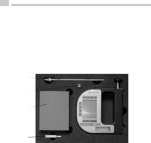
Fig. 5 - 1 Supplied items
1... DMA 35 density meter
2... IrDA USB adapter (optional)
3... Plastic syringes 2 mL
4... Luer adapter 1/4" UNF (for syringe filling)
5... Filling tube (standard 180 mm)
14 |
C96IB001ML-A |

EN
Table 5.1: Supplied parts
Symbol |
Pcs. |
Article Description |
Mat. No. |
|
|
|
|
|
1 |
DMA 35 portable density meter or |
84138 or |
|
|
DMA 35 Tag&Log portable density |
87448 |
|
|
meter or |
or |
|
|
DMA 35 Ex portable density meter or |
87450 or |
|
|
DMA 35 Ex Petrol portable density |
87451 |
|
|
meter |
|
|
|
|
|
|
1 |
Instruction Manual |
|
|
|
English/German |
88155 |
|
|
|
|
|
1 |
Filling tube (standard 180 mm) |
68527 |
|
|
|
|
|
1 |
Luer adapter 1/4" UNF (for syringe |
64792 |
|
|
filling) |
|
|
|
|
|
|
10 |
Plastic syringes 2 mL |
58802 |
|
|
|
|
|
1 |
Allen wrench 2.5 mm DIN 911 |
58263 |
|
|
|
|
C96IB001ML-A |
15 |

EN
Table 5.2: Optional parts
Article Description |
Mat. No. |
|
|
ABS disc tag 30 mm, 5 mm hole R |
92412 |
|
|
ABS disc tag 30 mm, 5 mm hole R/W |
88443 |
|
|
Black laundry tag 30 mm R |
92413 |
|
|
Black laundry tag 30 mm R/W |
88444 |
|
|
White PVC sticker disc tag 30 mm R/W |
88445 |
|
|
White PVC sticker disc tag 30 mm R |
92414 |
|
|
Carrying case for DMA 35 |
88506 |
|
|
Custom function for DMA 35 |
88974 |
|
|
DKD calibration DMA 35 |
88153 |
|
|
Filling tube PTFE, length: 600 mm |
78503 |
|
|
IrDA USB adapter LCS-8141 |
88085 |
|
|
Printer CMP-10-E5 RS232C/IrDA |
87817 |
|
|
Set wristband for DMA 35 |
92416 |
|
|
16 |
C96IB001ML-A |
EN
6 Description of the Instrument
6.1Front View
1
7
6
2
5 |
4 |
3 |
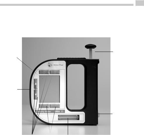
Fig. 6 - 1 Front view of DMA 35
1... Built-in pump
2... Screw plug
3... Measuring cell
4... Softkeys
5... Operating keys
6 |
... RFID interface (only for DMA 35 Tag&Log, DMA 35 Ex and DMA 35 |
|
Ex Petrol) |
7 |
... Graphical, monochrome LC display |
C96IB001ML-A |
17 |
EN
2 |
3 |
1 |
|
|
|
4 |
|
|
|||
|
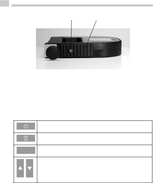
Fig. 6 - 2 Top view of DMA 35
1... Built-in pump
2... Fixing screw of the pump lock
3... Pump lock
4... Infrared interface (IrDA)
Keys at the front side
For switching the instrument on and off.
For deleting measuring data, entries and characters during an entry.
Softkeys for selecting menu items and for navigation. The function of the right softkey can be configured.
Arrow keys for navigation within the menu and for the entry of characters.
TIP For faster up and down navigation, keep the arrow keys pressed.
18 |
C96IB001ML-A |
EN
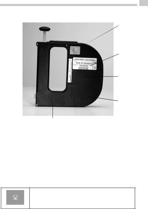
6.2Rear View
 1
1
 2
2
3
4
6 |
5 |
Fig. 6 - 3 Rear view of DMA 35
1... Data storage key
2... Type plate with serial number
3... Registration number and ATEX marking (only for DMA 35 Ex and DMA 35 Ex Petrol)
4... Custom functions (optional)
5... Mark for the correct battery insertion
6... Calibration number (optional)
Key at the rear side
For starting a measurement and storing results in the memory
C96IB001ML-A |
19 |
EN
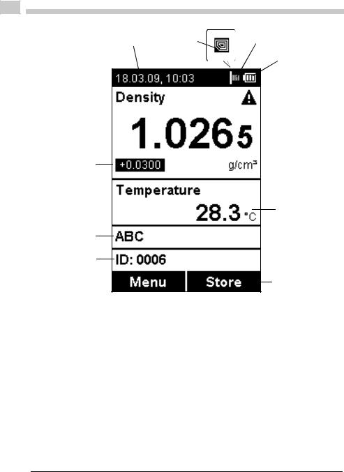
6.3Display
2 |
3b |
|
|
3a |
||||||||||||||
|
||||||||||||||||||
1 |
|
|
|
|
|
|
|
|
|
|
|
4 |
||||||
|
|
|
|
|
|
|
|
|
|
|
||||||||
|
|
|
|
|
|
|
|
|
|
|
||||||||
|
|
|
|
|
|
|
|
|
|
|
|
|
|
|
|
|
5 |
|
|
|
|
|
|
|
|
|
|
|
|
|
|
|
|
||||
12 |
|
|
|
|
|
|
|
|
|
|
|
|
|
|
|
|
|
|
|
|
|
|
|
|
|
|
|
|
|
|
|
|
|
|
|||
|
|
|
|
|
|
|
|
|
|
|
|
|
|
|
|
|||
|
|
|
|
|
|
|
|
|
|
|
|
|
|
|
|
6 |
||
|
|
|
|
|
|
|
|
|
|
|
|
|
|
|||||
|
|
|
|
|
|
|
|
|
|
|
|
|
||||||
11
7
10
9
8
Fig. 6 - 4 Display of DMA 35
1... Information header
2... Date and time
3... Symbol for infrared data transfer (3a) or RFID symbol1 (3b)
4... Symbol for battery charge status
5... Warning sign
6... Measuring value
7... Sample temperature °C/°F
8... Softkey configuration
9... Sample ID
10... Method
11... Custom offset
12... Measuring unit
1 Only for DMA 35 versions with RFID interface
20 |
C96IB001ML-A |
EN
Symbols on the display
The infrared data transfer symbol is shown on the information header when data is imported or exported via the IrDA interface.
The RFID symbol is shown on the information header when it is possible to allocate an RFID tag to a method or sample ID and when an RFID tag is read while the instrument displays the main screen. Furthermore, methods and/or sample IDs with an allocated RFID tag are marked with this symbol when listed.
The battery charge status symbol informs you about the battery charge status of your instrument. For further information on different charge status symbols and their meanings, see Chapter 12.1.
The warning sign indicates that a measured value is outside range specifications. The warning sign is always shown together with an information (press the right softkey) stating the warning type (for details about warning types, see Chapter 14).
TIP You can change between the <Info> softkey which is displayed together with the warning sign and the original softkey configuration by pressing the arrow keys.
C96IB001ML-A |
21 |

EN
7 Operating the DMA 35
7.1Connecting the Filling Tube
•Screw in the filling tube by hand until you feel some resistance against turning. Do not use any tools for screwing in the filling tube.
Fig. 7 - 1 Connecting the filling tube
7.2Attaching the Syringe Adapter
1.Remove the screw plug at the side of the instrument.
2.Screw in the Luer adapter (see Chapter 5) by hand until you feel some resistance against turning. Do not use any tools for screwing in the Luer adapter.
22 |
C96IB001ML-A |

EN
7.3 |
Switching the Instrument On |
|
• |
To switch the instrument on, press the |
key. |
|
After showing the welcome screen, DMA 35 immediately switches to the main |
|
|
screen (measuring mode). Now you can start with the measuring process. |
|
7.4 |
Switching the Instrument Off |
|
•To switch the instrument off, press the  key until "Power Off" is displayed.
If the instrument is in the energy saving mode (see Chapter 8.4), DMA 35 switches automatically off after 3, 5 or 10 minutes inactivity (depending on the setting).
C96IB001ML-A |
23 |

EN
8 Defining the Basic Settings
8.1Language Settings
You can choose between two different menu languages:
1.Press <Menu> and select "Setup > Language".
2.Select the preferred language and press <OK>.
8.2Units
1.Press <Menu> and select "Setup > Units".
2.Select g/cm3 or kg/m3 as the density unit and press <OK>.
3.Select °C or °F as the temperature unit and press <Save>.
8.3Sound Settings
When sound is enabled, DMA 35 beeps when it is switched on and off and when a key is pressed.
When sound is disabled, the instrument only beeps when it is switched on and off.
1.Press <Menu> and select "Setup > Beep".
2.Select the preferred setting (Beep on/off) and press <Save>.
8.4Energy Saving Mode
Enabling the energy saving mode lowers the power consumption of the instrument and thus extends battery life. When the energy saving mode is enabled, the instrument will automatically switch itself off after 3, 5 or 10 minutes of inactivity.
When the energy saving mode is disabled, the instrument will remain switched on until it is turned off using the  key.
key.
1.Press <Menu> and select "Setup > Energy Saving".
2.Select the preferred setting (Off, 3, 5 or 10 minutes) and press <Save>.
24 |
C96IB001ML-A |

EN
8.5Backlight
The LC display and the oscillator are equipped with a backlight. The backlight ensures that even under bad lighting conditions the measuring results and menu options are easily readable. The backlight of the oscillator enables you to observe the filling process.
You can choose between "Auto", "Off" and "On":
Auto |
The backlight automatically turns on when a key is pressed or when |
|
a new sample is filled into the measuring cell. To activate the |
|
backlight without accessing the menu, press an arrow key. The |
|
backlight switches off automatically after 30 seconds. |
|
|
Off |
The backlight is permanently off. |
|
|
On |
The backlight is permanently on. |
|
|
TIP Having the backlight turned on permanently will shorten battery life.
1.Press <Menu> and select "Setup > Backlight".
2.Select the preferred setting (Auto, Off, On) and press <Save>.
8.6Contrast Settings
The display contrast can be freely adjusted to suit your preference.
1.Press <Menu> and select "Setup > Display Contrast".
2.Select the preferred setting (-8 to +8) and press <Save>.
8.7Allocation of the Softkey Function
On the front side of DMA 35 are two softkeys. When the instrument displays the main screen, the left softkey always takes you to the main menu. The right softkey can be allocated with one out of three predefined functions. The allocated function is only available in the main screen.
C96IB001ML-A |
25 |

EN
The functions available are "RFID2", "Store" and "Print".
RFID |
Enables programming and reading of RFID tags for the purpose |
|
|
of quick sample identification. |
|
|
|
|
Store |
Provides the same functionality as the |
key on the back of |
|
||
|
the instrument and starts and stores a measurement. |
|
|
|
|
Enables immediate print-out of the measured value using the |
||
|
IrDA interface. |
|
|
|
|
1.Press <Menu> and select "Setup > Softkey".
2.Select the preferred setting (RFID, Store, Print) and press <Save>.
8.8Password Protection
You can protect your instrument with a password according to your demands. If the password protection is enabled, the password needs to be entered before changing the settings, before performing an adjustment and before selecting a measuring unit.
For performing measurements as well as entering, changing or deleting measuring methods or sample IDs no password entry is required.
You can anytime change the password later on or disable password protection entirely. Keep your password information safe.
To set, change or delete a password
1.Press <Menu> and select "Setup > Set Password".
2.If your instrument is already password protected, enter your current password.
3.Enter your new password using the arrow keys and press <Continue>.
4.If you want to disable the password protection entirely, enter <0000> as the new password and press <Continue>.
5.Enter the password again and press <Save>.
2 Only for DMA 35 versions with RFID interface
26 |
C96IB001ML-A |

EN
8.9Date and Time Settings
During operation the information header always displays the current date and time.
To set date and time
1.Press <Menu> and select "Setup > Date and Time > Set Date and Time".
2.Enter the current day, month and year using the arrow keys and confirm each of your selections by pressing <OK>.
The cursor moves to the next value to be set.
3.Press <Save>.
Now the time settings are displayed on the screen.
4.Repeat the procedure to enter the current time and press <Save>.
To set the date format
1.Press <Menu> and select "Setup > Date and Time > Date Format".
2.Select the preferred date format and press <OK>.
To set the time format
1.Press <Menu> and select "Setup > Date and Time > Time Format".
2.Select the preferred time format and press <OK>.
C96IB001ML-A |
27 |

EN
9 Exchanging Data with a PC
Your DMA 35 features wireless data transfer from and to a PC via the integrated IrDA interface. You need a PC with an infrared interface or a PC with an IrDA USB adapter installed and connected. Contact your Anton Paar representative if you need an IrDA USB adapter for your PC.
9.1 Establishing a Connection to a PC
1. If your PC has no IrDA interface, install the IrDA USB adapter on your PC.
2. Hold the IrDA interface of DMA 35 to the IrDA interface of your PC to establish communication between the two instruments.
3. Continue with Chapter 9.2 or Chapter 9.3.
9.2 Exporting Data to a PC
The following data can be exported from your instrument to a PC:
•Measured data (see Chapter 10.9 for further options how to export measured data)
•Custom functions (custom-specific measuring units)
•Adjustment data (currently valid adjustment)
•Device information
•Sample ID list
•Method list
•System settings (backup copy of instrument)
1.Establish a connection between the DMA 35 and the PC (see Chapter 9.1).
2.Press <Menu> and select "Setup > Import / Export > Send to PC".
3.Select the type of data you want to export.
A dialog window appears on your PC asking if you want to accept the file.
4.Click <Yes>.
The selected data are transferred and filed on the desktop.
28 |
C96IB001ML-A |

EN
9.3Importing data from a PC
The following data can be imported from a PC to your instrument:
•Custom functions
•Sample ID list
•Method list
•Firmware updates
1.Establish a connection between the DMA 35 and the PC (see Chapter 9.1).
2.Press <Menu> and select "Setup > Import / Export > Receive from PC".
3.On the PC, right mouse-click on the file you want to send and select "Send to > A nearby computer".
The selected file is transferred to the instrument.
C96IB001ML-A |
29 |
EN
10 Performing a Measurement
General instructions for measuring
WARNING
Handling samples with temperatures of more than 70 °C bears the danger of heavy burns.
•Make sure you wear protective clothes or ensure alternative protection from burns when handling high temperature samples.
WARNING
DMA 35 is not insulated against high voltages. Measuring samples under high voltage (e.g. in energized battery banks) bears the risk of an electric shock.
•Define appropriate testing procedures and safety measures to protect yourself from any electric shock.
NOTICE Before performing a measurement, make sure that the wetted parts are resistant to the sample (see Chapter 16).
NOTICE Sample containing dissolved CO2 will cause bubbles within the measuring cell with the effect of invalid measurement results. Make sure your sample is degassed carefully.
Degassing a sample can be done by:
•boiling the sample for several minutes,
•stirring the sample for 5 to 15 minutes until no bubbling occurs any more or
•putting the sample for approximately 5 to 10 minutes into an ultrasonic bath.
•Make sure that the measuring cell is filled free from gas bubbles. Possible reasons for gas bubbles in the measuring cell are:
•Gas bubbles in the sample
•Leaky connection of the filling tube, the pump or the screw plug
•Make sure that the measuring cell is fully filled.
•Make sure that the sample temperature does not deviate too strongly from the ambient temperature.
30 |
C96IB001ML-A |
Loading...