


Anthony International
Maintenance and Service Manual
Anthony Model 601B
Outside Mount Door
99-16105-S002

601B, 6001 Outside Mount - Installation Manual
TITLE:
99-16105-S002
Model 601B Outside Mount
Door
REV.
B
Page 2 of 43
Table of Contents
1. Parts Placement...............................................................................................................4
2. Door and Hardware Removal ..........................................................................................8
2.1. Door Removal Procedures ....................................................................................8
2.1.1. Removing the 6000 door assembly top hinge ..........................................8
2.1.2. Removing the 6000 door assembly bottom hinge ..................................10
3. Door and Hardware Installation .....................................................................................11
3.1. Preli
minary Considerations .................................................................................11
3.1.1. Installation and Replacement Procedures .............................................12
3.1.1.1. Removing the Torque Rod.....................................................12
3.1.1.2. Installing the Door Hinge Brackets.........................................13
3.1.1.3. Torquemaster Installation ......................................................14
3.2. Installing the 6000 Door Assembly (1983 to 1995)..............................................14
3.3. Installing the 6001 and the 601B Door Assembly (1995 to Present) ...................17
3.4. Installing the Door Hold-Open Device .................................................................19
3.5. Ordering Replacement Doors..............................................................................20
4. Repair and Replacement Procedures ............................................................................21
4.1. Removing the Door Gasket, Plastic and Handle .................................................21
4.2. Replacing the Door Handle .................................................................................22
4.3. Replacing the Door Plastic Cover .......................................................................23
4.4. Replacing the Door Gasket .................................................................................24
4.5. Cylinder Lock Repair and Replacement ..............................................................24
4.6. Door Bumper Removal and Replacement...........................................................26
4.7. Door Heater W ire Replacement ..........................................................................27
5. Door Glass Installation ...................................................................................................30
5.1. Glass Pack Replacement Procedures.................................................................30
6. Handle Assembly Removal ............................................................................................36
6.1. Preliminary Considerations .................................................................................36
6.2. Handle Assembly Removal Procedure................................................................36
7. Electrical Information .....................................................................................................39
7.1. Model 601B ADM Door Amperages at 120 Volts ................................................39

601B, 6001 Outside Mount - Installation Manual
TITLE
99-16105-S002
Model 601B Outside Mount
Door
REV.
B
Page 3 of 43
8. Dew Point Chart.............................................................................................................40
8.1. Normal Temperature Applications .......................................................................40
8.2. Low Temperature Applications ............................................................................40

601B, 6001 Outside Mount - Installation Manual
TITLE:
99-16105-S002
Model 601B Outside Mount
Door
REV.
B
Page 4 of 43
Preliminary Considerations for Door and Frame Servicing Procedures
SAFETY
Proper safety equipment includes:
•
safety glasses
•
work gloves
•
work shoes.
Confirm that power has been removed from the door. Use extra caution when working with or
around the door glass package. Remove electrical power to the door assemblies prior to
starting work.
TOOLS
Do not use power tools for the following procedures. The tools required for this procedure
include:
•
#2 Phillips-head screwdriver
•
Flat-head screwdriver
TIPS
•
Needle-nose pliers
•
Rubber or plastic mallet
•
7/16” and 1/2” Hand Wrench
•
5/32” Hex Key
•
Wire stripper and cutter
•
Soldering iron
•
Heat Gun
•
Razor Knife
•
Complete replace of wire assemblies is recommended whenever required. Splice
wires only if necessary, using proper materials such as, electrical tape, wire nuts,
flux core solder and heat shrink.
•
Apply liquid soap to rail plastic covers and gaskets upon installation to facilitate
insertion into mounting grooves.
•
Keep doors clean for product efficiency. This can also help reduce energy
consumption and potential health hazards.
•
Whenever binding gasket or plastic parts, use food grade silicone.
•
Whenever replacing fluorescent lamps, always replace lamp covers as well.
•
Always use the correct tool for the job to be performed. This ensures proper
installation and minimizes safety risks.
•
If there is any doubt about the work to be performed, consult with a certified
technician or Anthony representative.
•
Preventative maintenance is recommended to ensure product longevity.

601B, 6001 Outside Mount - Installation Manual
TITLE
99-16105-S002
Model 601B Outside Mount
Door
REV.
B
Page 5 of 43
1. PARTS PLACEMENT
Diagram A: Model 601B Door Assembly
1 Torque Rod Assembly 8 S.J. Cord
2 Gasket with Magnet 9 Access Hole Cover
3 Corner Pieces
4 Door Rail (Hinge side)
5 Door Rail (Handle side)
6 Top & Bottom Rail
7 Hold Open Backing Plate
10 Top & Bottom Rail Cover
11 Side Rail Covers
12 Wedge Spacer
13 Vinyl Glazing
14 Glass Pack Assembly
15 10-28 x 5/8” Screws
16 3/16” x 3/8” x 3/8” Rivets 23 Foam Mounting Tape
17 8-32 x 5/8” Screws
18 #42 Steel Rivets
19 Slimline Handle
20
Hinge Pin
21 Hinge Pin Adapter
22 Sealant
24 3M Hot Melt Sealant
25 Door Handle Rail Insert
26 Hinge Pin Locking Clip Instructions

601B, 6001 Outside Mount - Installation Manual
TITLE:
99-16105-S002
Model 601B Outside Mount
Door
REV.
B
Page 6 of 43
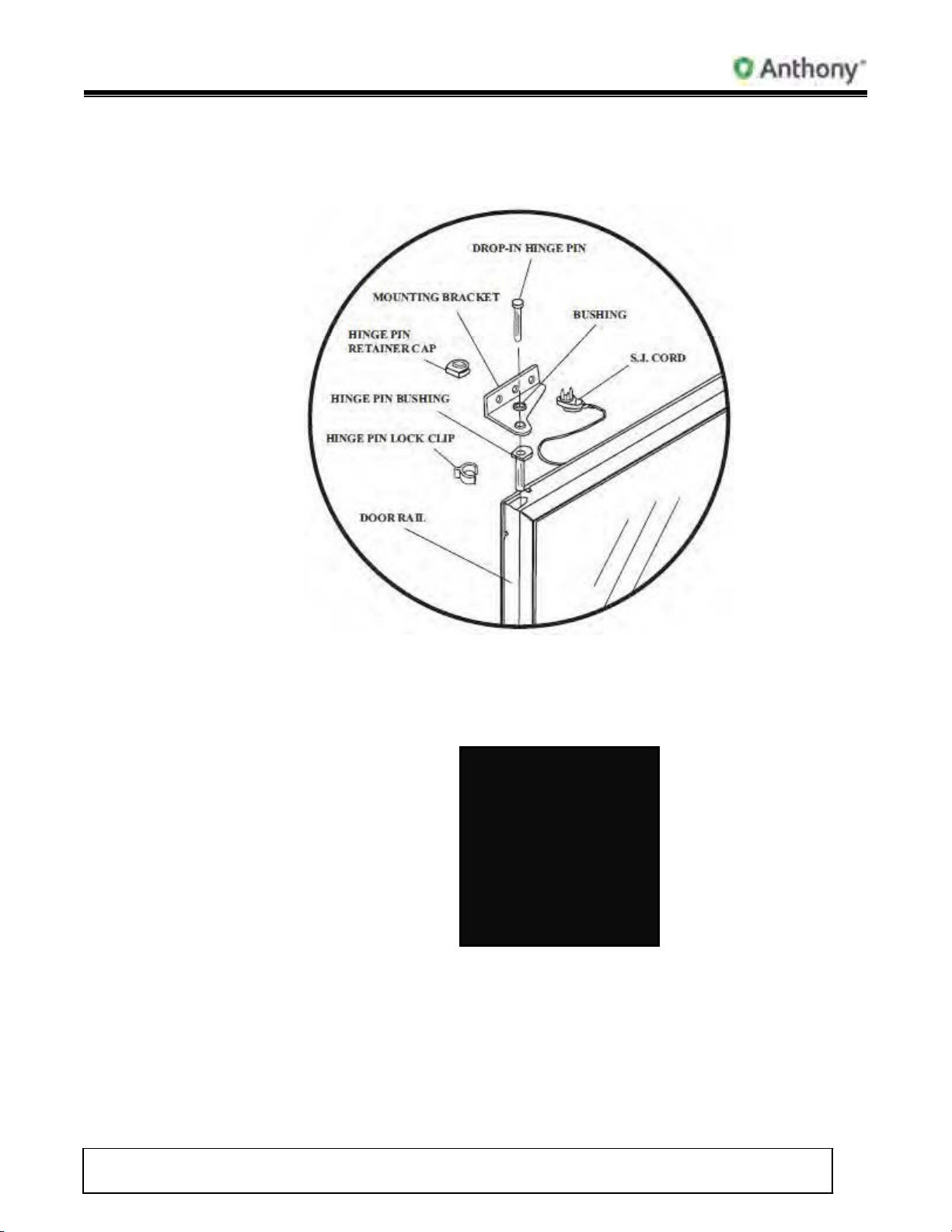
1
Pin Retainer Cap
7
S.J. Cord
13
Hex Torque Rod
2
Bushing
8
Handle
14
Bottom Bracket
3
Drop-In Hinge Pin
9
Heater Wire
15
Torquemaster
6
Hinge Pin Lock Clip
12
Glazing Channel
18
Door Assembly
Diagram B: Model 6000 & 6001 AOM Door Parts Placement
(1983 to 1995)
4 Right Angle Bracket 10 Gasket 16 Hold-Open Stud
5 Hinge Pin Bushing 11 Plastic Cover 17 Hold-Open Arm
601B, 6001 Outside Mount - Installation Manual
TITLE
99-16105-S002
Model 601B Outside Mount
Door
REV.
B
Page 7 of 43
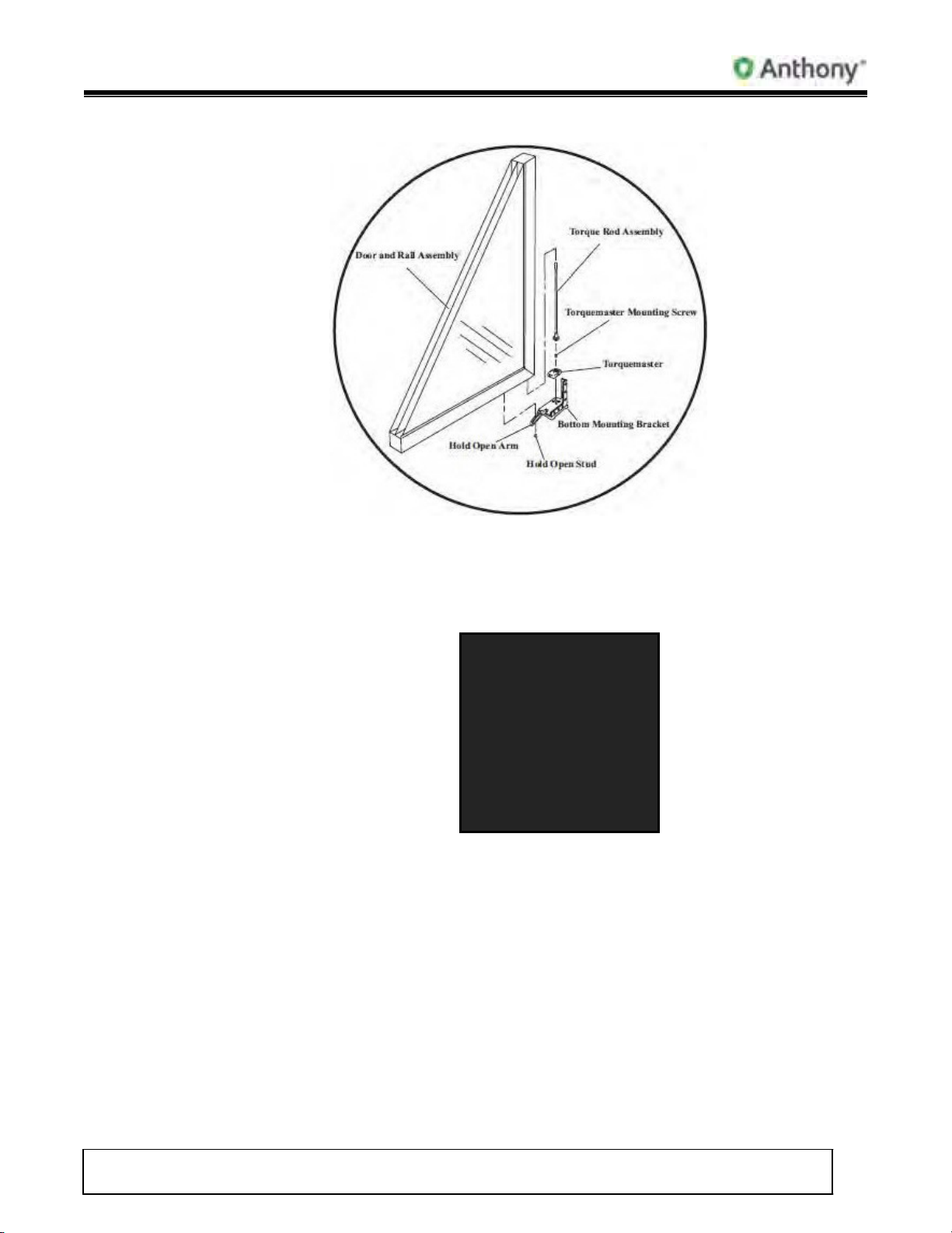
1
Threaded Hinge Pin
5
S.J. Cord
9
Plastic Cover
13
Torquemaster
2
Right Angle Bracket
6
Handle
10
Glazing Channel
14
Hold-Open Stud
3
Hinge Pin Bushing
7
Heater Wire
11
Hex Torque Rod
15
Hold-Open Arm
4
Hinge Pin Lock Clip
8
Gasket
12
Bottom Bracket
16
Door Assembly
Diagram C: Model 6000 & 6001 AOM Door Parts Placement
(1995 to 2005)
601B, 6001 Outside Mount - Installation Manual
TITLE:
99-16105-S002
Model 601B Outside Mount
Door
REV.
B
Page 8 of 43
1
Threaded Hinge Pin
5
S.J. Cord
9
Plastic Cover
13
Torquemaster
2
Right Angle Bracket
6
Handle
10
Glazing Channel
14
Hold-Open Stud
3
Hinge Pin Bushing
7
Heater Wire
11
Hex Torque Rod
15
Hold-Open Arm
Diagram D: Model 601B AOM Door Parts Placement
(April 2005 to Present)
4 Hinge Pin Lock Clip 8 Gasket 12 Bottom Bracket 16 Door Assembly
601B, 6001 Outside Mount - Installation Manual
TITLE
99-16105-S002
Model 601B Outside Mount
Door
REV.
B
Page 9 of 43
2. Door and Hardware Removal
2.1 Door Removal Procedures
2.1.1 Removing the 6000 door assembly top hinge.
1. Access the Torquemaster located at the bottom door hinge.
2. Using a slot or flat-head screwdriver, turn the front torque adjustment
screw clockwise for several turns until tension is removed from the torque
rod.
3. Using a phillips-heads screwdriver, loosen the fastener securing the power
cord plug to the power receptacle.

601B, 6001 Outside Mount - Installation Manual
TITLE:
99-16105-S002
Model 601B Outside Mount
Door
REV.
B
Page 10 of
4. Carefully remove plug by pulling the plug from the power receptacle in the
case frame.
5. Using needle nose pliers, remove the Hinge Pin Lock Clip by gripping the
clip flange and pulling out away from the hinge pin.
6. Remove the hinge pin retainer cap from the hinge pin and the top hinge
mounting bracket.
7. Acquiring assistance, brace the door before proceeding any further.
601B, 6001 Outside Mount - Installation Manual
TITLE
99-16105-S002
Model 601B Outside Mount
Door
REV.
B
Page 11 of 43
2.1.2 Removing the 6000 Door Assembly Bottom Hinge
NOTE: Bracing the door before removing the hinge pin is necessary to
avoid the door assembly from falling, which could cause severe
damage and injury.
1. Remove hold-open door stop from bottom door rail.
NOTE: Acquire additional assistance before proceeding any further with
the door removal.
WARNING: Use extreme caution when lifting and moving the door
assembly to prevent damaging the door. Using safety
gloves when handling the unhinged door is recommended.

601B, 6001 Outside Mount - Installation Manual
TITLE:
99-16105-S002
Model 601B Outside Mount
Door
REV.
B
Page 12 of
2. Lift and remove the hinge pin from the hinge pin socket in the top door rail.
3. Carefully tilt the top of the door away and down from the case frame, no
more than 15 degrees.
4. Carefully lift the door up and out of the Torquemaster socket completely.
5. Once the door has been removed, handle with care when carrying,
storing, returning or discarding.
3. Door and Hardware Installation
3.1 Preliminary Considerations.
SAFETY
Be sure to use the proper safety equipment before beginning work, including the
required safety glasses, gloves and work shoes. Confirm that power has been
removed from the door. ALW AYS exercise extra caution whenever working with
sharp-edged or powered tools. The glass pack is made with tempered glass. Use
caution when working around the glass pack.

601B, 6001 Outside Mount - Installation Manual
TITLE
99-16105-S002
Model 601B Outside Mount
Door
REV.
B
Page 13 of 43
INSTALLATION CONSIDERATIONS
•
Use Anthony approved hinge and bracket support systems for use with the
case body and door rails.
•
Door rails and plastic cover materials must be compatible with the Anthony
magnetic gasket seal.
•
For a proper seal of the magnetic gasket, correct magnetic case material is
required with net dimensions of the frame, or case opening at two (2)
inches, or 5.1 cm, smaller than the door dimensions.
•
Confirm that the case, frame and structure support are adequate prior to
door installation.
3.1.1 Installation and Replacement Procedures
3.1.1.1 Removing the Torque Rod.
1. Carefully place a flathead screwdriver between the door rail and
the washer beneath the torque rod.
2. Dislodge the torque rod from its mount by pushing on the torque
rod or tap it loose using a plastic or rubber mallet. DO NOT use
a steel-headed hammer.
NOTE: Use caution when striking any tool with another tool.
DO NOT use excess force when striking the
screwdriver and potentially damaging either tool.

601B, 6001 Outside Mount - Installation Manual
TITLE:
99-16105-S002
Model 601B Outside Mount
Door
REV.
B
Page 14 of
3. Continue to carefully tap the torque rod, if necessary, until the
torque rod and rod end come loose.
4. Carefully pull the torque rod assembly out.
5. Reverse the process to re-install the torque rod assembly into
the door rail.
•
Insert torque rod into the bottom of the door until it is fully
seated.
•
If required, tap the torque rod assembly into the torque
rod socket, using a plastic or rubber mallet until the
torque rod is fully seated into the receptacle.
3.1.1.2 Installing the Door Hinge Brackets
1. Place the upper hinge bracket onto the door rail.
2. Align the bracket mounting holes with the door mounting holes.
3. Insert mounting screws into mounting holes and twist each
screw in a clockwise direction until the threads catch.
4. Using a phillips head screwdriver, continue turning each screw
clockwise until they are fully tightened.
5. Place the lower hinge bracket onto the door rail
6. Align the bracket mounting holes with the door mounting holes.
7. Insert mounting screws into mounting holes and twist each
screw in a clockwise direction until threads catch.
8. Using a phillips head screwdriver, continue turning each screw
clockwise until all of them are fully tightened.

601B, 6001 Outside Mount - Installation Manual
TITLE
99-16105-S002
Model 601B Outside Mount
Door
REV.
B
Page 15 of 43
3.1.1.3 Torquemaster Installation
1. Place Torquemaster onto bottom door bracket.
2. Align the mounting cut-outs on the bracket with the mounting
flanges located on the bottom of the Torquemaster, and insert
the flanges into the lower bracket cut-outs until fully seated.
3. Insert the mounting screw into the Torquemaster mounting hole
located in center of the torque rod mounting cavity.
4. Using a phillips-head screwdriver, turn the mounting screw in a
clockwise direction until it is tightened, securing the
torquemaster.
3.2 Installing the 6000 Door Assembly (1983 to 1995)

601B, 6001 Outside Mount - Installation Manual
TITLE:
99-16105-S002
Model 601B Outside Mount
Door
REV.
B
Page 16 of
1. Carefully inspect the entire door assembly and verify that the following items
are in order:
•
Door rails are intact, including handle and glass seal.
•
Glass pack is sealed and free of cracks or damage.
•
Torque rod is properly installed and tight.
•
Electrical power cord is intact.
2. Carefully place door onto bottom bracket, inserting the large end of the torque
rod into the cavity in the Torquemaster.
3. Confirm torque rod installation by checking rod end and verifying that it is fully
seated into the Torquemaster.

601B, 6001 Outside Mount - Installation Manual
TITLE
99-16105-S002
Model 601B Outside Mount
Door
REV.
B
Page 17 of 43
4. At the top hinge, insert the hinge pin adapter between the bracket and the top
hinge pin socket of the door.
5. Align the hinge pin adapter with the hinge pin hole of the top mounting bracket.
6. Place the hinge pin bushing onto the hinge pin mounting hole on top of
mounting bracket and align it with the mounting hole.

601B, 6001 Outside Mount - Installation Manual
TITLE:
99-16105-S002
Model 601B Outside Mount
Door
REV.
B
Page 18 of
7. Insert the hinge pin into the hinge pin socket and press it in until it is fully
seated. If necessary, strike the pin with a plastic or rubber mallet to facilitate full
installation.
8. Install the hinge pin retaining cap around the mounting bracket and onto the
hinge pin. Verify that the retaining cap in securely in place.
9. Insert the hinge pin lock clip in between the adapter and the top of the door rail,
around the shaft of the hinge pin. Verify that the hinge pin lock clip is securely
in place.
10. Check the door installation and verify both the stability and door operation.
NOTE: Replacement doors are very heavy. ALW AYS use extra caution
when handling the door assembly, for removal or replacement, to
avoid possible damage and injury.

601B, 6001 Outside Mount - Installation Manual
TITLE
99-16105-S002
Model 601B Outside Mount
Door
REV.
B
Page 19 of 43
3.3 Installing the 6001 and the 601B Door Assembly (1995 to Present)
1. Carefully inspect the entire door assembly and verify that the following items
are in order:
•
Door rails are intact, including handle and glass seal.
•
Glass pack is sealed and free of cracks or damage.
•
Torque rod is properly installed and tight.
•
Electrical power cord is intact.
2. Carefully place door onto bottom bracket, inserting the torque rod-end fitting
into the cavity in the Torquemaster.

601B, 6001 Outside Mount - Installation Manual
TITLE:
99-16105-S002
Model 601B Outside Mount
Door
REV.
B
Page 20 of
3. Confirm torque rod installation by checking rod end and verifying that it is fully
seated into the Torquemaster.
4. Insert the hinge pin into the hinge pin socket of the top door rail and press it in
until it is fully seated.
5. Align the threading on the top of the hinge pin with the threaded hole in the top
mounting bracket, slightly lifting the hinge pin into the hole.
6. Twist the hinge pin in a clockwise direction to catch the threads and continue
twisting until the hinge pin is installed into the top bracket; then tighten using a
1/2 inch, open-end hand wrench.
7. Insert the hinge pin lock clip in-between the adapter and the top of the door rail,
around the shaft of the hinge pin. Verify that the lock clip is securely in place.
8. Check the door installation and verify both the stability and door operation.

601B, 6001 Outside Mount - Installation Manual
TITLE
99-16105-S002
Model 601B Outside Mount
Door
REV.
B
Page 21 of 43
3.4 Installing the Door Hold-Open Device
1. Insert the hold-open stud through the slot in the hold-open arm, located in the
bottom door mounting bracket hold-open lever.
2. Align the end of the stud with the mounting hole in the bottom of the lower door
rail.
3. Turn the stud in a clockwise direction until the threads catch.
4. Using a 7/16 inch open-ended hand wrench, continue turning the stud until it is
secure.
5. Check the completed assembly and confirm that it is fastened correctly and that
it is fully functional.
6. Make adjustments to the fastener, as needed, to regulate the door-stop
operation.

601B, 6001 Outside Mount - Installation Manual
TITLE:
99-16105-S002
Model 601B Outside Mount
Door
REV.
B
Page 22 of
3.5 Ordering Replacement Doors
When ordering replacement doors, call Anthony International customer service at
800.772.0900 and specify to the representative the need to order a replacement
door. Be sure to provide the all of the required specifications (refer to diagram for
the complete door ordering configuration).
•
Measure and specify the width (A) of the door to the nearest1/16”.
•
Measure and specify the height (B) of the door to the nearest1/16”.
•
Furnish the date of the original order or the Anthony invoice number. (the
original manufacturing date will be stamped on the spacer bar, between
panes of glass (C).
•
Specify whether the replacement door will require a heated glass-pack or
not.
•
Which way does the door hinge (left or right) as well as the type of hinge will
need to be specified.
•
The Anthony representative will need to know if the replacement door is for
a cooler or a freezer.
•
The need for door locks and installation hardware must be specified.
•
The correct electrical voltage is required for the order.
•
Are there any custom items with the original order, if so please specify them
as well as the details of those items.
•
Work Order number from Data Tag (if present-D).

601B, 6001 Outside Mount - Installation Manual
TITLE
99-16105-S002
Model 601B Outside Mount
Door
REV.
B
Page 23 of 43
4. Repair and Replacement Procedures
4.1 Removing the Door Gasket, Plastic and Handle
1. Perform the following procedures to remove the handle door rail assembly.
•
Begin removing the door gasket by carefully lifting the corner.
•
Pull the gasket out of the plastic covers.
•
If there are no access holes to the door handle mounting screws in the
plastic cover, remove the plastic cover from the door rail using a slot-head
screwdriver.
•
Insert a 5/32” Hex key or Allen W rench into the door rail openings and into
the screw head securing the door handle.
•
Turn the screw in a counter-clockwise direction to loosen and remove it.
NOTE: In the event that the screw heads are obstructed with adhesive,
refer to product notification 601B (Appendix A) for instructions
detailing the removal of the obstruction.
•
Repeat the preceding steps with the second mounting screw and remove
the handle assembly from the door.

601B, 6001 Outside Mount - Installation Manual
TITLE:
99-16105-S002
Model 601B Outside Mount
Door
REV.
B
Page 24 of
4.2 Replacing the Door Handle
1. Confirm that the replacement handle assembly kit is complete, including all
threaded screws and washers.
2. Place the lock washers over the threaded end of the screws and slide washers
all of the way to the socket head.
3. Carefully insert both replacement screws all of the way into the mounting holes
into the gasket side of the door rail.
4. Insert the 5/32” hex key or Allen W rench into the socket-head of one of the
screws in the upper door mounting hole. Place the handle onto the door rail,
aligning the handle’s upper mounting hole with the end of the screw that is
protruding from the upper mounting hole in the door rail.
5. Turn the screw in a clockwise direction, catching the threads of the screw into
the mounting hole of the handle.
6. Insert the 5/32” hex key into the lower mounting hole and screw head then turn
the lower screw to catch the threads of the lower mounting hole of the door
handle.
7. Continue turning each screw until both are tightened and the handle is fully
seated against the door rail.

601B, 6001 Outside Mount - Installation Manual
TITLE
99-16105-S002
Model 601B Outside Mount
Door
REV.
B
Page 25 of 43
4.3 Replacing the Door Plastic Cover
1. Insert the inner edge of the plastic cover into the inside groove of one of the
door rails and the outer lip of the plastic cover into the outside groove of the
door rail.
2. Push the plastic cover down and outward, away from the center of the door.
3. Slide along the entire length of the plastic cover while firmly applying pressure
against, as well as down along the length of the door rail, inserting both the
outside lip and the inside lip into the grooves simultaneously.
NOTE: Carefully tapping the plastic cover using a plastic or rubber mallet, with
deliberate strokes, outward and away from the glass, may help seat
the lips of the plastic cover into the grooves of the door rails.

601B, 6001 Outside Mount - Installation Manual
TITLE:
99-16105-S002
Model 601B Outside Mount
Door
REV.
B
Page 26 of
4. Check the entire plastic cover and confirm that both the inside and outside lips
are fully inserted into the door rail grooves.
5. Repeat this procedure, aligning each mitered corner, with all remaining plastic
covers until all four plastic covers are properly installed onto door rails.
4.4 Replacing the Door Gasket
1. Carefully place and align gasket onto a plastic cover with the gasket arrow
facing the door rail and cover.
2. Press the gasket arrow into the groove in the center of the plastic cover until
the edges of the gasket arrow catch and the arrow is fully inserted into the
groove of the plastic cover.
3. Press the gasket firmly against the plastic cover and slide along the gasket,
applying full pressure against the gasket to force the gasket arrow into the
remainder of the groove in the plastic cover.
4. Continue sliding along the gasket, pressing very firmly, until the all of the gasket
arrow is inserted into the grooves, around the entire door rail assembly (if
necessary, a plastic or rubber mallet can be used to facilitate the arrow into the
groove by applying a swift stroke onto the gasket- DO NOT damage the
gasket).
5. Confirm that the entire gasket arrow has been inserted into the all four plastic
cover groove.
4.5 Cylinder Lock Repair and Replacement
1. Remove gasket from door rail containing the lock (leave the gasket on the
remaining door rail assembly).
2. Remove plastic cover from the door rail containing the lock assembly.
3. Insert a large phillips-head screwdriver into the lock access in the back of the
door rail.
4. Turn the lock screw counter-clockwise to loosen the screw.
NOTE: Once the lock screw has been removed, the screw washers and lock
latch will come loose. Be certain that these components are secure

601B, 6001 Outside Mount - Installation Manual
TITLE
99-16105-S002
Model 601B Outside Mount
Door
REV.
B
Page 27 of 43
prior to the removal of the lock screw, or they will become lost if
dropped inside of the door rail.
5. Carefully remove the screw, lock washers and lock latch from the back of the
lock assembly.
6. If necessary, replace the latch.
7. Remove the lock assembly out of the lock housing and through the front of the
door rail.
8. Replace lock assembly into housing inside rail.
9. Replace the latch washer, latch, lock washer and screw to the rear of the lock
assembly and assemble in the correct order.
NOTE: Be certain that the latch is correctly seated onto the end of the
cylinder.
10. Turn lock screw clockwise to catch the threads and tighten the screw
completely.
11. Test lock and confirm that it works properly.
12. Replace the plastic cover and gasket (refer to plastic cover and gasket
replacement instructions).

601B, 6001 Outside Mount - Installation Manual
TITLE:
99-16105-S002
Model 601B Outside Mount
Door
REV.
B
Page 28 of
4.6 Door Bumper Removal and Replacement
1. Using a phillips-head screwdriver, loosen and remove both self-threading
screws and washers at each end of the bumper assembly; then remove
bumper.
2. If necessary, remove bumper mounting brackets.
•
Remove plastic covers from the longer, side door rails.
•
Using a razor knife, carefully cut the silicone adhesive.
•
Loosen and remove bracket mountings screws.
•
Carefully remove mounting brackets.
3. Replace door bumper assembly mounting brackets.
•
Completely clean each bracket of silicone adhesive residue.
•
Apply a generous amount of fresh silicone adhesive to the outside of each
mounting bracket.
•
Insert new self-threading 10-32 X 3/8” screws into the bracket mounting
holes and into the door rail mounting holes.
•
Using a phillips-head screwdriver, turn the screws clockwise until all four
screws are tightened and both mounting brackets are securely fastened.
•
Apply silicone adhesive along the seams of each bracket to ensure a
proper seal.
•
Allow for silicone adhesive to cure.
4. Replace the plastic covers to the door rails (refer to plastic cover replacement
procedures).
5. Replace bumper assembly to the door.

601B, 6001 Outside Mount - Installation Manual
TITLE
99-16105-S002
Model 601B Outside Mount
Door
REV.
B
Page 29 of 43
6. Align the mounting holes in the bumper assembly with the mounting holes in
the mounting brackets.
7. Insert new self threading 10-32 X 5/8” screws into the bumper assembly
mounting holes.
8. Using a phillips-head screwdriver, turn the screws clockwise until each screw is
tight and the bumper assembly is securely mounted.
4.7 Door Heater Wire Replacement
1. Remove door gasket (refer to door gasket removal section for gasket removal
procedure).
2. Remove plastic cover from all door rails (refer to plastic cover removal section
for the removal procedure).
3. Remove power cord plug from socket. The power cord wiring assembly is
usually located in one of the top corners of the door (The wiring configuration
differs per model and individual facility requirements).
4. Locate the cord mounting plate (if applicable) and two mounting screws for the
cord and wire harness mounts, on the outside of the adjacent door rail.
5. Using a phillips-head screwdriver, loosen and remove each screw.
6. Carefully pull out and remove strain relief harness as well as the loop terminal
for the ground (green) wire.

601B, 6001 Outside Mount - Installation Manual
TITLE:
99-16105-S002
Model 601B Outside Mount
Door
REV.
B
Page 30 of 43
7. Locate the heater wire in the grooves of all four door rails. The heater wire is
usually shielded with a fiberglass weave or sleeve.
8. Locate and remove the wire terminals from the door rails
NOTE: Two terminals adjoin the ends of the heater wire with the hot and
neutral wires from the power cord. Two different methods can be used
to disconnect the heater wire from the power cord.
9. Open the wire terminals using a flat-head screwdriver and remove the
terminated heater wire ends.
10. Pull the heater wire out from door rails and remove it.
11. Install the terminated wire ends from the replacement heater wire, then close
the wire terminals.
NOTE: If the replacement heater wire does not have terminated ends, then
splice the wires together.

601B, 6001 Outside Mount - Installation Manual
TITLE
99-16105-S002
Model 601B Outside Mount
Door
REV.
B
Page 31 of 43
1. Cut the (black and white) power wires after the terminals.
2. Strip at least 1/2” of insulation from each wire, exposing the end of the each cut
wire.
3. Strip a minimum of 1/2” of shielding from each end of the heater wire.
4. Insert one two inch heat-shrink tube (not supplied) over each end of heater
wire.
5. Slide each tube down, away from the wire ends.
6. Join the exposed end of each stripped power wire, from the power cord, with
each end of the stripped heater wire.
7. Twist the wire ends together and solder the adjoined wire ends using a
soldering iron and solder.
8. Slide each heat-shrink tube back up the heater wire and over the soldered
wires joints.
9. Using a heat gun, apply a steady flow of heated air onto each shrink tube and
soldered wire joints, to shrink the tubing and insulate the joints.
10. Insert the entire replacement heater wire into the groove inside the door rails
and arrange the wire assembly to the same configuration that it had prior to
disassembly.
11. Carefully re-install the wire assembly into the door rail and the power cord into
strain relief. Be certain to match the original wire installation configuration as
in 1.
12. Mount power cord and strain relief to the door rail using the mounting screws
with new lock nuts.
13. Replace plastic covers and gasket to the door.

601B, 6001 Outside Mount - Installation Manual
TITLE:
99-16105-S002
Model 601B Outside Mount
Door
REV.
B
Page 32 of 43
5. Door Glass Installation
5.1 Glass Pack Replacement Procedures
WARNING: Use extreme caution when working with a razor knife or
handling the glass-pack. Using safety gloves for this procedure
is recommended*. * Referential pictures shown without gloves
for clarity.
1. Carefully remove the door assembly from the hinge mounts.
2. Carefully place the door assembly on a flat, clean and elevated surface or
table.
3. Remove the door gasket (refer to the gasket removal section for removal
procedures).
4. Remove the plastic covers from the door rails (refer to the plastic cover removal
section for removal procedures).
5. Remove the screw fasteners securing the power cord to the door rail.
6. Carefully pull power cord out from the door rail and locate the glass-pack
heater wires.
7. Open each terminal housing, exposing the wire connections.
8. Remove the terminated wires from the terminals.
NOTE: The terminated wire ends of the glass pack wire may not be accessible
or removed. If so skip steps 7 and 8 and proceed to step nine.
9. Carefully cut the glass-pack wires at 1/2” inch from the glass pack assembly.
10. Using a sharp razor knife, carefully insert the knife blade in-between the
glass-pack edge and the door rail.

601B, 6001 Outside Mount - Installation Manual
TITLE
99-16105-S002
Model 601B Outside Mount
Door
REV.
B
Page 33 of 43
11. Cut into the adhesive adjoining the glass pack to the door rail and slice along
the seam between the glass-pack edge and the rail.
12. Continue slicing the glass-pack away from all four door rails.
13. Confirm that the adhesive has been cut completely through as well as all
around the glass-pack.
14. Place a piece of thick foam block underneath the glass-pack at each end of
the door assembly.
15. Press down firmly on each corner of the door rail frame assembly to initiate
the separation of the glass-pack from the door rail frame assembly.

601B, 6001 Outside Mount - Installation Manual
TITLE:
99-16105-S002
Model 601B Outside Mount
Door
REV.
B
Page 34 of 43
16. Once all four corners of the glass-pack have been loosened, go to one end of
the door assembly and place one hand on each corner of the door rail frame
assembly.
17. Press down firmly on both corners of the door rail frame assembly, forcing it
down and separating the frame assembly from one end of the glass pack.
18. Go to the other end of the door assembly and repeat steps 16 and 17 to
separate the other end of the glass-pack from the door rail assembly.
19. If necessary, stack two foam blocks atop one-another and work the door rail
frame downward to facilitate a complete separation of the glass-pack from the
door rail frame.
20. Carefully lift and remove the glass pack from the door rail assembly.
21. Remove foam blocks from the tabletop.
22. Install foam mounting tape along the interior of the frame assembly inside
each rail.
23. Apply a thin strip of silicone adhesive to the interior of the door rail frame,
along-side the foam tape.

601B, 6001 Outside Mount - Installation Manual
TITLE
99-16105-S002
Model 601B Outside Mount
Door
REV.
B
Page 35 of 43
24. Using extreme care, check and confirm that glass-pack heater wires are
aligned with the power cord assembly in the door rail frame assembly. Be
certain that the heater wires are away from the insertion point to avoid
entangling the wires in the adhesive during installation.
25. Insert one side of the replacement glass-pack into the corresponding side of
the frame assembly.
26. Gently insert the remaining side of the glass-pack into the inside of the rail
frame assembly until the glass pack incompletely inserted into the rail frame.
If necessary, use a plastic or rubber mallet and gently tap the edges of the
glass-pack into the rail frame assembly.
27. Replace any loosened spacers and confirm that all four sides of the glass-
pack are fully inserted into the rail assembly and evenly distributed within the
frame.

601B, 6001 Outside Mount - Installation Manual
TITLE:
99-16105-S002
Model 601B Outside Mount
Door
REV.
B
Page 36 of 43
28. If glass-pack wires are terminated, insert the terminated wire ends into the
terminals. If the wire ends are stripped, then strip the cut wires from the
power cord and insert a two inch heat shrink tube over each stripped wire and
slide the tubes away from the stripped wire ends.
29. Join the stripped wire ends from the power cord to the stripped heater wire
ends and lightly twist.
30. Using a soldering iron or gun, solder the wire ends together.
31. Slide the heat shrink tubing over the solder joints of the adjoined wire ends
and, using a heat gun, apply a steady flow of heated air onto each shrink tube
to insulate the soldered wire joints.
32. Inject additional silicone adhesive into the seams between the glass-pack
edges and the door rails.
33. Allow the silicone adhesive to cure.
34. Replace the plastic covers to the door rails (refer to plastic cover replacement
procedures).
35. Replace the gasket to the door assembly (refer to gasket replacement
procedures).
36. Install door assembly to the hinge mounts (refer to door mounting
procedures).
37. Plug power cord into socket to restore power to the re-installed door
assembly.

TilLE
99-16105-5002
Modei6018
Outside Mount
Door
REV.
B
Page 37 of 43
O
Anthony
-
I
II

601B, 6001 Outside Mount - Installation Manual
TITLE:
99-16105-S002
Model 601B Outside Mount
Door
REV.
B
Page 38 of 43
6. Handle Assembly Removal
When accessing the internally mounted door fasteners, interference with the fastener’s socket
heads may be encountered. When attempting to loosen or remove the fasteners, located
inside the door rail, the obstruction should be circumvented or removed from the path of
access.
Perform the following steps to remove the door handle mounting fasteners:
6.1 Preliminary Considerations
1. The tools and materials required to perform this procedure are:
•
Power Drill
•
5/16” Drill Bit
•
5/32” Hex Key or Allen W rench
•
Soapy water or mild lubricant
•
Flathead Screwdriver
•
Plastic or Rubber Mallet
2. Safety practices must be observed.
Always exercise caution when working with both sharp edged and
powered tools.
6.2 Handle Assembly Removal Procedure
1. Remove Gasket:
a. Starting at one corner of the door, carefully lift the corner of the magnetic
gasket.
b. Gently pull up the gasket along the rail and plastic cover.
c. Pull out gasket completely and set gasket aside.
Be sure to handle the gasket carefully to prevent damaging it.
2. If the plastic is not pre-drilled with access holes, remove plastic rail cover on the
handle side of the door only.
a. Insert flathead screwdriver in between plastic cover, corner miter and
carefully pry it upwards.

601B, 6001 Outside Mount - Installation Manual
TITLE
99-16105-S002
Model 601B Outside Mount
Door
REV.
B
Page 39 of 43
b. Lift and remove plastic cover (once again- on door rail of handle side only).
3. Clear obstructive matter from the fastener heads.
Perform the following tasks with extreme caution to avoid damaging the
fastener socket-head, as well as the door glass.
a. Using a power drill with 5/16” drill bit, carefully insert the bit into the access
hole of the door rail.
b. Confirm that the drill aim is perpendicular to the rail and door.
c. Gently apply power to the drill, spinning the bit at a low speed, while
applying pressure to the obstruction, until the obstruction is cleared from the
socket-head.
Drill with
5/16” Bit
Door
Rail
Door
Glass
Door Handle
(Covered)
d. The obstruction is composed of a reasonably soft material and should clear
away relatively easy. DO NOT drill into the socket head.
NOTE: In the event that adhesive has settled inside the socket-head, use a
3/16” drill bit to carefully route the adhesive out of the socket head.
DO NOT strip the hex pattern within the socket head.
4. Remove and replace the handle fasteners from the rail.
a. Once the obstructing matter has been cleared, insert a 5/32” into the socket
head of the handle fastener, and twist it counter-clockwise to loosen the
fastener and remove it.

601B, 6001 Outside Mount - Installation Manual
TITLE:
99-16105-S002
Model 601B Outside Mount
Door
REV.
B
Page 40 of 43
b. Once the fasteners have been removed, replace with NEW socket-head
fasteners. Using the same fasteners to secure the door handle is NOT
recommended.
5. Reassemble the door rail gasket.
a. Replace plastic cover to the door rail.
b. Insert the inside edge of the plastic cover into the inside groove of the rail.
c. Push the plastic cover outward, away from the center of the door, in order to
Outside Lip &
insert the outer lip into the outside groove of the rail.
Gasket
Groove
Inside Lip &
Groove
Door
Rail
Gasket Arrow
& Groove
Door
Glass
d. Replace the gasket to the plastic cover.
e. Insert the gasket arrow into the groove in the center of the plastic cover until
the edges of the arrow catch and are fully inserted into the groove.
f. Press the gasket firmly against the plastic cover and (pressing hard) slide
along the gasket, inserting the remainder of the gasket arrow into the plastic
cover groove.
g. Using the blunt side of a plastic or rubber mallet, strike the gasket onto the
cover and rail to facilitate the gasket arrow into the groove of the plastic
cover.
NOTE: If the gasket arrow is exhibiting difficulty when being reinstalled into
the plastic cover groove, apply soapy water or a mild silicone based
lubricant to the gasket in order to assist in inserting the gasket
arrow into the groove of the plastic cover.

601B, 6001 Outside Mount - Installation Manual
TITLE
99-16105-S002
Model 601B Outside Mount
Door
REV.
B
Page 41 of 43
7. Electrical Information
7.1 Model 601B ADM Door Amperages @ 120 Volts
NORM
•
DOOR SIZE
2 PANE – NHG*
•
3 PANE – NHG*
•
2 PANE – NHG* REFLECTIVE
AL TEMP
NORM
AL TEMP
•
2 PANE – HEATED GLASS
•
3 PANE – HEATED GLASS
•
2 PANE – HEATED GLASS REFLECTIVE
23-3/16 X 34-1/16
23-3/16 X 62-13/16
29-7/8 X 34-1/16
29-7/8 X 62-13/16
29-7/8 X 34-1/16
29-7/8 X 71-1/16
*NHG = Non Heated Glass
STYLE: Normal temperature doors with heaters and 2-pane glass N.H.G.*
0.08
0.12
0.09
0.11
0.13
0.14
0.42
0.73
0.52
0.74
0.93
1.01
APPLICATION: Case temperature 38o F; in-store ambient temp. at 75o F and 63% relative humidity.
STYLE: Normal temperature doors with heaters and 2-pane glass heated glass (5.75 W/SQ. FT.)
APPLICATION: Case temperature 31
o
F; in-store ambient temp. at 75o F and 84% relative humidity.
STYLE: Normal temperature doors with heaters and 3-pane N.H.G.* or 2-pane Reflective heated glass.
APPLICATION: Case temperature 33
STYLE: Low temperature doo
rs with heaters and 3-pane glass heated glass (5.75 W/SQ. FT.)
APPLICATION: Case temperature -10
o
F; in-store ambient temp. at 75o F and 66% relative humidity.
o
F; in-store ambient temp. at 75o F and 74% relative humidity.
NOTES:
1. Although the amperages are calculated at 120 volts, all doors are designed to operate
without sweating, when used within application parameters, with a voltage range of +/-
10%.
2. Design parameters do not make allowances for factors, such as air leaks or unusual air
flow patterns within cases; therefore some sweating may be encountered when upper
limits of temperature or humidity occur.

601B, 6001 Outside Mount - Installation Manual
TITLE:
99-16105-S002
Model 601B Outside Mount
Door
REV.
B
Page 42 of 43
CASE TEMPERATURE (F)
40
35
30
25
20
70
69
65
61
58
55
75
66
62
59
55
52
80
63
59
56
53
50
85
60
57
54
51
48
90
57
55
52
49
47
70
74
71
68
65
62
75
71
68
65
63
60
80
69
66
63
61
58
85
66
64
61
59
57
90
64
62
60
57
55
70
77
74
71
68
65
75
75
72
69
66
63
80
72
70
67
64
61
85
70
67
65
62
59
90
68
65
63
60
58
70
98
94
89
84
80
75
93
89
84
80
76
80
89
85
80
76
73
85
85
81
77
73
70
90
81
77
74
70
67
% REL HUMIDITY @ WHICH CONDENSATION FORMS ON GLASS
CASE TEMPERATURE (F)
+5 0 -5
-10
-15
-20
-25
THREE PANE
70
84
81
79
76
74
72
70
75
81
79
76
74
72
70
68
80
79
77
74
72
70
68
66
86
77
75
72
70
68
67
65
90
75
73
71
69
67
65
63
% REL HUMIDITY @ WHICH CONDENSATION FORMS ON GLASS
8. Dew Point Chart
8.1 Normal Temperature Applications
GLASS TYPE ROOM TEMP (F)
TWO PANE
NHG
THREE
PANE NHG
TWO PANE
REFLECTIVE
NHG
THREE PANE
REFLECTIVE
NHG
8.2 Low Temperature Applications
GLASS TYPE ROOM TEMP (F)
HEATED
REFLECTIVE
GLASS
CALCULATIONS DO NOT PROVIDE ALLOWANCE FOR AIR LEAKS OR UNUSUAL AIR FLOW
PATTERNS WITHIN CASES. THEY ARE INTENDED TO BE USED AS A GUIDELINE ONLY.

601B, 6001 Outside Mount - Installation Manual
TITLE
99-16105-S002
Model 601B Outside Mount
Door
REV.
B
Page 43 of 43
COMPANY POLICIES, TERMS OF SALE, AND WARRANTY
The following terms and conditions shall apply to all transactions and agreements
between Anthony, Inc. (“Anthony”) and the other party to such transaction or
agreement (“Buyer”) with respect to the purchase of any goods from Anthony and/or
the extension of credit by Anthony to Buyer for such purchase.
1. PRICE. Prices shown on the face of the sales invoice are F.O.B. the place of
shipment as designated by Anthony, packaged for shipment and subject to change
without notice.
2. TE
RMS OF CREDIT. All credit terms are net 30 days from date of invoice. Any
deductions from the net invoice amount must be approved by a
Anthony authorized to make such changes. If credit is extended to Buyer, Anthony
reserves the right to revoke such credit if Buyer fails to make timely payment for any
goods delivered. Anthony reserves the right to require payment or other assurances
which it deems necessary prior to the shipment of any goods, if, in Anthon
exercised in Anthony’s subjective, good faith judgment, the Buyer’s financial condition
has deteriorated or the risk of non-payment has otherwise increased. Credit is subject
to approval upon receipt of completed credit application. Any goods shipped prior to
credit approval shall be shipped C.O.D., “Cashiers Check”, or pre-payment. A $25.00
charge will be applied for each returned check. Goods may not be returned for credit
unless prior
authorization
A 1 ½ % per month charge will be assessed on past due amounts.
3. S
HIPMENT OF GOODS / RETURN OF GOODS. Every effort will be made to ship
the goods on the scheduled shipment date and to maintain production schedules
consistent therewith provided however, Anthony shall not be liable for any claims or
consequential
If Buyer refuses shipment of any standard catalog products under an acknowledged
order and those products are consistent with that order and are not deliver
ged or defective, then Buyer will be responsible for (i) return shipment of the
dama
products to Anthony in original shipping containers; (ii) return freight to Anthony
prepaid by Buyer; and (iii) a restocking charge to be determined by Anthony of not
less than twenty-five percent (25%) of the sales price. Buyer assumes the risk of any
return shipment damage or loss, the cost of which will be assessed by Anthony and
added to the restocking charge
may
be returned to Anthony for credit unless those products are not consistent with an
acknowledged
right to cure the defect at the ship-to location. Costs for special packaging and/or
handling requested by Buyer will be billed to Buyer. Shipping terms are specified
face of Anthony’s quotation and/or price list, as applicable. Unless otherwise specified
by Buyer in writing, Anthony shall select the metho
materials to the specified delivery address of Buyer. In the event of any general freight
increase or any governmental ruling or regulation that results in increased freight costs,
Anthony may, without any advance notice, invoice Buyer for such additional costs.
Acceptance and rejections of glass sheets, assembled sealed glass units, and finished
doors shall be in accordance with the defect criteria
ASTM C1036-06
4. RISK OF LOSS. Subject to security interests retained by Anthony until payment for
the goods is received in full, the title to such goods and risk of loss or damages thereto
pass to Buyer upon completion of loading of goods on carrier at Anthony’s factory.
Buyer will unload shipments promptly and Buyer will be liable for any additional charges
such as demurrage, storage, and labor incurred by its failure to do so. Any claims by
Buyer for damages to the
WARRANTIES.
5.
warranted to: (i) be free from defects in materials and
accordance
period of 12 months from the date and place of shipment, provided that the installation
and
maintenance
Anthony’s designated
necessary parts and labor at its cost to fulfill said W arranty. All parts will be shipped
standard ground freight. The extent of Anthony’s liability under the W arranty is limited
to the repair or replacement, at Anthony’s option, of any
without charge, at Anthony’s Sylmar
ears from the shipment date, Anthony will replace sealed glass units that are part
10 y
of an original
results.
Anthony-manufactured
and twelve (12) month labor warranty. The anti-fog coating is only warranted for a
period of twelve (12) months from date of shipment. Anthony reserves the right to
change its warranty provisions at its sole discr
notification of such change.
No Warra
nty for
A
“Non-Standard Product”
Anthony product that has been previously designed and manufactured by Anthony in
accordance
any standard Anthony product that has been specially designed or modified to meet a
particular Buyer
part, accessory, equipment, fixture, component or material, or that has been
as
sembled,
manufactured,
different from Anthony’s standard
disclaims and make no warranties, express or implied, as to the condition, design,
utility, quality,
Product, including, withou
product for a particular purpose or intended use, whether or not such product has
been designated by Anthony as a
and an authorization number have been granted by Anthony.
damages arising from the failure to meet any scheduled shipping dates.
ustom products or custom sizes of catalog items
. No c
order or they are defective. If they are defective, Anthony reserves the
Standards,
level Q3.
oods incurred during shipping shall be made to the carrier.
g
The products which Anthony manufacture and offer for sale are
with applicable refrigeration standards as of the date of
of such products have been performed strictly in
specifications
Anthony-manufactured
Non-Standard
with its standard
specification,
adequacy,
(the “W arranty”). Anthony shall provide all
manufacturing
door if the seal breaks and internal condensation
LED lighting have a five (5) year component warranty
etion at any time with or without prior
Products.
is any product that is different in any manner from any
specifications. A Non-Standard
or that contains any additional or substituted product,
produced, or installed by any method or process, which is
specifications
or capacity with respect to any standard or Non-Standard
t limitation, any warranty of
for such product. Anthony expressly
Non-Standard
Product.
representative
d of shipment and direct shipment of
th in Industry Specification
set for
workmanship;
non-conforming
plant. Additionally, for a period of
Product also includes
merchantability
of
y’s opinion,
ed
and (ii) perform in
manufacture
accordance
with
products
or fitness of such
on
for a
the
All
Non-Standard
standard Anthony products, and all services relating to such products, are sold to and
accepted by Buyer “as is” and “with all faults”. W ithout limiting any other provision of
this purchase order, Anthony shall have no liability to Buyer for any claim, loss,
damage,
Product and/or its use or operation, or any other equipmen
caused by or alleged to be caused by any such product or its use or operation, whether
directly, indirectly, incidentally or
deficiency or defect therein.
The foregoing exclusion of warranty cannot be modified or waived except as
expressly set forth in a writing signed by an officer of Anthony authorized to make
such modification or waiver.
THE ABOVE
EXPRESSED
MERCHANTABILITY
SHALL NOT BE
DAMAGES
PROPERTY.
6.
ACCEPTANCE
must be inspected for damage, loss or shortage prior to acceptance from the carrier. If
damage or shortage exists with respect to any shipment and it is not concealed,
Buyer shall secure a notation of such damage or shortage from the delivering agent
on the freight bill or delivery receipt. If damage is
Anthony within five (5) days of its delivery and hold the
Any claims for visible loss or damage should be filed by Buyer with Anthony in writing
immediately
do not
warr
warranty.
7. CLAIMS
opportunity to inspect the goods. All claims not made in the time period and manner
specified above shall be deemed waived. All actions, claims or defenses by Buyer
shall be deemed waived unless commenced or asserted within six (6) months of
receipt of the goods. No claims for visible, external damage or shortage will be
allowed unless they are
rec
eipt noting such loss or damage signed by a
forwarded to the Anthony Vice President, Marketing & Sales within 30 days of the
invoice date.
8.
CANCELLATION.
Anthony consents in writing to such cancellation.
terms
Buyer will be liable for all cost incurred on the order through the
9. CHANGES BY ANTHONY. Anthony reserves the right to change design, colors
and
10.
petition in
remedies, may repossess any goods which were previously delivered and for which
payment has not been received, and may refuse to make further shipment of goods.
Buyer agrees to pay Anthony’s attorneys’ fees, costs and expenses incurred as a
result of Buyers default or failure to pay, including but not limited to an
repossession
11. E
the entire agreement between Anthony and Buyer with respect to the sale and
purchase of the goods and any extension of credit. If Anthony and Buyer agree to
amend or modify any terms and conditions specified herein, such amendment or
modification must be expressly stated on the face of the sales invoice or by a written
agreement duly executed by an officer of Anthony and the Buyer. The terms spe
herein shall control in the event of any variance between these terms and any terms
contained in Buyer’s purchase orders.
12.
Buyer and all other claims that arise between the parties, whether sounding in
contract or tort, shall be governed by, construed and enforced in accordance with the
laws of the State of California. By entering into this purchase order and any other
agreement with Anthony, Buyer consents to the jurisdiction of the courts of the State
of California to determine all claims between the part
claims are contract claims, tort claims, patent claims, trademark claims or copyright
claims. Venue of any lawsuit (State or Federal) against Anthony must be filed in Los
Angeles County, California. Service of process on Buyer may be made by registered
mail addressed to the Buyer.
.
13
shall be deemed invalid or
construed as though such provision does not appear herein and shall be otherwise fully
enforceable.
14. HEADINGS. The section headings contained herein have been inserted for
convenient
construction
Products, whether sold separately, or incorporated and/or attached to
consequential
conform
anty and Buyer shall be limited to those remedies available for breach of
indemnifying
specifications
DEFAULT.
NTIRE AGREEMENT AND
GOVERNING
SEVERABILITY.
damages or expense associated with any Non-Standard
consequentially,
WARRANTY
IS GIVEN IN LIEU OF ALL OTHER WARRANTIES,
OR IMPLIED, INCLUDING ANY IMPLIED
OR FITNESS FOR A
RESPONSIBLE
INCLUDING BUT NOT LIMITED TO INJURY TO PERSONS OR
OF
upon receipt of the materials. All claims of Buyer that materials delivered
to the accepted order shall be handled as claims for breach of
BY BUYER. Anthony shall thereupon be afforded a reasonable
Anthony against any loss resulting from such action. At minimum,
of any goods without notice to Buyer.
If Buyer defaults or fails to pay on the purchase of any goods or if a
bankruptcy
expenses
LAW. This purchase order, any agreements between Anthony and
reference and shall not be considered in any questions of
of any agreements between Anthony and Buyer.
FOR INCIDENTAL OR CONSEQUENTIAL
PRODUCTS
BY
BUYER/CLAIMS:
accompanied
by an inspection report or signed delivery
Orders may not be canceled after receipt by Anthony unless
is filed by or against Buyer, Anthony, in addition to other
AMENDMENT.
If any provision of the terms and conditions specified herein
unenforceable,
the remaining terms and conditions shall be
t or property of Buyer
or by any inadequacy thereof or
WARRANTIES
PARTICULAR
PURPOSE. ANTHONY
Upon delivery, shipments
concealed,
Buyer must notify
merchandise
for its inspection.
representative
of the carrier and
Cancellation
will be granted only on
cancellation
y collection or
The terms specified herein constitute
egardless of whether said
ies, r
interpretation
OF
date.
cified
or
Anthony products are covered by one or more of the following United States Patents: RE035392, 5301092, 5720540, 5879070, 5895111, 5910083, 5902034, 5959816, 6010227, 6298615,
6302036, 6302557, 6389993, 6343405, 5116274, 5244273, 5255473, 5333355, 5471372, 5645330, 6632100, 6637093, 6638088, 6773130, 6641419, 6490983, 6606832, 6606833,
5884361, D600529, 7603882, 7273299, 7674019, D404935, D395968, D612517, 5622414, 7731395 ,8250873 B2.
Anthony products are covered by one or more of the following Foreign Patents: Canada: 2233401,
For
eign Patents Pending.
Mexico:185899,
186644, 202491, 238593, 227313, 236090. Other United States and
99-18396-W001_E (01/02/2014)
 Loading...