

Model 101 & 2100
(Including Pass-Thru Door Models 103, 105,
107, 2125, 2127, 2130)
Service & Installation
November, 2012
99-13312-S001

Model 101/2100 Doors Service & Installation
TITLE:
99-13312-S001 Model 101/2100 Doors Service &
Installation
REV.
B
Page 2 of 95
Contents:
1. Models 101 & 2100 Door & Frame – Reversible Parts Placement (Start 10/89) ...................6
2. Models 101 & 2100 Reversible Door Parts Placement (1989 to 1991) .................................7
3. Models 101 & 2100 Standard (Before 7/94) Frame Net Opening Widths..............................8
3.1.1. 24” Door (Catalog Size) 23-3/16” Actual Door Width ............................................. 8
3.1.2. 26” Door (Catalog Size) 26-3/8” Actual Door Width ............................................... 8
3.1.3. 30” Door (Catalog Size) 29-7/8” Actual Door Width ............................................... 8
4. Models 101 & 2100 Standard Frame Net Opening Heights ..................................................9
5. Models 101 & 2100 Frame Installation ..................................................................................9
6. Frame Divider Board Installation (Prior to 1993) .................................................................10
7. Reversible/Cordless Door & Hold-Open Installation............................................................11
8. Reversing Frame Hardware ................................................................................................12
9. Door Reversing Instructions Models 101 & 2100 (1989-1991)............................................13
10. Door Reversing Instructions (1991 to Present) ...................................................................16
11. Models 103, 105, 107, 2125, 2127 & 2130 Pass-Thru Installation ......................................17
12. Frame Sill Plastic protector Installation Models 101 & 2100................................................19
13. Contact Plate and Contact Plate Retainer Replacement.....................................................20
14. Ordering Replacement Doors..............................................................................................21
15. Torquemaster Replacement ................................................................................................22
16. Door Gasket Replacement ..................................................................................................22
17. Door Plastic (Cover) Replacement ......................................................................................23
18. Door Cut-Away & Handle Replacement ..............................................................................23
19. Side Access Plate Replacement (1989 to 1991) .................................................................24
20. Side Access Plate Replacement (1991 to Present).............................................................24
21. Door Female Plug Replacement (1989 to 1991) .................................................................25
22. Frame Female Plug and/or Socket Replacement (1991 to Present) ...................................25
23. Door Heater Replacement (1989 to 1991) Model 101 Only ................................................26
24. Door Heater Replacement (1991 to Present) Model 101 Only ............................................26
25. Hinge Pin Replacement (1989 to 1991) ..............................................................................27
26. Hinge Pin Replacement (1991 to Present) ..........................................................................27

Model 101/2100 Doors Service & Installation
TITLE:
99-13312-S001 Model 101/2100 Doors Service &
Installation
REV.
B
Page 3 of 95
27. Wiring Instructions, Heated & Non-Heated Glass (1991 to Present) ...................................27
28. Torque Rod Replacement (1987 to 1991) ...........................................................................28
29. Torque Rod Replacement (1991 to Present).......................................................................28
30. Front Bumper Bar Field Installation .....................................................................................28
31. Model 101 Door Cylinder Lock Replacement or Repair ......................................................29
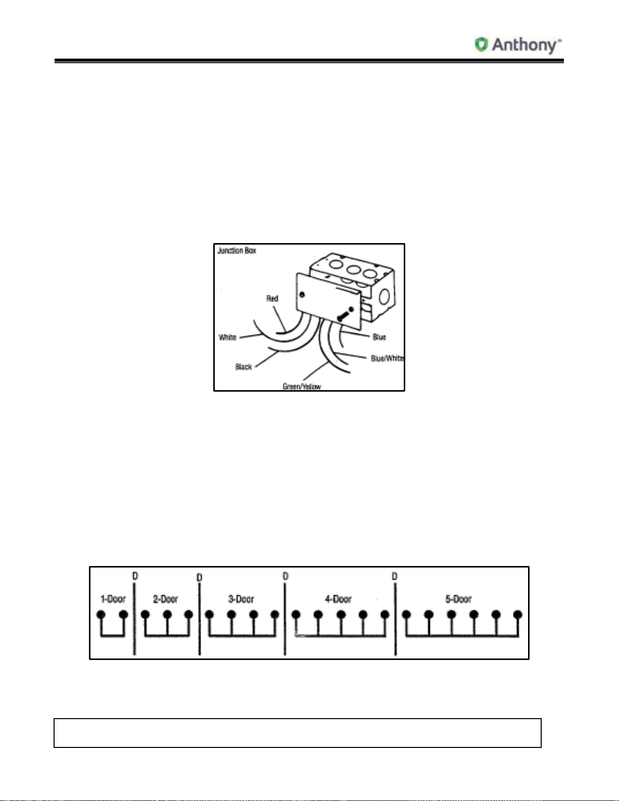
32. P.O.M. Lock Installation ......................................................................................................30
33. P.O.M. Lock Installation ......................................................................................................31
34. Model 101 Glass Replacement (Reglazing) ........................................................................32
35. Ordering Replacement Frames ...........................................................................................35
36. Frame Heater Wire Replacement........................................................................................36
37. Models 101 & 2100 Frame Heater Schematic/Low Temp ...................................................37
38. Models 101 & 2100 Frame Heater Schematic/Normal Temp ..............................................37
39. Humastat Installation Procedure .........................................................................................38
40. Model 101 Humastat ...........................................................................................................40
41. Model 101 & 2100 Shelf Assembly Catalog Size/Shelf Size ...............................................40
42. Models 101 & 2100 Frame & Shelving with Standard Lighting............................................42
43. Models 101 & 2100 Frame & Shelving with “ELS” Electronic Lighting ................................43
44. Four-Post Stabilizer Bar Installation ....................................................................................44
45. Four-Post Shelf System Installation ....................................................................................44
46. Plastic Tag Molding Installation ...........................................................................................46
47. Model 2100 G.F.I. Location & Wiring Diagram ....................................................................47
48. Lamp Replacement .............................................................................................................47
49. Lamp Socket Replacement .................................................................................................48
50. Recessed Light Socket Replacement..................................................................................49
51. Recessed Lamp Channel Replacement with Remote Ballast .............................................49
52. Recessed Lamp Guard Replacement with Remote Ballast.................................................50
53. Recessed Lamp Replacement ............................................................................................50
54. “Boost & Buck” Transformer Wiring Diagram ......................................................................50
55. Frame Junction Box Wiring (Standard Production) .............................................................51
56. Models 101 & 2100 Light Fixture Placement (Prior to 10/93) ..............................................51

Model 101/2100 Doors Service & Installation
TITLE:
99-13312-S001 Model 101/2100 Doors Service &
Installation
REV.
B
Page 4 of 95
57. Models 101 & 2100 Light Fixture Placement – “Continuous” Lineup (10/93 to Present) .....52
58. Models 101 & 2100 Low Temp 120-Volt Remote Ballast and Lamp Wiring Diagram for
1-Light Systems ..................................................................................................................53
59. Models 101 & 2100 Low Temp 120-Volt Remote Ballast and Lamp Wiring Diagram for
2-Light Systems ..................................................................................................................54
60. Models 101 & 2100 Normal Temp 120-Volt Remote Ballast and Lamp Wiring Diagram
for 1- & 2-Light Systems ......................................................................................................55
61. Models 101 & 2100 Normal Temp 120-Volt Remote Ballast and Lamp Wiring Diagram
for 3-Light Systems .............................................................................................................55
62. Normal Temp & Low Temp 120-Volt Ballast and Lamp Wiring Diagram - Pre-Wired 1-
Light System .......................................................................................................................56
63. Ballast Replacement ...........................................................................................................56
64. “ELS” Lamp Socket Replacement .......................................................................................57
65. “ELS” Electronic Ballast Replacement and Wiring Instructions ...........................................59
66. T-8 Lamp Replacement Instructions....................................................................................65
67. Dew Point Chart ..................................................................................................................71
68. Electrical Information for Model 101 Low Temp Heated Doors, Frames & Standard Light
Fixtures Heater Amperages @ 120 Volts ............................................................................72
69. Electrical Information for Model 101 Normal Temp Heated Doors, Frames & Standard
Light Fixtures Heater Amperages @ 120 Volts ...................................................................73
70. Heat Load in BTU/Hr for Model 101 Low Temp Glass, Door Rail, Frame Heaters and
Standard Lighting (Per Door, with Doors Closed @ 75°F Store Ambient)...........................76
71. Heat Load in BTU/Hr for Model 101 Normal Temp Glass, Door Rail, Frame Heaters and
Standard Lighting (Per Door, with Doors Closed @ 75°F Store Ambient)...........................76
72. Heat Load in BTU/Hr for Model 2100 Low Temp Glass, Door Rail, Frame Heaters and
Standard Lighting (Per Door, with Doors Closed @ 75°F Store Ambient)...........................78
73. Electrical Information for Model 2100 Low Temp Heated Doors, Frames & Standard
Light Fixtures Heater Amperages @ 120 Volts ...................................................................79
74. Electrical Information for Model 2100 Normal Temp Doors, Frames & Standard Light
Fixtures Heater Amperages @ 120 Volts ............................................................................80
75. Heat Load in BTU/Hr for Model 2100 Normal Temp Glass, Door Rail, Frame Heaters
and Standard Lights (Per Door, with Doors Closed @ 75°F Store Ambient).......................81
76. Heat Load in BTU/Hr for Model 101 Low Temp Glass, Door Rail, Frame Heaters and
“ELS” Electronic Lighting System (Per Door, with Doors Closed @ 75°F Store Ambient) ..82

Model 101/2100 Doors Service & Installation
TITLE:
99-13312-S001 Model 101/2100 Doors Service &
Installation
REV.
B
Page 5 of 95
77. Electrical Information for Model 101 Low Temp Doors, Frames & “ELS Electronic
Lighting System Heater Amperages @ 120 Volts ...............................................................83
78. Electrical Information for Model 101 Normal Temp Doors, Frames & “ELS” Electronic
Lighting System Heater Amperages @ 120 Volts ...............................................................84
79. Heat Load in BTU/Hr for Model 101 Normal Temp Glass, Door Rail, Frame Heaters and
“ELS” Electronic Lighting System (Per Door, with Doors Closed @ 75°F Store Ambient) ..87
80. Electrical Information for Model 2100 Low Temp Doors, Frames & “ELS” Electronic
Lighting System Heater Amperages @ 120 Volts ...............................................................88
81. Heat Load in BTU/Hr for Model 2100 Normal Temp Glass, Door Rail, Frame Heaters and
“ELS” Electronic Lighting System (Per Door, with Doors Closed @ 75°F Store
Ambient)..............................................................................................................................89
82. Heat Load in BTU/Hr for Model 2100 Low Temp Glass, Door Rail, Frame Heaters and
“ELS” Electronic Lighting System (Per Door, with Doors Closed @ 75°F Store Ambient) ..90
83. Electrical Information for Model 2100 Normal Temp Doors, Frames & “ELS” Electronic
Lighting System Heater Amperages @ 120 Volts ...............................................................90
84. Troubleshooting ..................................................................................................................92
85. Safety Precautions ..............................................................................................................94
86. Tips .....................................................................................................................................94
Model 101/2100 Doors Service & Installation
TITLE:
99-13312-S001 Model 101/2100 Doors Service &
Installation
REV.
B
Page 6 of 95
s: 199
1 to
Description
Description
Description
Description
1. Hinge Pin
11. Female Receptacle
21. Bottom Lamp Socket
31. Light Fixture
2. Molded Hinge Pin (’91)
12. Magnetic Gasket
22. Bulb
32. Contact Plate
3. Corner Screw
13. Magnet
23. Torquemaster
33. Contact Plate
4. Corner Piece
14. Torque Rod
24. Junction Box
34. Door Extrusion
5. Door Extrusion
15. Double Socket
25. Single Receptacle
35. Retainer
6. Heater Wire
16. Double Receptacle
26. Single Socket
7. Hold-Open (’86-90)
17. Frame Extrusion
27. Raceway Cover
8. Hold-Open (’90)
18. Installation Hole
28. Raceway Cover
9. Door Cover
19. Installation Screw
29. Raceway
10. Door Handle
20. Top Lamp Socket
30. Frame Mullion
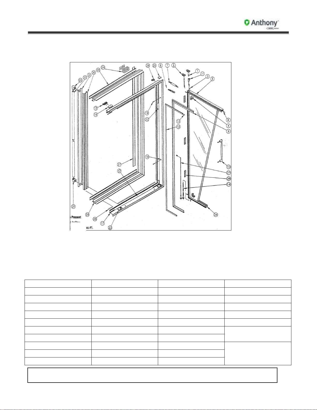
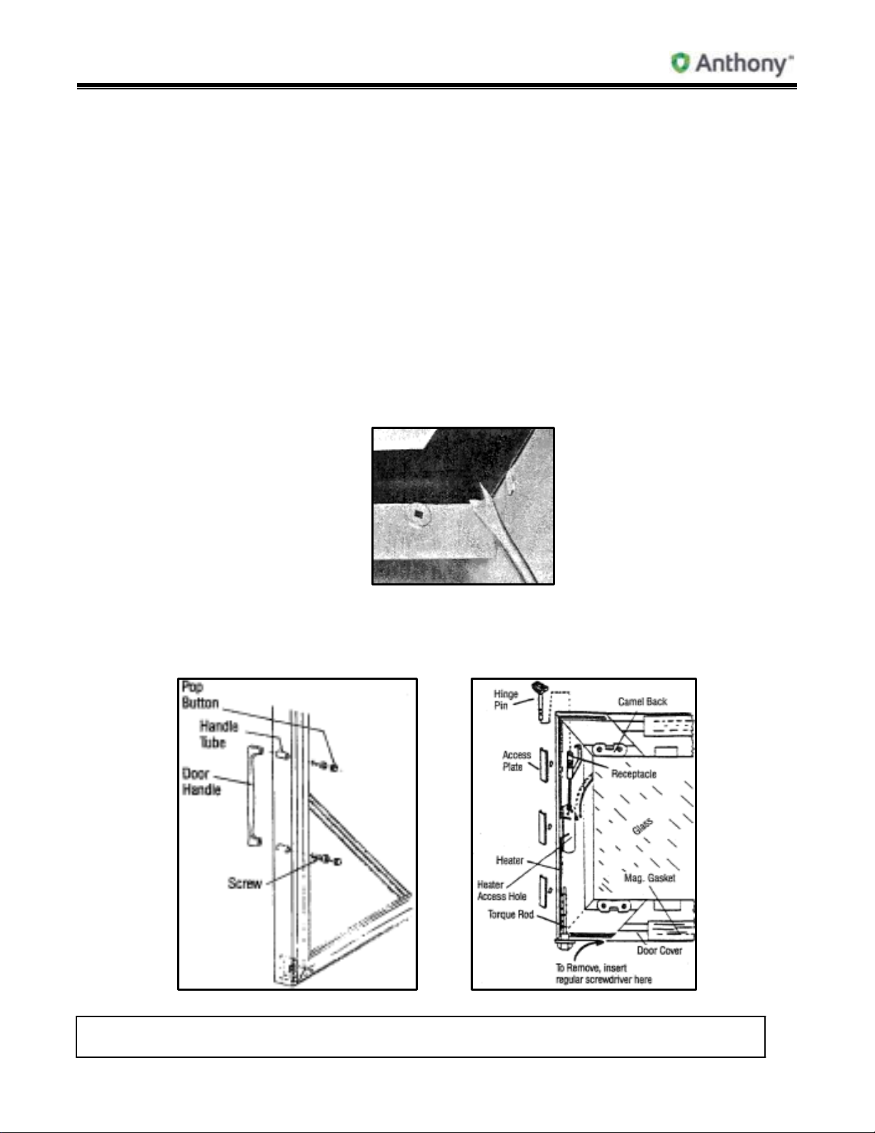
1. Models 101 & 2100 Door & Frame – Reversible Parts Placement
(Start 10/89)
Change Present
1. Hinge Rail is hollow.
2. Use #2 Hinge Pin; replaces #1.
3. Delete #11 Receptacle.
4. Single hinge side Access Hole in center of Hinge Rail only. Delete #36.
36. Access Hole Cover
Plate
37. Torque Rod (Right
Angle)
Model 101/2100 Doors Service & Installation
TITLE:
99-13312-S001 Model 101/2100 Doors Service &
Installation
REV.
B
Page 7 of 95
Description
Description
Description
1. Corner Piece
7. Gasket
13. Cap
2. Corner Screw
8. Camel Back
14. Access Tube
3. Glazing Channel
9. Hinge Pin
15. Handle
4. Heater Wire
10. Receptacle
16. Handle Screw
5. Door Rail
11. Cover
17. Molded Hinge Pin
6. Plastic
12. Torque Rod
18. Torque Rod
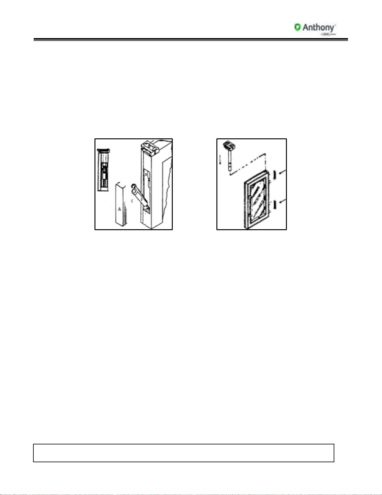
2. Models 101 & 2100 Reversible Door Parts Placement (1989 to 1991)
Changes: 1991 to Present
1. Hinge Rail is hollow.
2. Use #17 Hinge Pin; replaces #9.
3. Delete #10 Receptacle.
4. Use #18 Torque Rod; replaces #12
5. Single hinge side Access Hole in center of Hinge Rail only. Delete #11.
Model 101/2100 Doors Service & Installation
TITLE:
99-13312-S001 Model 101/2100 Doors Service &
Installation
REV.
B
Page 8 of 95
A B C D
MULLION
NET OPENING
FLANGE
NET OPENING
A B C D
MULLION
NET OPENING
FLANGE
NET OPENING
A B C D
MULLION
NET OPENING
FLANGE
NET OPENING
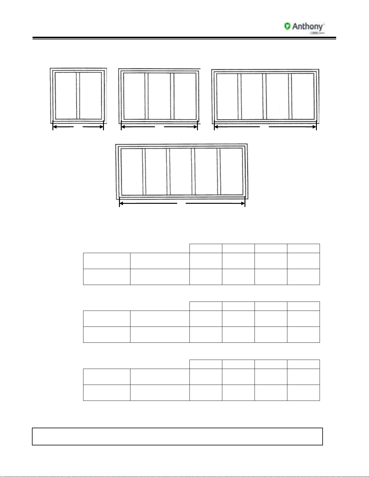
3. Models 101 & 2100 Standard (Before 7/94) Frame Net Opening Widths
A B C
TWO-DOOR FRAME THREE-DOOR FRAME FOUR-DOOR
FRAME
3.1. Frame Width Data
FIVE-DOOR
3.1.1. 24” Door (Catalog Size) 23-3/16” Actual Door Width
ENDLESS
FINISHED FRAME
D
FRAME
48-5/8” 72-3/8”
96-1/8” 119-7/8”
FULL
3.1.2. 26” Door (Catalog Size) 26-3/8” Actual Door Width
FINISHED FRAME
48-7/8” 72-5/8”
96-3/8” 120-1/8”
ENDLESS
FULL
FINISHED FRAME
FINISHED FRAME
55-1/4” 82-3/16” 109-1/8” 136-1/16”
55-1/2” 82-7/16” 109-3/8” 136-5/16”
3.1.3. 30” Door (Catalog Size) 29-7/8” Actual Door Width
ENDLESS
FULL
FINISHED FRAME
FINISHED FRAME
62”
92-7/16” 122-7/8” 153-5/16”
62-1/4” 92-11/16” 123-1/8” 153-9/16”
Model 101/2100 Doors Service & Installation
TITLE:
99-13312-S001 Model 101/2100 Doors Service &
Installation
REV.
B
Page 9 of 95
CATALOG DOOR HEIGHT
75” 73” 67” 63”
FINISHED FRAME
74-13/16”
72-13/16”
66-13/16”
64-9/16”
NET OPENING HEIGHT
75” 73” 67”
64-3/4”
CATALOG WIDTH
CATALOG HEIGHT
24” 26” 30” 75” 73” 67” 63”
ACTUAL SIZE
23-3/16”
26-3/8”
29-7/8”
73-1/16”
71-1/16”
65-1/16”
62-13/16”
4. Models 101 & 2100 Standard Frame Net Opening Heights
4.1. Frame Height Data
4.2. Door Size
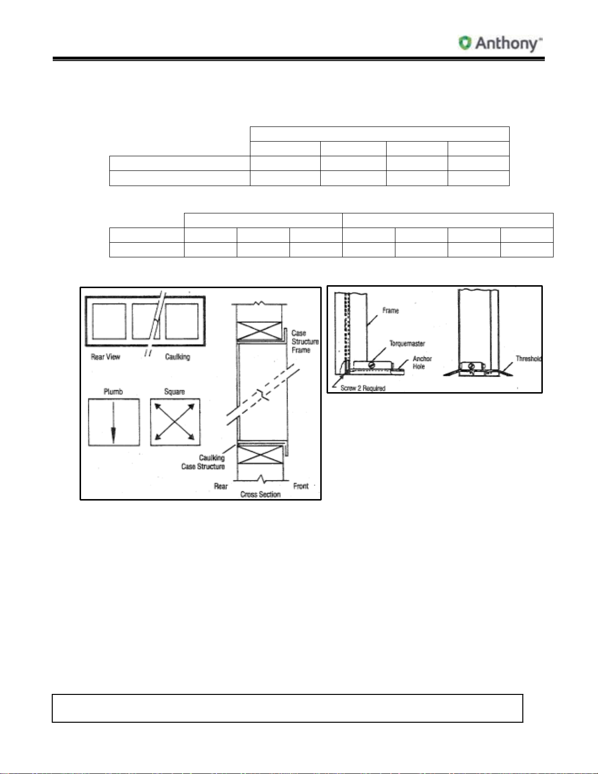
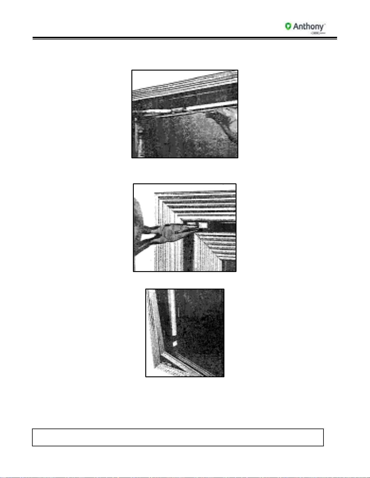
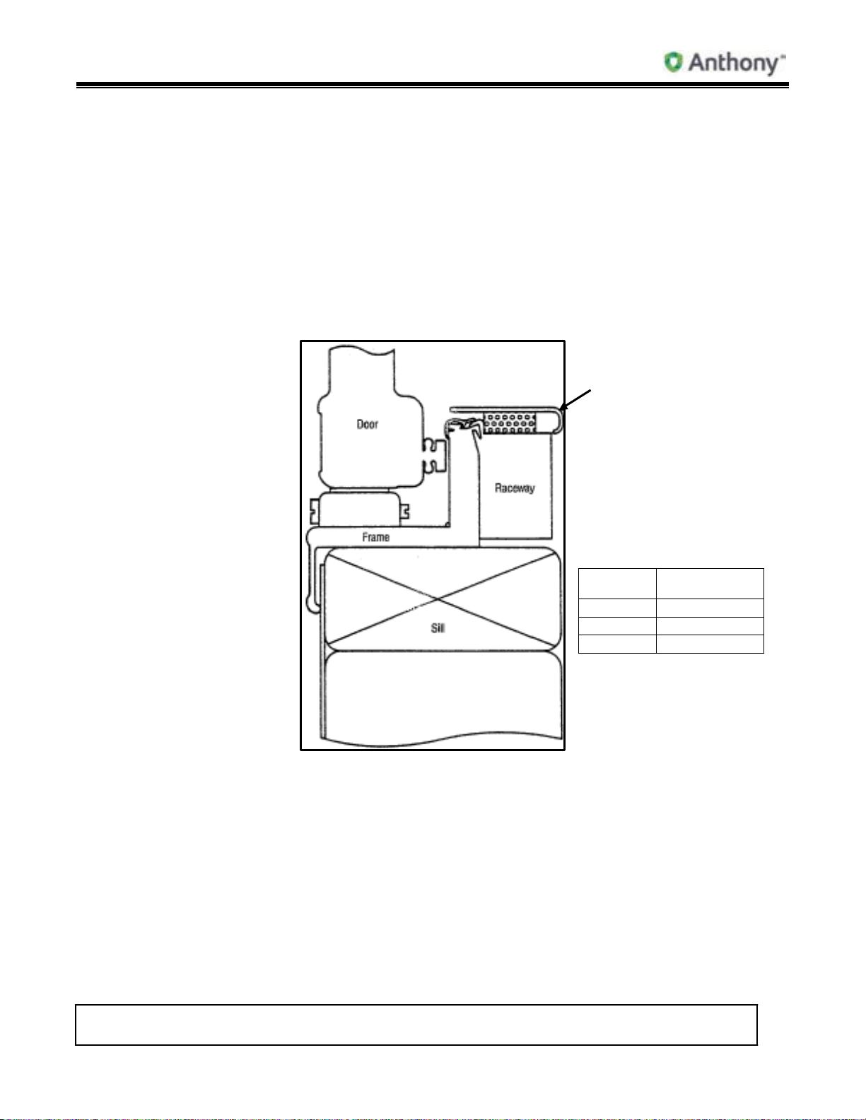
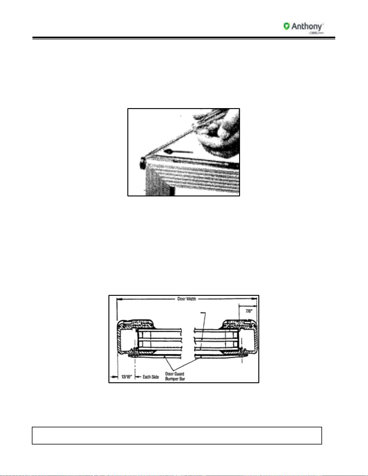
5. Models 101 & 2100 Frame Installation
1. Read instructions completely before installing frames.
2. Openings must conform to net openings listed in Price Book or other.
3. Check size of finished frame to net opening.
4. Do not force frame into tight opening.
5. Check net opening for plumb and square as shown. Sill must be level left to right and
front to back.
a. Jambs, header and sill should be wood for a secure installation
b. Anthony door frame needs a sill of at least 1-1/2” for proper installation.
Frame Installation Pass-Thru Cross Section (w/wo Threshold)

Model 101/2100 Doors Service & Installation
TITLE:
99-13312-S001 Model 101/2100 Doors Service &
Installation
REV.
B
Page 10 of 95
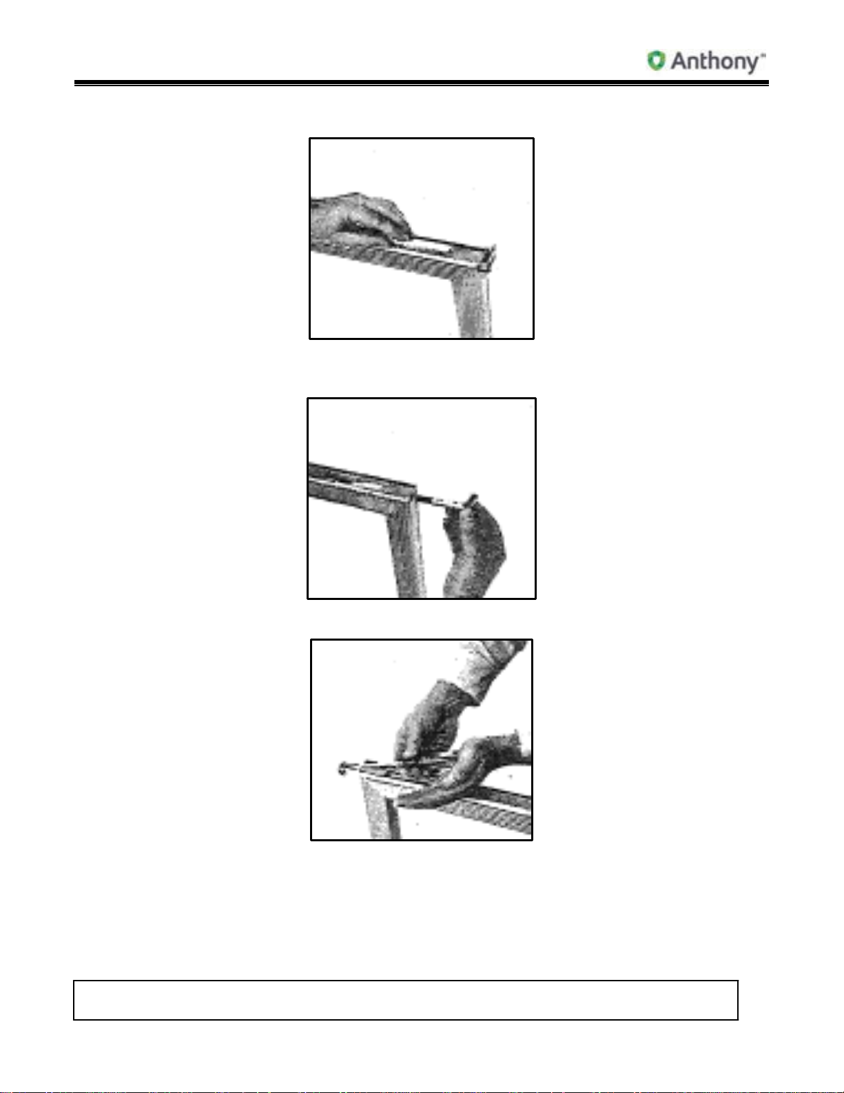
6. Set frame in net opening. For safety, partially install wood screws in top of frame. Do
not tighten. Torquemaster (silver rectangular box) goes at bottom of frame; hinge pin
to top of frame.
7. Check frame for square, as shown. Shim as necessary. Ensure that shims are placed
as close to installation holes as possible. When shimming is necessary, shim top and
bottom and/or left end of frame and right end of frame to maintain square of frame in
net opening.
Continuous Lineup Frames:
8. Set next frame into case opening and snug frame against right side of first frame.
9. Square and plumb second frame. For safety, partially install wood screws in top of
frame.
10. Insert sex bolts through right side of first frame, into left side of second frame.
Tighten until frames are pulled together.
11. From inside of case, caulk all four sides of frame, between frame and opening.
12. Starting with frame sill, install mounting screws and tighten, then do sides and top.
Do not over-tighten top screws, as this will bow frame.
13. From inside the case, re-check caulking.
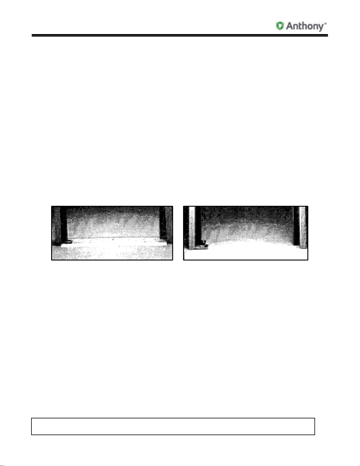
6. Frame Divider Board Installation (Prior to 1993)
Instructions are for multiple full flange frame lineups.
Frames are shipped with divider board taped to end of frame.
Divider board is pre-cut to given net opening height. For example, a 75” net opening will
get a 75” divider board, and a 67” net opening will get a 67” divider board.
If net opening height varies, make up the difference with a solid shim.
1. Set frame into case opening and push frame tight against left side of opening. Square
and plumb frame. Install installation screws on bottom of frame, left end of frame and
top of frame.
2. Insert divider board behind flange on right side of frame. Toenail divider board to sill
and header, if possible. (Metal cover plate is on customer side.) Screw right end of
frame to divider board.
3. Set next frame into net opening and snug frame against divider board. Install screws
through left side of frame into divider board.
4. When adding divider boards and frame sections, always make sure frames are plumb
and square.
5. Continue adding frames and divider boards to complete line-up.
6. Divider boards must be snug between sill and header.
Model 101/2100 Doors Service & Installation
TITLE:
99-13312-S001 Model 101/2100 Doors Service &
Installation
REV.
B
Page 11 of 95
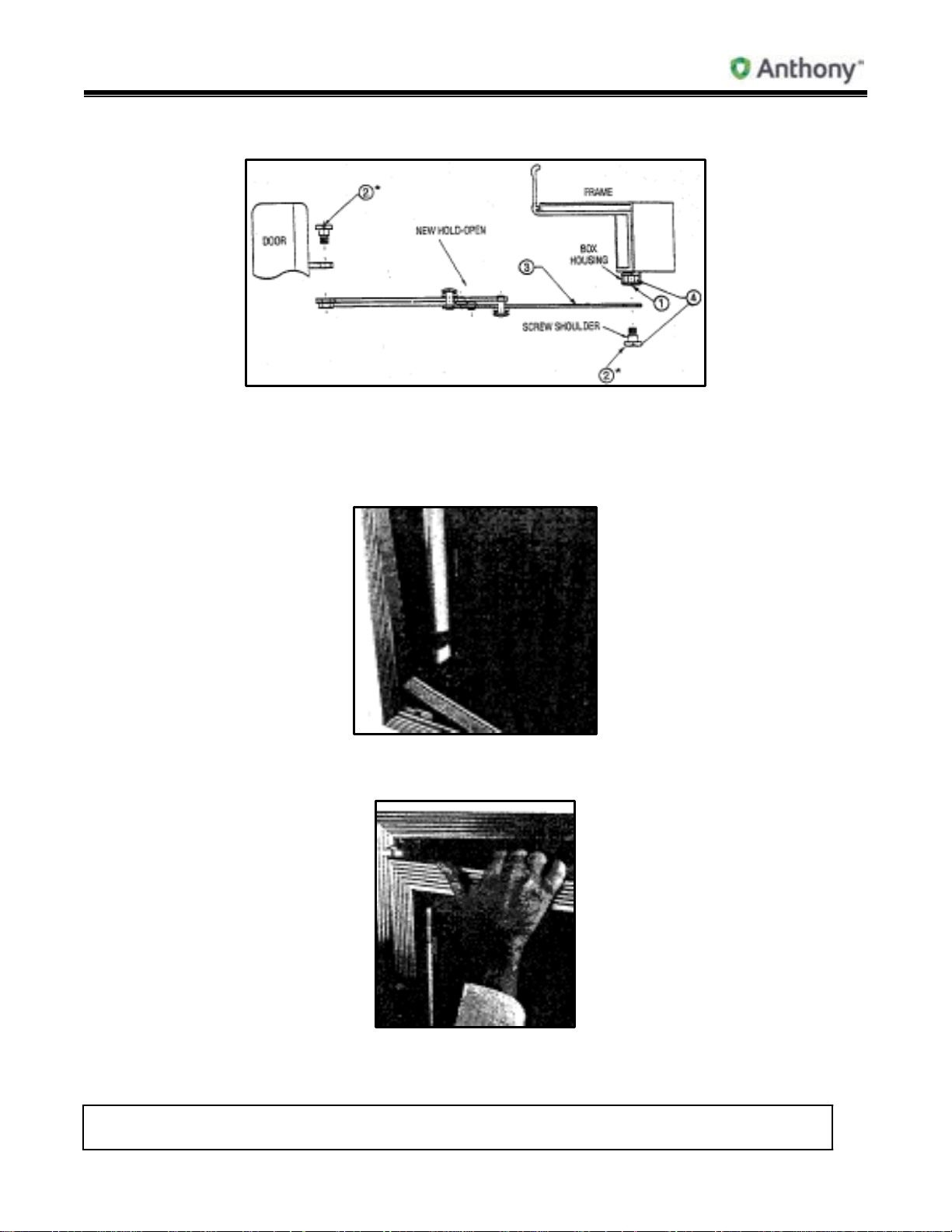
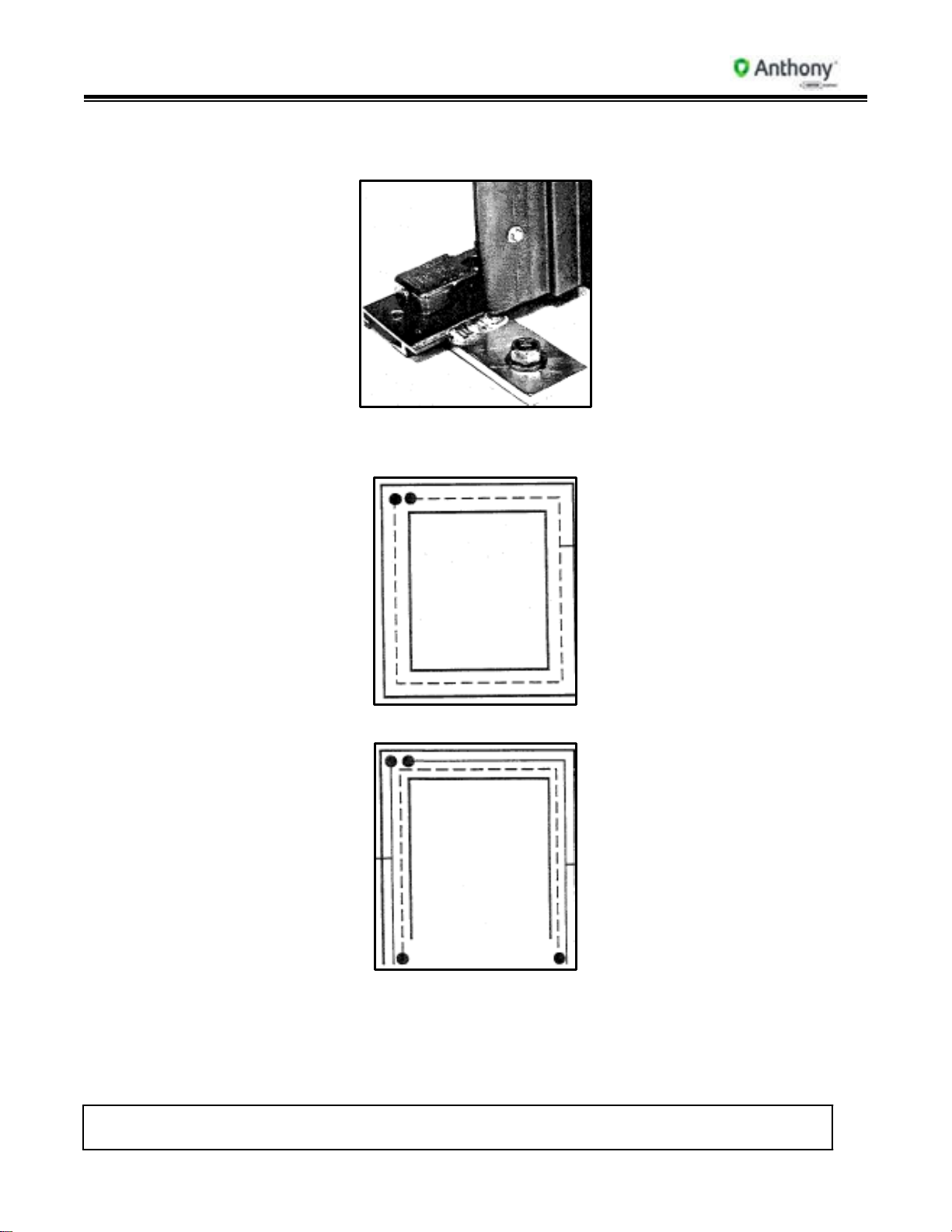
7. Reversible/Cordless Door & Hold-Open Installation
Model 101 and 2100 Hold-Open
Note: Replace spare shoulder screw (#2) in spare box housing nut (#4) when
installing or reversing a door.
1. Align door with torque rod and insert into the Torquemaster socket at base of door.
2. Engage door with hinge pin plug inserted into hinge pin plug receptacle at top of
frame.
Instructions
Model 101/2100 Doors Service & Installation
TITLE:
99-13312-S001 Model 101/2100 Doors Service &
Installation
REV.
B
Page 12 of 95
3. Push door into top frame with thumb until hinge pin plug snaps into place.
4. Adjust closing force by turning the screw on the front of the Torquemaster with a flathead screwdriver. Turn counter-clockwise to tighten, clockwise to loosen.
5. If necessary to square door in frame opening, turn end screw on Torquemaster
(marked SAG ADJ) with a flat-head screwdriver.
6. Do not use power tools for installation or removal.
8. Reversing Frame Hardware
1. Remove Torquemaster by turning center screw counter-clockwise.
Model 101/2100 Doors Service & Installation
TITLE:
99-13312-S001 Model 101/2100 Doors Service &
Installation
REV.
B
Page 13 of 95
2. Remove back cover plate with flat-head screwdriver and insert into opposite
Torquemaster hole. Replace and re-install Torquemaster in new position.
3. Insert back safety cover plate into opposite side hinge receptacle.
4. Do not use power tools for installation or removal.
9. Door Reversing Instructions Models 101 & 2100 (1989-1991)
1. Release tension on Torquemaster by turning front screw clockwise.
Model 101/2100 Doors Service & Installation
TITLE:
99-13312-S001 Model 101/2100 Doors Service &
Installation
REV.
B
Page 14 of 95
2. On Hold-Open (1990 to Present), remove shoulder screw from camel back hinge on
back of door (Model 101 and 2100 Hold-Open Instructions).
3. Remove hinge pin plug from frame by inserting needle-nose pliers into hinge pin plug
1/8” hole. Compress and pull hinge pin plug away from frame.
4. Lift door out of Torquemaster. Lean door on its side against a stable surface.
Model 101/2100 Doors Service & Installation
TITLE:
99-13312-S001 Model 101/2100 Doors Service &
Installation
REV.
B
Page 15 of 95
5. Remove hinge pin plug access cover from hinged side of door.
6. Disengage safety snap from female plug, remove male plug from door and insert in
opposite end of door.
7. Remove torque rod by sliding it out bottom of door and insert in opposite end of door.
8. Model 101 & 2100 have only one female receptacle. When reversing door, also
reverse receptacle. Pull receptacle from one end and feed back down through
opposite end.

Model 101/2100 Doors Service & Installation
TITLE:
99-13312-S001 Model 101/2100 Doors Service &
Installation
REV.
B
Page 16 of 95
9. Carefully replace hinge pin access covers.
10. Do not use power tools for installation or removal.
11. See Model 101 & 2100 torque rod below.
10. Door Reversing Instructions (1991 to Present)
Door Quick Disconnect and
1. Reverse door hardware.
a. Remove cover plate from center hinge side of door.
b. Disconnect hinge pin connectors from door heater and/or glass heater connectors.
c. Pull hinge pin out through top of door.
Reversing
Model 101/2100 Doors Service & Installation
TITLE:
99-13312-S001 Model 101/2100 Doors Service &
Installation
REV.
B
Page 17 of 95
d. Remove torque rod from bottom of door; pull rod down and out.
e. Insert torque rod in opposite end of door.
f. Insert hinge pin in opposite end of door.
g. Plug in hinge pin connectors to door heaters and/or glass heaters.
2. Wiring Instructions:
Heated Glass:
a. If glass is heated, unplug Black and White lead wires from glass.
b. To re-connect heated glass, plug in Black and White lead wires coming off heater
loom to Black and White lead wires from glass.
Non-Heated Glass:
a. Connect Black or Red lead wires from hinge pin to Black or Red door heater lead.
b. Connect White lead wire from hinge pin to White door heater lead.
4. Re-install door.
3. Replace hinge side cover plate.
11. Models 103, 105, 107, 2125, 2127 & 2130 Pass-Thru Installation
With Threshold Without
Note: If a roll-a-way cart is included in order, it must be behind the door before
installing frame.
1. Refer to Frame Installation instruction to install frame.
2. When threshold is desired, drill and tag on pre-drilled mounting holes only.
3. For installation of door and hold-open, use Reversible/Cordless Door & Hold-Open
Installation instructions.
4. With door in closed position, adjust floor wiper seal to fit flush with door and/or slab.
Turn screws clockwise to tighten and counter-clockwise to loosen.
Threshold
Model 101/2100 Doors Service & Installation
TITLE:
99-13312-S001 Model 101/2100 Doors Service &
Installation
REV.
B
Page 18 of 95
5. For additional bottom support, Anthony Pass-Thrus are equipped with a base plate
and two special floor anchor bolts.
6. Pass-Thru Frame Wiring Diagrams
a. With Threshold
Heater Wire
b. Without Threshold
White
Lead Wire
Black
Lead Wire
11.1. Pass-Thru 101 Model Numbers
1. Model 103: All glass or all solid panel.
2. Model 105: 1/3 glass, 2/3 solid panel.
3. Model 107: All glass with Roll-A-Way cart.
Model 101/2100 Doors Service & Installation
TITLE:
99-13312-S001 Model 101/2100 Doors Service &
Installation
REV.
B
Page 19 of 95
DOOR SIZE
30”
26-3/4”
11.2. Pass-Thru 2100 Model Numbers
1. Model 2130: All clear glass with colored border, or all glass with solid color.
2. Model 2125: 1/3 clear glass, 2/3 solid color glass.
3. Model 2127: All clear glass with colored border, and Roll-A-Way cart.
12. Frame Sill Plastic protector Installation Models 101 & 2100
1. Set metal protector on sill inside of case between clear opening of frame, with curved
edge over bottom sill plastic.
2. Stick frame guard to top of bottom raceway with two-way tape provided.
Frame Guard
TA0432D
CATALOG
GUARD LENGTH
24” 19-1/2”
26” 23-1/4”
NOTE: Foam 5/16” x 3/4” Polyethelene #8302 unless otherwise specified.
Model 101/2100 Doors Service & Installation
TITLE:
99-13312-S001 Model 101/2100 Doors Service &
Installation
REV.
B
Page 20 of 95
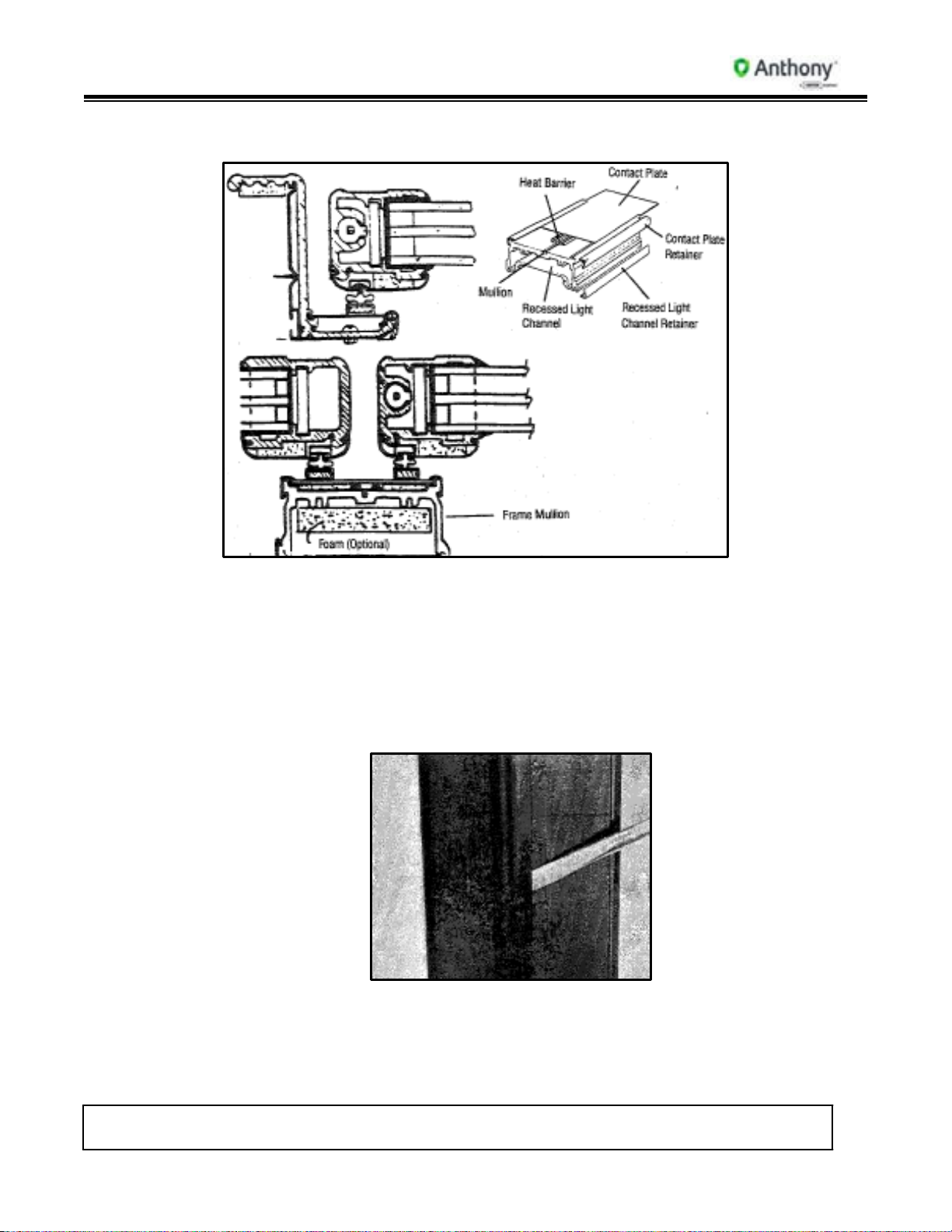
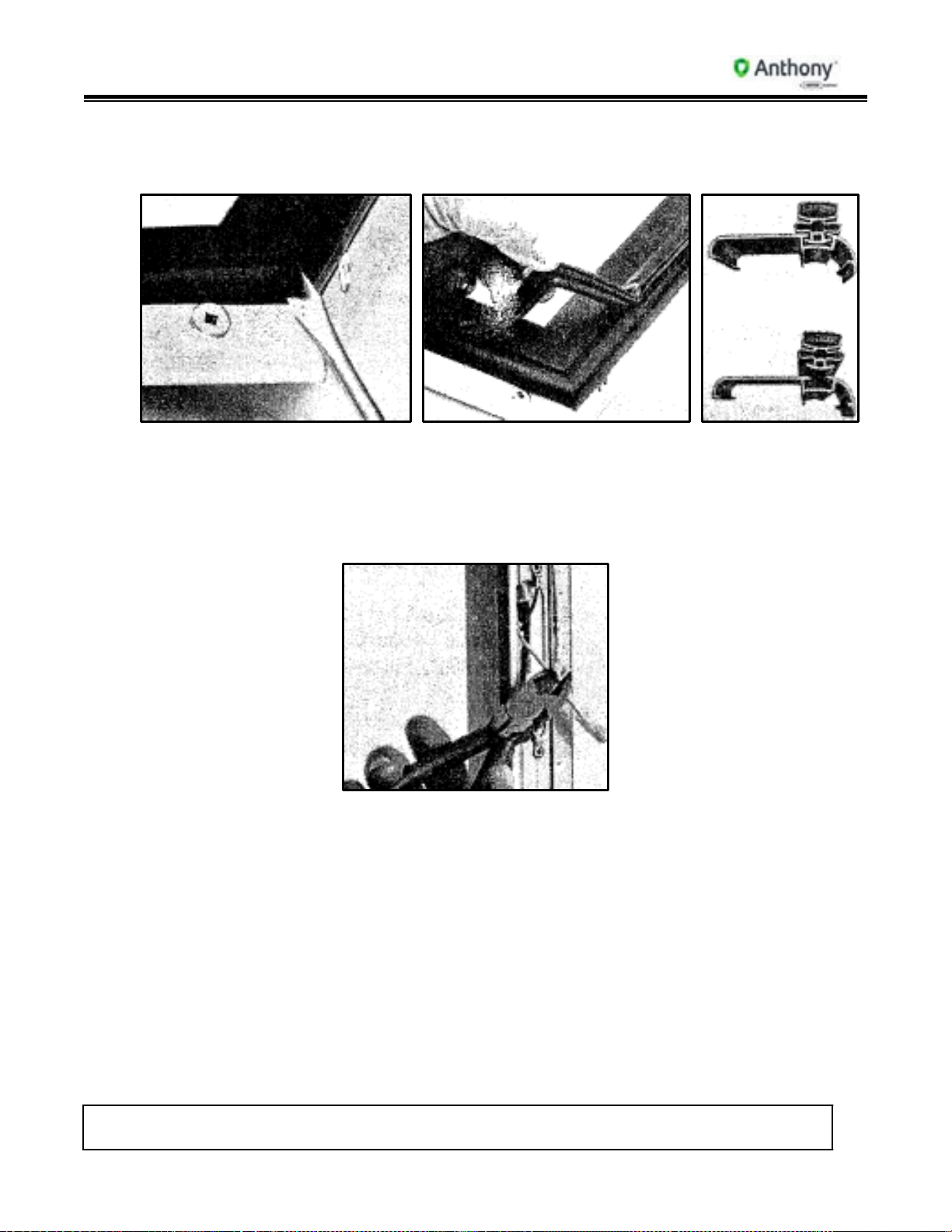
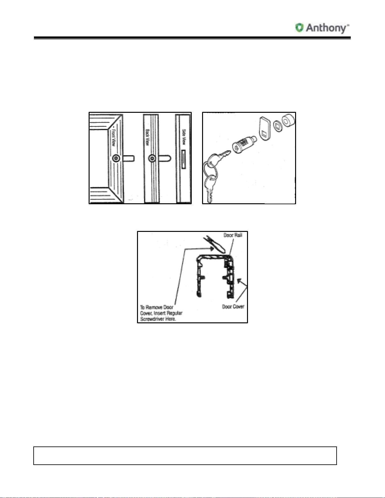
13. Contact Plate and Contact Plate Retainer Replacement
Note: In the illustration above, Model 100R is shown. Model 100FR is the same
except for the mullion and mullion contact plate. Model 101 is the same except
for the mullion cover as shown in Door Quick Disconnect and Reversing.
1. Remove door.
2. To remove contact plate and contact plate retainer, insert flat-head screwdriver under
side back edge of retainer plastic.
Pull up to unsnap retainer from mullion and perimeter of frame. Remove contact plate.
Frame heaters are now exposed.
End and Center Mullion (1987 to Present)
Model 101/2100 Doors Service & Installation
TITLE:
99-13312-S001 Model 101/2100 Doors Service &
Installation
REV.
B
Page 21 of 95
3. To replace retainer and contact plate, lay contact plate flat on frame rail, insert top
front leg edge of retainer between the contact plate and the mullion. Snhap retainer on
back edge of mullion and perimeter of frame.
4. Contact plate for prewired ballast frame is 3-7/16” wide. Contact plate for nonprewired frames is 2-1/2” wide.
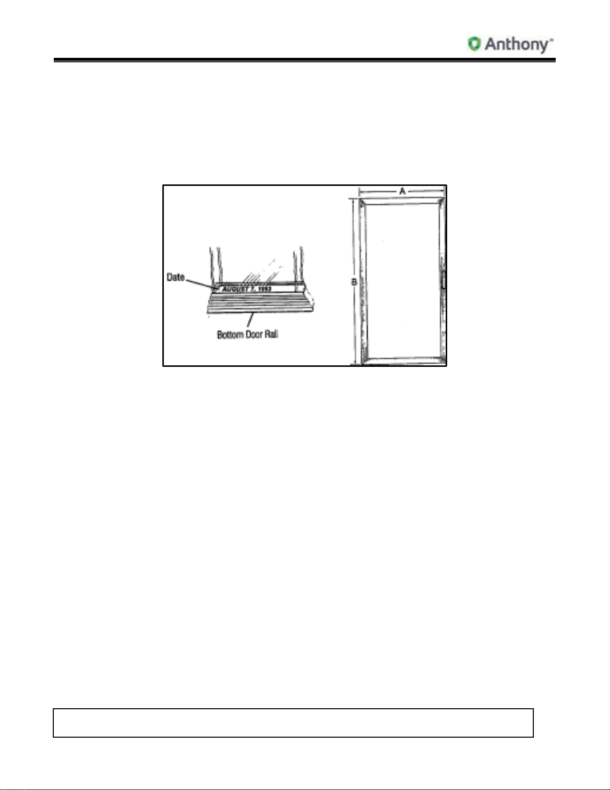
14. Ordering Replacement Doors
Replacement Doors (All Swing Door
1. Specify outside dimensions of door (measure to nearest 1/16”).
2. With or without heaters?
3. Hinge swing; left or right?
4. Specify model: Cooler or Freezer?
5. Specify finish.
6. Specify any custom items in the original order.
7. Specify date of original order and/or Anthony confirmation/invoice number. (Original
manufacture date is stamped on metal spacer bar between panes of glass, as shown
above.
8. With or without locks?
9. Specify voltage.
Models)
Model 101/2100 Doors Service & Installation
TITLE:
99-13312-S001 Model 101/2100 Doors Service &
Installation
REV.
B
Page 22 of 95
15. Torquemaster Replacement
Torquemaster
1. Torquemaster is used on all standard production frames.
2. To remove, insert flat-head screwdriver into top center cutout in Torquemaster and turn
screw 1/8” turn. If necessary, insert small flat-head screwdriver between edge of
Torquemaster and frame and gently pry up.
3. Reverse instructions to replace.
16. Door Gasket Replacement
Door
Gasket
1. Remove old gasket by starting in corner, gently pulling gasket away from plastic.
Model 101/2100 Doors Service & Installation
TITLE:
99-13312-S001 Model 101/2100 Doors Service &
Installation
REV.
B
Page 23 of 95
2. Model 101 To replace gasket, remove top and bottom door plastic and slide the
gasket up the two verticals. Slide top and bottom plastic onto gasket and
replace top and bottom plastic on door rail. Tuck in corners of gasket with
a flat-head screwdriver.
Model 2100 Lay new gasket over track in back of door rail. With a single-edged plastic
roller, roll in the outside edge of door gasket first, then the inside edge.
Tuck in all four corners.
3. Reverse instructions to replace.
17. Door Plastic (Cover) Replacement
1. Starting in corner, gently pull rubber gasket away from door plastic.
2. With gasket removed, insert flat-head screwdriver under outside edge of plastic and
gently pry up. At either end of plastic, run screwdriver the complete length and width of
door rail. With outside edge of plastic released, push plastic toward glass to remove.
3. To replace, insert inside edge of plastic into inside door rail groove. Snap outside edge
of plastic over outside edge of door rail.
18. Door Cut-Away & Handle Replacement
Handle Replacement Door Cut-Away
Model 101/2100 Doors Service & Installation
TITLE:
99-13312-S001 Model 101/2100 Doors Service &
Installation
REV.
B
Page 24 of 95
1. Model 101 Remove plastic hole plug from back of door plastic.
2. Insert 5/32” Allen wrench into access holes and turn screws counter-clockwise to
remove.
3. Reverse instructions to replace handle.
4. Model 2100 Remove screws on side of door rail
5. Reverse instructions to re-install.
19. Side Access Plate Replacement (1989 to 1991)
Hinge Pin and Cover Plate Hinge Pin Removal
Note: Lead Wires: Heater (Black, White), Receptacle (Black, White, Green), Glass
(Black, White).
1. Side access plate is located at top side of door.
2. To remove, insert flat-head screwdriver under edge of cover and lift up.
3. Snap plate into door extrusion to replace.
20. Side Access Plate Replacement (1991 to Present)
1. Access plate is located on the center of the hinge rail (Door Quick Disconnect and Reversing).
2. To remove side access plate, insert small flat-head screwdriver under edge of cover
and lift up.
3. Snap plate into door extrusion to replace.
Model 101/2100 Doors Service & Installation
TITLE:
99-13312-S001 Model 101/2100 Doors Service &
Installation
REV.
B
Page 25 of 95
21. Door Female Plug Replacement (1989 to 1991)
1. Model 101 Only – Gently insert flat-head screwdriver under edge of top side access
plate and pull up to remove (Hinge Pin and Cover Plate/Door Cut-Away).
2. Unsnap hinge pin from female receptacle.
3. Female plug is installed with additional lead wire. Pull female plug out through access
hole and cut Black, White and Green/Yellow lead wires.
4. Reverse instructions to replace door female plug. Re-wire Black to Black, White to
White and Green/Yellow to ground.
5. Replace side access plate.
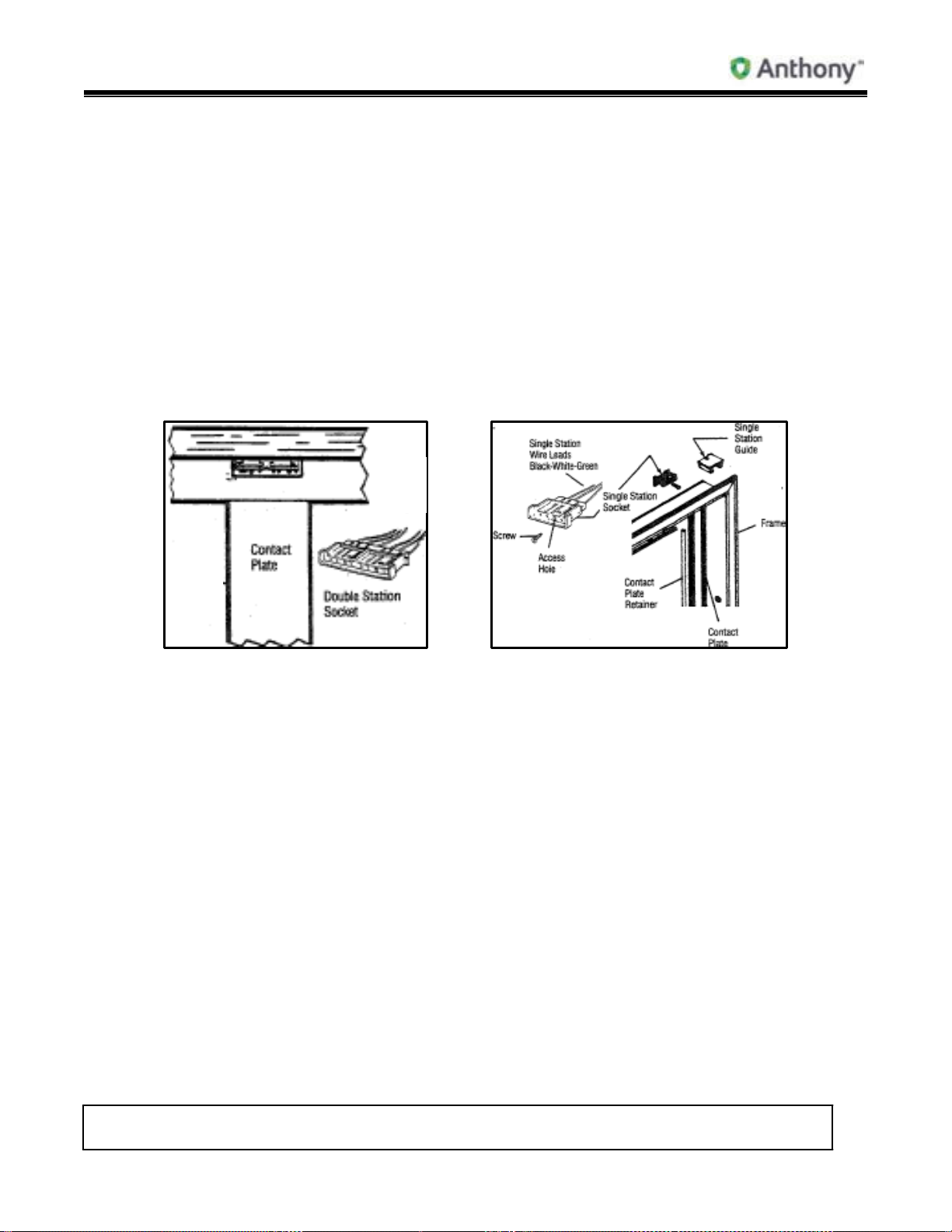
22. Frame Female Plug and/or Socket Replacement (1991 to Present)
Double Station Socket Single Station
Model 100R, 100FR, 101 (1989) Model 100R, 100FR, 101 (1987 to Present)
Note: Double Station Socket Wire Leads – 2 Reds, 2 Whites, 2 Greens
1. Model 101 Only – Frame female plug is removed through front side of frame.
2. Insert small Phillips-head screwdriver into round access hole in face of female plug, and
turn screw counter-clockwise to remove. For double station socket replacement,
remove two screws out through front.
3. Female plug has extra length wire leads in raceway for easy placement.
4. Pull plug out front and cut lead wires: Black-White, and Green/Yellow.
5. Reverse instructions to re-wire: Black to Black, White to White and Green/Yellow to
ground.
Socket
Model 101/2100 Doors Service & Installation
TITLE:
99-13312-S001 Model 101/2100 Doors Service &
Installation
REV.
B
Page 26 of 95
23. Door Heater Replacement (1989 to 1991) Model 101 Only
1. Remove door gasket and plastic.
2. Remove side access plate (Door Cut-Away).
3. Unsnap hinge pin from female receptacle.
4. Wiring for the door is done in the center side of hinge rail.
5. To remove heater, cut solid lead wires: Black, White and Green/Yellow (ground).
6. Heater wire lies in track on the back outside edge of door. Pull heater out.
7. If glass is heated, cut Black and White lead wires from glass.
8. Reverse instructions to replace door heater. Wire Black to Black, White to White and
Green/Yellow to ground. If heated glass is used, reconnect glass Black and White lead
wires to heater Black and White lead wires.
24. Door Heater Replacement (1991 to Present) Model 101 Only
1. Remove door plastic and door gasket.
2. Remove center side access plate (Door Quick Disconnect and Reversing).
3. To remove heater, unplug solid lead wires: Black or Red, White and Yellow/Green
(ground).

Model 101/2100 Doors Service & Installation
TITLE:
99-13312-S001 Model 101/2100 Doors Service &
Installation
REV.
B
Page 27 of 95
4. If glass is heated, unplug Black and White solid wires from glass.
5. Heater wire lies in track on the back outside edge of door. Pull heater out.
6. Reverse instructions to replace door heater. Plug in Black or Red lead wire from hinge
pin to Black or Red lead wire from heater, White lead wire from hinge pin to White
heater lead and Green/Yellow lead from hinge pin to ground.
Note: If glass is heated, plug in Black and White lead wires coming off heater loom to
Black and White lead wires from glass.
7. Replace side access plate.
8. Replace door plastic and gasket.
25. Hinge Pin Replacement (1989 to 1991)
1. Model 101 - Remove top side access plate (Door Cut-Away).
Note: Lead Wires: Heater (Black, White), Receptacle (Black, White, Green), Glass
(Black, White).
2. Unsnap female receptacle from hinge pin and remove hinge pin out through top door
rail.
3. Reverse instructions to replace.
26. Hinge Pin Replacement (1991 to Present)
1. Model 101 & 2100 - Remove center hinge side access plate (Door Quick Disconnect and
Reversing
).
2. Unplug Black or Red lead wire from hinge pin from Black solid heater wire lead.
3. Unplug White lead wire from hinge pin from White solid heater wire lead.
4. Unplug Green/Yellow (ground) lead wire.
5. If glass is heated, unplug Black and White lead wire on heater loom from Black and
White lead wire from glass.
6. Pull hinge pin out through top of door.
7. Reverse instructions to replace.
27. Wiring Instructions, Heated & Non-Heated Glass (1991 to Present)
1. Heated Glass – Connect Black or Red lead wire from hinge pin to Black lead wire from
glass and Red or Black lead wire from door heater (Door Quick Disconnect and Reversing).
2. Connect White heater lead wire from hinge pin to glass White lead wire.
3. Non-Heated Glass – Connect Black or Red lead wire from hinge pin to Black or Red
door heater lead.
4. Connect White lead wire from hinge pin to White door heater lead.
Model 101/2100 Doors Service & Installation
TITLE:
99-13312-S001 Model 101/2100 Doors Service &
Installation
REV.
B
Page 28 of 95
5. Replace hinge side cover plate.
6. Re-install door.
28. Torque Rod Replacement (1987 to 1991)
1. To remove torque rod, use flat-head screwdriver. Catch edge of torque rod shaft and
tap rod down and out through bottom of door.
2. Reverse instructions to replace.
29. Torque Rod Replacement (1991 to Present)
1. To remove torque rod, use flat-head screwdriver. Catch edge of torque rod shaft with
screwdriver and tap rod down into place (Door Quick Disconnect and Reversing).
2. To replace, slide end of rod up hinge rail, then insert square shaft of torque rod into
square hole in door rail. Tap into place.
Note: Torque rod has no tip.
30. Front Bumper Bar Field Installation
Front Bumper
1. Order door guards 1” smaller than actual door width.
2. Specify finish (Gold/Silver).
Bar
Model 101/2100 Doors Service & Installation
TITLE:
99-13312-S001 Model 101/2100 Doors Service &
Installation
REV.
B
Page 29 of 95
3. Anthony provides pre-drilled screw holes in bar. Customer must drill a #30 or 1/8” hole
in door rail 13/16” from each side of door rail.
4. Screws for mounting bar are self-tapping. Screws are not to exceed 3/8” in length.
5. Mount bar at desired vertical height to protect door glass.
31. Model 101 Door Cylinder Lock Replacement or Repair
Cylinder
1. If lock arm is bent or damaged, remove door plastic from back of door.
2. Insert Allen wrench in lock access hole and remove screw.
3. Pull washers out, then lock arm and replace.
4. Reverse instructions to replace.
5. If cylinder lock is defective, follow instruction #2 above. Insert key into lock and pull lock
out through front of door.
6. Reverse instructions to replace.
Lock
Model 101/2100 Doors Service & Installation
TITLE:
99-13312-S001 Model 101/2100 Doors Service &
Installation
REV.
B
Page 30 of 95
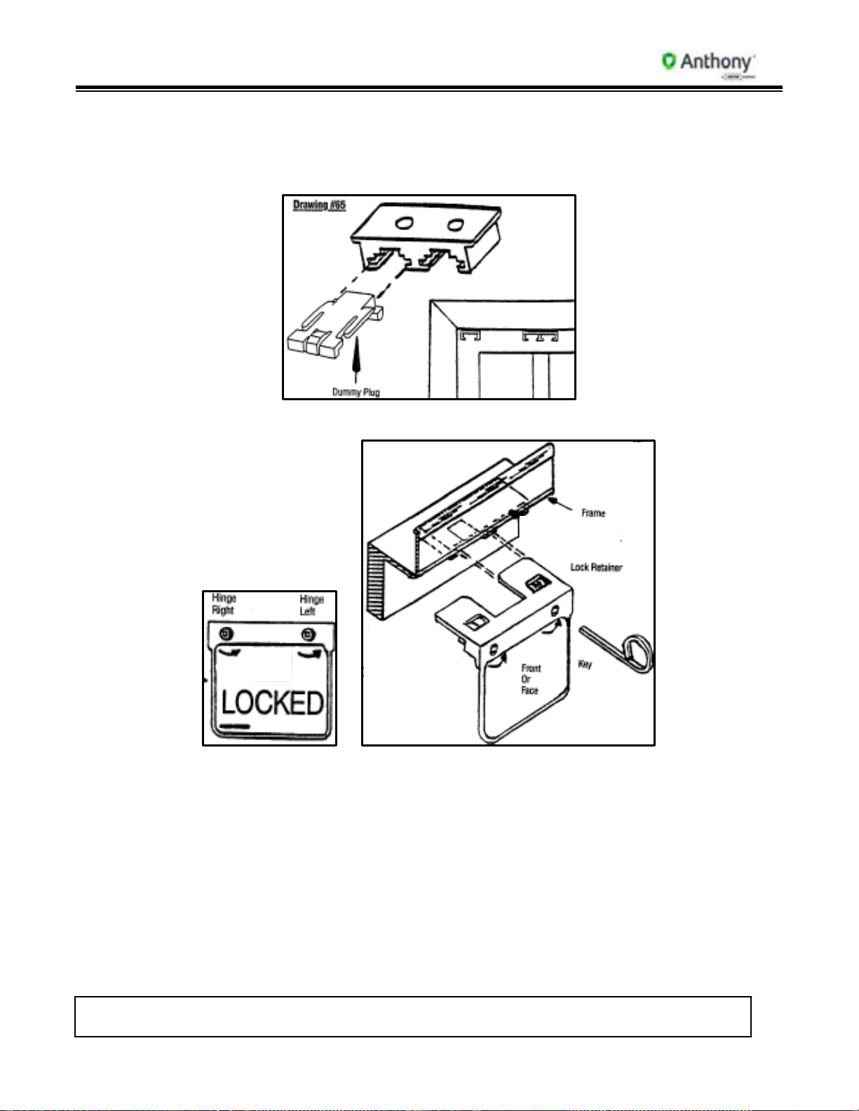
32. P.O.M. Lock Installation
1. Remove dummy plug from hinge pin access plate on top of frame on handle side of
door.
2. The P.O.M Lock inserts into a hinge pin access plate.
3. Insert key into P.O.M Lock’s square keyhole and turn key counterclockwise to lock.
4. Remove key.
5. To remove P.O.M. Lock, insert key into square hole and turn key clockwise.
6. Pull straight out to remove lock.
7. Replace dummy plug.
8. Lock only side that inserts into hinge access plate.
9. Facing doors, the lock on the right side is for left-hinged doors and the lock on the left
side is for right-hinged doors.

Model 101/2100 Doors Service & Installation
TITLE:
99-13312-S001 Model 101/2100 Doors Service &
Installation
REV.
B
Page 31 of 95
10. The P.O.M. Lock is manufactured to install in frame on top of handle rail side of door.
11. For retrofitting the P.O.M. Lock on existing doors in the field, contact Anthony
Customer Service or the local Sales Representative for information and instructions.
33. P.O.M. Lock Installation
1. To install the retrofit retainer, measure in 1-1/2” from the edge of door (handle side) and
mark frame above the door.
2. Place template provided on frame, with the right edge of the template on the mark
previously made on the frame.
3. Mark the frame through the five (5) holes on the template with a pencil. Remove
template and center punch the marks on the frame.
4. Drill the four (4) outboard holes with an 11/64” drill, the center hole with a 5/8” drill and
deburr holes.
5. Place retrofit retainer bracket over the holes with the rectangular notch out. Use #10-32
x 5/16” screws provided and mount retainer bracket to frame.

Model 101/2100 Doors Service & Installation
TITLE:
99-13312-S001 Model 101/2100 Doors Service &
Installation
REV.
B
Page 32 of 95
6. Insert P.O.M. Lock into access plate and turn key to lock.
7. Remove key.
8. To remove P.O.M. Lock, insert key into square lock hole and turn the key clockwise.
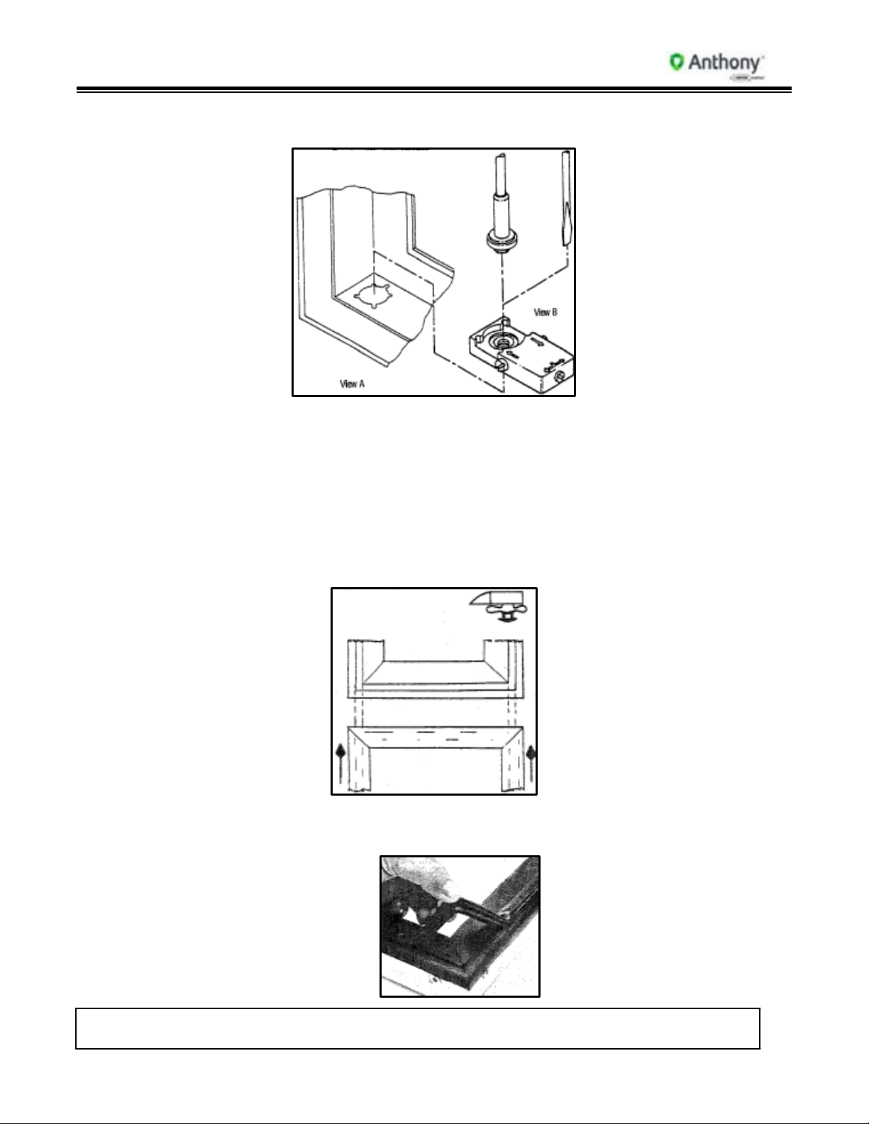
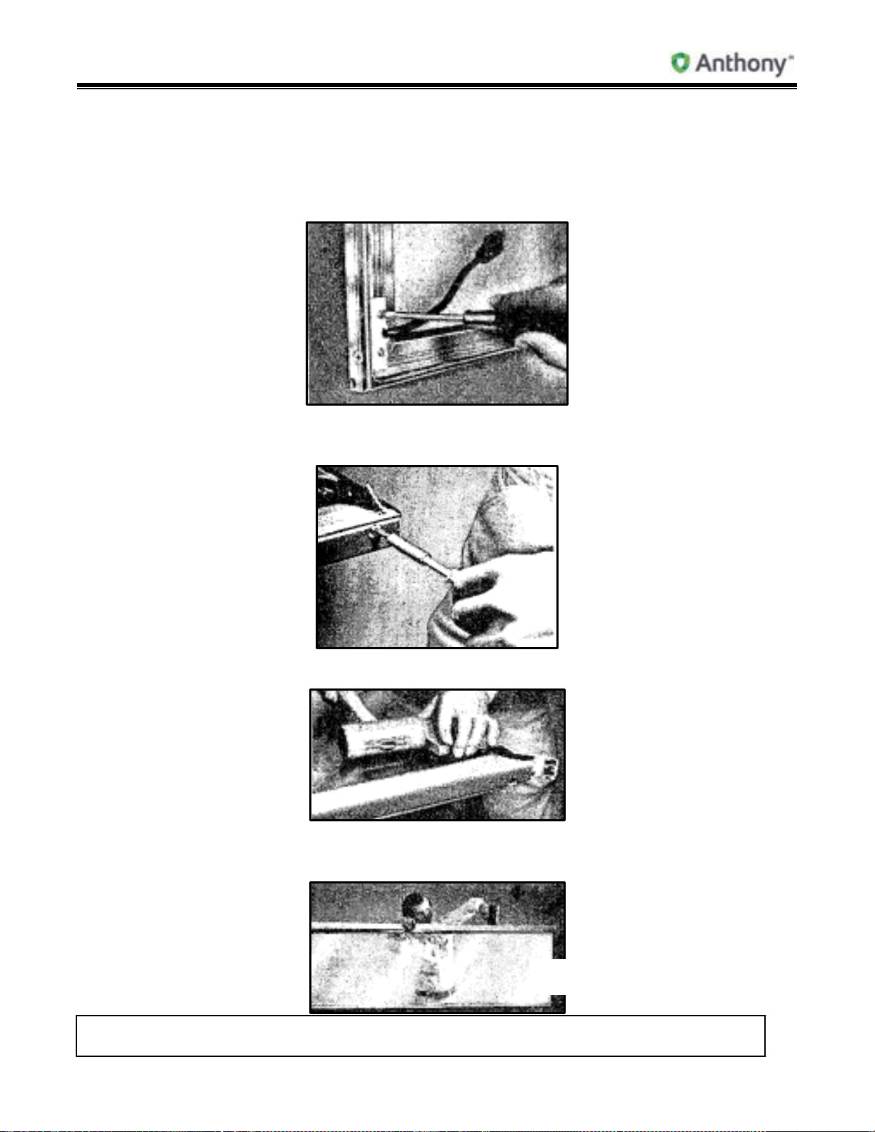
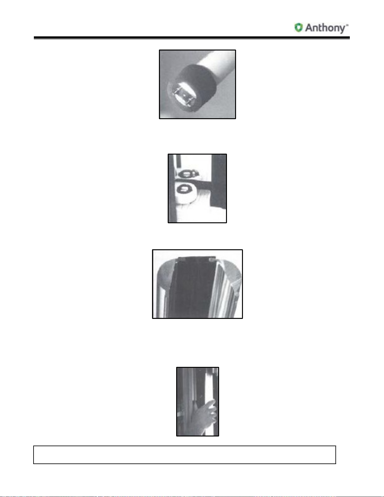
34. Model 101 Glass Replacement (Reglazing)
1. To remove torque rod from door, drive tapered shaft of torque rod from door.
2. Starting at corner of door, remove gasket and plastic from all four sides of door.
Model 101/2100 Doors Service & Installation
TITLE:
99-13312-S001 Model 101/2100 Doors Service &
Installation
REV.
B
Page 33 of 95
3. For models prior to 1987, unscrew SJ cord retainer to expose heating element wires.
For models after 1987, remove top or center access plate. Unsnap hinge pin from
female socket and remove, or unplug hinge pin lead wires to remove hinge pin. If
heated glass is used, cut Black and White lead wires to glass. Remove heating element
from door.
4. Using a square-head or clutch-head driver, remove screws on both side rails only.
Remove top and bottom door rails first.
5. Drive rails from glass, using mallet and block, always starting at corner of door.
6. Once rails have been removed from glass, re-insert new friction-fit glazing channel on
new glass and drive rails onto glass.

Model 101/2100 Doors Service & Installation
TITLE:
99-13312-S001 Model 101/2100 Doors Service &
Installation
REV.
B
Page 34 of 95
7. After both long rails have been affixed to glass, re-insert friction-fit glazing channel on
top and bottom and tighten miters with square-head or clutch-head driver.
Glazing
Channel
Square
Head
Screw
Clutch
Head
Screw
8. Once all four (4) door rails have been affixed to glass, measure diagonally to make sure
door is in square.
9. After replacing the glass unit, and when door rails are in square, re-insert heating
element wires in door rail channels and repeat process. Replace gasket and retainer
strips.
To re-install torque rod, align torque shaft with key way in door and drive tapered shaft
flush with bottom of door rail.
Note: If heated glass is used, when disassembling door, cut Black and White lead wires
to glass. When rebuilding door, pull glass heater leads out through heater access
hole before assembling top or side door rails. Re-connect Black and White lead
wires to heater wire Black and White lead wires. On newer models, re-connect
hinge pin to heater receptacle or heater lead wires.
10. When replacing heated glass, bus bars on glass (colored bars on top and bottom of
glass or up and down the sides) must go to the front of door, or customer side. This is
the heated side.
11. For questions about glass replacement, call Anthony’s Customer Service or local
Sales Representative.

Model 101/2100 Doors Service & Installation
TITLE:
99-13312-S001 Model 101/2100 Doors Service &
Installation
REV.
B
Page 35 of 95
35. Ordering Replacement Frames
1. Specify outside tip-to-tip dimensions of frame. Measure to nearest 1/16”.
2. Specify date of original manufacture and/or Anthony confirmation/invoice number.
3. Specify Cooler or Freezer.
4. Specify door size (width and height).
5. Specify finish (smooth/serrated/gold/silver/black, etc.).
6. Specify Model number.
7. Specify left or right hinge swing.
8. With or without heaters?
9. With or without lights?
10. With or without locks?
11. Specify any custom items on original order.
Replacement Frames (All Swing Doors)

Model 101/2100 Doors Service & Installation
TITLE:
99-13312-S001 Model 101/2100 Doors Service &
Installation
REV.
B
Page 36 of 95
36. Frame Heater Wire Replacement
1. Remove door from frame, following previous instructions for door removal.
2. Insert small flat-head screwdriver under back side edge of contact plate retainer and lift
up to remove.
Mullion Front
and Retainer
3. Remove contact plate to expose heater wires.
4. See following page for frame heater schematics.
5. Cut heater at the lead wire and pull heater out of track.

Model 101/2100 Doors Service & Installation
TITLE:
99-13312-S001 Model 101/2100 Doors Service &
Installation
REV.
B
Page 37 of 95
6. When ordering replacement heaters, specify which heater needs replacing: top, bottom,
end or center mullion heater. This varies depending upon the particular frame make-up..
7. Reverse instructions to re-install heater.
37. Models 101 & 2100 Frame Heater Schematic/Low Temp
Heater Wire Layout:
3-Door Frame (Typical for 2 Thru 5 Doors)
Bottom and End – Perimeter –
Center Top Supplement – Bottom Supplement.
Note: Top Heater to be installed before door sockets are set in place.
38. Models 101 & 2100 Frame Heater Schematic/Normal Temp
Heater Wire Layout:
3-Door Frame (Typical for 2 Thru 5 Doors)
Bottom and End – Perimeter and Center

Model 101/2100 Doors Service & Installation
TITLE:
99-13312-S001 Model 101/2100 Doors Service &
Installation
REV.
B
Page 38 of 95
39. Humastat Installation Procedure
1. Install Humastat Power Junction Box before refrigerator door power wiring, on the inside
wall of refrigerator.
2. Remove wiring compartment covers by removing four (4) sheet metal screws.
3. Connect heater hot wire to Red wire from control unit.
4. Connect input power hot wire to Black wire from control unit.
5. Connect all White wires, including common side of power line, line load and control unit
White wire.
6. Connect Green Ground wire from control unit to Green Ground wire at frame and to
incoming Ground wire (if furnished).
7. Replace the Wiring Compartment Cover with the sheet metal removed in No. 2 above.

Model 101/2100 Doors Service & Installation
TITLE:
99-13312-S001 Model 101/2100 Doors Service &
Installation
REV.
B
Page 39 of 95
8. Install Humastat Sensor on the outside wall of refrigerator above the door frame, within
three feet of power junction box.
120 VAC 50/60 Hz, 20 Amperes Maximum
a. Drill a 1/4” diameter hole through refrigerator wall directly above the door frame.
b. Use the wood probe supplied with the sensor to feed the sensor wire through the
refrigerator wall.
c. Apply permagum to back of sensor around the wire. Pull the wire through the hole
until the sensor makes close contact with the wall and secure it to the wall with the
9. Remove wood probe from sensor connector by holding the body of connector securely
10. Insert the sensor plug into the sensor jack on the outside end of the power junction
11. Set the heater control knob for the lowest value which keeps the door free of
screws provided Seal the probe wire with the permagum on inside of wall.
and pulling off the probe.
box.
undesirable moisture.

Model 101/2100 Doors Service & Installation
TITLE:
99-13312-S001 Model 101/2100 Doors Service &
Installation
REV.
B
Page 40 of 95
12. Red light indicates when heaters are functioning.
Control Panel End
Switch shall remain in Position “A” for normal operation
View
40. Model 101 Humastat
1. Sensor is prewired in frame mullion.
2. For Low Temp applications, see Sensor Part #F-161.
3. For Normal Temperature applications, see Sensor Part #F-1649.
41. Model 101 & 2100 Shelf Assembly Catalog Size/Shelf Size

Model 101/2100 Doors Service & Installation
TITLE:
99-13312-S001 Model 101/2100 Doors Service &
Installation
REV.
B
Page 41 of 95
Shelf Tabulation
Catalog Size
Shelf Size
24”
23 5/16” x 27”
30”
29 13/16” x 27”
NOTE:
For 24” 1- and 2-Door
Frames, use shelf
size 22 9/16” x 27”
26” 26 5/16” x 27”
For 3 Doors or more,
use 23 5/16” x 27”
"""
TITlE:
99-13312-8001Mode
101/2100
Doors
Ser..tce &
hstallation
B
Page 42of
95
=-,
>
,,.,,
1
21
•
• <
O Anth
ony·
42. Models 101 & 21
i -i;
.,..,i
oo
Frame &
i
I
5r
Qr
, '/
J
I
._::-r
.
F
shelving
l
_J
==i
.
-'
with Standard
($
M"
!. l
.
J\,
.
M
I I\
J
•
••
':)
Lighting
j
1"'1
<
I
.
••
ti
J
j
., {
'
!' l
!
s
f-
f-
;
•
<
;;
-
•
.

TITlE:
43. Models 101 & 21
oo
Frame &
shelving
with "ELS"
•'
O Anthony·
Electronic
Lighting
'
1---lf-
• fi
1-
-
-t-1--
-
-
·-
-
-'
--
--1
-1

"""
TITlE:
99-13312-8001Mode
101/2100
Doors
Ser..tce &
hstallation
B
Page 42of
95
99-13312-8001Mode
101/2100 Doors Ser..tce &
hstallation
"B""
Page 43of
95


Model 101/2100 Doors Service & Installation
TITLE:
99-13312-S001 Model 101/2100 Doors Service &
Installation
REV.
B
Page 44 of 95
44. Four-Post Stabilizer Bar Installation
1. The four-post stabilizer is designed to help support the posts during installation and
stabilize the system while in use.
2. Insert the forked end of stabilizer bar into the elongated holes in post.
3. Install the post stabilizers on the top and bottom of all posts, front to rear, before
installing shelves.
45. Four-Post Shelf System Installation
1. Attach post to inside frame by inserting post key into frame retaining bracket.
2. Before installing shelves, adjust all front posts to equal heights with leg leveling bolts at
bottom of posts.
.

Model 101/2100 Doors Service & Installation
TITLE:
99-13312-S001 Model 101/2100 Doors Service &
Installation
REV.
B
Page 45 of 95
3. Insert front of shelf in front post at angle as shown, then position rear shelf posts.
4. Drop rear of shelf down and pull back in slot on rear posts. Continue to add shelves
behind each door, spacing for desired product merchandising.
5. After installing shelves, adjust rear post leveling bolts to level. The Four-Post Shelf
System is now ready for merchandising.

Model 101/2100 Doors Service & Installation
TITLE:
99-13312-S001 Model 101/2100 Doors Service &
Installation
REV.
B
Page 46 of 95
46. Plastic Tag Molding Installation
1. Tag molding is the exact length of the shelf’s upper front bar. Center tag molding on
front of shelf. Hook bottom of tag molding under shelf across entire width of shelf.
Spread thumbs across tag molding and push up.
2. Snap top corner of tag molding strip onto shelf front. Apply even pressure across top of
tag molding as it is fed onto top horizontal bar on shelf front.
3. For replacement tag molding, specify width of shelf when ordering.

Model 101/2100 Doors Service & Installation
TITLE:
99-13312-S001 Model 101/2100 Doors Service &
Installation
REV.
B
Page 47 of 95
47. Model 2100 G.F.I. Location & Wiring Diagram
48. Lamp Replacement
1. Lift lamp up into top plunger socket, then out at bottom to remove.
2. Pull end caps off end of light shield, then remove bulb from shield.
3. To replace bulb, insert new bulb into lamp shield and snap in end caps. To replace
lamp, lift bulb up into top plunger socket, then set into bottom socket. Do not install
lamps without lamp shield.

Model 101/2100 Doors Service & Installation
TITLE:
99-13312-S001 Model 101/2100 Doors Service &
Installation
REV.
B
Page 48 of 95
49. Lamp Socket Replacement
1. To replace sockets, remove lamp, then pull top socket down and pull out of “D” hole. To
replace bottom socket, pull socket up and out of “D” hole. Extra lead wire is left in the
mullion for easy replacement.
2. Pull sockets out, then cut lead wires.
3. Reverse instructions to replace.
4. To re-install sockets, insert top front metal tab into “D” hole and snap socket up. For
bottom socket, insert metal tab into “D” hole and snap socket down to install.
5. Replace lamps.
6. For safety and efficiency, lamps should never be installed without shields.

Model 101/2100 Doors Service & Installation
TITLE:
99-13312-S001 Model 101/2100 Doors Service &
Installation
REV.
B
Page 49 of 95
50. Recessed Light Socket Replacement
1. Remove safety clips and light guard.
2. To remove top socket (plunger socket), pull socket down then out.
3. To remove bottom socket, pull up then out.
4. Mullion contains excess socket lead wire. Cut lead wires to sockets.
5. Re-wire new socket in place.
6. To re-install sockets, reverse above instructions.
7. Replace bulbs and lamp guards.
51. Recessed Lamp Channel Replacement with Remote Ballast
1. Insert flat-head screwdriver under back edge of light channel retainer to remove.
2. To replace, lay light channel into mullion, then snap on retainer as shown.

Model 101/2100 Doors Service & Installation
TITLE:
99-13312-S001 Model 101/2100 Doors Service &
Installation
REV.
B
Page 50 of 95
52. Recessed Lamp Guard Replacement with Remote Ballast
1. Compress metal safety clips on each end and in the center of light guard to remove.
2. Lift light guard up to release from lower shield clip, drop down to release guard from top
clip.
3. To replace, insert guard into bottom clip first, then into top clip. Compress metal safety
clips when they’re put into recessed channel. Release to let clip seat into groove in
recessed channel.
4. To replace end plastic clips, compress sides and pull out.
5. To replace end clips, compress new end clip and insert into access groove in light
channel.
53. Recessed Lamp Replacement
1. Remove light guard per previous instructions.
2. Lift bulb up into top plunger socket and pull bulb out and down at bottom to remove.
3. To replace bulb, insert bulb into top light socket and set into bottom socket.
4. Re-install light guard and clips.
54. “Boost & Buck” Transformer Wiring Diagram
1. Recommended wiring for 110/120 volt applications.
Model 101/2100 Doors Service & Installation
TITLE:
99-13312-S001 Model 101/2100 Doors Service &
Installation
REV.
B
Page 51 of 95
2. Transformer, wired as follows, will increase the 115 volt line voltage by 10% and the
applied heat by 20%.
3. Hot to H1-X3.
4. Neutral to H2-X1-X3.
5. Load for heaters X2-X4.
6. Transformer is rated for an 18 Amp load.
55. Frame Junction Box Wiring (Standard Production)
1. Remove cover.
2. Wires are marked as to application.
1-Black for frame heat.
1-Red for door heat.
1-White, common for Black and Red.
1-Blue for lights.
1-Blue/White common for lights.
1-Green/Yellow for ground.
56. Models 101 & 2100 Light Fixture Placement (Prior to 10/93)
Pre-wired lighting uses only 1-light ballasts. Non pre-wired uses 1- or 2-light ballasts.
Frame Breakdown – Each Frame Section with Full Flange

Model 101/2100 Doors Service & Installation
TITLE:
99-13312-S001 Model 101/2100 Doors Service &
Installation
REV.
B
Page 52 of 95
= Light
X = No Light
D = Wood Divider
Example: 6-Door Lineup (2 sets of 3) of Model 101 or 2100 with Full
Flange
57. Models 101 & 2100 Light Fixture Placement – “Continuous” Lineup
(10/93 to Present)
Pre-wired lighting using 1- or 2-light ballasts. Continuous lineup with “E.L.S.” lighting.
= Light
Frame breakdown: 1 set of 6 (2 sets of 3, joined with sex bolts).
Note: Lamp at each end of frame and on each mullion.
Pre-wired lighting using 1-light ballasts. Continuous lineup with standard lighting.
Frame breakdown: 1 set of 6 (2 sets of 3, joined with sex bolts).
Note: One more lamp than number of doors.

58. Models 101
& 2100 Low Temp 120-Volt Remote Ballast and
Wiring
HMPiallasl
Diagram tor
!llK
'
/IKf
BUE
BWE
UNI\Itf$i.L t'95lS·.TC-P
1-Light Systems
RED
RE:J
Kll..K\
15:»2
O Anthony·
Lamp

Model 101/2100 Doors Service & Installation
TITLE:
99-13312-S001 Model 101/2100 Doors Service &
Installation
REV.
B
Page 54 of 95
"""
99-13312-8001Mode
TITlE:
101/2100 Doors Ser..tce &
hstallation
Page 53of
B
95

TITLE:
99-13312-S001 Model 101/2100 Doors Service &
Installation
REV.
B
Page 55 of 95
=
59. Models 101 & 2100 Low Temp 120-Volt Remote Ballast and
>O
T
Wiring
Diagram tor
2-Light Systems
2-Lamp
83118$1
.t811
j
F60110CIINH0{6)"
F'?Z110CNNHO
vc:uow
0CIJNWO{>Iil
(7?"}
}
O
Anthony·
Lamp
KU.
KA*530-2
lJ
IL

TITlE:
99-13312-8001Mode
101/2100
Doors
Ser..tce &
hstallation
Page of
"B""
54 95

TITLE:
99-13312-S001 Model 101/2100 Doors Service &
Installation
REV.
B
Page 57 of 95
Model 101/2100 Doors Service & Installation
60. Models 101 & 2100 Normal Temp 120-Volt Remote Ballast and Lamp
Wiring Diagram for 1- & 2-Light Systems
Lighting Diagram for 1- & 2-Light
Ballast
61. Models 101 & 2100 Normal Temp 120-Volt Remote Ballast and Lamp
Wiring Diagram for 3-Light Systems
Lighting Diagram for 3-Light Ballast

Model 101/2100 Doors Service & Installation
TITLE:
99-13312-S001 Model 101/2100 Doors Service &
Installation
REV.
B
Page 56 of 95
62. Normal Temp & Low Temp 120-Volt Ballast and Lamp Wiring Diagram -
Pre-Wired 1-Light System
Wiring:
1. Ballast has two (2) Red wires, two (2) Blue wires, a Black and a White wire.
a. Wire two (2) Red wires to two (2) Red wires on bottom socket.
b. Wire two (2) Blue wires to two (2) Blue wires on top socket.
c. Black wire goes to hot, White wire goes to neutral.
63. Ballast Replacement
1. For replacement ballast, always use ballast number from existing ballast.
2. Remove door from frame opening.

Model 101/2100 Doors Service & Installation
TITLE:
99-13312-S001 Model 101/2100 Doors Service &
Installation
REV.
B
Page 57 of 95
3. Insert flat-head screwdriver under back edge of contact plate retainer to remove.
4. Remove contact plate from mullion.
5. Pull heat barrier from mullion to remove.
6. The ballast has a wiring diagram on its face. To replace ballast, cut lead wires: 2-Red,
2-Blue, 1-Black and 1-White.
7. Follow color codes to rewire ballast. Reverse instructions to replace heat barrier,
contact plate and contact plate retainer.
Note: When the two (2) Blue and two (2) Red wires are connected to the top and
bottom sockets, make sure the wiring is one-to-one. Do not gang wire.
64. “ELS” Lamp Socket Replacement
WARNING: Before servicing Anthony doors make sure all power to case is off. Always
1. Remove front contact plate retainer.
2. Remove contact plate.
use a qualified electrician.

Model 101/2100 Doors Service & Installation
TITLE:
99-13312-S001 Model 101/2100 Doors Service &
Installation
REV.
B
Page 58 of 95
3. Remove top and bottom spring steel clips. Insert small flat-head screwdriver under clip
to release clip from side of fixture. On one side at a time, pull clip out of pre-punched
holes in side of mullion.
4. Gently pull clips away from fixture and set clips aside for re-installation.
5. Remove “ELS” lens. Starting at the top, pull lens away from front of light fixture, next
to frame mullion. (If necessary, a small flat-head screwdriver can be inserted between
lens and back mullion plastic to ease lens out of groove.) There is no need to remove
lens from the bridge. (The “bridge” is the black or clear plastic piece connecting the
two lenses at the back of the fixture.)
6. Remove bulb.
7. From the front of the socket, depress both sides of socket and push socket out through
front of mullion.
8. Cut ballast lead wires to socket as close to socket as possible.
9. To replace a socket, insert socket into access hole in mullion and push until tabs on
side of socket snap in place on back side of mullion.
10. Insert ballast lead wires into socket connections.
11. Re-install bulb, lens and front contact plate.

Model 101/2100 Doors Service & Installation
TITLE:
99-13312-S001 Model 101/2100 Doors Service &
Installation
REV.
B
Page 59 of 95
65. “ELS” Electronic Ballast Replacement and Wiring Instructions
WARNING: Before servicing Anthony doors make sure all power to case is off. Always
1. Refer to drawings on following pages for ballast location and wiring.
2. Remove door that hinges on mullion where ballast will be replaced.
3. From front of frame, remove contact plate and retainer by inserting a flat-head
screwdriver under back edge of black contact plate retainer, and gently pull to unsnap
retainer from mullion. Repeat from other side of mullion and remove contact plate.
4. With ballast now exposed, remove screw on top end of ballast. Slide ballast up and out
of punched mullion tabs.
5. Disconnect or cut all lead wires. If cut, leave enough lead wire to re-connect new ballast
with wire nut.
6. Insert bottom of new ballast in punched tabs on mullion. Re-install top screw in top end
of ballast.
use a qualified electrician.

Model 101/2100 Doors Service & Installation
TITLE:
99-13312-S001 Model 101/2100 Doors Service &
Installation
REV.
B
Page 60 of 95
7. Re-connect new ballast lead wires using the following Wiring Diagrams:
2-Light (1-Door)
3-Light (2-Door)
4-Light (3-Door)
5-Light (4-Door)
6-Light (5-Door)
8. Lay contact plate flat on mullion. Staring at the top, insert contact plate retainer into front
edge of mullion. Snap retainer on back edge of mullion. Repeat instructions for opposite
side.
120V Electronic Ballast Wiring Diagrams

Model 101/2100 Doors Service & Installation
TITLE:
99-13312-S001 Model 101/2100 Doors Service &
Installation
REV.
B
Page 61 of 95
120V ELS Lighting System Component Layout
1-Door Section 2-Door Section
3-Door
Section

Model 101/2100 Doors Service & Installation
TITLE:
99-13312-S001 Model 101/2100 Doors Service &
Installation
REV.
B
Page 62 of 95
220V Electronic Ballast Wiring Diagrams
4-Door
5-Door
Section
Section

Model 101/2100 Doors Service & Installation
TITLE:
99-13312-S001 Model 101/2100 Doors Service &
Installation
REV.
B
Page 63 of 95

Model 101/2100 Doors Service & Installation
TITLE:
99-13312-S001 Model 101/2100 Doors Service &
Installation
REV.
B
Page 64 of 95
220V ELS Lighting System Component Layout
1-Door Section 2-Door Section
3-Door
4-Door
Section
Section

Model 101/2100 Doors Service & Installation
TITLE:
99-13312-S001 Model 101/2100 Doors Service &
Installation
REV.
B
Page 65 of 95
5-Door
Section
66. T-8 Lamp Replacement Instructions
CENTER MULLION FIXTURES
1. Turn light power off before start of lamp replacement.
2. Remove top and bottom spring steel clips. Insert small flat-head screwdriver under
clip to release clip from side of fixture (as shown in the following figure). On one side at
a time, pull clip out of pre-punched holes in side of mullion.

Model 101/2100 Doors Service & Installation
TITLE:
99-13312-S001 Model 101/2100 Doors Service &
Installation
REV.
B
Page 66 of 95
3. Remove ELS lens. Starting at top, pull lens away from front of light fixture that is
attached to the frame mullion. If necessary, a small flat-head screwdriver can be
inserted between the lens and black mullion plastic, to ease the lens out of the groove.
There is no need to remove the lens from the bridge (the black or clear plastic piece
connecting the two lenses at the back of the fixture).
If pulled away from one side carefully, the lens will swing back into the case to give
access to the bulb. Otherwise, the left and right lenses and the bridge will pull away
from the fixture – in one complete section.
4. With the lens removed, hold lamp with fingers and twist bulb to line up with socket
access holes.
Remove old bulb. Remove insulator tubes from both ends of old bulb and replace on
ends of new bulb.
Model 101/2100 Doors Service & Installation
TITLE:
99-13312-S001 Model 101/2100 Doors Service &
Installation
REV.
B
Page 67 of 95
To install new bulb, place into socket and turn two clicks. There are foam end caps
on the top and bottom of lamp sockets. End caps must be attached before lens is
replaced.
5. Be sure that both ELS lenses are snapped securely into the plastic bridge before re-
installing on the light fixture.
6. Install clip on plastic bridge, if required, before re-installing on light fixture.
7. Starting at the top on one side of the light fixture, line up the edge of the lens with the
groove in the fixture plastic. Snap lens into groove. Repeat with lens on the other side,
if removed.

Model 101/2100 Doors Service & Installation
TITLE:
99-13312-S001 Model 101/2100 Doors Service &
Installation
REV.
B
Page 68 of 95
8. Holding lens snugly against top of light fixture, install spring steel clip over lenses. Snap
clip into pre-punched holes on each side of mullion. Move to bottom of fixture and install
bottom clip.
IMPORTANT: Bulb insulators must be on each end of bulb before lenses are re-installed.
Foam end caps should be securely attached to top and bottom of lamp
sockets. (Foam end caps are cut to fit snugly, but if they have become
dislodged, or pulled out during changes, they must be replaced!)
9. Turn light power on.
FRAME END FIXTURES
1. Turn light power off before start of lamp replacement.
2. Remove top and bottom spring steel clips. Insert small flat-head screwdriver under
flat portion of spring steel clip to remove from side of fixture (as shown in the following
figure). Swing clips to the side until re-installation.

Model 101/2100 Doors Service & Installation
TITLE:
99-13312-S001 Model 101/2100 Doors Service &
Installation
REV.
B
Page 69 of 95
3. Remove ELS lens. Starting at top, pull lens away from inside front edge of fixture. If
necessary, a small flat-head screwdriver can be inserted between the lens and black
fixture plastic, to ease the lens out of the groove. If rear edge of lens is left in fixture
plastic, lens will swing back on flexible “hinge” to expose bulb.
4. Reaching into fixture, hold bulb with fingers and twist to line up with socket access
holes. Remove old bulb. Remove insulator tubes from both ends of old bulb and
replace on ends of new bulb.
To install new bulb, place into socket and turn two clicks. There are foam end caps
on the top and bottom of lamp sockets. End caps must be attached before lens is
replaced.

Model 101/2100 Doors Service & Installation
TITLE:
99-13312-S001 Model 101/2100 Doors Service &
Installation
REV.
B
Page 70 of 95
5. Re-install ELS lens. If lens has been completely removed from fixture, pull grooved
plastic rear section of fixture forward, and snap rear edge of ELS Lens back into the
groove. (This part of the light fixture has a “hinge” or flexible portion, that swings away
for easy bulb access. Install clip on hinging side, if required, before re-installing the
other end of the lens. Starting at the top, snap the other side of the lens into the front
groove of the lamp fixture.
6. End clips conform to the shape of the end fixture, and can be snapped into place only
one way. The curved sides of the spring steel clip should be touching the lens. Snap
the top and bottom clips into place.
IMPORTANT: Bulb insulators must be on each end of bulb before lens is re-installed.
Foam end caps should be securely attached to top and bottom of lamp
sockets. (Foam end caps are cut to fit snugly, but if they have become
dislodged, or pulled out during changes, they must be replaced!)
7. Turn light power on.

Model 101/2100 Doors Service & Installation
TITLE:
99-13312-S001 Model 101/2100 Doors Service &
Installation
REV.
B
Page 71 of 95
CASE TEMPERATURE
(F)
40 35 30 25 20
70 70 66 61 58 53 75 67 62 59 55 52 80 63 60 57 53 50 85 60 58 53 50 49 90 58 55 52 49 47
70 74 71 68 65 62 75 72 68 66 63 60 80 68 66 63 60 58 85 66 64 61 58 56 90 65 62 59 57 54
70 76 75 70 67 63 75 75 70 69 66 62 80 70 68 66 62 59 85 68 66 63 60 58 90 67 64 60 58 56
70 98 92 90 84 80 75 95 90 86 84 77 80 90 85 81 76 73 85 86 80 78 72 69 90 82 78 74 70 66
% REL HUMIDITY @ WHICH CONDENSATION FORMS ON GLASS
CASE TEMPERATURE
(F)
+5 0 -5
-10
-15
-20
-25
90
88
83
81
79
76
73
85
81
80
78
76
72
70
80
80
78
75
72
70
69
79
78
77
73
71
68
68
78
75
73
71
69
67
65
67. Dew Point Chart
GLASS
TYPE
TWO PANE
NHG*
THREE
PANE NHG*
REFLECTIVE
PANE
TWO
NHG*
PANE
TWO
HEATED
GLASS
*NHG = Non Heated Glass
GLASS
TYPE
ROOM TEMP
(F)
ROOM
TEMP (F)
NORMAL TEMPERATURE APPLICATIONS
LOW TEMPERATURE APPLICATIONS
THREE PANE
HEATED
REFLECTIVE
GLASS
% REL HUMIDITY @ WHICH CONDENSATION FORMS ON GLASS
Calculations make no allowance for air leaks or unusual air flow patterns within cases and are
intended to be used as guidelines only.

Model 101/2100 Doors Service & Installation
TITLE:
99-13312-S001 Model 101/2100 Doors Service &
Installation
REV.
B
Page 72 of 95
NUMBER OF DOORS:
1 2 3 4 5 6 7 8 9 10 STYLE:
APPLICATION:
24 x 36
24 x 67
24 x 75
26 x 67
26 x 75
28 x 75
28 x 79
30 x 36
30 x 67
30 x 75
30 x 79
LIGHT
24 x 36
11.79
12.78
13.93
14.92
15.99
17.04
18.11
19.26
20.25
21.32 NA
24 x 67
18.16
19.77
21.40
23.01
24.63
26.36
27.98
29.61
31.22
32.84
0.85
24 x 75
19.91
21.72
23.49
25.30
27.09
28.96
30.75
32.52
34.33
36.12
0.85
26 x 67
19.90
21.69
23.30
25.09
26.79
28.92
30.62
32.23
34.02
35.72
0.85
26 x 75
21.33
23.16
25.23
27.06
29.01
30.88
32.83
34.90
36.73
38.68
0.85
28 x 75
22.52
24.48
26.58
28.54
30.57
32.64
34.67
36.77
38.73
40.76
0.85
28 x 79
23.70
25.77
28.02
30.09
32.25
34.36
36.52
38.77
40.84
43.00
0.85
30 x 36
14.59
15.96
16.93
18.30
19.47
21.28
22.45
23.42
24.79
25.96 NA
30 x 67
21.36
23.34
24.94
26.92
28.71
31.12
32.91
34.51
36.49
38.28
0.85
30 x 75
23.18
25.23
27.18
29.23
31.23
33.64
35.64
37.59
39.64
41.64
0.85
30 x 79
24.46
26.70
28.62
30.86
32.94
35.60
37.68
39.60
41.84
43.92
0.85
68. Electrical Information for Model 101 Low Temp Heated Doors, Frames
& Standard Light Fixtures
18
19
20
AMPS PER
Heater Amperages @ 120 Volts
Low temp doors with heaters, 3-Pane Heated Reflective Glass (5.75 W/SQ. FT.)
Case Temperature -10°F, Humidity 75% or less, @ 75°F ambient.
NOTES: 1. All amperages are design amperages subject to the following tolerances: heated glass +/- 8%.
2. Although the amperages are calculated at 120 volts, all doors are designed to operate without
sweating when used within the application parameters with a voltage range of +/- 10%.
3. When calculating standard lamp amperage, add 1 lamp to the number of doors in the line-up and
multiply that number by the appropriate AMPS PER LIGHT value.
4. Design parameters do not make allowances for factors such as air leaks or unusual air flow
patterns within cases; therefore, some sweating may occur when upper limits of temperature or
humidity are encountered.
11
12
1.12 2.20 3.27 4.26 5.33 6.54 7.53 8.52 9.59 10.66
1.86 3.40 4.98 6.59 8.21 9.96 11.57 13.18 14.80 16.42
2.00 3.68 5.43 7.24 9.03 10.86 12.67 14.48 16.27 18.06
1.91 3.74 5.44 7.23 8.93 10.88 12.67 14.46 16.16 17.86
2.13 4.05 5.89 7.72 9.67 11.78 13.61 15.44 17.39 19.34
2.18 4.15 6.20 8.16 10.19 12.40 14.36 16.32 18.35 20.38
2.41 4.39 6.52 8.59 10.75 13.04 15.11 17.18 19.34 21.50
1.34 2.68 3.95 5.32 6.49 7.90 9.27 10.64 11.81 12.98
2.10 3.98 5.80 7.78 9.57 11.60 13.58 15.56 17.35 19.14
2.27 4.32 6.36 8.41 10.41 12.72 14.77 16.82 18.82 20.82
2.42 4.56 6.66 8.90 10.98 13.32 15.56 17.80 19.88 21.96
13
14
15
16
17

Model 101/2100 Doors Service & Installation
TITLE:
99-13312-S001 Model 101/2100 Doors Service &
Installation
REV.
B
Page 73 of 95
NUMBER OF DOORS:
1 2 3 4 5 6 7 8 9 10 STYLE:
APPLICATION:
24 x 36
0.27
0.55
0.82
1.09
1.36
1.64
1.91
2.18
2.45
2.72
24 x 67
0.43
0.86
1.30
1.73
2.16
2.60
3.03
3.46
3.89
4.32
24 x 75
0.46
0.92
1.39
1.85
2.31
2.78
3.24
3.70
4.16
4.62
26 x 67
0.44
0.87
1.31
1.74
2.18
2.62
3.05
3.48
3.92
4.36
26 x 75
0.47
0.93
1.40
1.87
2.34
2.80
3.27
3.74
4.21
4.68
28 x 75
0.50
0.99
1.49
1.99
2.48
2.98
3.48
3.98
4.47
4.96
28 x 79
0.49
0.97
1.46
1.95
2.43
2.92
3.41
3.90
4.38
4.86
30 x 36
0.31
0.62
0.92
1.23
1.54
1.84
2.15
2.46
2.77
3.08
30 x 67
0.47
0.94
1.40
1.87
2.34
2.80
3.27
3.74
4.21
4.68
30 x 75
0.49
0.98
1.47
1.96
2.45
2.94
3.43
3.92
4.41
4.90
30 x 79
0.53
1.05
1.58
2.10
2.63
3.16
3.68
4.20
4.73
5.26
NUMBER OF DOORS:
1 2 3 4 5 6 7 8 9 10 STYLE:
APPLICATION:
24 x 36
0.45
0.91
1.36
1.82
2.27
2.72
3.18
3.64
4.09
4.54
24 x 67
0.70
1.39
2.09
2.78
3.48
4.18
4.87
5.56
6.26
6.96
24 x 75
0.76
1.52
2.28
3.05
3.81
4.56
5.33
6.10
6.86
7.62
26 x 67
0.71
1.43
2.14
2.85
3.57
4.28
4.99
5.70
6.42
7.14
26 x 75
0.81
1.61
2.42
3.23
4.03
4.84
5.65
6.46
7.26
8.06
28 x 75
0.82
1.64
2.47
3.30
4.12
4.94
5.77
6.60
7.42
8.24
28 x 79
0.86
1.72
2.58
3.45
4.30
5.16
6.03
6.90
7.75
8.60
30 x 36
0.52
1.04
1.56
2.08
2.61
3.12
3.64
4.16
4.69
5.22
30 x 67
0.77
1.54
2.32
3.09
3.86
4.64
5.41
6.18
6.05
7.72
30 x 75
0.81
1.62
2.44
3.25
4.06
4.88
5.69
6.50
7.31
8.12
30 x 79
0.85
1.70
2.55
3.40
4.25
5.10
5.95
6.80
7.65
8.50
69. Electrical Information for Model 101 Normal Temp Heated Doors,
Frames & Standard Light Fixtures
Heater Amperages @ 120 Volts
Normal temp doors with heaters, 2-Pane Non-Heated Glass
Case Temperature 38°F, Humidity 65% or less, @ 75°F ambient.
Normal temp doors with heaters, 3-Pane Non-Heated Glass or 2-Pane Reflective NHG
Case Temperature 33°F, Humidity 68% or less, @ 75°F ambient.

Model 101/2100 Doors Service & Installation
TITLE:
99-13312-S001 Model 101/2100 Doors Service &
Installation
REV.
B
Page 74 of 95
NUMBER OF DOORS:
1 2 3 4 5 6 7 8 9 10 STYLE: Normal temp doors with heaters, 2-Pane Heated Glass
APPLICATION: Case Temperature 31°
24 x 36
0.80
1.61
2.41
3.21
4.01
4.82
5.62
6.42
7.22
8.02
24 x 67
1.36
2.73
4.09
5.46
6.82
8.18
9.55
10.92
12.28
13.64
24 x 75
1.52
3.04
4.55
6.07
7.59
9.10
10.62
12.14
13.66
15.18
26 x 67
1.44
2.88
4.32
5.76
7.20
8.64
10.08
11.52
12.96
14.40
26 x 75
1.58
3.16
4.73
6.31
7.89
9.46
11.04
12.62
14.20
15.78
28 x 75
1.65
3.31
4.97
6.62
8.27
9.94
11.59
13.24
14.89
16.54
28 x 79
1.73
3.47
5.22
6.96
8.70
10.44
12.18
13.92
15.66
17.40
30 x 36
0.97
1.94
2.91
3.88
4.85
5.82
6.79
7.76
8.73
9.70
30 x 67
1.56
3.12
4.68
6.24
7.80
9.36
10.92
12.48
14.04
15.60
30 x 75
1.71
3.41
5.12
6.83
8.54
10.24
11.95
13.66
15.37
17.08
30 x 79
1.79
3.57
5.36
7.15
8.93
10.72
12.51
14.30
16.08
17.86
LIGHT
24 x 36
3.00
3.27
3.54
3.81
4.08
4.36
4.63
4.90
5.17
5.44
0.46
24 x 67
4.76
5.19
5.62
6.05
6.48
6.92
7.35
7.78
8.21
8.64
0.55
24 x 75
5.09
5.55
6.01
6.47
6.93
7.40
7.86
8.32
8.78
9.24
0.55
26 x 67
4.79
5.22
5.66
6.10
6.54
6.96
7.40
7.84
8.28
8.72
0.55
26 x 75
5.14
5.61
6.08
6.55
7.02
7.48
7.95
8.42
8.89
9.36
0.55
28 x 75
5.74
5.97
6.45
6.95
7.44
7.96
8.45
8.93
9.43
9.92
0.55
28 x 79
5.36
5.85
6.32
6.81
7.29
7.80
8.28
8.75
9.24
9.72
0.55
30 x 36
3.38
3.69
4.00
4.31
4.62
4.92
5.23
5.54
5.85
6.16
0.46
30 x 67
5.14
5.61
6.08
6.55
7.02
7.48
7.95
8.42
8.89
9.36
0.55
30 x 75
5.39
5.88
6.37
6.86
7.35
7.84
8.33
8.82
9.31
9.80
0.55
30 x 79
5.78
6.30
6.840
7.36
7.89
8.40
8.93
9.47
9.99
10.52
0.55
F, Humidity 80% or less, @ 75°F ambient.
NOTES: 1. All amperages are design amperages subject to the following tolerances: non-heated glass +/- 5%,
heated glass +/- 8%.
2. Although the amperages are calculated at 120 volts, all doors are designed to operate without
sweating when used within the application parameters with a voltage range of +/- 10%.
11
12
13
14
15
16
17
18
19
20
AMPS PER

Model 101/2100 Doors Service & Installation
TITLE:
99-13312-S001 Model 101/2100 Doors Service &
Installation
REV.
B
Page 75 of 95
AMPS PER
LIGHT
24 x 36
5.00
5.46
5.90
6.36
6.81
7.28
7.73
8.17
8.63
9.08
0.46
24 x 67
7.65
8.34
9.05
9.74
10.44
11.12
11.82
12.53
13.22
13.92
0.55
24 x 75
8.38
9.15
9.90
10.67
11.43
12.20
12.96
13.71
14.48
15.24
0.55
26 x 67
7.84
8.55
9.28
9.99
10.71
11.40
12.12
12.85
13.56
14.28
0.55
26 x 75
8.88
9.69
10.48
11.29
12.09
12.92
13.72
14.51
15.32
16.12
0.55
28 x 75
9.07
9.90
10.71
11.54
12.36
13.20
14.02
14.83
15.66
16.48
0.55
28 x 79
9.48
10.35
11.18
12.05
12.90
13.80
14.65
15.48
16.35
17.20
0.55
30 x 36
5.72
6.24
6.78
7.30
7.83
8.32
8.85
9.39
9.91
10.44
0.46
30 x 67
8.50
9.27
10.04
10.81
11.58
12.36
13.13
13.90
14.67
15.44
0.55
30 x 75
8.94
9.75
10.56
11.37
12.18
13.00
13.81
14.62
15.43
16.24
0.55
30 x 79
9.35
10.20
11.05
11.90
12.75
13.60
14.45
15.30
16.15
17.00
0.55
LIGHT
24 x 36
8.83
9.63
10.43
11.23
12.03
12.84
13.64
14.44
15.24
16.04
0.46
24 x 67
15.01
16.38
17.74
19.10
20.46
21.84
23.20
24.56
25.92
27.28
0.55
24 x 75
16.69
18.21
19.73
21.25
22.77
24.28
25.80
27.32
28.84
30.36
0.55
26 x 67
15.84
17.28
18.72
20.16
21.60
23.04
24.48
25.92
27.36
28.80
0.55
26 x 75
17.35
18.93
20.51
22.09
23.67
25.24
26.82
28.40
29.98
31.56
0.55
28 x 75
18.21
19.86
21.51
23.16
24.81
26.48
28.13
29.78
31.43
33.08
0.55
28 x 79
19.14
20.88
22.62
24.36
26.10
27.84
29.58
31.32
33.06
34.80
0.55
30 x 36
10.67
11.64
12.61
13.58
14.55
15.52
16.49
17.46
18.43
19.40
0.46
30 x 67
17.16
18.72
20.28
21.84
23.40
24.96
26.52
28.08
29.64
31.20
0.55
30 x 75
18.78
20.49
22.20
23.91
25.62
27.32
29.03
30.74
32.45
34.16
0.55
30 x 79
19.66
21.45
23.22
25.01
26.79
28.60
30.38
32.15
33.94
35.72
0.55
11
12
13
14
15
16
17
18
19
20
11
12
13
14
15
16
17
18
19
20
AMPS PER
NOTES: 3. When calculating standard lamp amperage, add 1 lamp to the number of doors in the line-up and
multiply that number by the appropriate AMPS PER LIGHT value.
4. Design parameters do not make allowances for factors such as air leaks or unusual air flow
patterns within cases; therefore, some sweating may occur when upper limits of temperature or
humidity are encountered.

Model 101/2100 Doors Service & Installation
TITLE:
99-13312-S001 Model 101/2100 Doors Service &
Installation
REV.
B
Page 76 of 95
MODEL 101 LOW
TEMPERATURE
(3-PANE HEATED REFLECTIVE GLASS – CASE TEMP -10°F)
DOOR SIZE
1 DOOR
2 DOOR
3 DOOR
4 DOOR
5 DOOR
NOTE:
MODEL 101 NORMAL TEMPERATURE
(2-PANE NON-HEATED GLASS – CASE TEMP 38°F)
DOOR SIZE
1 DOOR
2 DOOR
3 DOOR
4 DOOR
5 DOOR
24 x 36
586 948 1309
1670
2031
24 x 67
692 1159
1627
2094
2561
24 x 75
720 1214
1709
2203
2698
26 x 67
709 1194
1678
2162
2646
26 x 75
739 1252
1766
2279
2793
28 x 75
758 1290
1823
2355
2888
28 x 79
773 1321
1869
2417
2965
30 x 36
615 1006
1396
1787
2177
30 x 67
743 1262
1780
2299
2817
30 x 75
777 1328
1880
2431
2983
30 x 79
793 1361
1929
2497
3065
70. Heat Load in BTU/Hr for Model 101 Low Temp Glass, Door Rail,
Frame Heaters and Standard Lighting
(Per Door, with Doors Closed @ 75°F Store Ambient)
24 x 36
24 x 67
24 x 75
26 x 67
26 x 75
28 x 75
28 x 79
30 x 36
30 x 67
30 x 75
30 x 79
Add 10-20% to above values depending on door opening frequency.
874
1061
1112
1094
1145
1182
1207
932
1155
1212
1241
1448
1821
1924
1887
1990
2064
2113
1564
2009
2124
2183
2022
2582
2736
2681
2835
2946
3020
2196
2864
3036
3124
2596
3343
3548
3475
3680
3828
3927
2828
3718
3948
4065
71. Heat Load in BTU/Hr for Model 101 Normal Temp Glass, Door Rail,
Frame Heaters and Standard Lighting
(Per Door, with Doors Closed @ 75°F Store Ambient)
3170
4104
4360
4268
4525
4710
4834
3460
4573
4860
5006

Model 101/2100 Doors Service & Installation
TITLE:
99-13312-S001 Model 101/2100 Doors Service &
Installation
REV.
B
Page 77 of 95
MODEL 101 NORMAL TEMPERATURE
(3-PANE NON-HEATED GLASS OR 2-PANE REFL. NHG – CASE TEMP 33°F)
DOOR SIZE
1 DOOR
2 DOOR
3 DOOR
4 DOOR
5 DOOR
24 x 36
599 974 1348
1722
2097
24 x 67
708 1192
1675
2159
2642
24 x 75
737 1248
1760
2272
2783
26 x 67
725 1225
1724
2224
2724
26 x 75
755 1284
1814
2344
2873
28 x 75
773 1320
1868
2416
2964
28 x 79
789 1352
1916
2479
3043
30 x 36
628 1031
1435
1838
2241
30 x 67
757 1290
1822
2355
2887
30 x 75
791 1356
1922
2488
3054
30 x 79
807 1390
1972
2555
3137
MODEL 101 NORMAL TEMPERATURE
(2-PANE HEATED GLASS – CASE TEMP 31°F)
DOOR SIZE
1 DOOR
2 DOOR
3 DOOR
4 DOOR
5 DOOR
24 x 36
665 1106
1546
1987
2427
24 x 67
825 1426
2026
2627
3227
24 x 75
867 1509
2150
2792
3434
26 x 67
850 1475
2100
2724
3349
26 x 75
894 1563
2231
2900
3569
28 x 75
921 1617
2312
3008
3704
28 x 79
944 1663
2382
3101
3820
30 x 36
708 1191
1675
2158
2641
30 x 67
899 1572
2246
2919
3593
30 x 75
948 1671
2393
3116
3839
30 x 79
972 1720
2467
3214
3962
NOTE: Add 10-20% to above values depending on door opening frequency.

Model 101/2100 Doors Service & Installation
TITLE:
99-13312-S001 Model 101/2100 Doors Service &
Installation
REV.
B
Page 78 of 95
MODEL 2100 LOW
TEMPERATURE
(3-PANE HEATED REFLECTIVE GLASS – CASE TEMP -10°F)
DOOR SIZE
1 DOOR
2 DOOR
3 DOOR
4 DOOR
5 DOOR
NOTE:
72. Heat Load in BTU/Hr for Model 2100 Low Temp Glass, Door Rail,
Frame Heaters and Standard Lighting
(Per Door, with Doors Closed @ 75°F Store Ambient)
24 x 36
24 x 67
24 x 75
26 x 67
26 x 75
28 x 75
28 x 79
30 x 36
30 x 67
30 x 75
30 x 79
Add 10-20% to above values depending on door opening frequency.
884
1079
1133
1114
1167
1206
1232
944
1178
1238
1269
1468
1859
1966
1928
2035
2113
2164
1589
2055
2176
2237
1052
2638
2798
2741
2902
3019
3097
2233
2933
3114
3206
2636
3417
3631
3555
3770
3925
4029
2877
3811
4052
4174
3219
4196
4464
4369
4637
4832
4961
3522
4688
4990
5143

Model 101/2100 Doors Service & Installation
TITLE:
99-13312-S001 Model 101/2100 Doors Service &
Installation
REV.
B
Page 79 of 95
NUMBER OF DOORS:
1 2 3 4 5 6 7 8 9 10 STYLE:
APPLICATION:
24 x 36
1.11
2.19
3.24
4.23
5.29
6.48
7.47
8.46
9.52
10.58
24 x 67
1.84
3.37
4.94
6.54
8.14
9.88
11.48
13.08
14.68
16.28
24 x 75
1.98
3.65
5.38
7.18
8.95
10.76
12.56
14.36
16.13
17.90
26 x 67
1.97
3.71
5.40
7.17
8.86
10.80
12.57
14.34
16.03
17.72
26 x 75
2.12
3.97
5.77
7.58
9.38
11.54
13.35
15.16
16.96
18.76
28 x 75
2.16
4.11
6.15
8.08
10.06
12.30
14.23
16.16
18.14
20.12
28 x 79
2.33
4.23
6.28
8.28
10.30
12.56
14.56
16.56
18.58
20.60
30 x 36
1.30
2.60
3.82
5.15
6.28
7.64
8.97
10.30
11.43
12.56
30 x 67
2.07
3.91
5.69
7.63
9.39
11.38
13.32
15.26
17.02
18.78
30 x 75
2.23
4.23
6.23
8.24
10.19
12.46
14.47
16.48
18.43
20.38
30 x 79
2.37
4.46
6.51
8.70
10.74
13.02
15.21
17.40
19.44
21.48
LIGHT
24 x 36
11.70
12.69
13.82
14.81
15.87
16.92
17.98
19.11
20.10
21.16 NA
24 x 67
18.02
19.62
21.22
22.82
24.42
26.16
27.76
29.36
30.96
32.56
0.85
24 x 75
19.74
21.54
23.28
25.08
26.85
28.72
30.49
32.23
34.03
35.80
0.85
26 x 67
19.74
21.51
23.12
24.89
26.58
28.68
30.37
31.98
33.75
35.44
0.85
26 x 75
20.93
22.74
24.53
26.34
28.14
30.32
32.12
33.91
35.72
37.52
0.85
28 x 75
22.31
24.24
26.27
28.20
30.18
32.32
34.30
36.33
38.26
40.24
0.85
28 x 79
22.84
24.84
26.88
28.88
30.90
33.12
35.14
37.18
39.18
41.20
0.85
30 x 36
14.12
15.45
16.38
17.71
18.84
20.60
21.73
22.66
23.99
25.12 NA
30 x 67
20.95
22.89
24.47
26.41
28.17
30.52
32.28
33.86
35.80
37.56
0.85
30 x 75
22.71
24.72
26.61
28.62
30.57
32.96
34.91
36.80
38.81
40.76
0.85
30 x 79
23.91
26.10
27.99
30.18
32.22
34.80
36.84
38.73
40.92
42.96
0.85
73. Electrical Information for Model 2100 Low Temp Heated Doors,
Frames & Standard Light Fixtures
18
19
20
Heater Amperages @ 120 Volts
Low temp doors with heaters, 3-Pane Heated Reflective Glass (5.75 W/SQ. FT.)
Case Temperature -10°F, Humidity 74% or less, @ 75°F ambient.
NOTES: 1. All amperages are design amperages subject to the following tolerances: heated glass +/- 8%.
2. Although the amperages are calculated at 120 volts, all doors are designed to operate without
sweating when used within the application parameters with a voltage range of +/- 10%.
3. When calculating standard lamp amperage, add 1 lamp to the number of doors in the line-up and
multiply that number by the appropriate AMPS PER LIGHT value.
4. Design parameters do not make allowances for factors such as air leaks or unusual air flow
patterns within cases; therefore, some sweating may occur when upper limits of temperature or
humidity are encountered.
11
12
13
14
15
16
17
AMPS PER

Model 101/2100 Doors Service & Installation
TITLE:
99-13312-S001 Model 101/2100 Doors Service &
Installation
REV.
B
Page 80 of 95
NUMBER OF DOORS:
1 2 3 4 5 6 7 8 9 10 STYLE:
APPLICATION:
24 x 36
24 x 67
24 x 75
26 x 67
26 x 75
28 x 75
28 x 79
30 x 36
30 x 67
30 x 75
30 x 79
NUMBER OF DOORS:
1 2 3 4 5 6 7 8 9 10 STYLE: Normal temp doors without heaters, 3-Pane Non-Heated Glass (Low Energy Product)
APPLICATION: Case Temperature 38°
24 x 36
0.17
0.33
0.52
0.69
0.87
1.04
1.21
1.38
1.56
1.74
24 x 67
0.27
0.53
0.80
1.06
1.33
1.60
1.86
2.12
2.39
2.66
24 x 75
0.29
0.59
0.88
1.17
1.47
1.76
2.05
2.34
2.64
2.94
26 x 67
0.28
0.55
0.83
1.10
1.38
1.66
1.93
2.20
2.48
2.76
26 x 75
0.28
0,57
0.85
1.14
1.42
1.70
1.99
2.28
2.56
2.84
30 x 36
0.20
0.38
0.60
0.79
0.99
1.20
1.39
1.58
1.78
1.99
30 x 67
0.30
0.59
0.89
1.19
1.49
1.78
2.08
2.38
2.68
2.97
30 x 75
0.31
0.62
0.94
1.25
1.56
1.88
2.19
2.50
2.81
3.13
74. Electrical Information for Model 2100 Normal Temp Doors,
Frames & Standard Light Fixtures
Heater Amperages @ 120 Volts
Normal temp doors without heaters, 3-Pane Non-Heated Glass
Case Temperature 38°F, Humidity 70% @ 75°F ambient.
0.27 0.54 0.81 1.08 1.35 1.62 1.89 2.16 2.43 2.70
0.42 0.84 1.26 1.68 2.10 2.52 2.94 3.36 3.78 4.20
0.46 0.92 1.37 1.83 2.29 2.74 3.20 3.66 4.12 4.58
0.43 0.86 1.28 1.71 2.14 2.56 2.99 3.42 3.85 4.28
0.47 0.95 1.42 1.89 2.37 2.84 3.31 3.78 4.26 4.74
0.50 0.99 1.49 1.99 2.48 2.98 3.48 3.98 4.47 4.96
0.52 1.03 1.55 2.06 2.58 3.10 3.61 4.12 4.64 5.16
0.31 0.62 0.94 1.25 1.56 1.88 2.19 2.50 2.81 3.13
0.46 0.93 1.39 1.86 2.32 2.78 3.25 3.72 4.18 4.64
0.49 0.98 1.47 1.96 2.45 2.94 3.43 3.92 4.41 4.90
0.51 1.02 1.52 2.03 2.54 3.04 3.55 4.06 4.57 5.08
F, Humidity 65% @ 75°F ambient.
NOTES: 1. All amperages are design amperages subject to the following tolerances: non-heated glass +/- 5%.
2. Although the amperages are calculated at 120 volts, all doors are designed to operate without
sweating when used within the application parameters with a voltage range of +/- 10%.
3. When calculating standard lamp amperage, add 1 lamp to the number of doors in the line-up and
multiply that number by the appropriate AMPS PER LIGHT value.
4. Design parameters do not make allowances for factors such as air leaks or unusual air flow
patterns within cases; therefore, some sweating may occur when upper limits of temperature or
humidity are encountered.

Model 101/2100 Doors Service & Installation
TITLE:
99-13312-S001 Model 101/2100 Doors Service &
Installation
REV.
B
Page 81 of 95
AMPS PER
LIGHT
24 x 36
2.97
3.24
3.51
3.78
4.05
4.32
4.59
4.86
5.13
5.40
0.46
24 x 67
4.62
5.04
5.46
5.88
6.30
6.72
7.14
7.56
7.98
8.40
0.55
24 x 75
5.03
5.49
5.95
6.41
6.87
7.32
7.78
8.24
8.70
9.16
0.55
26 x 67
4.70
5.13
5.56
5.99
6.42
6.84
7.27
7.70
8.13
8.56
0.55
26 x 75
5.20
5.67
6.15
6.63
7.11
7.56
8.04
8.52
9.00
9.48
0.55
28 x 75
5.47
5.97
6.45
6.95
7.44
7.96
8.45
8.93
9.43
9.92
0.55
28 x 79
5.67
6.18
6.71
7.22
7.74
8.24
8.76
9.29
9.80
10.32
0.55
30 x 36
3.44
3.75
4.06
4.37
4.69
5.00
5.31
5.62
5.93
6.25
0.46
30 x 67
5.11
5.58
6.04
6.50
6.97
7.44
7.90
8.36
8.82
9.30
0.55
30 x 75
5.39
5.88
6.37
6.86
7.35
7.84
8.33
8.82
9.31
9.80
0.55
30 x 79
5.58
6.09
6.60
7.11
7.62
8.12
8.63
9.14
9.65
10.16
0.55
AMPS PER
LIGHT
24 x 36
24 x 67
24 x 75
26 x 67
26 x 75
30 x 36
30 x 67
30 x 75
MODEL 2100 NORMAL TEMPERATURE
(3-PANE NON-HEATED GLASS – CASE TEMP 38°F) – STANDARD PRODUCT
DOOR SIZE
1 DOOR
2 DOOR
3 DOOR
4 DOOR
5 DOOR
24 x 36
557 888 1220
1551
1883
24 x 67
637 1049
1460
1872
2284
24 x 75
658 1090
1523
1955
2388
26 x 67
649 1074
1498
1922
2347
26 x 75
671 1118
1564
2011
2457
28 x 75
685 1145
1606
2066
2526
28 x 79
697 1169
1641
2113
2585
30 x 36
578 931 1285
1638
1991
30 x 67
674 1123
1573
2022
2471
30 x 75
699 1173
1647
2121
2595
30 x 79
711 1198
1684
2171
2657
11
12
13
14
15
16
17
18
19
20
11
1.90 2.07 2.25 2.43 2.61 2.76 2.94 3.12 3.30 3.48
2.92 3.18 3.45 3.72 3.99 4.24 4.51 4.78 5.05 5.32
3.22 3.51 3.81 4.11 4.41 4.68 4.98 5.28 5.58 5.88
3.03 3.30 3.58 3.86 4.14 4.40 4.68 4.96 5.24 5.52
3.13 3.42 3.70 3.98 4.26 4.56 4.84 5.12 5.40 5.68
2.18 2.37 2.57 2.77 2.97 3.16 3.36 3.56 3.76 3.95
3.27 3.57 3.87 4.17 4.46 4.76 5.06 5.36 5.66 5.95
3.44 3.75 4.06 4.37 4.69 5.00 5.31 5.62 5.93 6.25
12
13
14
15
16
17
18
19
20
75. Heat Load in BTU/Hr for Model 2100 Normal Temp Glass, Door Rail,
Frame Heaters and Standard Lights
(Per Door, with Doors Closed @ 75°F Store Ambient)
0.46
0.55
0.55
0.55
0.55
0.46
0.55
0.55

Model 101/2100 Doors Service & Installation
TITLE:
99-13312-S001 Model 101/2100 Doors Service &
Installation
REV.
B
Page 82 of 95
MODEL 2100 NORMAL TEMPERATURE
(3-PANE NON-HEATED GLASS – CASE TEMP 38°F) – LOW ENERGY PRODUCT
DOOR SIZE
1 DOOR
2 DOOR
3 DOOR
4 DOOR
5 DOOR
24 x 36
544 862 1181
1500
1819
24 x 67
617 1010
1402
1795
2187
24 x 75
636 1048
1459
1871
2282
26 x 67
629 1034
1438
1843
2247
26 x 75
650 1075
1499
1924
2349
30 x 36
564 903 1242
1581
1921
30 x 67
654 1082
1511
1939
2368
30 x 75
677 1128
1580
2032
2483
NOTE: Add 10-20% to above values depending on door opening frequency.
MODEL 101 “ELS” LOW TEMPERATURE
(3-PANE HEATED REFLECTIVE GLASS – CASE TEMP -10°F)
DOOR SIZE
1 DOOR
2 DOOR
3 DOOR
4 DOOR
5 DOOR
24 x 36
487 867 1248
1628
2009
24 x 67
762 1373
1984
2595
3206
24 x 75
795 1532
2213
2894
3575
26 x 67
886 1439
2083
2727
3371
26 x 75
886 1601
2317
3032
3748
28 x 75
923 1675
2428
3181
3933
28 x 79
948 1725
2502
3279
4056
30 x 36
545 983 1422
1860
2299
30 x 67
855 1560
2265
2970
3675
30 x 75
953 1735
2518
3300
4083
30 x 79
982 1794
2605
3417
4229
NOTE:
76. Heat Load in BTU/Hr for Model 101 Low Temp Glass, Door Rail,
Frame Heaters and “ELS” Electronic Lighting System
(Per Door, with Doors Closed @ 75°F Store Ambient)
Add 10-20% to above values depending on door opening frequency.

Model 101/2100 Doors Service & Installation
TITLE:
99-13312-S001 Model 101/2100 Doors Service &
Installation
REV.
B
Page 83 of 95
NUMBER OF DOORS:
1 2 3 4 5 6 7 8 9 10 STYLE:
APPLICATION:
24 x 36
1.12
2.20
3.27
4.26
5.33
6.54
7.53
8.52
9.59
10.66
24 x 67
1.86
3.40
4.98
6.59
8.21
9.96
11.57
13.18
14.80
16.42
24 x 75
2.00
3.68
5.43
7.24
9.03
10.86
12.67
14.48
16.27
18.06
26 x 67
1.91
3.74
5.44
7.23
8.93
10.88
12.67
14.46
16.16
17.86
26 x 75
2.13
4.05
5.89
7.72
9.67
11.78
13.61
15.44
17.39
19.34
28 x 75
2.18
4.15
6.20
8.16
10.19
12.40
14.36
16.32
18.35
20.38
28 x 79
2.41
4.39
6.52
8.59
10.75
13.04
15.11
17.18
19.34
21.50
30 x 36
1.34
2.68
3.95
5.32
6.49
7.90
9.27
10.64
11.81
12.98
30 x 67
2.10
3.98
5.80
7.78
9.57
11.60
13.58
15.56
17.35
19.14
30 x 75
2.29
4.32
6.36
8.41
10.41
12.72
14.77
16.82
18.82
20.80
30 x 79
2.42
4.56
6.66
8.90
10.98
13.32
15.56
17.80
19.88
21.96
“ELS” Lighting System 120 Volt Light Amperage (per frame section)
No. Doors: 1 2 3 4 5
No. “ELS” Lights:
2 3 4 5 6
LAMPS LENGTH
TOTAL
AMPS
48”
0.92 1.45 1.84 2.37 2.76
60”
1.30 2.02 2.60 3.32 3.90
72”
1.31 2.07 2.62 3.38 3.93
77. Electrical Information for Model 101 Low Temp Doors,
Frames & “ELS Electronic Lighting System
Heater Amperages @ 120 Volts
Low temp doors with heaters, 3-Pane Heated Reflective Glass (5.75 W/SQ. FT.)
Case Temperature -10°F, Humidity 75% or less @ 75°F ambient.
NOTES: 1. All amperages are design amperages subject to the following tolerances: heated glass +/- 8%.
2. Although the amperages are calculated at 120 volts, all doors are designed to operate without
sweating when used within the application parameters with a voltage range of +/- 10%.
3. Design parameters do not make allowances for factors such as air leaks or unusual air flow
patterns within cases; therefore, some sweating may occur when upper limits of temperature or
humidity are encountered.
4. See following chart for calculating additional Light Amperage for “ELS” Electronic Lighting:
.

Model 101/2100 Doors Service & Installation
TITLE:
99-13312-S001 Model 101/2100 Doors Service &
Installation
REV.
B
Page 84 of 95
11 12 13 14 15 16 17 18 19 20
24 x 36
11.79
12.78
13.93
14.92
15.99
17.04
18.11
19.26
20.25
21.32
24 x 67
18.16
19.77
21.40
23.01
24.63
26.36
27.98
29.61
31.22
32.84
24 x 75
19.91
21.72
23.49
25.30
27.09
28.96
30.75
32.52
34.33
36.12
26 x 67
19.90
21.69
23.30
25.09
26.79
28.92
30.62
32.23
34.02
35.72
26 x 75
21.33
23.16
25.23
27.06
29.01
30.88
32.83
34.90
36.73
38.68
28 x 75
22.52
24.48
26.58
28.54
30.57
32.64
34.67
36.77
38.73
40.76
28 x 79
23.70
25.77
28.02
30.09
32.25
34.36
36.52
38.77
40.84
43.00
30 x 36
14.59
15.96
16.93
18.30
19.47
21.28
22.45
23.42
24.79
25.96
30 x 67
21.36
23.34
24.94
26.92
28.71
31.12
32.91
34.51
36.49
38.28
30 x 75
23.18
25.23
27.18
29.23
31.23
33.64
35.64
37.59
39.64
41.64
30 x 79
24.46
26.70
28.62
30.86
32.94
35.60
37.68
39.60
41.84
43.92
NUMBER OF DOORS:
1 2 3 4 5 6 7 8 9 10 STYLE: Normal temp doors with heaters, 2-Pane Non-Heated Glass
APPLICATION: Case Temperature 38°
24 x 36
0.27
0.55
0.82
1.09
1.36
1.64
1.91
2.18
2.45
2.72
24 x 67
0.43
0.86
1.30
1.73
2.16
2.60
3.03
3.46
3.89
4.32
24 x 75
0.46
0.92
1.39
1.85
2.31
2.78
3.24
3.70
4.16
4.62
26 x 67
0.44
0.87
1.31
1.74
2.18
2.62
3.05
3.48
3.92
4.36
26 x 75
0.47
0.93
1.40
1.87
2.34
2.80
3.27
3.74
4.21
4.68
28 x 75
0.50
0.99
1.49
1.99
2.48
2.98
3.48
3.98
4.47
4.96
28 x 79
0.49
0.97
1.46
1.95
2.43
2.92
3.41
3.90
4.38
4.86
30 x 36
0.31
0.62
0.92
1.23
1.54
1.84
2.15
2.46
2.77
3.08
30 x 67
0.47
0.94
1.40
1.87
2.34
2.80
3.27
3.74
4.21
4.68
30 x 75
0.49
0.98
1.47
1.96
2.45
2.94
3.43
3.92
4.41
4.90
30 x 79
0.53
1.05
1.58
2.10
2.63
3.16
3.68
4.20
4.73
5.26
78. Electrical Information for Model 101 Normal Temp Doors,
Frames & “ELS” Electronic Lighting System
Heater Amperages @ 120 Volts
F, Humidity 65% or less, @ 75°F ambient.

Model 101/2100 Doors Service & Installation
TITLE:
99-13312-S001 Model 101/2100 Doors Service &
Installation
REV.
B
Page 85 of 95
NUMBER OF DOORS:
1 2 3 4 5 6 7 8 9 10 STYLE: Normal temp doors with heaters, 3-Pane Non-Heated Glass or 2-Pane Reflective NHG
APPLICATION: Case Temperature 33°
24 x 36
0.45
0.91
1.36
1.82
2.27
2.72
3.18
3.64
4.09
4.54
24 x 67
0.70
1.39
2.09
2.78
3.48
4.18
4.87
5.56
6.26
6.96
24 x 75
0.76
1.52
2.28
3.05
3.81
4.56
5.33
6.10
6.86
7.62
26 x 67
0.71
1.43
2.14
2.85
3.57
4.28
4.99
5.70
6.42
7.14
26 x 75
0.81
1.61
2.42
3.23
4.03
4.84
5.65
6.46
7.26
8.06
28 x 75
0.82
1.64
2.47
3.30
4.12
4.94
5.77
6.60
7.42
8.24
28 x 79
0.86
1.72
2.58
3.45
4.30
5.16
6.03
6.90
7.75
8.60
30 x 36
0.52
1.04
1.56
2.08
2.61
3.12
3.64
4.16
4.69
5.22
30 x 67
0.77
1.54
2.32
3.09
3.86
4.64
5.41
6.18
6.05
7.72
30 x 75
0.81
1.62
2.44
3.25
4.06
4.88
5.69
6.50
7.31
8.12
30 x 79
0.85
1.70
2.55
3.40
4.25
5.10
5.95
6.80
7.65
8.50
NUMBER OF DOORS:
1 2 3 4 5 6 7 8 9 10 STYLE: Normal temp doors with heaters, 2-Pane Heated Glass
APPLICATION: Case Temperature 31°
24 x 36
0.80
1.61
2.41
3.21
4.01
4.82
5.62
6.42
7.22
8.02
24 x 67
1.36
2.73
4.09
5.46
6.82
8.18
9.55
10.92
12.28
13.64
24 x 75
1.52
3.04
4.55
6.07
7.59
9.10
10.62
12.14
13.66
15.18
26 x 67
1.44
2.88
4.32
5.76
7.20
8.64
10.08
11.52
12.96
14.40
26 x 75
1.58
3.16
4.73
6.31
7.89
9.46
11.04
12.62
14.20
15.78
28 x 75
1.65
3.31
4.97
6.62
8.27
9.94
11.59
13.24
14.89
16.54
28 x 79
1.73
3.47
5.22
6.96
8.70
10.44
12.18
13.92
15.66
17.40
30 x 36
0.97
1.94
2.91
3.88
4.85
5.82
6.79
7.76
8.73
9.70
30 x 67
1.56
3.12
4.68
6.24
7.80
9.36
10.92
12.48
14.04
15.60
30 x 75
1.71
3.41
5.12
6.83
8.54
10.24
11.95
13.66
15.37
17.08
30 x 79
1.79
3.57
5.36
7.15
8.93
10.72
12.51
14.30
16.08
17.86
F, Humidity 68% or less, @ 75°F ambient.
F, Humidity 80% or less, @ 75°F ambient.
NOTES: 1. All amperages are design amperages subject to the following tolerances: non-heated glass +/- 5%,
heated glass +/- 8%.
2. Although the amperages are calculated at 120 volts, all doors are designed to operate without
sweating when used within the application parameters with a voltage range of +/- 10%.
3. Design parameters do not make allowances for factors such as air leaks or unusual air flow
patterns within cases; therefore, some sweating may occur when upper limits of temperature or
humidity are encountered.

Model 101/2100 Doors Service & Installation
TITLE:
99-13312-S001 Model 101/2100 Doors Service &
Installation
REV.
B
Page 86 of 95
11 12 13 14 15 16 17 18 19 20
24 x 36
3.00
3.27
3.54
3.81
4.08
4.36
4.63
4.90
5.17
5.44
24 x 67
4.76
5.19
5.62
6.05
6.48
6.92
7.35
7.78
8.21
8.64
24 x 75
5.09
5.55
6.01
6.47
6.93
7.40
7.86
8.32
8.78
9.24
26 x 67
4.79
5.22
5.66
6.10
6.54
6.96
7.40
7.84
8.28
8.72
26 x 75
5.14
5.61
6.08
6.55
7.02
7.48
7.95
8.42
8.89
9.36
28 x 75
5.74
5.97
6.45
6.95
7.44
7.96
8.45
8.93
9.43
9.92
28 x 79
5.36
5.85
6.32
6.81
7.29
7.80
8.28
8.75
9.24
9.72
30 x 36
3.38
3.69
4.00
4.31
4.62
4.92
5.23
5.54
5.85
6.16
30 x 67
5.14
5.61
6.08
6.55
7.02
7.48
7.95
8.42
8.89
9.36
30 x 75
5.39
5.88
6.37
6.86
7.35
7.84
8.33
8.82
9.31
9.80
30 x 79
5.78
6.30
6.840
7.36
7.89
8.40
8.93
9.47
9.99
10.52
11 12 13 14 15 16 17 18 19 20
24 x 36
5.00
5.46
5.90
6.36
6.81
7.28
7.73
8.17
8.63
9.08
24 x 67
7.65
8.34
9.05
9.74
10.44
11.12
11.82
12.53
13.22
13.92
24 x 75
8.38
9.15
9.90
10.67
11.43
12.20
12.96
13.71
14.48
15.24
26 x 67
7.84
8.55
9.28
9.99
10.71
11.40
12.12
12.85
13.56
14.28
26 x 75
8.88
9.69
10.48
11.29
12.09
12.92
13.72
14.51
15.32
16.12
28 x 75
9.07
9.90
10.71
11.54
12.36
13.20
14.02
14.83
15.66
16.48
28 x 79
9.48
10.35
11.18
12.05
12.90
13.80
14.65
15.48
16.35
17.20
30 x 36
5.72
6.24
6.78
7.30
7.83
8.32
8.85
9.39
9.91
10.44
30 x 67
8.50
9.27
10.04
10.81
11.58
12.36
13.13
13.90
14.67
15.44
30 x 75
8.94
9.75
10.56
11.37
12.18
13.00
13.81
14.62
15.43
16.24
30 x 79
9.35
10.20
11.05
11.90
12.75
13.60
14.45
15.30
16.15
17.00
11 12 13 14 15 16 17 18 19 20
24 x 36
8.83
9.63
10.43
11.23
12.03
12.84
13.64
14.44
15.24
16.04
24 x 67
15.01
16.38
17.74
19.10
20.46
21.84
23.20
24.56
25.92
27.28
24 x 75
16.69
18.21
19.73
21.25
22.77
24.28
25.80
27.32
28.84
30.36
26 x 67
15.84
17.28
18.72
20.16
21.60
23.04
24.48
25.92
27.36
28.80
26 x 75
17.35
18.93
20.51
22.09
23.67
25.24
26.82
28.40
29.98
31.56
28 x 75
18.21
19.86
21.51
23.16
24.81
26.48
28.13
29.78
31.43
33.08
28 x 79
19.14
20.88
22.62
24.36
26.10
27.84
29.58
31.32
33.06
34.80
30 x 36
10.67
11.64
12.61
13.58
14.55
15.52
16.49
17.46
18.43
19.40
30 x 67
17.16
18.72
20.28
21.84
23.40
24.96
26.52
28.08
29.64
31.20
30 x 75
18.78
20.49
22.20
23.91
25.62
27.32
29.03
30.74
32.45
34.16
30 x 79
19.66
21.45
23.22
25.01
26.79
28.60
30.38
32.15
33.94
35.72
4. See following chart for calculating additional Light Amperage for “ELS” Electronic Lighting:

Model 101/2100 Doors Service & Installation
TITLE:
99-13312-S001 Model 101/2100 Doors Service &
Installation
REV.
B
Page 87 of 95
“ELS” Lighting System 120 Volt Light Amperage (per frame section)
No. Doors: 1 2 3 4 5
No. “ELS” Lights:
2 3 4 5 6
LAMPS LENGTH
TOTAL
AMPS
48”
0.92 1.45 1.84 2.37 2.76 60”
1.30 2.02 2.60 3.32 3.90 72”
1.31 2.07 2.62 3.38 3.93
MODEL 101 “ELS” NORMAL TEMPERATURE
(2-PANE NON-HEATED GLASS – CASE TEMP 38°F)
DOOR SIZE
1 DOOR
2 DOOR
3 DOOR
4 DOOR
5 DOOR
24 x 36
336 572 808 1044
1281
24 x 67
524 908 1291
1674
2058
24 x 75
589 1018
1448
1877
2306
26 x 67
542 942 1342
1743
2143
26 x 75
608 1056
1505
1953
2401
28 x 75
627 1094
1562
2029
2496
28 x 79
643 1125
1608
2091
2574
30 x 36
365 630 896 1161
1426
30 x 67
576 1010
1445
1879
2314
30 x 75
646 1132
1619
2105
2591
30 x 79
663 1165
1668
2171
2674
MODEL 101 NORMAL TEMPERATURE
(3-PANE NON-HEATED GLASS OR 2-PANE REFL. NHG – CASE TEMP 33°F)
DOOR SIZE
1 DOOR
2 DOOR
3 DOOR
4 DOOR
5 DOOR
24 x 36
349 598 847 1097
1346
24 x 67
541 940 1340
1740
2139
24 x 75
606 1053
1499
1946
2392
26 x 67
557 973 1389
1805
2221
26 x 75
624 1089
1553
2018
2482
28 x 75
642 1125
1607
2090
2572
28 x 79
658 1156
1655
2153
2651
30 x 36
378 656 934 1212
1490
30 x 67
590 1038
1487
1935
2384
30 x 75
660 1161
1661
2162
2662
30 x 79
677 1194
1711
2228
2746
79. Heat Load in BTU/Hr for Model 101 Normal Temp Glass, Door Rail,
Frame Heaters and “ELS” Electronic Lighting System
(Per Door, with Doors Closed @ 75°F Store Ambient)

Model 101/2100 Doors Service & Installation
TITLE:
99-13312-S001 Model 101/2100 Doors Service &
Installation
REV.
B
Page 88 of 95
MODEL 101 NORMAL TEMPERATURE
(2-PANE HEATED GLASS – CASE TEMP 31°F)
DOOR SIZE
1 DOOR
2 DOOR
3 DOOR
4 DOOR
5 DOOR
24 x 36
415 731 1046
1361
1677
24 x 67
658 1174
1691
2208
2724
24 x 75
736 1313
1889
2466
3043
26 x 67
682 1223
1764
2305
2846
26 x 75
763 1367
1970
2574
3177
28 x 75
790 1421
2051
2682
3312
28 x 79
814 1467
2121
2775
3429
30 x 36
458 816 1174
1532
1890
30 x 67
731 1321
1910
2500
3090
30 x 75
817 1475
2132
2790
3447
30 x 79
842 1524
2206
2888
3570
NOTE: Add 10-20% to above values depending on door opening frequency.
NUMBER OF DOORS:
1 2 3 4 5 6 7 8 9 10 STYLE:
APPLICATION:
24 x 36
1.11
2.19
3.24
4.23
5.29
6.48
7.47
8.46
9.52
10.58
24 x 67
1.84
3.37
4.94
6.54
8.14
9.88
11.48
13.08
14.68
16.28
24 x 75
1.98
3.65
5.38
7.18
8.95
10.76
12.56
14.36
16.13
17.90
26 x 67
1.97
3.71
5.40
7.17
8.86
10.80
12.57
14.34
16.03
17.72
26 x 75
2.12
3.97
5.77
7.58
9.38
11.54
13.35
15.16
16.96
18.76
28 x 75
2.16
4.11
6.15
8.08
10.06
12.30
14.23
16.16
18.14
20.12
28 x 79
2.33
4.23
6.28
8.28
10.30
12.56
14.56
16.56
18.58
20.60
30 x 36
1.30
2.60
3.82
5.15
6.28
7.64
8.97
10.30
11.43
12.56
30 x 67
2.07
3.91
5.69
7.63
9.39
11.38
13.32
15.26
17.02
18.78
30 x 75
2.23
4.23
6.23
8.24
10.19
12.46
14.47
16.48
18.43
20.38
30 x 79
2.37
4.46
6.51
8.70
10.74
13.02
15.21
17.40
19.44
21.48
80. Electrical Information for Model 2100 Low Temp Doors,
Frames & “ELS” Electronic Lighting System
Heater Amperages @ 120 Volts
Low temp doors with heaters, 3-Pane Heated Reflective Glass (5.75 W/SQ. FT.)
Case Temperature -10°F, Humidity 74% or less, @ 75°F ambient.
NOTES: 1. All amperages are design amperages subject to the following tolerances: heated glass +/- 8%.
2. Although the amperages are calculated at 120 volts, all doors are designed to operate without
sweating when used within the application parameters with a voltage range of +/- 10%.
3. Design parameters do not make allowances for factors such as air leaks or unusual air flow
patterns within cases; therefore, some sweating may occur when upper limits of temperature or
humidity are encountered.
4. See following chart for calculating additional Light Amperage for “ELS” Electronic Lighting:

Model 101/2100 Doors Service & Installation
TITLE:
99-13312-S001 Model 101/2100 Doors Service &
Installation
REV.
B
Page 89 of 95
“ELS” Lighting System 120 Volt Light Amperage (per frame section)
No. Doors: 1 2 3 4 5
No. “ELS” Lights:
2 3 4 5 6
LAMPS LENGTH
TOTAL
AMPS
48”
0.92 1.45 1.84 2.37 2.76 60”
1.30 2.02 2.60 3.32 3.90 72”
1.31 2.07 2.62 3.38 3.93
11 12 13 14 15 16 17 18 19 20
24 x 36
11.70
12.69
13.75
14.81
15.87
16.92
17.98
19.04
20.10
21.16
24 x 67
18.02
19.62
21.22
22.82
24.42
26.16
27.76
29.36
30.96
32.56
24 x 75
19.74
21.54
23.31
25.08
26.85
28.72
30.49
32.26
34.03
35.80
26 x 67
19.74
21.51
23.20
24.89
26.58
28.68
30.37
32.06
33.75
35.44
26 x 75
20.93
22.74
24.53
26.34
28.14
30.32
32.12
33.91
35.72
37.52
28 x 75
22.31
24.24
26.27
28.20
30.18
32.32
34.30
36.33
38.26
40.24
28 x 79
22.84
24.84
26.88
28.88
30.90
33.12
35.14
37.18
39.18
41.20
30 x 36
14.12
15.45
16.58
17.71
18.84
20.60
21.73
22.86
23.99
25.12
30 x 67
20.95
22.89
24.65
26.41
28.17
30.52
32.28
34.04
35.80
37.56
30 x 75
22.71
24.72
26.67
28.62
30.57
32.96
34.91
36.86
38.81
40.76
30 x 79
23.91
26.10
27.99
30.18
32.22
34.80
36.84
38.73
40.92
42.96
MODEL 2100 “ELS” NORMAL TEMPERATURE
(3-PANE NON-HEATED GLASS – CASE TEMP 38°F)
DOOR SIZE
1 DOOR
2 DOOR
3 DOOR
4 DOOR
5 DOOR
24 x 36
306 513 719 925 1132
24 x 67
469 797 1125
1453
1781
24 x 75
527 894 1262
1629
1996
26 x 67
482 822 1162
1503
1843
26 x 75
541 922 1303
1684
2066
28 x 75
555 950 1345
1740
2135
28 x 79
566 973 1380
1787
2193
30 x 36
328 556 784 1012
1240
30 x 67
507 872 1237
1603
1968
30 x 75
569 977 1386
1795
2204
30 x 79
581 1002
1423
1845
2266
81. Heat Load in BTU/Hr for Model 2100 Normal Temp Glass, Door Rail,
Frame Heaters and “ELS” Electronic Lighting System
(Per Door, with Doors Closed @ 75°F Store Ambient)

Model 101/2100 Doors Service & Installation
TITLE:
99-13312-S001 Model 101/2100 Doors Service &
Installation
REV.
B
Page 90 of 95
MODEL 2100 “ELS” LOW TEMPERATURE – HEATED GLASS
(3-PANE REFLECTIVE HEATED GLASS – CASE TEMP -10°F)
DOOR SIZE
1 DOOR
2 DOOR
3 DOOR
4 DOOR
5 DOOR
24 x 36
495 887 1278
1668
2059
24 x 67
780 1410
2040
2669
3299
24 x 75
874 1577
2280
2983
3686
26 x 67
815 1479
2143
2807
3472
26 x 75
908 1646
2384
3122
3860
28 x 75
947 1724
2501
3277
4054
28 x 79
973 1776
2578
3381
4184
30 x 36
557 1008
1459
1910
2361
30 x 67
879 1607
2335
3063
3791
30 x 75
979 1787
2596
3404
4212
30 x 79
1009
1848
2687
3526
4365
NOTE: Add 10-20% to above values depending on door opening frequency.
NUMBER OF DOORS:
1 2 3 4 5 6 7 8 9 10
STYLE: Normal temp doors without heaters, 3-Pane Non-Heated Glass
APPLICATION: Case Temperature 38°
24 x 36
0.27
0.54
0.81
1.08
1.35
1.62
1.89
2.16
2.43
2.70
24 x 67
0.42
0.84
1.26
1.68
2.10
2.52
2.94
3.36
3.78
4.20
24 x 75
0.46
0.92
1.37
1.83
2.29
2.74
3.20
3.66
4.12
4.58
26 x 67
0.43
0.86
1.28
1.71
2.14
2.56
2.99
3.42
3.85
4.28
26 x 75
0.47
0.95
1.42
1.89
2.37
2.84
3.31
3.78
4.26
4.74
28 x 75
0.50
0.99
1.49
1.99
2.48
2.98
3.48
3.98
4.47
4.96
28 x 79
0.52
1.03
1.55
2.06
2.58
3.10
3.61
4.12
4.64
5.16
30 x 36
0.31
0.62
0.94
1.25
1.56
1.88
2.19
2.50
2.81
3.13
30 x 67
0.46
0.93
1.39
1.86
2.32
2.78
3.25
3.72
4.18
4.64
30 x 75
0.49
0.98
1.47
1.96
2.45
2.94
3.43
3.92
4.41
4.90
30 x 79
0.51
1.02
1.52
2.03
2.54
3.04
3.55
4.06
4.57
5.08
82. Heat Load in BTU/Hr for Model 2100 Low Temp Glass, Door Rail,
Frame Heaters and “ELS” Electronic Lighting System
(Per Door, with Doors Closed @ 75°F Store Ambient)
83. Electrical Information for Model 2100 Normal Temp Doors,
Frames & “ELS” Electronic Lighting System
Heater Amperages @ 120 Volts
F, Humidity 70% @ 75°F ambient.

Model 101/2100 Doors Service & Installation
TITLE:
99-13312-S001 Model 101/2100 Doors Service &
Installation
REV.
B
Page 91 of 95
NUMBER OF DOORS:
1 2 3 4 5 6 7 8 9 10 STYLE:
APPLICATION:
24 x 36
0.17
0.33
0.52
0.69
0.87
1.04
1.21
1.38
1.56
1.74
24 x 67
0.27
0.53
0.80
1.06
1.33
1.60
1.86
2.12
2.39
2.66
24 x 75
0.29
0.59
0.88
1.17
1.47
1.76
2.05
2.34
2.64
2.94
26 x 67
0.28
0.55
0.83
1.10
1.38
1.66
1.93
2.20
2.48
2.76
26 x 75
0.28
0,57
0.85
1.14
1.42
1.70
1.99
2.28
2.56
2.84
30 x 36
0.20
0.38
0.60
0.79
0.99
1.20
1.39
1.58
1.78
1.99
30 x 67
0.30
0.59
0.89
1.19
1.49
1.78
2.08
2.38
2.68
2.97
30 x 75
0.31
0.62
0.94
1.25
1.56
1.88
2.19
2.50
2.81
3.13
“ELS” Lighting System 120 Volt Light Amperage (per frame section)
No. Doors: 1 2 3 4 5
No. “ELS” Lights:
2 3 4 5 6
LAMPS LENGTH
TOTAL
AMPS
48”
0.92 1.45 1.84 2.37 2.76 60”
1.30 2.02 2.60 3.32 3.90 72”
1.31 2.07 2.62 3.38 3.93
11 12 13 14 15 16 17 18 19 20
24 x 36
24 x 67
4.62
5.04
5.46
5.88
6.30
6.72
7.14
7.56
7.98
8.40
24 x 75
5.03
5.49
5.95
6.41
6.87
7.32
7.78
8.24
8.70
9.16
26 x 67
26 x 75
5.20
5.67
6.15
6.63
7.11
7.56
8.04
8.52
9.00
9.48
28 x 75
5.47
5.97
6.45
6.95
7.44
7.96
8.45
8.93
9.43
9.92
28 x 79
30 x 36
3.44
3.75
4.06
4.37
4.69
5.00
5.31
5.62
5.93
6.25
30 x 67
5.11
5.58
6.04
6.50
6.97
7.44
7.90
8.36
8.82
9.30
30 x 75
30 x 79
5.58
6.09
6.60
7.11
7.62
8.12
8.63
9.14
9.65
10.16
Normal temp doors without heaters, 3-Pane Non-Heated Glass
Case Temperature 38°F, Humidity 65% @ 75°F ambient (Low Energy Product)
NOTES: 1. All amperages are design amperages subject to the following tolerances: non-heated glass +/- 5%.
2. Although the amperages are calculated at 120 volts, all doors are designed to operate without
sweating when used within the application parameters with a voltage range of +/- 10%.
3. Design parameters do not make allowances for factors such as air leaks or unusual air flow
patterns within cases; therefore, some sweating may occur when upper limits of temperature or
humidity are encountered.
4. See following chart for calculating additional Light Amperage for “ELS” Electronic Lighting:
2.97 3.24 3.51 3.78 4.05 4.32 4.59 4.86 5.13 5.40
4.70 5.13 5.56 5.99 6.42 6.84 7.27 7.70 8.13 8.56
5.67 6.18 6.71 7.22 7.74 8.24 8.76 9.29 9.80 10.32
5.39 5.88 6.37 6.86 7.35 7.84 8.33 8.82 9.31 9.80

Model 101/2100 Doors Service & Installation
TITLE:
99-13312-S001 Model 101/2100 Doors Service &
Installation
REV.
B
Page 92 of 95
11 12 13 14 15 16 17 18 19 20
24 x 36
1.90
2.07
2.25
2.43
2.61
2.76
2.94
3.12
3.30
3.48
24 x 67
2.92
3.18
3.45
3.72
3.99
4.24
4.51
4.78
5.05
5.32
24 x 75
3.22
3.51
3.81
4.11
4.41
4.68
4.98
5.28
5.58
5.88
26 x 67
3.03
3.30
3.58
3.86
4.14
4.40
4.68
4.96
5.24
5.52
26 x 75
3.13
3.42
3.70
3.98
4.26
4.56
4.84
5.12
5.40
5.68
30 x 36
2.18
2.37
2.57
2.77
2.97
3.16
3.36
3.56
3.76
3.95
30 x 67
3.27
3.57
3.87
4.17
4.46
4.76
5.06
5.36
5.66
5.95
30 x 75
3.44
3.75
4.06
4.37
4.69
5.00
5.31
5.62
5.93
6.25
84. Troubleshooting
1. Electrical: Low voltage supply (less than 108V on 120V systems) results in significantly
lower wattage. Lower wattage will decrease the efficiency of heaters and lamps.
A. Glass Condensation:
1. No Power? Check:
a. Power supply
b. Relative humidity in room area
c. Hinge Pin Wiring
d. Case temperature
e. Hinge Pin plugged into door female plug
f. Incorrect wiring
2. Low Voltage? Check:
g. Faulty Energy Management System (Sensor)
a. Voltage at main – low voltage
b. Energy Management System (Sensor)
B. Door and Frame Rail Condensation:
1. No Power? Check:
a. Power supply
b. Relative humidity in room area
c. Hinge Pin Wiring
d. Case temperature
e. Hinge Pin installed in female plug in door
f. High velocity fans on back of frame
g. Energy Management System (Sensor)
2. Low Voltage? Check:
a. Supply voltage – low voltage

Model 101/2100 Doors Service & Installation
TITLE:
99-13312-S001 Model 101/2100 Doors Service &
Installation
REV.
B
Page 93 of 95
2. Mechanical:
A. Door Not Sealing? Check:
1. Magnetic gasket (Replace if necessary)
2. Torquemaster adjustment
3. Hold-Open
4. Defective frame plastic
5. Frame or door out of square
B. Door Will Not Close?
1. See instructions 2A, 1 through 5 above
C. Door Saw Toothed?
1. Door or frame out of square? (Square to the nearest 1/16” of net opening)
2. Torquemaster adjustment
3. Worn Hinge Pin hole?
4. Case not level?
5. Frame not shimmed properly?
3. Ballast/Lamps:
A. Lamps Will Not Start:
1. Ballast failure?
2. Incorrect ballast?
3. Incorrect wiring?
4. Incorrect bulb?
5. Poor contact between bulb and socket?
6. Case too old? (Lamps will usually light, but they will be very dim)
7. Incorrect socket wiring?
8. No ground?
b. Energy Management System (Sensor)
B. Lamp Flickering:
1. Incorrect ballast?
2. Defective bulb?
3. Incorrect voltage?
4. Bulbs without shields?
C. Slow-Starting Bulb:
1. Improper wiring?
2. Poor lamp and socket connections?
3. Voltage too low?

Model 101/2100 Doors Service & Installation
TITLE:
99-13312-S001 Model 101/2100 Doors Service &
Installation
REV.
B
Page 94 of 95
4. Defective bulbs?
5. Incorrect ballast?
6. Case too cold?
D. Shortened Lamp Life:
1. Incorrect wiring of lamp or ballast?
2. Incorrect socket connection?
3. Incorrect bulbs or ballast?
E. Blinking Lamps:
1. Voltage too high?
2. Wrong bulbs or ballast?
3. Incorrect socket wiring?
4. Incorrect number of lamps for ballast?
F. Ballast (Humm-Noise):
1. Defective ballast?
2. Loose ballast can or cover?
3. Ballast mounted incorrectly?
85. Safety Precautions
1. Always turn off power to case, doors and frames before starting work on equipment.
2. Always use a qualified electrician for electrical work.
3. Always wear safety glasses when working on equipment.
86. Tips
1. Never splice door or frame heater wires. Complete replacement recommended.
2. When installing gasket and plastics, use a liquid soap.
3. Keep doors and frames clean.
4. For binding gasket or plastic parts, use a food grade silicone.
5. Always replace lamp shields when lamps are replaced.
6. Preventive maintenance is the key to door and frame longevity.

Model 101/2100 Doors Service & Installation
TITLE:
99-13312-S001 Model 101/2100 Doors Service &
Installation
REV.
B
Page 95 of 95
COMPANY POLICIES, TERMS OF SALE, AND WARRANTY
The following terms and conditions shall apply to all transactions and agreements
between Anthony, Inc. (“Anthony”) and the other party to such transaction or
agreement (“Buyer”) with respect to the purchase of any goods from Anthony and/or
the extension of credit by Anthony to Buyer for such purchase.
1. PRICE. Prices shown on the face of the sales invoice are F.O.B. the place of
shipment as designated by Anthony, packaged for shipment and subject to change
without notice.
2. TERMS OF CREDIT. All credit terms are net 30 days from date of invoice. Any
deductions from the net invoice amount must be approved by a
Anthony authorized to make such changes. If credit is extended to Buyer, Anthony
reserves the right to revoke such credit if Buyer fails to make timely payment for any
goods delivered. Anthony reserves the right to require payment or other assurances
which it deems necessary prior to the shipment of any goods, if, in Anthony’s opinion,
exercised in Anthony’s subjective, good faith judgment, the Buyer’s financial condition
has deteriorated or the risk of
to approval upon receipt of completed credit application. Any goods shipped prior to
credit approval shall be shipped C.O.D., “Cashiers Check”, or
charge will be applied for each returned check. Goods may not be returned for credit
unless prior
authorization
A 1 ½ % per month charge will be assessed on past due amounts.
3. SHIPMENT OF GOODS / RETURN OF GOODS. Every effort will be made to ship
the goods on the scheduled shipment date and to maintain production schedules
consistent therewith provided however, Anthony shall not be liable for any claims or
consequential
If Buyer refuses shipment of any standard catalog products under an acknowledged
order and those products are consistent with that order and are not delivered
damaged or defective, then Buyer will be responsible for (i) return shipment of the
products to Anthony in original shipping containers; (ii) return freight to Anthony
prepaid by Buyer; and (iii) a restocking charge to be determined by Anthony of not
less than twenty-five percent (25%) of the sales price. Buyer assumes the risk of any
return shipment damage or loss, the cost of which will be assessed by Anthony and
added to the restocking charge. No custom products or custom sizes of catalog items
may be returned to Anthony for credit unless those products are not consistent with an
acknowledged
right to cure the defect at the ship-to location. Costs for special packaging and/or
handling requested by Buyer will be billed to Buyer. Shipping terms are specified
the
specified by Buyer in writing, Anthony shall select the method of shipment and direct
shipment of materials to the specified delivery address of Buyer. In the event of any
general freight increase
increased freight costs, Anthony may, without any advance notice, invoice Buyer for
such additional costs. Acceptance and rejections of glass sheets, assembled sealed
glass units, and finished doors shall be in accordance with the defect criteria set forth
in Industry
4. RISK OF LOSS. Subject to security interests retained by Anthony until payment for
the goods is received in full, the title to such goods and risk of loss or damages thereto
pass to Buyer upon
Buyer will unload shipments promptly and Buyer will be liable for any additional
charges such as demurrage, storage, and labor incurred by its failure to do so. Any
claims by Buyer for damages to the goods incurred during shipping shall be made to
the carrier.
5.
warranted to: (i) be free from defects in materials and
accordance
period of 12 months from the date and place of shipment, provided that the installation
and
Anthony’s designated
necessary parts and labor at its cost to fulfill said Warranty. All parts will be shipped
standard ground freight. The extent of Ant
to the repair or
without charge, at Anthony’s Sylmar
10 years from the shipment date, Anthony will replace sealed glass units that are part
of an original
results.
and twelve (12) month labor warranty. The anti-fog coating is only warranted for a
period of twelve (12) months from date of shipment. Anthony reserves the right to
change its warranty provisions at its sole discretion at any time with or without prior
notification of such change.
No Warranty for
A
Anthony product that has been previously designed and
accordance
any standard Anthony product that has been specially designed or modified to meet a
particular Buyer
part, accessory, equipment, fixture, component or material, or that has been
assembled,
different from Anthony’s standard
disclaims and make no warranties, express or implied, as to the condition, design,
utility, quality,
Product, including, without limitation, any warranty of
product for a particular purpose or intended use, whether or not such product has
been designated by Anthony as a
damages arising from the failure to meet any scheduled shipping dates.
order or they are defective. If they are defective, Anthony reserves the
face of Anthony’s quotation and/or price list, as applicable. Unless otherwise
Specification
WARRANTIES.
with applicable refrigeration standards as of the date of
maintenance
replacement,
Anthony-manufactured
Anthony-manufactured
“Non-Standard
with its standard
manufactured,
adequacy,
non-payment
has otherwise increased. Credit is subject
and an
authorization
number have been granted
or any governmental ruling or regulation that results in
ASTM C1036-06
completion
The products which Anthony manufacture and offer for sale are
of such products have been performed strictly in
specifications
Non-Standard
Product” is any product that is different in any manner from any
specification,
produced, or installed by any method or process, which is
or capacity with respect to any standard or Non-Standard
Standards,
of loading of goods on carrier at Anthony’s factory.
(the “Warranty”). Anthony shall provide all
hony’s liability under the Warranty is limited
at Anthony’s option, of any
manufacturing
door if the seal breaks and internal condensation
LED lighting have a five (5) year component warranty
Products.
specifications. A Non-Standard
or that contains any additional or
specifications
for such product. Anthony expressly
Non-Standard
Product.
representative
pre-payment.
level Q3.
workmanship;
non-conforming
plant. Additionally, for a period of
manufactured
Product also includes
substituted
merchantability
of
A $25.00
by Anthony.
and (ii) perform in
manufacture
accordance
with
products
by Anthony in
product,
or fitness of such
on
for a
All
Non-Standard
to standard Anthony products, and all services relating to such products, are sold to
and accepted by Buyer “as is” and “with all faults”. Without limiting any other provision
of this purchase order, Anthony shall have no liability to Buyer for any claim, loss,
damage,
Product and/or its use or operation, or any other equipment or property of Buyer
caused by or alleged to be caused by any such product or its use or operation,
whether directly, indirectly, incidentally or
thereof or deficiency or defect therein.
The foregoing exclusion of warranty cannot be modified or waived except as
expressly set forth in a writing signed by an officer of Anthony authorized to make
such modification or waiver.
THE ABOVE
EXPRESSED
MERCHANTABILITY
SHALL NOT BE
DAMAGES
PROPERTY.
6.
ACCEPTANCE
must be inspected for damage, loss or shortage prior to acceptance from the carrier. If
damage or shortage exists with respect to any shipment and it is not concealed,
Buyer shall secure a notation of such damage or shortage from the delivering agent
on the freight bill or delivery receipt. If damage is
Anthony within five (5) days of its delivery and hold the
Any claims for visible loss or damage should be filed by Buyer with Anthony in writing
immediately
do not
warranty and Buyer shall be limited to those remedies available for breach of
warranty.
7. CLAIMS BY BUYER. Anthony shall thereupon be afforded a reasonable
opportunity to inspect the goods. All claims not made in the time period and manner
specified above shall be deemed waived. All actions, claims or defenses by Buyer
shall be deemed waived unless commenced or asserted within six (6) months of
receipt of the goods. No claims for visible, external damage or shortage will be
allowed unless they are
receipt noting such loss or damage signed by a
forwarded to the Anthony Vice President, Marketing & Sal
invoice date.
8.
CANCELLATION.
Anthony consents in writing to such cancellation.
terms
Buyer will be liable for all cost incurred on the order through the
9. CHANGES BY ANTHONY. Anthony reserves the right to change design, colors
and
10.
petition in
remedies, may repossess any goods which were previously delivered and for which
payment has not been received, and may refuse to make further shipment of goods.
Buyer agrees to pay Anthony’s attorneys’ fees, costs and expenses incurred as a
result of Buyers default or failure to pay, including but not limited to any collection or
repossession
11. ENTIRE AGREEMENT AND
the entire agreement between Anthony and Buyer with respect to the sale and
purchase of the goods and any extension of credit. If Anthony and Buyer agree to
amend or modify any terms and conditions specified herein, such amendment or
modification must be expressly stated on the face of the sales invoice or by a written
agreement duly executed by an officer of Anthony and the Buyer. The terms specified
herein shall control in the event of any variance between these terms and any terms
contained in Buyer’s purchase orders.
12.
Buyer and all other claims that arise between the parties, whether sounding in
contract or tort, shall be governed by, construed and enforced in accordance with the
laws of the State of California. By entering into this purchase order and any other
agreement with Anthony, Buyer consents to the jurisdiction of the courts of the State
of California to determine all claims between the parties, regardless of whether said
claims are contract claims, tort claims, patent claims, trademark claims or copyright
claims. Venue of any lawsuit (State or Federal) against Anthony must be filed in Los
Angeles County, California. Service of process on Buyer may be made by registered
mail addressed to the Buyer.
13.
shall be deemed invalid or
construed as though such provision does not appear herein and shall be otherwise
fully enforceable.
14. HEADINGS. The section headings contained herein have been inserted for
convenient
construction
Products, whether sold separately, or incorporated and/or attached
consequential
conform
indemnifying
specifications
DEFAULT.
GOVERNING
SEVERABILITY.
damages or expense associated with any Non-Standard
consequentially,
WARRANTY
IS GIVEN IN LIEU OF ALL OTHER WARRANTIES,
OR IMPLIED, INCLUDING ANY IMPLIED
OR FITNESS FOR A
RESPONSIBLE
INCLUDING BUT NOT LIMITED TO INJURY TO PERSONS OR
OF
PRODUCTS
upon receipt of the materials. All claims of Buyer that materials delivered
to the accepted order shall be handled as claims for breach
accompanied
Orders may not be canceled after receipt by Anthony unless
Anthony against any loss resulting from such action. At minimum,
of any goods without notice to Buyer.
If Buyer defaults or fails to pay on the purchase of any goods or if a
bankruptcy
is filed by or against Buyer, Anthony, in addition to other
expenses
LAW. This purchase order, any agreements between Anthony and
If any provision of the terms and conditions specified herein
unenforceable,
reference and shall not be
of any agreements between Anthony and Buyer.
PARTICULAR
FOR INCIDENTAL OR CONSEQUENTIAL
BY
BUYER/CLAIMS:
by an inspection report or signed delivery
AMENDMENT.
the remaining terms and conditions shall be
considered
or by any inadequacy
WARRANTIES
PURPOSE. ANTHONY
Upon delivery, shipments
concealed,
Buyer must notify
merchandise
representative
of the carrier and
es within 30 days of the
Cancellation
will be granted only on
cancellation
The terms specified
in any questions of
OF
for its inspection.
of
date.
herein constitute
interpretation
or
Anthony products are covered by one or more of the following United States Patents: RE035392, 5301092, 5720540, 5879070, 5895111, 5910083, 5902034, 5959816, 6010227, 6298615,
6302036, 6302557, 6389993, 6343405, 5116274, 5244273, 5255473, 5333355, 5471372, 5645330, 6632100, 6637093, 6638088, 6773130, 6641419, 6490983, 6606832, 6606833,
5884361, D600529, 7603882, 7273299, 7674019, D404935, D395968, D612517, 5622414, 7731395 ,8250873 B2.
Anthony products are covered by one or more of the following Foreign Patents: Canada: 2233401,
Foreign Patents Pending.
Mexico:185899,
186644, 202491, 238593, 227313, 236090. Other United States and
99-18396-W001_E (01/02/2014)
 Loading...