

Model 401D, 1KDR and DisplayRite
Optimax 2 Lighting System
Retrofit Installation Instructions
99-17248-I001_B

401D, 1KDR & DisplayRite Optimax 2 Retrofit Manual
Copyright © 2011 by
ALL rights reserved. Information in this document is subject to change without notice. Companies, names and data used in
examples herein are fictitious unless otherwise noted. No part of this document may be reproduced or transmitted in any form
or by any means, electronic or mechanical, for any purpose, without express permission of Anthony Manufacturing Co., Inc.
Anthony products identified in this manual are design ed and certified to meet or for safety, and for sanitation
standards.
European products meet requirements.
Each customer is responsible for final site appr ov al.
TITLE:
99-17248-I001 – 401D, 1KDR & DisplayRite Optimax 2 Retrofit Manual
REV.
B
Page 2 of 17

401D, 1KDR & DisplayRite Optimax 2 Retrofit Manual
TABLE OF CONTENTS
1. Preliminary Considerations .................................................................................................. 4
1.1. Safety ........................................................................................................................... 4
2. Removing Fluorescent Lighting ............................................................................................ 4
2.1. Remove Ballasts ........................................................................................................... 6
3. Installing LED Fixtures ......................................................................................................... 7
3.1. Installing LED Fixtures (Center Mullion) Model 401 ...................................................... 7
3.2. Installing LED Fixtures (End Mullion) Model 401 .......................................................... 9
3.3. Installing LED Fixtures Model 1KDR w/ELS Option .................................................... 10
3.4. Installing LED Fixtures DisplayRite w/Power Lens Option .......................................... 13
4. Driver Installation ............................................................................................................... 15
5. Wiring Diagram .................................................................................................................. 16
6. Revision History Page ........................................................................................................ 17
TITLE:
99-17248-I001 – 401D, 1KDR & DisplayRite Optimax 2 Retrofit Manual
REV.
B
Page 3 of 17
401D, 1KDR & DisplayRite Optimax 2 Retrofit Manual
FOR YOUR SAFETY
BEFORE YOU BEGIN
power off.
Turn off power to the lighting
covers or fluorescent lamps.
For use inside a commercial
foods only.
1. Preliminary Considerations
1.1. Safety
Read instructions complete l y and
carefully.
WARNING: TO REDUCE THE RISK OF
FIRE, ELECTRICAL SHOCK OR
INJURY, OBSERVE THE FOLLOWING:
1) Use this unit in the manner intended
by the manufacturer.
2) Before servicing or altering, switch
system before removing any lens
refrigeration case with packaged
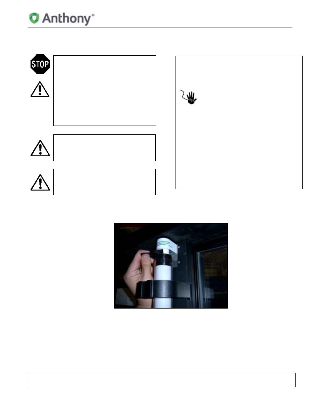
2. Removing Fluorescent Lighting
1. Remove fluorescent light bulbs.
Read and observe all CAUTIONS and WARNINGS
shown throughout these instructions. While
performing installations described; gloves, safety
glasses or goggles should be worn.
PREPARE ELECTRICAL WIRING
Electrical requirements
This appliance must be supplied with 120V, 60 Hz,
and connected to an individual and properly
grounded branch circuit, protected by a 15 or 20
ampere circuit breaker or time delat fuse.
Grounding Instructions – Cable Direct
This lighting system must be connected to a
grounded metal, permanent wiring system, or an
equipment grounding connector must be run with
the system conductors and be connected to the
equipment grounding terminal or lead on the
lighting fixture.
99-17248-I001 – 401D, 1KDR & DisplayRite Optimax 2 Retrofit Manual
TITLE:
REV.
B
Page 4 of 17
401D, 1KDR & DisplayRite Optimax 2 Retrofit Manual
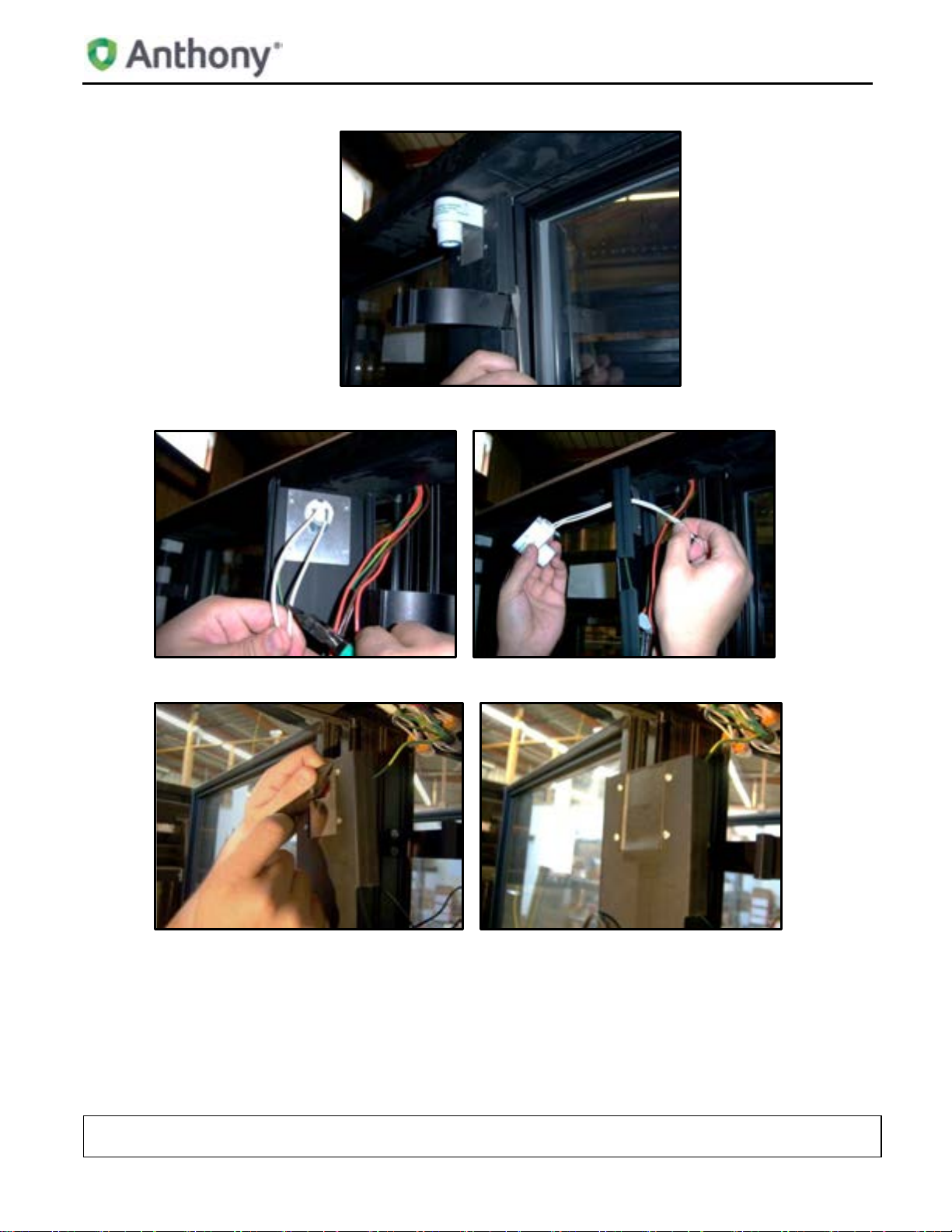
2. Detach mullion cover using a flat head screwdriver.
3. Remove lamp holders.
4. Cover lamp holder holes using foam tape (supplied).
TITLE:
99-17248-I001 – 401D, 1KDR & DisplayRite Optimax 2 Retrofit Manual
REV.
B
Page 5 of 17
2.1. Remove Ballasts
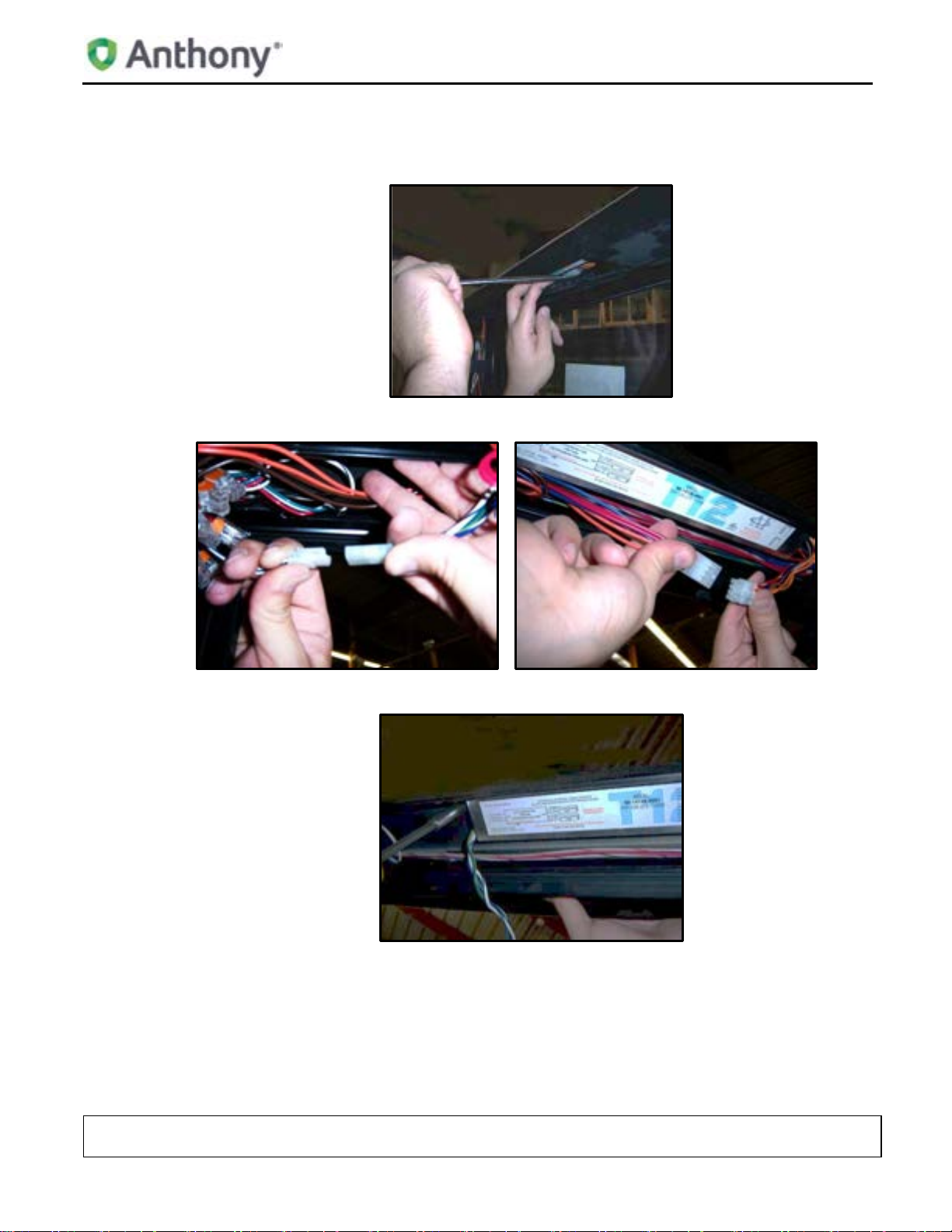
1. Remove raceway cover by inserting a flat screwdriver into the seam between the metal raceway and the plastic cover and pry open.
2. Unplug power and light connectors.
401D, 1KDR & DisplayRite Optimax 2 Retrofit Manual
3. With the ballast exposed, proceed to remove the screws.
Note: Do not discard screws, they will be used for mounting the drivers.
Note: Remove and dispose of existing ballasts per any local or Federal guidelines.
TITLE:
99-17248-I001 – 401D, 1KDR & DisplayRite Optimax 2 Retrofit Manual
REV.
B
Page 6 of 17

401D, 1KDR & DisplayRite Optimax 2 Retrofit Manual
3. Installing LED Fixtures
3.1. Installing LED Fixtures (Center Mullion) Model 401
1. Place LED fixture on mullion cover and drill two Ø 3/16” holes through round holes of end cap on each end.
2. Peel off tape liner from back of the fixture prior to installation.
3. Attach LED fixtures to mulli on usi ng four #8-32 X 5/8” screws and nuts (supplied).
TITLE:
99-17248-I001 – 401D, 1KDR & DisplayRite Optimax 2 Retrofit Manual
REV.
B
Page 7 of 17

401D, 1KDR & DisplayRite Optimax 2 Retrofit Manual
4. Drill a Ø 3/8” hole about ½” from the end cap and install the supplied bushing.
5. Feed wires through bushing.
6. Connect light wires from LED fixture to wire assembly using WAGO connectors or other Anthony approved connector.
TITLE:
99-17248-I001 – 401D, 1KDR & DisplayRite Optimax 2 Retrofit Manual
REV.
B
Page 8 of 17

401D, 1KDR & DisplayRite Optimax 2 Retrofit Manual
3.2. Installing LED Fixtures (End Mullion) Model 401
1. Place LED fixture over end mullion cover and align edge of LED fixture with edge of end mullion cover. Drill two Ø 3/16” through slots of end cap.
2. Attach LED fixture usin g #8-32 X 5/8” screws and nuts suppl i ed. Pr o c eed to wire fixture as described in step 6 of Installing LED Fixtures (Center Mullion) Model 401.
3. Reinstall mullion covers.
Note: Seal any open holes using neutral cure silicone to prevent air infiltration.
TITLE:
99-17248-I001 – 401D, 1KDR & DisplayRite Optimax 2 Retrofit Manual
REV.
B
Page 9 of 17

401D, 1KDR & DisplayRite Optimax 2 Retrofit Manual
3.3. Installing LED Fixtures Model 1KDR w/ELS Option
1. Remove lens assembly and fluorescent light bulbs.
2. Detach mullion cover using a flat head screwdriver.
3. Remove lamp holder assemblies.
TITLE:
99-17248-I001 – 401D, 1KDR & DisplayRite Optimax 2 Retrofit Manual
REV.
B
Page 10 of 17

401D, 1KDR & DisplayRite Optimax 2 Retrofit Manual
4. Place LED fixture on mullion cover and drill two Ø 3/16” holes through round holes of end cap on each end.
5. Peel off tape liner from back of the fixture prior to installation.
6. Cover exposed holes with foam tape supplied and feed wires through the tape and one of the upper holes.
TITLE:
99-17248-I001 – 401D, 1KDR & DisplayRite Optimax 2 Retrofit Manual
REV.
B
Page 11 of 17

401D, 1KDR & DisplayRite Optimax 2 Retrofit Manual
7. Attach LED fixtures to mulli on usi ng fo ur #8-32 X 5/8” screws and nut s (supplied).
8. Place LED fixture over end mullion cover and drill one Ø 3/16” hole through slot of end cap on each end.
9. Cover exposed rectangular hole with foam tape supplied and feed wires through the tape and hole and re-install mullion covers.
TITLE:
99-17248-I001 – 401D, 1KDR & DisplayRite Optimax 2 Retrofit Manual
REV.
B
Page 12 of 17

401D, 1KDR & DisplayRite Optimax 2 Retrofit Manual
3.4. Installing LED Fixtures DisplayRite w/Power Lens Option
1. For light removal follow the same steps as for the Model 1KDR.
2. Apply the ½” X ½” foam supplied to the back of each of the light fixtures prior to installation.
3. For the center mullion, follow step 4 of Installing LED Fixtures Model 1KDR w/ELS Option.
4. For the end mullion cover, carefully score plastic cover and snap extrusion section.
TITLE:
99-17248-I001 – 401D, 1KDR & DisplayRite Optimax 2 Retrofit Manual
REV.
B
Page 13 of 17

401D, 1KDR & DisplayRite Optimax 2 Retrofit Manual
5. Place LED fixture over end mullion cover and drill one Ø 3/16” hole through slot of end cap on each end.
6. Cover rectangular hole with foam tape supplied and feed wires through the tape and hole and attach LED fixture using #8-32 X 5/8” screws and nuts supplied.
TITLE:
99-17248-I001 – 401D, 1KDR & DisplayRite Optimax 2 Retrofit Manual
REV.
B
Page 14 of 17

401D, 1KDR & DisplayRite Optimax 2 Retrofit Manual
4. Driver Installation
1. Install Driver in the same location where the ballast was fitted using existing selftapping screws. (Installer may have to drill two holes in raceway to accommodate
driver).
2. If no connector is found on driver, cut off blue and white wires from harness and connect to driver using Wago connectors or other Anthony approved connectors.
3. Connect light wires from LED fixture to red and black wires from driver.
4. Reinstall raceway covers and power up!
TITLE:
99-17248-I001 – 401D, 1KDR & DisplayRite Optimax 2 Retrofit Manual
REV.
B
Page 15 of 17

5. Wiring Diagram
401D, 1KDR & DisplayRite Optimax 2 Retrofit Manual
TITLE:
99-17248-I001 – 401D, 1KDR & DisplayRite Optimax 2 Retrofit Manual
REV.
B
Page 16 of 17

401D, 1KDR & DisplayRite Optimax 2 Retrofit Manual
F. Carbajal
Initial Release
05/16/2012
6. REVISION HISTORY PAGE
REV ORIGINATOR DESCRIPTION OF CHANGE EFFECTIVE DATE
S. Fisher
Reformat from Framemaker to Word 12/18/2012
TITLE:
99-17248-I001 – 401D, 1KDR & DisplayRite Optimax 2 Retrofit Manual
REV.
B
Page 17 of 17
 Loading...