


401B/1KDB
CoolRite/FreezeRite
Installation Manual
99-16105-I003

401B/1KDB & CoolRite/FreezeRite Installation Manual
Copyright © 2011 by
ALL rights reserved. Information in this document is subject to change without notice. Companies, names and data used in
examples herein are fictitious unless otherwise noted. No part of this document may be reproduced or transmitted in any form
or by any means, electronic or mechanical, for any purpose, without express permission of Anthony Manufacturing Co., Inc.
Anthony products identified in this manual are design ed and certified to meet or for safety, and for sanitation
standards.
European products meet requirements.
Each customer is responsible for final site appr ov al.
TITLE:
99-16105-I003 – 401B/1KDB & CoolRite/FreezeRite Installation Manual
REV.
D
Page 2 of 21

401B/1KDB & CoolRite/FreezeRite Installation Manual
TABLE OF CONTENTS
1. Preliminary Considerations for Door and Frame Servicing Procedures ............................... 4
1.1. Safety ........................................................................................................................ 4
1.2. Tools .......................................................................................................................... 4
1.3. Tips ............................................................................................................................ 4
2. Frame Installation an d Ser v i c e Maintenance ....................................................................... 5
2.1. Shimming .................................................................................................................. 5
2.2. To Install the Frame ................................................................................................... 6
2.3. Frame Electrical Wiring Connectio ns ......................................................................... 7
3. Door Installation and Service Maintenance (Model 401 & 1KDB) ........................................ 9
3.1. To Install the Door Assembly ..................................................................................... 9
3.2. Remove the Door Assembly (Model 401 & 1KDB) .................................................. 11
3.3. To Reverse the Door Swing (Model 1KDB Only) ..................................................... 13
3.3.1. Frame .......................................................................................................... 13
3.3.2. Door ............................................................................................................. 15
3.4. TorqueMaster™ and SAG Adjustment (Model 401B and1KDB) ............................. 16
4. CoolRite - FreezeRite Door Installati on ............................................................................. 17
4.1. To Install the CoolRite/FreezeRite Door Assembly .................................................. 17
4.2. To Remove the Door Assembly ............................................................................... 19
4.3. Torque Rite Adjustment ........................................................................................... 20
5. Revision History Page ....................................................................................................... 21
TITLE:
99-16105-I003 – 401B/1KDB & CoolRite/FreezeRite Installation Manual
REV.
D
Page 3 of 21
401B/1KDB & CoolRite/FreezeRite Installation Manual
1. PRELIMINARY CONSIDERATIONS FOR DOOR AND FRAME SERVICING PROCEDURES
1.1. Safety
Proper safety equipment includes:
NOTE: Turn off all electrical power prior to beginning work on the door or on any
electrical equipment. Use extra caution when working with or around the
door glass package.
NOTE: Do Not use power tools for the following procedures.
1.2. Tools
Tools required for this procedure include:
• #2 Phillips-head screwdriver Flat-head screwdriver
• Needle-nose pliers Rubber or plastic mallet
• 7/16” and 1/2” Hand Wrench 5/32” Hex Key
• Wire stripper and cutter Soldering iron
• Heat Gun Razor Knife
1.3. Tips
• Complete replacement of wire assemblies is recommended whenever
required. Splice wires only if necessary, using proper materials: such as
electrical tape, wire nuts, flux core solder and heat shrink.
• Apply liquid soap to rail plastic covers and gaskets upon installation to
facilitate insertion into mounting grooves.
• Keep doors and frames clean for product efficiency. This can also help
reduce energy consumption and potential health hazards.
• Whenever binding gasket or plastic parts, use food grade silicone.
• Whenever replacing fluorescent lamps, always replace lamp covers as well.
• Always use the correct tool for the job to be performed. This ensures proper
installation and minimizes safety risks.
• If there is any doubt about the work to be performed, consult with a certified
technician or Anthony representative.
• Preventative maintenance is recommended to ensure product longevity.
TITLE:
99-16105-I003 – 401B/1KDB & CoolRite/FreezeRite Installation Manual
REV.
D
Page 4 of 21

401B/1KDB & CoolRite/FreezeRite Installation Manual
2. FRAME INSTALLATION AND SERVICE MAINTENANCE
1. Read instructions completely before installing the frame.
• Clearance between the frame sill and the case bottom or floor is mandated by
local building codes.
• Sill net opening must be at minimum of two inches in height
• Sill must be completely level.
2. Before installing the frame, confirm the size of the net opening accommodates the
finish frame. If the tolerances are too high, the net opening will have to be enlarged.
3. Check size of finished frame to net opening.
4. Subtract the frame height measurement, from the net opening’s height measurement.
5. Subtract the fra me wi dth meas urem ent, from the net opening’s w i dth measur e me nt .
6. Divide each number in half. This is the amount of gap that will occur between the
frame and the net opening.
7. If the gap between the frame and the net opening is greater than 1/16”, shim the gap
for a proper fit.
2.1. Shimming
1. Acquire sturdy, penetrable material, such as plywood. The thickness of the
material should be wedge shaped or slightly less than the gap to be filled.
2. Measure the gap length (height or width of frame) and cut the shim material to
1/16” less than the measured length.
3. Install the shim using the same type of mounting hardware that will be used to
install the frame. Be certain that the shim installation hardware will not interfere
with the frame installation hardware
4. If necessary, cut a second shim to the same length and install it in the opposite
side of the net opening.
TITLE:
99-16105-I003 – 401B/1KDB & CoolRite/FreezeRite Installation Manual
REV.
D
Page 5 of 21
401B/1KDB & CoolRite/FreezeRite Installation Manual
5. If the adjacent sides of the net opening need shimming, repeat the previous
steps. Match the shim length to the frame sides of the net opening (less 1/16”).
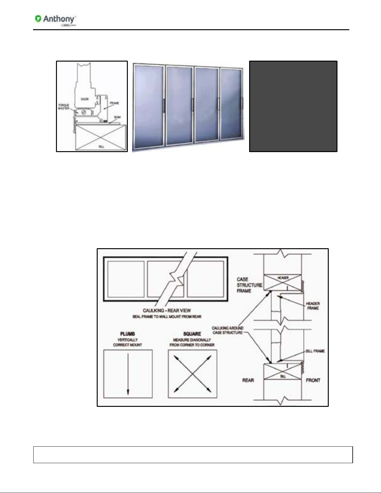
Anthony Door Sill Cross Section DisplayRite Sill Cross Section
with Sill Location with Sill Location
2.2. To Install the Frame
1. Verify openings conform to net openings listed in price book or original order.
2. Insert the finished frame assembly into the net opening. DO NOT for ce th e fra me
if the fit is too tight.
3. Insert a mounting screw into a mounting hole in each corner of the frame and
tighten each screw until it is approximately a quarter inch from flush.
4. Check the frame is aligned properly or square.
Frame Installation Reference
5. Use a measuring tape to measure diagonally one corner to the opposite and note
the distance.
6. Measure the distance between the remaining two corners.
TITLE:
99-16105-I003 – 401B/1KDB & CoolRite/FreezeRite Installation Manual
REV.
D
Page 6 of 21

401B/1KDB & CoolRite/FreezeRite Installation Manual
7. Both measurements should be the same, within a 1/16” difference.
8. Confirm the frame and frame flanges are vertically aligned to the wall surface
around the net opening.
9. Place a level on the top flange of the header frame to check if it is horizontally
aligned.
10. If the top of the header frame sags or bows, correct as necessary.
11. When the frame is aligned, tighten all mounting screws securely until each is
flush to the frame surface.
12. DO NOT over-tighten the screws, as this can cause the frame to become out of
square.
13. Check entire frame to ensure installation is correct.
NOTE: Use caulk and food grade silicone sealant to seal the gap bet ween the
frame and the surrounding wall, inside case, cooler or freezer.
2.3. Frame Electrical Wiring Connections The seven individual wires extending from the flexible conduit atop the frame,
provide electrical power to various frame and door functions. Refer to the wiring
diagram label, affixed to the frame header.
Wire Diagram Connection Label
TITLE:
99-16105-I003 – 401B/1KDB & CoolRite/FreezeRite Installation Manual
REV.
D
Page 7 of 21

401B/1KDB & CoolRite/FreezeRite Installation Manual
Using wire connectors, these wires should be grouped by the Hot wires (Circuit
wires), the Neutral wires and the ground wire for connection to either the facility or
the case power.
Wiring Diagram
• Blue/White wire connects to the supplied Hot (or Lights Circuit Wire).
• White/Blue wire connects to the supplied Light neutral wire.
• Red and Black wires connect to the supplied Hot (or Door/Frame Heater
Circuit Wire).
• White/Red and White/Black wires connect to the supplied neutral wire for
Door/Frame Circuit.
• Green/Yellow wire connects to the supplied ground wire.
NOTE: W iring for lights should have a separate circuit from the door/frame
heater wiring circuit.
TITLE:
99-16105-I003 – 401B/1KDB & CoolRite/FreezeRite Installation Manual
REV.
D
Page 8 of 21

401B/1KDB & CoolRite/FreezeRite Installation Manual
3. DOOR INSTALLATION & SERVICE MAINTENANCE (MODEL 401 & 1KDB)
3.1. To Install the Door Assembly
1. Hold the door on each side, with the handle facing forward. Lift the door, and
align the torque rod to insert into the TorqueMaster™ socket at the base of the
frame.
Insert Torque Rod
2. Engage the door with the hinge pin inserted into the Gib (hinge pi n pl ug )
receptacle at the top of the frame. Push the door into the frame until the hinge pin
snaps into place.
Connect Hinge Pin
NOTE: Verify that the torque rod and hinge pin are secured before releasing the
door.
3. Insert the hold-open bolt through the elongated hold-open slot.
TITLE:
99-16105-I003 – 401B/1KDB & CoolRite/FreezeRite Installation Manual
REV.
D
Page 9 of 21

401B/1KDB & CoolRite/FreezeRite Installation Manual
4. Insert the washer and the hold-open bolt into the frame mounting hole and tighten the bolt, use a 7/16” open-ended hand wrench.
Tighten Hold-Open Bolt
5. Set the door tension swing and correct the door alignment by adjusting the
TorqueMaster™. (See “TorqueMaster™ and SAG Adjustment (Model 401B
and1KDB)”.
Torquemaster Assembly
NOTE: DO NOT use power tools when adjusting the TorqueMaster™.
NOTE: DO NOT over tighten hold-open bolt. Verify hold-open does not bind
while sliding along the hold-open bolt . Adjus t as nec ess ar y .
TITLE:
99-16105-I003 – 401B/1KDB & CoolRite/FreezeRite Installation Manual
REV.
D
Page 10 of 21

401B/1KDB & CoolRite/FreezeRite Installation Manual
3.2. Remove the Door Assembly (Model 401 & 1KDB)
1. Release tensio n on the TorqueMaster™ with a flat-head screwdriver. Turn the
TorqueMaster™ front facing screw clockwise, until the door does not
automatically close from an open position.
Release Torquemaster Tension
2. Open the door to access the hold open device, then loosen and remove the
hold-open detent bolt using a 7/16” hand wrench.
Remove Hold-Open Bolt
3. Retract the door to a near-c l osed pos it ion.
TITLE:
99-16105-I003 – 401B/1KDB & CoolRite/FreezeRite Installation Manual
REV.
D
Page 11 of 21

401B/1KDB & CoolRite/FreezeRite Installation Manual
4. Remove the hinge pin plug from the frame by inserting the top-half of needlenose pliers into the spring clip grip hole and the bottom half beneath the hinge
pin shroud.
Hing e Pin A ssembly Disengage Hinge Pin
Compress pliers to clamp down on the hinge pin spring clip, then simultaneously pull the hinge pin away from the frame and pull the door top out.
Withdraw from Hinge Gib
Lift the door out of the TorqueMaster™. Secure or lean the door on its side against a stable surface.
Withdraw from Frame
TITLE:
99-16105-I003 – 401B/1KDB & CoolRite/FreezeRite Installation Manual
REV.
D
Page 12 of 21

401B/1KDB & CoolRite/FreezeRite Installation Manual
3.3. To Reverse the Door Swing (Model 1KDB Only) Model 1KDB doors are reversible. Remove the door from the frame first and then
perform the following steps.
3.3.1. Frame
1. To remove the Torquemaster, insert a flat-head screwdriver into the top
center cutout in the Torquemaster, and turn the mounting screw counterclockwise for less than ½ turn. Lift the Torquemaster off the frame.
Remove Torquemaster
2. Pry off the plug cap (underneath) from the mounting hole, on the opposite
side of the doorframe with a flat-head screwdriver.
Remove Plug Cap
TITLE:
99-16105-I003 – 401B/1KDB & CoolRite/FreezeRite Installation Manual
REV.
D
Page 13 of 21

401B/1KDB & CoolRite/FreezeRite Installation Manual
3. Set the Torq uemas ter on the opened mounting hole. Align the flanged
corners of the mounting tabs with the SAG ADJUSTMENT screw facing
the inside of the frame.
Mount Torquemaster
4. Use the flat-head screwdriver and turn the Torquemaster mounting
setscrew clockwise for ½ turn, to tighten the mounting flange and lock it in
place.
5. Relocate and install the hold-open stand-offs and spacer into the opposite
hold-open mount of the same door fr am e.
Insert Stand-Off
TITLE:
99-16105-I003 – 401B/1KDB & CoolRite/FreezeRite Installation Manual
REV.
D
Page 14 of 21

401B/1KDB & CoolRite/FreezeRite Installation Manual
3.3.2. Door
1. Access the hinge pin wire connections in the rail on the hinge side of the
door assembly.
2. Disconnect the Hot, Neutral, and Ground wires of the hinge pin.
Hinge Pin Wires
3. Loosen and remove the hinge pin assembly from the top door rail.
4. Using a plastic mall et and a fla t-head screwdriver, remove the torque rod
from the bottom of the door assembly.
Remove Torque Rod
5. Reinstall the hing e pi n and the torq ue rod into the opposite ends of the
door assembly.
6. Reconnect the hinge pin wires and confirm all connections.
7. Check and confirm torque rod and hinge pin are correctly installed.
8. Reinstall the door into the frame per the door installation procedures.
TITLE:
99-16105-I003 – 401B/1KDB & CoolRite/FreezeRite Installation Manual
REV.
D
Page 15 of 21

401B/1KDB & CoolRite/FreezeRite Installation Manual
3.4. TorqueMaster™ and SAG Adjustment (Model 401B and1KDB)
The TorqueMaster™ regulates the door alignment and the door closing tension.
1. Use a flathead screwdriver to adjust the torque rod tension, by turning the
outside screw on the TorqueMaster™.
• Turn counter-clockwise to increase tension.
• Turn clockwise to decrease the tension.
2. Adjust the door sag to square the door in the frame, by turning the screw that is
marked SAG ADJ. (sag adjustment) on the end of the TorqueMaster™, until the
door is aligned square in the opening.
• Turn counter-clockwise to raise handle side of door.
• Turn clockwise to lower the handle side of door.
NOTE: DO NOT use power tools when adjusting the TorqueMaster™.
TITLE:
99-16105-I003 – 401B/1KDB & CoolRite/FreezeRite Installation Manual
REV.
D
Page 16 of 21

401B/1KDB & CoolRite/FreezeRite Installation Manual
4. COOLRITE - FREEZERITE DOOR INSTALLATION
4.1. To Install the Coolrite/Freezerite Door Assembly
1. Hold the door on each side, with the handle facing forward. Lift the door and align it with torque rod to insert it into the Torque Rite socket at the base of the frame.
DisplayRite Parts Assemblies
2. Seat the torque-rod wheel into the Torque Rite gear. The door weight will now rest on the frame.
Torque Rite Assembly
TITLE:
99-16105-I003 – 401B/1KDB & CoolRite/FreezeRite Installation Manual
REV.
D
Page 17 of 21

401B/1KDB & CoolRite/FreezeRite Installation Manual
3. Align the top spring-loaded hinge pin with the hinge pin opening in the frame.
4. Press down on the spring loaded hinge pin (while moving the door back into the frame opening), until the hinge pin engages into the hinge pin opening.
Engage Hinge Pin
5. Secure the door with the black door retainer clip. Hold the clip by the tab and insert it onto the exposed part of the top hinge pin. The clip will fit tightly.
Insert Retainer Clip
NOTE: The door retainer clip must be in place to ensure the door cannot lift off from
the Torque Rite during use.
6. Fasten the hold-open arm to frame top with the hold open bolt provided.
Install Hold-Open Door Arm
TITLE:
99-16105-I003 – 401B/1KDB & CoolRite/FreezeRite Installation Manual
REV.
D
Page 18 of 21

401B/1KDB & CoolRite/FreezeRite Installation Manual
7. Plug the door heater cord into the three-pin receptacle on the inside of the frame
top. Secure the plug with the attached 5/8” Phillips head screw.
8. Set the door tension by adjusting the Torque Rit e. (See Torque Rite Adjustment).
4.2. To Remove the Door Assembly
Connect Electrical Plug
1. Release tension on Torque Rite prior to removing the door from the frame. Two
1/8” square wire-rods are necessary. Insert one wire-rod in the Paw Lever
opening and one wire-rod in the torque rod adjusting wheel slot.
2. Turn the torque rod adjusting wheel slightly toward the handle to free the Paw Lever, push the second rod inward, and release wheel in opposite direction.
3. On the door heater cord, unscrew the attached 5/8” Phillips head screw from the
frame receptacle and unplug the cord.
4. Uninstall the bolt securing the hold-open arm from the top fra me rec eptac le.
5. Remove the hinge pin retainer door clip.
6. Push down on the hinge pin and lean door out of the frame opening.
7. Lift door out of Torque Rite. Secure or lean door on its side against a stable
surface.
TITLE:
99-16105-I003 – 401B/1KDB & CoolRite/FreezeRite Installation Manual
REV.
D
Page 19 of 21

401B/1KDB & CoolRite/FreezeRite Installation Manual
4.3. Torque Rite Adjustment
1. Use a 1/8” square wire-rod to adjust door-closing tension. Insert one square wire-rod into adjusting slot and turn torque rod wheel in the direction of the handle, until the door shuts by itself. 4 to 6 clicks maximum.
Torque Rite Identification
2. To release torque tension, insert two 1/8” square wire-rods: one into the Paw
Lever opening and one in the torque rod adjusting wheel slot. With the first
rod, turn the adjusting wheel toward Paw Lever and push second rod inward
and release wheel in the opposite direction.
3. When the door is out of alignment, adjust the Torque Rit e sag adj us t men t screw to the appropriate setting.
NOTE: Torque Rite Paw Lever should always face outward. It is used to release
tension on the door by inserting a second 1/8” square rod.
TITLE:
99-16105-I003 – 401B/1KDB & CoolRite/FreezeRite Installation Manual
REV.
D
Page 20 of 21

401B/1KDB & CoolRite/FreezeRite Installation Manual
A
SWatstein
Prelim Release Only
November 2008
5. REVISION HISTORY PAGE
REV ORIGINATOR DESCRIPTION OF CHANGE EFFECTIVE DATE
B
C
D
SWatstein
SWatstein
S. Fisher
Log and font update 05/13/2010
Format Change 05/27/2010
Reformat from PDF t o Word 03/21/2013
TITLE:
99-16105-I003 – 401B/1KDB & CoolRite/FreezeRite Installation Manual
REV.
D
Page 21 of 21
 Loading...