

Anthony 101E Installation Manual
Model 101E
Installation Manual
12391 Montero Street, Sylmar, CA 91342
Anthony Inc.
800.772.0900 www.anthonyintl.com
99-18085-I001_B

Copyright © 2010 by
ALL rights reserved. Information in this docume
examples herein are fictitious unless otherwise noted. No part of this document may be reproduced or transmitted in any form or
by any means, electronic or mechanical, for any purpose, without express permission of Anthony Manufacturing Co., Inc.
Anthony products identified in this manual are designed and certified to meet or for safety, and for sanitation
standards.
European products meet requirements.
Each customer is responsible for final site approval.
nt is subject to change without notice. Companies, names and data used in

Table of Contents
TABLE OF CONTENTS
Preliminary Considerations for Door and Frame Servicing Procedures . . . . . . . . . . . . . . . . . . . . . . . . . 1
Safety................................................................................................................................................................... 1
Tools .................................................................................................................................................................... 1
Tips ...................................................................................................................................................................... 1
DOOR REMOVAL & REVERSAL . . . . . . . . . . . . . . . . . . . . . . . . . . . . . . . . . . . . . . . . . . . . . . . . . . . . . . . . . 2
Removing the Door Assembly from the frame..................................................................................................... 2
Reversing the Door Swing ................................................................................................................................... 3
DOOR MAINTENANCE & PARTS REPLACEMENT . . . . . . . . . . . . . . . . . . . . . . . . . . . . . . . . . . . . . . . . . . 5
Removing and Replacing the Door Gasket ......................................................................................................... 5
Removing and Replacing the Door Rail Plastic Cover ........................................................................................ 7
Removing and Replacing the Torque Rod........................................................................................................... 8
Removing the Hold-Open Assembly.................................................................................................................... 9
Replacing the Hold-Open Assembly.................................................................................................................... 9
Door Heater Wire Replacement......................................................................................................................... 10
Removing and Replacing the Hinge Pin ............................................................................................................ 13
Ordering Replacement Doors ............................................................................................................................ 14
REPLACEMENT DOOR INSTALLATION . . . . . . . . . . . . . . . . . . . . . . . . . . . . . . . . . . . . . . . . . . . . . . . . . . 15
Installing the Door Assembly into the Frame ..................................................................................................... 15
Torque and Sag Adjustment .............................................................................................................................. 16
FRAME MAINTENANCE & PARTS PLEACEMENT . . . . . . . . . . . . . . . . . . . . . . . . . . . . . . . . . . . . . . . . . . 17
TorqueMaster Replacement .............................................................................................................................. 17
Power Receptacle Replacement ....................................................................................................................... 19
Bottom, Mullion and Full Perimeter Fiberglass Heater Wire Replacement........................................................ 20
SALES FRAME LAYOUT . . . . . . . . . . . . . . . . . . . . . . . . . . . . . . . . . . . . . . . . . . . . . . . . . . . . . . . . . 21
06-16875-0000 (Sheet 1 of 7)............................................................................................................................ 21
06-16875-0000 (Sheet 2 of 7)............................................................................................................................ 22
06-16875-0000 (Sheet 3 of 7)............................................................................................................................ 23
06-16875-0000 (Sheet 4 of 7)............................................................................................................................ 24
06-16875-0000 (Sheet 5 of 7)............................................................................................................................ 25
06-16875-0000 (Sheet 6 of 7)............................................................................................................................ 26
06-16875-0000 (Sheet 7 of 7)............................................................................................................................ 27
5/27/2010 i 99-18085-I001_B
Instructions
Preliminary Considerations for Door and Frame Servicing Procedures
Safety
Proper safety equipment includes:
safety glasses work gloves work shoes
NOTE: TURN OFF ALL ELECTRICAL POWER PRIOR TO BEGINNING
WORK ON THE DOOR OR ON ANY ELECTRICAL. USE EXTRA CAUTION
WHEN WORKING WITH OR AROUND THE DOOR GLASS PACKAGE.
NOTE: DO NOT USE POWER TOOLS FOR THE FOLLOWING
PROCEDURES
Tools
Tools required for this procedure include:
- #2 Phillips-head screwdriver - Flat-head screwdriver
- Needle-nose pliers - Rubber or plastic mallet
7
-
/16” and 1/2” Hand Wrench - 5/32” Hex Key
- Wire stripper and cutter - Soldering iron
- Heat Gun -
Tips
• Complete replacement of wire assemblies is recommended whenever required. Splice wires only if necessary
using proper materials such as, electrical tape, wire nuts, flux core solder and heat shrink.
• Apply liquid soap to rail plastic covers and gaskets upon inst
• Keep doors and frames clean for product efficiency. This can also help reduce energy consumption and potential health hazards.
• Whenever binding gasket or plastic
Razor Knife
p
arts, use food grade silicone.
allation
to facilitate insertion into mounting grooves.
5/27/2010 1 99-18085-I001_B
Instructions
• Whenever replacing fluorescent lamps, always replace lamp covers as well.
• Always use the correct tool for the job to be performed. Th
risks.
• If there is any doubt about the work to be performed, co
tive.
• Preventative maintenance is recommen
to ensure product longevity.
ded
is ensures proper installation and minimizes safety
sult with a certified technician or Anthony representa-
n
DOOR REMOVAL & REVERSAL
Removing the Door Assembly from the frame.
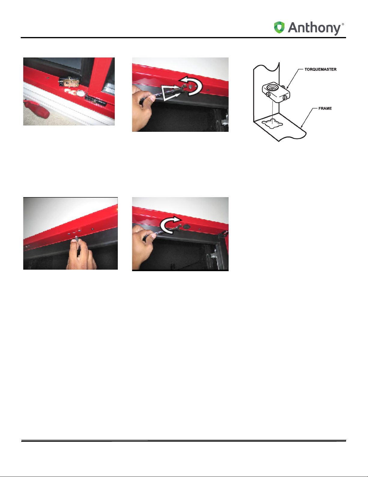
1. Using a flat-head screwdriver, loosen the tension on the door by turning the adjustment screw, located on the
front of the torquemaster, to the right or clockwise. Refer to A
2. Test the door by opening it, and confirm that the torque tension does not retract the door from open position.
3. If tension remains, continue adju
s
ting the torquemaster until all tension has been removed from the door.
4. Open the door to access the hold open device then loosen and remove
hold-open bolt, using
a phillips-head screwdriver. Refer to B
A
5. Remove the hold open stud using a 7/16” hand wrench.
6. Retract the door to a near-closed position.
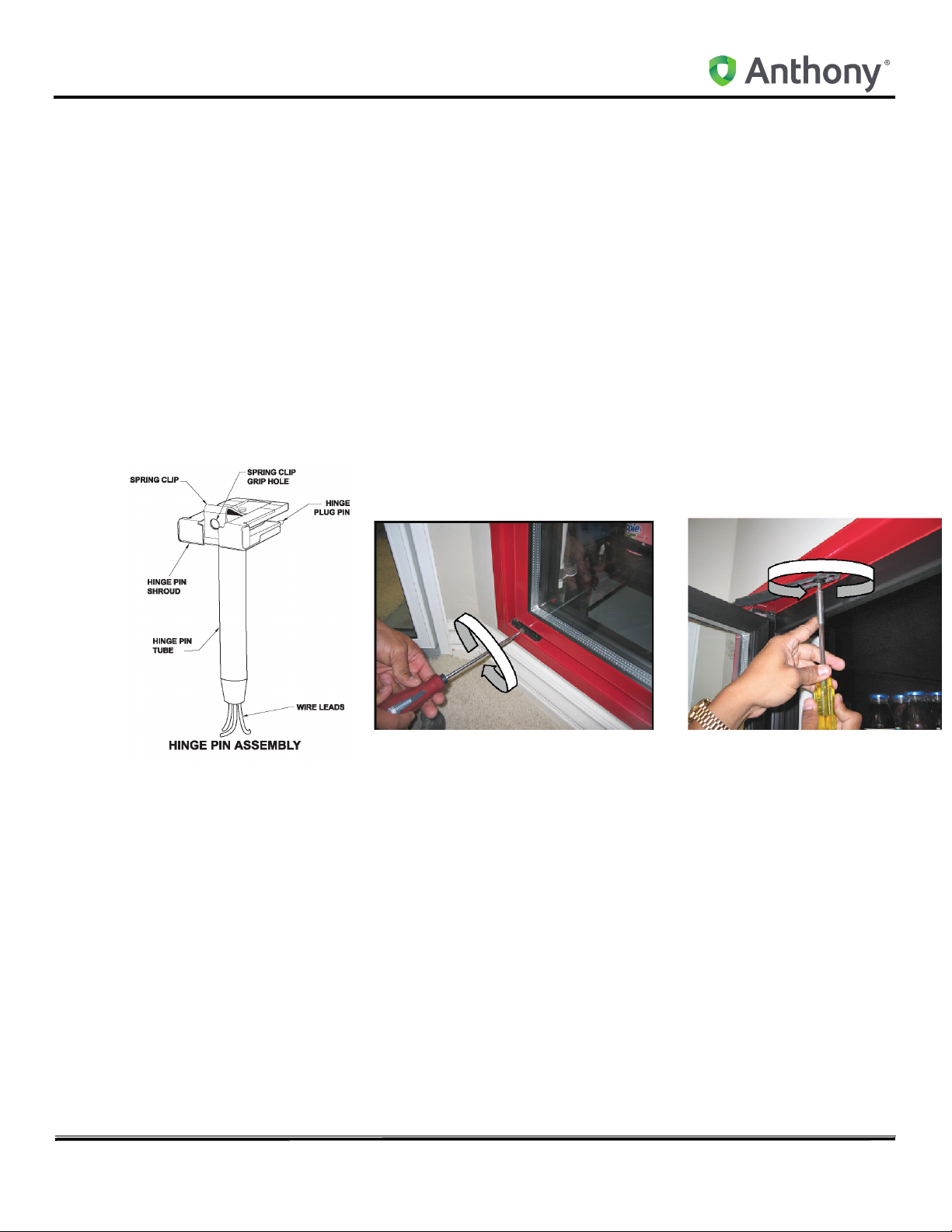
7
. Insert the top half of the needle-nose pliers into the grip-h
half of the pliers beneath the hinge pin shroud. Refer to C
ole, located in the hinge pin spring-clip, and the bottom
B
5/27/2010 2 99-18085-I001_B
Instructions
8. Squeeze the pliers to clamp down on the hinge pin spring clip, allowing the clip to release the hinge pin from the
receptacle gib of the frame, while simultaneously pulling the top of the door away from the frame. This will release
and pull the hinge pin out of the hinge pin receptacle and gib. Refer to D
C
D
E
9. Continue pulling the top of the door
10. Lift and remove the door from the torquemaster and carefully set the door aside. Refer to E
asse
mbly away from the frame until the top door rail clears the frame.
Reversing the Door Swing
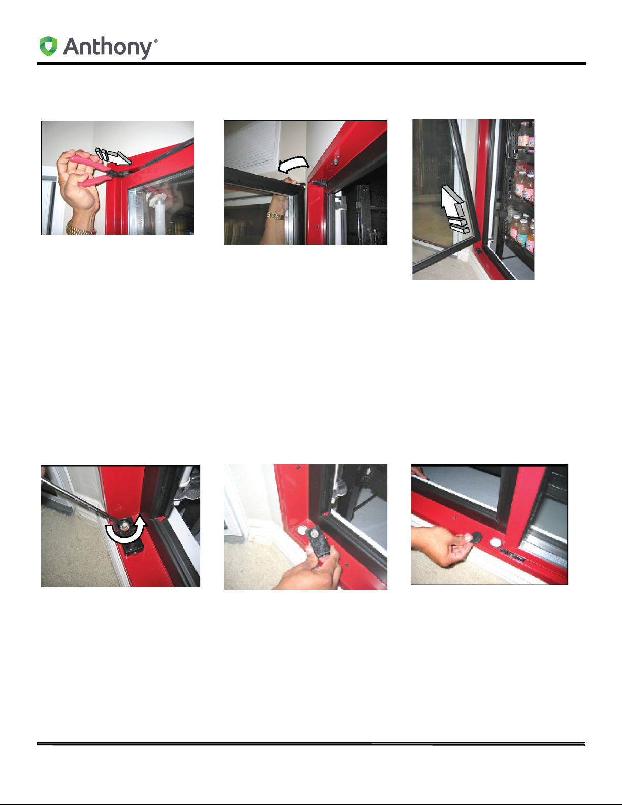
1. Using a flat-head screwdriver, loosen the torquemaster from its mount by turning the center mounting screw
counter-clockwise less than one-half (1/2) of a turn. Refer to A
2. Remove the Torquemaster, exposing the mounting hole in the bottom frame rail. Refer to B
3. Locate the mounting hole at the opp
4. Using the flat-head screwdriver, carefully pry underneath the plug cap and remove it. Refer to C
A
osite sid
B
e of the door opening.
C
5. Place the Torquemaster on the newly opened mounting ho
Refer to D
6. Insert the Torquemaster mounting tabs onto the mounting h
the door frame.
7. Confirm that the mounting flanges on the bottom of the
mounting hole in the frame.
8. Using a flat-head screwdriver, turn the Torquemaster mounting set-screw clockwise, for 1/2 a turn, to tighten the
mount
lock it in place. Confirm that the torquemaster mounting is flush with the door frame.
and
le, aligning the flanged corners of the mounting tabs.
le with the hollow end of the Torquemaster against
o
rquemaster align with the corner mounting slots of the
to
5/27/2010 3 99-18085-I001_B
Instructions
9. Using a 7/16” open-ended hand wrench, loosen and remove the hold-open detent bolt and standoff. Refer to E
D
E
10. Relocate and install the hold-open detent bolt and standoff into the opposite hold-open mount of the same door
fram
e. Refer to F and refer to G
NOTE: The standoff and screw will be switched from the door rail to the frame and the detent bolt and
washer will be switched from the frame to the door.
F
11. Open the access portal to the hinge pin wire connections in the rail on the hinge side of the door assembly.
G
5/27/2010 4 99-18085-I001_B
H
Instructions
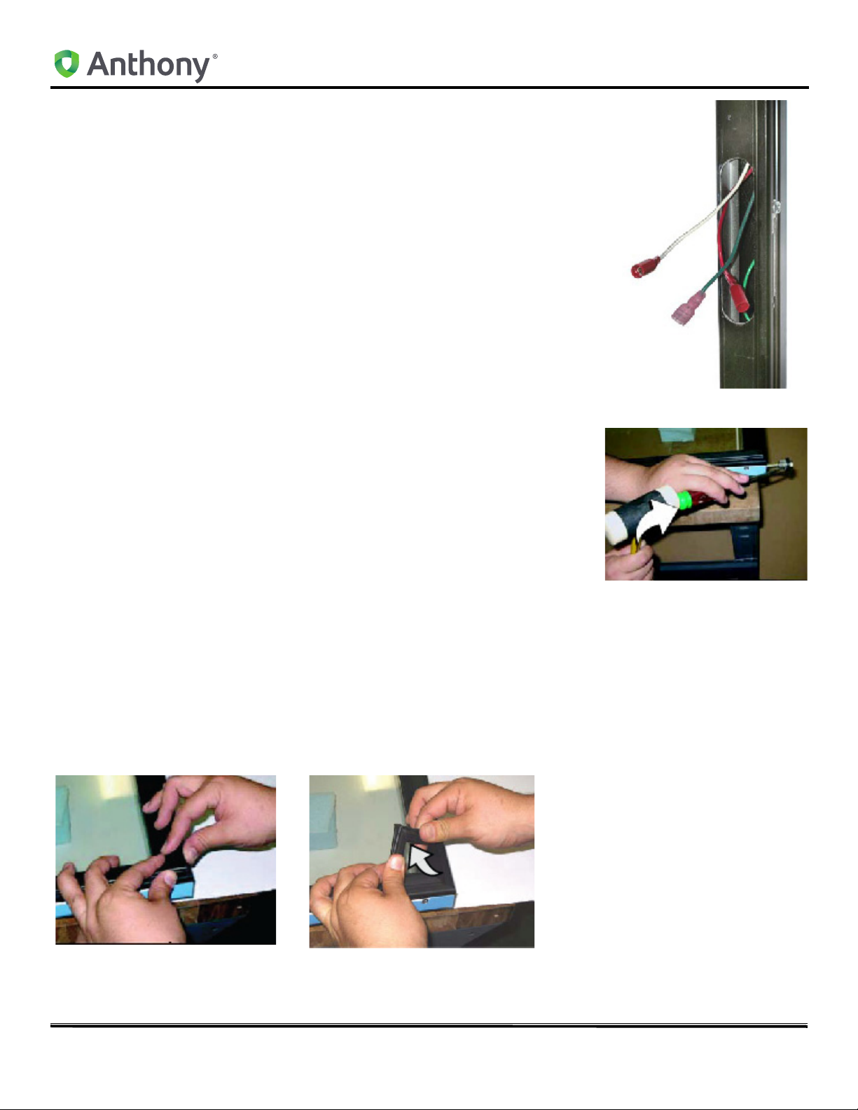
12. Disconnect the Hot, Neutral and Ground wires of the hinge pin from the heater
wire circuit and the ground terminal. Refer to H
13. Loosen and completely remove the hinge pin assembly from the top door rail.
NOTE: Refer to the Hinge Pin Replacement instructions in Section II for
complete replacement procedures.
14. Using a plastic mallet and a flat-head screwdriver, remove the torque rod from
the bottom of the door assembly. (I)
NOTE: Refer to the Removing and Replacing Torque Rod instructions in
Section II for complete Torque Rod replacement instructions.
15. Swap placement of the Hinge Pin and Torque Rod to the other’s original
mounting hole in the door assembly hinge side rail.
16. Reinstall the hinge pin and the torque rod completely into the ends of the door
asse
mbly hin
17. If necessary, lightly tap on the hinge pin and torque rod with a plastic or rubber
malle
t un
18. Reconnect the hinge in wires and confirm tha
19. Check and confirm torque rod and hinge pin are correctly and completely
installed.
20
. Reinstall the door into the frame.
ge rail.
til each is fully seated into the top and bottom of the door.
all connections are secure.
t
NOTE: Refer to door replacement procedures in Section II for complete door installation instructions.
DOOR MAINTENANCE & PARTS REPLACEMENT
Removing and Replacing the Door Gasket
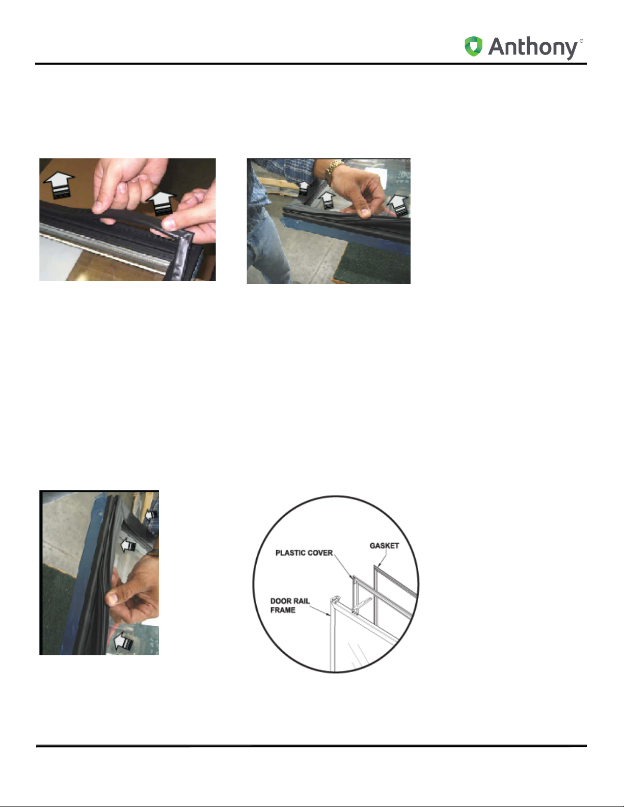
1. Begin removing the door gasket by lifting one corner of the gasket out of the groove. Refer to A and refer to B )
A
5/27/2010 5 99-18085-I001_B
B
Instructions
2. Carefully pull the gasket out of the groove in the plastic rail covers. Refer to C and refer to D
NOTE: The gasket is composed of soft materials with welded miter joints. Use extra care when
manually extracting the gasket from the rail grooves to prevent damaging it as well as the plastic
rail.Align the two top corners of the replacement gasket onto the top mitered corners of the plastic
cover, with the gasket arrow facing the door rail and cover.
C
3. Align the two top corners of the replacement gasket onto the top mitered corners of the plastic cover, with the
gasket arrow facing the door rail and cover.
4. Press the gasket arrow into the groove in the center of th
arrow catch and the arrow is initially inserted into the groove of the plastic cover.
5. Align the bottom two gasket corners with the bottom mitered corners of the plastic covers, aligning the gasket
ar
w with the groove in the plastic cover and press the corners into the groove until the arrow is fully inserted.
ro
6. Press the gasket firmly against the top plastic cover, slid
the gasket, forcing the gasket arrow into the of the groove in the plastic top cover. Refer to E
7. Continue pressing the gasket arrow into the grooves of th
perimeter (if necessary, a plastic or rubber mallet can be used to facilitate the arrow into the groove by applying a
swift stroke onto the gasket- DO NOT damage the gasket or the glass).
8. Confirm that the entire gasket arrow has been completely inser
D
e plastic
ing fro
e re
cover corners until the edges of the gasket
m side to side and applying full pressure against
maining plastic covers, around the entire door rail
t
ed into the grove of all four plastic rail covers.
E
5/27/2010 6 99-18085-I001_B
Instructions
Removing and Replacing the Door Rail Plastic Cover
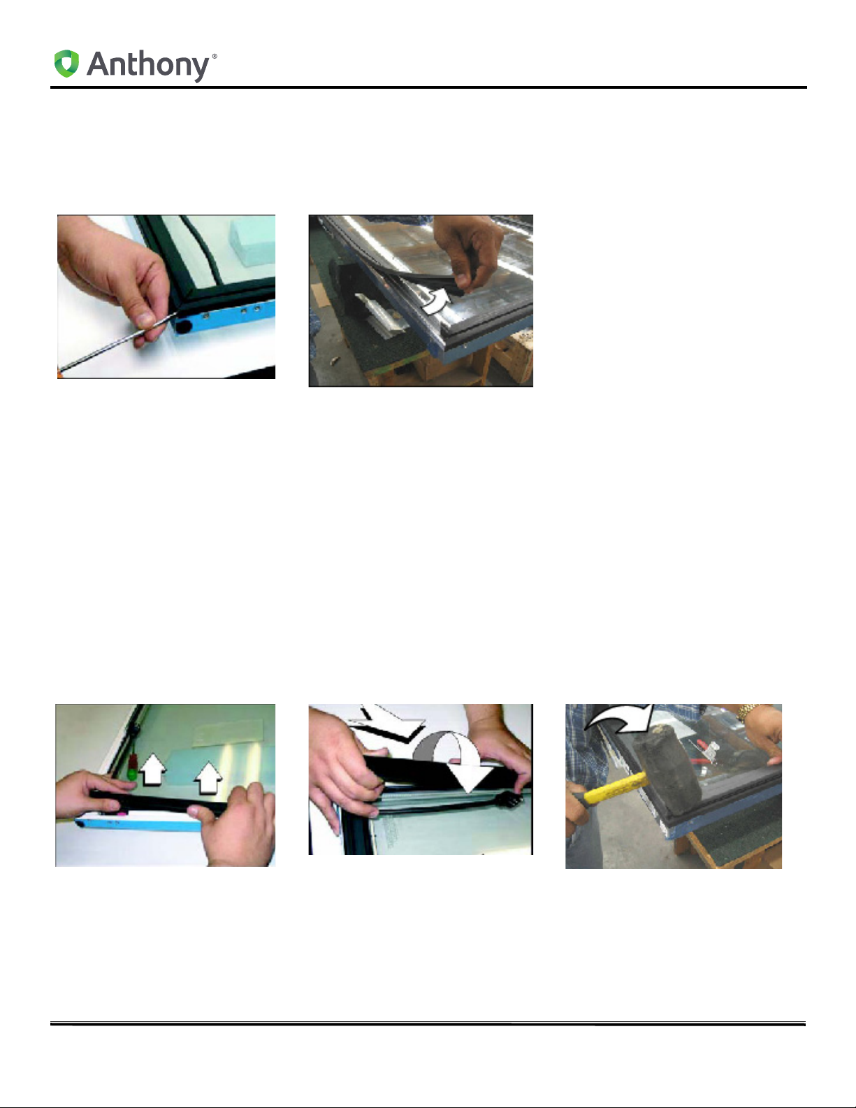
1. Insert the end of a slot head screwdriver in between two plastic cover ends at the corner miter. Refer to A
2. Carefully twist the screwdriver to loos
3. Continue to pry the plastic cover from the door rail until
en the corner of the plastic cover lip from the door rail.
the entire end of the plastic rail is disengaged. Refer to B
A
4. Pull the plastic cover up and out of door rail grooves until the entire plastic cover is removed from the door rail.
Refer to C
5. Repeat Steps Two (2) through Four (4) to loosen and remove the three remaining plastic covers.
6. To install the new, replacement plastic covers, begin b
door rail.
7. Insert the outer edge of the plastic cover into the outside groove of one of the door rails. Refer to D
8. Push the plastic cover down and inward, toward from the center of the door.
9. Slide along the entire length of the plastic cover while fir
sure down along the length of the entire door rail, inserting both the outside lip and the inside lip into the door rail
grooves simult
aneously.
B
y
aligning the replacement plastic cover evenly onto the
ly applying pressure against it. Continue applying pres-
m
NOTE: Carefully tapping the plastic cover using a plastic or rubber mallet with deliberate strokes,
outward and away from the glass, may help seat the lips of the plastic cover into the grooves of the
door rails. Refer to E
C
10. Check the entire plastic cover and confirm that both the inside and outside lips are fully inserted into the door rail
grooves.
11. Repeat this procedure, aligning each mitered corner, with th
are properly installed onto door rails.
12. Confirm that each plastic cover
is fully inst
alled and the mitered corners properly aligned.
maining plastic covers until all four plastic covers
e re
E
5/27/2010 7 99-18085-I001_B
D
 Loading...