

Anthony 101B Service Manual
101B, 210X, ELM, 101X Frame
Installation & Service Manual
99-16105-S001

101B, 210X, ELM, 101X Frame Installation & Service Manual
Copyright © 2011 by
ALL rights reserved. Information in this document is subject to change without notice. Companies, names and data used in
examples herein are fictitious unless otherwise noted. No part of this document may be reproduced or transmitted in any form or by
any means, electronic or mechanical, for any purpose, without express permission of Anthony Manufacturing Co., Inc.
Anthony products identified in this manual are design ed and certified to meet or for safety, and for sanitation
standards.
European products meet requirements.
Each customer is responsible for final site appr ov al.
TITLE:
99-16105-S001 – 101B, 210X, ELM, 101X Frame Installation & ServiceManual
REV.
C
Page 2 of 92

101B, 210X, ELM, 101X Frame Installation & Service Manual
TABLE OF CONTENTS
1. PRELIMINARY CONSIDERATIONS FOR DOOR AND FRAME SERVICING PROCEDURES ............................. 6
1.1. Safety ................................................................................................................................................................ 6
1.2. Tools ................................................................................................................................................................. 6
1.3. Tips ................................................................................................................................................................... 6
2. PARTS REPLACEMENT .......................................................................................................................................... 7
2.1. Model 101B & ELM Door Parts Placement ...................................................................................................... 7
2.2. Model 210X Door Parts Placement .................................................................................................................. 8
2.3. Frame Width Data ............................................................................................................................................. 9
2.3.1. Model 101X, 210X, ELM ............................................................................................................................... 9
2.3.2. Single-Door thru Five-Door Full Flanged Frames......................................................................................... 9
2.4. Model 101X Frame Parts Placement .............................................................................................................. 10
2.4.1. Model 101X Frame Parts Placement Detail Diagram (Section A-A) .......................................................... 11
2.4.2. Model 101X Frame Parts Placement Detail Diagram (Section B-B) .......................................................... 12
2.4.3. Model 101X Frame Parts Placement Detail Diagram (Section C-C) .......................................................... 13
2.5. Model 101X ELS Fluorescent Lamp Assemblies ........................................................................................... 14
2.6. Door and Frame Assembly Diagram .............................................................................................................. 15
3. DOOR REMOVAL AND REVERSAL ..................................................................................................................... 16
3.1. Removing the Door Assembly from the 101X Frame ..................................................................................... 16
3.2. Reversing the Door Swing
4. DOOR M
4.1. Removing and Replacing the Door Gasket .................................................................................................... 21
4.2. Removing and Replacing the Door Rail Plastic Cover ................................................................................... 22
4.3. Replacing the Door Handle ............................................................................................................................ 24
4.4. Door Bumper Removal and Replacement ...................................................................................................... 26
4.5. Cylinder Lock Repair and Replacement ......................................................................................................... 27
4.6. Removing and Replacing the Torque Rod ..................................................................................................... 29
4.7.
4.8. Replacing the Hold-Open Assem bl y ............................................................................................................... 31
4.9. Hold-Open Assembly Standard and Reverse Geometry ................................................................................ 31
4.9.1. Standard Geometry .................................................................................................................................... 32
4.9.2. Reverse Geometry ...................................................................................................................................... 33
4.10. Door Heater Wire Replacement ..................................................................................................................... 33
4.10.1. Splicing wire ends with solder and shrink tubing .................................................................................... 35
4.11. Removing and Replacing the Hinge Pin ......................................................................................................... 36
4.12. Glass Pack Replacement Procedures ............................................................................................................ 38
AINTENANCE AND PARTS REPLACEMENT ....................................................................................... 21
Removing t
he Hold-Open Assembly .............................................................................................................. 30
.............................................................................................................................. 17
TITLE:
99-16105-S001 – 101B, 210X, ELM, 101X Frame Installation & ServiceManual
REV.
C
Page 3 of 92

101B, 210X, ELM, 101X Frame Installation & Service Manual
4.13. Ordering Replacement Doors ......................................................................................................................... 42
5. REPLACMENT DOOR INSTALLATION ................................................................................................................ 43
5.1. Installing the Door Assembly into the 101X Frame. ....................................................................................... 43
5.2. Torque and SAG Adjustment .......................................................................................................................... 46
6. FRAME MAINTENANCE & PARTS PLACEMENT ................................................................................................ 47
6.1. Torque Replacement ...................................................................................................................................... 47
6.2. Fluorescent Lamp Replacement ..................................................................................................................... 48
6.2.1. ELS Lighting System .................................................................................................................................. 48
6.2.2. Standard Lighting System ........................................................................................................................... 50
6.3. Fluorescent Lamp Socket Replacement ......................................................................................................... 51
6.3.1. ELS Lighting System .................................................................................................................................. 51
6.3.2. Standard Lighting System ........................................................................................................................... 53
6.4. Power Receptacle Rep lac e ment .................................................................................................................... 54
6.5. Frame Heater Wire Replacement ................................................................................................................... 56
6.6. Ballast Replacement ....................................................................................................................................... 58
6.7. Frame Reassembly ......................................................................................................................................... 61
7. TROUBLESHOOTING ............................................................................................................................................ 62
8. DOOR & FRAME ELECTRICAL SPECIFICATIONS ............................................................................................. 64
8.1. Typical Heater Wire and Lighting Wiring Diagrams ........................................................................................ 64
8.2. Typical Frame Wiring Diagram with Wire Lead Chart .................................................................................... 65
8.3. Fr
ame Power-Typical Frame Multi-Ballast Configurations ............................................................................. 66
8.4. Dew Point Chart .............................................................................................................................................. 67
8.5. Lighting Amperage Chart ................................................................................................................................ 68
8.6. Table of AMP and BTU Charts ....................................................................................................................... 68
8.6.1. ABBREVIATIONS ....................................................................................................................................... 68
8.6.2. AMP & BTU Chart Reference ..................................................................................................................... 69
8.7. Model 101B Heater Amperages ..................................................................................................................... 69
8.7.1. Model 101B Energy Free Heater Amps @ 120V - No Door Heat, Frame Heat ......................................... 69
8.7.2. Model 101B Low Temp Heater Amps @ 120V - Door and Frame Heat .................................................... 70
8.7.3. Model 101B Normal Temp Heater Amps @ 120V – 2-Pane Non-Heated ................................................. 71
8.7.4. Model 101B Normal Temp Heater Amps @ 120V – 3-Pane Heated ......................................................... 72
8.7.5. Model 101B Normal Temp Heater Amps @ 120V – 2-Pane Heated ......................................................... 73
8.8. Model 210X Heater Amperages ..................................................................................................................... 74
8.8.1. Model 210X Normal Temp Heater Amps @ 120V – 3-Pane Non-Heated ................................................. 74
8.8.2. Model 210X Normal Temp Heater Amps @ 120V – 3-Pane or 2-Pane ..................................................... 74
8.9. Model E2 Heater Amperages ......................................................................................................................... 75
8.9.1. Model E2 Low Temp Heater Amps @ 120V – 3-Pane Non-Heated
. Model E2 Low Temp Heater Amps @ 120V – 3-Pane Heated .................................................................. 75
8.9.2
.......................................................... 75
8.9.3. Model E2 Normal Temp Heater Amps @ 120V – 3-Pane Non-Heated ..................................................... 75
TITLE:
99-16105-S001 – 101B, 210X, ELM, 101X Frame Installation & ServiceManual
REV.
C
Page 4 of 92

101B, 210X, ELM, 101X Frame Installation & Service Manual
8.10. Model ELM Heater Amperages ...................................................................................................................... 76
8.10.1. Model ELM Low Temp Heater Amps @ 120V – 3-Pane Non-Heated ................................................... 76
8.10.2. Model E2 Normal Temp Heater Amps @ 120V – 3-Pane Non-Heated ................................................. 76
8.11. BTU Charts ..................................................................................................................................................... 77
8.11.1. Model 101B Energy-Free BTU Chart ..................................................................................................... 77
8.11.2. Model 101B Low Temp BTU Chart ......................................................................................................... 78
8.11.3. Model 101B Normal Temp BTU Chart .................................................................................................... 79
8.11.4. Model 101B Normal Temp ELS BTU Chart ............................................................................................ 80
8.11.5. Model 210X Low Temp BTU Chart ......................................................................................................... 82
8.11.6. Model 210X Normal Temp BTU Chart .................................................................................................... 83
8.11.7. Model E2 Low Temp BTU Chart ............................................................................................................. 84
8.11.8. Model E2 Low Temp ELS BTU Chart ..................................................................................................... 84
8.11.9. Model E2 Normal Temp BTU Chart ........................................................................................................ 85
8.11.10. Model ELM Low Temp BTU Chart .......................................................................................................... 85
8.11.11. Model ELM Normal Temp BTU Chart ..................................................................................................... 86
9. ALTERNATE BALLAST MOUNTING .................................................................................................................... 86
9.1. T8 Lighting for 101X, 101A, Cool, Frez, 401 & 1001 Models ......................................................................... 86
9.1.1. Specifications .............................................................................................................................................. 87
9.2. Ballast Differences
9.3. Mount
ing the Replacement Ballast ................................................................................................................. 88
.......................................................................................................................................... 87
10. SUPPLEMENTAL HANDLE REPLACEMENT INSTRUCTIONS .......................................................................... 88
10.1. Preliminary Considerations ............................................................................................................................. 89
10.2. Perform the following steps to remove the door handle mounting fasteners. ................................................ 89
11. REVISION HISTORY PAGE ................................................................................................................................... 92
TITLE:
99-16105-S001 – 101B, 210X, ELM, 101X Frame Installation & ServiceManual
REV.
C
Page 5 of 92
101B, 210X, ELM, 101X Frame Installation & Service Manual
1. PRELIMINARY CONSIDERATIONS FOR DOOR AND FRAME SERVICING PROCEDURES
1.1. Safety
Proper safety equipment includes:
NOTE: Turn off all electrical power prior to beginning work on the door or on any
electrical equipment. Use extra caution when working with or around the
door glass package.
NOTE: Do Not use power tools for the following procedures.
1.2. Tools
Tools required for this procedure include:
• #2 Phillips-head screwdriver Flat-head screwdriver
• Needle-nose pliers Rubber or plastic mallet
• 7/16” and 1/2” Hand Wrench 5/32” Hex Key
• Wire stripper and cutter Soldering iron
• Heat Gun Razor Knife
1.3. Tips
• Complete replacement of wire assemblies is recommended whenever required.
Splice wires only if necessary, using proper materials: such as electrical tape,
wire nuts, flux core solder and heat shrink.
• Apply liquid soap to rail plastic covers and gaskets upon installation to facilitate
insertion into mounting grooves.
• Keep doors and frames clean for product efficiency. This can also help reduce
energy consumption and potential health hazards.
• Whenever binding gasket or plastic parts, use food grade silicone.
• Whenever replacing fluorescent lamps, always replace lamp covers as well.
• Always use the correct tool for the job to be performed. This ensures proper
installation and minimizes safety risks.
• If there is any doubt about the work to be performed, consult with a certified
technician or Anthony representative.
• Preventative maintenance is recommended to ensure product longevity.
TITLE:
99-16105-S001 – 101B, 210X, ELM, 101X Frame Installation & ServiceManual
REV.
C
Page 6 of 92
101B, 210X, ELM, 101X Frame Installation & Service Manual
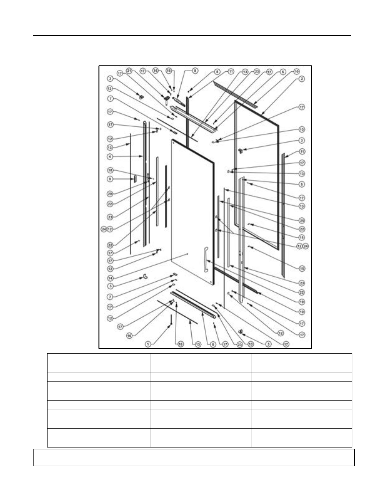
Description
Description
Description
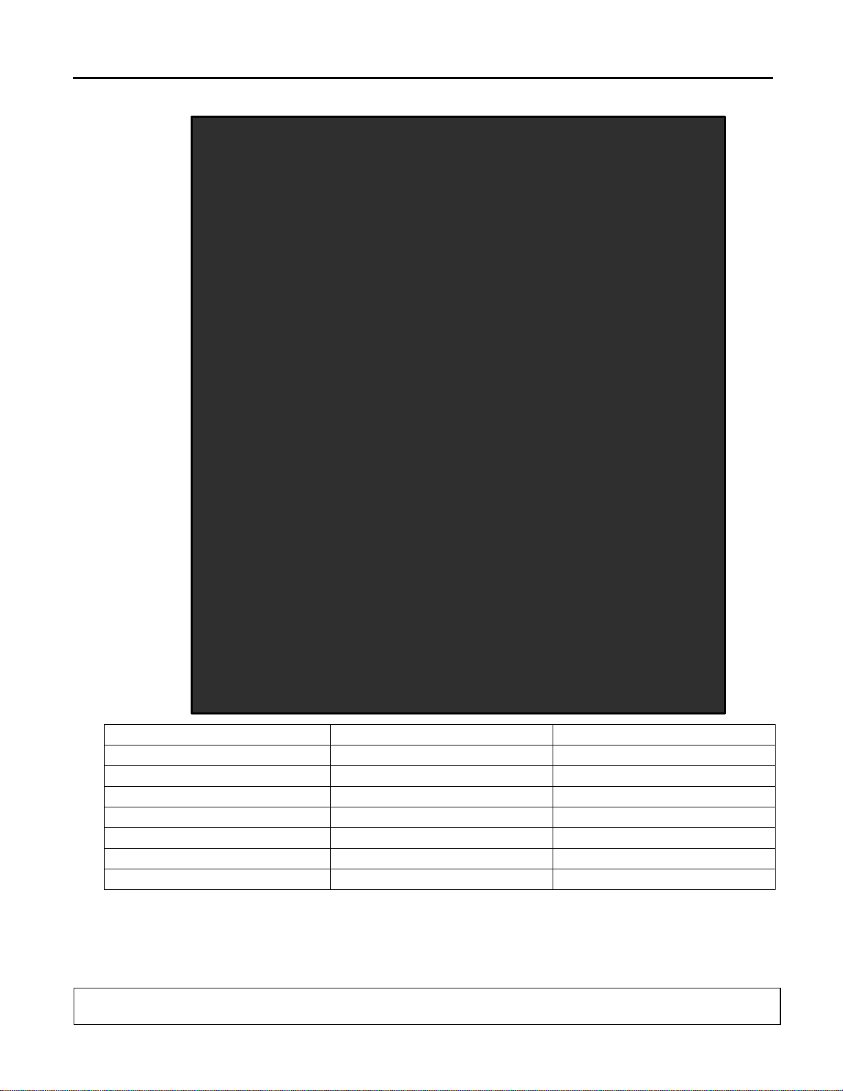
1. Torque Rod Assembly
10. Top & Bottom Rail Cover
19. Slimline Handle
2. Gasket with Magnet
11. Side Rail Covers
20. Ground Wire Assembly
3. Corner Pieces
12. Wedge Spacer
21. Hinge Pin
4. Door rail (Hinge Side)
13. Vinyl Glazing
22. Sealant
5. Door Rail (Handle Side)
14. Glass Pack Assembly
23. Foam Mounting Tape
6. Top & Bottom Rail
15. 10-28 x 5/8” Screws
24. 3M Hot Melt Sealant
7. Hold Open Backing Plate
16. 3/16” x 3/8” x 3/8” Rivets
25. Door Handle Rail Insert
8. Hold Open Fork & Spacer
17. 8-32 x 5/8” Screws
9. Access Hole Cover
18. #42 Steel Rivets
2. PARTS REPLACEMENT
2.1. Model 101B & ELM Door Parts Placement
99-16105-S001 – 101B, 210X, ELM, 101X Frame Installation & ServiceManual
TITLE:
REV.
C
Page 7 of 92
101B, 210X, ELM, 101X Frame Installation & Service Manual
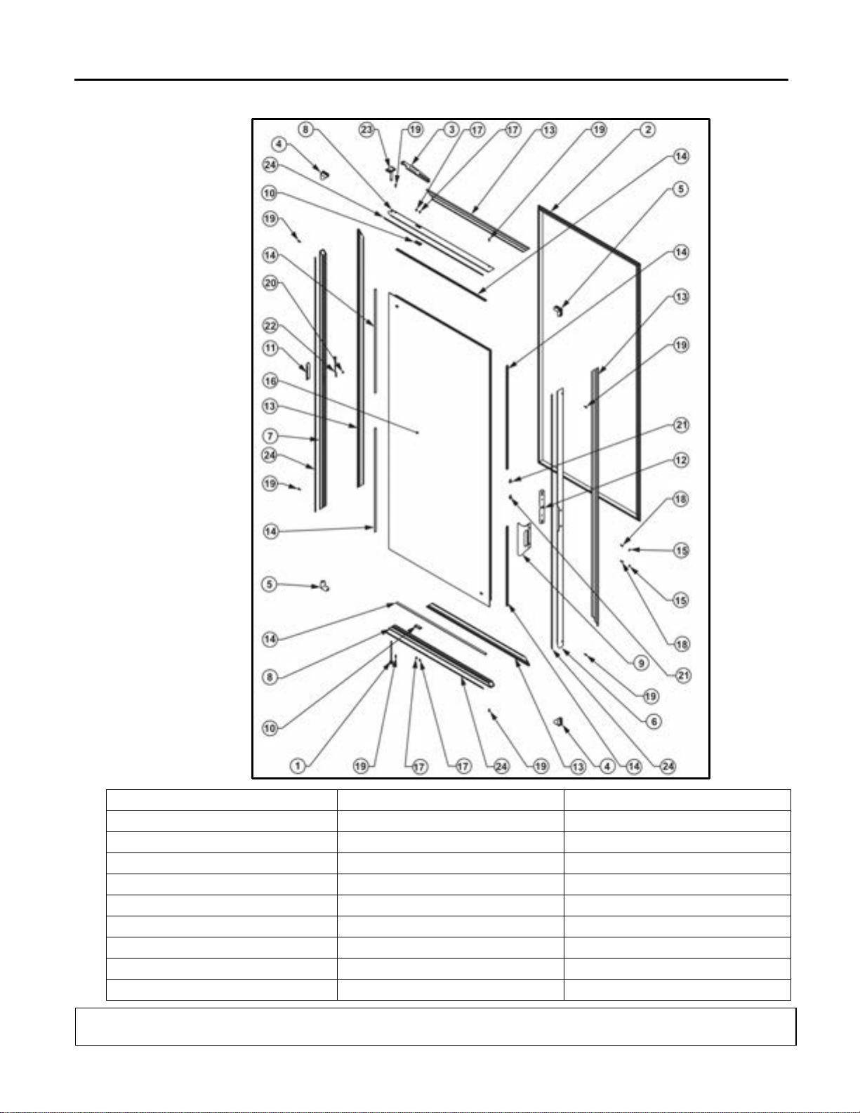
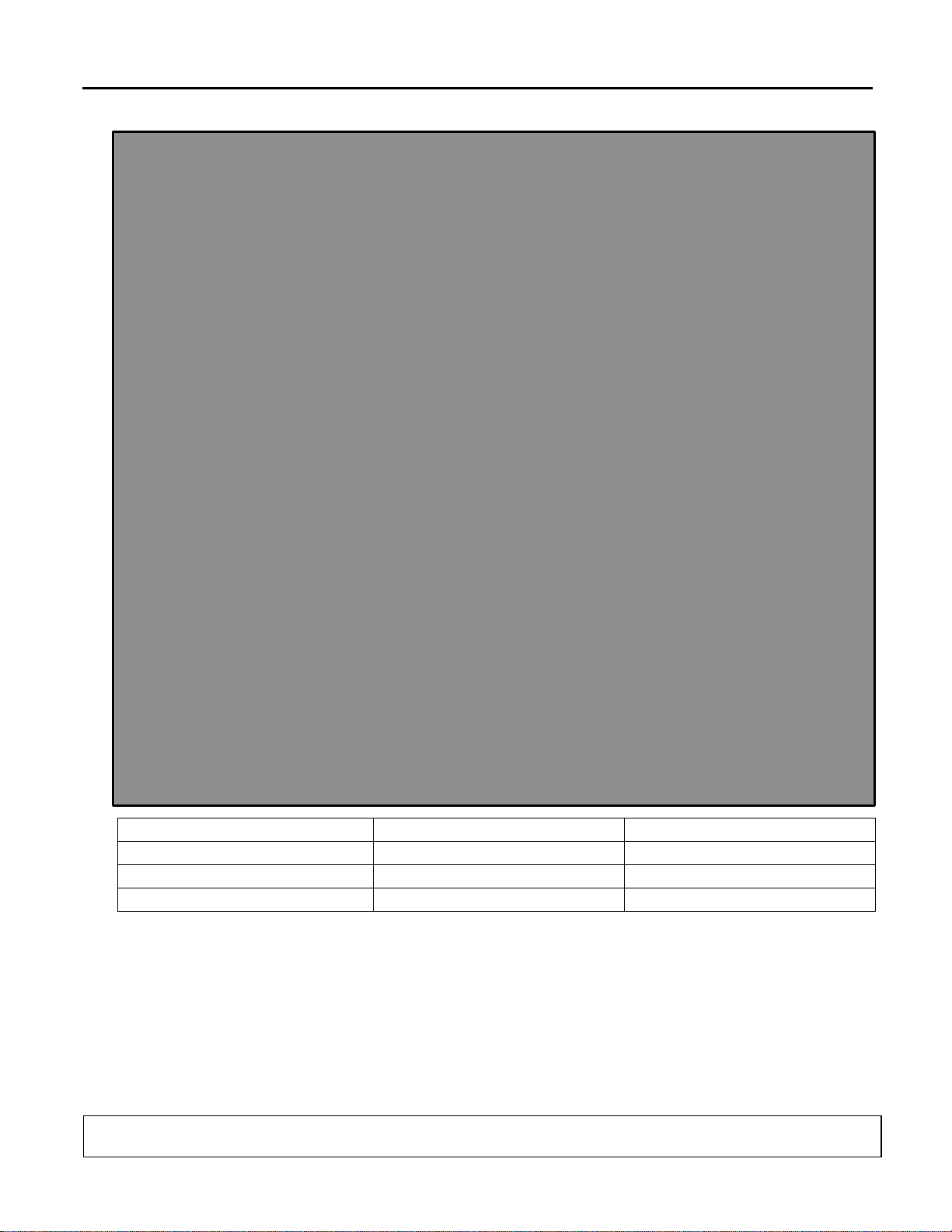
Description
Description
Description
1. Torque Rod Assembly
10. Plate Backing
19. 8-32 x 5/8” Black Screw
2. Gasket with Magnet
11. Access Hole Cover
20. 6-32 x 3/16” Screw
3. Hold Open Fork
12. Handle Mounting Bloc k
21. Weld Nut
4. Left Hand Corner Piece
13. Plastic Cover
22. Heater Wire Plug Assembly
5. Right Hand Corner Piece
14. Door Rail Filler
23. Hinge Pin
6. Handle Rail
15. Cap
24. Foam Tape
7. Hinge Rail
16. Door Glass Package
8. Top Rail
17. 3/16” x 3/8” Steel Rivet
9. Door Handle
18. 8-32 x 5/8” Zinc Screw
2.2. Model 210X Door Parts Placement
99-16105-S001 – 101B, 210X, ELM, 101X Frame Installation & ServiceManual
TITLE:
REV.
C
Page 8 of 92
Number of Doors Per Frame Section
1-Door
2-Door
3-Door
4-Door
5-Door
24”
23-3/16”
24-7/8”
48-5/8”
72-3/8”
96-1/8”
119-7/8”
26”
26-3/8”
28-1/16”
55”
81-15/16”
108-7/8”
135-13/16”
28”
28-3/8”
30-1/16”
59”
87-15/16”
116-7/8”
145-13/16”
30”
29-7/8”
31-9/16”
62”
92-7/16”
122-7/8”
153-5/16”
Number of Doors Per Frame Section
1-Door
2-Door
3-Door
4-Door
5-Door
24”
23-3/16”
25-1/8”
48-7/8”
72-5/8”
96-3/8”
120-1/8”
26”
26-3/8”
28-5/16”
55-1/4”
82-3/16”
109-1/8”
136-1/16”
28”
28-3/8”
30-5/16”
59-1/4”
88-3/16”
117-1/8”
146-1/16”
30”
29-7/8”
31-13/16”
62-1/4”
92-11/16”
123-1/8”
153-9/16”
2.3. Frame Width Data
2.3.1. Model 101X, 210X, ELM
101B, 210X, ELM, 101X Frame Installation & Service Manual
Catalog
Size
Actual
Door Size
Finished Frame Net Opening Width – Endless Mullion
Catalog
Size
Actual
Door Size
Finished Frame Net Opening Width – Full Flange
2.3.2. Single-Door thru Five-Door Full Flanged Frames
TITLE:
99-16105-S001 – 101B, 210X, ELM, 101X Frame Installation & ServiceManual
REV.
C
Page 9 of 92
101B, 210X, ELM, 101X Frame Installation & Service Manual
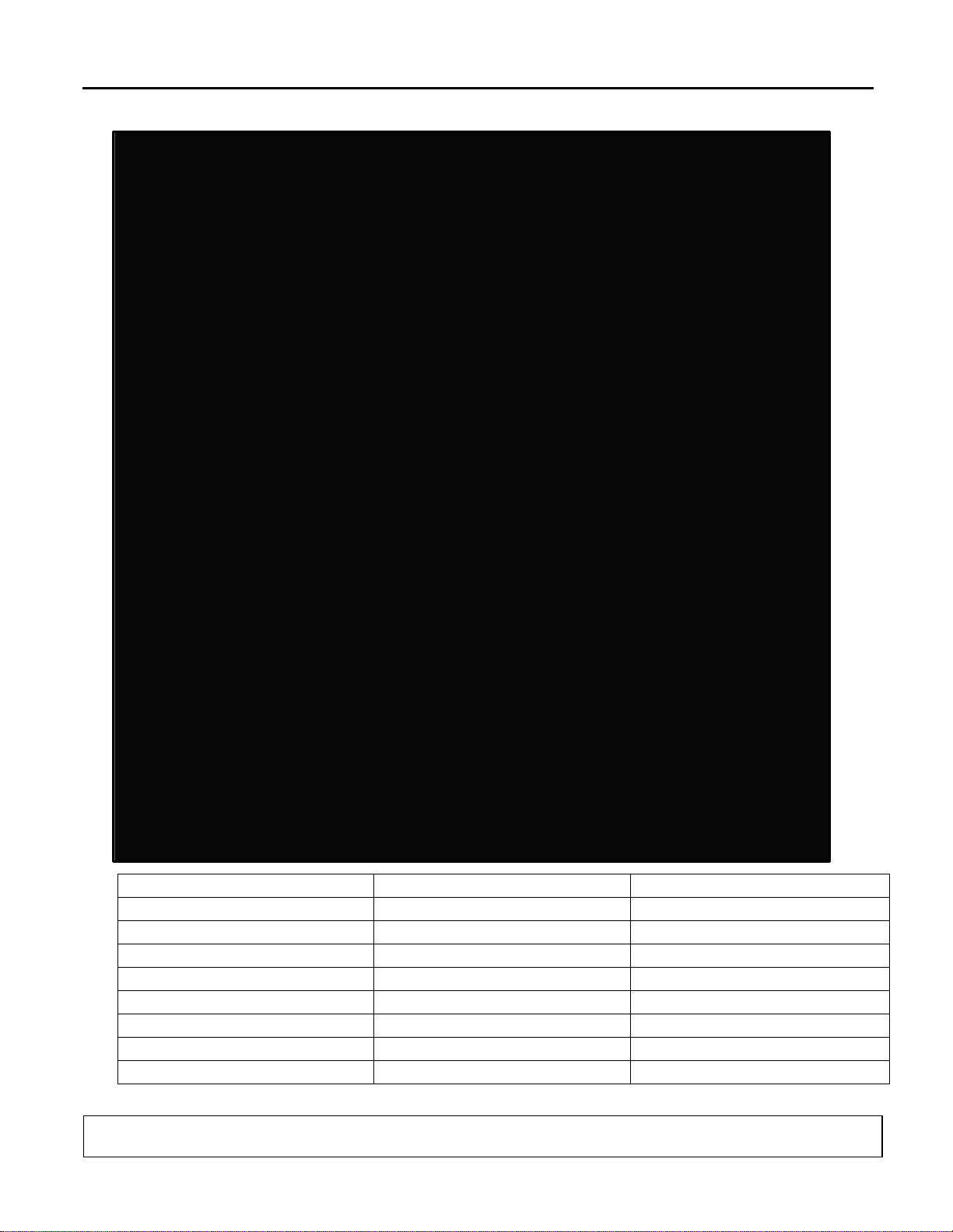
Description
Description
Description
1. Sill Frame
8. Flexible Aluminum Conduit
15. Hinge Pin Gib
2. End Frame
9. Heater & Lighting Wiring
16. Ground Jumper Assembly
3. Black Female Cap Plug
10. Screw-In Flexible Connector
17. 6-32 x 3/16” Screw
4. 8-18 x 0.219 SMS Screw
11. Flanged Frame Header
18. Center Mullion Contact Plate
5. Steel Lock Nut
12. Connection Diagram Label
19. End Frame Contact Plate
6. Warning & ID Labels
13. Brand Labels
20. Ballast
7. 90° Flex Connector
14. Warning Label
21. Bottom Contact Plate
2.4. Model 101X Frame Parts Placement
99-16105-S001 – 101B, 210X, ELM, 101X Frame Installation & ServiceManual
TITLE:
REV.
C
Page 10 of 92
101B, 210X, ELM, 101X Frame Installation & Service Manual
Description
Description
Description
1. Frame
4. Lamp Socket
7. Lamp Mounting Clip
2. Fluorescent Lamp
5. Rocker Switch (ELS Only)
8. Standard Lamp Cover
3. Center Mullion
6. On/Off Label (ELS Only)
9. Black Cloth Mounting Tape
2.4.1. Model 101X Frame Parts Placement Detail Diagram (Section A-A)
99-16105-S001 – 101B, 210X, ELM, 101X Frame Installation & ServiceManual
TITLE:
REV.
C
Page 11 of 92
101B, 210X, ELM, 101X Frame Installation & Service Manual
Description
Description
Description
10. 1/4-20 Cinch Nut
18. Mullion Lens Retainer Clip
26. ELS Frame Shelf Post Bracket
11. Frame End Lockstrike Support
19. Lens Assembly (End Jamb)
27. Swing Doors Lockstrike Plate
12. Torquemaster
20. Center Mullion Lens
28. Black Cloth Mounting Tape
13. Lamp Socket
21. End Frame Lens Retainer Clip
29. ELS Mullion Shelf Post Bracket
14. Perimeter End Cover
22. 18 x .219 Lampholder Screw
30. Std Mullion Shelf Post Brac ket
15. Socket Clip Mounting Screws
23. Heater Wire
31. 8-32 x 3/8 Taptite Screw
16. Bottom Backup Plate
24. ELS Exterior Contact Plate
32. 10-24 x 5/16 Tap 1 Screw
17. 3/16 x 11/16 Foam Tape
25. Sill Cover
33. Zipper Strip
2.4.2. Model 101X Frame Parts Placement Detail Diagram (Section B-B)
99-16105-S001 – 101B, 210X, ELM, 101X Frame Installation & ServiceManual
TITLE:
REV.
C
Page 12 of 92
101B, 210X, ELM, 101X Frame Installation & Service Manual
Description
Description
Description
34. Standard Lamp Socket
40. Mullion Shelf Bracket
46. Hold Open Stand-Off
35. Receptacle Mounting S c rew
41. Shelf Bracket Mounting Screw
47. Single Station Gib
36. Zipper Strip
42. Ballast
48. Dual Station Gib
37. 1/4 x 7/16 x .03 Flat Washer
43. Mullion Raceway Cover Plate
49. Single Hinge Pin Receptacle
38. Frame Raceway Cover Plate
44. Frame Extrusion
50. Dual Hinge Pin Receptacle
39. 1/4-20 x .375 Black Screw
45. 6-32 x 1 Socket Mount Screw
2.4.3. Model 101X Frame Parts Placement Detail Diagram (Section C-C)
99-16105-S001 – 101B, 210X, ELM, 101X Frame Installation & ServiceManual
TITLE:
REV.
C
Page 13 of 92

101B, 210X, ELM, 101X Frame Installation & Service Manual
2.5. Model 101X ELS Fluorescent Lamp Assemblies
TITLE:
99-16105-S001 – 101B, 210X, ELM, 101X Frame Installation & ServiceManual
REV.
C
Page 14 of 92
101B, 210X, ELM, 101X Frame Installation & Service Manual
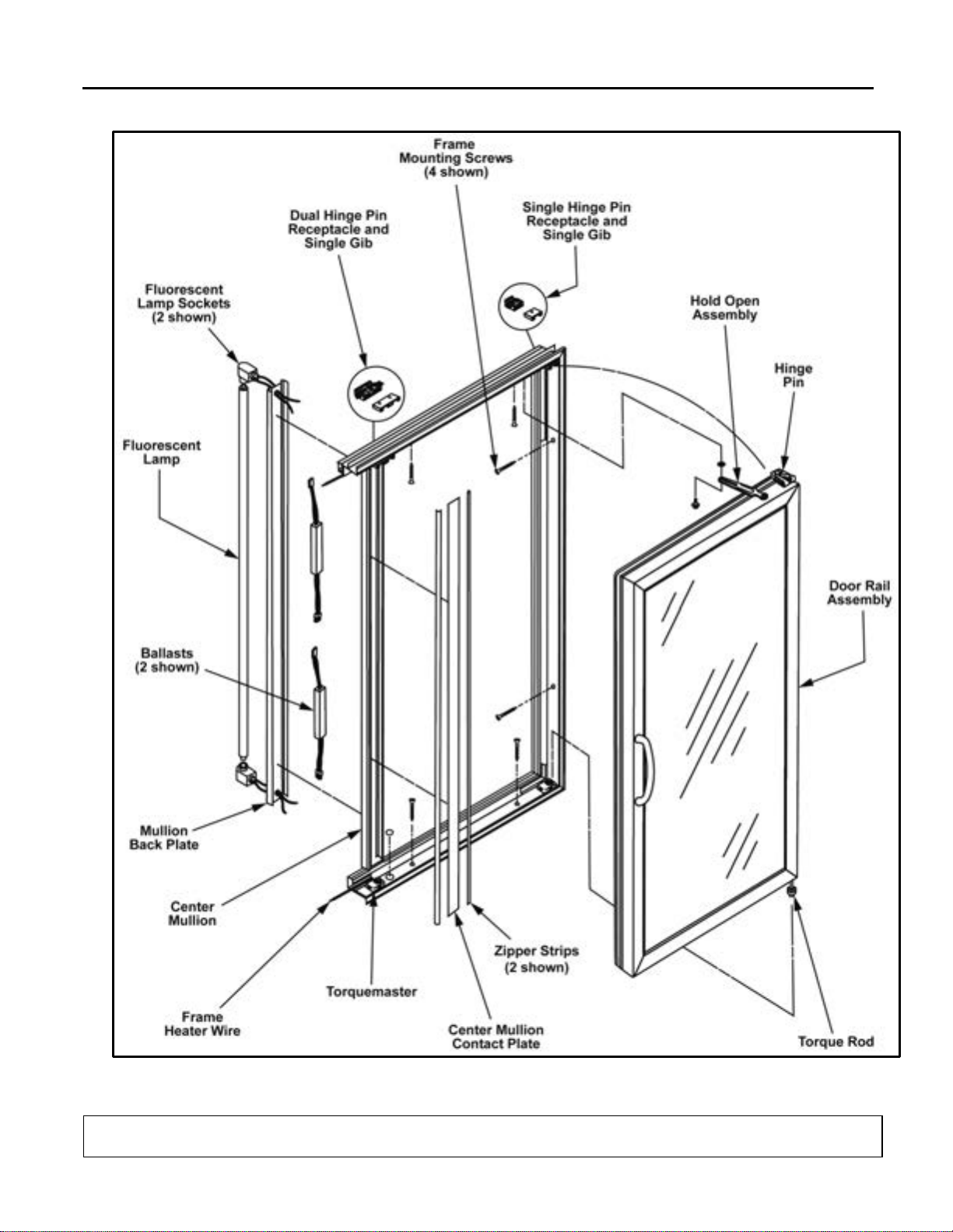
2.6. Door and Frame Assembly Diagram
TITLE:
99-16105-S001 – 101B, 210X, ELM, 101X Frame Installation & ServiceManual
REV.
C
Page 15 of 92
101B, 210X, ELM, 101X Frame Installation & Service Manual
3. DOOR REMOVAL AND REVERSAL
3.1. Removing the Door Assembly from the 101X Frame
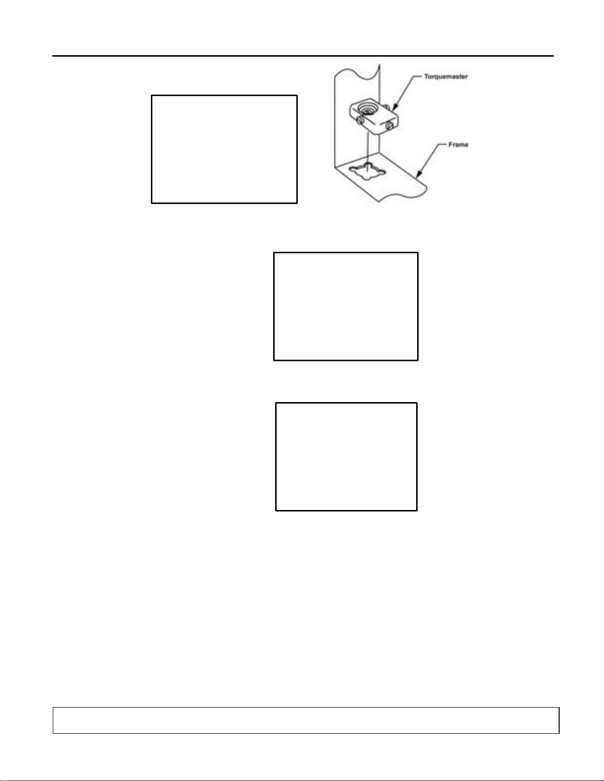
1. Using a flat-head screwdriver, loosen the tension on the door by turning the adjustment screw, located on the front of the torquemaster, to the right or clockwise.
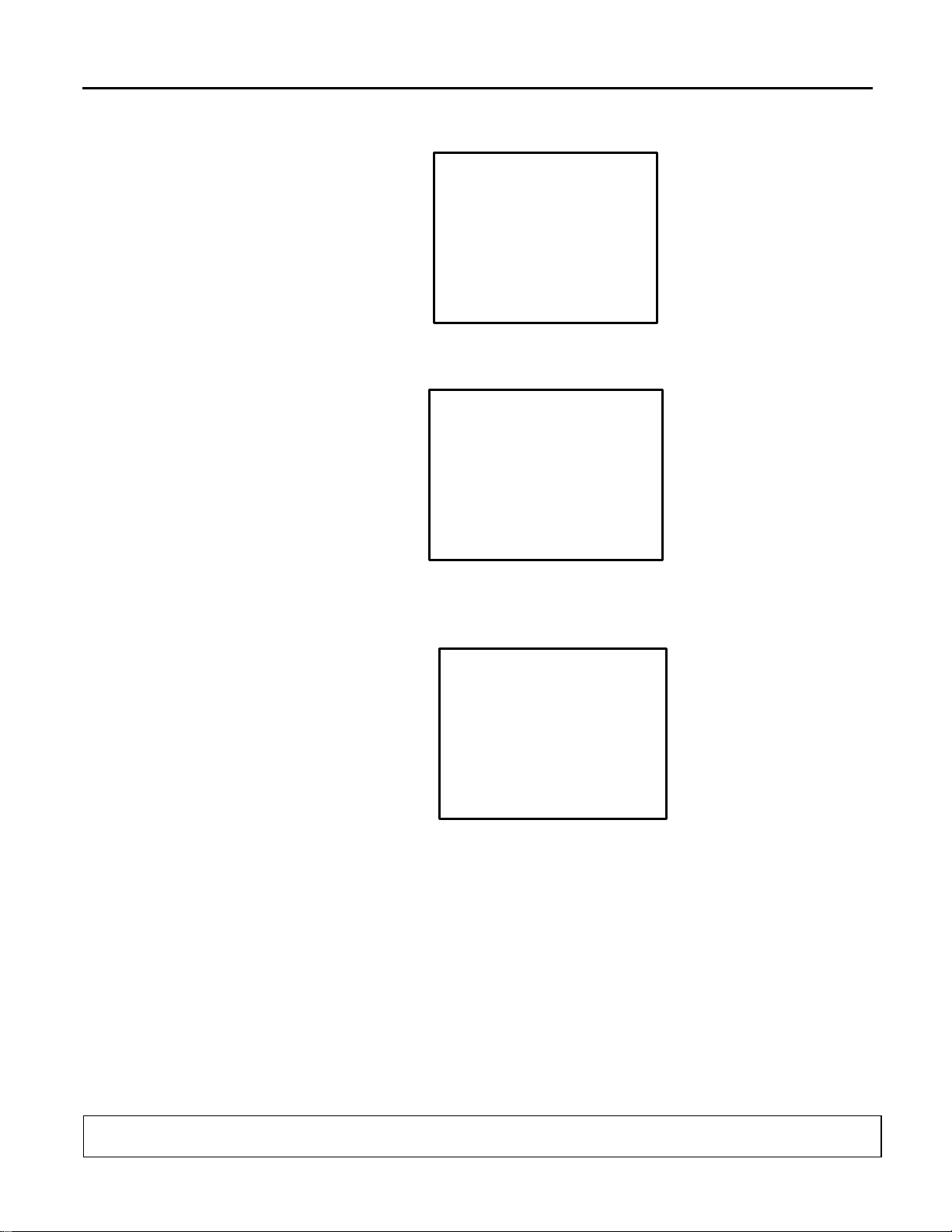
2. Test the door by opening it, and confirm that the torque tension does not retract the door from open positi on.
3. If tension remains, continue adjusting the torquemaster until all tension has been removed from the door.
4. Open the door to access the hold open device. Loosen and remove the holdopen bolt, using a phillips-head screwdriver.
5. Remove the hold open stud using a 7/16” hand w renc h.
6. Retract the door to a near-c l osed pos it ion.
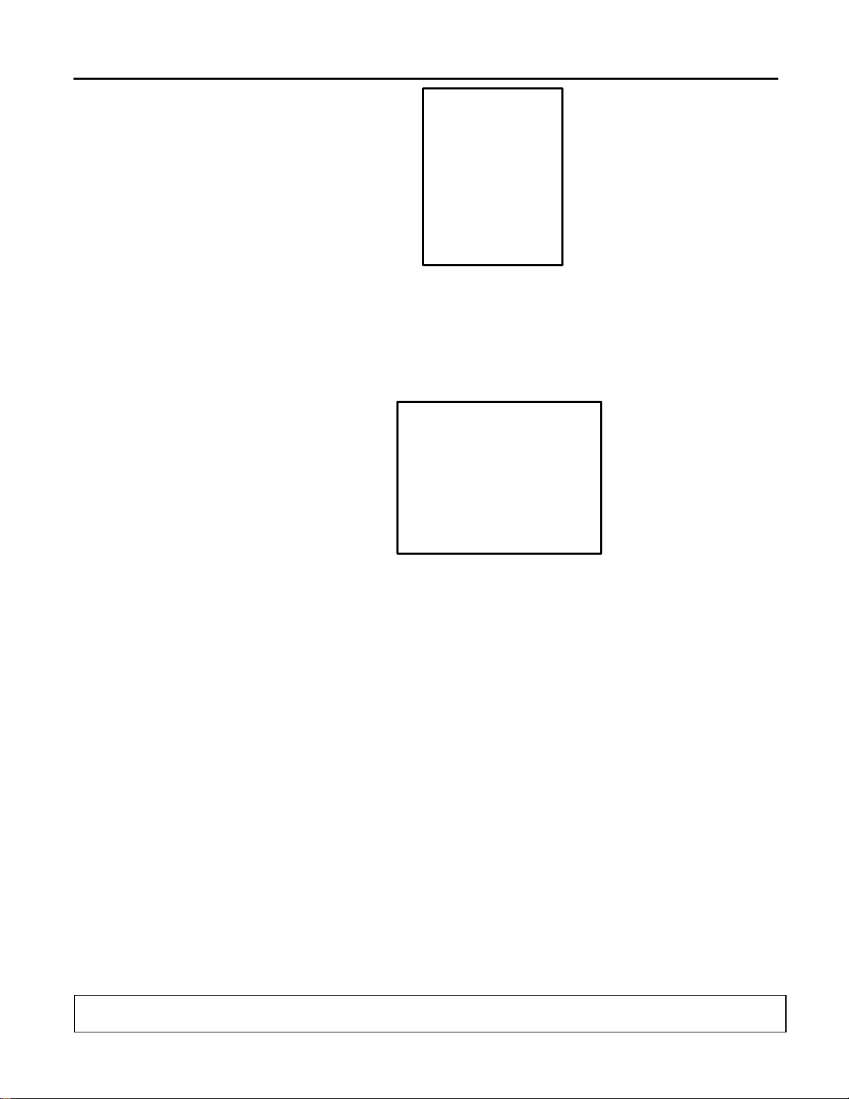
7. Insert the top hal f of the needl e-nose pliers into the grip-hole, located in the hinge
pin spring-clip, and the bottom half of the pliers beneath the hinge pin shroud.
TITLE:
99-16105-S001 – 101B, 210X, ELM, 101X Frame Installation & ServiceManual
REV.
C
Page 16 of 92
101B, 210X, ELM, 101X Frame Installation & Service Manual
8. Squeeze the pliers to clamp down on the hinge pin spring clip, allowing the clip to
release the hinge pin from the receptacle gib of the frame, while simultaneously
pulling the top of the door away from the frame. This will release and pull the hinge
pin out of the hinge pin receptacle and gib.
9. Continue pulling the top of the door assembly away from the frame until the top door
rail clears the frame.
10. Lift and remove the door from the torquemaster and carefully set the door aside.
3.2. Reversing the Door Swing
1. Using a flat-head screwdriver, loosen the torquemaster from its mount by turning the
center mounting screw counter-clockwise less than one-half (1/2) of a turn.
Remove the Torquemaster, exposing the mounting hole in the bottom frame rail.
TITLE:
99-16105-S001 – 101B, 210X, ELM, 101X Frame Installation & ServiceManual
REV.
C
Page 17 of 92
101B, 210X, ELM, 101X Frame Installation & Service Manual
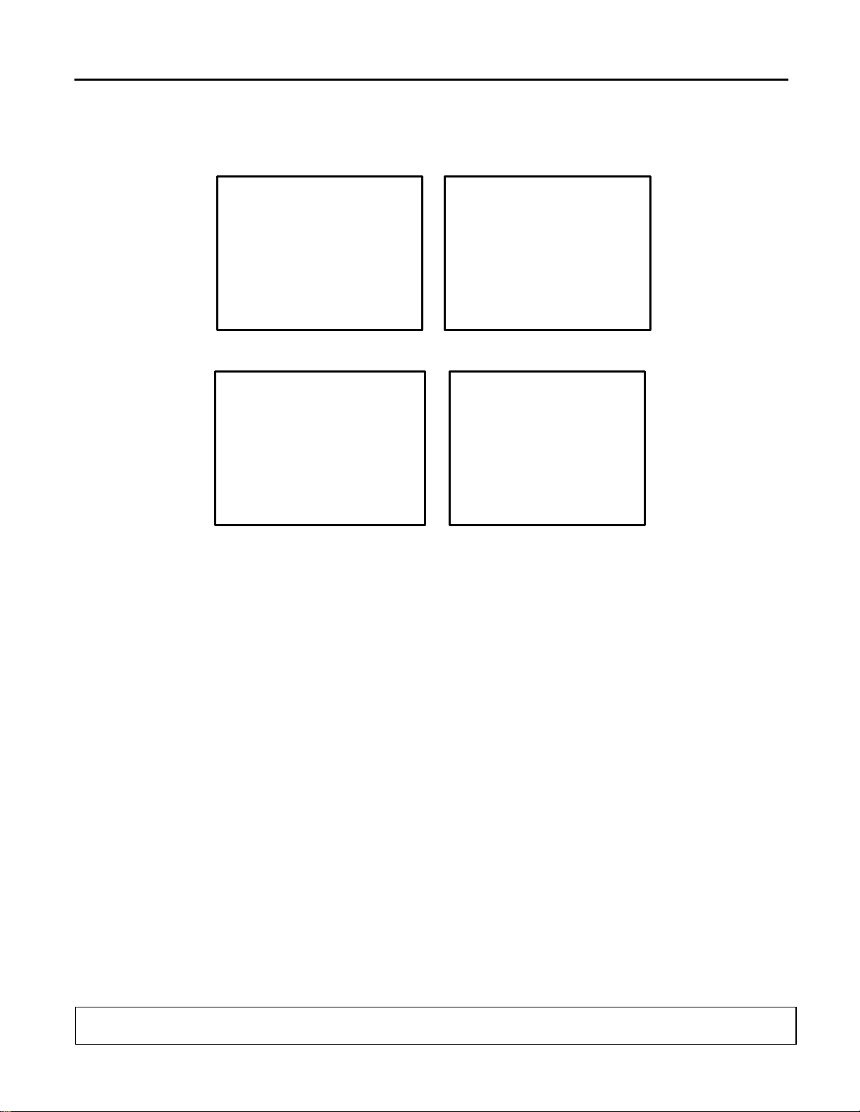
2. Locate the mounting hole at the opposite side of the door opening.
3. Using the flat-head screwdriver, carefully pry underneath the plug cap and remove it.
4. Place the Torq uemas t er on the newly opened mounting hole, aligning the flanged
corners of the mounting tabs.
5. Insert the Torquemaster mounting tabs onto the mounting hole with the hollow end
of the Torquemaster against the door frame.
6. Confirm that the mounting flanges on the bottom of the torquemaster align with the
corner mounting slots of the mounting hole in the frame.
7. Using a flat-head screwdriver, turn the Torquemaster mounting set-screw clockwise,
for 1/2 a turn, to tighten the mount and lock it in place. Confirm that the torquemaster
mounting is flush with the door frame.
TITLE:
99-16105-S001 – 101B, 210X, ELM, 101X Frame Installation & ServiceManual
REV.
C
Page 18 of 92
101B, 210X, ELM, 101X Frame Installation & Service Manual
8. Using a 7/16” open-ended hand wrench, loosen and remove the hold-open detent
bolt from the top frame rail.
9. Relocate and install the hold-open shoulder bolts into the opposite hold-open mount
of the same door frame.
10. If installing in Reverse Geometry, insert the hold-open stand-off into the fram e
header and install the detent bolt into the top of the door. Tighten each with a 7/16”
open-ended hand wrench.
11. Open the access portal to the hinge pin wire connections in the rail on the hinge
side of the door assembly.
12. Disconnect the Hot, Neutral and Ground wires of the hinge pin from the heater wire
circuit and the ground ter minal .
TITLE:
99-16105-S001 – 101B, 210X, ELM, 101X Frame Installation & ServiceManual
REV.
C
Page 19 of 92
101B, 210X, ELM, 101X Frame Installation & Service Manual
13. Loosen and completely remove the hinge pin assembly from the top door rail.
NOTE: Refer to “Removing and Replacing the Hinge Pin” for complete replacement
procedures.
14. Usi ng a plastic mal let and a fla t-head screwdriver, remove the torque rod from
the bottom of the door assembly.
NOTE: Refer to “Removing and Replacing the Torque Rod” for complete Torque Rod
replacement instructions.
15. Swap placement of the Hinge Pin and Torque Rod to the other’s original
mounting hole in the door assembly hinge side rail.
16. Reinstall the hinge pin and the torque rod completely into the ends of the door
assembly hinge rail.
17. If necessary, lightly tap on the hinge pin and torque rod with a plastic or rubber
mallet until each is fully seated into the top and bottom of the door.
18. Reconnect the hinge in wires and confirm that all connections are secure.
19. Check and confirm torque rod and hinge pin are correctly and completely
installed.
20. Reinstall the door into the frame.
NOTE: Refer to “REPLACMENT DOOR INSTALLATION” for complete door
installation instructions.
TITLE:
99-16105-S001 – 101B, 210X, ELM, 101X Frame Installation & ServiceManual
REV.
C
Page 20 of 92
101B, 210X, ELM, 101X Frame Installation & Service Manual
4. DOOR MAINTENANCE AND PARTS REPL ACEMENT
4.1. Removing and Replacing the Door Gasket
1. Begin removing the door gasket by lifting one corner of the gasket out of the groove.
2. Carefully pull the gasket out of the grove in the plastic rail covers.
NOTE: The gasket is composed of soft materials with welded miter joints. Use extra care
when manually extracting the gasket from the rail grooves to prevent damaging it as
well as the plastic rail.
3. Align the two corners of the replacement gasket onto the top mitered corners of the
plastic cover, with the gasket arrow facing the door rail and cover.
4. Press the gasket arrow into the groove in the center of the plastic cover corners until
the edges of the gasket arrow catch and the arrow is initially inserted into the groove
of the plastic cover.
5. Align the bottom two gasket corners with the bottom mitered corners of the plastic
covers, aligning the gasket arrow with the groove in the plastic cover and press the
corners into the groove until the arrow is fully inserted.
6. Press the gasket firmly against the top plastic cover, sliding from side to side and
applying full pressure against the gasket, forcing the gasket arrow into the groove in
the plastic top cover.
TITLE:
99-16105-S001 – 101B, 210X, ELM, 101X Frame Installation & ServiceManual
REV.
C
Page 21 of 92
101B, 210X, ELM, 101X Frame Installation & Service Manual
7. Continue pressing the gasket arrow into the grooves of the remaining p la st ic co ver,
around the entire door rail perimeter (if necessary, a plastic or rubber mallet can be
used to facilitate the arrow into the groove by applying a swift stroke onto the gasketDO NOT damage the gasket or the glass).
8. Confirm that the entire gasket arrow has been completely inserted into the groove of
all four plastic rail covers.
4.2. Removing and Replacing the Door Rail Plastic Cover
1. Insert the end of a slot head screwdriver in between two plastic cover ends at the
corner miter.
2. Carefully twist the screwdriver to loosen the corner of the plastic cover lip from the
door rail.
3. Continue to pry the plastic cover from the door rail until the entire end of the plastic
rail is disengaged.
TITLE:
99-16105-S001 – 101B, 210X, ELM, 101X Frame Installation & ServiceManual
REV.
C
Page 22 of 92

101B, 210X, ELM, 101X Frame Installation & Service Manual
4. Pull the plastic cover up and out of door rail grooves until the entire plastic cover is
removed from the door rail.
5. Repeat step 2 through st ep 4 to loosen and remove the three remaining plastic
covers.
6. To install the new, replacement plastic covers, begin by aligning the replacement
plastic cover evenly onto the door rail.
7. Insert the outer edge of the plastic cover into the outside groove of one of the door
rails.
8. Push the plastic cover down and inward, toward the center of the door.
9. Slide along the entire length of the plastic cover while firmly applying pressure
against it. Continue applying pressure along the length of the entire door rail,
inserting both the outside lip and the inside lip into the door rail grooves
simultaneously.
NOTE: Carefully tap the plastic cover with deliberate strokes, using a plastic or rubber
mallet outward and away from the glass. This may help seat the lips of the
plastic cover into the grooves of the door rails.
10. Check the entire plastic cover and confirm that both the inside and outside lips are
fully inserted into the door rail grooves.
11. Repeat this procedure, aligning each mitered corner, with the remaining plastic
covers until all four plastic covers are properly installed onto door rails.
12. Confirm that each plastic cover is fully installed and the mitered corners properly
aligned.
TITLE:
99-16105-S001 – 101B, 210X, ELM, 101X Frame Installation & ServiceManual
REV.
C
Page 23 of 92
101B, 210X, ELM, 101X Frame Installation & Service Manual
4.3. Replacing the Door Handle
1. Carefully remove the door gasket installed into the plastic cover over the door rail in
which the door handle is installed (leaving the gasket on the remaining door rail
assembly for easy reassembly is recommended).
2. Insert the end of a slot head screwdriver in between two plastic cover ends at the
corner miter of the plastic cover over the door rail with the handle.
3. Twist the screwdriver to loosen the corner of the plastic cover lip from the door rail
grooves.
4. Pry the plastic cover from the handle side of the door rail until the entire end of the
plastic rail is disengaged and remove the entire plastic cover from the door rail with
the handle.
5. Insert a 5/32” hex key or Allen Wrench into the door rail openings and into the screw
head securing the door handle.
6. Turn the screw counter-clockwise to loosen and remove it.
NOTE: In the event that the screw heads are obstructed, refer to product notification
for instructions detailing the removal of the obstruction. Refer to “Appendix B-1:
DOC IN-0002 SUPPLEMENTAL HANDLE REPLACEMENT INSTRUCTIONS
instructions for more inf orma t ion.
TITLE:
99-16105-S001 – 101B, 210X, ELM, 101X Frame Installation & ServiceManual
REV.
C
Page 24 of 92
101B, 210X, ELM, 101X Frame Installation & Service Manual
7. Repeat step 1 thru step 6 with the second mounting screw and remove the handle
assembly from the door.
8. Insert mounting scr ews into mounting holes until the ends of the screw protrude
through the mounting holes .
9. Insert the hex key or Allen Wrench into screw head.
10. Hold the Handle mounting holes against the protruding screw ends.
NOTE: Make sure the handle is configured with the screws mated with the correct
mounting holes in the handl e.
11. Turn the first screw clockwise until the threads catch.
12. Repeat the last step to connect the remaining screw and handle mount.
13. Tighten each mounting screw.
14. Confirm the handle is secure and flush-mounted to the surface of the door rail and
reassemble the door.
TITLE:
99-16105-S001 – 101B, 210X, ELM, 101X Frame Installation & ServiceManual
REV.
C
Page 25 of 92

101B, 210X, ELM, 101X Frame Installation & Service Manual
4.4. Door Bumper Removal and Replacement
1. Using a phillips-head screwdriver, loosen and remove both self-threading screws
and washers at each end of the bumper assembly. Remove the bumper (leaving the
gasket on the remaining door rail assembly for easy reassembly).
2. If necessary, remove bumper mounting brackets.
• Remove plastic covers from the longer, side door rails.
• Using a razor knife, carefully cut the silicone adhesive.
• Loosen and remove bracket mounting screws.
• Carefully remove mounting brackets.
3. Replace door bumper assembly mounting brackets.
• Completely clean each bracket of silicone adhesive residue.
• Apply a generous amount of fresh silicone adhesive to the outside of each
mounting bracket.
• Insert new self-threading 10-32 X 3/8” screws into the bracket mounting holes
and into the door rail mounting
• holes.
• Using a phillips-head screwdriver, turn the screws clockwise until all four
screws are tightened and both mounting brackets are securely fastened.
• Apply silicone adhesive along the seams of each bracket to ensure a proper
seal.
• Allow for silicone adhesive to fully cure.
TITLE:
99-16105-S001 – 101B, 210X, ELM, 101X Frame Installation & ServiceManual
REV.
C
Page 26 of 92

101B, 210X, ELM, 101X Frame Installation & Service Manual
4. Replace the plastic covers to the door rails (refer to plastic cover replacement
procedures).
5. Replace bumper assembly to the door.
6. Align the mounting holes in the bumper assembly with the holes in the mounting
brackets.
7. Insert new self threading 10-32 x 3/8” screws into the bumper assembly mounting
holes.
8. Using a phillips-head screwdriver, turn the screws clockwise until each screw is tight
and the bumper assembly is securely mounted.
9. Confirm that the bumper assembly is securely mounted to the door.
4.5. Cylinder Lock Repair and Replacement
1. Remove gasket from door rail containing the lock (leaving the gasket on the
remaining door rail assembly for easy reassembly).
2. Remove plastic cover from the door rail containing the lock assembly to expose
access to the lock mount.
TITLE:
99-16105-S001 – 101B, 210X, ELM, 101X Frame Installation & ServiceManual
REV.
C
Page 27 of 92
101B, 210X, ELM, 101X Frame Installation & Service Manual
3. Insert a large phillips-head screwdriver into the lock access in the back of the door
rail.
NOTE: Once the lock screw has been removed, the screw washers and lock latch will
come loose. Be certain that these components are secure prior to the removal
of the lock screw, or they may become lost if dropped inside of the door rail.
4. Turn the lock screw counter-clockwise to loosen the screw.
5. Carefully remove the screw, lock washers and lock strike from the back of the lock
assembly.
6. If necessary, replace the strike.
7. Remove the lock assembly, out from the lock housing and through the front of the
door rail.
8. Replace lock assembly into housing inside rail.
9. Replace the strike washer, strike, lock washer and screw to the rear of the lock
assembly and assemble in the correct order. Be certain that the strike is fully and
correctly seated onto the end of the cylinder.
TITLE:
99-16105-S001 – 101B, 210X, ELM, 101X Frame Installation & ServiceManual
REV.
C
Page 28 of 92
 Loading...