

Page 1
XM-100 Commercial
XM Satellite Radio
Owner’s Manual
Page 2

XM-100 Commercial Satellite Audio Receiver 2
Welcome! ........................................................................... 5
Installing XM-100 ................................................................ 5
Parts List ...................................................................... 6
Connections .................................................................. 6
Positioning the Antenna .................................................. 7
Optimizing Signal Strength ................................................... 9
Activating the XM-100 ........................................................ 10
Operating the XM-100 ........................................................ 10
Display and Indicators .................................................. 11
Tuning Modes .............................................................. 12
Changing Channels ...................................................... 12
Changing Categories .................................................... 13
Setting and Recalling Presets ......................................... 13
Setting Options Via Menus .................................................. 14
Navigating Setup Menus ............................................... 14
Signal Quality .............................................................. 16
Line Level ................................................................... 16
Front Lock ................................................................... 17
Time Zone .................................................................. 17
Daylight Savings Observation ........................................ 18
Channel Blocking ......................................................... 19
Channel Skipping ......................................................... 20
Forced Tuning .............................................................. 20
Using the Remote Control ................................................... 25
Integration with Distributed Audio Control Systems ............... 26
Technical Assistance .......................................................... 26
12 Month Limited Warranty ................................................. 26
Page 3

XM-100 Commercial Satellite Audio Receiver 3
Antex Electronics Corporation
19160 Van Ness Avenue
Torrance, California 90501
www.antex.com
Copyright © 2005 Antex Electronics Corporation. All Rights Reserved. No portion
of this manual may be reproduced without prior written consent from Antex
Electronics. Part number 9000-2480-7006 Rev A.
FCC Compliance Statement for United States Users
This equipment has been tested and found to comply with the limits for a Class B
device, pursuant to Part 15 of the FCC Rules. In order to maintain compliance
with FCC regulations, shielded cables must be used with this equipment.
Operation with non-approved equipment or unshielded cables is likely to result in
interference to radio and TV reception. Changes or modifications made to this
equipment not expressly approved by Antex Electronics could void the user’s
authority to operate the equipment.
IMPORTANT SAFETY INSTRUCTIONS
Read Instructions – Read all Safety Instructions before operating equipment.
Retain Instructions – Save these instructions for future reference.
Heed Warnings – All warnings and these instructions should be adhered to.
Follow Instructions – All operating and use instructions should be followed.
Cleaning –Do not use liquid or aerosol cleaners. Use a damp cloth for
cleaning.
Attachments – Do not use attachments not recommended by the
manufacturer as they may cause hazards.
Water and Moisture – Do not use this product near water – for example near
a bathtub, wash bowl, kitchen sink or a room where moisture is likely to
occur.
Accessories – Do not place on an unstable surface (cart table or tripod) where
tipping is a possibility.
Ventilation – Install unit in well ventilated area where self generated heat
may escape. Bookcases or cabinets should have proper venting to allow heat
to escape.
Power outlet – A properly grounded wall outlet must be used. Do not use a
plug adapter that bypasses the three-terminal ground plug.
Power Cord Protection – Route your power cords out of traffics way so as not
to be walked on or traveled over by carts wheels. Do not place items on top
of or against the cord so as to pinch the cord.
Outdoor Antenna Grounding – The antenna and coaxial cable connecting to
the unit must be properly grounded to provide some protection against
voltage surges and built-up static charges. Article 810 of the National
Electrical Code, ANSI/NFPA 70, provides information with regard to proper
grounding of the mast and supporting structure, grounding of the lead-in wire
to an antenna discharge unit, size of grounding conductors, location of
antenna-discharge unit, connection to grounding electrodes, and
requirements for the grounding electrode.
Page 4

XM-100 Commercial Satellite Audio Receiver 4
Power Lines – An outside antenna system should not be located in the vicinity
of overhead power lines or electric light or power circuits, or where they can
fall into such power lines or circuits. When installing an outside antenna
system, extreme care should be taken to keep from touching such power lines
or circuits as contact with them might be fatal.
Overloading – Do not overload wall outlets, extension cords, or integral
convenience receptacles as this can result in a risk of fire or electrical shock.
Object and Liquid Entry – Never push objects of any kind into this product
through openings as they may short-out parts that could cause a fire. Never
spill liquid of any kind on the product.
Servicing – Do not attempt to service this product yourself; there are no
customer serviceable parts inside. Refer all servicing to qualified service
personnel.
A product and cart combination should be moved with care. Quick stops,
excessive force, and uneven surfaces may cause the product and cart
combination to overturn.
Damage Requiring Service – Unplug this product from the wall outlet and
refer servicing to a qualified service person under the following conditions:
a) When the power-supply cord or plug is damaged.
b) If liquid has been spilled, or objects have fallen into the product.
c) If product has been exposed to rain or water.
d) If the product does not operate normally by following the operating
instructions. Adjust only those controls that are covered by the operating
instructions as an improper adjustment of other controls may result in
damage and will often require extensive work by a qualified technician to
restore the product to its normal operation.
e) If the product has been dropped or damaged in any way.
f) When the product exhibits a distinct change in performance – this
indicates a need for service.
Replacement Parts – When replacement parts are required, be sure the
service technician has used replacement parts specified by the manufacturer
or have the same characteristics as the original part. Unauthorized
substitutions may result in fire, shock, or other hazards.
Safety Check – Upon completion of any service or repairs to this product, ask
the service technician to perform safety checks to determine that the product
is in proper operating condition.
Heat – The product shall be situated away sources such as radiators, heat
resistors, heat registers, stoves, or amplifier that produce heat.
Technology - It is prohibited to copy, decompile, disassemble, reverse
engineer, or manipulate any technology incorporated in receivers compatible
with the XM Satellite Radio system. Furthermore, the AMBE (R) voice
compression software included in this product is protected by intellectual
property rights including patent rights, copyrights, and trade secrets of Digital
Voice Systems, Inc. The user of this or any other software contained in an XM
Radio is explicitly prohibited from attempting to copy, decompile, reverse
engineer, or disassemble the object code, or in any other way convert the
object code into human-readable form. The software is licensed solely for use
within this product.
Page 5

XM-100 Commercial Satellite Audio Receiver 5
Welcome!
Thank you for choosing the world’s finest high-fidelity,
commercial XM satellite radio receiver.
There’s a world beyond AM and FM. XM Satellite Radio. Over
150 channels of music, news, sports, comedy, talk, and
entertainment. Coast-to-coast coverage. Digital quality sound.
100% commercial-free music channels and the deepest playlist
in the industry with over 2 million titles. For an up-to-date
channel lineup, please visit www.xmradio.com.
Hardware and required basic monthly subscription sold
separately. Premium Channel available at additional monthly
cost. Installation costs and other fees and taxes, including a
one-time activation fee may apply. Subscription fee
is commercial only. All fees and programming subject to
change. Channels with frequent explicit language are indicated
with an XL. Channel blocking is available for XM radio receivers
by calling 1-800-XMRADIO. Subscriptions subject to Customer
Agreement available at xmradio.com. Only available in the 48
contiguous United States. XM® is a registered trademark of
XM Satellite Radio Inc. ©2005 XM Satellite Radio Inc. All rights
reserved. This unit requires a monthly subscription from
XM Satellite Radio. To subscribe, contact XM on the Web at
www.xmradio.com or by phone at 1-800-XM-RADIO (or
1-800-967-2346).
Installing XM-100
Antex Electronics recommends that the XM-100 unit and its
antenna be installed by a professional installer. Brief
instructions are presented here for reference purposes.
The installation process consists of three steps:
1. connecting the radio to audio equipment
2. positioning the satellite antenna
3. activating the radio
Page 6
XM-100 Commercial Satellite Audio Receiver 6
XM-100 unit
Antenna (Not Included)
Remote control
Power Adapter
RCA audio cable
RF IN is now
a female FConnector
RCA line level
audio out
3.5 mm line
level audio
out
RS232
control
port
DC power in
Parts List
Before installing your XM-100, make sure you have all the
parts listed below:
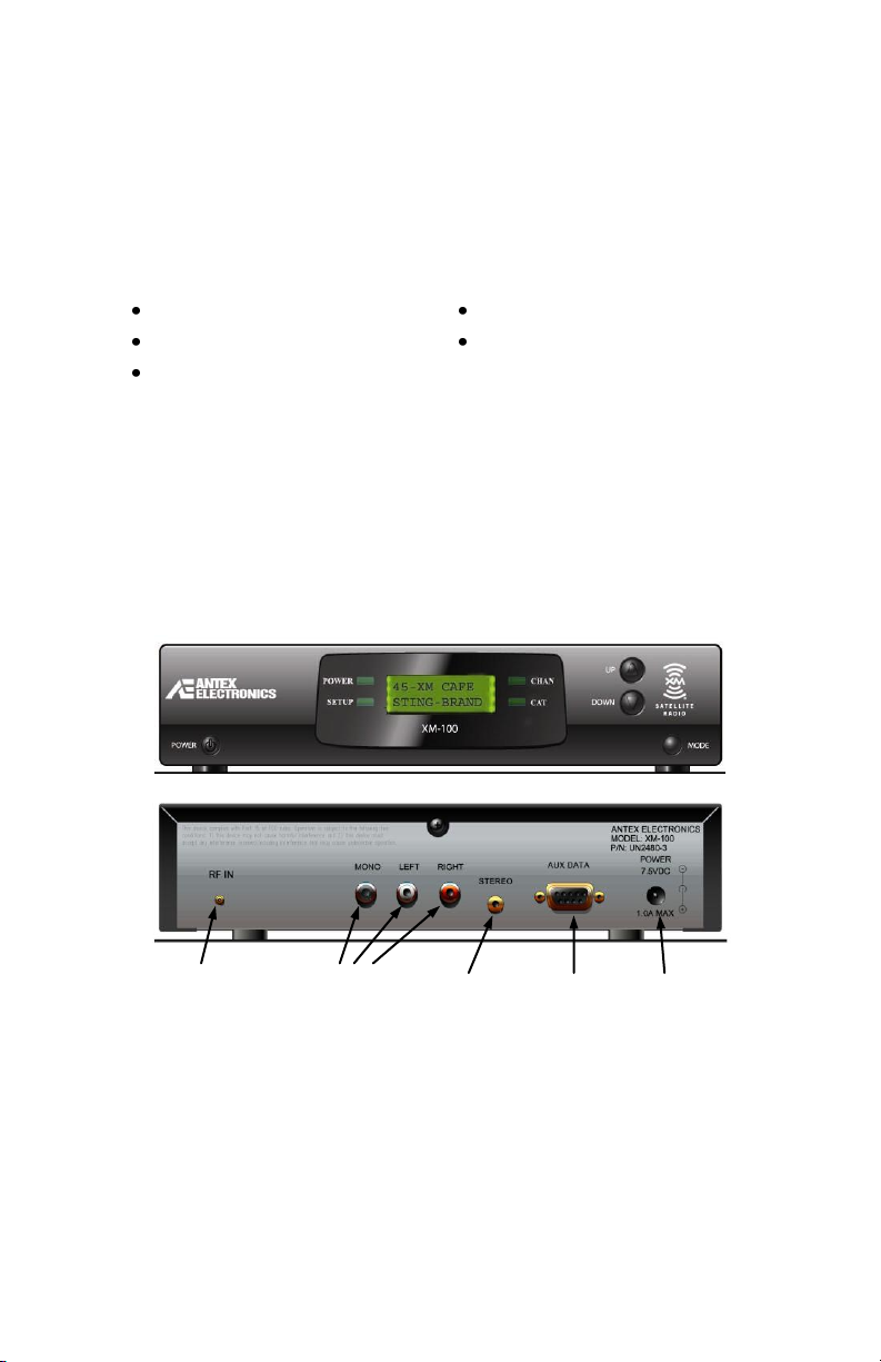
Connections
House the XM-100 unit in a component rack or other suitable
location that provides adequate ventilation. The maximum
ambient temperature should never exceed 120 degrees
Fahrenheit. The unit’s front user interface and various
connectors on the back of the unit are shown here:
Connect the XM-100 as follows:
1. Audio output – audio connection may be made to either
the RCA outputs or the 3.5mm output jack. These two
output connectors are internally wired in parallel, and it is
generally not recommended that both outputs be used
simultaneously unless it is known that both outputs drive a
high impedance load. The maximum level is 2VRMS.
Page 7

XM-100 Commercial Satellite Audio Receiver 7
2. Power in – connect only the included AC adapter to a
suitable 120VAC power source.
3. Antenna – As of February 2012, all XM-100 radios now
have a female F-connector (not pictured) for the antenna
input. Connect the XM antenna to the female F-Connector
on the XM-100 and position antenna as described in the
next section. Custom lengths of 50 ohm RG58U or existing
RG-6 cable may be used with extension kits available from
third party sources (see enclosed flier).
4. RS232 – an RS232 control port is provided for optional
control of the XM-100 unit from 3rd party control systems.
Antex recommends that this connection be used only by
experienced professional installers. Do not connect this
RS232 port to a computer – this connection is NOT
compatible with personal computers. See www.antex.com
for more information about using the RS232 control port.
Positioning the Antenna
The provided XM antenna requires exposure to the
south/southeastern sky for proper signal reception. To position
your antenna, first connect the XM-100 to your audio system
as described above, then follow these instructions.
1. Power on the receiver, verify the power indicator is
illuminated and the display backlight is on. If the message
―CHECK ANTENNA‖ appears, check that the antenna
connector is fully engaged, an open circuit does not exist
between the receiver and antenna, and that no short
circuit exists in the antenna cable. If the antenna does not
have a clear path to the satellites, the front panel display
will read ―NO SIGNAL‖.
2. Align the Antenna as follows:
For Indoor installation on a flat surface:
Page 8

XM-100 Commercial Satellite Audio Receiver 8
a) Set antenna on its base on a flat horizontal surface.
b) Turn the base of the antenna so that the XM logo is
facing to the south if you are in the eastern half of the
U.S. and to the south/southeast if you are in the
western half of the U.S.
c) Bring up the signal strength menu by holding down the
power button for 4 seconds and optimize signal
strength using the instructions in the next section. Exit
signal strength Mode by pressing the power button.
d) If necessary, experiment with different antenna
locations near a south-facing window or outside.
For Outdoor installation or indoor wall mounting:
The antenna can also be attached vertically to an external
or internal wall if that is more convenient than placing it on
a horizontal surface.
a) Holding your antenna up, find a wall location that
ensures a strong signal.
b) Attach antenna to the wall using four screws.
c) Tilt the antenna fully back on the base, place the
antenna base on the four screw heads with the
antenna pivot at the top, and pull down approximately
1/4 inch until the base is firmly secured. Note that the
XM logo will be upside down when the antenna is
properly installed.
d) Bring up the signal strength menu by holding down the
power button for 4 seconds and optimize signal
strength using the instructions in the next section. Tilt
the antenna away from the wall/base until the signal
strength is optimized. Exit signal strength Mode by
pressing the power button.
3. Power on your sound system and turn the amplifier to a
low volume.
4. If the system is working, you will hear XM programming on
channel 1 and can proceed to activating the XM-100.
If there is a problem with the antenna connection, the XM-
100’s front panel display will read ―Check Antenna.‖ If the
antenna does not have a clear path to the satellites, the
front panel display will read ―NO SIGNAL‖. Reposition the
Page 9

XM-100 Commercial Satellite Audio Receiver 9
CN1 CN2 TBER
9.0 8.5 12%
antenna until signal strength is optimized and you hear
audio.
5. Activate the unit following the ―Activating XM-100‖
instructions.
Optimizing Signal Strength
For robust operation, signal strength received from the
antenna must be optimized. Optimum alignment of the
antenna may be achieved using the signal strength menu.
Press and hold the power button for 4 seconds, a display
similar to below will appear.
CN1 and CN2 indicate the carrier to noise ratio of the satellite
signal received from the two XM satellites positioned in the
southern sky over the equator. The higher the number the
better, and both numbers should be 10 or greater for good
margin, but not less than 7.0.
TBER is the percentage of bit errors received from a terrestrial
repeater, if there is one. Acceptable values for this number
may be anywhere from 0% if a repeater is nearby, to 100% if
only the satellite signals are available – lower is better. The
audio mute threshold for the terrestrial signal is approximately
6% bit error rate.
Position and rotate the antenna for the optimum balance
(highest readings) for CN1 and CN2. Note that CN1 measures
signal received from the satellite in the Eastern sky, CN2 signal
received from the satellite in the Western sky. Obstructions
such as trees or tall buildings may interfere with reception of
one or more satellite signals and require that the antenna be
repositioned.
When complete, press the power button to return the display
to its normal operating Mode.
Page 10

XM-100 Commercial Satellite Audio Receiver 10
Activating the XM-100
After the channel 1 audio verification test, you must activate
your XM-100 to access all XM channels. Commercial accounts
must sign up for and activate under the terms of XM’s
Commercial Service.
To activate the radio you must first obtain the XM Radio ID
number of your unit. Tune the receiver to channel 0 by using
the down button on the unit’s front or press 0 on the remote
control. The 8 digit XM Radio ID will be displayed.
Record the 8 character ID in the space below, noting that
letters I, O, S and F are not used and that the number zero
has a line running diagonally through it.
XM Radio ID: _________________________
Activate your XM radio service by calling XM at 1-800-XMRADIO (1-800-967-2346). Commercial accounts cannot be
activated via the Internet. A friendly listener care
representative will assist you in activating your unit.
Customers should have their Radio ID ready; the Radio ID can
be found by selecting channel 0 on the radio.
Operating the XM-100
XM-100 provides intuitive control of its various functions via its
front panel buttons as shown on the next page, the remote
control, and the RS232 port (for local and remote operation).
Note that in the event of power loss, the radio will automatically
return to its state before power loss.
Basic operation allows the user to:
Change channels and music categories
Enter a channel number on the remote to tune to a channel
directly
Set and tune to preset channels via the remote control—10
presets total
You can also use the SETUP menu to set forced tuned events,
block specific channels, as well as add and skip channels.
Instructions for all these features are provided in later sections.
Page 11

XM-100 Commercial Satellite Audio Receiver 11
Display and Indicators
The default display, as shown below, provides information about
the channel currently tuned to, including channel number and
channel name on the first line and scrolling artist name and song
title on the second line.
The display backlight is illuminated and text appears after the
power button has been pressed, indicating the unit is on.
The XM-100 has four indicators and four buttons as follows
(Modes are described below):
Power Indicator – illuminated whenever power present
Setup Indicator – illuminated when in Setup Mode
CHAN Indicator – illuminated when in Channel Mode. Both
CHAN and CAT indicator illuminated in Channel/category
Mode.
CAT Indicator – illuminated when in Category Mode. Both
CHAN and CAT indicator illuminated in Channel/category
Mode.
Power Button – turns unit on/off. Hold for signal strength.
Press to exit setup menus.
Mode Button – cycles operational Mode of unit through
Channel, Category, Channel Category, or Setup. Holding for 4
seconds enters Setup Mode.
Up and Down Buttons – changes channels and used for menu
navigation.
Page 12

XM-100 Commercial Satellite Audio Receiver 12
Tuning Modes
The XM-100 supports three Modes of channel selection:
Channel (default), Category and Category/Channel. Examples
of categories are Rock, Classical, etc.
Channel Mode allows you to scroll through and select any
channel in the entire XM lineup regardless of what category
the channel belongs to. Channel Mode is the default Mode at
power up. When you switch to Category Mode, the unit will
scroll through the different Categories offered by XM.
Category/Channel Mode allow the user to scroll through
channels only within the current category. This is particularly
useful when, for example, if you want to listen to and scroll
through news channels only.
To cycle through the three tuning Modes, press the MODE
button. By default the unit is in Channel Mode and the CHAN
LED is illuminated. When you press the MODE button once, the
unit will enter Category Mode and the ―CAT‖ LED is illuminated
on the front panel. Press MODE again to enter
Category/Channel Mode (both CHAN and CAT LEDS are
illuminated) and again to return to CHAN Mode.
Changing Channels
You can change channels in either Channel or
Category/Channel Mode using three methods:
Channel up/down buttons
Direct channel entry using numbered buttons on the
remote
Preset button on the remote to tune to a preset channel
Use the up/down buttons on the front panel or remote to scroll
through channels. You will notice that the channel number and
name, artist name, and song title information in the display
change to reflect the new channel. Selection (and audio) of the
new channel occurs a couple seconds after you have finished
pushing the buttons.
You can also tune to a specific channel directly simply by
pressing in its channel number using the NUMERIC buttons on
Page 13

XM-100 Commercial Satellite Audio Receiver 13
SAVE 044 TO
PRESET NO.?
the remote. You may enter one, two, or three digits
representing a valid channel number.
When preset channels have been set, you can access those
presets simply by pressing the PRESET button on the remote,
then an appropriate numeric button. For example, if preset 0
were set to Rock, preset 1 to Hits, and preset 2 to News, you
could jump to the News channel quickly by pressing ―PRESET-2.‖
Changing Categories
The channels of the XM service are conveniently organized into
categories such as Hits, Rock, News, Sports, etc. To enter
Category Mode, press the ―MODE‖ button on the front panel to
illuminate the ―CAT‖ LED on the front panel. Alternatively,
press the CAT button on the remote control.
Press the up/down buttons to tune to a different category.
Note that the category name, channel number, artist name,
and song title information in the display change to reflect the
new category. A channel’s category may be displayed at any
time by entering Category Mode.
Setting and Recalling Presets
The XM-100 can store up to 10 channel presets (numbered 0
to 9). To assign a preset, first tune to a desired channel, in
this example 44. Then press and hold the PRESET button on
the remote for 4 seconds. The display will change to:
Press the numeric button you wish to assign this channel to
and it will be stored.
To recall a stored preset, press (but don’t hold) the PRESET
button. The display will indicate Preset? - simply select the
desired numeric button (0-9).
Page 14

XM-100 Commercial Satellite Audio Receiver 14
Setup Menus
Mode to Exit
Setting Options Via Menus
The XM-100 SETUP Mode allows you to configure options such
as forced tuning, blocking, skipping, etc.
To enter the SETUP Mode, press and hold the MODE button on
the front of the unit for 4 seconds or depress the SETUP button
on the remote. The Setup indicator illuminates, and the menu
shown below appears.
Navigating Setup Menus
The top level structure of the menu system is shown below
and indicates which parameters may be configured. In SETUP
Mode, the channel up/down buttons on the unit or remote
control are used to scroll though the menu options. The Mode
button or Setup button on the remote is used to descend to a
sub-menu, or to exit up to a higher level.
At the top level menu heading shown above, pressing the
Mode button on the unit or remote control exits to normal unit
operation. You must navigate back to this menu using the
up/down keys for the Mode button to exit back to normal
operation of the unit. To help avoid confusion, with few
exceptions (in sub menus of blocking or skipping), pressing the
power button on the unit or remote control will exit out of
Setup Mode and restore normal operation. If you feel stuck in
a submenu - press the power button to get out.
Page 15

XM-100 Commercial Satellite Audio Receiver 15
SETUP MENUS
MODE TO EXIT
SETUP
up
Wraps Around
SIGNAL QUAL
LINE LEVEL
up
SETUP
SETUP
FRONT LOCK
SETUP
TIME ZONE
SETUP
DLT SAVING
SETUP
CH BLOCKING
SETUP
CH SKIPPING
SETUP
FORCE TUNING
SETUP
SW VERSION
Page 16

XM-100 Commercial Satellite Audio Receiver 16
CN1 CN2 TBER
#.# #.# ###
Line Level
+9 2.00VRMS
Signal Quality
When Setup – Signal Quality is displayed, pressing the Mode
button brings up the following menu:
This menu may also be displayed by holding the power button
for 4 seconds when at the main display. Pressing the Mode
button returns up one menu level. Pressing the power button
exits the setup menus to normal operation.
CN1 and CN2 indicate the carrier to noise ratio of the satellite
signal received from the two XM satellites positioned in the
southern sky over the equator. The higher the number the
better, and both numbers should be 10 or greater for good
margin, but not less than 7.0.
TBER is the percentage of bit errors received from a terrestrial
repeater, if there is one. Acceptable values for this number
may be anywhere from 0% if a repeater is nearby, to 100% if
only the satellite signals are available – lower is better.
Position and rotate the antenna for the optimum balance
(highest readings) for CN1 and CN2. Note that CN1 measures
signal received from the satellite in the Eastern sky, CN2 signal
received from the satellite in the Western sky. Obstructions
such as trees or tall buildings may interfere with reception of
one or more satellite signals and require the antenna to be
repositioned.
Line Level
When Setup – Line Level is displayed, pressing the Mode
button brings up the following menu:
This setting adjusts the level of the audio outputs from
0.25VRMS to 2.0VRMS for compatibility with a wide range of
commercial amplifiers. The maximum level is indicated on the
right side of the display in volts RMS, and a relative number
Page 17

XM-100 Commercial Satellite Audio Receiver 17
Front Lock?
Locked
Timezone?
Pacific
used for forced tuning (explained below) is on the left side of
the display.
The line maximum output level may is adjusted using the
up/down buttons.
Front Lock
When Setup – Front Lock is displayed, pressing the Mode
button brings up the following menu:
The buttons on the front of the XM-100 unit may be locked or
unlocked using this feature. Locking the unit may be useful if a
store manager or parent wishes to ensure the desired channel
is not altered. When locked and a button on the unit is
pressed, the work LOCKED briefly appears and no change is
made to the current channel or power state.
Note that the remote control will still continue to operate
normally, and therefore it must be secured for this lockout to
be useful. The remote is also required to unlock the front panel
– press the setup key on the remote to enter the menus
allowing the front to be set to unlocked.
Time Zone
When Setup – Time Zone is displayed, pressing the Mode
button brings up the following menu:
Use the up/down keys to set the proper time zone and press
the Mode key to ascend back up one menu level.
XM’s satellite transmission broadcasts time in GMT. For local
forced tune events (explained later) to work properly, the time
zone in which the XM-100 resides in must be set so that local
time may be derived from the broadcast GMT signal.
Page 18

XM-100 Commercial Satellite Audio Receiver 18
SETUP DST Y
MAR 2 NOV 1
SETUP DST
OBSERVE? Y
SETUP DST
SPRG FWD MAR
SETUP DST
SPRNG FWD W:2
Daylight Savings Time
When ―SETUP – DLT SAVING‖ is displayed, pressing the Mode
button brings up the following menu:
This submenu shows you a summary of all the daylight savings
time parameters. The ―Y‖ next to the ―DST‖ indicates yes,
daylight savings time is observed in your region. On the
second line, there are 4 items, the spring forward month
(March in this example), the spring forward Sunday (note that
the 2 in this example means the second Sunday of March, NOT
March 2nd), the fall back month, and the fall back Sunday.
This menu does not allow edits. It allows you to quickly see all
the daylight savings time parameters. If you do not wish to
change any of them, press the Up key to return to the
previous menu. If you need to change any parameter, press
the Mode key and cycle through the next 5 submenus.
Changes made in each submenu are saved when you press the
Mode key. If you press the Power button, you will exit Setup
Mode and not save the change made in the current submenu.
The default parameters shown below reflect the Energy Policy
Act of 2005, which took effect in 2007.
Use the up/down keys to set whether the unit resides in an
area that observes daylight savings. Press the Mode key to go
to the next submenu.
Use the up/down keys to set the spring forward month, when
daylight savings time begins. Press the Mode key to save the
change and go to the next submenu.
Use the up/down keys to change the Sunday of the month
when daylight savings time begins. ―L‖ means the last Sunday
Page 19

XM-100 Commercial Satellite Audio Receiver 19
SETUP DST
FALL BK NOV
SETUP DST
FALL BK W:1
Block ###? N
PWR Toggles
of the month. Press the Mode key to save the change and go
to the next submenu.
Press the up/down keys to change the fall back month, when
daylight savings time ends and standard time resumes. Press
the Mode key to save the change and go to the next submenu.
Press the up/down keys to change the Sunday of the month
when standard time resumes. Press the Mode key to exit this
submenu loop and return to the ―SETUP - DLT SAVING‖ menu.
These settings are required for forced tune events so that
correct local time can be derived from the broadcast GMT time.
Channel Blocking
When Setup – CH Blocking is displayed, pressing the Mode
button brings up the following menu:
Using the Channel Blocking feature, you can block specific
channels so that they cannot be accessed. Parents or store
managers may find this feature useful for preventing access to
specific content. To block one or more channels:
Use the up/down buttons to scroll to the channel you want
to block.
Use the POWER button to toggle the status between
blocked ―Y‖ or unblocked ―N‖.
Block (or unblock) as many channels as you choose. When
finished, press the MODE button to return to the SETUP
display.
Page 20

XM-100 Commercial Satellite Audio Receiver 20
Skip ###? N
PWR Toggles
Channel Skipping
When Setup – CH Skipping is displayed, pressing the Mode
button brings up the following menu:
In the course of using the XM-100 you may find that there are
specific channels you prefer not to listen to and would rather
skip over. Using XM-100’s SKIP feature, you can program the
unit to skip over these channels when scrolling using the
up/down buttons or remote control. (Note that you can still
access the ―skipped‖ channels using the direct tune method.)
To configure a channel to be skipped when scrolling:
Use the up/down buttons to scroll to the channel you want
to skip (or add back a currently skipped channel).
Use the POWER button to toggle the status between
skipped ―Y‖ or not skipped ―N‖. ―B‖ indicates the channel is
blocked, and therefore will automatically be skipped.
Add and Skip as many channels as you prefer. When
finished, press the MODE button to return to the SETUP
display.
Forced Tuning
When Setup – Forced Tuning is displayed, pressing the Mode
button brings up the following sub menu structure:
Page 21

XM-100 Commercial Satellite Audio Receiver 21
Force Tuning
by Day&Time
Force Tuning
by Time
Force Tuning
by Channel
Force Tuning
Add New
Force Tuning
by Day&Time
Force Tuning
by Time
Force Tuning
by Channel
Force Tuning
Add New
Forced Tuning is an advanced feature for the commercial
market that allows programmed events to occur throughout
the day or week in an unattended manner. These events can
program the unit to turn on or off, lock and unlock the front
buttons, change channel, and change volume. Up to 100
events may be programmed in the XM-100.
Use of the provided remote control is required* to
review or program Forced Tune events. This
functionality cannot be accessed from the front panel.
*You may also use your PC or laptop (available COM
port required) with our FTE application to program FTEs
with a graphical user interface. More info can be found
at:
http://www.antex.com/products/satellite_radio.html
under the Force Tune Events links.
The up/down arrows of the remote navigate through the first 4
menu selections displayed above. Pressing the SEL key on the
remote (in the center of top button cluster) selects the
displayed menu option and brings up a sub menu described
below. Pressing the Mode button exits out of this function.
The first 3 menu choices - Forced Tuning by Day&Time, Forced
Tuning by Time, and Forced Tuning by Channel allow you to
review previously set forced tune events sorted for display in 3
different ways. Each display method shows identical and
complete information for each Forced Tune event, only the
order of events displayed is different between the 3 options.
These options are provided to help manage advanced
Page 22

XM-100 Commercial Satellite Audio Receiver 22
installations utilizing a large number of Forced Tune events.
Note that while reviewing an event, the various settings
associated with the event may be changed or the event may
be deleted.
The first display choice, Forced Tuning by Day&Time, displays
Forced Tune events sorted by day of the week first, showing
events within each day sorted by time.
The second display choice, Forced Tuning by Time, displays
Forced Tune events sorted by time of day without
consideration of what days of the week the event is effective.
The third display choice, Forced Tuning by Channel, displays
Forced Tune events sorted by channel number without regard
to any other parameter.
The final menu, Add New, allows you to add a new Forced
Tune event.
Selecting any of the 4 top level menu choices brings up the
following display, with each field described in detail.
Page 23

XM-100 Commercial Satellite Audio Receiver 23
F46 C021 V-6
C Mon 11:45A
Force Tune Event
number. Not editable,
up and down arrows on
the remote cycle
through list if in Edit
mode. If in Add New
mode, event number is
displayed for reference
and up and down arrows
do nothing.
Indicates sort mode. “C”
means sorted by Channel
number, “T” means sorted
by time of day, “D” means
sorted by day of week, then
time. “N” indicates the Add
New mode. This field is not
editable.
Day of Week. Use up
and down arrows on
the remote to change.
Mon, Tue, Wed, Thu,
Fri, Sat, Sun, M-F, MTh, All (everyday).
Time of day. Hours,
minutes, and AM/PM
are separate fields.
Use up and down
arrows on the remote
to change or numeric
entry. Left and right
arrows move between
fields.
Channel number. Use direct numeric
entry with remote, or up and down
arrows on remote. Down arrow
below channel 000 has options
“*Any” for a volume only change,
“*Off” to turn unit off at scheduled
time, and “*DEL” to delete this
event, ” *LCK” to lock the front
panel, and “UNL” to unlock the front
panel. “SEL” must then be pressed
on the remote to enter the Delete
Confirmation display.
Volume Setting. Use
up and down arrows
on the remote to
change. Range is –9
to +9, is an absolute
setting, and matches
the settings in the
Line Level setup
menu.
The left/right arrows on the remote move the cursor through
the fields that can be changed. The settings for each of the
fields are selected using the up/down keys on the remote.
The ―channel number‖ field selects the channel number to tune
to or one of several options. Selecting an invalid channel will
set the display to ―???‖ and the cursor will not move. Selecting
―Any‖ allows for a volume change applied to the current audio
channel at the programmed time – a feature useful for
decreasing the audio volume during slow hours of a restaurant
or bar. Locking and unlocking the front buttons for specific
hours of the day (LCK, UNL) and turning off the unit at a
specified time (Off) may also be programmed. Note that
subsequent to a programmed ―Off‖ period, any valid forced
tune event to a channel will turn the unit back ―On‖. An
existing event is deleted by choosing DEL in this field.
When finished reviewing, adding, or deleting Forced Tune
events with this menu, pressing the SEL button on the remote
will prompt to save the changes. Selecting either Yes or No will
return you to the Edit or Add New screen.
Pressing the Mode button will exit and not save any changes.
Page 24

XM-100 Commercial Satellite Audio Receiver 24
VER 6.30.133
Software Version
If you press the Mode key when the menu reads ―SETUP – SW
VERSION‖, you should see a submenu similar to the following:
Pressing the Mode key again will exit the submenu.
Page 25

XM-100 Commercial Satellite Audio Receiver 25
CHANNEL
(UP/DOWN)
Tune to
specific
channels.
CATEGORY
(LEFT/RIGHT)
Tune to
specific audio
categories
such as
Country, Rock,
Hits, Decades,
Jazz, News,
and more.
MODE
Press number to
select operating
Mode.
PRESET
Press before
selecting a
NUMERIC
button to tune
to a preset
channel.
Hold before
selecting a
NUMERIC
button to set a
preset channel.
NUMERIC
Tune directly to
specific channels
(punch in the
channel number,
then press SEL)
and to tune to
preset channels
(10 per zone).
CHANNEL
(UP/DOWN)
Tune to
specific
channels.
CATEGORY
(LEFT/RIGHT)
Tune to
categories
such as
Country, Rock,
PRESET
selecting a
NUMERIC
button to tune
to a preset
Hold before
selecting a
NUMERIC
button to set a
preset channel.
NUMERIC
Tune directly to
specific channels
(punch in the
channel number,
then press SEL)
and to tune to
preset channels
(10 per zone).
Using the Remote Control
The XM-100’s remote control provides identical functionality to
the buttons on the front panel.
Page 26

XM-100 Commercial Satellite Audio Receiver 26
Integration with Distributed
Audio Control Systems
The XM-100 has been designed for easy integration into
distributed audio systems by professional installers using the
RS232 control port. Antex strongly recommends that the
RS232 connection be used only by experienced professional
installers. Do not connect this RS232 port to a computer – this
connection is NOT compatible with personal computers. See
www.antex.com for more information about using the RS232
control port, command sets, and available macros for third
party control systems.
Technical Assistance
For service inquiries or activation/deactivation information,
contact XM on the Web at www.xmradio.com or by phone at 1800-XM-RADIO (or 1-800-967-2346).
Technical assistance with the radio is available from Antex via:
email: asupport@antex.com
Web: www.antex.com
Phone: (310) 532-3092, ext 17, 8AM to 5PM PDT
12 Month Limited Warranty
Antex Electronics Corporation (the Company), warrants to the
original purchaser of this product that should this product or
any part thereof, under normal use and conditions, be proven
defective in material or workmanship within 12 months of the
original date of purchase, such defect(s) will be repaired or
replaced with new or reconditioned product (at the Company’s
option) without charge for parts and labor.
To obtain repair or replacement within the terms of this
Warranty, the product is to be delivered with proof of warranty
coverage (i.e. dated sales receipt), specification of the
Page 27

XM-100 Commercial Satellite Audio Receiver 27
defect(s), and transportation prepaid to the Company at the
address shown below.
This Warranty does not extend to the elimination of externally
generated static or noise, to correction of antenna problems,
to costs incurred for installation, removal or reinstallation of
the product, or damage to other components.
This Warranty does not apply to any product or part thereof
which, in the opinion of the Company, has suffered or been
damaged through alteration, improper installation,
mishandling, misuse, neglect, accident, or by removal of any
factory applied markings. THE EXTENT OF THE COMPANY’S
LIABILITY UNDER THIS WARRANTY IS LIMITED TO THE
REPAIR OR REPLACEMENT PROVIDED ABOVE, AND, IN NO
EVENT, SHALL THE COMPANY’S LIABILITY EXCEED THE
PURCHASE PRICE PAID BY PURCHASER FOR THE PRODUCT.
This Warranty is in lieu of all other express warranties or
liabilities. ANY IMPLIED WARRANTIES, INCLUDING AN IMPLIED
WARRANTY OF MERCHANTABILITY, SHALL BE LIMITED TO THE
DURATION OF THIS WRITTEN WARRANTY. ANY ACTION FOR
BREACH OF ANY WARRANTY HEREUNDER INCLUDING ANY
IMPLED WARRANTY OF MERCHANTABILITY MUST BE BROUGHT
WITHIN A PERIOD OF 12 MONTHS FROM DATE OF ORIGINAL
PURCHASE. IN NO CASE SHALL THE COMPANY BE LIABLE FOR
ANY CONSEQUENTIAL OR INCIDENTAL DAMAGES FOR BREACH
OF THIS OR ANY OTHER WARRANTY, EXPRESS OR IMPLIED,
WHATSOEVER. No person or representative is authorized to
assume for the Company any liability other than expressed
herein in connection with the sale of this product.
Some states do not allow limitations on how long an implied
warranty lasts or the exclusion or limitation of incidental or
consequential damage so the above limitations or exclusions
may not apply to you. This Warranty gives you specific legal
rights and may also have other rights, which vary from state
to state.
Antex Electronics Corporation
19160 Van Ness Avenue
Torrance, CA 90501
(310) 532-3092
 Loading...