

Page 1

StudioCard
StudioCard
StudioCardStudioCard
User’s Manual
User’s Manual
User’s ManualUser’s Manual
Page 2

Antex Electronics Corporation
1125 West 190th Street
Gardena, California 90248
USA
Copyright © 1997 Antex Electronics Corporation. All Rights Reserved.
No portion of this manual may be reproduced without prior written consent
from Antex Electronics, Inc. The copyright protection claimed here includes
photocopying, translation, and/or reformatting of the information contained in
this manual.
Printed in the United States of America. Part Number: 9000-2419-3001, July,
1999.
StudioCard is a registered trademark of Antex Electronics, Inc. Microsoft,
Windows, and Windows NT/2000 are registered trademarks of Microsoft
Corporation. SAW Plus is a registered trademark of Innovative Quality
Software, Inc. Perception Video Recorder is a registered trademark of Digital
Process Systems. SpeedRazor is a registered trademark of In-Sync
Corporation.
FCC Compliance Statement for United States Users
This equipment has been tested and found to comply with the limits for a
Class B computing device, pursuant to Part 15 of the FCC Rules. In order to
maintain compliance with FCC regulations, shielded cables must be used
with this equipment. Operation with non-approved equipment or unshielded
cables is likely to result in interference to radio and TV reception. Changes
or modifications made to this equipment not expressly approved by Antex
Electronics, Inc. could void the user’s authority to operate the equipment.
CE Compliance Statement for International Users
This equipment has been tested and found to comply with CE Class B
requirements. Standards to which conformity is declared: EN55022 (Class
B) 1994, EN 50082-1 1992.
Page 3

Table of Contents
Table of Contents
Table of Contents
Table of Contents Table of Contents
Chapter 1 Installing Your StudioCard................................................ 1-1
Overview.....................................................................................1-3
Quick Start..................................................................................1-4
StudioCard Components ............................................................1-5
Minimum System Requirements ................................................1-6
Installing Your StudioCard..........................................................1-7
Connecting Your External Equipment ......................................1-14
Installing StudioCard Drivers and Software..............................1-17
Chapter 2 Using the Antex Demo....................................................... 2-1
Introduction to Antex Demo........................................................2-3
Starting the Antex Demo ............................................................2-4
Demo Main Screen Features......................................................2-5
Recording Digital Audio (*.WAV) Files .......................................2-7
Playing *.WAV Files..................................................................2-14
Synchronizing Playback of Multiple Devices ............................2-17
Digital Feedthrough Mode ........................................................2-18
Antex Electronics Corporation Antex StudioCard iii
Page 4

Table of Contents
Chapter 3 Using the Antex Mixer ....................................................... 3-1
Chapter 4 StudioCard Operational Guidelines.................................. 4-1
Introduction to Antex Mixer.........................................................3-3
Starting the Antex Mixer .............................................................3-4
Mixer Controls and Indicators.....................................................3-5
Adjusting the Antex Mixer Display............................................3-13
Selecting the Active Antex Mixer..............................................3-16
Two-Device / Four-Device Operation.......................................3-24
Simultaneous Record-Play (SRP) Mode ..................................3-27
Introduction.................................................................................4-3
Levels and Headroom ................................................................4-4
Maximizing Signal to Noise Ratio / Setting Levels......................4-6
Using the StudioCard with Video Capture & Display Boards......4-7
Monitoring / Feedthrough .........................................................4-15
Chapter 5 Synchronizing Multiple StudioCard Cards....................... 5-1
Introduction.................................................................................5-3
Installing Multiple StudioCards ................................................... 5-4
Identifying Adapter Numbers......................................................5-8
Establishing Master and Slave(s) Cards ..................................5-10
Making Board-to-Board Clock Connections.............................5-11
Configuring Clock Source Settings...........................................5-12
Chapter 6 StudioCard Theory of Operation....................................... 6-1
Overview.....................................................................................6-3
Block Diagram ............................................................................6-4
iv Antex StudioCard Copyright © 1997
Page 5

Table of Contents
Analog Audio ..............................................................................6-5
Digital Audio................................................................................6-6
Sample Clock Generator ............................................................6-7
MIDI............................................................................................6-8
SMPTE (LTC).............................................................................6-9
Video.........................................................................................6-10
DSP ..........................................................................................6-11
Chapter 7 FAQ’s & Technical Support............................................... 7-1
Frequently Asked Questions (FAQs)..........................................7-3
Contacting Technical Support ....................................................7-9
Appendix A Specifications .................................................................A-1
General Characteristics..............................................................A-3
Analog Signal Quality .................................................................A-3
Analog Input................................................................................A-4
Analog Output.............................................................................A-5
External Bracket Connectors......................................................A-6
Internal Connections...................................................................A-6
Memory.......................................................................................A-7
MIDI Interface.............................................................................A-7
PC Interface................................................................................A-7
Sample Clock Generator ............................................................A-7
Signal Processor ........................................................................A-8
SMPTE Interface ........................................................................A-8
Antex Electronics Corporation Antex StudioCard v
Page 6

Table of Contents
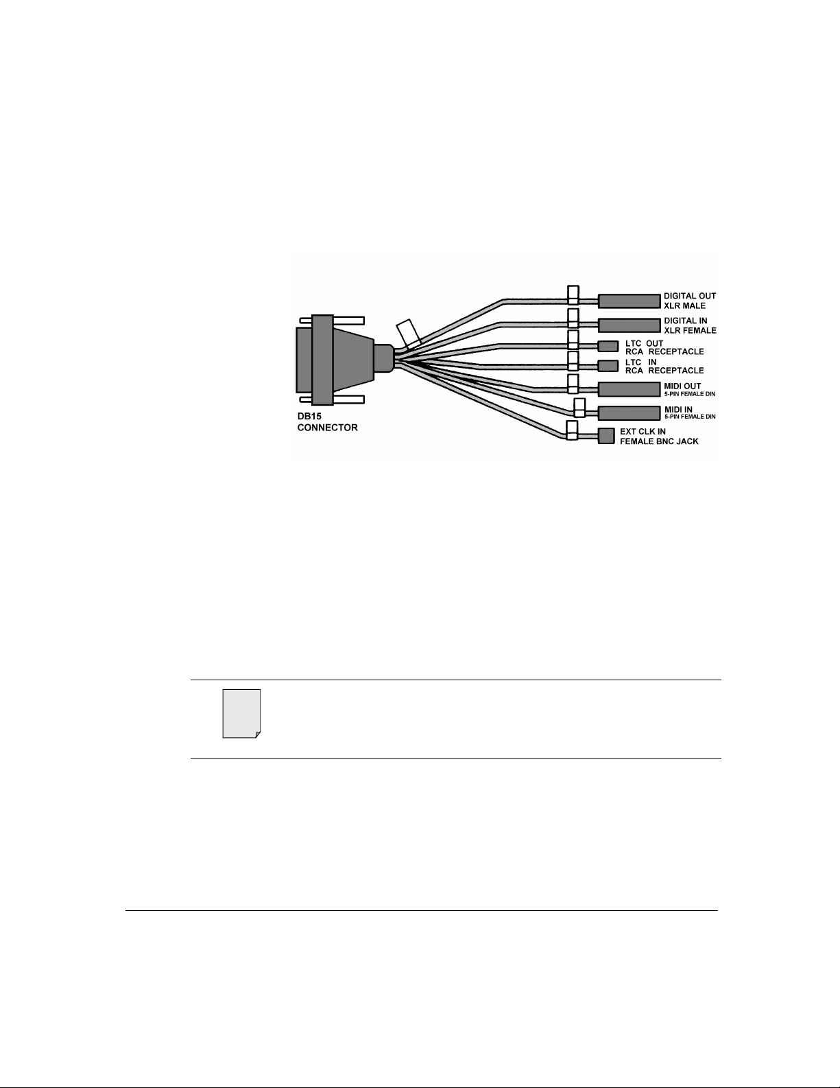
Appendix B I/O Port Pinouts and Cable Schematics........................B-1
Balanced Analog I/O Port Pinouts..............................................B-3
Four-Channel Balanced Analog I/O Cable Schematic ...............B-4
Balanced-to-Singled-Ended Adapter Schematic ........................B-5
Digital I/O and Sync Port Pinouts ...............................................B-6
Digital I/O Cable Schematic........................................................B-7
vi Antex StudioCard Copyright © 1997
Page 7

Chapter 1
Chapter 1
Chapter 1
Chapter 1 Chapter 1
Installing Your
Installing Your
Installing Your Installing Your
StudioCard
StudioCard
StudioCardStudioCar d
Overview.....................................................................................1-3
Quick Start..................................................................................1-4
StudioCard Components ............................................................1-5
Minimum System Requirements ................................................1-6
Installing Your StudioCard..........................................................1-7
Connecting Your External Equipment ......................................1-15
Installing StudioCard NT Drivers and Software........................1-18
Installing Windows 95/98 Drivers.............................................1-24
Installing Antex Demo and Mixer in Windows 95/98................1-26
Changing Driver Settings in Windows 95/98............................ 1-32
Updating Windows 95/98 Driver...............................................1-36
Troubleshooting Windows 95/98..............................................1-40
Antex Electronics Corporation Antex StudioCard 1-1
Page 8

Chapter 1
This page intentionally left blank.
1-2 Antex StudioCard Copyright © 1997
Page 9

Overview Chapter 1
Overview
Thank you for purchasing an Ant ex StudioCard 2000
(hereafter ref er r ed to as StudioCard). The StudioCard is a 4channel, professional quality audio adapter desig ned to add
the excitement of audio to the non-linear video editor’s t ool
set. W it h it s built in hardware “clock lock” you will never again
have to worry about “lip sync.” The StudioCard takes care of it
for you.
The StudioCard has all the feat ures professionals look for,
among them:
Balanced XLR connectors
Windows NT/2000 drivers
95 dB dynamic range
AES/EBU digital I/O
Read, generate, and screenburn SMPTE
With four channels of 20-bit sound and real-time dig it al m ixing
capability, the StudioCard offers unmatched quality, flexibility
and expandability. And by installing up to four StudioCards,
you can record and play up to 16 channels of digital sound on a
single PC.
To start adding studio quality sound to your editing
environment, simply follow the installation instruct ions
beginning on page 1-4.
Antex Electronics Corporation Antex StudioCard 1-3
Page 10
Chapter 1 Quick Start
Quick Start
Installing your StudioCard is relatively straightforward and is
accomplished in the 6 key steps shown below.
Make Sure You Have All
1
2
Install the StudioCard in Your Computer
3
Connect Your External Equipment
4
StudioCard Components
Verify that Minimum Installation
Requirements are Met
and Connect Internal Cables
to the StudioCard
Install Antex Drivers and Software
5
Test Your StudioCard
6
1-4 Antex StudioCard Copyright © 1997
Page 11

StudioCard Components Chapter 1
StudioCard
Components
Before getting star ted, make sure you have each of the
components listed below.
StudioCard 2000 (PN 9000-2419-3001)
StudioCard 2000 User’s Manual (PN 9000-2419-7007)
Cables:
Four-Channel Balanced Analog I/O Cable
(PN 210-0382)
Digital Audio I/O cable
(PN 210-0393)
Composite Video Cable Assembly
(PN 210-0397)
Internal PVR Clock Connection Cable
(PN 210-0398)
3.5 inch floppy disket t es:
Windows NT/2000 Driver for Intel-based m achines ( PN
9000-2362-7001)
Windows NT/2000 Software for Intel- based m achines
(PN 9000-2362-7005)
Windows 95/98 Driver (PN 9000-2390-7002) available
at ou r website: www.antex.com
Antex Electronics Corporation Antex StudioCard 1-5
Page 12
Chapter 1 Minimum System Requirements
e
Minimum
System
Requirements
Not
The StudioCard is designed f or system s t hat m eet the
following requirements:
IBM compatible PC with PCI Interface Bus
486-DX2/66 processor or higher
16 MB RAM
20 millisecond access time hard disk
VGA display
Windows NT/2000 3.51 or greater (4.0 recom mended)
If you are running Windows NT 3.51, inst all the Microsoft
Service Pack 4 before installing your Antex StudioCard.
The Microsoft Service Pack 4 is available at the following
Microsoft web site: http://www.microsoft.com/windows.
1-6 Antex StudioCard Copyright © 1997
Page 13

Installing Your StudioCard Chapter 1
g
Installing
Your
StudioCard
!
Follow the step-by-step instructions below to install your
StudioCard in your computer.
CAUTION: Static electricity can damage your
StudioCard and your computer. Every time you move,
you are creating static electricity, even though you
can’t see it. Therefore, take the following
precautionary actions while installing your StudioCard:
1. Do not remove the StudioCard from its anti-static
bag until instructed to during the inst allation
process.
2. Move the StudioCard and its cables i n cl ose
proximity to your computer. Once you begin the
installation process, do not walk around with the
StudioCard so that you do not build up static
electricity.
3. Power OFF your computer, then touch the nonpainted backside to discharge static electri ci ty from
your body before touching the circuit board.
CAUTION: The XLR outputs of the StudioCard may be
!
Antex Electronics Corporation Antex StudioCard 1-7
damaged if connected to microphone inputs that
provide phantom power. The StudioCard outputs are
designed to be connected to equipment that accepts
h level sources, not low level microphone inputs!
hi
Page 14

Chapter 1 Installing Your StudioCard
Severe damage will occur to the StudioCard if
connected to phantom power.
Step 1
Step 2
Step 3
Power off your computer (if you have not already done so) and
unplug the power cord from the elect r ical out let.
Remove the housing from your computer t o expose the
motherboard.
Writ e t he ser ial num ber for your Antex StudioCard in the space
below.
Serial Number: ___________________________________
If you ever need technical support from Ant ex in the future, you
will need this number. The serial number is on the backs ide of
your Antex StudioCard. Serial numbers are preceded by “S/N”
and contain five digits.
Example serial number: “S/N 48008”
1-8 Antex StudioCard Copyright © 1997
Page 15
Installing Your StudioCard Chapter 1
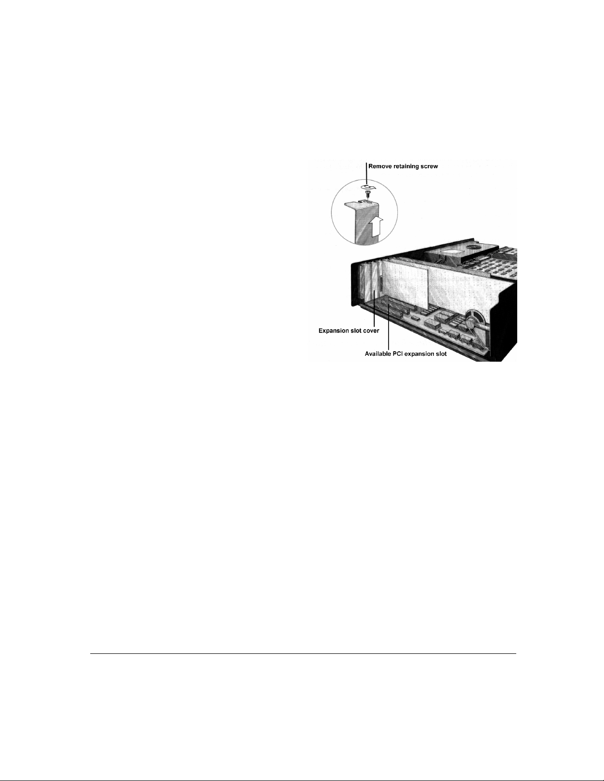
Step 4
Locate an available
PCI expansion slot
and remove its
cover, as is shown
in the figure at
right.
Be sure to keep the
retaining screw as
you will need it
later.
Antex Electronics Corporation Antex StudioCard 1-9
Page 16
Chapter 1 Installing Your StudioCard
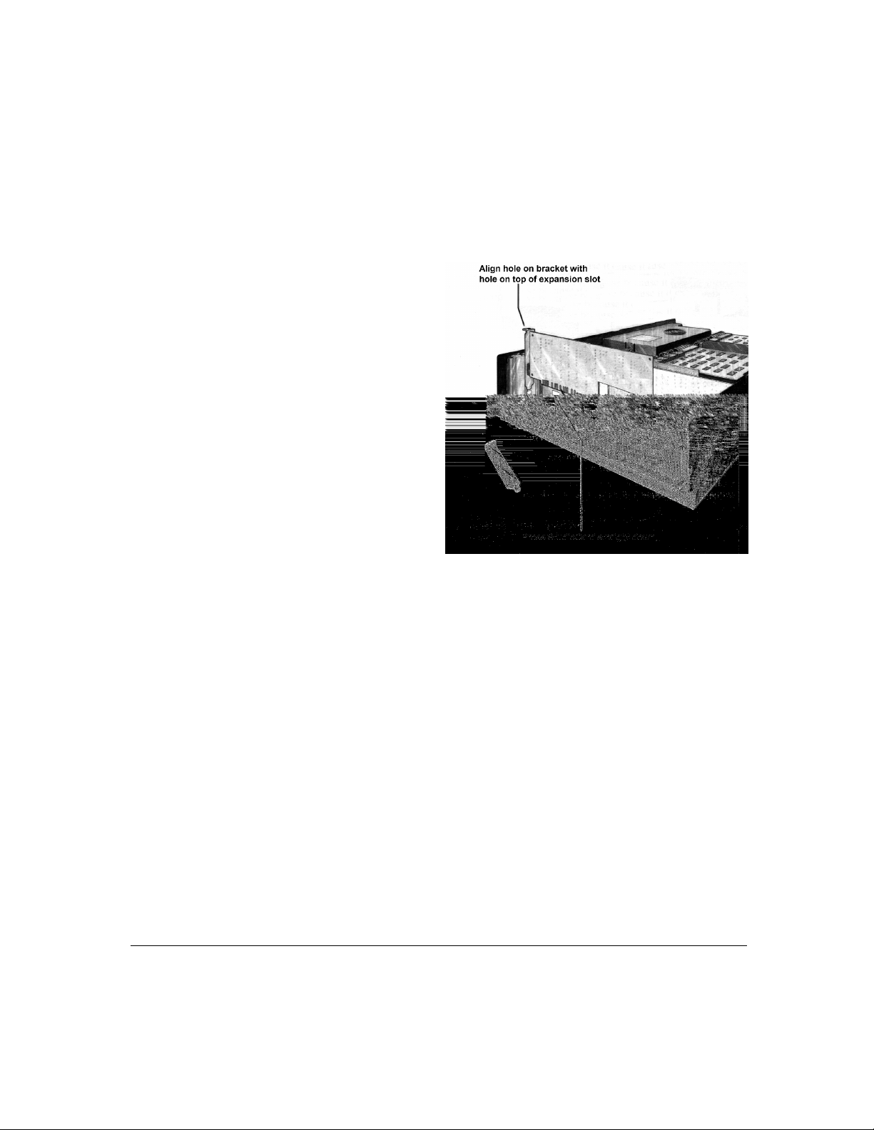
Step 5
Step 6
Step 7
Gently insert the
Antex StudioCard
into an available
PCI expansion slot,
then press down to
set it firmly into the
expansion slot, as
is shown in the
figure at right.
Secure the Antex StudioCard in place with the retaining screw
you removed earlier from the expansion slot cover.
If you are installing only one Antex StudioCard at this time,
continue to Step 8.
If you are installing two or more Antex StudioCard cards, skip
to Chapter 5, Synchronizing Multiple StudioCard Cards now.
Then, return to Step 9 when finished.
Step 8
1-10 Antex StudioCard Copyright © 1997
If you will be using your StudioCard in conjunction with the
Perception PVR without t he Percept ion Effects board (PFx),
continue to Step 9.
If you are using the PFx board with the PVR or a video capture
board from any other manuf act ur er (Truevision, Intergraph,
Matrox or other), skip to step 11.
Page 17

Installing Your StudioCard Chapter 1
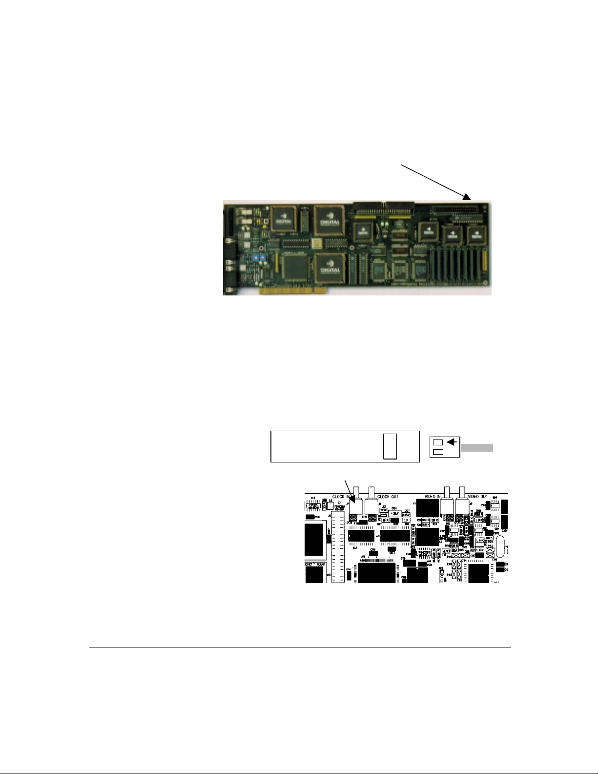
Step 9
The DPS PVR provides a 27MHz clock on the CVE-2 video
bus expansion connector. This signal will be connected to the
StudioCard using the provided Sync cable, PN 210-0398, as
the master clock refer ence. The StudioCard and the PVR
must be located near enough for t he cable to reach between
the boards.
Locate the PVR Sync cable. On the black plastic end, identify
the pin with the embossed arrow.
Orientation of this pin during
installation is extremely important.
Antex Electronics Corporation Antex StudioCard 1-11
Page 18
Chapter 1 Installing Your StudioCard
You will connect to the PVR board here.
With the com put er turned OFF, insert the end of the cable with
the flat black plastic connector over pins 37 and 38 on the
CVE-2 video bus expansion connector on the PVR board. The
embossed arrow on the plastic connector must be
oriented toward the top edge of t he PVR board. The
locations of pins 37 and 38 are shown below.
2 4 6 8 …………………. 38 40
1 3 5 7 …………………. 37 39
Step 10
Connect the metal
SMB connector on
the other end of
the cable to the
gold CLOCK IN
connector on the
top of the
StudioCard.
1-12 Antex StudioCard Copyright © 1997
Page 19
Installing Your StudioCard Chapter 1
e
When using the PVR Sync cable as installed above in
Not
Steps 9 and 10, the clock source must be set to Int er nal,
Reference 27MHz, in the Antex Mixer. When using
Composite Video as the clock synchronization source as
described below in Steps 11-15, the clock source must be
set to Hsync in the Antex Mixer. The Antex Mixer is
described in Chapter 3.
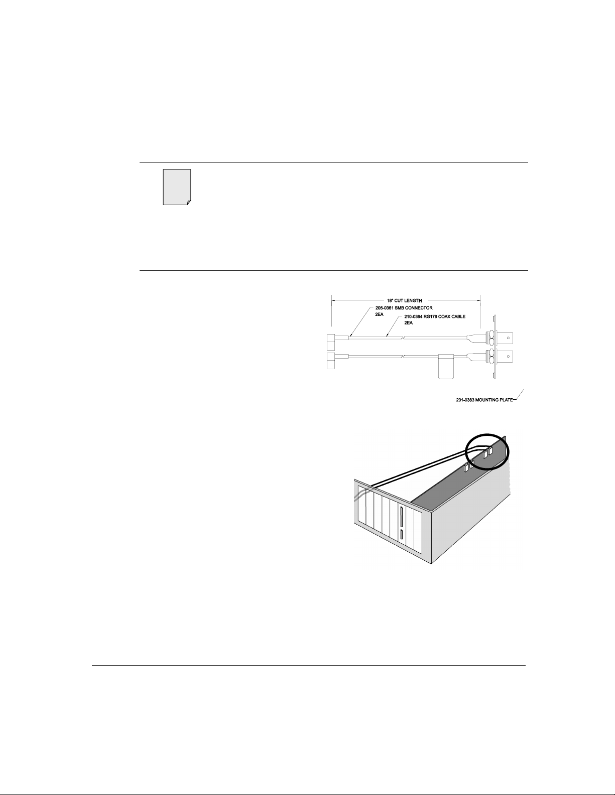
Step 11
Step 12
Locate the Video
Cable Assembly
shown at right. This
cable loops composite
video through the
StudioCard for use as
a clock reference as
well as the signal into
which SMPTE can be
screenburned.
Plug the SMB
connectors of the
Video Cable
Assembly into the
gold Video Input and
Video Output
connectors on the
StudioCard, as shown
at right. The input
and output are clearly
marked on the board.
Antex Electronics Corporation Antex StudioCard 1-13
Page 20
Chapter 1 Installing Your StudioCard
Step 13
Step 14
Locate an available 25-pin D connector punch-out on the back
panel of the computer and remove the punch-out . (The cable
bracket has been designed not to require a typical computer
bracket which would waste a card slot. It fits in a 25 pin D
connector punch out available near the power supply of most
computer cases.)
If there is no 25 pin punch-out available, you must procur e a
bracket with a hole for a 25 pin D connector. The bracket
requires the same size cutout as a parallel port connector and
is available at most computer stores.
From the inside of the computer , insert the Video Cable
Assembly mounting plate into the punch-out, then secure it in
place with the two screws provided. Label which BNC you
have connected to Video In and Video Out on the card.
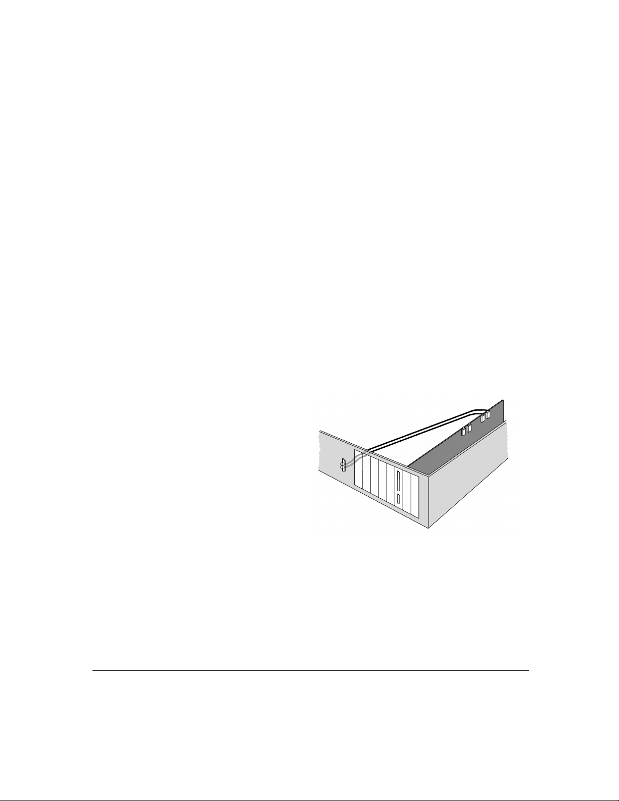
A properly
installed Video
Cable Assembly
should look
like that
shown at
right.
Step 15
1-14 Antex StudioCard Copyright © 1997
Replace the cover on your computer and secure it in place with
the screws you removed earlier.
The next step in the StudioCard installation process is to
connect your external A/V equipment to the StudioCard. Refer
to the instructions beginning on page 15.
Page 21
Connecting Your External Equipment Chapter 1
Connecting
Your External
Equipment
Step 1
Follow the instructions below to connect your external audio
and video equipment to the StudioCard. Also refer to the user
manuals of your video capture device and other external
equipment.
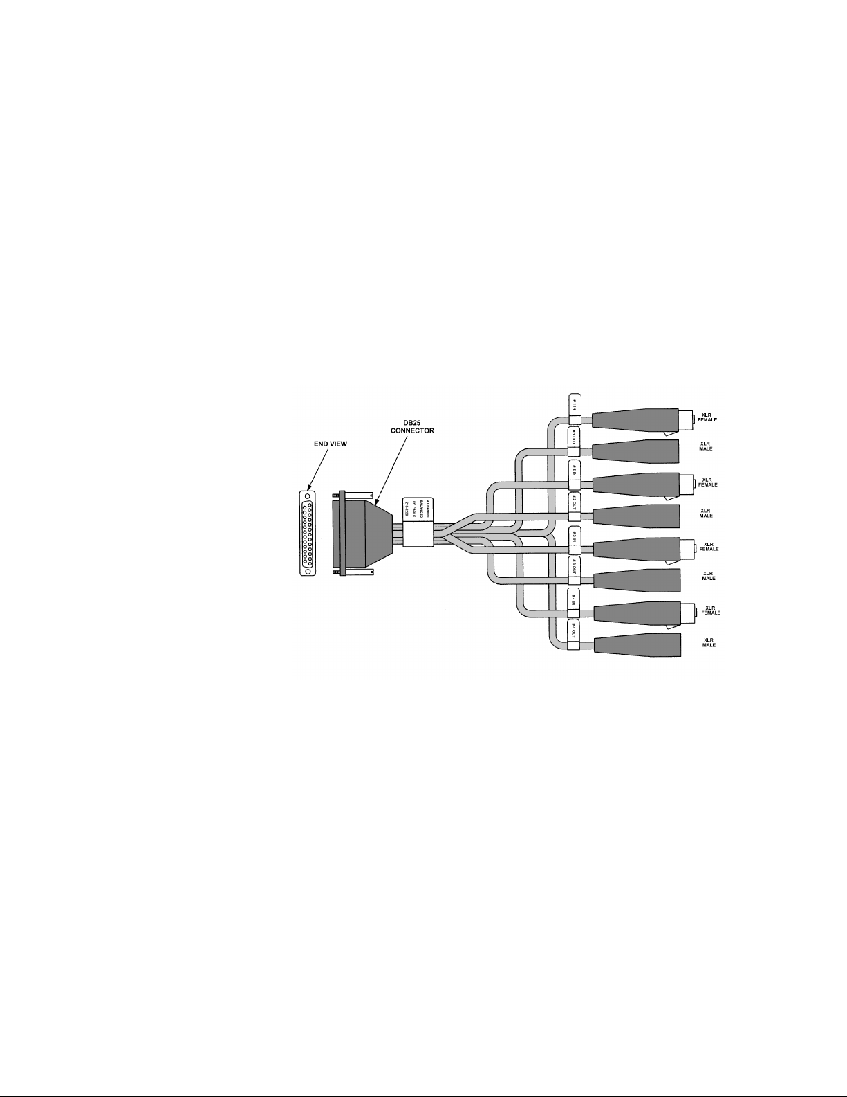
Locate the Four-Channel Balanced Analog I/O Cable shown
below.
Step 2
Antex Electronics Corporation Antex StudioCard 1-15
Attach the Four-Channel Balanced Analog I/O Cable to the
analog Balanced I/O port on the bracket and secure it in place
with the locking screws.
Notice that there is a white tag on each connector that indicates
which are input connectors and which are output.
Page 22
Chapter 1 Connecting Your External Equipment
e
Step 3
Step 4
Step 5
Locate the Digital Audio I/O Cable show below.
Attach the Digital Audio I/O Cable to the Digital Audio and Sync
I/O port on the bracket and secure it in place with the locking
screws.
Attach your external audio / video equipment to the appropr iat e
analog and digital cable connectors, using t he white tags above
each connector for reference.
Specific pinout information is provided in Appendix B.
Not
Step 6
1-16 Antex StudioCard Copyright © 1997
Theory of Operation information for these cables is
provided in Chapter 6.
Plug in your computer and power it on.
Page 23

Connecting Your External Equipment Chapter 1
The next step in the installation process is to install the Antex
StudioCard drivers and software. Refer to the instructions
beginning on page 18, Installing St udioCar d Drivers and
Software.
CAUTION: The XLR outputs of the StudioCard may be
!
damaged if connected to microphone inputs that
provide phantom power. The StudioCard outputs are
designed to be connected to equipment that accepts
high level sources, not low level microphone inputs!
Severe damage will occur to the StudioCard if
connected to phantom power.
Antex Electronics Corporation Antex StudioCard 1-17
Page 24
Chapter 1 Installing StudioCard NT Drivers and Software
e
Installing
StudioCard
NT Drivers
and Software
Not
Step 1
The StudioCard comes with two programs—Antex Demo and
Antex Mixer—as well as drivers for Windows NT/2000.
The Antex Demo is used primarily for t esting your
StudioCard and demonstrating it s capabilit ies.
The Antex Mixer is a powerful patch bay, mixing console,
and configuration tool for the StudioCard.
To install the drivers, Antex Demo, and Ant ex Mixer, simply
follow the step-by-step instructions below.
Be sure to check Antex’ web site periodically for the latest
StudioCard drivers. Our web address is www.antex.com.
Insert the appropriate Antex Drivers and Software diskette into
your floppy drive.
If your computer has an
Intel processor, use the
PN 9000-2362-7001 disk.
If your computer has an
Alpha processor, use the
PN 9000-2362-7004 disk.
1-18 Antex StudioCard Copyright © 1997
Page 25
Installing StudioCard NT Drivers and Software Chapter 1
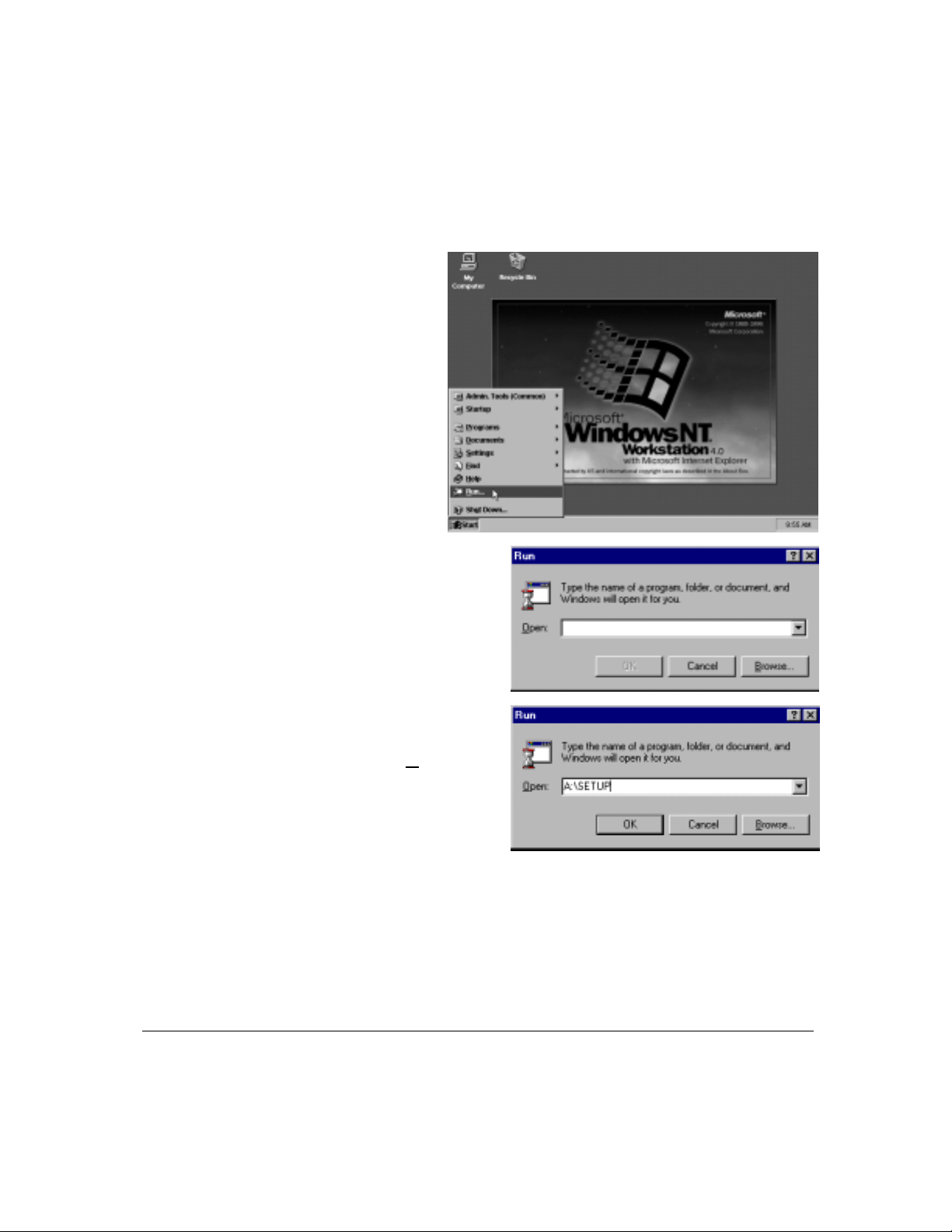
Step 2
Click Start
on your
Windows
NT/2000
desktop,
then select
Run, as is
shown at
right.
The Run dialog
box shown
at right appears.
Step 3
Antex Electronics Corporation Antex StudioCard 1-19
Type A:\SETUP
(or B:\SETUP),
then click O
K.
Page 26
Chapter 1 Installing StudioCard NT Drivers and Software
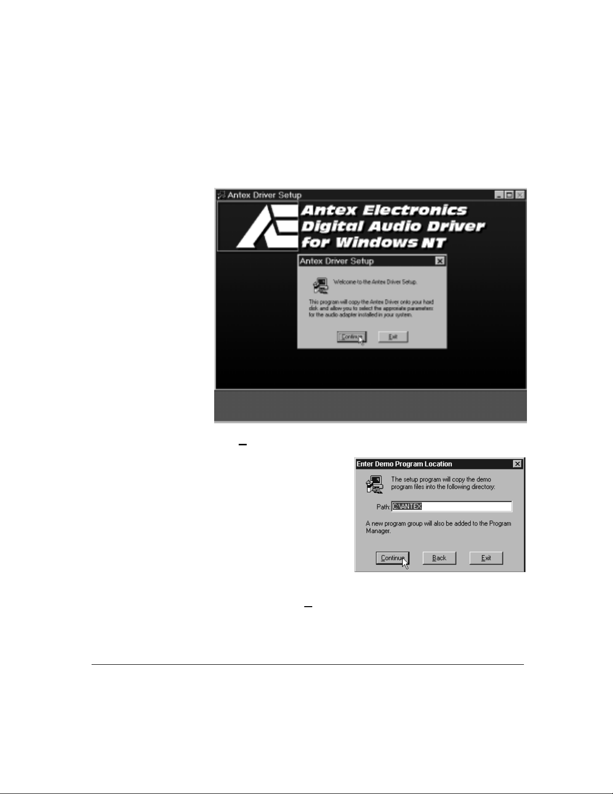
Step 4
The Antex Driver Setup pop-up appears
Click Continue to proceed with setup
Step 5
1-20 Antex StudioCard Copyright © 1997
The Enter Demo
Program Location
dialogue box appears.
Enter a location for the Antex Demo programs (or accept t he
default), then click C
ontinue.
Page 27
Installing StudioCard NT Drivers and Software Chapter 1
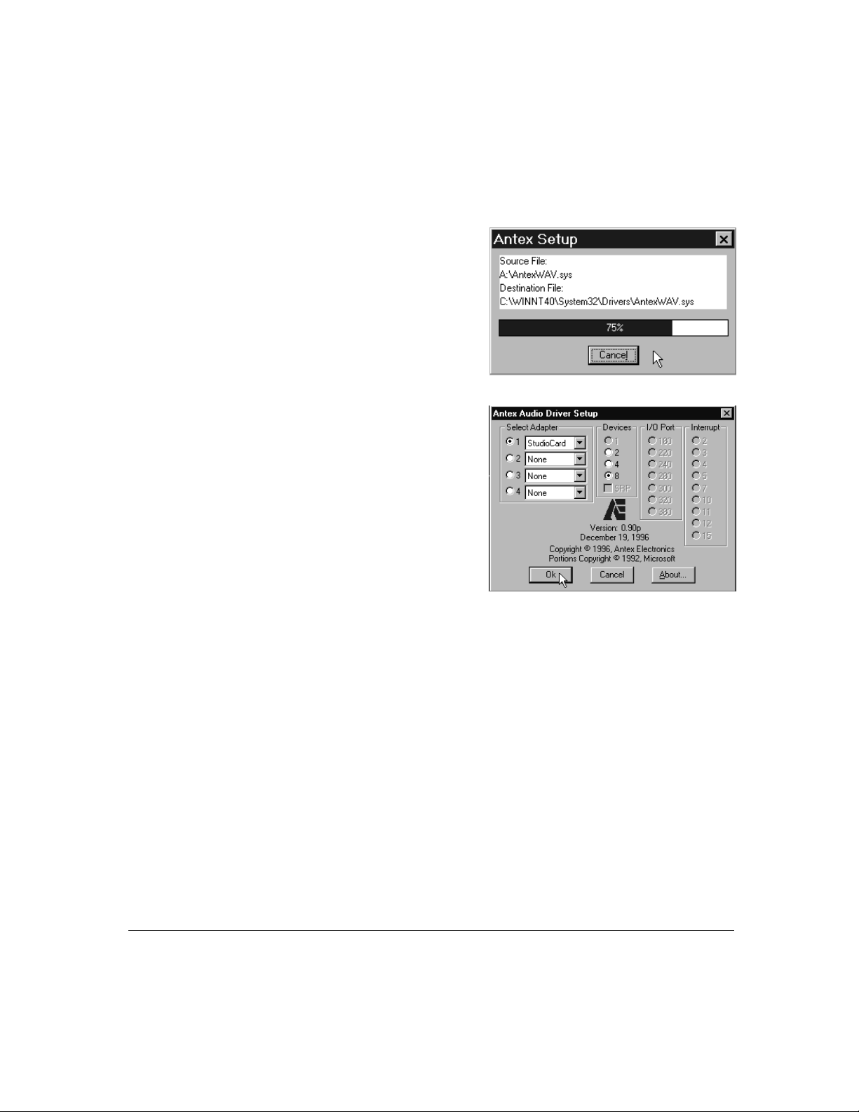
The Antex Setup
pop-up appears and
reports the progress
of the installation.
When the inst allat ion is
complete, you will see the
Antex Audio Driver Setup
window shown at right.
Notice that default
selections are displayed in
both the Select Adapter
and Devices groups.
The Select Adapter setting allows you to configure one or more
StudioCard cards. The Devices setting indicates to Windows
NT/2000 how many stereo or mono files each StudioCard is
configured to allow.
Step 6
Antex Electronics Corporation Antex StudioCard 1-21
If you are installing only one Antex StudioCard card, accept the
default settings (Select Adapter = 1 and Devices = 8). The
options in the Devices block are explained in Chapter 3.
If you are installing more than one StudioCard card, set
Devices to 8 for each card (Adapter). Simply click an adapter
(for example 2), then select 8 in t he Devices group, until you
have set the devices for all adapters.
Page 28
Chapter 1 Installing StudioCard NT Drivers and Software
Step 7
Step 8
Click OK to complete the drivers and sof t ware installat ion. The
Setup program will automatically configure the I/O port and
interrupt.
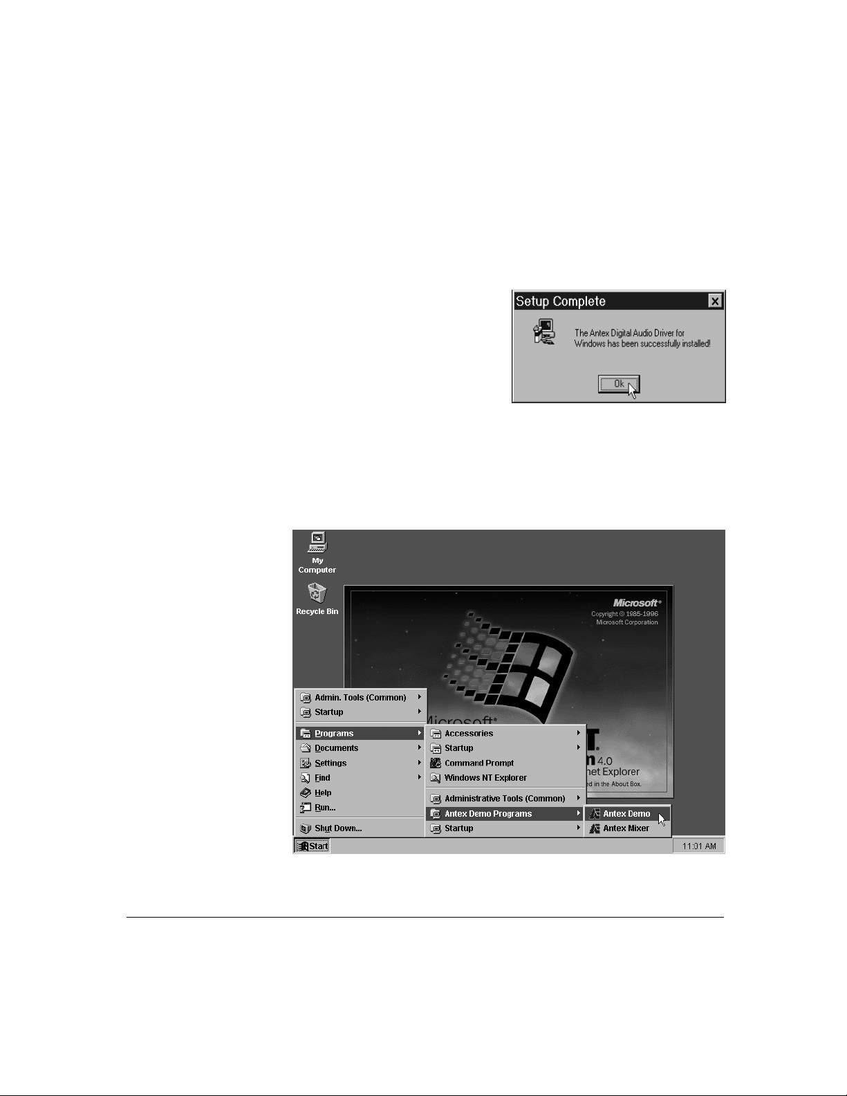
When the drivers and software
installation is complete, the
Setup Complete pop-up
appears.
Click OK to exit the Antex Driver Setup progr a m and r eturn to
the Windows NT/2000 desktop.
During the installation process, a new program group, Antex
Demo Programs, was created in your program list, as is shown
below.
1-22 Antex StudioCard Copyright © 1997
Page 29

Installing StudioCard NT Drivers and Software Chapter 1
The final step in installing your StudioCard is to test its
playback and recording capabilities. Consult the sect ion
entitled Playing *.WAV Files in Chapter 2, Using t he Antex
Demo.
Before playing a wave file for the first time, turn down
!
the volume on your audio equipment. The StudioCard
default output level is quite l oud.
Antex Electronics Corporation Antex StudioCard 1-23
Page 30
Chapter 1 Installing Windows 95/98 Drivers
e
Installing
Windows
95/98 Drivers
Not
Step 1
Step 2
To install the Windows 95/98 drivers, simply follow the stepby-step instructions below.
Please note that the Antex Demo and Antex Mixer are
installed separately from the drivers in Windows 95/98.
Installation instructions for these programs follow this section.
Be sure to check Antex’ web site periodically for the latest
StudioCard drivers. Our web address is www.antex.com.
It is recommended the files are unzipped, copied to a
floppy, and installed from the floppy disk.
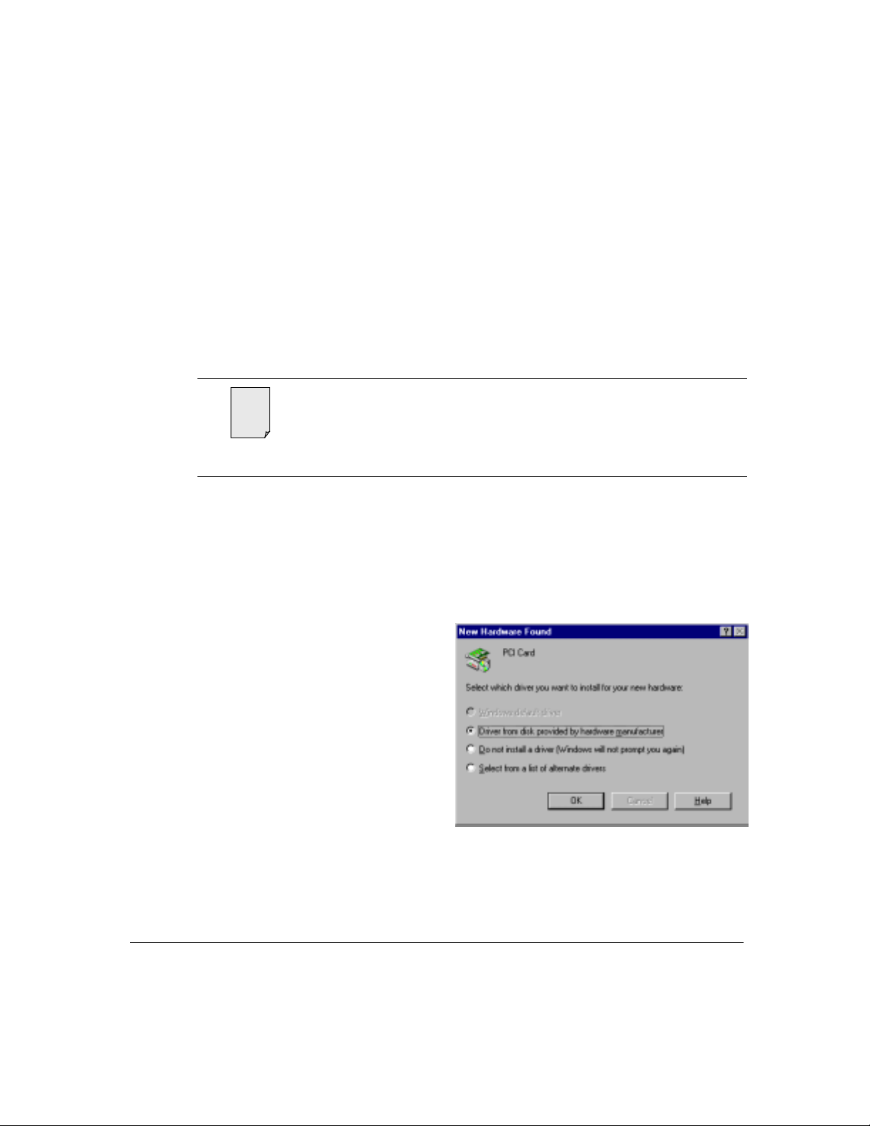
After installing the StudioCard, power on the computer.
Windows 95/98 Plug and Play will recognize the new hardware
and ask you to install drivers for it.
Insert the Windows 95/98 Driver and Software diskette into the
floppy drive, PN 9000-2390-7002.
The following dialog
box will appear.
Verify “Driver from
disk provided from
hardware
manufacturer” is
checked, and click
OK.
1-24 Antex StudioCard Copyright © 1997
Page 31

Installing Windows 95/98 Drivers Chapter 1
Step 3
Step 4
Verify the W indows
95/98 driver diskette
is inserted into driver
A: and click OK.
Select the
StudioCard and
click OK.
Installation of the drivers will proceed and complete aut om atically
from this point. You may be ask ed t o r eboot when installation is
completed. If so, select Yes and reboot.
You may also need to configure your soft ware application.
Users of Cakewalk Pro Audio are recom m ended t o set the
StudioCard W ave Out 1 and Wave In 1 as the timing masters
under Settings/Audio Options. Under advanced, select
Simultaneous Record and Play. The Wave Profiler should also
be run.
Antex Electronics Corporation Antex StudioCard 1-25
Page 32

Chapter 1 Installing Antex Demo and Mixer in Windows 95/98
Installing
Antex Demo
and Mixer in
Windows
95/98
Step 1
To install the Antex Demo and Antex Mixer in Windows
95/98, simply follow the step-by-step instructions below.
The Antex Demo is used primarily for testing your StudioCard
and demonstrating its capabilities.
The Antex Mixer is a powerful patch bay, mixing console, and
configuration tool for the StudioCard.
To install,
select
Start/Settings/
Control Panel
as shown at
right.
1-26 Antex StudioCard Copyright © 1997
Page 33

Installing Antex Demo and Mixer in Windows 95/98 Chapter 1
Step 2
Step 3
The following screen
will appear. Double
click on Add/Remove
Programs.
The Add/Remove
Program Properties
dialog box appears.
Click Install.
Antex Electronics Corporation Antex StudioCard 1-27
Page 34

Chapter 1 Installing Antex Demo and Mixer in Windows 95/98
Step 4
Step 5
Verify the floppy disk
is still in the drive,
and click Next.
Verify the path is
A:\SETUP.EXE and
click finish.
1-28 Antex StudioCard Copyright © 1997
Page 35

Installing Antex Demo and Mixer in Windows 95/98 Chapter 1
Step 6
Step 7
The location for the
program files may be
selected. Click Next
or select a new
location by selecting
Browse.
Select Next, and
installation will
proceed
automatically.
Antex Electronics Corporation Antex StudioCard 1-29
Page 36

Chapter 1 Installing Antex Demo and Mixer in Windows 95/98
Step 8
Click Finish and
installation of the
Antex Demo and
Antex Mixer are
completed.
1-30 Antex StudioCard Copyright © 1997
Page 37

Installing Antex Demo and Mixer in Windows 95/98 Chapter 1
The Antex demo and Mixer will be installed under Programs/StudioCard
Applications as shown below.
Antex Electronics Corporation Antex StudioCard 1-31
Page 38

Chapter 1 Changing Driver Settings in Windows 95/98
Changing
Settings in
Windows
Driver
95/98
Step 1
There is only one setting that may be changed for the driver.
This is the number of wav devices and whether the driver is in
SRP or Simultaneous Record Play mode. The description of
SRP is in Chapter 3. Certain applications such as Cakewalk
Pro Audio work best in SRP mode, either 2 or 4 devices.
Setting the driver to 8 devices, non-SRP requires a large
display area within certain applications.
Select Start\
Settings\Control
Panel.
1-32 Antex StudioCard Copyright © 1997
Page 39

Changing Driver Settings in Windows 95/98 Chapter 1
Step 2
Step 3
Double click on
System.
Highlight the
Device Manager
tab and expand
Sound, video and
game controllers
by clicking on the
plus sign. Double
click on StudioCard
to bring up its
properties.
Antex Electronics Corporation Antex StudioCard 1-33
Page 40

Chapter 1 Changing Driver Settings in Windows 95/98
Step 4
When the
properties dialog
box appears,
highlight the
configuration tab.
The default
installation is
shown.
1-34 Antex StudioCard Copyright © 1997
Page 41

Changing Driver Settings in Windows 95/98 Chapter 1
e
Step 5
Select the 2 or 4
checkbox, and the
SRP checkbox
becomes active.
Check the box to
the left of SRP and
click OK. The
driver will then be
set for two or four
devices that can
each record and
play.
Selecting the Resources tab on the StudioCard Properties
Not
may cause your system to appear frozen. There is typically
no reason to view Plug and Play Resources. If this does
happen, be patient, as the system will come back after
several minutes. This delay is due to a limitation in
Windows 95/98. You may also Ctrl-Alt - Del t o end t he
Windows task.
Antex Electronics Corporation Antex StudioCard 1-35
Page 42

Chapter 1 Updating Windows 95/98 Driver
Updating
Windows
95/98 Driver
Step 1
New drivers will be released from time to time and made
availa ble on www.antex.com. I t is suggest ed you copy the
new driver to a floppy disk, and update the driver using the
following procedure.
Open Control
Panel and
double click on
the System
Icon.
1-36 Antex StudioCard Copyright © 1997
Page 43

Updating Windows 95/98 Driver Chapter 1
Step 2
Step 3
Click on Device
Manager tab,
expand Sound,
video and game
controllers by
clicking on the
plus sign next to
it. Double click
on the
StudioCard to
bring up its
Properties.
Click on Driver
tab, and click on
Change Driver.
Antex Electronics Corporation Antex StudioCard 1-37
Page 44

Chapter 1 Updating Windows 95/98 Driver
Step 4
Step 5
Step 6
Select the
StudioCard and
click on Have
Disk.
Verify the path
is to the A:\
floppy, and click
OK.
Windows will
check which
drivers are on
the floppy.
Verify the
StudioCard
appears and
click OK.
1-38 Antex StudioCard Copyright © 1997
Page 45

Updating Windows 95/98 Driver Chapter 1
Step 7
Step 8
The Driver
Properties
screen will
reappear. Click
OK.
Verify floppy is
still in drive and
click OK.
Step 9
Antex Electronics Corporation Antex StudioCard 1-39
Verify the path
is A:\ (NOT
A:\Antex.inf)
and click OK.
The driver will
be updated. You
must reboot for
the change to
take effect.
Page 46

Chapter 1 Trouble-shooting Windows 95/98
Trouble-
shooting
Windows
95/98
Step 1
Step 2
All PCI cards such as the StudioCard are Plug and Play
compliant. Older “legacy” ISA cards may or m ay not be. The
most likely problem you may encounter during installat ion is a
resource conflict. This is t ypically due to Windows 95/98 Plug
and Play system not being aware of older ISA based cards in
your system. Windows believes a particular IRQ is available
and assigns it to the StudioCard when it is really in use by
another device.
These conflicts occur most frequently with ISA based modem,
network, and other sound cards. This sect ion will assist you in
resolving a conflict if you do have one.
Power down and remove the StudioCard
Determine the
resources used
by legacy cards
in the system.
This is
accomplished
by double
clicking on the
System Icon in
the Control
Panel.
1-40 Antex StudioCard Copyright © 1997
Page 47

Trouble-shooting Windows 95/98 Chapter 1
Step 3
Step 4
Highlight the
Device Manager
Tab. Expand
suspect devices
by clicking on
the plus sign.
Then, double
click on the
device to bring
up its
Properties.
Click on the
Resource tab to
determine which
IRQ the device
uses. Wr it e t h is
down and
repeat this
process for
each suspect
ISA card in the
system.
Antex Electronics Corporation Antex StudioCard 1-41
Page 48

Chapter 1 Trouble-shooting Windows 95/98
Step 5
Step 6
Enter Bios at startup by pressing the Del key. In most Plug and
Play Bios, there is a method to assign IRQ’s to legacy devices so
that W indows 95/98 cannot use them . In this way, the possibility of
Windows assigning an IRQ t o t he StudioCard, which causes the
conflict, can be eliminated. Each Bios is different, consult your user
manual or manufacturer of your computer system to determine how
to accomplish this.
Step 4 Power down, install the StudioCard, and proceed with driver
installation.
1-42 Antex StudioCard Copyright © 1997
Page 49

Trouble-shooting Windows 95/98 Chapter 1
This page intentionally left blank.
Antex Electronics Corporation Antex StudioCard 1-43
Page 50

Chapter 3
Chapter 3
Chapter 3
Chapter 3 Chapter 3
Using the Antex Mixer
Using the Antex Mixer
Using the Antex MixerUsing the Antex Mixer
Introduction to Antex Mixer.........................................................3-3
Why Would I Use the Antex Mixer? .....................................3-3
Starting the Antex Mixer .............................................................3-4
Mixer Controls and Indicators.....................................................3-5
Main Screen Controls and Indicators...................................3-5
Adapter Line Controls and Indicators...................................3-7
Timecode Options..............................................................3-10
Adjusting the Antex Mixer Display............................................3-12
Selecting the Active Antex Mixer..............................................3-15
Saving Antex Mixer Settings..............................................3-16
Recalling Saved Mixer Settings .........................................3-18
Non-mixdown Mode...........................................................3-21
Two-Device / Four-Device Operation.......................................3-23
Simultaneous Record-Play (SRP) Mode ..................................3-26
Antex Electronics Corporation Antex StudioCard 3-1
Page 51

Chapter 3
This page intentionally left blank.
3-2 Antex StudioCard Copyright © 1997
Page 52

Introduction to Antex Mixer Chapter 3
Introduction
to Antex Mixer
Why Would I Use the
Antex Mixer?
The Antex Mixer is a software tool designed to be used in
conjunction with application software such as In-Sync’s
Speedrazor and Innovative Quality Software’s SAW Plus. It is
a powerful program that allows you to configure many features
of the StudioCard. Using the Mixer you can:
Set sample clock r eference source
Set sample rate for input sources
Control all timecode and scr eenbur n functions
Control and routing of physical inputs and outputs to logical
devices used by Windows NT/2000
Set the digital I/O format; either AES/EBU Professional or
S/PDIF Consumer
Set input and output t rim levels
Set relative volumes for true mixer operation
The Antex Mixer is used in conjunction with other software
applications, either the Antex Demo or a Non-Linear Video
editing program to configure the StudioCard for audio
recording.
The settings you specify in the Antex Mixer define how the
StudioCard operates. It is a useful tool which allows you to
change settings and control volume. If you find that you need
to change Mixer settings frequent ly, it is a good idea to keep it
open in the background or minimized.
Antex Electronics Corporation Antex StudioCard 3-3
Page 53

Chapter 3 Starting the Antex Mixer
Starting the
To open the Antex Mixer program, select Start - Programs Antex Demo Programs - Antex Mixer, as illustrated below.
Antex Mixer
The Antex Mixer
program opens.
Shown at right is
the default display
showing Line In,
Digital In, Line
Out, and four
each record and
play controls.
This default configuration allows the Antex Mixer to fit into a
640 x 480 pixel (standard VGA) display. The display can be
modified to display up to four additional r ecor d and play
controls, and adapter settings. See Adjusting the Antex Mixer
Display on page 12.
3-4 Antex StudioCard Copyright © 1997
Page 54

Mixer Controls and Indicators Chapter 3
Mixer
Controls and
Indicators
Main Screen
Controls and
Indicators
In this section are descriptions of all the controls and indicators
of the Antex Mixer display, including its sub-menus.
A simplified display of the Antex Mixer is shown below. The
default configur at ion act ually displays f our record and play
controls, only one is shown for clarity as they are identical.
Each of these controls and indicators is described in t he table
on the next page.
Antex Electronics Corporation Antex StudioCard 3-5
Page 55

Chapter 3 Mixer Controls and Indicators
Main Screen
Control
Line In Trim Trim slider control used to adjust the clipping level of the analog input signal to either
1
Rec 1 level
2
controls
Rec 1
3
1, 2, 3, 4
Line In
4
On/Off
Digital In
5
On/Off
Play 1 AVol Avol (Automatic Volume adjustment) selector button, highlighted in green when
6
Play 1
7
1, 2, 3, 4
Play Output
8
Level Control
Line Out
9
Trim
Line Out
10
Output Level
Indicators
Rec 1 Level
11
Indicators
Description
+12 dBu or +24 dBu. Output trim is moved in unison. See Chapter 4 for more
information regarding levels.
Level controls used to adjust the volume of the left and right stereo signal at the Rec
1 channel. If Rec 1 is defined by the application software to be mono rather than
stereo, only the left slider and 1-4 buttons (Item 3) are valid. The relative signal level
is indicated by the level indicators (item 11).
1, 2, 3 & 4 selector buttons, highlighted when selected. These buttons represent the
physical inputs 1-4 as marked on the analog I/O cable. Only one can be selected at a
time. Used to select which of the four analog signal inputs (1 - 4) will correspond to the
left and right inputs to this device (only left column is valid for a mono device).
On/Off selector button, highlighted and reads On when selected, Off when
deselected. Mutually exclusive with Digital In selector button. When selected, the
input signal to the Mixer is an analog signal supplied via the DB25 analog
input/output connector on the back of the StudioCard.
On/Off selector button, highlighted and reads On when selected, Off when
deselected. Mutually exclusive with “Line In” selector button. When selected, the
StudioCard is set for digital input and expects digital data via the digital I/O cable.
When digital in is enabled, it replaces analog inputs 1 and 2. Application software
recording from device 1 with digital in enabled expects data input digitally.
selected. Used only during playback of Mono files. When selected, the StudioCard
duplicates data and volume settings of the left half of the playback device to a
second physical output. Output 1 is copied to Output 2, Output 3 is copied to Output
4 in the default configuration. Stereo files are played back normally.
1, 2, 3 & 4 selector buttons, highlighted when selected. These buttons represent the
physical outputs 1-4 as marked on the analog I/O cable. Multiple buttons may be
selected, routing a file from disk to multiple physical outputs.
Stereo pairs of level controls for the four analog output channels. When a file is
mono, only the left slider is valid.
Trim slider control used to adjust the clipping level of the analog output signal to
either +12 dBu or + 24 dBu. Input trim setting is moved in unison. See Chapter 4 for
more information regarding levels.
Indicators, one for each of the four analog signal outputs. Indicate the relative signal
level at each output, leftmost meter is output one, rightmost output four.
Level indicators that indicate the relative level of the left and right stereo signal at the
Rec 1 channel. The signal level is affected by the setting of level controls (item 2).
3-6 Antex StudioCard Copyright © 1997
Page 56

Mixer Controls and Indicators Chapter 3
Adapter Line
Controls and
Indicators
The Adapter controls shown below can be added to the Antex
Mixer main screen simply by choosing Lines from the Mixer
menu, then selecting Adapter.
Each of the Adapter controls and indicator s indicat ed below is
described in the table on the next page. Beginning on page
3-10 is a description of each of the cont r ols and indicators
displayed when you click the Timecode Options button (#15).
Antex Electronics Corporation Antex StudioCard 3-7
Page 57

Chapter 3 Mixer Controls and Indicators
Adapter Controls Description
Sample Clock
1
Source DSPClock
Sample Clock
2
Source Internal
Sample Clock
3
Source External
Sample Clock
4
Source HSync
Sample Clock
5
Source Digital
Sample Clock
6
Reference Auto
Sample Clock
7
Reference
27MHz
The physical source of the audio sample clock is derived from this selection.
When DSP is selected, the sample clock generator signal source is the internal
clock on the Digital Signal Processor card (StudioCard). See note at end of
table..
Internal selector. When selected, the sample clock generator signal source is
supplied through the CLOCK IN connector on the top of the StudioCard internal
to the computer. This is the correct setting for the PVR without the PFx board or
for slave StudioCards in multiple card installations. See note.
External selector. When selected, the sample clock generator signal source is
supplied from the External Clock In female BNC connector of the Digital I/O
cable. See note.
HSync selector. When selected, the sample clock generator signal source is
supplied from a composite video or composite sync signal source through the
VIDEO IN connector on the top of the StudioCard. This is the correct setting for
many video capture boards. NOTE: The signal source must be a stable one,
such as from a time base corrector or sync generator. The uncorrected output
from a VTR is not adequate. See note.
Digital selector. When selected, the sample clock generator signal source is the
word clock derived from the digital input (AES/EBU or S/PDIF). See note.
Auto selector. When selected, the sample clock generator will automatically
determine the frequency of the selected clock source. This is the only valid
option for the DSP-Clk and Digital In. The DSP-clock is a fixed 20 MHz clock.
The Digital In is always a word clock. See note.
27MHz selector. When selected, the sample clock generator will assume that
the selected clock source has a frequency of 27 MHz. This is the correct setting
for the PVR when connected via the PVR sync cable, PN 210-0398 (PFx not
installed). Supports 13.5MHz and 54MHz clocks also. See note.
Sample Clock
8
Reference Word
3-8 Antex StudioCard Copyright © 1997
Word selector. When selected, the sample clock generator will treat the selected
clock source as a word clock with a frequency identical to the desired sampling
rate. The sampling point of the StudioCard’s A/D and D/A occurs on the rising
edge of the input word clock. This provides a means to maintain coherency with
other digital audio devices. Valid word clock frequencies are 32, 44.1 and 48
kHz. Slave devices in multiple card installation use an internal word reference.
See note.
Page 58

Mixer Controls and Indicators Chapter 3
Sample Clock
9
Reference
Word256
Sample Rate Sample rate selector. Selects the sample rate of the incoming sample clock
10
Digital Format
11
AESEBU/
Consumer
Time Code Burn
12
In Select
Time Code
13
Generate
Time code Out
14
Position
Time code
15
Options
Time Code MTC
16
Record
Time code In
17
Position
Word256 selector. When selected, the sample clock generator will assume that
the selected clock source has a frequency 256 times the desired sample rate.
See note.
signal. This parameter must be set for Word and Word256 references. In all
other cases, the application program such as Antex Demo set this parameter at
time of record or playback.
AESEBU/Consumer selector. In AESEBU mode, signals on the digital I/O pins of
the DB15 connector will conform to the AES/EBU electrical standards and
professional data format. In Consumer mode, they conform to S/PDIF electrical
standards and consumer data format.
Enables timecode burn in on video feedthrough and source of timecode data.
“In” burns in externally input timecode, “Out” burns in timecode generated by the
StudioCard. “Off” disable burn in.
Turns on and off the generation of timecode to whatever destination is selected
in the "Options/Destination" combobox.
Shows the current timecode position of item 13 (above). Editable under
Options sub-menu.
See Timecode Options on page 10.
Turns on and off the generation of Midi Timecode from the timecode source
Shows the position of whatever input (source) is selected in the
"Options/Source" combobox.
Note: If the sample rate clock source is disrupted, the sample rate must be reset by selecting a
different clock source then re-selecting the desired clock source.
Antex Electronics Corporation Antex StudioCard 3-9
Page 59

Chapter 3 Mixer Controls and Indicators
Timecode Options
The Adapter Timecode options shown below are accessed by
clicking the Options but t on in t he Adapter Timecode group.
A description of each of the T imecode Options is provided in
the table on the next page.
3-10 Antex StudioCard Copyright © 1997
Page 60

Mixer Controls and Indicators Chapter 3
Timecode Option Description
Timecode In
1
Source
Timecode In
2
MTC Frame
Rate
Timecode In
3
VITC Auto Line
Timecode In
4
VITC Line 1
VITC Line 2
Timecode Out
5
Destination
Timecode Out
6
Position
Timecode Out
7
Dropframe
Timecode Out
8
Jam Sync
Timecode Out
9
LTC Frame
Rate
Selects timecode source to be read and shown in the “timecode in” position and
optionally converted to MIDI timecode.
During MIDI Timecode Generation (when LTC or VITC is the source), this
specifies the frame rate of the incoming data. This is also encoded into the
Generated MIDI Timecode Data Stream.
Selects auto detection of the VITC lines. When ON, the VITC Line 1 and VITC
Line 2 controls (item 4) disappear.
Visible only when VITC Auto Line (item 3) is off. Allows manual selection of up to
two lines to detect encoded VITC data. Range is 10-40.
Selects the destination of the generated timecode to either the LTC Output (on
the DB15 connector) or VITC on the Video Out on the top of the StudioCard.
Allows entry of the starting position of the generated timecode. The default is the
last timecode generated.
Turns on and off dropframe, which is independent of the frame rate.
Jam Sync is used to synchronize the generated time code to the input time
code. Start indicates that the start of time code generation is triggered from an
input time code. The input time code is also used as the starting time code value
for the generator. In continuous mode the generated time code is continuously
updated with the input time code. Care must be taken with the continuous mode
to make sure that the input time code rate is exactly the same as the output time
code rate.
Selects the frame rate of the generated LTC (Linear Time Code). “LTC In” slaves
the frame rate to the LTC Input, and “Video In” slaves to the video input on the
top of the StudioCard.
Timecode Out
10
LTC Edge Rate
Timecode Out
11
LTC Gain
Timecode Out
12
VITC Line 1
VITC Line 2
Antex Electronics Corporation Antex StudioCard 3-11
These are the two industry standard edge-rates for the analog time code signal.
They define how fast the edges of the digital signal rise and fall.
Selects the Gain of the LTC Output in 3 dB increments. Range is Off, -33 to +9.
Selects the two lines to encode VITC data on the video feedthrough. Range is
10 to 40.
Page 61

Chapter 3 Adjusting the Antex Mixer Display
Timecode Option Description
Adjusting the
Antex Mixer
Display
The Antex Mixer contains many components and can display a
large amount of inf o r m at ion. The program has been designed
to allow you to reconfigure it so that only the component s of
your choosing are displayed. This section will describe the
process for modifying t he displayed components of the Antex
Mixer.
Each of the components in the Antex Mixer (separated by a
vertical white line) shown below can be added or removed; four
additional record and play controls can also be added (if your
monitor can display at 1024 x 768 pixels).
Due to the range of screen resolution limits our customers use,
the default display for the Antex Mixer is set to show fewer
items than are shown in the figure above.
3-12 Antex StudioCard Copyright © 1997
Page 62

Adjusting the Antex Mixer Display Chapter 3
To change the Mixer display, follow the instructions below.
Step 1
Step 2
Start Antex Mixer, then select Lines… from the Mixer menu.
The Mixer Lines window
appears.
Select and deselect the
items to appear on the
Mixer screen, then click OK
when done.
Experiment with selection
and display of the various
Lines of the Antex Mixer.
Please leave the Mixdown
Mode checkbox (under the
cancel button) checked at
this time, it will be explained
later.
Antex Electronics Corporation Antex StudioCard 3-13
Page 63

Chapter 3 Adjusting the Antex Mixer Display
e
e
You will find that displaying all of the lines results in a r ather
large display. The Antex Mixer allows you to display only
what’s important to you.
When a line is not selected and displayed, the function it
Not
represents may not be available to application software.
For example, if the Digital In is not par t of the active Mixer
display, you may not be able to record digitally.
Displaying the entire Antex Mixer main screen requires a
Not
display resolution of 1024 x 768 pixels. As some monitors
run only at 640 x 480 or 800 x 600, the default
configuration for the Antex Mixer main screen does not
contain all possible components. When adding
components to the display, if your monitor is not setup to
display 1024 X 768 resolution, some portions of the Mixer
may appear off the screen. Changing your screen
resolution is accomplished via the Widows Control
Panel/Settings/Display/Settings Menu.
A complete description of the Antex Mixer main screen display
and controls is provided in Mixer Controls and Indicators on
page 3-5.
3-14 Antex StudioCard Copyright © 1997
Page 64

Selecting the Active Antex Mixer Chapter 3
Selecting the
Activ e Antex
Mixer
The Antex Mixer can be used with up to four physical
StudioCards. To select the StudioCard for which the Mixer is
active, click on Mixer in the menu bar; t hen select 1-Antex
StudioCard Mixer through 4-Antex StudioCard Mi xer . The
figure below illustrates the Mixer as it appears with only one
card in the system. Note that the title bar also reflects which
card the mixer has been configured to control. The Mixer
program may be opened more than once, allowing a separate
display for each card in your system.
If there is only one StudioCard installed, the Antex Mixer will
automatically default to 1-Antex StudioCard Mixer.
Antex Electronics Corporation Antex StudioCard 3-15
Page 65

Chapter 3 Selecting the Active Antex Mixer
Saving Antex Mixer
Settings
The Scene menu allows you to save Mixer settings for use at a
later time. Scene Save allows you to name the Mixer setup,
storing it in the system registry. Scene Restore allows you to
recall a previously saved Mixer setup by name.
To save a Mixer setting, perform the f ollowing steps:
Configure the Mixer the way you want to save it.
Click the Scene menu, as illustrated below.
The Save/Restore Scene dialogue box will appear.
3-16 Antex StudioCard Copyright © 1997
Page 66

Selecting the Active Antex Mixer Chapter 3
In the Save/Restore Scene dialogue box, type the name for t he
Mixer configuration you are saving (Mixer 2); then click on
Save. The current Mixer configuration will be saved to the name
you typed in.
Antex Electronics Corporation Antex StudioCard 3-17
Page 67

Chapter 3 Selecting the Active Antex Mixer
Recalling Saved
Mixer Settings
To recall a saved Mixer setting at any time, perform t he
following steps:
Click the Scene Menu bar.
3-18 Antex StudioCard Copyright © 1997
Page 68

Selecting the Active Antex Mixer Chapter 3
The Save/Restore Scene dialogue box will appear. Select the
saved Mixer configuration name; then click Restore, as shown
below.
Antex Electronics Corporation Antex StudioCard 3-19
Page 69

Chapter 3 Selecting the Active Antex Mixer
The previous configuration will be restored.
3-20 Antex StudioCard Copyright © 1997
Page 70

Selecting the Active Antex Mixer Chapter 3
Non-mixdown Mode
All pictures thus far have shown the Antex Mixer in “mixdown”
mode. A second mode of operation providing greater control
of a devices volume and its mappings to each physical output
is the “non-mixdown” mode.
To switch to “nonmixdown” mode,
click the Mixdown
Mode checkbox to
turn the checkmark
off, then click “OK.
The Mixer display
will change, as is
illustrated in the
figure at the top of
the next page.
Antex Electronics Corporation Antex StudioCard 3-21
Page 71

Chapter 3 Selecting the Active Antex Mixer
The volume sliders for the play devices appear in four r ows, as
do the meters in the Line Out section. Each r ow, including
meter, corresponds to a physical output of the StudioCard.
The top row is output 1, the bottom row output 4.
This configuration allows you to control t he level of each
playback device independently for each physical output. For
example, the screen capture illustrates the following:
Play 1- left output 1 full volume, right output 1,2 full volume
Play 2- left output 3 full volume, right output 4 f ull volume
Play 3-left output 1 full volume, right output 2 f ull volume
Play 4-left output 3 full volume, right output 4 f ull volume
This example shows the volume sliders in their full on or full off
position; they may also be set at any volume in between.
3-22 Antex StudioCard Copyright © 1997
Page 72

Two-Device / Four-Device Operation Chapter 3
Two-Device /
Four-Device
Operation
To change the configur ation to either two-device or four-device
During installation of the Ante x driver, Antex Demo and Antex
Mixer software, the StudioCard and Antex Mixer are
automatically configured for eight-device operation. The
StudioCard and Antex Mixer may also be configured for either
two-device or four-device operation. The main benefit of
reducing the number of devices is a simplified display of
available devices in various application programs.
When conf igured for either two-device or four-device
operation, the StudioCard and Antex Mixer may (optionally) be
set for simultaneous record- play (SRP) oper ation as described
later in this chapter. SRP operation is not possible when eight device configuration is set.
operation, use the following procedure:
Open the W indows NT/2000 Control Panel and double click
the Multimedia icon.
Antex Electronics Corporation Antex StudioCard 3-23
Page 73

Chapter 3 Two-Device / Four-Device Operation
The Multimedia Properties
dialogue box opens, as
shown at right.
Click the Devices tab in
the Multimedia Properties
dialogue box.
Double click
Audio Devices
and highlight
Audio for Antex
Digital Audio Driver.
Then click the
Properties button.
3-24 Antex StudioCard Copyright © 1997
Page 74

Two-Device / Four-Device Operation Chapter 3
In the Antex Digital
Audio Driver
Properties window,
click the Settings
button.
The Antex Audio Driver
Setup dialogue box will
open, as shown in the
figure below at right.
Unless the setting has
been changed since the
original installation,
eight devices will be
selected and the "SRP"
feature will be grayed
out.
Select either two-device
or four-device operation
by clicking on the 2 or 4
radio button under
Devices, but do not
click OK. Continue on
for a description of
Simultaneous RecordPlay.
Antex Electronics Corporation Antex StudioCard 3-25
Page 75

Chapter 3 Simultaneous Record-Play (SRP) Mode
Simultaneous
Record-Play
(SRP) Mode
There are two ways for application programs t o view the
devices on the StudioCard. One way is to consider each
device on the StudioCard as a device that can either record or
play. The second way is to consider each device on the
StudioCard as a device that can both record and play.
The StudioCard is designed to support both modes of
operation. If your application views each device as one that
can either record or play, then the StudioCard should be set f or
non-SRP mode. If your application views each device as one
that can both record and play, then the StudioCard should be
set to SRP mode. Note that SAW Plus from Innovative Quality
Software requires the StudioCard be set in SRP mode.
To place the StudioCard and Antex Mixer into SRP mode,
place a check in the SRP box of the Antex Audio Driver Setup
window. Note SRP is only available for 2 or 4 devices.
3-26 Antex StudioCard Copyright © 1997
Page 76

Simultaneous Record-Play (SRP) Mode Chapter 3
This completes the selection of two-device or four-device
operation and/or SRP mode. Close all open dialogue boxes
and windows.
When SRP mode is selected, a new control button appears in
the "Record" lines of the Antex Mixer. This is the "Mute" butt on.
The Mute button will only be present when the StudioCard and
Antex Mixer are set for SRP mode, and this can only occur in
either two-device or four-device operating mode.
The Mute button allows you to mute the feedthru audio ( going
from the record device to the line out put s) while recording in
Simultaneous Record-Play (SRP) mode. When in non-SRP
mode, this control is not needed, as you can just tur n down the
play half of the device.
Antex Electronics Corporation Antex StudioCard 3-27
Page 77

Chapter 3 Simultaneous Record-Play (SRP) Mode
This page intentionally left blank.
3-28 Antex StudioCard Copyright © 1997
Page 78

Chapter 4
Chapter 4
Chapter 4
Chapter 4 Chapter 4
StudioCard Operational
StudioCard Operational
StudioCard Operational StudioCard Operational
Guidelines
Guidelines
GuidelinesGuidelines
Introduction.................................................................................4-3
Levels and Headroom ................................................................4-4
The Numbers.......................................................................4-4
Interpreting Input / Output Trim Levels ................................4-5
A Little History......................................................................4-5
Maximizing Signal to Noise Ratio / Setting Levels......................4-6
Using the StudioCard with Video Capture & Display Boards......4-7
Synchronizing the StudioCard..............................................4-7
Monitoring / Feedthrough .........................................................4-15
Antex Electronics Corporation Antex StudioCard 4-1
Page 79

Chapter 4
This page intentionally left blank.
4-2 Antex StudioCard Copyright © 1997
Page 80

Introduction Chapter 4
Introduction
The purpose of this chapter is to assist you in configuring and
optimizing the StudioCard’s settings, including:
Configuring Clock Source
Setting Levels
Effectively Using Digital Feedthrough
Antex Electronics Corporation Antex StudioCard 4-3
Page 81

Chapter 4 Levels and Headroom
Levels and
Headroom
The Numbers
The purpose of this section is to explain signal levels and
headroom as they pertain to the StudioCard so that you can
make recordings with optimum quality and signal-to-noise ratio.
The information is this section is writt en assum ing you are
familiar with decibels: a unit of am plit ude m easurement
commonly used when working with audio. Many sources exist
describing decibels, including information on the Antex web
page, www.antex.com
The balanced input and output signal levels of the StudioCard
are +4dBu nominal, +24dBu maximum. For unbalanced
inputs, the signal levels are –10dBV nominal and 10dBV
maximum. The diff er ence bet ween nominal and maximum
level is referred to as headroom; t he StudioCard is designed to
have 20dB of headroom.
Headroom is required to handle peaks and t r ansient s in an
analog signal to prevent the input signal from exceeding the
range of the A/D converter. When this happens, sound qualit y
degrades very rapidly, and is termed “digit al clipping”.
These levels were selected for the StudioCard because
SMPTE (Society of Motion Picture and Television Engineers) is
working to standardize -20dB as the nominal recor ding level for
all digital recording. A headroom figure of 20dB is more than
many users are accustomed to, and has implications on
volume and signal to noise performance as explained below.
.
4-4 Antex StudioCard Copyright © 1997
Page 82

Levels and Headroom Chapter 4
Interpreting Input /
Output Trim Levels
A Little History
The StudioCard allows two input/output trim levels. They are
set in the mixer and are marked +24 and +12.
When +24dBu is selected, a standard nominal level of
+4dBu (most balanced pro equipment) will produce a
reading of -20dB on the level meter . This allows a very
conservative 20dB before clipping.
When +12dBu is selected, a standard nominal level of
-10dBV (most home audio equipment) will produce a
reading of -20dB on the level meter. Again this allows a
very conservative 20dB before clipping. Playback levels
will follow recording levels.
These levels require all level control in the mixer to be set at
their full on positions (def ault ). Levels can be lowered but not
increased above these values.
In analog tape recording the level meters are usually scaled in
dBVu or Volume Units calibrated in decibels. At the 0Vu point
the scale usually changes to red and is labeled in +dB units.
We are warned that going into the red will cause distortion in
the recording. This is tr ue, but in analog tape recording this
distortion can be tolerable well into the red region.
In digital audio recording ther e is an absolute maximum level
that can be recorded and any signal above this level will be
clipped (digital clipping). Clipping will produce intolerable
amounts of distortion. All m etering for digital audio places 0Vu
at the clipping point. This means t hat you must keep your
average and peak levels below the 0Vu point.
Antex Electronics Corporation Antex StudioCard 4-5
Page 83

Chapter 4 Maximizing Signal to Noise Ratio / Setting Levels
Maximizing
Signal to
Noise Ratio /
Setting Levels
To maximize the Signal to Noise ratio of a r ecording, it is
important to input the sig nal int o the StudioCard at the proper
level. The trim level should be set to match t he levels of the
equipment the StudioCard is connected t o. A signal optimized
such that its peaks are near 0dB on the met er s in t he Antex
Demo will be recorded with peak signal to noise ratio.
It is suggested you use the amplitude control of your external
equipment to input signals of the correct amplitude and
headroom setting into the StudioCard. If you do not have
adequate external adjustment and your input signal is of limited
dynamic range, setting the t r im level in the mixer to +12 will
increase the amplitude of the recor ded signal and therefore
increase the Signal to Noise ratio. The am ount of headroom
will be reduced accordingly, and caution must be taken to
verify digital clipping is avoided for large peaks.
Most commercial POP music CDs are recorded within 3 to 6dB
of the 0Vu clipping point, while Classical CDs may average
20dB below 0Vu with large peak levels that come very close to
0Vu. The recordist must decide how much “headroom” t o
provide for the dynamic range of t he music or sound being
recorded.
4-6 Antex StudioCard Copyright © 1997
Page 84

Using the StudioCard with Video Capture & Display Boards Chapter 4
Using the
StudioCard
with Video
Capture &
Display
Boards
Synchronizing the
StudioCard
Audio sampling on most audio cards is generated by a crystal
oscillator. Since this oscillator has no ref erence to the
oscillator on the video board used to generate frames of video,
the audio and video can drift out of synchronization. This is t he
equivalent of setting two watches to exactly the same time and
watching them slowly drift apart. The StudioCard has the
unique ability to lock its internal oscillat or to timing signals
provided by most video capture and display boards. When the
StudioCard is referenced to t his video timing signal it is
impossible for audio to drif t out of synchronization with video.
This is extremely important when long video clips are used.
It is important to note t hat one of the locking methods listed
below must be in place for both capture and playback of t he
source audio to insure synchronization. Audio digitally input to
the StudioCard (S/PDIF or AES/EBU) will not be locked to the
video as the sample clock used to digitize the audio was not
locked to the video sample clock.
Described in this section are two methods of synchronizing the
StudioCard to the PVR, Truevision, I nt e r graph, Matrox, and
other video capture boards:
Master 27 MHz clock lock (PVR only)
Horizontal sync lock (all video boards)
Antex Electronics Corporation Antex StudioCard 4-7
Page 85

Chapter 4 Using the StudioCard with Video Capture & Display Boards
Master 27 MHz clock lock (PVR only)
This method can only be used with the Perception Video
Recorder from DPS. It work s only when the Perception Effects
(PFx) board is not installed.
After installing the PVR sync cable (as descr ibed in Chapt er 1),
follow the instructions below.
Step 1
Start or reboot the computer , then start Antex Mixer.
4-8 Antex StudioCard Copyright © 1997
Page 86

Using the StudioCard with Video Capture & Display Boards Chapter 4
Step 2
If the Adapter
line is
displayed,
continue to the
next step.
Otherwise,
select Lines…
from the Mixer
menu. In the
Mixer Lines
window
highlight
Adapter and
click OK.
The Mixer main
screen will
display the
Adapter line
shown at
right.
Antex Electronics Corporation Antex StudioCard 4-9
Page 87

Chapter 4 Using the StudioCard with Video Capture & Display Boards
Step 3
Step 4
Select Internal
as the Sample
Clock Source.
Select 27MHz
as the Sample
Clock
Reference.
Step 5
4-10 Antex StudioCard Copyright © 1997
If you are using
SpeedRazor
Mach 3.x,
select 44100 as
the Clock
Sample Rate.
Other sample
rates can be
selected as
needed for
other
applications.
Page 88

Using the StudioCard with Video Capture & Display Boards Chapter 4
e
This method will not work if you ar e using t he Per c ept ion
Not
Effects board (Pfx). Use the f ollowing method if you have
the Pfx board installed.
Horizontal sync lock (all video boards)
This type of lock if often referred to as gen- lock in video circles.
With this m ethod the StudioCard is locked to the horizontal
synchronizing pulses that are part of the video signal. The
StudioCard will auto-detect either NTSC or PAL video inputs.
To use this type of lock you must connect the composite video
output signal from your video board to the video input of the
StudioCard, as described in Chapter 1. The com posite video
signal is looped through the StudioCard and appear s on the
video output connector. This can be used to feed another
video device such as a VTR.
Follow the instructions below.
Antex Electronics Corporation Antex StudioCard 4-11
Page 89

Chapter 4 Using the StudioCard with Video Capture & Display Boards
Step 1
Start Antex Mixer.
4-12 Antex StudioCard Copyright © 1997
Page 90

Using the StudioCard with Video Capture & Display Boards Chapter 4
Step 6
Step 7
If the Adapter
line is
displayed,
continue to the
next step.
Otherwise,
select Lines…
from the Mixer
menu. In the
Mixer Lines
window
highlight
Adapter and
click OK.
Select Hsync
as the Sample
Clock Source.
Antex Electronics Corporation Antex StudioCard 4-13
Page 91

Chapter 4 Using the StudioCard with Video Capture & Display Boards
Step 8
Step 9
Select Auto as
the Sample
Clock
Reference.
If you are using
SpeedRazor
Mach 3.x,
select 44100 as
the Clock
Sample Rate.
Other sample
rates can be
selected as
needed for
other
applications.
4-14 Antex StudioCard Copyright © 1997
Page 92

Monitoring / Feedthrough Chapter 4
Monitoring /
Feedthrough
“Monitoring” is a term used to describe listening to the signal
that is being recorded. It is also r eferred to as “Feedthrough”
audio, as the input signal is fed to an out put line. Feedthrough
audio is often used to set the levels on input signals t o optimize
their amplitude and signal to noise ratio. Two types of
feedthrough are possible, analog and digital. This section will
explain the differences, implementation on the StudioCard, and
how to enable and use it effectively.
Analog Feedthrough r outes the analog signal at the input
channel directly to the output channel. In this manner , the
signal bypasses the Analog to Digital (A/ D) and Digital to
Analog (D/A) converters and their associated filter and gain
stages. This is very convenient at times, but does not
monitor the actual signal being r ecorded. For example, if
the signal amplitude is brought in too large (hot), the A/D
may be in digital clipping (and sound awful) while the
analog Feedthrough sounds fine.
The second method is digit al Feedt hr ough, the type
supported by the Antex StudioCard. This method routes
the digitized analog input signal at the out put of the A/D
directly to the D/A. The output of the D/A is filtered,
amplified, and routed to one of the analog outputs. This
approach is exactly analogous to a two head audio tape
machine that allows the play head to play data immediately
after the record head places the data on the tape.
The advantage of digital feedthrough is that the monitored
signal is based on the digital data being recor ded to the
computer’s hard disk. What you hear is truly what you get. By
default, digital feedthrough is enabled on the StudioCard,
enabling you to hear audio during recording. Record device
one is mapped to playback device one and so on. Enabling
and disabling digital feedthrough is accomplished by following
the Simultaneous Record-Play (SRP) Mode instructions in
Chapter 3, Using the Antex Mixer.
Antex Electronics Corporation Antex StudioCard 4-15
Page 93

Chapter 4 Monitoring / Feedthrough
Digital feedthroug h is a very convenient f eat ur e, but does
require the use of an application pr ogram to place the
StudioCard in record (or pause) mode. The Antex Demo
application is one simple and easy to use tool to accomplish
this. The Demo program also allows you to place the input in
record/pause mode (again, the same as an analog tape deck).
The input signal may be monitored and its levels adjust ed
without writing any data to the disk. Using t he Antex Demo in
this manner is described in the Digital Feedthrough Mode
section of Chapter 2, Using the Antex Dem o.
4-16 Antex StudioCard Copyright © 1997
Page 94

Chapter 5
Chapter 5
Chapter 5
Chapter 5 Chapter 5
Synchronizing Multiple
Synchronizing Multiple
Synchronizing Multiple Synchronizing Multiple
StudioCards
StudioCards
StudioCardsStudioCards
Introduction.................................................................................5-3
Installing Multiple StudioCard Cards...........................................5-4
Identifying Adapter Numbers......................................................5-8
Establishing Master and Slave(s) Cards ..................................5-10
Making Board-to-Board Clock Connections.............................5-11
Configuring Clock Source Settings...........................................5-12
Antex Electronics Corporation Antex StudioCard 5-1
Page 95

Chapter 5
This page intentionally left blank.
5-2 Antex StudioCard Copyright © 1997
Page 96

Introduction Chapter 5
e
Introduction
Not
Up to four StudioCards may be installed in your computer to
increase the number of physical inputs and outputs. The
StudioCard has been designed so that playback and recording
on all channels in a multiple card system can be synchronized
to sample accuracy using a common clock ref er ence. This is
accomplished by configuring the cards so that one card acts as
master and supplies a word clock to the other slave cards in
the system.
This chapter will guide you through the physical installation and
software configurat ion for multiple cards:
Installing Multiple StudioCards
Identifying Adapter Numbers
Establishing Master and Slave(s) Cards
Making Board-to-Board Clock Connections
Configuring Clock Source Settings
The optional cable (PN 210-0395) must be obtained from
Antex Electronics for each additional StudioCard you plan
to install.
Antex Electronics Corporation Antex StudioCard 5-3
Page 97

Chapter 5 Installing Multiple StudioCard Cards
e
p
Installing
Multiple
StudioCard
Cards
Not
!
Follow the instructions below to install multiple StudioCards.
If you are installing StudioCards for the first time, and have
come from Chapter 1, skip to Step 3. If you previously
installed an StudioCard and are now adding additional
cards, begin at Step 1.
CAUTION: Static electricity can damage your
StudioCard and your computer. Every time you move,
you are creating static electricity, even though you
can’t see it. Therefore, take the following
precautionary actions while installing your StudioCard:
1. Do not remove the StudioCard from its anti-static
bag until instructed to during the inst allation
process.
2. Move the StudioCard and its cables i n cl ose
proximity to your computer. Once you begin the
installation process, do not walk around with the
StudioCard so that you do not build up static
electricity.
3. Power OFF your computer, then touch the non-
ainted backside to discharge static electricity from
5-4 Antex StudioCard Copyright © 1997
Page 98

Installing Multiple StudioCard Cards Chapter 5
your body before touching the circuit board.
Step 1
Step 2
Step 3
Power off your computer (if you have not already done so) and
unplug the power cord from the elect r ical out let.
Remove the housing from your computer t o expose the
motherboard.
Writ e t he ser ial num ber for each of your Antex StudioCards in
the space below.
Serial Number: ___________________________________
Serial Number: ___________________________________
Serial Number: ___________________________________
Serial Number: ___________________________________
If you ever need technical support from Ant ex in the future, you
will need this number. The serial number is on the backs ide of
your Antex StudioCard. Serial numbers are preceded by “S/N”
and contain five digits.
Example serial number: “S/N 48008”
Antex Electronics Corporation Antex StudioCard 5-5
Page 99

Chapter 5 Installing Multiple StudioCard Cards
Step 4
Step 5
Locate an available
PCI expansion slot
for each card and
remove its cover,
as is shown in the
figure at right.
Be sure to keep the
retaining screw as
you will need it
later.
The cards should
all be installed next
to each other.
Gently insert each
Antex StudioCard
into an available
PCI expansion slot,
then press down to
set it firmly into the
expansion slot, as
is shown in the
figure at right.
5-6 Antex StudioCard Copyright © 1997
Page 100

Installing Multiple StudioCard Cards Chapter 5
e
Step 6
Step 7
Not
Secure the Antex StudioCards in place with the retaining
screws you removed earlier from the expansion slot cover.
Continue now to the next section, Identifying Adapter
Numbers.
Do not yet replace the housing on your computer. You will
be prompted to do so later in this chapter.
Antex Electronics Corporation Antex StudioCard 5-7
 Loading...