

Page 1
DMX-88
USB Mixer
User Manual
Page 2
DMX-88 USB Mixer User Manual
Antex Electronics Corporation
19160 S. Van Ness Ave.
Torrance, California 90501
www.antex.com
Copyright © 2011 Antex Electronics Corporation. All Rights Reserved. No portion of this manual may be reproduced without prior
written consent from Antex Electronics. Part number for this manual is 9000-2493-7006 Rev A.
ASIO is a trademark and software of Steinberg Media Technologies GmbH.
FCC Compliance Statement for United States Users
This equipment has been tested and found to comply with the limits for a Class A device, pursuant to Part 15 of the FCC Rules. In
order to maintain compliance with FCC regulations, shielded cables must be used with this equipment. Operation with non-approved
equipment or unshielded cables is likely to result in interference to radio and TV reception. Changes or modifications made to this
equipment not expressly approved by Antex Electronics could void the user’s authority to operate the equipment.
IMPORTANT SAFETY INSTRUCTIONS
Read Instructions – Read all Safety Instructions before operating equipment.
Retain Instructions – Save these instructions for future reference.
Heed Warnings – All warnings and these instructions should be adhered to.
Follow Instructions – All operating and use instructions should be followed.
Cleaning –Do not use liquid or aerosol cleaners. Use a damp cloth for cleaning.
Attachments – Do not use attachments not recommended by the manufacturer as they may cause hazards.
Water and Moisture – Do not use this product near water – for example near a bathtub, wash bowl, kitchen sink, out in the rain or in
a room where moisture is likely to occur.
Accessories – Do not place on an unstable surface (cart table or tripod) where tipping is a possibility.
Ventilation – Install unit in well ventilated area where self generated heat may escape. Bookcases or cabinets should have proper
venting to allow heat to escape.
Power outlet – A properly grounded wall outlet must be used. Do not use a plug adapter that bypasses the three-terminal ground
plug. Unplug the unit during a lightning storm or when not being used for prolonged periods.
2
Page 3
DMX-88 USB Mixer User Manual
Cord Protection – Route your power cords and other connecting cables out of the way of traffic so as not to be walked on or traveled
over by cart wheels, or a tripping hazard may occur. Do not place items on top of or against the cord so as to pinch the cord.
Overloading – Do not overload wall outlets, extension cords, or integral convenience receptacles as this can result in a risk of fire or
electrical shock.
Object and Liquid Entry – Never push objects of any kind into this product through openings as they may short-out parts that could
cause a fire. Never spill liquid of any kind on the product.
Servicing – Do not attempt to service this product yourself; there are no customer serviceable parts inside. Refer all servicing to
qualified service personnel.
A product and cart combination should be moved with care. Quick stops, excessive force, and uneven surfaces may cause the
product and cart combination to overturn.
Damage Requiring Service – Unplug this product from the wall outlet and refer servicing to a qualified service person under the
following conditions:
a. When the power-supply cord or plug is damaged.
b. If liquid has been spilled, or objects have fallen into the product.
c. If product has been exposed to rain or water.
d. If the product does not operate normally by following the operating instructions. Adjust only those controls that are covered
by the operating instructions as an improper adjustment of other controls may result in damage and will often require
extensive work by a qualified technician to restore the product to its normal operation.
e. If the product has been dropped or damaged in any way.
f. When the product exhibits a distinct change in performance – this indicates a need for service.
Replacement Parts – When replacement parts are required, be sure the service technician has used replacement parts specified by
the manufacturer or that have the same characteristics as the original part. Unauthorized substitutions may result in fire, shock, or
other hazards.
Safety Check – Upon completion of any service or repairs to this product, ask the service technician to perform safety checks to
determine that the product is in proper operating condition.
Heat – The product shall be situated away from heat sources such as radiators, heat resistors, heat registers, stoves, or amplifiers
that produce heat.
3
Page 4

DMX-88 USB Mixer User Manual
General description:
The DMX-88 is an 8 channel input, 2 channel output, USB audio interface. It is intended to be connected to a host computer that will
record the audio on to the computer’s hard drive. The DMX-88 will take up to 8 inputs, either microphone or line level, digitize them,
and send 8 channels of audio data to the attached computer via the USB 2.0 connection. The DMX-88 is also capable of playing back
2 channels of audio data, combined into a mono signal, to a PA and a headphone output on the unit. This output can be either the
playback signal from the host computer, or an analog “monitor all” combination of all 8 inputs, or a blend of the 2. There are 2
independent analog monitor outputs, which are a selectable mix of any of the 8 inputs. These can be used as a “mix minus” output to
a telephone interface or video conferencing system.
The inputs are balanced and utilize high quality instrumentation amplifiers. The connectors are XLR. Each input can be inde pendently
configured as line level or microphone level, and can have 48 volt phantom power on or off. Selecting microphone level boosts the
gain by 46dB. There is a trim setting on each input. Each input channel also has an analog compressor/limiter and noise gate. The
compressor/limiter prevents clipping of the analog to digital converter (A/D), effectively increasing the headroom by about 20dB. The
noise gating reduces the background noise in the recording and on the monitor outputs when no one is talking into the microphone.
The DMX-88 is designed for voice recording, and there is a 2 pole 100 Hz high pass filter on each input.
All controls are set using the Antex Mixer Program running on the computer; there are no mechanical knobs or switches on the
DMX-88. Because the settings are done via software, “scenes” can be saved on the host computer hard drive and restored to easily
set a particular configuration of settings. One scene is also stored in non-volatile EEPROM memory on the DMX-88. This EEPROM is
read on power-up and sets all the controls on the DMX-88. If the DMX-88 is moved to a different computer, it still retains the same
settings. Whenever the Antex Mixer Program is closed, the settings are updated in the EEPROM.
The monitor outputs are balanced, but can be connected to single ended equipment by grounding one of the balanced signals. Each
monitor output can be a mix of any of the 8 inputs. The monitor mix and output level are controlled by the Antex Mixer Program.
There is a headphone output and a PA output. The signal is the same on each output. The headphone output is designed to drive low
impedances, 8 to 32 ohms, and the PA output is balanced, using the same drive chip as the monitor outputs. The headphone
output is not grounded. Do not connect to grounded equipment; it is intended for headphones only. If connected to
ground, the output will be short circuited and cause the amplifier chip to go into thermal shutdown mode. The signal can
either be an analog mix of all inputs, or a mono mix of the stereo playback from the computer, or a mix of the two. There are 2
separate slider controls on the Antex Mixer Program to control the level of the monitor all and playback signals. Computer playback
can be used for confidence monitoring of what has actually been recorded on the hard drive, or for in court playback of previous
testimony.
4
Page 5

DMX-88 USB Mixer User Manual
There are 8 red/green indicator LEDs on the front of the unit, corresponding to each input channel. The LED will light green to indicate
“activity” when someone is speaking into the microphone. The LED will turn red to indicate that compressor/limiter is active. These
indicators are also mimicked in the Antex Mixer Program, with a 3 color indicator. Green indicates activity, yellow that the
compressor/limiter is active, and red indicates the preamp is clipping.
There is a pair of red and green Device Number LEDs. If more than one DMX-88 is connected to the same computer, each one will
have a different LED pattern to tell them apart. The LED pattern is mimicked in the Antex Mixer Program so the user knows which unit
is being controlled by which Antex Mixer Program instance.
There is a standby mode for reduced power consumption. When the unit is first powered-up, the power LED will flash, indicating
standby mode. All internal electronics are powered down except the USB microcontroller. When the unit is connected to a computer
and enumerates, it will come out of standby and the power LED will stop flashing and glow steadily.
What’s a ”dB” and why should I care?
Throughout this manual, the term “dB” is used. This stands for decibel. You may think, “but I just want to record a legal proceeding.
I don’t want to be a recording engineer. Why should I care about this?” Although dB’s may seem complicated mathematically:
dB = 20 x log(signal level/reference signal level)
Using dB’s gives you a better feel for how changing the volume will sound to your ears. For example, if you increase the output of
your stereo amplifier from 1/10 of a watt to 1 watt, this seems like a small change, only 9/10 of a watt. If you increase the output
from 4 watts to 40 watts, this seems like a real big change. However, in both cases you are increasing the output by 10dB, and
surprisingly, in both cases it will sound to you like the music only got twice as loud.
Negative dB’s means quieter. –10dB sounds half as loud.
Positive dB’s means louder. +10dB sounds twice as loud.
0dB means no change in the loudness when referring to a slider setting. For VU meters, 0dB is the maximum level. Severe distortion
occurs above 0dB.
5
Page 6
DMX-88 USB Mixer User Manual
1
2
3
4
5
6
7
8
USB
INPUTS
90-240VAC
50-60Hz 25WANTEX ELECTRONICS UN2493-3
MON 1
MON 2
HP
PA
1
0
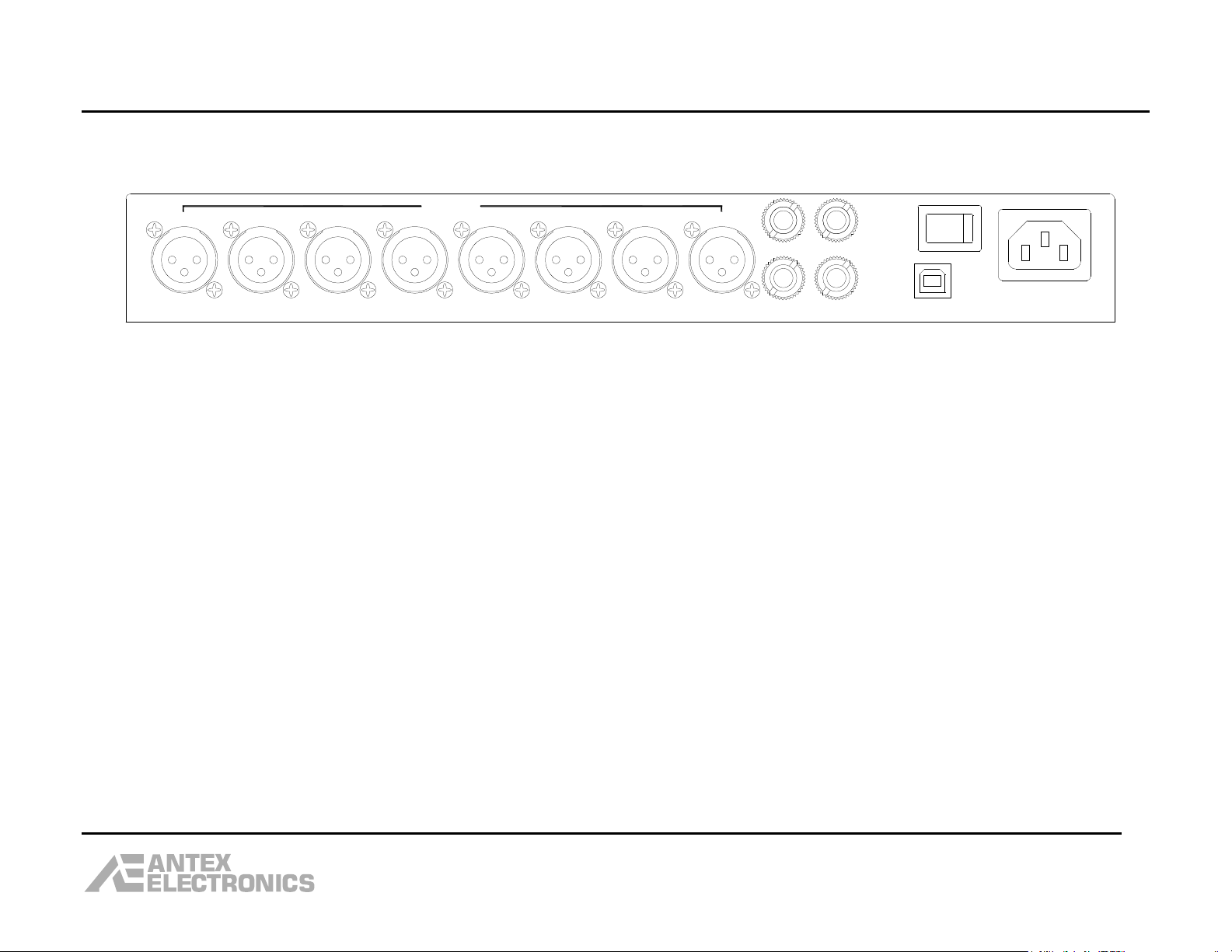
Rear Panel Connections
Inputs 1-8: These are balanced inputs on female XLR connectors and will accept dynamic microphones, condenser microphones and
line level equipment such as video conferencing systems. Each input can be individually configured as line level or microphone level,
with 48 volt phantom power on or off. Microphone setting boosts the gain by 46dB. Phantom power will be disabled if line level is
selected, as phantom power is only intended for use with condenser microphones and may damage line level equipment. Phantom
power is not used with dynamic microphones, but will normally not damage them if turned on. All settings are controlled with the
Antex Mixer Program running on the host computer.
Pin 1 on the XLR connector is ground, pin 2 is hot and pin 3 is cold. To connect unbalanced equipment, a commercial male XLR to
male RCA audio cable can be used. Pin 3 is connected to the outer shell of the RCA jack and pin 2 is connected to the center pin of the
RCA jack. Pin 1 may or may not be connected to pin 3, depending on the type of cable used. A coaxial cable will usually have pins 1
and 3 connected to the shield. A shielded twisted pair will generally connect the shield to pin 1 only. Unbalanced connections are
more prone to pick-up of unwanted hum, so keeping the cable length to less than about 6 feet or 2 meters is recommended.
Mon 1 & Mon 2: These are balanced monitor outputs on female ¼” TRS connectors. Each one can be individually set to be a mix of
any combination of the 8 inputs. The mix is selected in the Antex Mixer Program running on the host computer. These outputs are
typically used to create a “mix minus” signal to feed to a video conferencing or teleconferencing system. The sleeve of the TRS
connector is ground, the ring is cold and the tip is hot. To connect to an unbalanced input, the ring should be connected to the sleeve
and used as the ground connection. The tip is then the signal connection. Using a ¼” TS plug will make this connection automatically.
Use caution when connecting this or any other device to the public telephone network. Do not put too loud a signal level into the
phone line. This could damage telephone equipment and/or be painfully loud to the person on the other end of the phone line.
PA: Public address output. This is a balanced output which can either be an analog mix of all input channels, or a mono mix of the
stereo playback output from the host computer, or a blend of the two. The blend is set by 2 slider controls in the Antex Mixer
6
Page 7

DMX-88 USB Mixer User Manual
Program. The sleeve of the TRS connector is ground, the ring is cold and the tip is hot. To connect to an unbalanced input, the ring
should be connected to the sleeve and used as the ground connection. The tip is then the signal connection. Using a ¼” TS plug will
make this connection automatically.
HP: Headphone output. This output has the identical audio signal as the PA output, but is designed to drive stereo headphones in the
8 ohm to 32 ohm range. The connector is ¼” TRS. The tip and ring are connected to the non-inverting output of the headphone
amplifier and the sleeve is connected to the inverting output of the amplifier. Note: the sleeve is not connected to ground and
must not be connected to ground. Connecting to ground will short out the inverting output of the amplifier and cause
the amplifier to go into thermal shutdown cycling. Also, do not plug in mono headphones (1/4” TS plug) as this will
short the non-inverting and inverting outputs of the amplifier together and cause thermal shutdown cycling.
USB: Connect the DMX-88 to the USB port of the host computer. The USB port must be 2.0 or higher. Note: The DMX-88 is not
intended to be used stand alone. It must be connected to a host computer with the Antex software installed.
AC Power Cord: The DMX-88 uses a standard IEC detachable power cord. It is normally shipped with a USA power cord. If not in
the USA, please use the appropriate power cord for your country. The DMX-88 will operate on any voltage between 90VAC and
240VAC, 50 or 60Hz. Note: Use a grounded power cord and connect to a grounded power outlet. This will protect you
from an electrical shock in the unlikely event that an internal component failure shorts a hazardous voltage to the metal
chassis.
Front Panel LEDs:
Input LEDs: Each input channel has a bicolor LED on the front panel. The LED will light green when there is audio on that channel,
i.e. someone is speaking into the microphone connected to that channel. The LED will light red when the compressor/limiter becomes
active. This indicates the signal is getting too loud. It is OK for the LED to flash red occasionally, but if it is red a large percentage of
the time, this indicates the recording level is set too high. Please see the section on setting the recording level.
Device Number LEDs: These are for future support of multiple DMX-88's connected to one host computer. The current ASIO driver
only supports one DMX-88. There is one green and one red LED to distinguish multiple (up to 4) DMX-88’s connected to one host
computer. The first unit has the red and green LEDs lit, the second has the green LED only lit, the third has the red LED only lit, and
the forth has no LEDs lit. The Antex Mixer Program has mimic LEDs in the upper right, which match the pattern on the unit itself. This
way, the user can tell which instance of the Antex Mixer Program is controlling which DMX-88.
Power LED: The DMX-88 has an energy saving standby mode. When AC power is connected to the unit and the power switch is on,
the power LED will flash about once a second to indicate the unit is in standby mode. Once the USB cable is connected to the host
7
Page 8

DMX-88 USB Mixer User Manual
computer and the DMX-88 enumerates, it will switch to operational mode, and the power LED will stop flashing and be on
continuously. The DMX-88 should go into standby (or suspend) if the USB cable is unplugged or the host PC is shutdown or put into a
sleep state. Note that some operating systems (usually 64 bit), may put the DMX-88 into suspend if there is no software program
using the device.
Other Features:
Compressor/Limiter and Noise Gate: Each input channel has its own compressor/limiter and noise gate. When the audio level is
loud enough, the compressor/limiter will become active. This acts in a way to automatically turn the volume down temporarily. When
this threshold is reached, a 20dB increase in audio level into the compressor/limiter will result in only a 2dB increase in the audio level
out of the compressor/limiter. This will help prevent clipping if someone raises their voice into the microphone, effectively giving
about 20dB more headroom. There is an attack and decay time associated with this function. If the audio level rises suddenl y, the
signal coming out of the compressor/limiter will be loud for a fraction of a second during the attack time, and will then be reduced.
When the compressor/limiter is active, the LED for that channel on the front of the unit will be red. The LED in the Antex Mixer
Program will turn yellow.
The noise gate function reduces the audio level when no one is speaking into the microphone, reducing the “open mic” noise. The
threshold points between when the noise gate is active and when the compressor/limiter is active are about 30dB apart. However,
these thresholds have “soft knees” and turn on gradually. The object is for these functions to improve the quality of the recording
without realizing they are there.
100Hz High Pass Filter: Since the DMX-88 is designed for recording voice rather than music, there is a 100Hz high pass filter on
each input channel to reduce noise that is lower in frequency than the voice range.
Settings Storage: When settings are changed using the Antex Mixer Program, such as input level sliders, these settings are stored in
a non-volatile memory (EEPROM) inside the DMX-88. However, this memory is not updated when the setting is changed, but rather
when the Antex Mixer Program is closed. For this reason, be sure to close the Antex Mixer Program before powering off the DMX-88 or
unplugging the USB cable.
This scheme is different than other Antex products such as the DMX-8 and DMX-4. On these products, the settings are saved in the
registry on the hard drive of the host computer. If you move a DMX-4 or DMX-8 from one computer to another, the settings are not
preserved. The DMX-4 or DMX-8 will be set with the settings saved in the new host computer. With the DMX-88, if you move the unit
from one computer to another, the settings will stay the same.
8
Page 9

DMX-88 USB Mixer User Manual
Installing the Software
Before you can use the DMX-88, you must install the software on the host computer. This includes the "driver" and the DMX-88 Antex
Configuration Program. Note that only an ASIO driver is available and you must have recording software that works with ASIO
devices. There is no WDM driver, and the DMX-88 will not appear as a recording or playback device in Windows Control Panel ->
Sounds.
The operating systems supported are Windows XP, Vista and 7, 32 and 64 bit. Software installation is fairly straightforward, using an
executable installation program available from the Antex web site, www.antex.com, in the 'Downloads" section. The installation
program for 32 bit operating systems is DMX88Mixer32.exe and the program for 64 bit operating systems is DMX88Mixer64.exe.
Run the installation program before connecting the DMX-88 to the host computer. If you connect the DMX-88 first, Windows
will unsuccessfully try to find a driver. When you run the installation program, first you will see:
9
Page 10

DMX-88 USB Mixer User Manual
Click on "Next", and you should see:
10
Page 11

DMX-88 USB Mixer User Manual
Click "Next", and you should see:
11
Page 12

DMX-88 USB Mixer User Manual
Click "Install" and you should see:
12
Page 13

DMX-88 USB Mixer User Manual
Click "Yes" and you should see:
13
Page 14

DMX-88 USB Mixer User Manual
Then you should see:
14
Page 15
DMX-88 USB Mixer User Manual
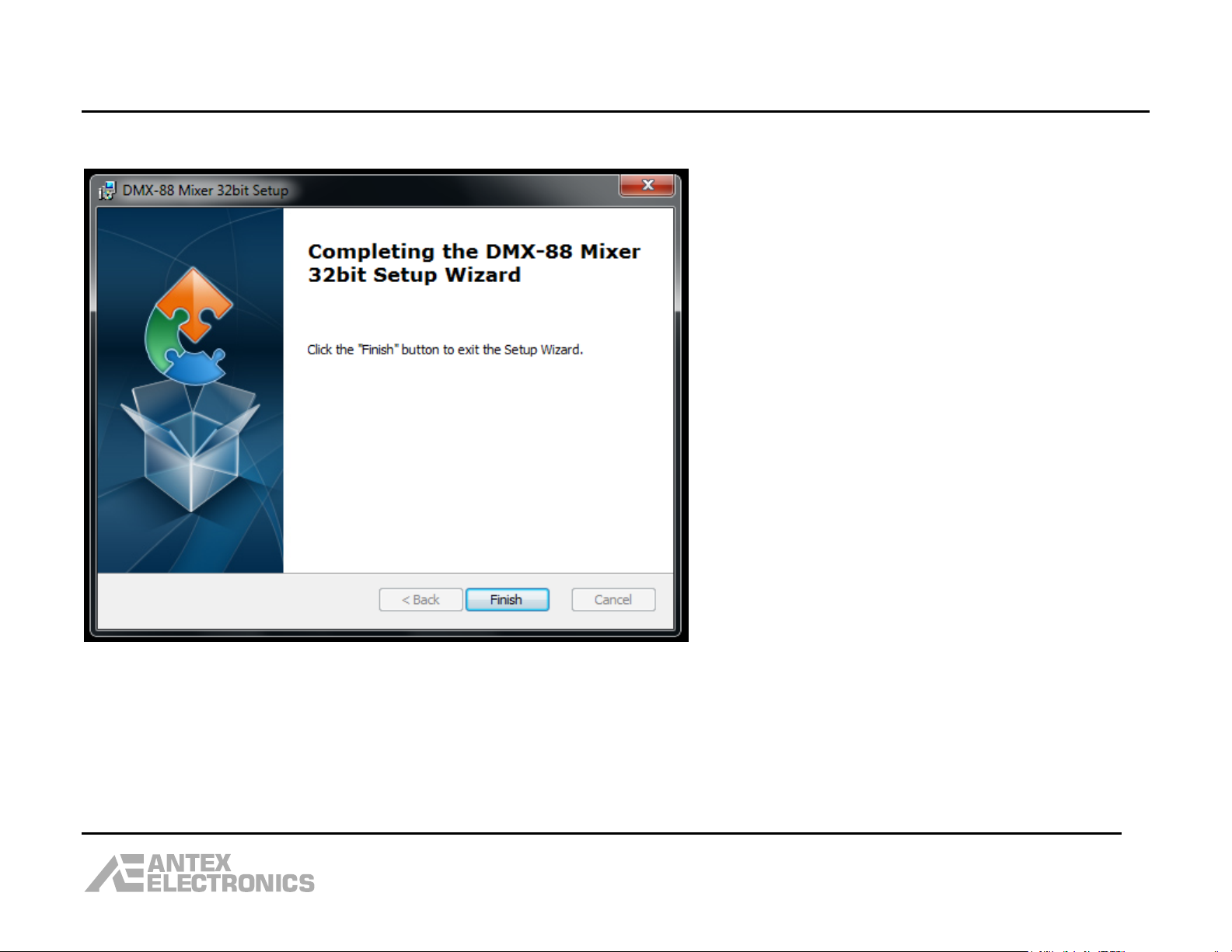
Click on "OK" and you should see:
Click "Finish".
15
Page 16

DMX-88 USB Mixer User Manual
Now you can connect the DMX-88 USB cable to the computer and power it on. You should see:
Followed by:
Also, notice that there is a new shortcut on your desktop for the Antex Mixer program:
16
Page 17

DMX-88 USB Mixer User Manual
Using the Antex Mixer Program
17
Page 18

DMX-88 USB Mixer User Manual
Input Select, Line or Microphone: These 2 buttons set the gain to match the type of input device. They are mutually exclusive,
i.e. turning one on turns the other off. Microphone has 46dB more gain than Line.
Phantom Power: This button turns on or off 48 volt phantom power. This can only be turned on if Microphone is selected because
phantom power may damage line level equipment. Please consult the specifications of your microphone to see if phantom power is
required.
Monitor Channel: These buttons select whether or not that particular input channel is part of the mix for the selected monitor
channel. In the screen shot shown above, Monitor 1 is a mix of Inputs 1-6 and 8. Monitor 2 is a mix of Inputs 1-7.
Input Level: There is one slider control for each Input channel to control the recording level. Under each slider is the setting in dB.
To adjust a slider, move the mouse pointer over the slider knob and click and hold the left mouse button down and drag the slider
knob up or down. Or, you can move the mouse pointer over the slider knob and click the left mouse button once to set the “focus” on
the slider. Then, either use the up and down arrows on the keyboard or the scroll wheel on the mouse to adjust the slider. This
second method gives you finer control.
Sample Rate: This box shows the current sample rate setting. You cannot change the sample rate. This is set by your recording
software. If the sample rate is not what you expect, try opening your recording software and turning on the record monitor to see if
the sample rate changes.
Input LED: These indicator boxes have 4 colors; gray (off), green, yellow, and red. Green indicates audio activity; i.e. someone is
speaking into the microphone. If the indicator turns yellow, this means the threshold for the compressor/limiter has been reached. It
is OK for the indicator to be yellow occasionally. If the indicator turns red, this means the front end of the preamp is clipping. This
should not happen and cannot be corrected by moving the Input Level slider. If this happens, make sure you do not have the
Microphone setting on when you have Line Level equipment connected. If using Line Level equipment, see if there is an adjustment to
lower the output level. If the indicator turns red when using a microphone, the output of the microphone is too hot. Try moving the
microphone further away from the person speaking or installing a pad between the microphone and the DMX-88.
Monitor Level: These sliders adjust the output level of the Monitor outputs. Under each slider is the setting in dB. To adjust a
slider, move the mouse pointer over the slider knob and click and hold the left mouse button down and drag the slider knob up or
down. Or, you can move the mouse pointer over the slider knob and click the left mouse button once to set the “focus” on the slider.
Then, either use the up and down arrows on the keyboard or the scroll wheel on the mouse to adjust the slider. This second method
gives you finer control. Use care not to turn the level up too loud when the monitor output is connected to a teleconferencing system,
This may damage telephone equipment and/or be painfully loud to the person on the other end of the phone line.
18
Page 19

DMX-88 USB Mixer User Manual
Monitor All Level and Playback Level: These 2 sliders control the loudness and signal mix coming out of the Headphone (HP) and
Public Address (PA) outputs. These 2 outputs are not independently controllable; the sliders will change the level in both outputs at
the same time. The Monitor All signal is an analog mix of all 8 inputs. The Playback signal comes from the host computer, if your
recording software supports this feature.
Input and Monitor Labels: These text boxes allow you to type in a label for the input channels and the two monitor channels to
indentify them. These labels will be saved in non-volatile memory in the DMX-88 when the Antex Mixer Program is closed. The labels
will also be part of a “scene” file if saved.
VU Meters: There is one vu meter for each input channel. Note that the meter will only be active when recording software is either
recording or monitoring.
Device Number LEDs: These two LEDs mimic the two Device Number LEDs on the DMX-88 front panel. This will help determine
which instance of the Antex Mixer Program is controlling which DMX-88 if more than one DMX-88 is connected to the same host
computer.
Scenes Open and Save As: These two buttons allow you to save the current mixer settings to a scene file or to restore mixer
settings from a previously saved scene file. Scene files are saved on the host computer hard drive. The settings saved in the scene
file include the Input and Monitor labels, the slider settings and all the button settings.
Adjusting the Recording Level
Having the proper recording level is essential to making good, intelligible recordings. If the level is too low, the recording will contain
a lot of hiss when it is played back loud enough to hear. If the level is set too high, loud sounds or speech will “clip” and the sound will
be distorted. Clipping occurs when the level of the signal being digitized exceeds the maximum level of the analog to digital converter.
The compressor/limiter circuit in the DMX-88 effectively gives almost 20dB more headroom to accommodate unexpected loud sounds
without clipping.
The VU meters in the Antex Mixer Program are used to adjust the recording level. Note that the meters are only active when a
recording program is monitoring or recording. As a rule of thumb, speak at a normal level into the microphone. Adjust the
Input Slider on the Antex Mixer Program until the VU meter peaks are in the –10 to –15dB range. Also, observe the LEDs on the front
panel of the DMX-88 or the LEDs below the Input Level sliders in the Antex Mixer Program. They should be green when speaking at
the normal level. When someone raises their voice, the LED on the front panel may flicker red (the corresponding LED in the Antex
Mixer Program will flicker yellow).
19
Page 20

DMX-88 USB Mixer User Manual
-95dB TO +31.5dB
HPF
100Hz
HPF
100Hz
HPF
100Hz
CH8 OUT
LIMITER/
NOISE GATE
A/D
A/D
CH1 OUT
-95dB TO +31.5dB
CH2 OUT
A/D
HPF
100Hz
LIMITER/
NOISE GATE
USB 2.0
CH7
PB_RIGHT
PB_LEFT
A/D
CH5
-95dB TO +31.5dB
CH4
LIMITER/
NOISE GATE
LIMITER/
NOISE GATE
CH4 OUT
LIMITER/
NOISE GATE
CH3 OUT
+
-
LINE=0dB, MIC=+46dB
CH3
CH1
A/D
+
-
LINE=0dB, MIC=+46dB
LIMITER/
NOISE GATE
+
-
LINE=0dB, MIC=+46dB
+
-
LINE=0dB, MIC=+46dB
CH6
D/A
+
-
LINE=0dB, MIC=+46dB
CH5 OUT
-95dB TO +31.5dB
+
-
LINE=0dB, MIC=+46dB
-95dB TO +31.5dB
A/D
-95dB TO +31.5dB
CH8
A/D
-95dB TO +31.5dB
USB ENGINE
D/A
LIMITER/
NOISE GATE
HPF
100Hz
HPF
100Hz
HPF
100Hz
CH7 OUT
CH6 OUT
HPF
100Hz
+
-
LINE=0dB, MIC=+46dB
LIMITER/
NOISE GATE
CH2
A/D
-95dB TO +31.5dB
+
-
LINE=0dB, MIC=+46dB
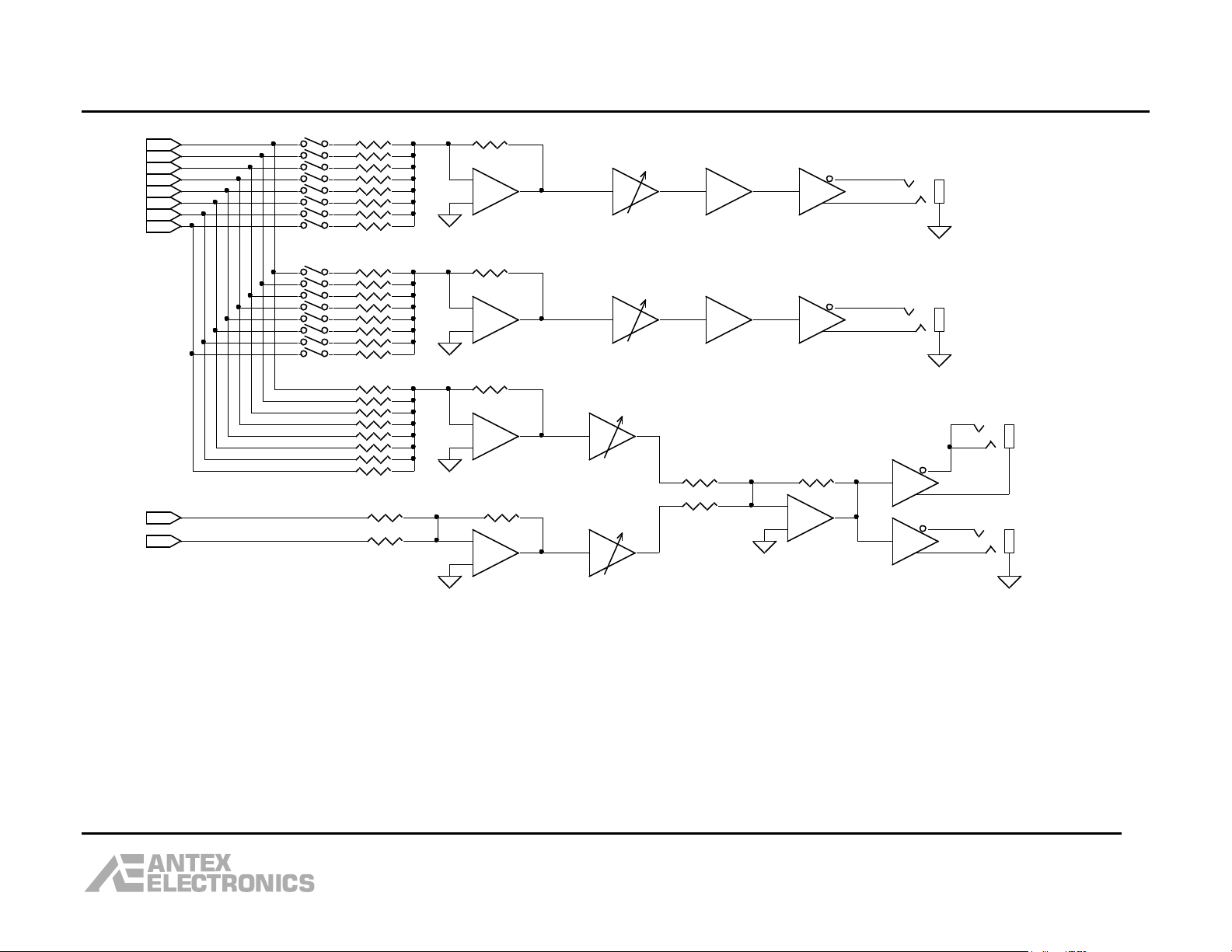
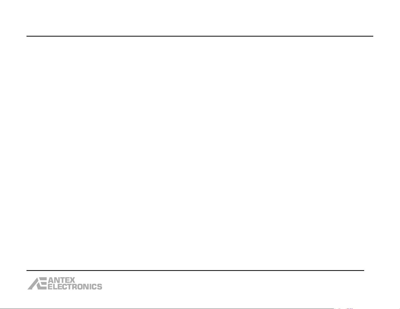
Block Diagram
20
Page 21
MONITOR 1
+10dB
CH4 OUT
+
-
+
-
+
-
CH6 OUT
CH1 OUT
MONITOR 2
PLAYBACK
CH3 OUT
-95dB TO +31.5dB
HEADPHONE
-95dB TO +31.5dB
MONITOR ALL
CH2 OUT
CH8 OUT
-95dB TO +31.5dB
-95dB TO +31.5dB
CH7 OUT
+10dB
CH5 OUT
+
-
PB_RIGHT
+
-
PA
PB_LEFT
DMX-88 USB Mixer User Manual
21
Page 22

DMX-88 USB Mixer User Manual
Attaching Rack Mount Ears
The rack ears are attached to the sides of the DMX-88 using three 6-32 by 3/8” long screws. There are 4 holes in the rack ears so
that the left and right ears are identical, even though only 3 holes are used. When rack mounting the DMX-88, remove the 4 rubber
feet from the bottom of the unit.
22
Page 23
DMX-88 USB Mixer User Manual
Specifications:
Inputs:
Number ------------------------------------------------------------------------------------ 8
Type ---------------------------------- Transformerless balanced (instrumentation amp)
Connector --------------------------------------------------------------------- Female XLR
Impedance to ground ------------------------------------------------------------------- 1K
Sensitivity, Line setting -------------------------------------------------------- -31dBV
Sensitivity, Microphone setting ------------------------------------------------ -77dBV
(Sensitivity is the input signal level which corresponds to A/D full scale with the input
trim set to maximum gain. Note that full scale A/D may not be possible because the
limiter becomes active approximately 10dB below full scale.)
Maximum input level before transient protection begins clipping ------------ +21dBV
Limiter threshold ---------------------------------------------------- 10dB below full scale
Limiter headroom -------------------------------------------------------------------- 20dB
Noise gate threshold ------------------------------------------------ 40dB below full scale
(Note that the limiter and noise gate thresholds are “soft”.)
Phantom power voltage ---------------------------------------------------------------- 48V
Phantom power impedance ------------------------ 6.8K on hot and cold, 3.4K effective
Trim control type -------------------------------------------------- Electronic (solid state)
Trim control step size ---------------------------------------------------------------- 0.5dB
High pass filter -------------------------------------------- 100Hz, 12dB per octave slope
Monitor Outputs:
Number ------------------------------------------------------------------------------------ 2
Type ------------------------------------------------------------ Transformerless balanced
(Note: May be used as unbalanced by grounding one of the signal lines.)
Connector -------------------------------------------------------------------------- ¼” TRS
Mix ------------------------------------------------------- Any combination of the 8 inputs
Level control type ------------------------------------------------- Electronic (solid state)
Level control step size --------------------------------------------------------------- 0.5dB
Maximum output level -------------------------------------------------------------- 21dBV
23
Page 24

DMX-88 USB Mixer User Manual
Headphone Output:
Connector -------------------------------------------------------------------------- ¼” TRS
Output power ----------------------------------------- 500mW (16 ohm load, THD = 1%)
Source -------------------------------------------- D/A output or analog mix of all inputs
Level control type ------------------------------------------------- Electronic (solid state)
Level control step size --------------------------------------------------------------- 0.5dB
PA Output:
Connector -------------------------------------------------------------------------- ¼” TRS
Type ------------------------------------------------------------ Transformerless balanced
(Note: May be used as unbalanced by grounding one of the signal lines.)
Source -------------------------------------------- D/A output or analog mix of all inputs
Level control type ------------------------------------------------- Electronic (solid state)
Level control step size --------------------------------------------------------------- 0.5dB
Maximum output level -------------------------------------------------------------- +7dBV
Digital audio:
Number of record channels --------------------------------------------------------------- 8
Number of playback channels ------------------------------------------------------------ 2
Bit depth --------------------------------------------------------------------------------- 24
Sample rates ---------------------------- 8, 11.025, 12, 16, 22.05, 24, 32, 44.1, 48KHz
USB:
Specification -------------------------------------------------------------- 2.0, high speed
Audio data transfer packet type ------------------------------------------------------ Bulk
Control data packet type -------------------------------------------------------- Interrupt
24
Page 25

DMX-88 USB Mixer User Manual
Software:
ASIO driver only, for Windows XP, Vista, and 7; 32 and 64 bit. Graphical User Interface "DMX-88 Antex Configuration" program
provided.
Indicators:
On unit, red/green LED for each input. Green indicates activity, red indicates limiter active.
Power LED
Red and Green Device Number LEDs
Power:
Internal power supply with detachable IEC cord, 90-240 VAC.
Dimensions:
13 inches wide, 10 inches deep, Max height 1U (1.75 “). Rack ears optional for 19 inch rack mounting.
Weight:
3.6 pounds, 3.85 pounds with rack ears
Note: Specifications may be subject to change without notice.
Technical Assistance
Technical assistance with this product is available from Antex via:
email: asupport@antex.com
Web: www.antex.com
Phone: (310) 532-3092, ext 17, 7AM to 5PM PDT
25
Page 26

DMX-88 USB Mixer User Manual
12 Month Limited Warranty
Antex Electronics Corporation (the Company), warrants to the original purchaser of this product that should this product or any part thereof, under
normal use and conditions, be proven defective in material or workmanship within 12 months of the original date of purchase, such defect(s) will be
repaired or replaced with new or reconditioned product (at the Company’s option) without charge for parts and labor.
To obtain repair or replacement within the terms of this Warranty, the product is to be delivered with proof of warranty coverage (i.e. dated sales
receipt), specification of the defect(s), and transportation prepaid to the Company at the address shown below.
This Warranty does not extend to the elimination of externally generated static or noise, to correction of antenna problems, to costs incurred for
installation, removal or reinstallation of the product, or damage to other components.
This Warranty does not apply to any product or part thereof which, in the opinion of the Company, has suffered or been damaged through alteration,
improper installation, mishandling, misuse, neglect, accident, or by removal of any factory applied markings. THE EXTENT OF THE COMPANY’S
LIABILITY UNDER THIS WARRANTY IS LIMITED TO THE REPAIR OR REPLACEMENT PROVIDED ABOVE, AND, IN NO EVENT, SHALL THE COMPANY’S
LIABILITY EXCEED THE PURCHASE PRICE PAID BY PURCHASER FOR THE PRODUCT.
This Warranty is in lieu of all other express warranties or liabilities. ANY IMPLIED WARRANTIES, INCLUDING AN IMPLIED WARRANTY OF
MERCHANTABILITY, SHALL BE LIMITED TO THE DURATION OF THIS WRITTEN WARRANTY. ANY ACTION FOR BREACH OF ANY WARRANTY
HEREUNDER INCLUDING ANY IMPLED WARRANTY OF MERCHANTABILITY MUST BE BROUGHT WITHIN A PERIOD OF 12 MONTHS FROM DATE OF
ORIGINAL PURCHASE. IN NO CASE SHALL THE COMPANY BE LIABLE FOR ANY CONSEQUENTIAL OR INCIDENTAL DAMAGES FOR BREACH OF THIS OR
ANY OTHER WARRANTY, EXPRESS OR IMPLIED, WHATSOEVER. No person or representative is authorized to assume for the Company any liability
other than expressed herein in connection with the sale of this product.
Some states do not allow limitations on how long an implied warranty lasts or the exclusion or limitation of incidental or consequential damage so the
above limitations or exclusions may not apply to you. This Warranty gives you specific legal rights and may also have other rights, which vary from
state to state.
Antex Electronics Corporation
19160 S. Van Ness Avenue
Torrance, CA 90501
(310) 532-3092
26
 Loading...