

Page 1

DMX8 USB Mixer
Installation Guide
Page 2

TRADEMARKS
y
d
gy
k
y
FTR, FTR Gold and ForTheRecord are registered trademarks of FTR, Ltd. and/or FTR Pty Ltd.
FTR Reporter, FTR Player Plus, FTR Save-To-Tape, FTR Save-To-Forma t, FTR CD Player, FTR Log Notes,
FTR CD, FTR Open-From-ForTheRecord, FTR Monitor, ForTheRecord.com, FTR Portable Reporter and
FTR ReporterDeck are either registered trademarks or trademarks of FTR, Ltd. and/or FTR Pty Ltd.
Microsoft and Windows are either registered trademarks or trademarks of Microsoft Corporation in the United
States and/or other countries.
All other brand and product names are trademarks or registered trademarks of their respective companies.
DISCLAIMER
FTR Pty Ltd makes a sincere effort to ensure the accuracy of the material desc ri bed herein; however, except as set
forth in the license documentation applicable to each product of FTR Pty Ltd. makes no warranty, express or
implied, with respect to the quality, correctness, reliability, currentness, accuracy, or freedom from error of this
document or the products referred to herein, and specifically disclaims any implied warranties of merchantability
and fitness for any particular purpose. FTR Pty Ltd disclaims all liability for any direct, indirect, incidental,
consequential, special or exemplary damages resulting from the use of the information in this document or from the
use of any products described in this document. Mention of any product not manufactured by FTR Pty Ltd does
not constitute an endorsement by FTR Pty Ltd of that product.
COPYRIGHT NOTICE
This manual is copyrighted and all rights are reserved by FTR Pty Ltd. No part of this publication may be
reproduced, transmitted, transcribed, stored in a retrieval system, or translated into any language or computer
language, in any form or by any means, electronic, mechanical, magnetic, optical, chemical, manual, or otherwise,
without the prior written permission of FTR Pty Ltd.
If this manual has been supplied by FTR Pty Ltd in Adobe® Acrobat® portable document format (pdf) then
FTR Pty Ltd grants permission for a single copy to be printed in its entirety.
FTR Pt
Ltd FTR Pty Lt
Suite 7 PO Box 1048
16 Brodie Hall Drive Technolo
Par
Technology Park Bentle
Bentley Western Australia 6983
Western Australia 6102
Copyright © 1998 - 2005
All Rights Reserved
FTR-InstallationGuide-DMX8.doc 20051222
ii
Page 3

Safety Notices
Please read the following instructions and safety notices before installing this equipment.
Voltage Selection
Depending on the equipment you purchased it may be necessary to change the operating
voltage for your region. The power connector on the rear panel of the equipment may
have a voltage selection switch. Check the voltage setting and change if required. If no
voltage selection switch is available then the power supply is auto-sensing and you do not
need to select an operating voltage.
Warning This equipment is designed to operate while connected to a grounded
!
wall outlet. Always use a power cable with a properly grounded plug such as the
one provided with this equipment. To reduce the risk of electric shock, never
disable this important safety feature.
Canadian Deviations clause 1.1.1
All equipment installations are required to be in accordance with the Canadian Electrical
Code (CEC), Part 1, CAN/CSA C22.1
US Deviations clause 1.1.1
All equipment installations are required to be in accordance with the National Electrical
Code (NEC) ANSI/NFPA 70, and, unless marked or otherwise identified, the Standard for
the Protection of Electronic Computer/Data-Processing Equipment, ANSI/NFPA 75.
Warning Only qualified technical service personnel should open the case of
!
this equipment. All user accessible connections and controls are located on the
front or rear panels of the equipment. Opening the case may also void your
warranty. If you need to make changes that require the case to be opened, contact
your authorized FTR service center.
iii
Page 4

Table of Contents
Safety Notices .........................................................................................................................................iii
DMX8 USB Mixer................................................................................................................................... 1
Product Outline ....................................................................................................................................1
System Requirements........................................................................................................................... 1
Installing the DMX8 USB Mixer ........................................................................................................... 2
Voltage Selection.................................................................................................................................2
Location ............................................................................................................................................... 2
Environment......................................................................................................................................... 3
Connections.......................................................................................................................................... 3
Installing the DMX8 USB Mixer ........................................................................................................... 5
Installation............................................................................................................................................ 5
Configuring Windows® Multimedia Settings .................................................................................... 10
Completing the Installation.................................................................................................................. 11
TheRecord Recorder .......................................................................................................................... 11
FTR Reporter ..................................................................................................................................... 11
Configuring the DMX8 USB Mixer..................................................................................................... 13
Controls.............................................................................................................................................. 13
Adjusting Levels ................................................................................................................................15
Scenes ................................................................................................................................................ 17
About DMX8 Configuration................................................................................................................ 19
DMX8 Meter ......................................................................................................................................... 21
Troubleshooting.................................................................................................................................... 22
Specifications......................................................................................................................................... 24
Appendix A............................................................................................................................................ 26
Diagram 1 – DMX8 Front and Rear Panels....................................................................................... 26
iv
Page 5

DMX8 USB Mixer
This guide provides general information for the installation and configuration of the
DMX8 USB Mixer.
Product Outline
The DMX8 USB Mixer is a general purpose automatic audio mixer allowing eight
microphone or line inputs to be connected and mixed to one to four digital recording
outputs. The recording outputs are delivered to a computer through a Hi-Speed USB port
connection. Additionally, the DMX8 USB Mixer has four monitor outputs allowing the
inputs to be routed to the outputs in any combination required. A further Mono output
provides a mixdown of all eight inputs.
The simplicity of the USB connection mechanism and the excellent audio performance of
the DMX8 USB Mixer ensure it is compatible with a wide variety of digital recording
environments.
System Requirements
Windows® 2000 SP4 -or-
Windows® XP Home SP1 or greater, -or-
Windows® XP Professional SP1 or greater
Computer with Hi-Speed USB (USB 2.0) Interface
Page 1
Page 6

Installing the DMX8 USB Mixer
Before commencing an installation make sure you have the following:
DMX8 USB Mixer
DMX8 USB Mixer CD or Software downloaded from www.fortherecord.com
DMX8 USB Mixer Installation Guide (this guide)
Hi-Speed rated USB cable to connect DMX8 USB Mixer to computer (supplied)
Power cable suitable for your region (supplied)
Microphones
Microphone cables wired correctly for the DMX8 XLR connectors
Voltage Selection
Before connecting the equipment to mains power, be sure to select the correct
operating voltage for your region.
1. Remove the power cable from the equipment.
2. Slide the voltage selector switch located under the power inlet socket to the correct
setting.
3. Check that the required voltage is now visible on the voltage selector switch.
4. Re-insert the power cable.
Location
The DMX8 USB Mixer can be mounted on a tray in a 19” rack or placed on a shelf or
table. All connections are from the rear panel (see Appendix A Diagram 1).
Ideally the DMX8 USB Mixer should be located inside the room where recording will
take place however it can be located outside if due consideration is given to microphone
and output cable lengths and electrical interference.
The DMX8 USB Mixer must be located close to the computer it is connected to. HiSpeed USB has a connection length limit of 16 feet (5 meters).
Page 2
Page 7

Environment
The DMX8 USB Mixer should be installed in a clean, dust free, location that will allow
free air to circulate around it for cooling purposes. Overly hot, closely enclosed, humid,
dirty or dusty environments should be avoided. Having decided on a suitable location for
the DMX8 USB Mixer, read the following section when installing and connecting
equipment.
Connections
Connecting the equipment involves the placement and connection of microphones or other
input devices and cables, connection to a computer and any monitoring equipment and the
testing of the complete system.
Microphones
Place microphones as close as practical to the users but avoid restricting their view of the
room. Be aware of the need for space to place papers and books without knocking or
covering the microphone.
Ensure microphones are a minimum of 3 feet (1 meter) from sources of electronic
interference such as the DMX8 USB Mixer, computer and lighting.
Microphone Cables
Connect the cabling between the microphones and the DMX8 USB Mixer. If possible
conceal and secure the cables to prevent them from being damaged or entangled by users.
Avoid placing cables near possible sources of interference such as power cables, lights,
monitors and computers. When connecting microphone cables do not lay the cables under
or over the DMX8 USB Mixer. They must lead directly away.
Recording Equipment
Connect the USB output of the DMX8 USB Mixer directly to an available Hi-Speed USB
interface on your computer. Do not connect the DMX8 USB Mixer to the computer via a
hub or repeater. You will require a Hi-Speed rated USB cable like the one supplied with
the DMX8 USB Mixer to make this connection.
Monitoring Equipment
The Monitor outputs on the DMX8 USB Mixer may be used for a range of different
purposes including telephone and/or video conferencing, public address via an amplifier
Page 3
Page 8

and/or powered speakers or for an analog audio feed for backup or other archival
requirements.
Testing
Have another person speak into each microphone at normal to loud levels. Watch the
corresponding Input Level LED on the front panel of the DMX8 USB Mixer. As each
microphone is tested the LED should flash green. It is acceptable for the LED to flash red
occasionally with loud speech. If the microphones are placed close together the voice test
should be accompanied by a “scratch” test. Before speaking, lightly scratch each
microphone and observe which LED on the front panel lights. This ensures the correct
microphone is being tested. If devices other than microphones are connected to the inputs
of the DMX8 USB Mixer, perform a similar test on these devices.
After the drivers and the DMX8 Configuration are installed use the configuration program
to adjust the recording and monitoring levels. See the Configuring the DMX8 USB Mixer
section later in this guide.
Page 4
Page 9

Installing the DMX8 USB Mixer
Note:
!
When you insert the DMX8 USB Mixer CD, the Setup program will determine if
your system meets the minimum software requirements for this product.
If your system does not meet these requirements, the Setup program will provide onscreen
instructions advising which software or upgrades are required. Make sure to print out the
instructions, as you may need to use these as a reference during the installation procedure.
Installation
The DMX8 USB Mixer is supplied with a CD containing drivers, a configuration
program, a meter program and an electronic version of this guide. The following steps
detail the procedures for installing the software.
Please Note: It is important to turn the mixer off before commencing
installation.
Installing the DMX8 USB Mixer software
1. Insert the installation CD into your CD-ROM drive. If the autorun does not start,
double-click DMX8Setup.exe
Page 5
Page 10
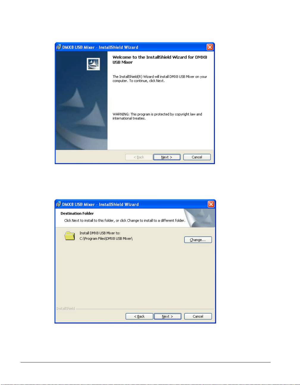
From the Welcome to the InstallShield Wizard dialog box click Next.
2. From the Destination Folder dialog box click Next to continue, or click Change
to install to a different folder.
Page 6
Page 11

3. From the Ready to Install the Program dialog box click Install.
Note: An installation progress box will appear briefly.
4. From the InstallShield Wizard Completed dialog box click Finish.
Page 7
Page 12

5. From the DMX8 Configuration Access dialog box select Yes to permit access to
the current user only or No to permit access to all users.
6. To continue with the installation of the DMX8 USB Mixer:
a. Ensure the DMX8 is switched off at the power outlet.
b. Click OK when the power is off.
Page 8
7. To complete the installation of the DMX8 USB Mixer:
a. Ensure the DMX8 is connected to the computer via a USB cable.
b. Power up the DMX8 by switching it on at the power outlet.
c. Click OK when the power is on.
Page 13

Note: The installation is not complete. Wait for the Found New Hardware
Wizard dialog box for the Antex Electronics USB FTR Mixer Device and
other hardware to be displayed.
8. Windows XP detects the Antex Electronics USB FTR Mixer Device and other
hardware.
9. From the System Settings Change dialog box click Yes to restart your computer.
IT IS IMPORTANT TO RESTART YOUR COMPUTER NOW, EVEN IF
YOU ARE NOT PROMPTED TO DO SO.
Page 9
Page 14

Configuring Windows® Multimedia Settings
During the installation of the DMX8 USB Mixer, Windows multimedia settings may be
configured in a way that is unsuitable for use with FTR Reporter or TheRecord Recorder.
It is good practice to check the multimedia settings and make adjustments as required.
These settings need to be checked for each user account that is to use FTR Reporter or
TheRecord Recorder.
Ensure that your stereo sound card and drivers for playback are installed and functioning
properly. Refer to the vendor documentation for installation instructions.
To check and adjust Windows multimedia settings:
1. Click Start then click Control Panel.
2. Click Sounds, Speech and Audio Devices.
3. Click Sounds and Audio Devices and select the Audio tab.
Page 10
4. In the Sound playback section select the standard stereo sound card of your
computer as the playback device from the Default device list.
of the Antex USB FTR Wave devices for this playback setting.
5. Click OK.
6. Proceed to the Completing the Installation section of this guide.
7. Repeat these steps for each user account that is to use FTR Reporter or TheRecord
Recorder.
Do not select any
Page 15

Completing the Installation
To complete the installation follow the instructions relevant to your recording software,
FTR Reporter or TheRecord Recorder.
TheRecord Recorder
To complete the installation of the DMX8 USB Mixer:
1. Ensure that the DMX8 USB Mixer is connected to the computer using the
supplied Hi-Speed USB cable.
2. Install the TheRecord Recorder software. Start TheRecord Recorder, and from the
Tools menu click Options. Click the Multimedia tab and select from the
following settings:
a. For 1 or 2 channel recording select 1-Antex USB FTR/1 Wave.
b. For 4 channel recording select DMX8 USB Mixer.
Note: See the TheRecord Recorder User’s Guide for further details.
FTR Reporter
To complete the installation of the DMX8 USB Mixer:
1. Ensure that the DMX8 USB Mixer is connected to the computer using the
supplied Hi-Speed USB cable.
2. Install the FTR Reporter software and run the Settings Wizard. See the
FTR Reporter User’s Guide, and the Running the FTR Reporter Settings Wizard
section below, for details.
Running the FTR Reporter Settings Wizard
Run the Settings Wizard to configure FTR Reporter to record with the DMX8 USB Mixer.
To run the Settings Wizard:
1. Click Start, point to Programs, then FTR Gold then click Settings Wizard.
2. Follow the prompts and the FTR Reporter User’s Guide instructions for running
the Settings Wizard. After selecting the Number of Recording Channels and
Format, the following message is displayed.
Page 11
Page 16

3. Click OK and complete the Settings Wizard.
Page 12
Page 17

Configuring the DMX8 USB Mixer
To open the DMX8 Configuration:
• Click Start, point to All Programs, navigate to the DMX8 USB Mixer folder and click
DMX8 Configuration.
Tip: You can create a shortcut on your desktop to open the DMX8 Configuration.
Controls
Settings
Input Select
For each input select the type of input device. The options available are:
• Line - for equipment that works at nominal line level
• Dynamic - for dynamic microphones
• Condenser - for condenser microphones
Page 13
Page 18

Phantom Power
Can be selected if a condenser microphone is connected to the input.
Recording Channel
For 1 channel recording switch all inputs to Recording Channel 1.
For 2 channel recording switch inputs to Recording Channel 1 or 2 as required.
For 4 channel recording switch inputs to Recording Channels 1-4 as required.
Monitor Channel
Select the Monitor channel that the input will be mixed to.
Input Level
Adjust the level of each input.
Recording Channel Level
Adjust the level of each Recording channel.
Monitor Channel Level
Adjust the level of each Monitor channel.
Page 14
Page 19

Adjusting Levels
It is important to adjust the DMX8 USB Mixer inputs and outputs to achieve optimum
audio recording levels. The steps below describe the process that should be used for all
inputs and outputs to achieve this. The Input Levels must be adjusted before adjusting the
Recording Channel Levels or the Monitor Channel Levels.
Adjusting Input Levels:
1. Connect microphones or line sources to the DMX8 USB Mixer inputs.
2. For each input select the appropriate input type (Line, Dynamic, or Condenser)
using the Input Select buttons. If Condenser is selected and phantom power is
required by the microphone click the Phantom Power button for the input to turn
phantom power on.
3. Start with all the Input Level sliders set to 0dB.
4. For each microphone input talk loudly into the microphone at a distance of 12
inches, or for each line input provide a line level signal of nominal level. View
the front panel indicator LED for the appropriate input, and adjust the Input
Level slider such that the LED lights green constantly and occasionally turns red.
If you are unable to achieve this condition then check you have the correct input
selection for the input type being used.
Adjusting Recording Channel Levels:
The recording channel level is the signal level being converted to digital format and is
recorded by the computer.
Note: Recording Channel Levels must be adjusted after the Input Levels are adjusted.
1. Use the Recording Channel buttons to select the recording channels that each
input will be mixed to. Each input can be mixed to any of the 4 recording
channels. If you are recording 1 or 2 channels only, select recording channel 1
and/or 2 as appropriate for each input.
2. For each recording channel adjust the Recording Channel Level slider. It is
important to adjust these sliders so that an adequate signal level well above any
background noise but below the clipping threshold is obtained. To adjust the
recording channel levels:
a. Use your recording software to start a recording.
b. Start with all the Recording Channel Level sliders set to 0dB.
Page 15
Page 20

c. Adjust these sliders so that when talking loudly into a microphone at a
distance of 12 inches or providing a line level signal of peak amplitude,
the meters light all bars including the occasional red bar at the top of the
scale. It is important to get this setting as high as possible with only
occasional indications of the red bar lighting.
Adjusting Monitor Channel Levels:
1. Use the Monitor Channel Buttons to select the monitor outputs for each input.
Each input can be mixed to any of the 4 monitor channel outputs. The
configuration of the Monitor Channel output may differ from the configuration of
the Recording Channels if required. This is useful in cases where teleconferencing
is required or where a public address system is in place and feedback needs to be
avoided.
2. For each monitoring channel adjust the Monitor Channel Level slider. Care
should be taken not to overdrive external equipment with these signals. Start by
setting these sliders 10dB lower than the average Recording Channel Level
setting, and connect to external equipment such as speakers, teleconferencing
system, or other devices. Adjust these sliders for each output to provide
appropriate volume levels at the external equipment.
Page 16
Page 21

Scenes
With the DMX8 Configuration you can save and open different configuration ‘scenes’,
making the DMX8 USB Mixer quick to configure for different situations.
Saving a scene:
1. Click the Save As… button on the DMX8 Configuration.
2. From the Save As… dialog box select a save location from the Save in: list and
enter a File name for the scene. Click Save.
Note: The file is saved with a file extension .scene.
Page 17
Page 22

Opening a scene:
1. Click the Open button on the DMX8 Configuration.
2. From the Open dialog box use the Look in: list to navigate to the scenes save
location and click the required scene. Click Open.
Page 18
Page 23

About DMX8 Configuration
If you need to contact your vendor about a problem operating the DMX8 USB Mixer, you
may be asked to supply the version number.
To locate the version number from DMX8 Configuration:
3. Click the ForTheRecord icon in the title bar to show the system menu and click
About DMX8 Configuration….
4. From the About DMX8 Configuration dialog box note the version information
and then click OK to close the dialog box.
To locate the version number from DMX8 Meter:
1. Click the ForTheRecord icon in the title bar to show the system menu and click
About DMX8 Meter…
Page 19
Page 24

From the About DMX8 Meter dialog box note the version information and then
2.
click OK to close the dialog box.
Page 20
Page 25

DMX8 Meter
The DMX8 Meter displays the recording input level while recording is in progress using
FTR Reporter or TheRecord Recorder.
The Meter allows users who are not permitted access to the DMX8 Configuration to
monitor recording levels.
The DMX8 Meter can be started by double-clicking the DMX8 Meter icon on your
desktop.
Page 21
Page 26

Troubleshooting
The following information is a guide to solving simple problems that you may encounter
during the installation, testing and normal operation of the DMX8 USB Mixer and
associated equipment. If you cannot solve the problem using this information contact
your vendor.
Issue Steps to Correct
The power LED on the front panel is
not lit.
Input Level LED does not illuminate
when a microphone is tested.
Sound is distorted in your recording
computer.
Check the power cable is firmly plugged
into the power socket. Check the cable is
plugged into the power outlet and that power
is switched on.
Check that the relevant microphones and
cables are correctly plugged in. Ensure the
cables are wired to correct standards. Check
the input level settings on the DMX8
Configuration are set to the correct values
(Dynamic/Condenser and Phantom Power).
If the problem persists swap the microphone
for a known good one.
If the problem persists swap the cable for a
known good one.
If the problem persists contact your vendor.
Check and adjust the input and recording
channel levels using the DMX8
Configuration.
Distortion is usually caused when the input
or recording level is set too high.
Ensure the input type is correct for the type
of microphone you are using.
Page 22
Page 27

Issue Steps to Correct
Hum or buzz in the recording. Usually caused by electrical interference to
the microphones or cables. Ensure all cables
and microphones are moved away from
possible sources of interference such as
computers, monitors, mixers and lighting.
If the problem persists disconnect all
microphone cables. Re-connect each
microphone cable until the buzz returns.
Replace the cable and/or microphone that
introduces the buzz.
Low recording level on one channel. Check and adjust the input and recording
levels using the DMX8 Configuration.
Check microphone placement.
Swap for a known good microphone. If the
problem persists swap for a known good
cable. If the problem persists contact your
vendor.
Low recording level on all channels. Check and adjust the input and recording
levels using the DMX8 Configuration.
Recording stops and the clock display
no longer increments.
Running FTR Reporter starts the
Settings Wizard unexpectedly
Check the USB cable is connected securely.
If it has become disconnected, the recording
program will need to be restarted.
FTR Reporter has detected a change in the
recording settings. This is most likely due to
not having the DMX8 USB Mixer powered
up before turning on the computer.
Exit the Settings Wizard, power up the
DMX8 USB Mixer then reboot the
computer.
Page 23
Page 28

Specifications
Analog Inputs
Quantity 8
Connector XLR-F
Input Levels -60 to +10 dBu (0.775mv to 2.5VRMS)
Input Impedance 1k ohms
Phantom Power Software enabled by channel, +12V
THD+N 0.025% condition: -30dBu input (25mV RMS)
CMRR 80dB
Frequency Response 20 to 20kHz ± 3dB
DR Compression Available
Noise Gating Available
Trim Control Software controllable, >90dB range, 0.5dB steps
Mixer
Recording Device Source Selection Any combination of the 8 inputs for each of 4
Recording outputs to USB
Monitor Source Selection (1 to 4) Any combination of the 8 inputs for each of the
Monitor outputs 1 to 4
Monitor Source Selection (All) All 8 inputs mixed down to 1 output
A/D and D/A Conversion
Conversion 16 bits
Sample Rates 8,11.025,12,16,22.05,24,32,44.1,48 KHz
Physical Recording Devices 4
Page 24
Page 29

Audio Monitor Outputs
Monitor (All) Balanced +20dBu nominal full scale output level, ¼” TRS
Monitor 1 Unbalanced RCA, 2VRMS nominal full scale output level
Monitor 2 Unbalanced RCA, 2VRMS nominal full scale output level
Monitor 3 Unbalanced RCA, 2VRMS nominal full scale output level
Monitor 4 Unbalanced RCA, 2VRMS nominal full scale output level
Trim Control Software controllable, >90dB range, 0.5dB steps
Indicator LEDs
Power Green LED indicator for power “on”
One LED per input channel Green indicates audio activity
Red indicates compression threshold is reached
Computer Interface
Operating System Support Windows XP Home SP1, Windows XP Professional SP1
USB Hi-Speed USB (USB 2.0) required for full functionality
Audio Wave Devices 2 or 4 mono recording devices (1 or 2 stereo)
Mixer Control Full function software control running on host computer
General
Power 85-240VAC, 50-60Hz switchable
AC Input Removable IEC plug
Certifications cUL 1409 or equiv., CE/FCC Part 15 Class A
Size 15” x 11” x 1.5” (395 mm x 270 mm x 65 mm)
Weight approx 5 lbs (2.3 kg)
Operating Environment 0-40C, 0-95% RH non-condensing
Page 25
Page 30

Appendix A
FTR Pty Ltd
115/230V
50-60Hz
25 WATTS
UN2468-3
ANTEX ELECTRONICS
USB
All
Ch 4
MONITOR
Ch 2
Ch 3
Ch 1
Input Levels
12345678
INPUTS
ForTheRecord
POWER
Front Panel
DMX8 USB Mixer
Rear Panel
87654321
Page 26
Diagram 1 – DMX8 Front and Rear Panels
Page 31

Index
Audio Level LED............................................ 4
Completing the Installation........................... 11
Configuration
Controls.....................................................13
Driver Installation...........................................5
FTR Reporter ................................................ 11
FTR Settings Wizard..................................... 11
Installation.......................................................2
Cables.......................................................... 3
Connections.................................................3
Drivers.........................................................5
Environment................................................ 3
Location ......................................................2
Microphones................................................3
Monitoring Equipment................................3
Recording Equipment..................................3
Testing.........................................................4
Levels
Input..........................................................15
Monitor Channel ....................................... 15
Recording Channel....................................15
Safety Notices ................................................iii
Voltage Selection ......................................iii
Warning..................................................iii, 5
Scenes ...........................................................17
Specifications.......................................... 24, 26
System Requirements......................................1
TheRecord Recorder ..................................... 11
Troubleshooting ............................................ 22
Version..........................................................21
Windows Multimedia Settings......................10
Page 27
 Loading...